Embed Size (px)
Citation preview
Quick Write
Learn About
Quick Write
Learn About
34 CHAPTER 1 How Airplanes Fly
� e Purpose and Function of Airplane Parts� e Purpose and Function of Airplane Parts� e Purpose and Function of Airplane Parts LESSON LESSON 3
Quick Write
Learn About
Write about another time in history when a major event spurred technological progress, and list three inventions that resulted.
• how the fuselage and wing shape correspond to an aircraft’s mission
• the types, purpose, and function of airfoil design
• the role of stabilizers and rudders
• the positions of fl aps, spoilers, and slats on an aircraft
• how the airfl ow and airfoil affect fl ight movement
• the purpose and function of propellers, turbines, ramjets, and rocket propulsion systems
World War II was a scramble among the Allied and Axis powers to build faster, more-lethal aircraft. Each side needed
an edge. Aviation technology was still very new. Engine types taken for granted today were just being developed.
The Germans and British applied their attention to the jet engine during the war years because engineers calculated that such engines could go very fast and so would be useful in combat. In fact the jet engine, which uses hot exhaust to generate thrust, works best at high speeds, hundreds of miles per hour at a minimum.
After Hans von Ohain developed Germany’s fi rst jet engine, the Germans produced the world’s fi rst jet aircraft, the experimental Heinkel He 178. It fl ew on 27 August 1939. But it didn’t see action because what Germany and every country in the war needed was a jet fi ghter. A fi ghter offers speed and the ability to maneuver easily. So the Germans continued working on developing jet aircraft.
Meanwhile, a British engineer named Frank Whittle also spent time in the 1930s before the war working with jet engines. The British government was so impressed with his idea (patented in 1930) that they used it to develop an engine for a fi ghter jet called the Gloster Meteor. British pilots fl ew it in the fi nal year of the war.

Vocabulary
• fuselage• monocoque• torque• aspect ratio• glide angle• dihedral angle• anhedral• winglet• mean camber line• symmetrical airfoil• concave• downwash• fl ap• aft• spoiler• slat• propulsion• propulsion system• excess thrust• combustion• propellant• oxidizer
Vocabulary
• fuselage• monocoque• torque• aspect ratio• glide angle• dihedral angle• anhedral• winglet• mean camber line• symmetrical airfoil• concave• downwash• fl ap• aft• spoiler• slat• propulsion• propulsion system• excess thrust• combustion• propellant• oxidizer
LESSON 3 ■ The Purpose and Function of Airplane Parts 35
The American company General Electric (GE) also got into the act when the US Army Air Forces decided that the United States should pursue jet engine technology. The British gave GE Whittle’s plans, which the company used to produce engines for the Bell XP-59. The US jet fi rst fl ew on 1 October 1942 but like the Heinkel He 178, it didn’t see combat.
Back in Germany an engineer named Anselm Franz completed his country’s fi rst mass-produced engine for a jet fi ghter, the Messerschmitt 262 Schwalbe. The Messerschmitt 262, or Me 262, had a range of 650 miles and could reach 540 miles per hour. While the Me 262 saw combat, it arrived too late in the war to affect the outcome. It also burned up too much fuel, which the Germans had in short supply by the war’s end. Germany also looked at using jet engines on other aircraft types.

36 CHAPTER 1 How Airplanes Fly
How the Fuselage and Wing Shape Correspond to an Aircraft’s MissionEngineers design planes in many shapes and sizes to carry out different commercial or military missions. Two major airplane parts that vary greatly, depending on the mission, are the fuselage and the wings.
The Fuselage
The fuselage, the aircraft body, is a long, hollow tube that not only holds passengers and freight, but also holds the pieces of an airplane together. It’s hollow to reduce weight and create room for its payload.
While most aircraft bodies are long tubes, they vary in shape to fi t the mission. For instance the airliner you board at Thanksgiving to travel to your relatives will have a wide fuselage to accommodate a couple hundred travelers and their luggage (Figure 3.1). If you were a pilot fl ying a supersonic fi ghter, however, the fuselage would be slender and streamlined to reduce drag at high speeds.
In an airliner the pilots sit at the front of the fuselage in the cockpit, the passengers and cargo are in the rear, and the fuel is carried in the wings. In a fi ghter jet the cockpit is part of the fuselage, the engines and fuel are toward the rear, and the weapons are on the wings.
Figure 3.1 Figure 3.1 Figure 3.1 An airliner An airliner An airliner with a wide fuselagewith a wide fuselagewith a wide fuselageReproduced from NASA/Glenn Reproduced from NASA/Glenn Reproduced from NASA/Glenn Research CenterResearch CenterResearch Center
FlightJones & Bartlett PublishersMorales Studio30652_CH01_LS03__FIG01 04-27-11
Center of gravity
Cockpit
Fuselage (body)
A USAF F-22 Raptor. Note the streamlined fuselage, the A USAF F-22 Raptor. Note the streamlined fuselage, the A USAF F-22 Raptor. Note the streamlined fuselage, the A USAF F-22 Raptor. Note the streamlined fuselage, the A USAF F-22 Raptor. Note the streamlined fuselage, the A USAF F-22 Raptor. Note the streamlined fuselage, the
cockpit on top of the body, and the engines at the rear. cockpit on top of the body, and the engines at the rear. cockpit on top of the body, and the engines at the rear. cockpit on top of the body, and the engines at the rear. cockpit on top of the body, and the engines at the rear. cockpit on top of the body, and the engines at the rear.
Courtesy of USAF/CMSgt Gary EmeryCourtesy of USAF/CMSgt Gary EmeryCourtesy of USAF/CMSgt Gary EmeryCourtesy of USAF/CMSgt Gary EmeryCourtesy of USAF/CMSgt Gary EmeryCourtesy of USAF/CMSgt Gary Emery
LESSON 3 ■ The Purpose and Function of Airplane Parts 37
How
Airplanes Fly
How
Airplanes Fly
How
Airplanes Fly
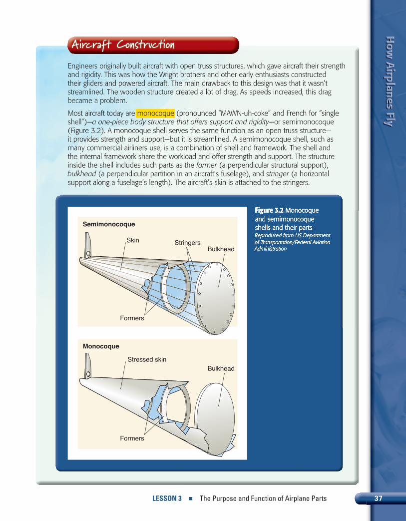
Engineers originally built aircraft with open truss structures, which gave aircraft their strength and rigidity. This was how the Wright brothers and other early enthusiasts constructed their gliders and powered aircraft. The main drawback to this design was that it wasn’t streamlined. The wooden structure created a lot of drag. As speeds increased, this drag became a problem.
Most aircraft today are monocoque (pronounced “MAWN-uh-coke” and French for “single shell”)—a one-piece body structure that offers support and rigidity—or semimonocoque (Figure 3.2). A monocoque shell serves the same function as an open truss structure—it provides strength and support—but it is streamlined. A semimonocoque shell, such as many commercial airliners use, is a combination of shell and framework. The shell and the internal framework share the workload and offer strength and support. The structure inside the shell includes such parts as the former (a perpendicular structural support), bulkhead (a perpendicular partition in an aircraft’s fuselage), and stringer (a horizontal support along a fuselage’s length). The aircraft’s skin is attached to the stringers.
Aircraft Construction
Figure 3.2 Figure 3.2 Figure 3.2 Monocoque Monocoque Monocoque and semimonocoque and semimonocoque and semimonocoque shells and their partsshells and their partsshells and their partsReproduced from US Department Reproduced from US Department Reproduced from US Department of Transportation/Federal Aviation of Transportation/Federal Aviation of Transportation/Federal Aviation AdministrationAdministrationAdministration
FlightJones & Bartlett PublishersMorales Studio30652_CH00_LS03__FIG02 04-28-11
BulkheadStringersSkin
Semimonocoque
Monocoque
BulkheadStressed skin
Formers
Formers
38 CHAPTER 1 How Airplanes Fly
In the previous lesson you read about the force called weight. The fuselage and the payload carried in the body make up the bulk of an aircraft’s weight. The center of gravity is inside the fuselage. During fl ight the aircraft rotates around the center of gravity because of torque generated by a number of different aircraft parts. Torque is a twisting or rotating force. The fuselage must be strong enough to withstand torque.
Wing Shapes
Wings are one of the main aircraft parts attached to the fuselage. Like the airplane body, wings come in all different shapes and sizes, depending on the plane’s purpose and how much lift it requires.
Wing Positions and PartsManufacturers generally place wings in three locations on the fuselage: at the top, toward the middle, and at the lower portion of the body. Engineers refer to these designs as high-, mid-, and low-wing. The position of the wings depends on
Figure 3.3 Figure 3.3 Figure 3.3 Wing partsWing partsWing partsReproduced from US Department of Transportation/Federal Aviation AdministrationReproduced from US Department of Transportation/Federal Aviation AdministrationReproduced from US Department of Transportation/Federal Aviation Administration
FlightJones & Bartlett PublishersMorales Studio30652_CH01_LS03__FIG03 04-28-11
Fuel tank
Skin
Wing flap
Spar
Wingtip
Ribs
Stringers

LESSON 3 ■ The Purpose and Function of Airplane Parts 39
How
Airplanes Fly
How
Airplanes Fly
How
Airplanes Fly
the aircraft’s mission. A monoplane is a plane with a single set of wings, while a biplane is an aircraft with two sets of wings. Monoplane wings can be low, mid, or high. A biplane will have some combination, although most have one high and one low set of wings.
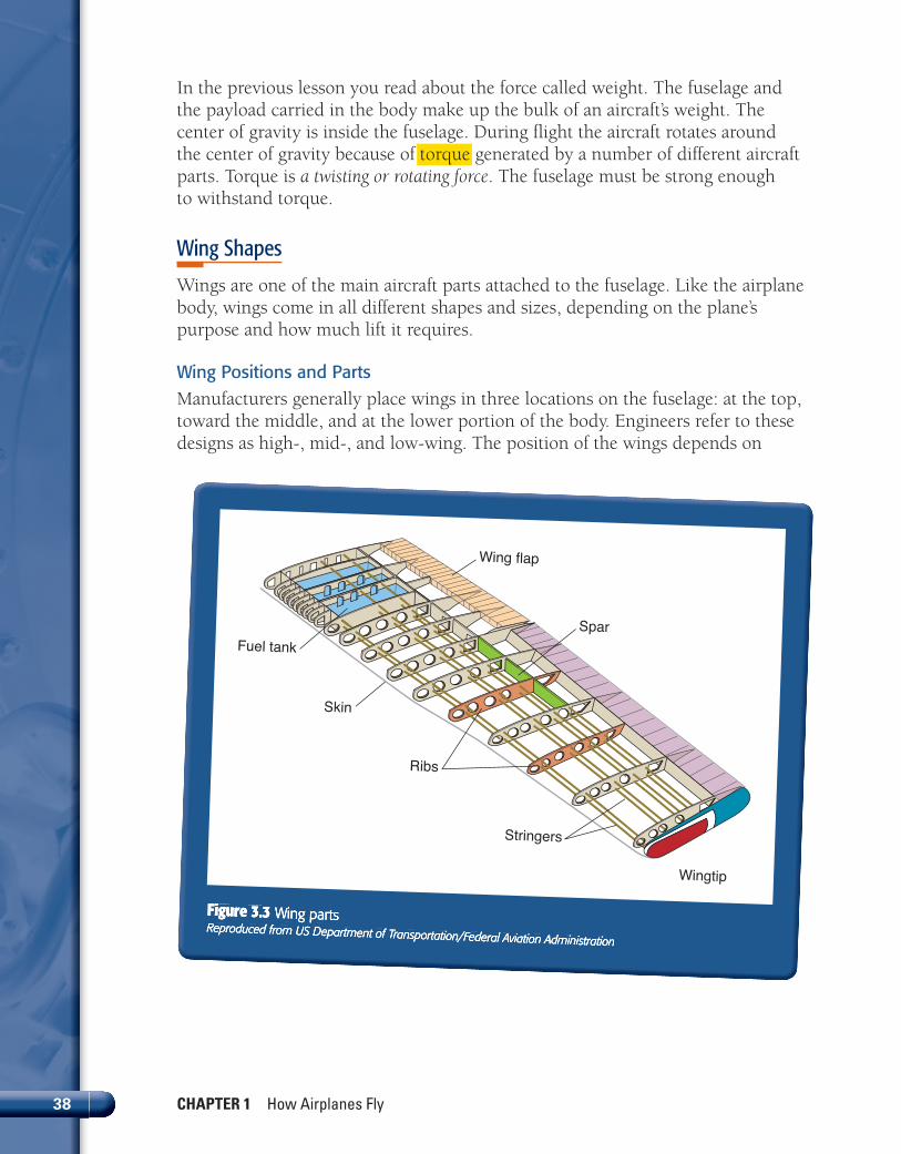
A wing’s main internal parts are spars, ribs, and stringers. Spars and stringers run lengthwise. And ribs run a wing’s width and determine how thick it will be. Fuel tanks are usually also a part of the wing. They either are mounted inside the wing in containers or are part of the wing’s structure (Figure 3.3).
Wing SizeA wing’s aspect ratio—a measure of how long and wide a wing is from tip to tip—depends on the plane’s function. For example, a glider, which travels at slow speeds, has high-aspect-ratio wings with long wingspans. By contrast, a fi ghter like the F-16, which fl ies at high speeds with a powerful engine, has low-aspect-ratio wings and short wingspans.
Long, thin wings, such as a glider has, experience low induced drag. Wings designed in an elliptical shape have less drag than rectangular wings. The amount of an aircraft’s induced drag is inversely proportional to its aspect ratio. That is, the greater the aspect ratio, the lower the induced drag. And the lower the aspect ratio, the higher the induced drag. Further, the lower the induced drag, the greater the lift, and vice versa.
Because gliders fl y with no engine, their fl ight is relatively slow and their fl ight path is a constant decrease in altitude. This slow, steady descent gives them a small glide angle, where the fl ight path intersects with the ground at an angle (Figure 3.4).
Figure 3.4 Figure 3.4 Figure 3.4 The glide angleThe glide angleThe glide angleModifi ed from NASA/Glenn Modifi ed from NASA/Glenn Modifi ed from NASA/Glenn Research CenterResearch CenterResearch Center
FlightJones & Bartlett PublishersMorales Studio30652_CH01_LS03__FIG04 05-09-11
Horizontal distance
Horizontal
Vertical heightFlight path
a
a = Glide angle a
Wing TIPS—depends on the plane’s Wing

40 CHAPTER 1 How Airplanes Fly
An aircraft’s glide angle is a measure of its fl ying effi ciency. A glider’s high-aspect-ratio wings give it this effi ciency because with the greater wing area, the wings generate plenty of lift. The wings’ elliptical shape reduces drag and results in a long, slow fl ight.
The space shuttle with its low-aspect-ratio wings and thick chords from leading to trailing edge was a different case. This aircraft had to perform two very different duties. It used rocket engines to lift off, but it glided powerlessly back to Earth. On its return, the shuttle had a large glide angle because of its low-aspect-ratio wing shape and high speeds. This low aspect ratio and large glide angle meant it was a very poor glider.
Wing AnglesMany planes have wings whose tips are higher than their roots—the part that attaches to the plane. The angle that a wing makes with the aircraft’s horizontal is the dihedral angle (Figure 3.5). This angle gives an aircraft roll stability and helps it return to level fl ight.
Large commercial airliner wings have dihedral angles. Fighters, on the other hand, need to maneuver more, so they don’t have dihedral. In fact, to increase fi ghters’ ability to roll, engineers design many with a negative dihedral called anhedral (Figure 3.5). Aircraft with anhedral have wingtips closer to the ground than their wing roots. The Wright brothers’ 1903 fl yer had a slight anhedral.
Figure 3.5 Figure 3.5 Figure 3.5 Front view of wingsFront view of wingsFront view of wings
Modifi ed from NASA/Glenn Research CenterModifi ed from NASA/Glenn Research CenterModifi ed from NASA/Glenn Research Center
FlightJones & Bartlett PublishersMorales Studio30652_CH01_LS03__FIG05 05-09-11
Wingtip WingtipWing
Front view
Front view
Dihedral angle
Anhedral angle

LESSON 3 ■ The Purpose and Function of Airplane Parts 41
How
Airplanes Fly
How
Airplanes Fly
How
Airplanes Fly
The Types, Purpose, and Function of Airfoil DesignWing shape actually involves more than aspect ratios and angles. The relationship of an airfoil’s upper and lower surfaces also plays a big role in generating lift.
Airfoil Camber
In the opening lesson you read about the curve in an airfoil called the camber. The mean camber line is a reference line from leading to trailing edge drawn an equal distance from the upper and lower wing surfaces. In a symmetrical airfoil—an airfoil in which the upper surface and the lower surface have the same shape—
A 1970s NASA invention called the winglet graces many modern wings. A winglet is a plate attached to a wingtip or a wingtip bent upward. The winglet increases effi ciency by decreasing drag.
In the previous lesson you read about wingtip vortices that twirl the air into a whirlpool and create induced drag. Winglets reduce the strength of these tip vortices so the air fl ows more easily across the wing (Figure 3.6). This smoother airfl ow has other consequences: tests at NASA on a Boeing 707 with winglets showed a 6.5 percent decrease in fuel consumption.
Winglets
Figure 3.6 Figure 3.6 Figure 3.6 WingletsWingletsWingletsModifi ed from NASA/Glenn Research CenterModifi ed from NASA/Glenn Research CenterModifi ed from NASA/Glenn Research Center
FlightJones & Bartlett PublishersMorales Studio30652_CH01_LS03__FIG06 05-09-11
Weakervortex
Weakervortex
Without winglets With winglets
Vortex
Vortex
Winglets reduce induced drag component

42 CHAPTER 1 How Airplanes Fly
the mean camber line and chord line will be the same. But in most airfoils the upper surface curves more than the lower surface, so the mean camber line will lie above the chord line (Figure 3.7).
You can also measure an airfoil’s thickness. The thickness is the maximum distance between the upper and lower
wing surfaces. To determine thickness you would measure the thickest vertical line of the wing, toward the rounded leading edge.
Types, Purpose, and Function
Airfoils come in many combinations of camber and thickness because no one design meets every aircraft’s needs. The aircraft’s weight, speed, and purpose determine the wing’s shape (Figure 3.8).
No one airfoil has been found that satisfi es every fl ight requirement.
Engineers have found that concave lower surfaces—hollow and rounded like an ice cream scoop—produce the greatest lift at low speeds. However, this “scooped out” lower surface doesn’t work well at high speeds.
Streamlined airfoils result in other tradeoffs. They may work at high speeds because they produce little wind resistance, but they don’t create enough lift. So, modern aircraft have airfoils that fi nd a happy medium between the two.
If you tried fl ying with a wing in the shape of a teardrop, you’d have a very streamlined airfoil, but it wouldn’t create any difference in pressure between top and bottom and would have no lift at a zero angle of attack. The airfl ow over the top and bottom would be the same. If you chopped this teardrop in half lengthwise (along the chord line) so it was more in the shape of a typical airfoil (Figure 3.9), the top would be far more curved than the bottom. This would create the right conditions for lift.
Figure 3.7 Figure 3.7 Figure 3.7 Airfoil partsAirfoil partsAirfoil partsReproduced from US Department of Transportation/Federal Aviation AdministrationReproduced from US Department of Transportation/Federal Aviation AdministrationReproduced from US Department of Transportation/Federal Aviation Administration
FlightJones & Bartlett PublishersMorales Studio30652_CH01_LS03__FIG07 05-09-11
Chord line
Mean camber line
Leading edge
Trailing edge
Camber of upper surface
Camber of lower surface
Wing TIPSWing

LESSON 3 ■ The Purpose and Function of Airplane Parts 43
How
Airplanes Fly
How
Airplanes Fly
How
Airplanes Fly
Figure 3.8 Figure 3.8 Figure 3.8 Airfoil designsAirfoil designsAirfoil designsReproduced from US Department Reproduced from US Department Reproduced from US Department of Transportation/Federal Aviation of Transportation/Federal Aviation of Transportation/Federal Aviation Administration Administration Administration
FlightJones & Bartlett PublishersMorales Studio30652_CH01_LS03__FIG08 04-28-11
Early airfoil
Later airfoil
Clark “Y” airfoil (subsonic)
Laminar flow airfoil (subsonic)
Circular arc airfoil (supersonic)
Double wedge airfoil (supersonic)
Figure 3.9 Figure 3.9 Figure 3.9 (a) A teardrop-(a) A teardrop-(a) A teardrop-shaped airfoil; (b) the shaped airfoil; (b) the shaped airfoil; (b) the same airfoil cut in half same airfoil cut in half same airfoil cut in half lengthwiselengthwiselengthwise
FlightJones & Bartlett PublishersMorales Studio30652_CH01_LS03__FIG09 04-27-11
Lift
Chord line
Airflow Fast moving air
Fast moving air
Airflow Fast moving air
Slow moving air
(a)
(b)

44 CHAPTER 1 How Airplanes Fly
When airfoil curvature fi nds the right balance, the airstream striking the lower and fl atter wing surface fl ows down to create an opposite upward lift. And the stream hitting the upper and more curved wing surface bends up.
Furthermore the pressure difference that a properly designed airfoil generates between its upper and lower surfaces is not enough to produce all of the lift force required (although it contributes greatly to it). With the right camber, the low pressure above the wing fl ows down to create downwash. Downwash is a downward fl ow of air. Meanwhile, the high-pressure air is fl owing under the wing toward the trailing edge. When these two pressure areas meet, Newton’s third law of action and reaction comes into play. The reaction of the downward backward fl ow of air results in an upward forward force on the airfoil.
The Role of Stabilizers and RuddersAnother crucial aircraft part is the tail section. Pilots control their aircraft with the help of stabilizers and rudders. These two parts are attached to the rear of the fuselage at the tail (Figure 3.10). The vertical and horizontal stabilizers don’t move; they are fi xed in place. The rudder does move.
Stabilizers do just what it sounds like—they keep an aircraft stable so it can maintain a straight fl ight path. The vertical stabilizer prevents the nose from roving side to side. The horizontal stabilizers keep it from bobbing up and down.
Figure 3.10 Figure 3.10 Figure 3.10 Stabilizers Stabilizers Stabilizers and ruddersand ruddersand ruddersReproduced from US Reproduced from US Reproduced from US Department of Transportation/Department of Transportation/Department of Transportation/Federal Aviation AdministrationFederal Aviation AdministrationFederal Aviation Administration
FlightJones & Bartlett PublishersMorales Studio30652_CH01_LS03__FIG10 05-09-11
Horizontal stabilizer
Vertical stabilizer
Rudder
Trim tabs
Elevator
Wing TIPSWing

LESSON 3 ■ The Purpose and Function of Airplane Parts 45
How
Airplanes Fly
How
Airplanes Fly
How
Airplanes Fly
The rudder, fastened with hinges to the back of the vertical stabilizer, lets the pilot steer the aircraft by moving the tail left and right. Another airplane part, called an elevator—attached with hinges to the back of the horizontal stabilizer—can direct the tail either up or down at the pilot’s discretion. These movable parts at a stabilizer’s rear change the force the stabilizers produce. Both the rudder and the elevator have trim tabs, also attached by hinges. Trim tabs are even smaller than the rudder and elevator and fi ne-tune the left-right, up-down movements by reducing pressure. They help “trim,” or balance, the fl ight.
The Positions of Flaps, Spoilers, and Slats on an AircraftAn airplane’s main fi xed wings also have moving parts. These are fl aps, spoilers, and slats (Figure 3.11). They play a major role during takeoff and landing when aircraft velocity is relatively slow.
A fl ap is a hinged device at a wing’s trailing edge that produces lift. It moves in two directions: it bends downward and stretches aft (toward the tail). Flaps on large aircraft such as commercial airliners are more complex than those on smaller planes.
A spoiler is a small, fl at plate that attaches to the tops of the wings with hinges; it increases drag.
At the front of the wings on some aircraft are slats. A slat is also a movable, hinged part that pivots down to generate more force. The next lesson will discuss the effects of fl aps, spoilers, and slats on fl ight and motion.
How the Airfl ow and Airfoil Affect Flight MovementThe term fl ow turning describes much of what you’ve read so far in this lesson, most particularly airfoil design and wing controls such as fl aps. The amount of lift an airfoil generates depends on how much it is able to change the path the airstream takes. How much an object can turn fl ow depends on its shape.
Figure 3.11 Figure 3.11 Figure 3.11 Flaps, spoilers, and slatsFlaps, spoilers, and slatsFlaps, spoilers, and slats
Modifi ed from NASA/Glenn Research CenterModifi ed from NASA/Glenn Research CenterModifi ed from NASA/Glenn Research Center
FlightJones & Bartlett PublishersMorales Studio30652_CH01_LS03__FIG11 04-18-11
Flaps
SpoilerSlats

46 CHAPTER 1 How Airplanes Fly
If air fl ows evenly along both sides of a wing—as in that previous case of the symmetrical teardrop-shaped airfoil—the wing produces no lift at zero angle of attack. But if the airfoil curves dramatically toward its trailing edge, the fl ow is turned and the wing produces a large amount of lift. In short the greater the fl ow turning, the greater the lift. In Figure 3.12 the airfoils have identical leading edges. It is their trailing edges that determine whether an airfoil can turn fl ow and cause lift.
Control surfaces such as fl aps, spoilers, and slats let pilots manipulate fl ow turning. With hinged devices down, the wing takes on a more sharply curved shape at its trailing edge to generate more lift. Extending fl aps aft and slats forward also expands a wing’s aspect ratio, which also helps lift. If the pilot desires less lift, he or she maneuvers the aft section up or activates the spoilers.
The Purpose and Function of Propellers, Turbines, Ramjets, and Rocket Propulsion SystemsPropulsion systems provide the aircraft’s thrust to maintain forward movement. The word propulsion has two Latin roots: pro for forward and pellere for to drive. Therefore, propulsion means to drive forward or to push forward.
Figure 3.12 Figure 3.12 Figure 3.12 TopTopTop: An airfoil : An airfoil : An airfoil producing little fl ow turning; producing little fl ow turning; producing little fl ow turning; BottomBottomBottom: an airfoil producing : an airfoil producing : an airfoil producing a lot of fl ow turninga lot of fl ow turninga lot of fl ow turningReproduced from NASA/Glenn Reproduced from NASA/Glenn Reproduced from NASA/Glenn Research CenterResearch CenterResearch Center
FlightJones & Bartlett PublishersMorales Studio30652_CH01_LS03__FIG12 04-27-11
FlightJones & Bartlett PublishersMorales Studio30652_CH01_LS03__FIG12 04-27-11

LESSON 3 ■ The Purpose and Function of Airplane Parts 47
How
Airplanes Fly
How
Airplanes Fly
How
Airplanes Fly
A propulsion system is an engine that generates thrust to move an aircraft forward. These systems illustrate Newton’s third law of action and reaction. Engines accelerate air—a gas—in one direction, and this action propels the aircraft in the opposite direction, which is the reaction. The engine pushes on the gas, and the gas pushes back. Propulsion systems are the machines that accelerate the gas. Propellers do this mechanically; jets do it both mechanically and through a chemical reaction.
The amount of thrust an engine generates depends on how much gas it pushes through the propulsion system and the velocity at which the gas exits the system. The four main propulsion systems are propellers, turbines, ramjets/scramjets, and rockets. Each produces thrust in different ways.
Propulsion systems serve two roles. When an aircraft is in straight and level fl ight, the thrust an engine produces must balance the drag. When an aircraft is accelerating, the thrust produced must exceed the drag. The greater the difference between thrust and drag—called excess thrust—the faster the plane accelerates.
When choosing which type of propulsion system an aircraft will use, engineers consider what’s more important for that particular plane: excess thrust, or high engine effi ciency and low fuel usage. For an airliner, which generally travels at a steady, cruising speed over long distances, fuel effi ciency takes top priority. But for a fi ghter, it’s acceleration.
A C-130H3 taxies down the runway during a fl ight test at Edwards Air Force
A C-130H3 taxies down the runway during a fl ight test at Edwards Air Force
A C-130H3 taxies down the runway during a fl ight test at Edwards Air Force Base, California. It boasts eight-bladed NP-2000 propellers made for Base, California. It boasts eight-bladed NP-2000 propellers made for Base, California. It boasts eight-bladed NP-2000 propellers made for generating more thrust with greater effi ciency.generating more thrust with greater effi ciency.generating more thrust with greater effi ciency.Courtesy of USAF/John PerryCourtesy of USAF/John PerryCourtesy of USAF/John Perry
Wing TIPSan engine that generates thrust Wing

48 CHAPTER 1 How Airplanes Fly
Propellers
Many airliners and cargo planes use turboprops and high bypass turbofans because propellers and turbofans offer effi ciency and low fuel usage.
Propellers have anywhere from two to eight blades attached to a hub. An engine provides the power to turn the blades. Propeller blades not only are long and thin like wings, but they also act like wings. They have camber, chord lines, and leading and trailing edges. They are subject to all the same forces that an airfoil is, including drag and lift. They generate thrust by accelerating the air that passes through them. Airfoil shape, the blades’ angle of attack, and the engine’s power all determine the amount of thrust produced.
Because a propeller is a rotating airfoil, it also generates lift as the blades move through the air. Propeller blades experience low- and high-pressure areas when producing lift. The low-pressure area forms behind the blades, and the high-pressure area sits in front of them, creating a lifting surface. This difference in pressure draws air through the propellers and pulls the plane forward.
As the blades spin, the tips have a faster linear speed than the hub because the tips have farther to travel in the same amount of time. To deal with this difference in speed along a blade and to produce uniform lift, blades are twisted from hub to tip. This twist introduces an angle of attack, and the angle of attack is lower at the tip than it is at the hub to accommodate the different speeds along the blade. That is, the blades are less twisted at the tip and more twisted at the hub. If the angle of attack were the same all along the blade, the hub would spin at a negative angle of attack and the tip would stall.
Airmen work on a C-130E Airmen work on a C-130E Airmen work on a C-130E
propeller at their air base propeller at their air base propeller at their air base
in Southwest Asia. in Southwest Asia. in Southwest Asia. Courtesy of USAF/SrA Laura TurnerCourtesy of USAF/SrA Laura TurnerCourtesy of USAF/SrA Laura Turner

LESSON 3 ■ The Purpose and Function of Airplane Parts 49
How
Airplanes Fly
How
Airplanes Fly
How
Airplanes Fly
Turbines
Turbine (jet) engines can fl y at higher speeds than propellers, although they also work at low cruising speeds. Aircraft manufacturers use gas turbines for everything from commercial airliners to military cargo planes to fi ghters engaged in air-to-air combat. One type of turbine engine is the turboprop, which boasts a turbine engine that turns a propeller.
These versatile engines—turboprop, turbojet, turbofan, and turboshaft—produce thrust by pushing gas out their exhaust at great velocity.
Frank Walker Caldwell (1889–1974) was with the US Army Air Service’s Propeller Department of the Airplane Engineering Division at McCook Field in Dayton, Ohio, during World War I. Just a few years before, he had graduated from the Massachusetts Institute of Technology with a degree in mechanical engineering. It was up to him, as the Army Air Service’s chief engineer, to design and test the best possible propellers for the Army and the Navy.
Just as World War II spurred advances in jet engines, World War I pushed advances in propellers. While the Wright brothers get credit for fi rst discovering that propellers act like rotating wings, Caldwell made some very important observations and inventions as well.
The newer, more powerful aircraft rolling off the assembly lines beginning in World War I called for stronger, more-effi cient propellers. Planes had fi xed-pitch, wood propellers. The blade angle was always the same. But an effi cient angle for a blade when an airplane is cruising isn’t effi cient at takeoff. What grew out of Caldwell’s time as chief engineer were variable-pitch propellers that could be removed from the hub and their pitch changed with the plane on the ground and the engine off. These were ground-adjustable pitch propellers. They were also metal rather than wood.
In 1929, Caldwell left the military and joined the Hamilton Standard Propeller Corporation where he came up with a controllable-pitch propeller that could be adjusted during fl ight. This propeller had two positions, one good for takeoff, the other good for cruising. Later while still at Hamilton, Caldwell contributed to the Hydromatic constant-speed propeller, which automatically changed blade angle when the pilot changed engine speed. This propeller played a huge role in Allied aircraft during World War II.
Designing a Better Propeller
A USAF C27J Spartan, a twin turboprop aircraftA USAF C27J Spartan, a twin turboprop aircraftA USAF C27J Spartan, a twin turboprop aircraftCourtesy of USAFCourtesy of USAFCourtesy of USAF

50 CHAPTER 1 How Airplanes Fly
Developed during World War II by Germany and Britain, gas turbines create hot exhaust gas and pass it through a nozzle to thrust an aircraft forward. Gas turbines depend on oxygen from the surrounding air for combustion, the process of burning. Many aircraft today use gas turbines. Airlines equip their passenger airliners with turbines because they often travel great distances at high speeds. Fighters need them because they must accelerate quickly in combat. And although cargo planes might not call for speed, they do carry heavy loads long distances.
Ramjets
Ramjets are lighter and simpler than turbojets. Like a gas turbine, they combust fuel and derive thrust from the hot exhaust accelerated through the nozzle. The combustion pressure must be higher than the pressure at the nozzle for the engine to work. The working fl uid is external air brought into the system—as with a gas turbine’s operations. The system exerts a force on the external air to accelerate it, and the reaction produced is the thrust force on the system. Ramjets, like jet engines, rely more on gas exit velocity than on mass fl ow of gas through the engine.
An F-16 Fighting Falcon has a typical jet engine. This F-16 is fl ying over
An F-16 Fighting Falcon has a typical jet engine. This F-16 is fl ying over
An F-16 Fighting Falcon has a typical jet engine. This F-16 is fl ying over
Nevada in early 2011 on a training exercise.Nevada in early 2011 on a training exercise.Nevada in early 2011 on a training exercise.
Courtesy of USAF/SSgt Benjamin WilsonCourtesy of USAF/SSgt Benjamin WilsonCourtesy of USAF/SSgt Benjamin Wilson

LESSON 3 ■ The Purpose and Function of Airplane Parts 51
How
Airplanes Fly
How
Airplanes Fly
How
Airplanes Fly
Ramjets can’t provide thrust unless an aircraft is already moving. Therefore, ramjets must operate with other propulsion systems, such as rocket engines, that provide an initial thrust. These engines are used for supersonic fl ight. But they can’t combust fuel when traveling above the speed of sound unless the inlet slows the air to below the speed of sound. So aircraft with ramjets are capable of fl ying above the speed of sound, but the air must be slowed entering the engine for the ramjet to burn the fuel and create thrust. Aircraft designers use ramjets despite these complications because they are more effi cient than other jet engines at these speeds. More-modern scramjets are an improvement over ramjets because the fl ow of air does not have to be reduced to less than the speed of sound. A scramjet allows supersonic combustion, improving the effi ciency of the engine at high supersonic speeds.
Rocket Engines
The working fl uid for propellers, turbines, and ramjets is the surrounding air. A rocket engine’s working fl uid is hot rocket exhaust. This is because rockets carry their own oxygen to mix with fuel. This allows them to travel in space, where there is no oxygen. The other three engine types can’t fl y into space because they don’t carry their own oxygen but instead draw on external air.
While rockets work for space travel, they can also fl y in Earth’s atmosphere. For instance, they work with ramjets for in-atmosphere fl ight. Engineers used them in the fi rst aircraft to break the sound barrier, such as the Bell X-1 in 1947.
An X-15 fl ies over the desert in the 1960s. This aircraft fl ew with a rocket engine. An X-15 fl ies over the desert in the 1960s. This aircraft fl ew with a rocket engine. An X-15 fl ies over the desert in the 1960s. This aircraft fl ew with a rocket engine. Courtesy of NASA/USAFCourtesy of NASA/USAFCourtesy of NASA/USAF
52 CHAPTER 1 How Airplanes Fly
The two main types of rockets are liquid rockets and solid rockets. The fi rst uses liquid propellant—a mix of fuel and oxidizer (an oxidizer is a substance that includes oxygen to aid combustion). A liquid rocket stores its liquids separately, then mixes them in a combustion chamber in the nozzle. The liquid is injected into the combustion chamber and ignited. The resulting hot gas ejects out the nozzle. A solid propellant is one where the ingredients are already mixed but they don’t burn until ignited. The advantage of the liquid propellant is that the combustion can be turned on and off by no longer pumping the liquids into the combustion chamber. But a solid propellant, once lit, burns through unless you destroy its casing.
In general liquid rockets are heavier than solid rockets and more complex because of the pumps and storage tanks. Also you often can’t load the combustible liquids into the tanks until right before launch. A solid propellant rocket, on the other hand, can sit in storage for a long time.
This lesson introduced you to airplane parts and their functions. In the next lesson, you’ll read about aircraft motion and how to control it. After that, you’ll study how aircraft engines work and the latest innovations in aircraft technology.

LESSON 3 ■ The Purpose and Function of Airplane Parts 53
How
Airplanes Fly
How
Airplanes Fly
How
Airplanes Fly
POINTSCHECK✔ POINTSPOINTSPOINTSCHECKCHECKCHECKCHECKCHECKCHECK✔CHECKCHECKCHECKCHECK✔✔CHECK✔CHECK✔CHECK✔CHECK✔✔CHECKCHECKCHECKCHECK✔✔✔✔✔✔✔CHECK✔CHECK✔CHECK✔CHECK✔✔Lesson 3 ReviewUsing complete sentences, answer the following questions on a sheet of paper.
1. A fuselage must be strong enough to withstand which force?
2. Why must a glider have high-aspect-ratio wings with long wingspans?
3. Where does the mean camber line usually lie in relation to the chord line?
4. At which speeds do wings with a concave-shaped lower surface produce the greatest lift?
5. What do a vertical stabilizer and a horizontal stabilizer do?
6. What does an elevator do?
7. When do fl aps, spoilers, and slats play a major role?
8. Does a slat pivot up or down? Why?
9. How much an object can turn fl ow depends on what?
10. Which parts of a wing let a pilot manipulate fl ow turning?
11. How do turbine engines produce thrust?
12. What must already be happening for a ramjet to provide thrust?
APPLYING YOUR LEARNINGAPPLYING YOUR LEARNINGAPPLYING YOUR LEARNINGAPPLYING YOUR LEARNINGAPPLYING YOUR LEARNINGAPPLYING YOUR LEARNINGAPPLYING YOUR LEARNINGAPPLYING YOUR LEARNING
13. Why is the air pressure both under and over a symmetrical airfoil the same?