Embed Size (px)
Citation preview

SHANIL BATOHI
Lesson 4:
Active Electronic
Components
Diode, Light Emitting
Diode, Transistor
SHANIL BATOHI
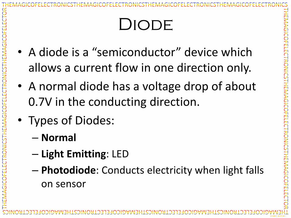
Diode
• A diode is a “semiconductor” device which allows a current flow in one direction only.
• A normal diode has a voltage drop of about 0.7V in the conducting direction.
• Types of Diodes:
– Normal
– Light Emitting: LED
– Photodiode: Conducts electricity when light falls on sensor

SHANIL BATOHI
Symbols and Images
Diode
LED (Light Emitting Diode)
Photodiode (and matching Infrared LED)

SHANIL BATOHI
The Transistor
• Greatest invention of the 20th century
• The basis for all electronics and the entire information age.
• A transistor is a device that can behave as a switch or amplify an electrical current.
• There are two polarities (NPN and PNP) – current flows in opposite directions.
B (Base)
C (Collector)
E (Emitter)
NPN Transistor PNP Transistor
B (Base)
C (Collector)
E (Emitter)

SHANIL BATOHI
Transistor Operation #1
• Digital circuits (computers etc.) use transistors as switches. In this configuration the transistors has two possible states (0 or 1) and is hence a binary circuit.
• Analogue circuits (radio, hearing aid) use transistors as amplifiers.
• A transistor has 3 legs called the Base (B), Emitter and Collector.

SHANIL BATOHI
Transistor Operation #2
• When a small electrical voltage is applied to the Base (B) a much larger current is able to flow from C (collector) to E (emitter). Like a diode current can only flow in one direction.
• The amount of current that flows from C to E depends on gain. With a gain of 100, if 1mA flows into the base, 100mA can flow from collector to emitter.
• Base/Emitter voltage is maximum of 0.7V (when on).
10mA
10mA x 100 = 1A B
C
E

SHANIL BATOHI
Simple Transistor Circuit
1. Resistor R1 ensures that the voltage at the base of the transistor is normally 0V. The transistor is thereof of and no current flows through the LED. The LED is off.
2. When the salt water (which is conductive) reaches the level of the sensors, a current flows from the battery into resistor R2 and into the base of the transistor.
3. The transistor switches on and current flows from the Collector to the Emitter. Current therefore flows through the LED and it switches on.
4. Resistor R3 makes sure that too much current does not flow. This could damage the transistor or the LED.
Salt water
9V battery
LED
Transistor
Resistor
Resistor
Resistor
B
C
ER1
R2
R3
1
4
3
2

SHANIL BATOHI
possible Transistor circuits
• Touch control
• In-wall Power line detector
• Amplifier (more complex)
• LED flasher
• Light sensor
• Sound detector
SHANIL BATOHI
The End
Next Lesson: Circuit Building