Embed Size (px)
Citation preview
Lesson 5
Basic Laws of Electric Circuits
Equivalent Resistance
Basic Laws of CircuitsEquivalent Resistance:
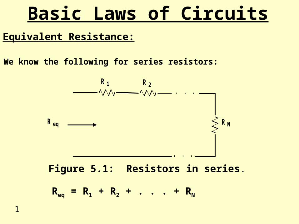
We know the following for series resistors:
. . .
. . .R 1 R 2
R eq R N
Figure 5.1: Resistors in series.
Req = R1 + R2 + . . . + RN
1
Basic Laws of CircuitsEquivalent Resistance:
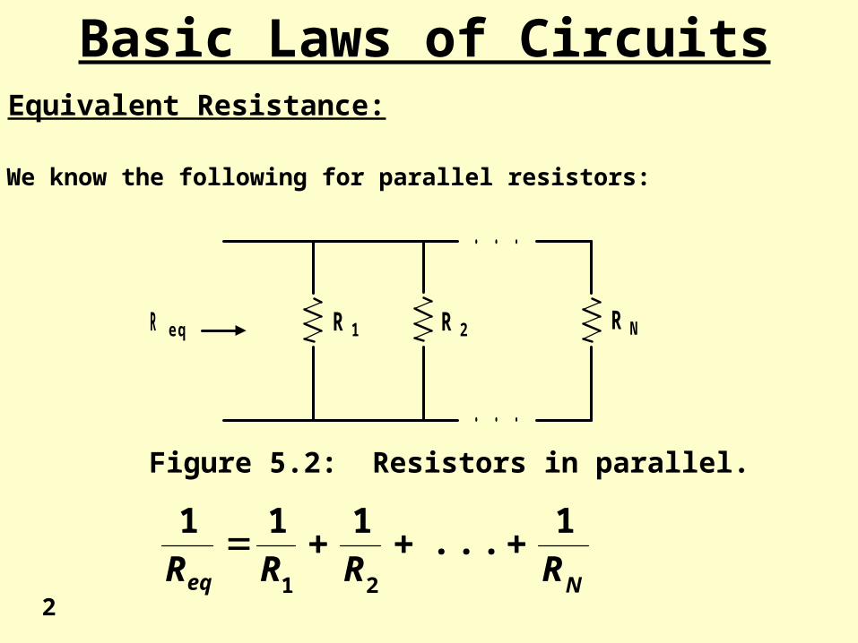
We know the following for parallel resistors:
. . .
. . .
R e q R 1 R 2 R N
Figure 5.2: Resistors in parallel.
Neq RRRR
1...
111
21
2
Basic Laws of CircuitsEquivalent Resistance:
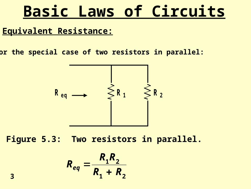
For the special case of two resistors in parallel:
R e q R 1 R 2
Figure 5.3: Two resistors in parallel.
21
21
RR
RRReq
3
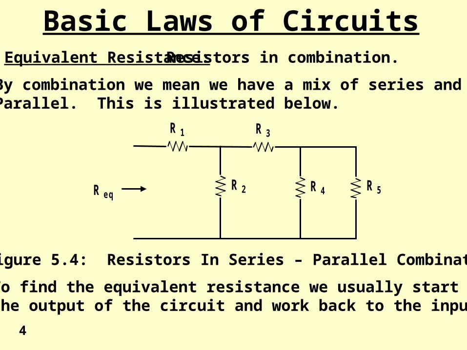
Basic Laws of CircuitsEquivalent Resistance: Resistors in combination.
By combination we mean we have a mix of series and Parallel. This is illustrated below.
R 1
R 2
R 3
R 4 R 5R e q
Figure 5.4: Resistors In Series – Parallel Combination
To find the equivalent resistance we usually start atthe output of the circuit and work back to the input.
4
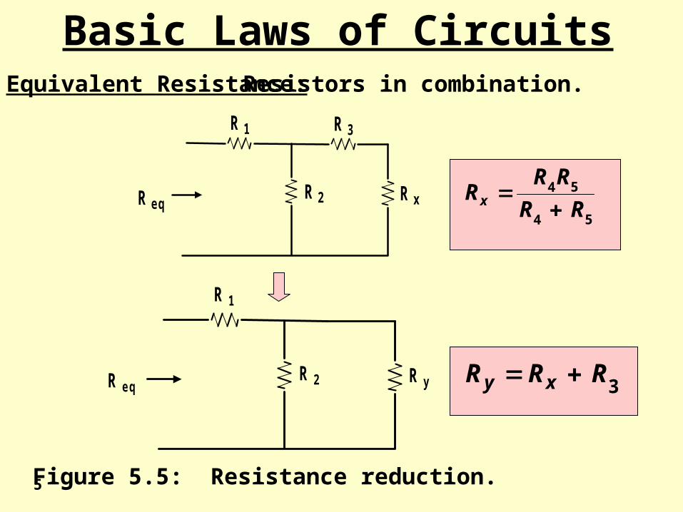
Basic Laws of CircuitsEquivalent Resistance: Resistors in combination.
R 1
R 2
R 3
R xR e q54
54
RR
RRRx
R 1
R 2 R yR e q 3RRR xy
Figure 5.5: Resistance reduction.5
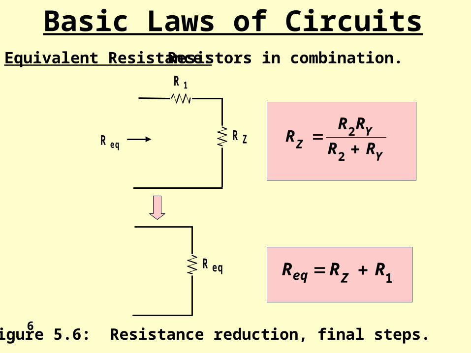
Basic Laws of CircuitsEquivalent Resistance: Resistors in combination.
R 1
R ZR e qY
YZ RR
RRR
2
2
R e q1RRR Zeq
Figure 5.6: Resistance reduction, final steps.6
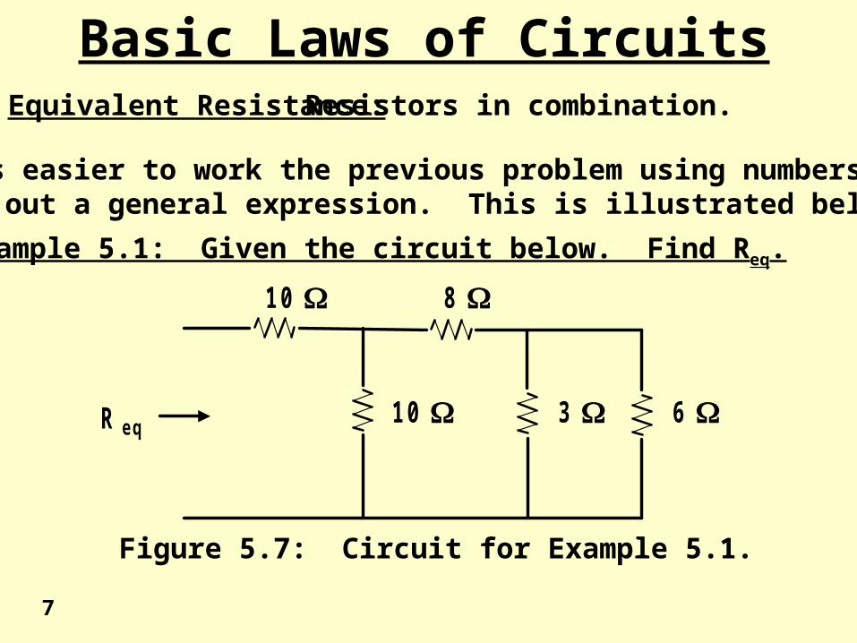
Basic Laws of CircuitsEquivalent Resistance: Resistors in combination.
It is easier to work the previous problem using numbers than towork out a general expression. This is illustrated below.
Example 5.1: Given the circuit below. Find Req.
R e q6 3
8
1 0
1 0
Figure 5.7: Circuit for Example 5.1.
7
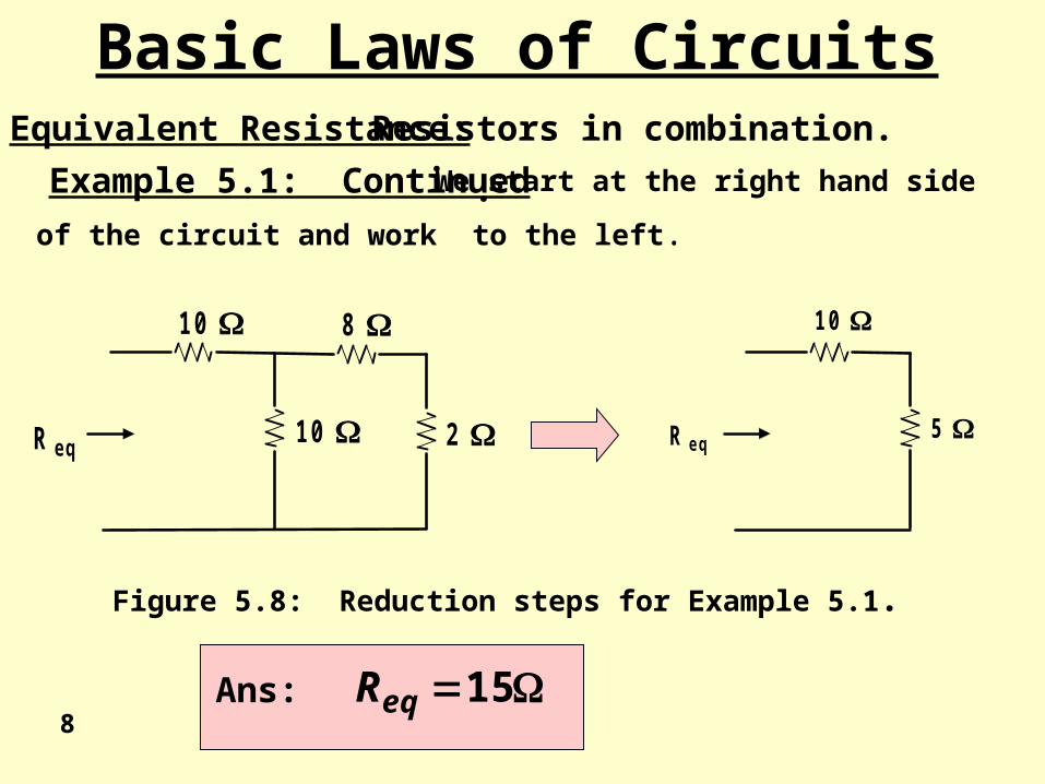
Basic Laws of CircuitsEquivalent Resistance: Resistors in combination.
Example 5.1: Continued . We start at the right hand side
of the circuit and work to the left.
1 0
1 0
8
2 R e q
1 0
5 R e q
Figure 5.8: Reduction steps for Example 5.1.
15eqRAns: 8
Basic Laws of CircuitsEquivalent Resistance: Resistors in combination.
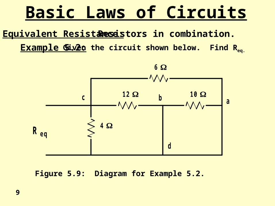
Example 5.2: Given the circuit shown below. Find Req.
c b a
d
R e q4
1 2
6
1 0
Figure 5.9: Diagram for Example 5.2.
9
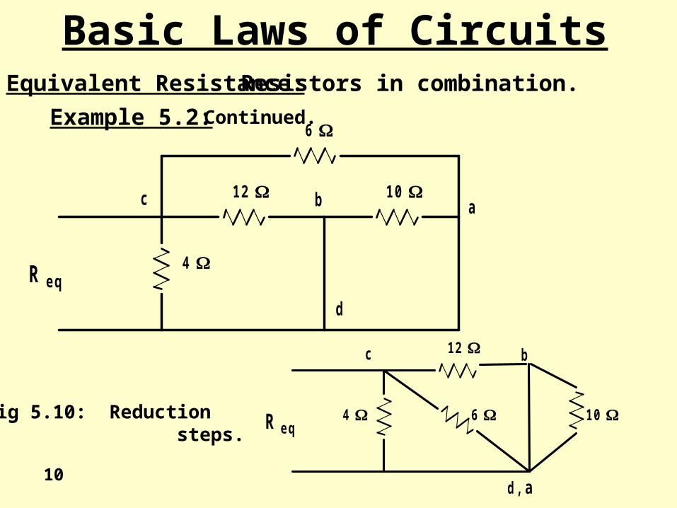
Basic Laws of CircuitsEquivalent Resistance: Resistors in combination.
Example 5.2: Continued.
c b
d , a
R e q4
1 2
6 1 0
c b a
d
R e q4
1 2
6
1 0
Fig 5.10: Reduction steps.
10
c b
d , a
R e q4
1 2
6 1 0
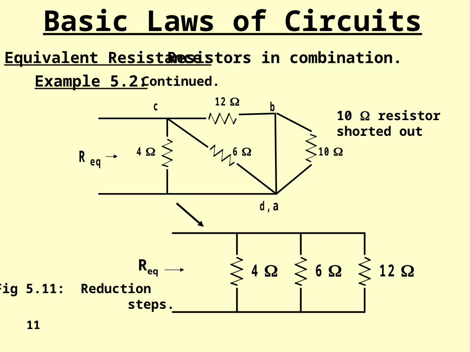
1 2 6 4 Fig 5.11: Reduction steps.
Req
10 resistorshorted out
Basic Laws of CircuitsEquivalent Resistance: Resistors in combination.
Example 5.2: Continued.
11
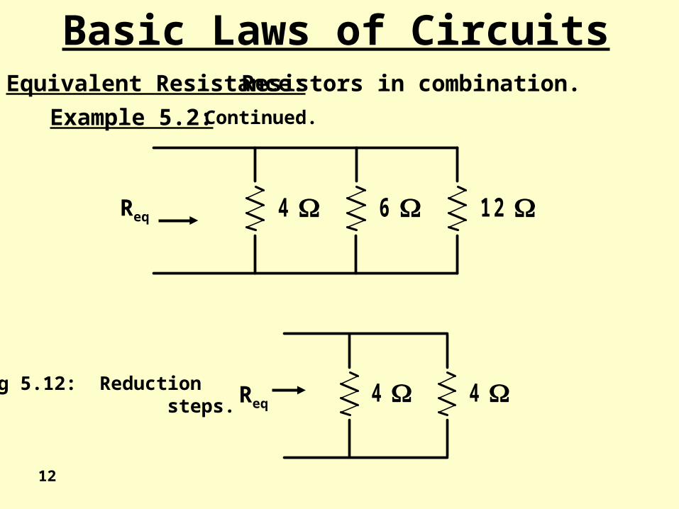
Basic Laws of CircuitsEquivalent Resistance: Resistors in combination.
Example 5.2: Continued.
4 4
1 2 6 4
Fig 5.12: Reduction steps.
Req
Req
12
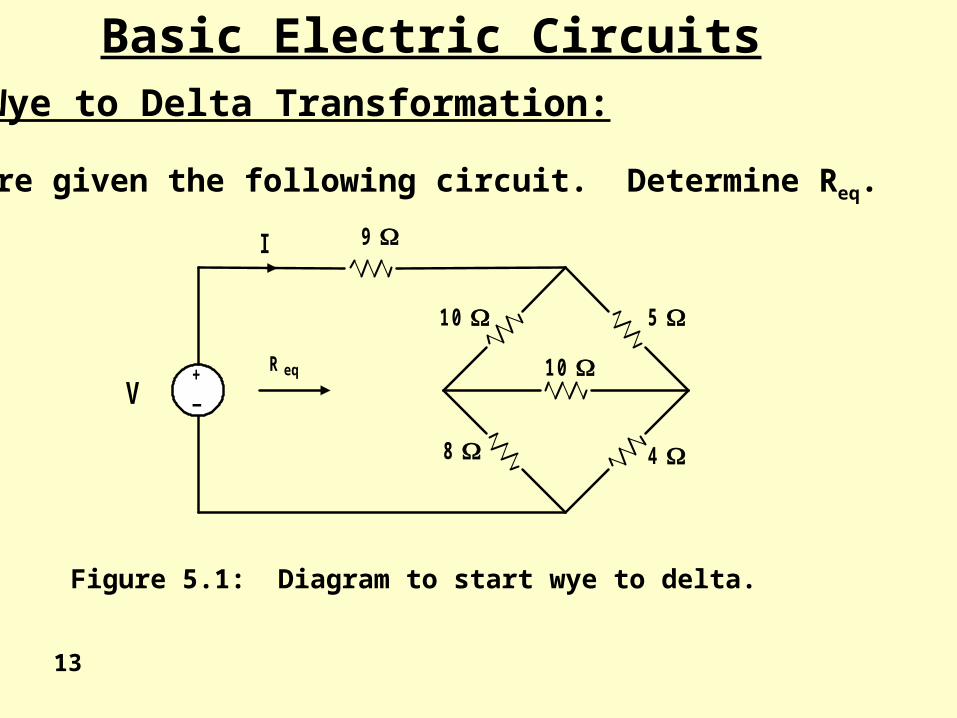
Basic Electric CircuitsWye to Delta Transformation:
You are given the following circuit. Determine Req.
9
1 0 5
8 4
V+_
R eq 1 0
I
Figure 5.1: Diagram to start wye to delta.
13
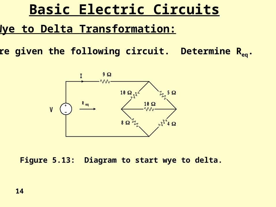
Basic Electric CircuitsWye to Delta Transformation:
You are given the following circuit. Determine Req.
9
1 0 5
8 4
V+_
R eq 1 0
I
Figure 5.13: Diagram to start wye to delta.
14
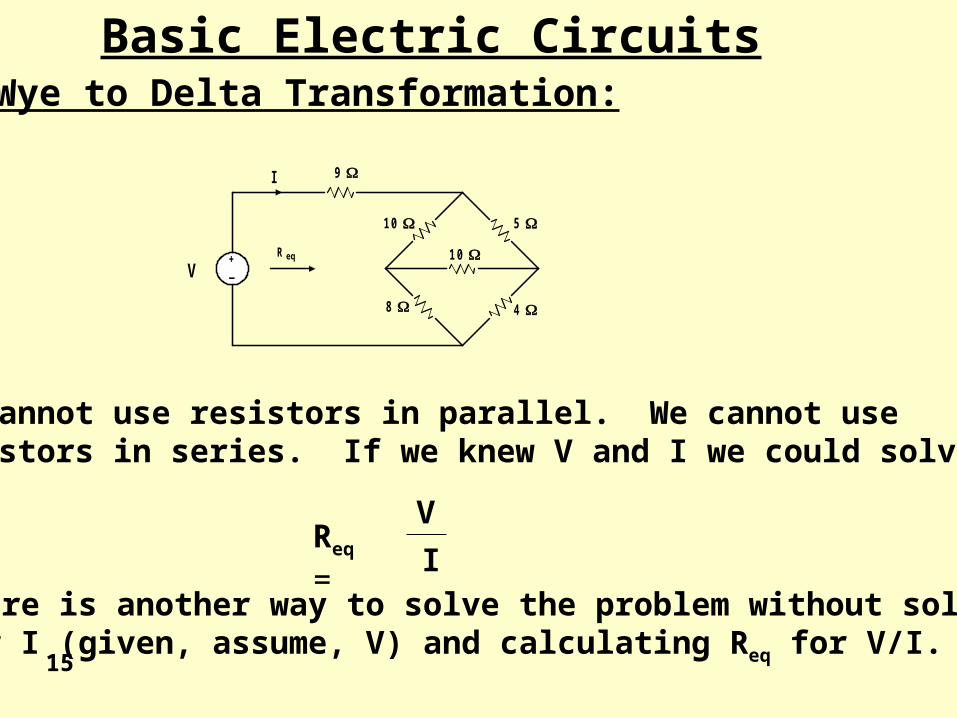
Basic Electric CircuitsWye to Delta Transformation:
9
1 0 5
8 4
V+_
R eq 1 0
I
We cannot use resistors in parallel. We cannot useresistors in series. If we knew V and I we could solve
Req =V
I
There is another way to solve the problem without solvingfor I (given, assume, V) and calculating Req for V/I.
15
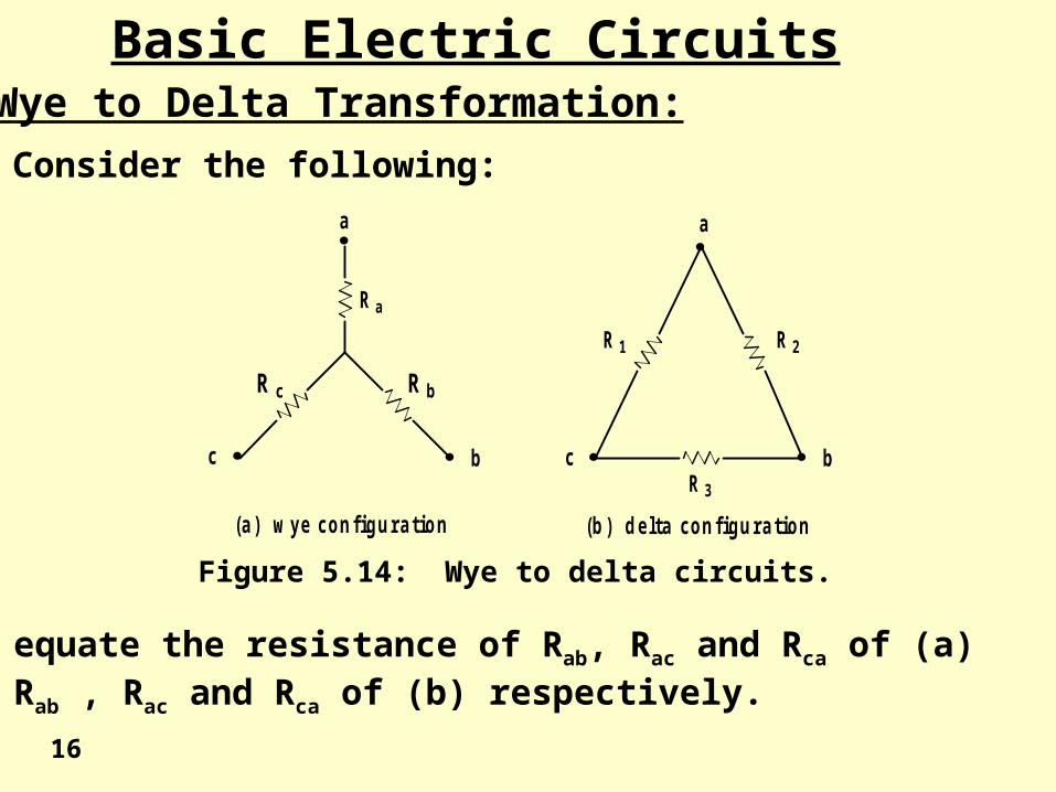
Basic Electric CircuitsWye to Delta Transformation:
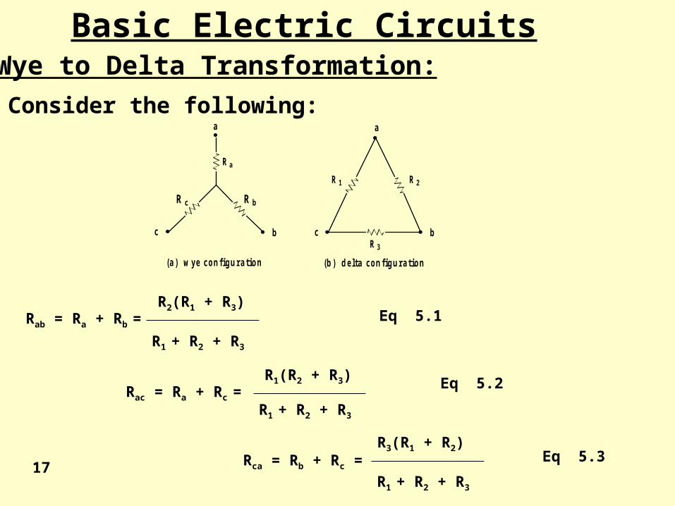
Consider the following:
a
bc
a
bc
R a
R bR c
R 1 R 2
R 3
(a ) w ye c o n fig u ra tio n (b ) d e lta c o n fig u ra tio n
We equate the resistance of Rab, Rac and Rca of (a)to Rab , Rac and Rca of (b) respectively.
Figure 5.14: Wye to delta circuits.
16
Basic Electric CircuitsWye to Delta Transformation:
Consider the following:
a
bc
a
bc
R a
R bR c
R 1 R 2
R 3
(a ) w ye c o n fig u ra tio n (b ) d e lta c o n fig u ra tio n
Rab = Ra + Rb =
Rac = Ra + Rc =
Rca = Rb + Rc =
R1 + R2 + R3
R1 + R2 + R3
R1 + R2 + R3
R2(R1 + R3)
R1(R2 + R3)
R3(R1 + R2)
Eq 5.1
Eq 5.2
Eq 5.317
Basic Electric CircuitsWye to Delta Transformation:
Consider the following:
a
bc
a
bc
R a
R bR c
R 1 R 2
R 3
(a ) w ye c o n fig u ra tio n (b ) d e lta c o n fig u ra tio n
a
accbba
c
accbba
b
accbba
R
RRRRRRR
R
RRRRRRR
R
RRRRRRR
3
2
1
321
31
321
32
321
21
RRR
RRR
RRR
RRR
RRR
RRR
c
b
a
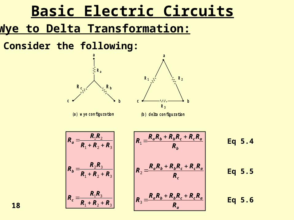
Eq 5.4
Eq 5.5
Eq 5.618
19
a
accbba
c
accbba
b
accbba
R
RRRRRRR
R
RRRRRRR
R
RRRRRRR
3
2
1
321
31
321
32
321
21
RRR
RRR
RRR
RRR
RRR
RRR
c
b
a
Eq 5.4
Eq 5.5
Eq 5.6
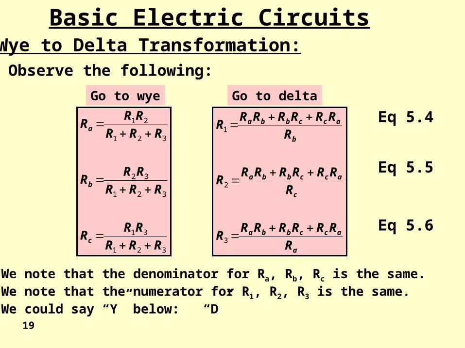
Basic Electric CircuitsWye to Delta Transformation:Observe the following:
We note that the denominator for Ra, Rb, Rc is the same.We note that the numerator for R1, R2, R3 is the same.We could say “Y” below: “D”
Go to deltaGo to wye
20
Basic Electric CircuitsWye to Delta Transformation:
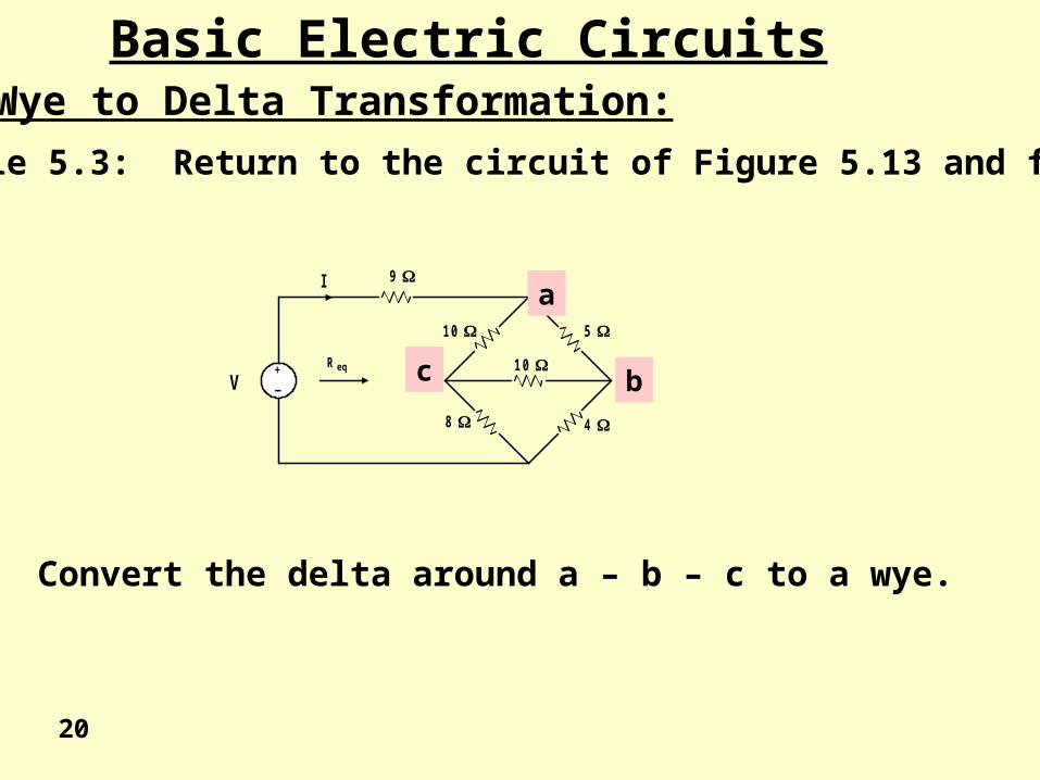
Example 5.3: Return to the circuit of Figure 5.13 and find Req.
9
1 0 5
8 4
V+_
R eq 1 0
Ia
bc
Convert the delta around a – b – c to a wye.
Basic Electric CircuitsWye to Delta Transformation:
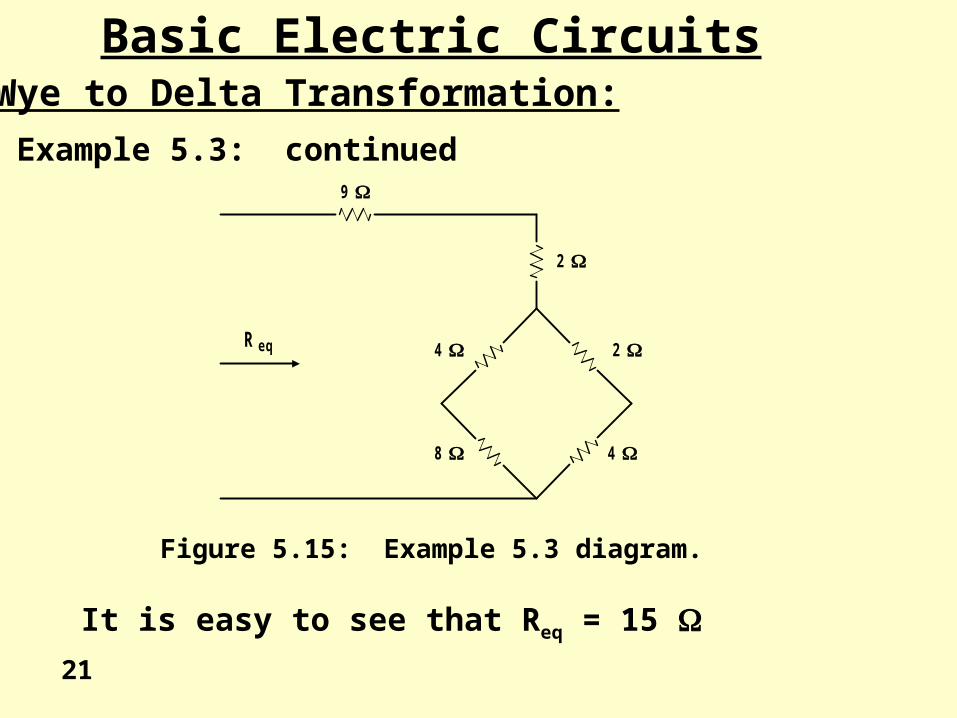
Example 5.3: continued
2
2 4
4 8
9
R e q
21
Figure 5.15: Example 5.3 diagram.
It is easy to see that Req = 15
22
Basic Electric CircuitsWye to Delta Transformation:
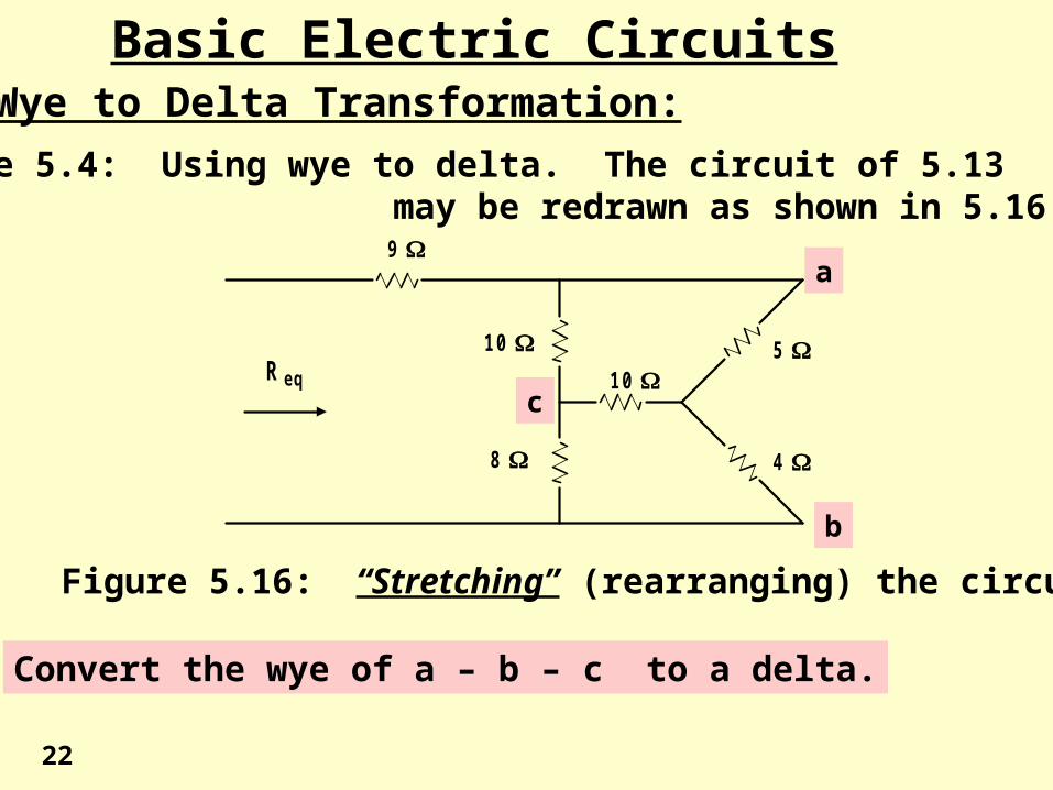
Example 5.4: Using wye to delta. The circuit of 5.13 may be redrawn as shown in 5.16.
R e q
9
1 0 5
8 4
1 0
a
b
c
Figure 5.16: “Stretching” (rearranging) the circuit.
Convert the wye of a – b – c to a delta.
Basic Electric CircuitsWye to Delta Transformation:
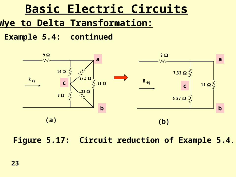
Example 5.4: continued
R e q
9
1 0
8
1 1 2 7 .5
2 2
a
b
c R e q
9
7 .3 3
5 .8 7
1 1
Figure 5.17: Circuit reduction of Example 5.4.
(a) (b)
23
a
b
c
Basic Electric CircuitsWye to Delta Transformation:
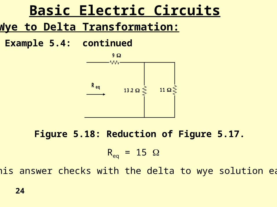
Example 5.4: continued
R e q
9
1 1 1 3 .2
Figure 5.18: Reduction of Figure 5.17.
Req = 15
This answer checks with the delta to wye solution earlier.
24
circuits
End of Lesson 5
Basic Laws of Circuits
Equivalent Resistance