Embed Size (px)
Citation preview

Lesson 8: Introduction to DatabasesE-R Data Modeling
Lesson 8 / Page 2AE3B33OSD Silberschatz, Korth, Sudarshan S. ©2007
Contents
� Introduction to Databases� Abstraction, Schemas, and Views� Data Models� Database Management System (DBMS) Components� Entity – Relationship Data Model� E-R Diagrams� Database Design Issues� Constraints� Converting E-R Model to Schemas
Lesson 8 / Page 3AE3B33OSD Silberschatz, Korth, Sudarshan S. ©2007
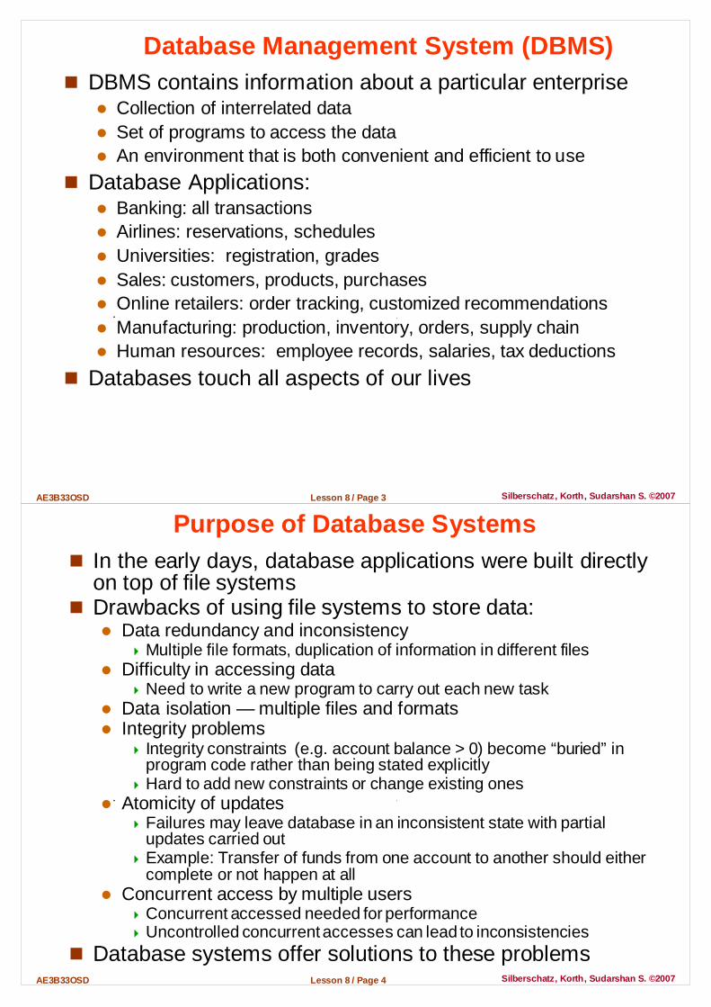
Database Management System (DBMS)� DBMS contains information about a particular enterprise
� Collection of interrelated data� Set of programs to access the data � An environment that is both convenient and efficient to use
� Database Applications:� Banking: all transactions� Airlines: reservations, schedules� Universities: registration, grades� Sales: customers, products, purchases� Online retailers: order tracking, customized recommendations� Manufacturing: production, inventory, orders, supply chain� Human resources: employee records, salaries, tax deductions
� Databases touch all aspects of our lives
Lesson 8 / Page 4AE3B33OSD Silberschatz, Korth, Sudarshan S. ©2007
Purpose of Database Systems� In the early days, database applications were built directly
on top of file systems� Drawbacks of using file systems to store data:
� Data redundancy and inconsistency� Multiple file formats, duplication of information in different files
� Difficulty in accessing data � Need to write a new program to carry out each new task
� Data isolation — multiple files and formats� Integrity problems
� Integrity constraints (e.g. account balance > 0) become “buried” in program code rather than being stated explicitly
� Hard to add new constraints or change existing ones� Atomicity of updates
� Failures may leave database in an inconsistent state with partial updates carried out
� Example: Transfer of funds from one account to another should either complete or not happen at all
� Concurrent access by multiple users� Concurrent accessed needed for performance� Uncontrolled concurrent accesses can lead to inconsistencies
� Database systems offer solutions to these problems

Lesson 8 / Page 5AE3B33OSD Silberschatz, Korth, Sudarshan S. ©2007
Levels of Abstraction� Physical level: describes how a record (e.g., customer) is
stored.� Logical level: describes data stored in database, and the
relationships among the data.type customer = record
customer_id : string;customer_name : string;customer_street : string;customer_zip : integer;
end ;
� View level:application programs hide details of data types. Views can also hide information (such as an employee’s salary) for security and confidentiality purposes.
View 1 View 2 View n...
View level
Logical level
Physical level
Lesson 8 / Page 6AE3B33OSD Silberschatz, Korth, Sudarshan S. ©2007
Instances and Schemas
� Schema – the logical structure of the database � Example: The database consists of information about a set of customers
and accounts and the relationship between them� Analogous to type information of a variable in a program� Physical schema : database design at the physical level� Logical schema : database design at the logical level
� Instance – the actual content of the database at a particular point in time � Analogous to the value of a variable
� Physical Data Independence – the ability to modify the physical schema without changing the logical schema� Applications depend on the logical schema� In general, the interfaces between the various levels and components
should be well defined so that changes in some parts do not seriously influence others.

Lesson 8 / Page 7AE3B33OSD Silberschatz, Korth, Sudarshan S. ©2007
Data Models� A collection of tools for describing
� Data � Data relationships� Data semantics� Data constraints
� Relational model� Entity-Relationship data model
� mainly for database design� designing the database schema
� Object-based data models � Object-oriented and Object-relational databases
� Semistructured data model (XML)� Other older models:
� Network model � Hierarchical model
Lesson 8 / Page 8AE3B33OSD Silberschatz, Korth, Sudarshan S. ©2007
Data Oriented Languages� Data Manipulation Languages (DML)
� Language for accessing and manipulating the data organized by the appropriate data model (also known as query language)
� Two classes of languages � Procedural – user specifies what data is required and how to get
those data � Declarative (nonprocedural) – user specifies what data is required
without specifying how to get those data� SQL is the most widely used query language
� Data Definition Language (DDL)� Specification of the database schema definition
Example:create table account (account_number: char (10), balance: integer )
� DDL compiler generates a set of tables stored in a data dictionary� Data dictionary contains metadata (i.e., data about data)
� Database schema � Data storage and definition of data
– Specifies the storage structure and access methods used� Integrity constraints
– Domain constraints– Referential integrity (references constraint in SQL)– Assertions
� Authorization
Lesson 8 / Page 9AE3B33OSD Silberschatz, Korth, Sudarshan S. ©2007
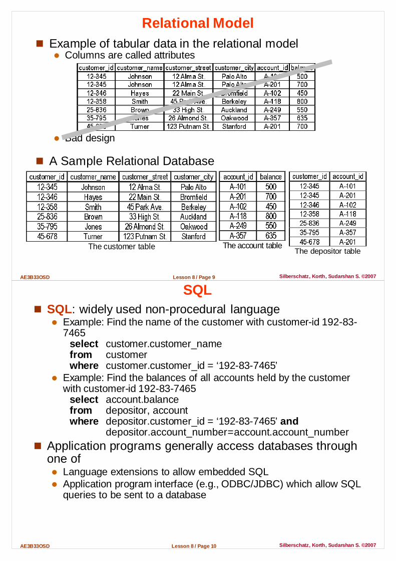
Relational Model� Example of tabular data in the relational model
� Columns are called attributes
� Bad design
� A Sample Relational Database
The customer table
The account table
The depositor table
Lesson 8 / Page 10AE3B33OSD Silberschatz, Korth, Sudarshan S. ©2007
SQL� SQL: widely used non-procedural language
� Example: Find the name of the customer with customer-id 192-83-7465
select customer.customer_namefrom customerwhere customer.customer_id = ‘192-83-7465’
� Example: Find the balances of all accounts held by the customer with customer-id 192-83-7465
select account.balancefrom depositor, accountwhere depositor.customer_id = ‘192-83-7465’ and
depositor.account_number = account.account_number� Application programs generally access databases through
one of� Language extensions to allow embedded SQL� Application program interface (e.g., ODBC/JDBC) which allow SQL
queries to be sent to a database
Lesson 8 / Page 11AE3B33OSD Silberschatz, Korth, Sudarshan S. ©2007
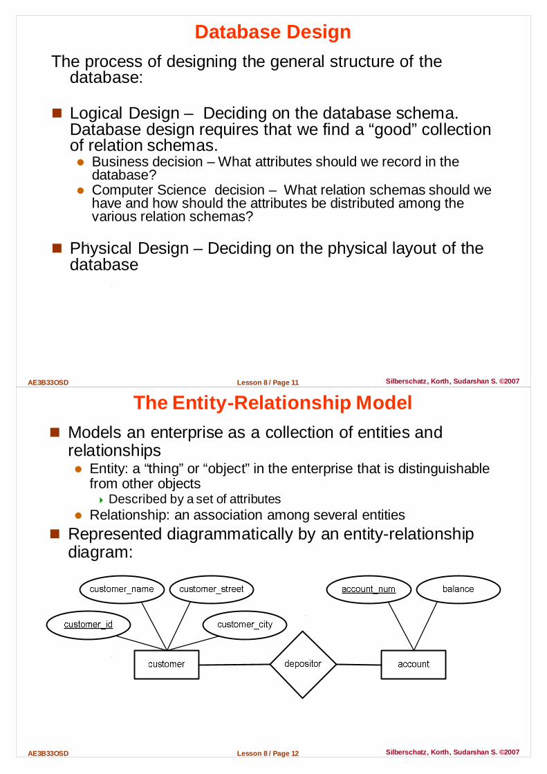
Database DesignThe process of designing the general structure of the
database:
� Logical Design – Deciding on the database schema. Database design requires that we find a “good” collection of relation schemas.� Business decision – What attributes should we record in the
database?� Computer Science decision – What relation schemas should we
have and how should the attributes be distributed among the various relation schemas?
� Physical Design – Deciding on the physical layout of the database
Lesson 8 / Page 12AE3B33OSD Silberschatz, Korth, Sudarshan S. ©2007
The Entity-Relationship Model� Models an enterprise as a collection of entities and
relationships� Entity: a “thing” or “object” in the enterprise that is distinguishable
from other objects� Described by a set of attributes
� Relationship: an association among several entities� Represented diagrammatically by an entity-relationship
diagram:

Lesson 8 / Page 13AE3B33OSD Silberschatz, Korth, Sudarshan S. ©2007
Object-Relational Data Models� Extend the relational data model by including object
orientation and constructs to deal with added data types.
� Allow attributes of tuples to have complex types, including non-atomic values such as nested relations.
� Preserve relational foundations, in particular the declarative access to data, while extending modeling power.
� Provide upward compatibility with existing relational languages.
Lesson 8 / Page 14AE3B33OSD Silberschatz, Korth, Sudarshan S. ©2007
XML: Extensible Markup Language
� Defined by the WWW Consortium (W3C)� Originally intended as a document markup language not
a database language� The ability to specify new tags, and to create nested tag
structures made XML a great way to exchange data, not just documents
� XML has become the basis for all new generation data interchange formats.
� A wide variety of tools is available for parsing, browsing and querying XML documents/data

Lesson 8 / Page 15AE3B33OSD Silberschatz, Korth, Sudarshan S. ©2007
Storage Management� Storage manager is a program module that provides the
interface between the low-level data stored in the database and the application programs and queries submitted to the system.
� The storage manager is responsible to the following tasks: � Interaction with the file manager � Efficient storing, retrieving and updating of data
� Issues:� Storage access� File organization� Indexing and hashing
Lesson 8 / Page 16AE3B33OSD Silberschatz, Korth, Sudarshan S. ©2007
Query Processing
1. Parsing and translation
2. Optimization3. Evaluation
� Alternative ways of evaluating a given query� Equivalent expressions� Different algorithms for each operation
� Cost difference between a good and a bad way of evaluating a query can be enormous
� Need to estimate the cost of operations� Depends critically on statistical information about relations which
the database must maintain� Need to estimate statistics for intermediate results to compute cost
of complex expressions

Lesson 8 / Page 17AE3B33OSD Silberschatz, Korth, Sudarshan S. ©2007
Transaction Management
� A transaction is a collection of operations that performs a single logical function in a database application� E.g., transfer a given amount from one account to another
� Transaction-management component ensures that the database remains in a consistent (correct) state despite system failures (e.g., power failures and operating system crashes) and transaction failures� E.g., tries to plan (schedule) transactions to keep consistency
� Concurrency-control manager controls the interaction among the concurrent transactions, to ensure the consistency of the database� E.g., has to resolve deadlock states
Lesson 8 / Page 18AE3B33OSD Silberschatz, Korth, Sudarshan S. ©2007
Database UsersUsers are differentiated by the way they are expected to
interact with the system� Application programmers – interact with system
through DML calls� Sophisticated users – form requests in a database
query language� Specialized users – write specialized database
applications that do not fit into the traditional data processing framework
� Naive users – invoke one of the permanent application programs that have been written previously by an application programmer� Examples: E-shopping, Internet banking, University clerical staff
accessing student database
Lesson 8 / Page 19AE3B33OSD Silberschatz, Korth, Sudarshan S. ©2007
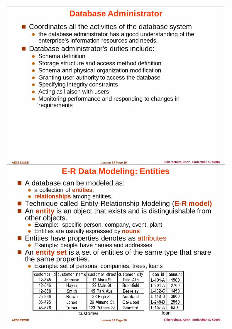
Database Administrator
� Coordinates all the activities of the database system� the database administrator has a good understanding of the
enterprise’s information resources and needs.� Database administrator's duties include:
� Schema definition� Storage structure and access method definition� Schema and physical organization modification� Granting user authority to access the database� Specifying integrity constraints� Acting as liaison with users� Monitoring performance and responding to changes in
requirements
Lesson 8 / Page 20AE3B33OSD Silberschatz, Korth, Sudarshan S. ©2007
E-R Data Modeling: Entities� A database can be modeled as:
� a collection of entities,� relationships among entities.
� Technique called Entity-Relationship Modeling (E-R model)� An entity is an object that exists and is distinguishable from
other objects.� Example: specific person, company, event, plant� Entities are usually expressed by nouns
� Entities have properties denotes as attributes� Example: people have names and addresses
� An entity set is a set of entities of the same type that share the same properties.� Example: set of persons, companies, trees, loans
customer
loan

Lesson 8 / Page 21AE3B33OSD Silberschatz, Korth, Sudarshan S. ©2007
Attributes� An entity is represented by a set of attributes, that is
descriptive properties possessed by all members of an entity set.
� Domain – the set of permitted values for each attribute � Attribute types:
� Simple and composite attributes� Single-valued and multi-valued attributes
� Example: multivalued attribute: phone_numbers� Derived attributes
� Can be computed from other attributes� Example: age, given date_of_birth
Example: customer = (customer_id, customer_name,
customer_street, customer_city )loan = (loan_number, amount )
Lesson 8 / Page 22AE3B33OSD Silberschatz, Korth, Sudarshan S. ©2007
Composite Attributes
Compositeattributes
Componentattributes

Lesson 8 / Page 23AE3B33OSD Silberschatz, Korth, Sudarshan S. ©2007
Data Modeling: Relationships� A relationship creates an association among several
entitiesExample:
Hayes deposits to A-102customer entity relationship account entity
� Relationships are often expressed by verb phrases
� A relationship set is a set of associations between two (or more) entity sets� mathematical relation among n ≥ 2 entities, each taken from an
entity set{(e1, e2, … en) | e1 ∈ E1, e2 ∈ E2, …, en ∈ En}
where (e1, e2, …, en) is a relationship� Example:
(Hayes, A-102) ∈ deposits_to
Lesson 8 / Page 24AE3B33OSD Silberschatz, Korth, Sudarshan S. ©2007
Relationship Set owe
customer
loan
relationship setowe
� Relationship sets are expressed by tables� Relationship sets can have
attributes� Example: Date of last access
owe

Lesson 8 / Page 25AE3B33OSD Silberschatz, Korth, Sudarshan S. ©2007
Degree of a Relationship Set� Refers to number of entity sets that participate in a
relationship� Relationship sets that involve two entity sets are binary
(or degree two). � Most relationship sets in a database system are binary.
� Relationship sets may involve more than two entity sets� Example: Suppose employees of a bank may have jobs
(responsibilities) at multiple branches, with different jobs at different branches. Then there is a ternary relationship set between entity sets employee, job, and branch
� Relationships between more than two entity sets are rare. Most relationships are binary� We will mostly speak about binary relationships
Lesson 8 / Page 26AE3B33OSD Silberschatz, Korth, Sudarshan S. ©2007
Relationship Mapping Cardinality� Cardinality expresses the number of entities to which
another entity can be associated via a relationship set� Most useful in describing binary relationship sets� For a binary relationship set the mapping cardinality must be
one of the following types:
one to one one to many
many to one many to many
Note: Some elements in A and B may not be mapped to any elements in the other set

Lesson 8 / Page 27AE3B33OSD Silberschatz, Korth, Sudarshan S. ©2007
Keys� A super key of an entity set is a set of one or more
attributes whose values uniquely determine each entity.� A candidate key of an entity set is a minimal super key
� Customer_id is candidate key of customer� account_number is candidate key of account
� Although several candidate keys may exist, one of the candidate keys is selected to be the primary key
� The combination of primary keys of the participating entity sets forms a super key of a relationship set� (customer_id, account_number) is the super key of depositor� NOTE: this means a pair of entity sets can have at most one
relationship in a particular relationship set. � Example: if we wish to track all access_dates to each account by
each customer, we cannot assume a relationship for each access. We can use a multivalued attribute though
� Must consider the mapping cardinality of the relationship set when deciding what are the candidate keys
� Need to consider semantics of relationship set in selecting the primary key in case of more than one candidate key
Lesson 8 / Page 28AE3B33OSD Silberschatz, Korth, Sudarshan S. ©2007
E-R Diagrams
� Rectangles represent entity sets.� Diamonds represent relationship sets.� Lines link attributes to entity sets and entity sets to
relationship sets.� Ellipses represent attributes
� Double ellipses represent multivalued attributes.� Dashed ellipses denote derived attributes.
� Underline indicates primary key attributes

Lesson 8 / Page 29AE3B33OSD Silberschatz, Korth, Sudarshan S. ©2007
E-R Diagram With Composite, Multivalued, and Derived Attributes
Lesson 8 / Page 30AE3B33OSD Silberschatz, Korth, Sudarshan S. ©2007
Relationship Sets with Attributes

Lesson 8 / Page 31AE3B33OSD Silberschatz, Korth, Sudarshan S. ©2007
Roles� Entity sets of a relationship need not be distinct� The labels “manager” and “worker” are called roles
� they specify how employee entities interact via the works_for relationship set.
� Roles are indicated in E-R diagrams by labeling the lines that connect diamonds to rectangles.
� Role labels are optional, and are used to clarify semantics of the relationship
Lesson 8 / Page 32AE3B33OSD Silberschatz, Korth, Sudarshan S. ©2007
Cardinality Constraints
� We express cardinality constraints by drawing either a directed line (→), signifying “one,” or an undirected line (—), signifying “many,” between the relationship set and the entity set.
� One-to-one relationship:� A customer is associated with at most one loan via the
relationship borrower� A loan is associated with at most one customer via borrower
Lesson 8 / Page 33AE3B33OSD Silberschatz, Korth, Sudarshan S. ©2007
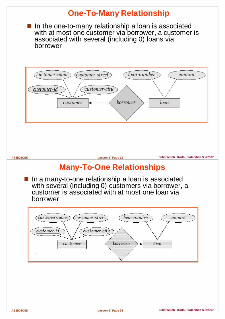
One-To-Many Relationship
� In the one-to-many relationship a loan is associated with at most one customer via borrower, a customer is associated with several (including 0) loans via borrower
Lesson 8 / Page 34AE3B33OSD Silberschatz, Korth, Sudarshan S. ©2007
Many-To-One Relationships� In a many-to-one relationship a loan is associated
with several (including 0) customers via borrower, a customer is associated with at most one loan via borrower

Lesson 8 / Page 35AE3B33OSD Silberschatz, Korth, Sudarshan S. ©2007
Many-To-Many Relationship� A customer is associated with several (possibly 0) loans via
borrower� A loan is associated with several (possibly 0) customers via
borrower
Lesson 8 / Page 36AE3B33OSD Silberschatz, Korth, Sudarshan S. ©2007
Participation of an Entity Set in a Relationship Se t
� Total participation (indicated by double line): every entity in the entity set participates in at least one relationship in the relationship set� E.g. participation of loan in borrower is total
� every loan must have a customer associated to it via borrower� Partial participation: some entities may not participate in
any relationship in the relationship set� Example: participation of customer in borrower is partial

Lesson 8 / Page 37AE3B33OSD Silberschatz, Korth, Sudarshan S. ©2007
Alternative Notation for Cardinality Limits
� Cardinality limits can also express participation constraints
Lesson 8 / Page 38AE3B33OSD Silberschatz, Korth, Sudarshan S. ©2007
Design Issues� Use of entity sets vs. attributes
� Choice mainly depends on the structure of the enterprise being modeled, and on the semantics associated with the attribute in question.
� Use of entity sets vs. relationship sets� Possible guideline is to designate a relationship set to describe an
action that occurs between entities� Binary versus n-ary relationship sets
� Although it is possible to replace any non-binary (n-ary, for n > 2) relationship set by a number of distinct binary relationship sets, a n-ary relationship set shows more clearly that several entities participate in a single relationship.
� Placement of relationship attributes� Is it reasonable to add the intended attribute to the relationship
set?

Lesson 8 / Page 39AE3B33OSD Silberschatz, Korth, Sudarshan S. ©2007
Binary Vs. Non-Binary Relationships
� Some relationships that appear to be non-binary may be better represented using binary relationships� E.g. A ternary relationship parents, relating a child to his/her
father and mother, is best replaced by two binary relationships,father and mother� Using two binary relationships allows partial information (e.g. only
mother being know)� But there are some relationships that are naturally non-binary
� Example: works_on
Lesson 8 / Page 40AE3B33OSD Silberschatz, Korth, Sudarshan S. ©2007
Converting Non-Binary Relationships to Binary� In general, any non-binary relationship can be represented
using binary relationships by creating an artificial entity set.� Replace R between entity sets A, B and C by an entity set E, and
three relationship sets: 1. RA, relating E and A 2.RB, relating E and B3. RC, relating E and C
� Create a special identifying attribute for E� Add any attributes of R to E � For each relationship (ai , bi , ci) in R, create
1. a new entity ei in the entity set E 2. add (ei , ai ) to RA
3. add (ei , bi ) to RB 4. add (ei , ci ) to RC
Lesson 8 / Page 41AE3B33OSD Silberschatz, Korth, Sudarshan S. ©2007
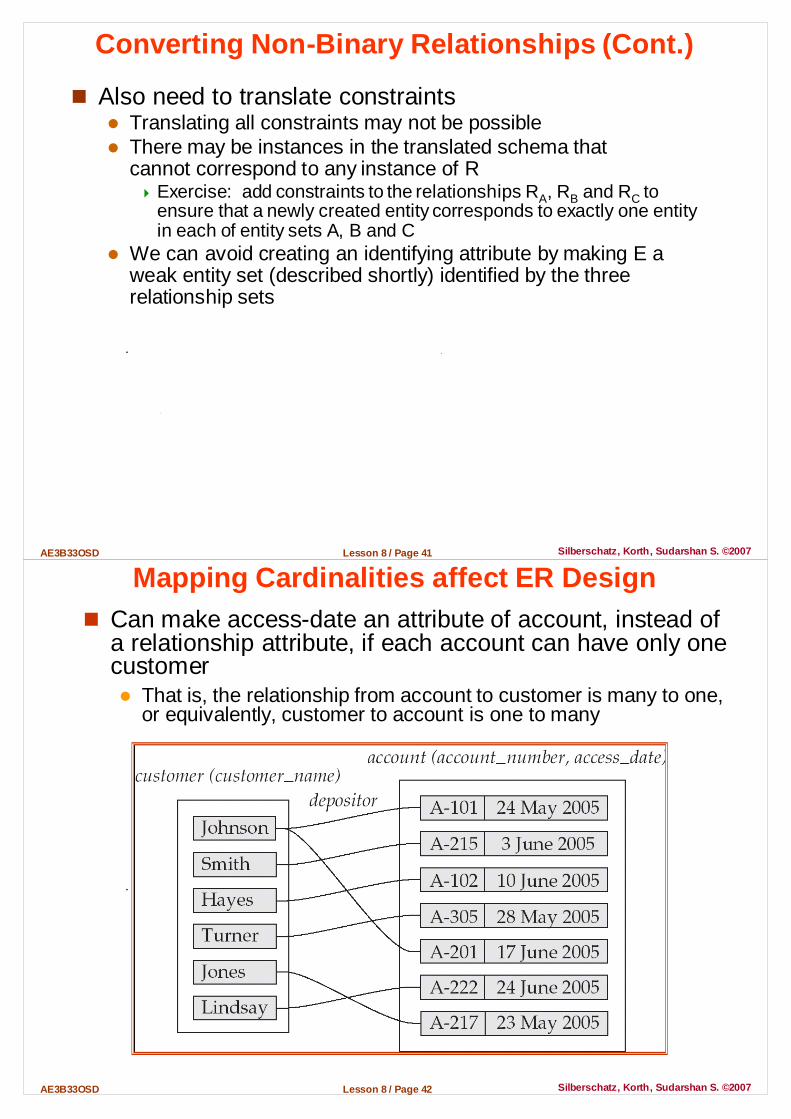
Converting Non-Binary Relationships (Cont.)
� Also need to translate constraints� Translating all constraints may not be possible� There may be instances in the translated schema that
cannot correspond to any instance of R� Exercise: add constraints to the relationships RA, RB and RC to
ensure that a newly created entity corresponds to exactly one entity in each of entity sets A, B and C
� We can avoid creating an identifying attribute by making E a weak entity set (described shortly) identified by the three relationship sets
Lesson 8 / Page 42AE3B33OSD Silberschatz, Korth, Sudarshan S. ©2007
Mapping Cardinalities affect ER Design� Can make access-date an attribute of account, instead of
a relationship attribute, if each account can have only one customer � That is, the relationship from account to customer is many to one,
or equivalently, customer to account is one to many

Lesson 8 / Page 43AE3B33OSD Silberschatz, Korth, Sudarshan S. ©2007
Weak Entity Sets� An entity set that does not have a primary key is referred to
as a weak entity set .� The existence of a weak entity set depends on the existence of an
identifying entity set� It must relate to the identifying entity set via a total, one-to-many
relationship set from the identifying to the weak entity set� Identifying relationship depicted using a double diamond
� The discriminator (or partial key) of a weak entity set is the set of attributes that distinguishes among all the entities of a weak entity set.
� The primary key of a weak entity set is formed by the primary key of the strong entity set on which the weak entity set is existence dependent, plus the weak entity set’s discriminator.� We depict a weak entity set by double rectangles.
� We underline the discriminator of a weak entity set with a dashed line.� payment_number – discriminator of the payment entity set � Primary key for payment – (loan_number, payment_number)
Lesson 8 / Page 44AE3B33OSD Silberschatz, Korth, Sudarshan S. ©2007
E-R Design Decisions
� The use of an attribute or entity set to represent an object.
� Whether a real-world concept is best expressed by an entity set or a relationship set.
� The use of a ternary relationship versus a pair of binary relationships.
� The use of a strong or weak entity set.� The use of specialization/generalization – contributes
to modularity in the design.� The use of aggregation – can treat the aggregate entity
set as a single unit without concern for the details of its internal structure.

Lesson 8 / Page 45AE3B33OSD Silberschatz, Korth, Sudarshan S. ©2007
E-R Diagram for a Banking Enterprise
Lesson 8 / Page 46AE3B33OSD Silberschatz, Korth, Sudarshan S. ©2007
Summary of Symbols Used in E-R Notation

Lesson 8 / Page 47AE3B33OSD Silberschatz, Korth, Sudarshan S. ©2007
Reduction to Relation Schemas� Primary keys allow entity sets and relationship sets to be
expressed uniformly as relation schemas that represent the contents of the database.� A database which conforms to an E-R diagram can be represented
by a collection of schemas.� For each entity set and relationship set there is a unique schema
that is assigned the name of the corresponding entity set or relationship set.
� Each schema has a number of columns (generally corresponding to attributes), which have unique names
� A strong entity set reduces to a schema with the same attributes.
� A weak entity set becomes a table that includes a column for the primary key of the identifying strong entity set
payment = (loan_number, payment_number,payment_date, payment_amount)
� A many-to-many relationship set is represented as a schema with attributes for the primary keys of the two participating entity sets � and perhaps any descriptive attributes of the relationship set. � Example: schema for relationship set borrower
borrower = (customer_id, loan_number)
Lesson 8 / Page 48AE3B33OSD Silberschatz, Korth, Sudarshan S. ©2007
� Many-to-one and one-to-many relationship sets that are total on the many-side can be represented by adding an extra attribute to the “many” side, containing the primary key of the “one” side� Example: Instead of creating a schema for relationship set
account_branch, add an attribute branch_name to the schema arising from entity set account
� For one-to-one relationship sets, either side can be chosen to act as the “many” side� That is, extra attribute can be added to either of the tables
corresponding to the two entity sets
Redundancy of Schemas
Lesson 8 / Page 49AE3B33OSD Silberschatz, Korth, Sudarshan S. ©2007
Composite and Multivalued Attributes� Composite attributes are flattened out by creating a
separate attribute for each component attribute� Example: given entity set customer with composite attribute name
with component attributes first_name and last_name the schema corresponding to the entity set has two attributes
name.first_name and name.last_name� A multivalued attribute M of an entity E is represented by
a separate schema EM� Schema EM has attributes corresponding to the primary key of E
and an attribute corresponding to multivalued attribute M� Example: Multivalued attribute dependent_names of employee is
represented by a schema:employee_dependent_names = ( employee_id, dname)
� Each value of the multivalued attribute maps to a separate tuple of the relation on schema EM� For example, an employee entity with primary key 123-45-6789 and
dependents Jack and Jane maps to two tuples: (123-45-6789 , Jack) and (123-45-6789 , Jane)
End of Lesson 8
Questions?