Embed Size (px)
Citation preview
Lessons from a Recent Space Truss Collapse
Ariel Hanaor
National Building Research Institute, The Technion, Israel Institute of Technology Technion City, Haifa 32000, Israel.
Ph.: –972-4-8293039, Fax: –972-4-8324534, E-mail: [email protected]
ABSTRACT
The investigation into the collapse of the 15th Macabia footbridge in Israel on July 14, 1997 revealed major flaws at all levels. At the technical level, these flaws included numerous design and construction errors, several of which could have led, independently, to the collapse of the bridge. The paper is concerned primarily with the phenomenon of joint instability, to which the joining system employed is susceptible. Low rotational rigidity of joints in space trusses can result in the formation of plastic hinges at the joints which leads to premature compression member failure and to substantial reductions in load carrying capacity of the truss. This phenomenon, which had been observed in several studies in the past, was exacerbated in the present case by the introduction of substantial camber to a joining system specifically designed for planar configurations, by the subjection of compression members to flexure, and by eccentric connection of supports. Evidence from the site indicates that joint rotation was ubiquitous in the failure mechanism, even if it was not the actual trigger of collapse. The paper stresses the importance of designing rigidity into prefabricated space truss systems and the need for the formulation of codes of practice for the design of space trusses. In particular, analytical models are required, which reliably model the phenomenon, and which can be simply and easily incorporated in standard design practice.
BACKGROUND
General layout and structural details
On the evening of July 14, 1997, a temporary footbridge carrying athletes to the opening ceremony of the 15th Macabia sporting event in Israel collapsed, killing one person, injuring 60 and leading to the subsequent death of three more. All casualties were members of the Australian athletic team. The 34 m long bridge, spanning 25 m collapsed under a load of no more than one hundred people, even though the design called for four-fold this load. The general layout of the site is shown in Figure1.
The structure supporting the timber deck was a double-layer square-on-square offset grid totaling 14 lengthwise by two widthwise modules of approximately 2.5x2.5 m (average). A line diagram of the truss, with assumed supports is shown in Figure 2 and an elevation is shown in Figure 3. The elevation also shows the intended, approximate layout of the supports. The truss had a camber of approximately 2.6 m and cables connected the extreme support nodes on the south side with the intermediate support nodes on the north side of the bridge. The cables were introduced as a “safety measure” but did not feature in the load-bearing scheme. The analysis showed that the load was supported primarily by the truss, with cables contributing verylittle.
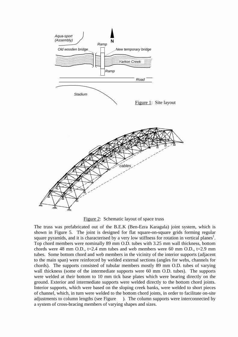
The truss was prefabricated out of the B.E.K (Ben-Ezra Karagula) joint system, which is shown in Figure 5. The joint is designed for flat square-on-square grids forming regular square pyramids, and it is characterised by a very low stiffness for rotation in vertical planes1. Top chord members were nominally 89 mm O.D. tubes with 3.25 mm wall thickness, bottom chords were 48 mm O.D., t=2.4 mm tubes and web members were 60 mm O.D., t=2.9 mm tubes. Some bottom chord and web members in the vicinity of the interior supports (adjacent to the main span) were reinforced by welded external sections (angles for webs, channels for chords). The supports consisted of tubular members mostly 89 mm O.D. tubes of varying wall thickness (some of the intermediate supports were 60 mm O.D. tubes). The supports were welded at their bottom to 10 mm tick base plates which were bearing directly on the ground. Exterior and intermediate supports were welded directly to the bottom chord joints. Interior supports, which were based on the sloping creek banks, were welded to short pieces of channel, which, in turn were welded to the bottom chord joints, in order to facilitate on-site adjustments to column lengths (see Figure ). The column supports were interconnected by a system of cross-bracing members of varying shapes and sizes.
Figure 2: Schematic layout of space truss
cables
Aqua-sport (Assembly)
Old wooden bridge New temporary bridge
N
Road
Yarkon Creek
Figure 1: Site layout
Stadium
Ramp
Ramp
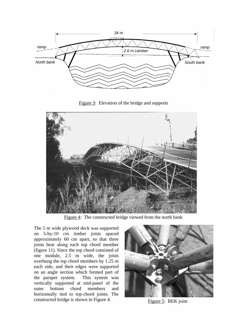
The 5 m wide plywood deck was supported on 5-by-10 cm timber joists spaced approximately 60 cm apart, so that three joists bear along each top chord member (figure 11). Since the top chord consisted of one module, 2.5 m wide, the joists overhung the top chord members by 1.25 m each side, and their edges were supported on an angle section which formed part of the parapet system. This system was vertically supported at mid-panel of the outer bottom chord members and horizontally tied to top-chord joints. The constructed bridge is shown in Figure 4.
Figure 3: Elevation of the bridge and supports
Figure 4: The constructed bridge viewed from the north bank
Figure 5: BEK joint
34 m
ramp ramp 2.6 m camber
North bank South bank
The truss was fully constructed on the north bank (Figure 1) and then lifted into position on site and the supports were adjusted and site welded to the truss and to the base plates.
The collapse
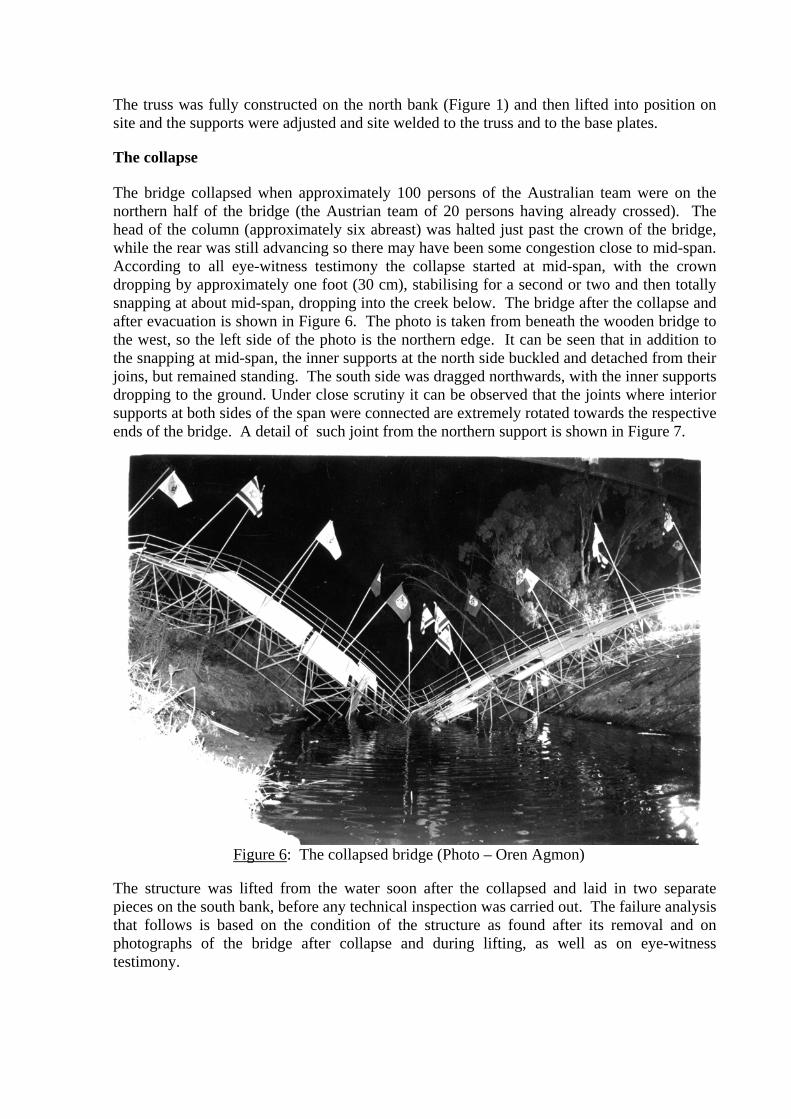
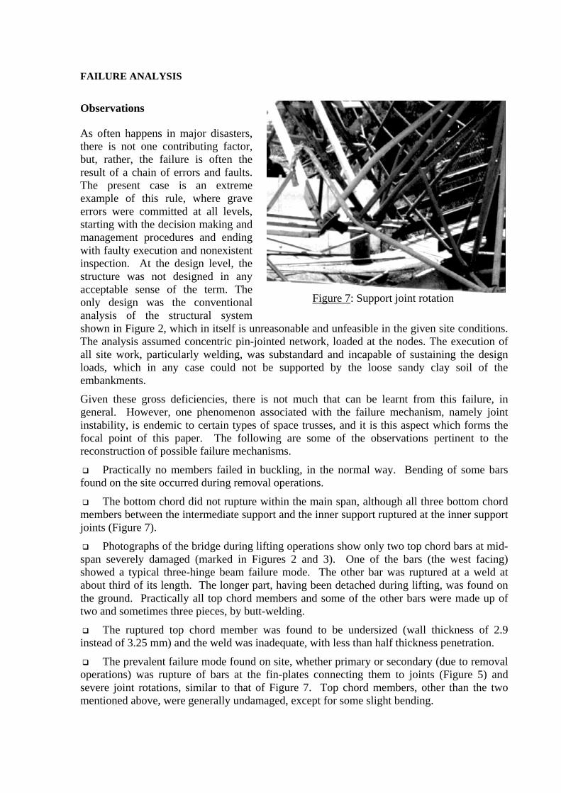
The bridge collapsed when approximately 100 persons of the Australian team were on the northern half of the bridge (the Austrian team of 20 persons having already crossed). The head of the column (approximately six abreast) was halted just past the crown of the bridge, while the rear was still advancing so there may have been some congestion close to mid-span. According to all eye-witness testimony the collapse started at mid-span, with the crown dropping by approximately one foot (30 cm), stabilising for a second or two and then totally snapping at about mid-span, dropping into the creek below. The bridge after the collapse and after evacuation is shown in Figure 6. The photo is taken from beneath the wooden bridge to the west, so the left side of the photo is the northern edge. It can be seen that in addition to the snapping at mid-span, the inner supports at the north side buckled and detached from their joins, but remained standing. The south side was dragged northwards, with the inner supports dropping to the ground. Under close scrutiny it can be observed that the joints where interior supports at both sides of the span were connected are extremely rotated towards the respective ends of the bridge. A detail of such joint from the northern support is shown in Figure 7.
The structure was lifted from the water soon after the collapsed and laid in two separate pieces on the south bank, before any technical inspection was carried out. The failure analysis that follows is based on the condition of the structure as found after its removal and on photographs of the bridge after collapse and during lifting, as well as on eye-witness testimony.
Figure 6: The collapsed bridge (Photo – Oren Agmon)
FAILURE ANALYSIS
Observations
As often happens in major disasters, there is not one contributing factor, but, rather, the failure is often the result of a chain of errors and faults. The present case is an extreme example of this rule, where grave errors were committed at all levels, starting with the decision making and management procedures and ending with faulty execution and nonexistent inspection. At the design level, the structure was not designed in any acceptable sense of the term. The only design was the conventional analysis of the structural system shown in Figure 2, which in itself is unreasonable and unfeasible in the given site conditions. The analysis assumed concentric pin-jointed network, loaded at the nodes. The execution of all site work, particularly welding, was substandard and incapable of sustaining the design loads, which in any case could not be supported by the loose sandy clay soil of the embankments.
Given these gross deficiencies, there is not much that can be learnt from this failure, in general. However, one phenomenon associated with the failure mechanism, namely joint instability, is endemic to certain types of space trusses, and it is this aspect which forms the focal point of this paper. The following are some of the observations pertinent to the reconstruction of possible failure mechanisms.
Practically no members failed in buckling, in the normal way. Bending of some bars found on the site occurred during removal operations.
The bottom chord did not rupture within the main span, although all three bottom chord members between the intermediate support and the inner support ruptured at the inner support joints (Figure 7).
Photographs of the bridge during lifting operations show only two top chord bars at mid-span severely damaged (marked in Figures 2 and 3). One of the bars (the west facing) showed a typical three-hinge beam failure mode. The other bar was ruptured at a weld at about third of its length. The longer part, having been detached during lifting, was found on the ground. Practically all top chord members and some of the other bars were made up of two and sometimes three pieces, by butt-welding.
The ruptured top chord member was found to be undersized (wall thickness of 2.9 instead of 3.25 mm) and the weld was inadequate, with less than half thickness penetration.
The prevalent failure mode found on site, whether primary or secondary (due to removal operations) was rupture of bars at the fin-plates connecting them to joints (Figure 5) and severe joint rotations, similar to that of Figure 7. Top chord members, other than the two mentioned above, were generally undamaged, except for some slight bending.
Figure 7: Support joint rotation
Welding of support columns both to base plates and to the truss joints was incomplete, of poor quality and incapable of supporting design loads. In many cases columns were placed eccentrically on base plates. Some of the base plates of interior supports were placed on a slope on the embankment, with hardly any levelling.
Failure mechanisms
Based on the above observations (and others, not presented here), failure could have initiated at two general locations – top chord at mid-span, or at the interior northern support – by one or a combination of the following mechanisms:
Rupture of the weld of the eastern mid-span top chord member due to flexure. This would lead to overstress of the companion top-chord member and its failure by a combination of flexure and joint rotation (see analysis below).
Failure of either central top chord members by joint instability followed by flexure.
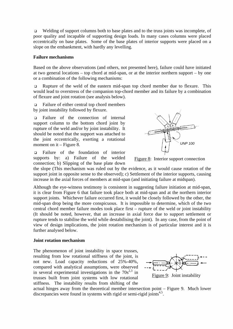
Failure of the connection of internal support column to the bottom chord joint by rupture of the weld and/or by joint instability. It should be noted that the support was attached to the joint eccentrically, exerting a rotational moment on it – Figure 8.
Failure of the foundation of interior supports by: a) Failure of the welded connection; b) Slipping of the base plate down the slope (This mechanism was ruled out by the evidence, as it would cause rotation of the support joint in opposite sense to the observed); c) Settlement of the interior supports, causing increase in the axial forces of members at mid-span (and initiating failure at midspan).
Although the eye-witness testimony is consistent in suggesting failure initiation at mid-span, it is clear from Figure 6 that failure took place both at mid-span and at the northern interior support joints. Whichever failure occurred first, it would be closely followed by the other, the mid-span drop being the more conspicuous. It is impossible to determine, which of the two central chord member failure modes took place first – rupture of the weld or joint instability (It should be noted, however, that an increase in axial force due to support settlement or rupture tends to stabilise the weld while destabilising the joint). In any case, from the point of view of design implications, the joint rotation mechanism is of particular interest and it is further analysed below.
Joint rotation mechanism
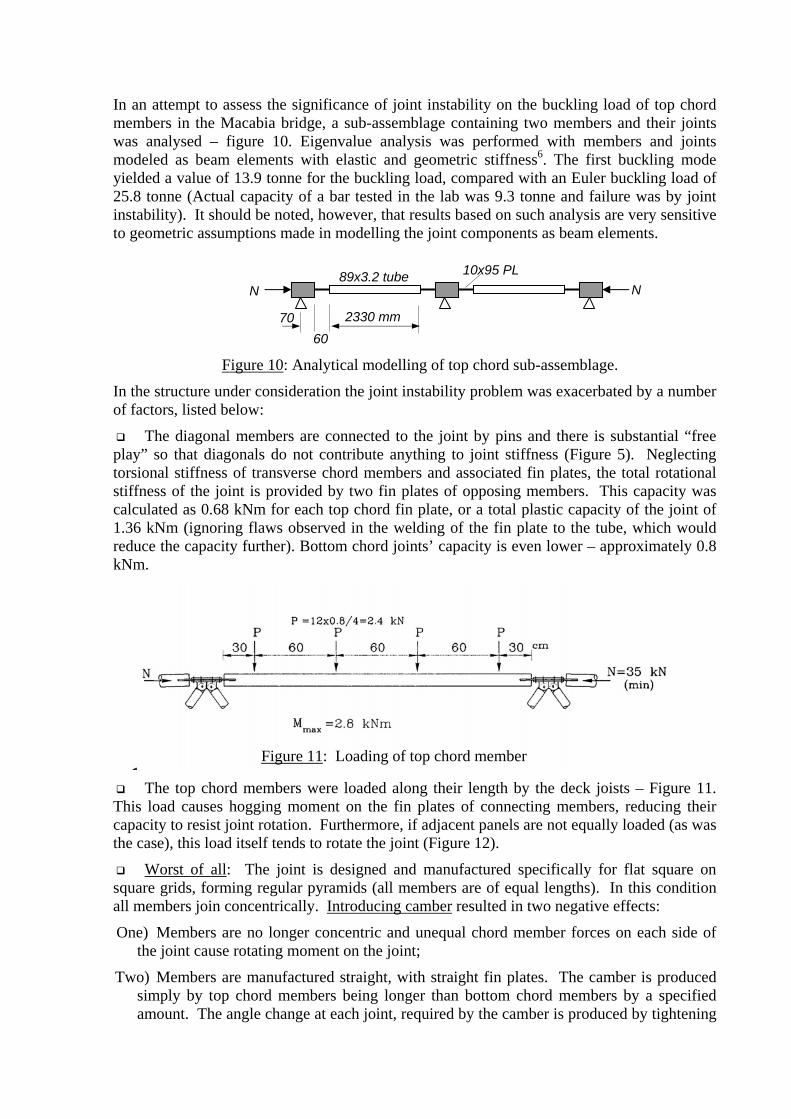
The phenomenon of joint instability in space trusses, resulting from low rotational stiffness of the joint, is not new. Load capacity reductions of 25%-40%, compared with analytical assumptions, were observed in several experimental investigations in the 70s2,3 in trusses built from joint systems with low rotational stiffness. The instability results from shifting of the actual hinges away from the theoretical member intersection point – Figure 9. Much lower discrepancies were found in systems with rigid or semi-rigid joints4,5.
Figure 8: Interior support connection
Figure 9: Joint instability
UNP 100
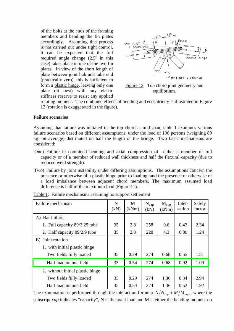
In an attempt to assess the significance of joint instability on the buckling load of top chord members in the Macabia bridge, a sub-assemblage containing two members and their joints was analysed – figure 10. Eigenvalue analysis was performed with members and joints modeled as beam elements with elastic and geometric stiffness6. The first buckling mode yielded a value of 13.9 tonne for the buckling load, compared with an Euler buckling load of 25.8 tonne (Actual capacity of a bar tested in the lab was 9.3 tonne and failure was by joint instability). It should be noted, however, that results based on such analysis are very sensitive to geometric assumptions made in modelling the joint components as beam elements.
In the structure under consideration the joint instability problem was exacerbated by a number of factors, listed below:
The diagonal members are connected to the joint by pins and there is substantial “free play” so that diagonals do not contribute anything to joint stiffness (Figure 5). Neglecting torsional stiffness of transverse chord members and associated fin plates, the total rotational stiffness of the joint is provided by two fin plates of opposing members. This capacity was calculated as 0.68 kNm for each top chord fin plate, or a total plastic capacity of the joint of 1.36 kNm (ignoring flaws observed in the welding of the fin plate to the tube, which would reduce the capacity further). Bottom chord joints’ capacity is even lower – approximately 0.8 kNm.
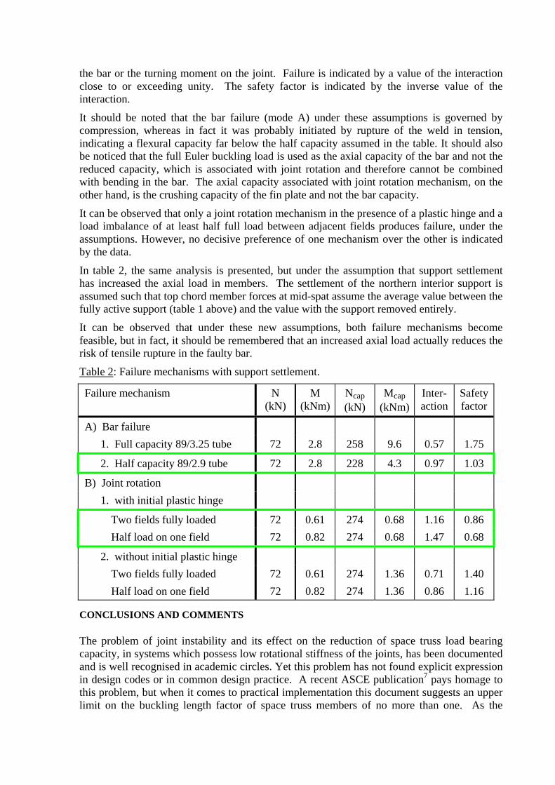
The top chord members were loaded along their length by the deck joists – Figure 11. This load causes hogging moment on the fin plates of connecting members, reducing their capacity to resist joint rotation. Furthermore, if adjacent panels are not equally loaded (as was the case), this load itself tends to rotate the joint (Figure 12).
Worst of all: The joint is designed and manufactured specifically for flat square on square grids, forming regular pyramids (all members are of equal lengths). In this condition all members join concentrically. Introducing camber resulted in two negative effects:
One) Members are no longer concentric and unequal chord member forces on each side of the joint cause rotating moment on the joint;
Two) Members are manufactured straight, with straight fin plates. The camber is produced simply by top chord members being longer than bottom chord members by a specified amount. The angle change at each joint, required by the camber is produced by tightening
Figure 10: Analytical modelling of top chord sub-assemblage.
N N
70 60
2330 mm
89x3.2 tube 10x95 PL
Figure 11: Loading of top chord member
of the bolts at the ends of the framing members and bending the fin plates accordingly. Assuming this process is not carried out under tight control, it can be expected that the full required angle change (2.5o in this case) takes place in one of the two fin plates. In view of the short length of plate between joint hub and tube end (practically zero), this is sufficient to form a plastic hinge, leaving only one plate (at best) with any elastic stiffness reserve to resist any applied rotating moment. The combined effects of bending and eccentricity is illustrated in Figure 12 (rotation is exaggerated in the figure).
Failure scenarios
Assuming that failure was initiated in the top chord at mid-span, table 1 examines various failure scenarios based on different assumptions, under the load of 100 persons (weighing 80 kg. on average) distributed on half the length of the bridge. Two basic mechanisms are considered:
One) Failure in combined bending and axial compression of either a member of full capacity or of a member of reduced wall thickness and half the flexural capacity (due to reduced weld strength).
Two) Failure by joint instability under differing assumptions. The assumptions concern the presence or otherwise of a plastic hinge prior to loading, and the presence or otherwise of a load imbalance between adjacent chord members. The maximum assumed load difference is half of the maximum load (Figure 11).
Table 1: Failure mechanisms assuming no support settlement
Failure mechanism N (kN)
M (kNm)
Ncap (kN)
Mcap (kNm)
Inter- action
Safetyfactor
A) Bar failure 1. Full capacity 89/3.25 tube 35 2.8 258 9.6 0.43 2.34 2. Half capacity 89/2.9 tube 35 2.8 228 4.3 0.80 1.24
B) Joint rotation 1. with initial plastic hinge
Two fields fully loaded 35 0.29 274 0.68 0.55 1.81
Half load on one field 35 0.54 274 0.68 0.92 1.09
2. without initial plastic hinge Two fields fully loaded 35 0.29 274 1.36 0.34 2.94 Half load on one field 35 0.54 274 1.36 0.52 1.92
The examination is performed through the interaction formula capcap MMNN + , where the subscript cap indicates “capacity”, N is the axial load and M is either the bending moment on
Figure 12: Top chord joint geometry and equilibrium.
the bar or the turning moment on the joint. Failure is indicated by a value of the interaction close to or exceeding unity. The safety factor is indicated by the inverse value of the interaction.
It should be noted that the bar failure (mode A) under these assumptions is governed by compression, whereas in fact it was probably initiated by rupture of the weld in tension, indicating a flexural capacity far below the half capacity assumed in the table. It should also be noticed that the full Euler buckling load is used as the axial capacity of the bar and not the reduced capacity, which is associated with joint rotation and therefore cannot be combined with bending in the bar. The axial capacity associated with joint rotation mechanism, on the other hand, is the crushing capacity of the fin plate and not the bar capacity.
It can be observed that only a joint rotation mechanism in the presence of a plastic hinge and a load imbalance of at least half full load between adjacent fields produces failure, under the assumptions. However, no decisive preference of one mechanism over the other is indicated by the data.
In table 2, the same analysis is presented, but under the assumption that support settlement has increased the axial load in members. The settlement of the northern interior support is assumed such that top chord member forces at mid-spat assume the average value between the fully active support (table 1 above) and the value with the support removed entirely.
It can be observed that under these new assumptions, both failure mechanisms become feasible, but in fact, it should be remembered that an increased axial load actually reduces the risk of tensile rupture in the faulty bar.
Table 2: Failure mechanisms with support settlement.
Failure mechanism N (kN)
M (kNm)
Ncap (kN)
Mcap (kNm)
Inter- action
Safetyfactor
A) Bar failure 1. Full capacity 89/3.25 tube 72 2.8 258 9.6 0.57 1.75
2. Half capacity 89/2.9 tube 72 2.8 228 4.3 0.97 1.03
B) Joint rotation 1. with initial plastic hinge
Two fields fully loaded 72 0.61 274 0.68 1.16 0.86 Half load on one field 72 0.82 274 0.68 1.47 0.68
2. without initial plastic hinge Two fields fully loaded 72 0.61 274 1.36 0.71 1.40 Half load on one field 72 0.82 274 1.36 0.86 1.16
CONCLUSIONS AND COMMENTS
The problem of joint instability and its effect on the reduction of space truss load bearing capacity, in systems which possess low rotational stiffness of the joints, has been documented and is well recognised in academic circles. Yet this problem has not found explicit expression in design codes or in common design practice. A recent ASCE publication7 pays homage to this problem, but when it comes to practical implementation this document suggests an upper limit on the buckling length factor of space truss members of no more than one. As the
simple analytical model presented above (Figure 10) indicates, joint rotation can result in substantially higher buckling lengths (a factor of approximately 1.3 in the above example). The ASCE approach thus represents an unsafe design in many cases.
The structural failure of the Macabia bridge is the first reported major collapse in which joint instability featured prominently. There is no direct evidence to suggest that joint instability was, in fact, the mechanism triggering the collapse, as there existed several serious design and construction faults, each of which could have independently caused the collapse. However, once failure was initiated by whatever mechanism at whatever location, joint instability took place at all failure localities, namely at the mid-span top chord joints and at the interior support joints.
In this particular case, the risk of joint instability was amplified by a seemingly minor variation – the introduction of camber into a system specifically designed for planar surfaces. The dire consequences which sometimes accompany simple alterations or seemingly unimportant details are encountered in many historical structural failures (for instance the walkway collapse at the Hyatt Regency hotel in Kansas City in 1981). This is any engineer’s nightmare, and it serves to highlight the importance of attention to detail, which is the hallmark of true professionalism. It can be said that the root causes of any accident can be traced back to a lack of professionalism, and this is certainly the case in the Macabia bridge disaster.
Perhaps the most important lesson to be learnt from this disaster, other than the need to incorporate joint instability and stiffness considerations in standard design practice, is the more general necessity to verify the conformation of analytical models to actual structural behaviour. Clearly, the analytical modelling of trusses as pin-jointed bar networks is inappropriate for a large class of structures which are routinely thus modelled. This general principle is particularly relevant as we become more and more dependent on computer analysis and design and the borderline between reality and virtual reality become more and more obscure.
REFERENCES
1. Hanaor, A., Special Issue on Prefabricated Spatial Frame Systems, International Journal of Space Structures, V 10, N 3, 1995.
2. Schmidt, L.C., Morgan, P.R. and Hanaor, A., Ultimate Load Testing of Space Trusses, Journal of the Structural Division, ASCE, V 102, N ST7, 1982.
3. Hanaor, A., Snags and Solutions in Double-layer Grid Design, Building Structures, Proc. Structures congress ’87, Sherman, D.R., ed., ASCE, New York, 1987, 319-331.
4. Collins, I.M., An Investigation into the collapse Behavior of Double-layer Grids, Third International Conference on Space Structures, Proc., Nooshin, H., ed., Elsevier Applied Science, Barking, 1984, 400-405.
5. Hanaor, A,, Marsh, C. and Parke, G.A.R., Modification of the Behavior of double-Layer Grids: Overview, Journal of Structural Engineering, ASCE, V 115, N 5, 1989, 1021-1037.
6. Sheinman, Y., in Report of the subcommittee of the committee of enquiry of the bridge collapse at the opening of the Macabia, 14 July 1997, Appendix D of the report of the committee of enquiry, National Building Research Institute, The Technion, Israel Institute of Technolgy, 1997.
7. ASCE Task Committee on Double-Layer Grids, Cuoco, D.A., ed., Guidelines for the Design of Double-Layer Grids, ASCE, New York, 1997.