Embed Size (px)
Citation preview
Lessons Learned Analyzing Transmission Faults
David Costello Schweitzer Engineering Laboratories, Inc.
Published in the SEL Journal of Reliable Power, Volume 1, Number 1, July 2010
Previously presented at the 44th Annual Minnesota Power Systems Conference, November 2008,
62nd Annual Georgia Tech Protective Relaying Conference, May 2008, and 61st Annual Conference for Protective Relay Engineers, April 2008
Originally presented at the 34th Annual Western Protective Relay Conference, October 2007
1
Lessons Learned Analyzing Transmission Faults David Costello, Schweitzer Engineering Laboratories, Inc.
Abstract—Transmission line relays record interesting power system phenomena and misoperations due to a variety of problems. By analyzing event records, some common setting mistakes and misapplications have become evident. Setting and testing recommendations can be made to avoid these problems. In the interest of reducing transmission line relay misoperations, this technical paper shares practical lessons learned through experience analyzing transmission line relay event reports.
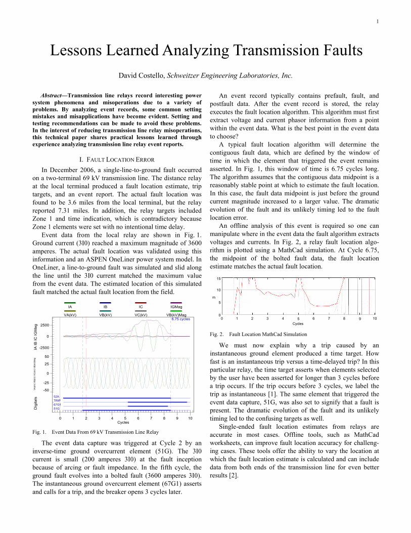
I. FAULT LOCATION ERROR In December 2006, a single-line-to-ground fault occurred
on a two-terminal 69 kV transmission line. The distance relay at the local terminal produced a fault location estimate, trip targets, and an event report. The actual fault location was found to be 3.6 miles from the local terminal, but the relay reported 7.31 miles. In addition, the relay targets included Zone 1 and time indication, which is contradictory because Zone 1 elements were set with no intentional time delay.
Event data from the local relay are shown in Fig. 1. Ground current (3I0) reached a maximum magnitude of 3600 amperes. The actual fault location was validated using this information and an ASPEN OneLiner power system model. In OneLiner, a line-to-ground fault was simulated and slid along the line until the 3I0 current matched the maximum value from the event data. The estimated location of this simulated fault matched the actual fault location from the field.
51G67G1TRIP52A
-2500
0
2500
-50
-25
0
25
50
0 1 2 3 4 5 6 7 8 9 10
6.75 cycles
IA IB
IC IG
Mag
VA(k
V) V
B(kV
) VC
(kV)
VB(
kV)M
agD
igita
ls
Cycles
IA IB IC IGMag
VA(kV) VB(kV) VC(kV) VB(kV)Mag
Fig. 1. Event Data From 69 kV Transmission Line Relay
The event data capture was triggered at Cycle 2 by an inverse-time ground overcurrent element (51G). The 3I0 current is small (200 amperes 3I0) at the fault inception because of arcing or fault impedance. In the fifth cycle, the ground fault evolves into a bolted fault (3600 amperes 3I0). The instantaneous ground overcurrent element (67G1) asserts and calls for a trip, and the breaker opens 3 cycles later.
An event record typically contains prefault, fault, and postfault data. After the event record is stored, the relay executes the fault location algorithm. This algorithm must first extract voltage and current phasor information from a point within the event data. What is the best point in the event data to choose?
A typical fault location algorithm will determine the contiguous fault data, which are defined by the window of time in which the element that triggered the event remains asserted. In Fig. 1, this window of time is 6.75 cycles long. The algorithm assumes that the contiguous data midpoint is a reasonably stable point at which to estimate the fault location. In this case, the fault data midpoint is just before the ground current magnitude increased to a larger value. The dramatic evolution of the fault and its unlikely timing led to the fault location error.
An offline analysis of this event is required so one can manipulate where in the event data the fault algorithm extracts voltages and currents. In Fig. 2, a relay fault location algo-rithm is plotted using a MathCad simulation. At Cycle 6.75, the midpoint of the bolted fault data, the fault location estimate matches the actual fault location.
0 1 2 3 4 6 7 8 10Cycles
m
10
0
5
15
5 9
Fig. 2. Fault Location MathCad Simulation
We must now explain why a trip caused by an instantaneous ground element produced a time target. How fast is an instantaneous trip versus a time-delayed trip? In this particular relay, the time target asserts when elements selected by the user have been asserted for longer than 3 cycles before a trip occurs. If the trip occurs before 3 cycles, we label the trip as instantaneous [1]. The same element that triggered the event data capture, 51G, was also set to signify that a fault is present. The dramatic evolution of the fault and its unlikely timing led to the confusing targets as well.
Single-ended fault location estimates from relays are accurate in most cases. Offline tools, such as MathCad worksheets, can improve fault location accuracy for challeng-ing cases. These tools offer the ability to vary the location at which the fault location estimate is calculated and can include data from both ends of the transmission line for even better results [2].
2
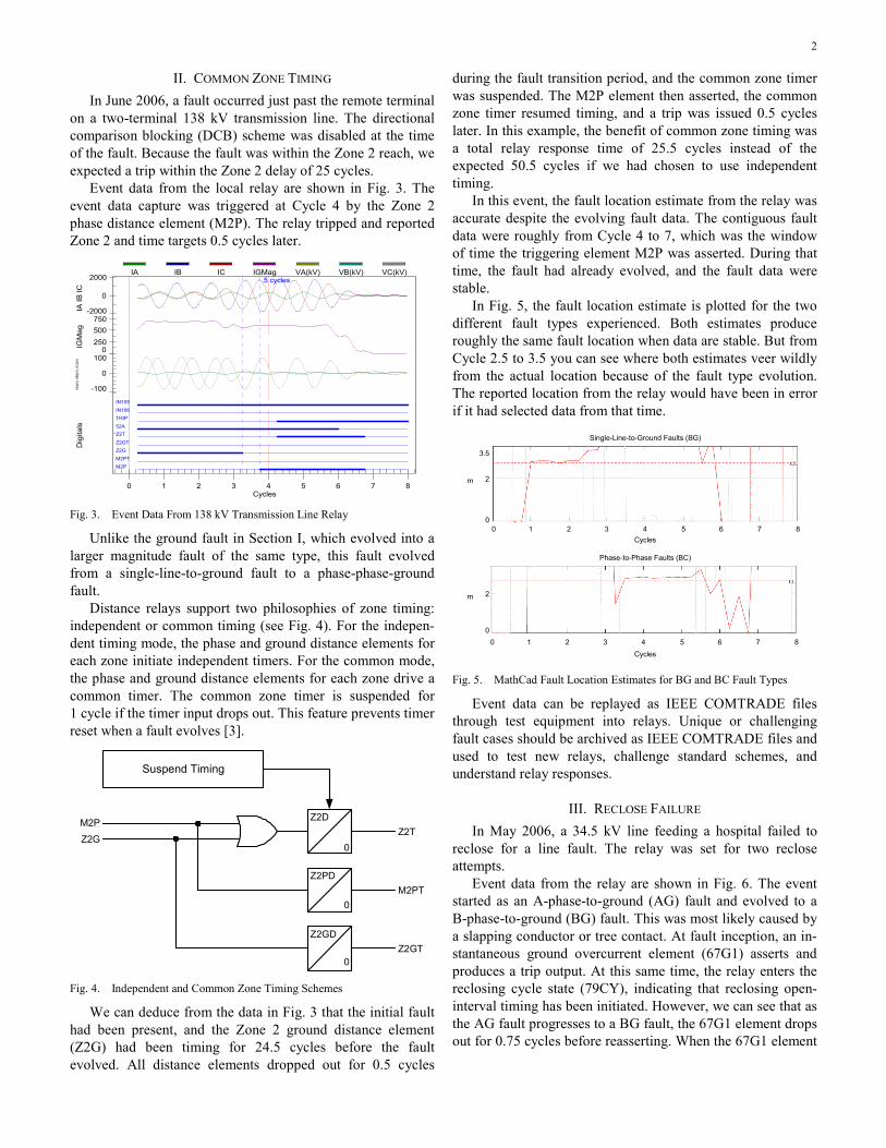
II. COMMON ZONE TIMING In June 2006, a fault occurred just past the remote terminal
on a two-terminal 138 kV transmission line. The directional comparison blocking (DCB) scheme was disabled at the time of the fault. Because the fault was within the Zone 2 reach, we expected a trip within the Zone 2 delay of 25 cycles.
Event data from the local relay are shown in Fig. 3. The event data capture was triggered at Cycle 4 by the Zone 2 phase distance element (M2P). The relay tripped and reported Zone 2 and time targets 0.5 cycles later.
M2PM2PTZ2GZ2GTZ2T52ATRIPIN106IN105
-2000
0
2000
0250500750
-100
0
100
0 1 2 3 4 5 6 7 8
.5 cycles
IA IB
ICIG
Mag
VA(k
V) V
B(kV
) VC
(kV)
Dig
itals
Cycles
IA IB IC IGMag VA(kV) VB(kV) VC(kV)
Fig. 3. Event Data From 138 kV Transmission Line Relay
Unlike the ground fault in Section I, which evolved into a larger magnitude fault of the same type, this fault evolved from a single-line-to-ground fault to a phase-phase-ground fault.
Distance relays support two philosophies of zone timing: independent or common timing (see Fig. 4). For the indepen-dent timing mode, the phase and ground distance elements for each zone initiate independent timers. For the common mode, the phase and ground distance elements for each zone drive a common timer. The common zone timer is suspended for 1 cycle if the timer input drops out. This feature prevents timer reset when a fault evolves [3].
Suspend Timing
Z2D
0
Z2PD
Z2GD
0
0
Z2T
M2PT
Z2GT
M2P
Z2G
Fig. 4. Independent and Common Zone Timing Schemes
We can deduce from the data in Fig. 3 that the initial fault had been present, and the Zone 2 ground distance element (Z2G) had been timing for 24.5 cycles before the fault evolved. All distance elements dropped out for 0.5 cycles
during the fault transition period, and the common zone timer was suspended. The M2P element then asserted, the common zone timer resumed timing, and a trip was issued 0.5 cycles later. In this example, the benefit of common zone timing was a total relay response time of 25.5 cycles instead of the expected 50.5 cycles if we had chosen to use independent timing.
In this event, the fault location estimate from the relay was accurate despite the evolving fault data. The contiguous fault data were roughly from Cycle 4 to 7, which was the window of time the triggering element M2P was asserted. During that time, the fault had already evolved, and the fault data were stable.
In Fig. 5, the fault location estimate is plotted for the two different fault types experienced. Both estimates produce roughly the same fault location when data are stable. But from Cycle 2.5 to 3.5 you can see where both estimates veer wildly from the actual location because of the fault type evolution. The reported location from the relay would have been in error if it had selected data from that time.
Single-Line-to-Ground Faults (BG)
3.5
0 1 2 3 4 5 6 7 80
0 1 2 3 4 5 6 7 80
2
Phase-to-Phase Faults (BC)
2
Cycles
Cycles
m
m
Fig. 5. MathCad Fault Location Estimates for BG and BC Fault Types
Event data can be replayed as IEEE COMTRADE files through test equipment into relays. Unique or challenging fault cases should be archived as IEEE COMTRADE files and used to test new relays, challenge standard schemes, and understand relay responses.
III. RECLOSE FAILURE In May 2006, a 34.5 kV line feeding a hospital failed to
reclose for a line fault. The relay was set for two reclose attempts.
Event data from the relay are shown in Fig. 6. The event started as an A-phase-to-ground (AG) fault and evolved to a B-phase-to-ground (BG) fault. This was most likely caused by a slapping conductor or tree contact. At fault inception, an in-stantaneous ground overcurrent element (67G1) asserts and produces a trip output. At this same time, the relay enters the reclosing cycle state (79CY), indicating that reclosing open-interval timing has been initiated. However, we can see that as the AG fault progresses to a BG fault, the 67G1 element drops out for 0.75 cycles before reasserting. When the 67G1 element
3
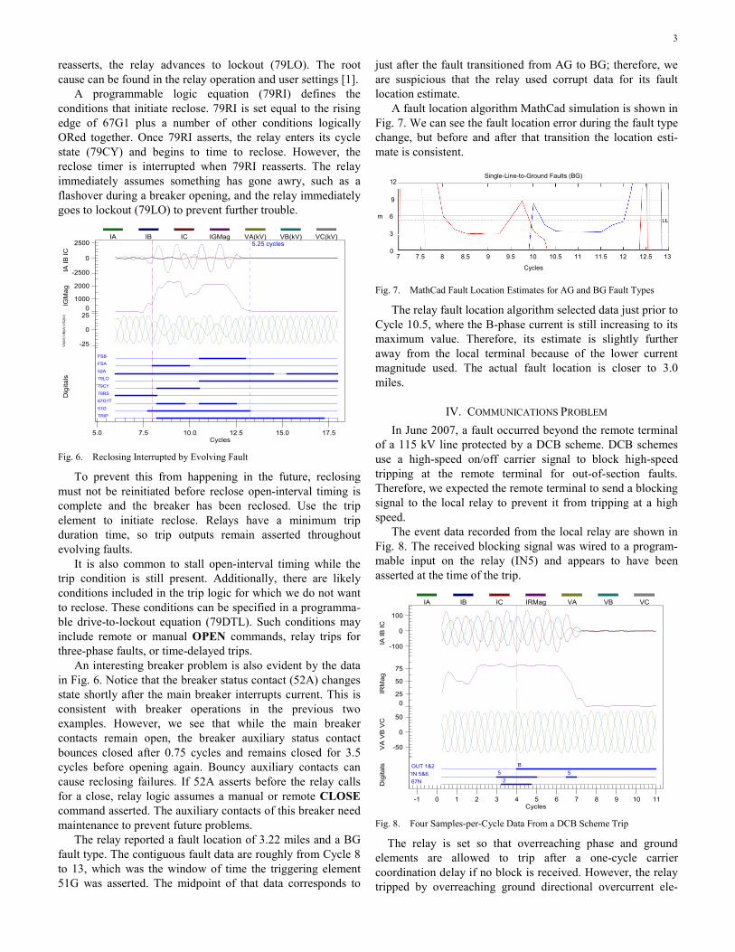
reasserts, the relay advances to lockout (79LO). The root cause can be found in the relay operation and user settings [1].
A programmable logic equation (79RI) defines the conditions that initiate reclose. 79RI is set equal to the rising edge of 67G1 plus a number of other conditions logically ORed together. Once 79RI asserts, the relay enters its cycle state (79CY) and begins to time to reclose. However, the reclose timer is interrupted when 79RI reasserts. The relay immediately assumes something has gone awry, such as a flashover during a breaker opening, and the relay immediately goes to lockout (79LO) to prevent further trouble.
TRIP
51G
67G1T
79RS
79CY
79LO
52A
FSA
FSB
-2500
0
2500
01000
2000
-25
0
25
5.0 7.5 10.0 12.5 15.0 17.5
5.25 cycles
IA IB
ICIG
Mag
VA(k
V) V
B(kV
) VC
(kV)
Dig
itals
Cycles
IA IB IC IGMag VA(kV) VB(kV) VC(kV)
Fig. 6. Reclosing Interrupted by Evolving Fault
To prevent this from happening in the future, reclosing must not be reinitiated before reclose open-interval timing is complete and the breaker has been reclosed. Use the trip element to initiate reclose. Relays have a minimum trip duration time, so trip outputs remain asserted throughout evolving faults.
It is also common to stall open-interval timing while the trip condition is still present. Additionally, there are likely conditions included in the trip logic for which we do not want to reclose. These conditions can be specified in a programma-ble drive-to-lockout equation (79DTL). Such conditions may include remote or manual OPEN commands, relay trips for three-phase faults, or time-delayed trips.
An interesting breaker problem is also evident by the data in Fig. 6. Notice that the breaker status contact (52A) changes state shortly after the main breaker interrupts current. This is consistent with breaker operations in the previous two examples. However, we see that while the main breaker contacts remain open, the breaker auxiliary status contact bounces closed after 0.75 cycles and remains closed for 3.5 cycles before opening again. Bouncy auxiliary contacts can cause reclosing failures. If 52A asserts before the relay calls for a close, relay logic assumes a manual or remote CLOSE command asserted. The auxiliary contacts of this breaker need maintenance to prevent future problems.
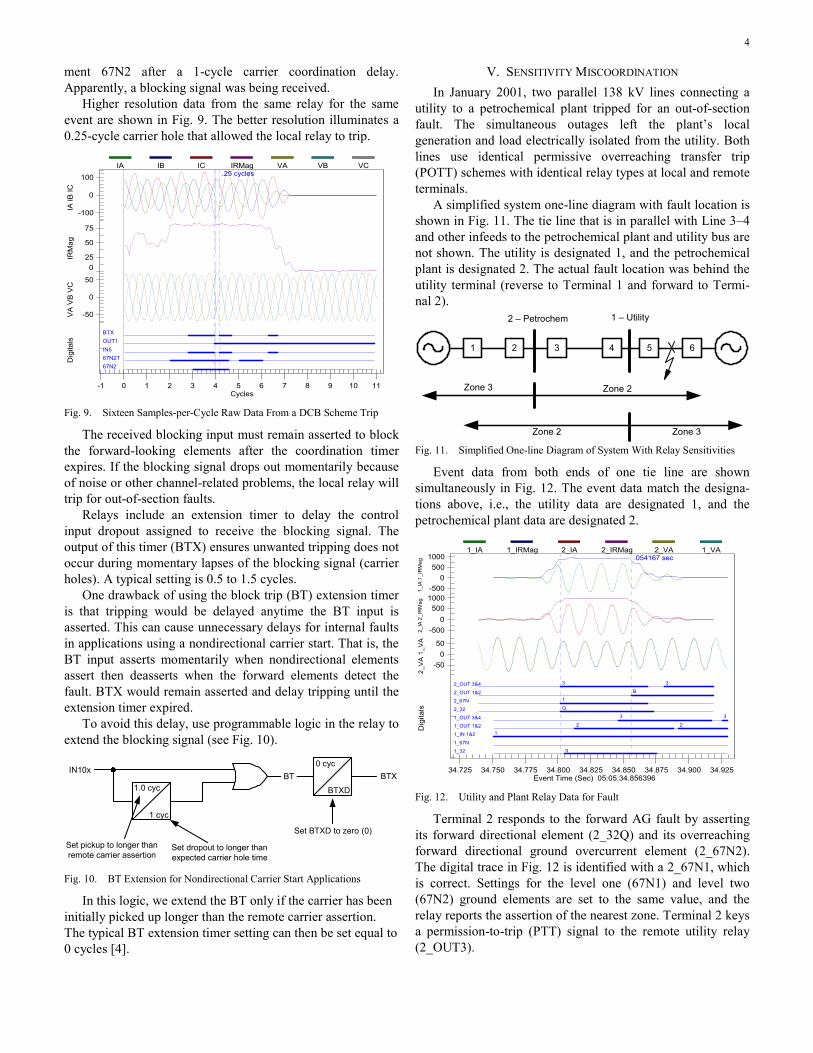
The relay reported a fault location of 3.22 miles and a BG fault type. The contiguous fault data are roughly from Cycle 8 to 13, which was the window of time the triggering element 51G was asserted. The midpoint of that data corresponds to
just after the fault transitioned from AG to BG; therefore, we are suspicious that the relay used corrupt data for its fault location estimate.
A fault location algorithm MathCad simulation is shown in Fig. 7. We can see the fault location error during the fault type change, but before and after that transition the location esti-mate is consistent.
Single-Line-to-Ground Faults (BG)12
7 7.5 8.5 9.5 10 11 11.5 12.5 13
3
9
Cycles
6
08 9 10.5 12
m
Fig. 7. MathCad Fault Location Estimates for AG and BG Fault Types
The relay fault location algorithm selected data just prior to Cycle 10.5, where the B-phase current is still increasing to its maximum value. Therefore, its estimate is slightly further away from the local terminal because of the lower current magnitude used. The actual fault location is closer to 3.0 miles.
IV. COMMUNICATIONS PROBLEM In June 2007, a fault occurred beyond the remote terminal
of a 115 kV line protected by a DCB scheme. DCB schemes use a high-speed on/off carrier signal to block high-speed tripping at the remote terminal for out-of-section faults. Therefore, we expected the remote terminal to send a blocking signal to the local relay to prevent it from tripping at a high speed.
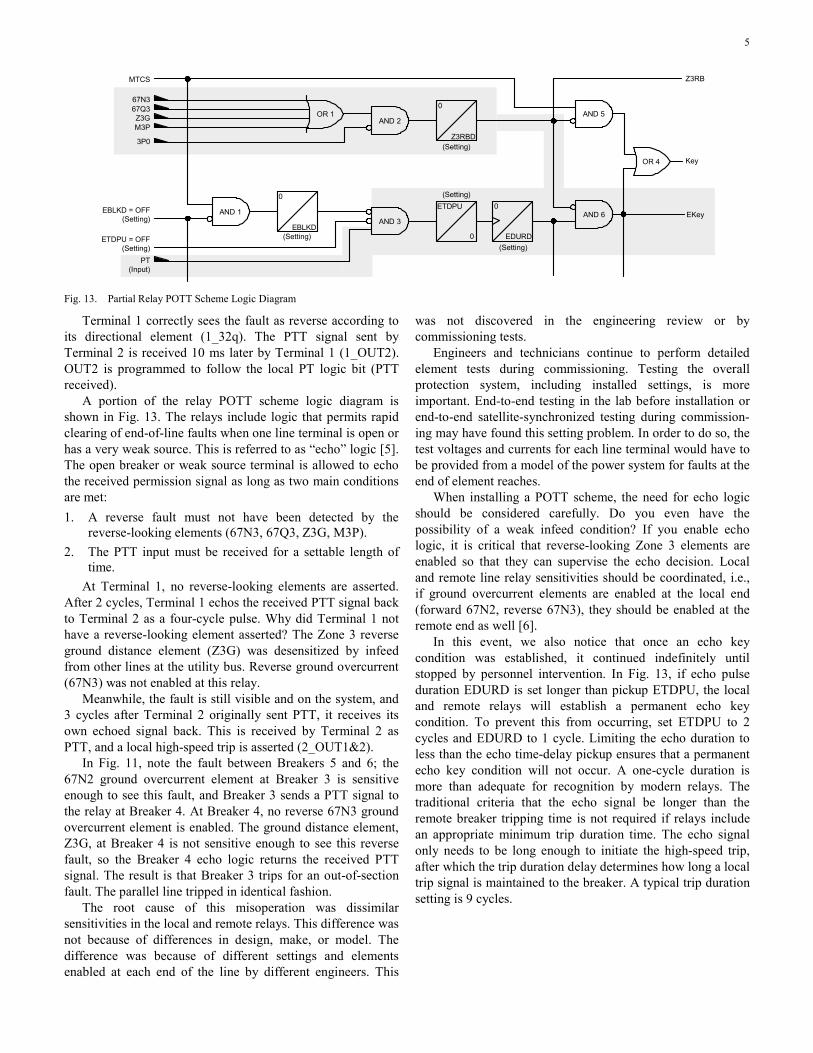
The event data recorded from the local relay are shown in Fig. 8. The received blocking signal was wired to a program-mable input on the relay (IN5) and appears to have been asserted at the time of the trip.
67N 2IN 5&6 5 5OUT 1&2 B
-100
0
100
025
50
75
-50
0
50
-1 0 1 2 3 4 5 6 7 8 9 10 11
IA IB
ICIR
Mag
VA
VB
VC
Dig
itals
Cycles
IA IB IC IRMag VA VB VC
Fig. 8. Four Samples-per-Cycle Data From a DCB Scheme Trip
The relay is set so that overreaching phase and ground elements are allowed to trip after a one-cycle carrier coordination delay if no block is received. However, the relay tripped by overreaching ground directional overcurrent ele-
4
ment 67N2 after a 1-cycle carrier coordination delay. Apparently, a blocking signal was being received.
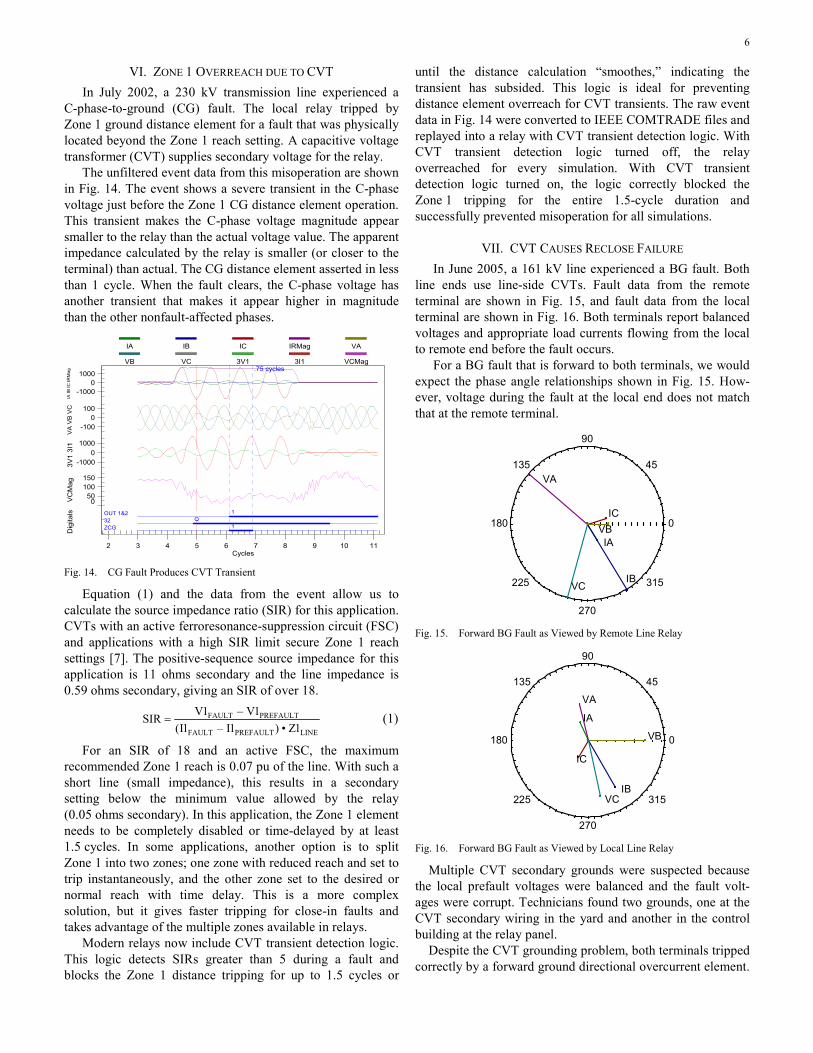
Higher resolution data from the same relay for the same event are shown in Fig. 9. The better resolution illuminates a 0.25-cycle carrier hole that allowed the local relay to trip.
67N267N2TIN5OUT1BTX
-100
0
100
025
50
75
-50
0
50
-1 0 1 2 3 4 5 6 7 8 9 10 11
.25 cycles
IA IB
ICIR
Mag
VA
VB
VC
Dig
itals
Cycles
IA IB IC IRMag VA VB VC
Fig. 9. Sixteen Samples-per-Cycle Raw Data From a DCB Scheme Trip
The received blocking input must remain asserted to block the forward-looking elements after the coordination timer expires. If the blocking signal drops out momentarily because of noise or other channel-related problems, the local relay will trip for out-of-section faults.
Relays include an extension timer to delay the control input dropout assigned to receive the blocking signal. The output of this timer (BTX) ensures unwanted tripping does not occur during momentary lapses of the blocking signal (carrier holes). A typical setting is 0.5 to 1.5 cycles.
One drawback of using the block trip (BT) extension timer is that tripping would be delayed anytime the BT input is asserted. This can cause unnecessary delays for internal faults in applications using a nondirectional carrier start. That is, the BT input asserts momentarily when nondirectional elements assert then deasserts when the forward elements detect the fault. BTX would remain asserted and delay tripping until the extension timer expired.
To avoid this delay, use programmable logic in the relay to extend the blocking signal (see Fig. 10).
BT BTX0 cyc
BTXD1.0 cyc
1 cyc
IN10x
Set pickup to longer than remote carrier assertion
Set dropout to longer than expected carrier hole time
Set BTXD to zero (0)
Fig. 10. BT Extension for Nondirectional Carrier Start Applications
In this logic, we extend the BT only if the carrier has been initially picked up longer than the remote carrier assertion. The typical BT extension timer setting can then be set equal to 0 cycles [4].
V. SENSITIVITY MISCOORDINATION In January 2001, two parallel 138 kV lines connecting a
utility to a petrochemical plant tripped for an out-of-section fault. The simultaneous outages left the plant’s local generation and load electrically isolated from the utility. Both lines use identical permissive overreaching transfer trip (POTT) schemes with identical relay types at local and remote terminals.
A simplified system one-line diagram with fault location is shown in Fig. 11. The tie line that is in parallel with Line 3–4 and other infeeds to the petrochemical plant and utility bus are not shown. The utility is designated 1, and the petrochemical plant is designated 2. The actual fault location was behind the utility terminal (reverse to Terminal 1 and forward to Termi-nal 2).
1 2 3 5 64
Zone 3 Zone 2
Zone 2 Zone 3
2 – Petrochem 1 – Utility
Fig. 11. Simplified One-line Diagram of System With Relay Sensitivities
Event data from both ends of one tie line are shown simultaneously in Fig. 12. The event data match the designa-tions above, i.e., the utility data are designated 1, and the petrochemical plant data are designated 2.
1_32 q1_67N
1_IN 1&2 11_OUT 1&2 2 21_OUT 3&4 3 32_32 Q2_67N 12_OUT 1&2 B2_OUT 3&4 3 3
-5000
5001000
-5000
5001000
-500
50
34.725 34.750 34.775 34.800 34.825 34.850 34.875 34.900 34.925
.054167 sec
1_IA
1_I
RM
ag2_
IA 2
_IR
Mag
2_V
A 1
_VA
Dig
itals
Event Time (Sec) 05:05:34.856396
1_IA 1_IRMag 2_IA 2_IRMag 2_VA 1_VA
Fig. 12. Utility and Plant Relay Data for Fault
Terminal 2 responds to the forward AG fault by asserting its forward directional element (2_32Q) and its overreaching forward directional ground overcurrent element (2_67N2). The digital trace in Fig. 12 is identified with a 2_67N1, which is correct. Settings for the level one (67N1) and level two (67N2) ground elements are set to the same value, and the relay reports the assertion of the nearest zone. Terminal 2 keys a permission-to-trip (PTT) signal to the remote utility relay (2_OUT3).
5
OR 4 Key
EKey
Z3RB
0
EDURD
ETDPU
0(Setting)
(Setting)
Z3RBD
0
(Setting)
AND 2
AND 3EBLKD
0
(Setting)
OR 1
AND 1
AND 5
AND 6
MTCS
67N367Q3Z3GM3P
3P0
EBLKD = OFF(Setting)
ETDPU = OFF(Setting)
PT(Input)
Fig. 13. Partial Relay POTT Scheme Logic Diagram
Terminal 1 correctly sees the fault as reverse according to its directional element (1_32q). The PTT signal sent by Terminal 2 is received 10 ms later by Terminal 1 (1_OUT2). OUT2 is programmed to follow the local PT logic bit (PTT received).
A portion of the relay POTT scheme logic diagram is shown in Fig. 13. The relays include logic that permits rapid clearing of end-of-line faults when one line terminal is open or has a very weak source. This is referred to as “echo” logic [5]. The open breaker or weak source terminal is allowed to echo the received permission signal as long as two main conditions are met: 1. A reverse fault must not have been detected by the
reverse-looking elements (67N3, 67Q3, Z3G, M3P). 2. The PTT input must be received for a settable length of
time. At Terminal 1, no reverse-looking elements are asserted.
After 2 cycles, Terminal 1 echos the received PTT signal back to Terminal 2 as a four-cycle pulse. Why did Terminal 1 not have a reverse-looking element asserted? The Zone 3 reverse ground distance element (Z3G) was desensitized by infeed from other lines at the utility bus. Reverse ground overcurrent (67N3) was not enabled at this relay.
Meanwhile, the fault is still visible and on the system, and 3 cycles after Terminal 2 originally sent PTT, it receives its own echoed signal back. This is received by Terminal 2 as PTT, and a local high-speed trip is asserted (2_OUT1&2).
In Fig. 11, note the fault between Breakers 5 and 6; the 67N2 ground overcurrent element at Breaker 3 is sensitive enough to see this fault, and Breaker 3 sends a PTT signal to the relay at Breaker 4. At Breaker 4, no reverse 67N3 ground overcurrent element is enabled. The ground distance element, Z3G, at Breaker 4 is not sensitive enough to see this reverse fault, so the Breaker 4 echo logic returns the received PTT signal. The result is that Breaker 3 trips for an out-of-section fault. The parallel line tripped in identical fashion.
The root cause of this misoperation was dissimilar sensitivities in the local and remote relays. This difference was not because of differences in design, make, or model. The difference was because of different settings and elements enabled at each end of the line by different engineers. This
was not discovered in the engineering review or by commissioning tests.
Engineers and technicians continue to perform detailed element tests during commissioning. Testing the overall protection system, including installed settings, is more important. End-to-end testing in the lab before installation or end-to-end satellite-synchronized testing during commission-ing may have found this setting problem. In order to do so, the test voltages and currents for each line terminal would have to be provided from a model of the power system for faults at the end of element reaches.
When installing a POTT scheme, the need for echo logic should be considered carefully. Do you even have the possibility of a weak infeed condition? If you enable echo logic, it is critical that reverse-looking Zone 3 elements are enabled so that they can supervise the echo decision. Local and remote line relay sensitivities should be coordinated, i.e., if ground overcurrent elements are enabled at the local end (forward 67N2, reverse 67N3), they should be enabled at the remote end as well [6].
In this event, we also notice that once an echo key condition was established, it continued indefinitely until stopped by personnel intervention. In Fig. 13, if echo pulse duration EDURD is set longer than pickup ETDPU, the local and remote relays will establish a permanent echo key condition. To prevent this from occurring, set ETDPU to 2 cycles and EDURD to 1 cycle. Limiting the echo duration to less than the echo time-delay pickup ensures that a permanent echo key condition will not occur. A one-cycle duration is more than adequate for recognition by modern relays. The traditional criteria that the echo signal be longer than the remote breaker tripping time is not required if relays include an appropriate minimum trip duration time. The echo signal only needs to be long enough to initiate the high-speed trip, after which the trip duration delay determines how long a local trip signal is maintained to the breaker. A typical trip duration setting is 9 cycles.
6
VI. ZONE 1 OVERREACH DUE TO CVT In July 2002, a 230 kV transmission line experienced a
C-phase-to-ground (CG) fault. The local relay tripped by Zone 1 ground distance element for a fault that was physically located beyond the Zone 1 reach setting. A capacitive voltage transformer (CVT) supplies secondary voltage for the relay.
The unfiltered event data from this misoperation are shown in Fig. 14. The event shows a severe transient in the C-phase voltage just before the Zone 1 CG distance element operation. This transient makes the C-phase voltage magnitude appear smaller to the relay than the actual voltage value. The apparent impedance calculated by the relay is smaller (or closer to the terminal) than actual. The CG distance element asserted in less than 1 cycle. When the fault clears, the C-phase voltage has another transient that makes it appear higher in magnitude than the other nonfault-affected phases.
ZCG 132 QOUT 1&2 1 .
-10000
1000
-1000
100
-10000
1000
050
100150
2 3 4 5 6 7 8 9 10 11
.75 cycles
IA IB
IC IR
Mag
VA
VB
VC
3V1
3I1
VC
Mag
Dig
itals
Cycles
IA IB IC IRMag VA
VB VC 3V1 3I1 VCMag
Fig. 14. CG Fault Produces CVT Transient
Equation (1) and the data from the event allow us to calculate the source impedance ratio (SIR) for this application. CVTs with an active ferroresonance-suppression circuit (FSC) and applications with a high SIR limit secure Zone 1 reach settings [7]. The positive-sequence source impedance for this application is 11 ohms secondary and the line impedance is 0.59 ohms secondary, giving an SIR of over 18.
LINEPREFAULTFAULT
PREFAULTFAULT
1Z•)1I–1I(1V–1VSIR = (1)
For an SIR of 18 and an active FSC, the maximum recommended Zone 1 reach is 0.07 pu of the line. With such a short line (small impedance), this results in a secondary setting below the minimum value allowed by the relay (0.05 ohms secondary). In this application, the Zone 1 element needs to be completely disabled or time-delayed by at least 1.5 cycles. In some applications, another option is to split Zone 1 into two zones; one zone with reduced reach and set to trip instantaneously, and the other zone set to the desired or normal reach with time delay. This is a more complex solution, but it gives faster tripping for close-in faults and takes advantage of the multiple zones available in relays.
Modern relays now include CVT transient detection logic. This logic detects SIRs greater than 5 during a fault and blocks the Zone 1 distance tripping for up to 1.5 cycles or
until the distance calculation “smoothes,” indicating the transient has subsided. This logic is ideal for preventing distance element overreach for CVT transients. The raw event data in Fig. 14 were converted to IEEE COMTRADE files and replayed into a relay with CVT transient detection logic. With CVT transient detection logic turned off, the relay overreached for every simulation. With CVT transient detection logic turned on, the logic correctly blocked the Zone 1 tripping for the entire 1.5-cycle duration and successfully prevented misoperation for all simulations.
VII. CVT CAUSES RECLOSE FAILURE In June 2005, a 161 kV line experienced a BG fault. Both
line ends use line-side CVTs. Fault data from the remote terminal are shown in Fig. 15, and fault data from the local terminal are shown in Fig. 16. Both terminals report balanced voltages and appropriate load currents flowing from the local to remote end before the fault occurs.
For a BG fault that is forward to both terminals, we would expect the phase angle relationships shown in Fig. 15. How-ever, voltage during the fault at the local end does not match that at the remote terminal.
0
45
90
135
180
225
270
315
IA
IB
IC
VA
VB
VC
Fig. 15. Forward BG Fault as Viewed by Remote Line Relay
0
45
90
135
180
225
270
315
IA
IB
IC
VA
VB
VC
Fig. 16. Forward BG Fault as Viewed by Local Line Relay
Multiple CVT secondary grounds were suspected because the local prefault voltages were balanced and the fault volt-ages were corrupt. Technicians found two grounds, one at the CVT secondary wiring in the yard and another in the control building at the relay panel.
Despite the CVT grounding problem, both terminals tripped correctly by a forward ground directional overcurrent element.
7
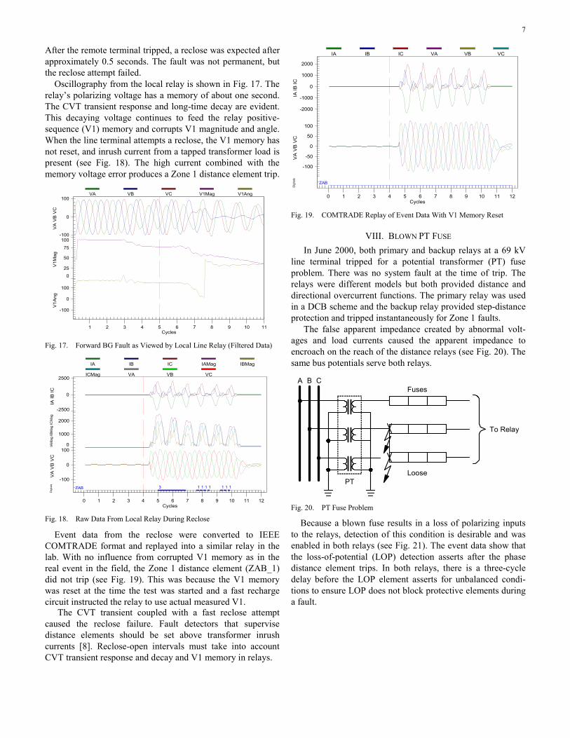
After the remote terminal tripped, a reclose was expected after approximately 0.5 seconds. The fault was not permanent, but the reclose attempt failed.
Oscillography from the local relay is shown in Fig. 17. The relay’s polarizing voltage has a memory of about one second. The CVT transient response and long-time decay are evident. This decaying voltage continues to feed the relay positive-sequence (V1) memory and corrupts V1 magnitude and angle. When the line terminal attempts a reclose, the V1 memory has not reset, and inrush current from a tapped transformer load is present (see Fig. 18). The high current combined with the memory voltage error produces a Zone 1 distance element trip.
-100
0
100
0
25
50
75
100
-100
0
100
1 2 3 4 5 6 7 8 9 10 11
VA
VB
VC
V1M
agV
1Ang
Cycles
VA VB VC V1Mag V1Ang
Fig. 17. Forward BG Fault as Viewed by Local Line Relay (Filtered Data)
ZAB 3 1 1 1 1 1 1 1
-2500
0
2500
0
1000
2000
-100
0
100
0 1 2 3 4 5 6 7 8 9 10 11 12
IA IB
ICIA
Mag
IBM
ag IC
Mag
VA
VB
VC
Dig
itals
Cycles
IA IB IC IAMag IBMag
ICMag VA VB VC
Fig. 18. Raw Data From Local Relay During Reclose
Event data from the reclose were converted to IEEE COMTRADE format and replayed into a similar relay in the lab. With no influence from corrupted V1 memory as in the real event in the field, the Zone 1 distance element (ZAB_1) did not trip (see Fig. 19). This was because the V1 memory was reset at the time the test was started and a fast recharge circuit instructed the relay to use actual measured V1.
The CVT transient coupled with a fast reclose attempt caused the reclose failure. Fault detectors that supervise distance elements should be set above transformer inrush currents [8]. Reclose-open intervals must take into account CVT transient response and decay and V1 memory in relays.
ZAB
-2000
-1000
0
1000
2000
-100
-50
0
50
100
0 1 2 3 4 5 6 7 8 9 10 11 12
IA IB
ICV
A V
B V
CD
igita
ls
Cycles
IA IB IC VA VB VC
Fig. 19. COMTRADE Replay of Event Data With V1 Memory Reset
VIII. BLOWN PT FUSE In June 2000, both primary and backup relays at a 69 kV
line terminal tripped for a potential transformer (PT) fuse problem. There was no system fault at the time of trip. The relays were different models but both provided distance and directional overcurrent functions. The primary relay was used in a DCB scheme and the backup relay provided step-distance protection and tripped instantaneously for Zone 1 faults.
The false apparent impedance created by abnormal volt-ages and load currents caused the apparent impedance to encroach on the reach of the distance relays (see Fig. 20). The same bus potentials serve both relays.
To Relay
Fuses
Loose
A B C
PT
Fig. 20. PT Fuse Problem
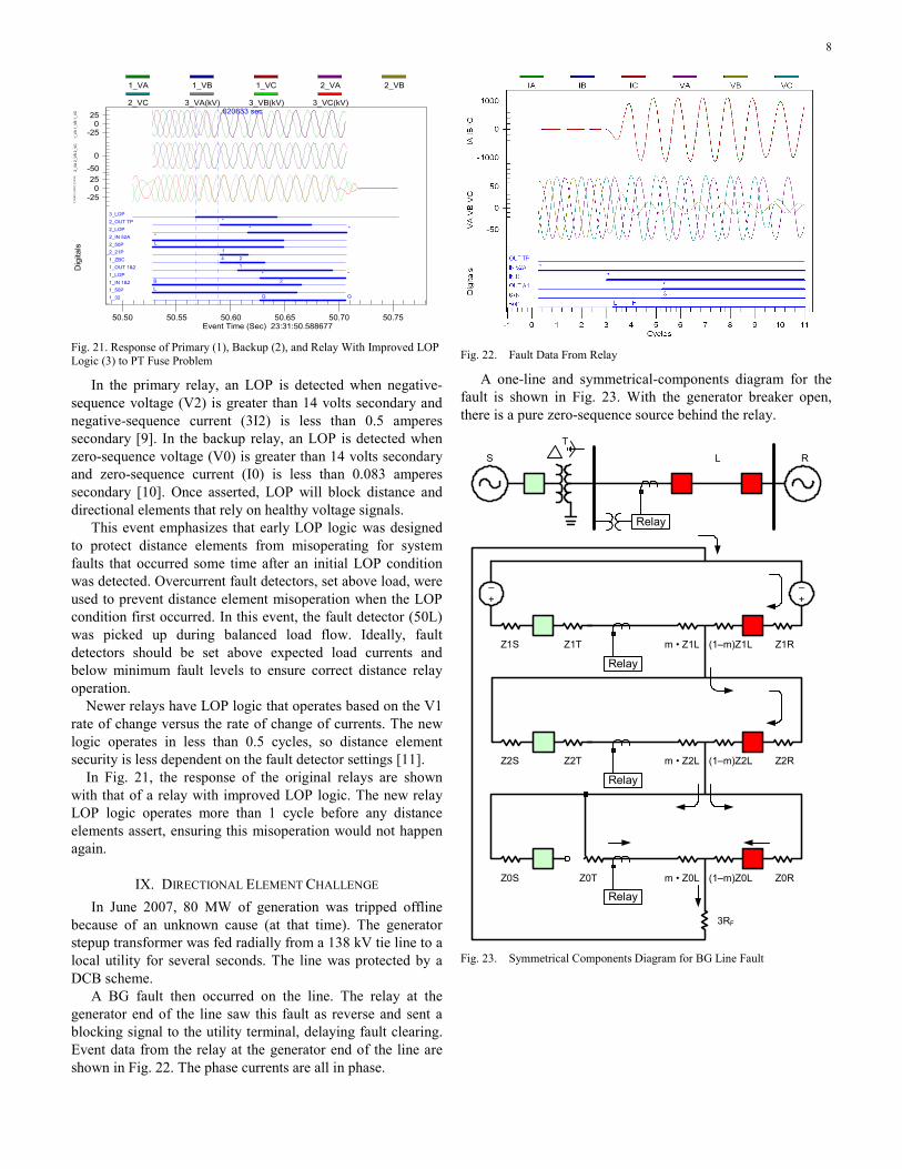
Because a blown fuse results in a loss of polarizing inputs to the relays, detection of this condition is desirable and was enabled in both relays (see Fig. 21). The event data show that the loss-of-potential (LOP) detection asserts after the phase distance element trips. In both relays, there is a three-cycle delay before the LOP element asserts for unbalanced condi-tions to ensure LOP does not block protective elements during a fault.
8
1_32 Q Q1_50P L1_IN 1&2 B 21_LOP * *1_OUT 1&2 11_ZBC 4 22_21P 12_50P L2_IN 52A *2_LOP * *2_OUT TP *3_LOP
-250
25
-500
-250
25
50.50 50.55 50.60 50.65 50.70 50.75
.020833 sec
1_VA
1_V
B 1_
VC2_
VA 2
_VB
2_VC
3_VA
(kV)
3_V
B(kV
) 3_V
C(kV
)
Dig
itals
Event Time (Sec) 23:31:50.588677
1_VA 1_VB 1_VC 2_VA 2_VB
2_VC 3_VA(kV) 3_VB(kV) 3_VC(kV)
Fig. 21. Response of Primary (1), Backup (2), and Relay With Improved LOP Logic (3) to PT Fuse Problem
In the primary relay, an LOP is detected when negative-sequence voltage (V2) is greater than 14 volts secondary and negative-sequence current (3I2) is less than 0.5 amperes secondary [9]. In the backup relay, an LOP is detected when zero-sequence voltage (V0) is greater than 14 volts secondary and zero-sequence current (I0) is less than 0.083 amperes secondary [10]. Once asserted, LOP will block distance and directional elements that rely on healthy voltage signals.
This event emphasizes that early LOP logic was designed to protect distance elements from misoperating for system faults that occurred some time after an initial LOP condition was detected. Overcurrent fault detectors, set above load, were used to prevent distance element misoperation when the LOP condition first occurred. In this event, the fault detector (50L) was picked up during balanced load flow. Ideally, fault detectors should be set above expected load currents and below minimum fault levels to ensure correct distance relay operation.
Newer relays have LOP logic that operates based on the V1 rate of change versus the rate of change of currents. The new logic operates in less than 0.5 cycles, so distance element security is less dependent on the fault detector settings [11].
In Fig. 21, the response of the original relays are shown with that of a relay with improved LOP logic. The new relay LOP logic operates more than 1 cycle before any distance elements assert, ensuring this misoperation would not happen again.
IX. DIRECTIONAL ELEMENT CHALLENGE In June 2007, 80 MW of generation was tripped offline
because of an unknown cause (at that time). The generator stepup transformer was fed radially from a 138 kV tie line to a local utility for several seconds. The line was protected by a DCB scheme.
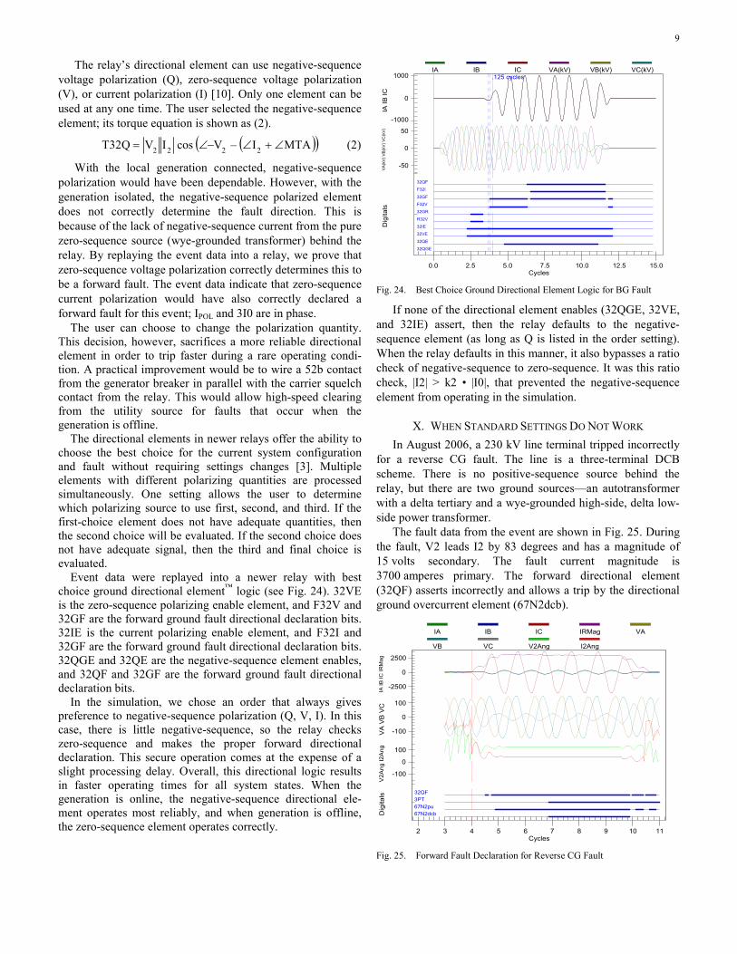
A BG fault then occurred on the line. The relay at the generator end of the line saw this fault as reverse and sent a blocking signal to the utility terminal, delaying fault clearing. Event data from the relay at the generator end of the line are shown in Fig. 22. The phase currents are all in phase.
Fig. 22. Fault Data From Relay
A one-line and symmetrical-components diagram for the fault is shown in Fig. 23. With the generator breaker open, there is a pure zero-sequence source behind the relay.
Relay
S
T
L R
–+
–+
Relay
Relay
Relay
Z2S Z2T m • Z2L (1–m)Z2L Z2R
Z1S Z1T m • Z1L (1–m)Z1L Z1R
Z0S Z0T m • Z0L (1–m)Z0L Z0R
3RF
Fig. 23. Symmetrical Components Diagram for BG Line Fault
9
The relay’s directional element can use negative-sequence voltage polarization (Q), zero-sequence voltage polarization (V), or current polarization (I) [10]. Only one element can be used at any one time. The user selected the negative-sequence element; its torque equation is shown as (2).
( )( )MTAI–VcosIVQ32T 2222 ∠+∠−∠= (2)
With the local generation connected, negative-sequence polarization would have been dependable. However, with the generation isolated, the negative-sequence polarized element does not correctly determine the fault direction. This is because of the lack of negative-sequence current from the pure zero-sequence source (wye-grounded transformer) behind the relay. By replaying the event data into a relay, we prove that zero-sequence voltage polarization correctly determines this to be a forward fault. The event data indicate that zero-sequence current polarization would have also correctly declared a forward fault for this event; IPOL and 3I0 are in phase.
The user can choose to change the polarization quantity. This decision, however, sacrifices a more reliable directional element in order to trip faster during a rare operating condi-tion. A practical improvement would be to wire a 52b contact from the generator breaker in parallel with the carrier squelch contact from the relay. This would allow high-speed clearing from the utility source for faults that occur when the generation is offline.
The directional elements in newer relays offer the ability to choose the best choice for the current system configuration and fault without requiring settings changes [3]. Multiple elements with different polarizing quantities are processed simultaneously. One setting allows the user to determine which polarizing source to use first, second, and third. If the first-choice element does not have adequate quantities, then the second choice will be evaluated. If the second choice does not have adequate signal, then the third and final choice is evaluated.
Event data were replayed into a newer relay with best choice ground directional element™ logic (see Fig. 24). 32VE is the zero-sequence polarizing enable element, and F32V and 32GF are the forward ground fault directional declaration bits. 32IE is the current polarizing enable element, and F32I and 32GF are the forward ground fault directional declaration bits. 32QGE and 32QE are the negative-sequence element enables, and 32QF and 32GF are the forward ground fault directional declaration bits.
In the simulation, we chose an order that always gives preference to negative-sequence polarization (Q, V, I). In this case, there is little negative-sequence, so the relay checks zero-sequence and makes the proper forward directional declaration. This secure operation comes at the expense of a slight processing delay. Overall, this directional logic results in faster operating times for all system states. When the generation is online, the negative-sequence directional ele-ment operates most reliably, and when generation is offline, the zero-sequence element operates correctly.
32QGE
32QE
32VE
32IE
R32V
32GR
F32V
32GF
F32I
32QF
-1000
0
1000
-50
0
50
0.0 2.5 5.0 7.5 10.0 12.5 15.0
.125 cycles
IA IB
ICV
A(k
V) V
B(k
V) V
C(k
V)
Dig
itals
Cycles
IA IB IC VA(kV) VB(kV) VC(kV)
Fig. 24. Best Choice Ground Directional Element Logic for BG Fault
If none of the directional element enables (32QGE, 32VE, and 32IE) assert, then the relay defaults to the negative-sequence element (as long as Q is listed in the order setting). When the relay defaults in this manner, it also bypasses a ratio check of negative-sequence to zero-sequence. It was this ratio check, |I2| > k2 • |I0|, that prevented the negative-sequence element from operating in the simulation.
X. WHEN STANDARD SETTINGS DO NOT WORK In August 2006, a 230 kV line terminal tripped incorrectly
for a reverse CG fault. The line is a three-terminal DCB scheme. There is no positive-sequence source behind the relay, but there are two ground sources—an autotransformer with a delta tertiary and a wye-grounded high-side, delta low-side power transformer.
The fault data from the event are shown in Fig. 25. During the fault, V2 leads I2 by 83 degrees and has a magnitude of 15 volts secondary. The fault current magnitude is 3700 amperes primary. The forward directional element (32QF) asserts incorrectly and allows a trip by the directional ground overcurrent element (67N2dcb).
67N2dcb67N2pu3PT32QF
-2500
0
2500
-100
0
100
-100
0
100
2 3 4 5 6 7 8 9 10 11
IA IB
IC IR
Mag
VA
VB
VC
V2A
ng I2
Ang
Dig
itals
Cycles
IA IB IC IRMag VA
VB VC V2Ang I2Ang
Fig. 25. Forward Fault Declaration for Reverse CG Fault
10
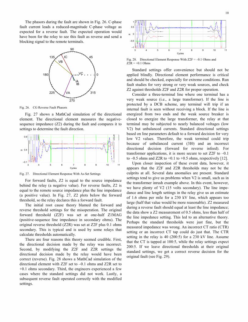
The phasors during the fault are shown in Fig. 26. C-phase fault current leads a reduced-magnitude C-phase voltage as expected for a reverse fault. The expected operation would have been for the relay to see this fault as reverse and send a blocking signal to the remote terminals.
0
45
90
135
180
225
270
315
IAIB
IC
VA
VB
VC
Fig. 26. CG Reverse Fault Phasors
Fig. 27 shows a MathCad simulation of the directional element. The directional element measures the negative-sequence impedance (Z2) during the fault and compares it to settings to determine the fault direction.
3 4 5 6 7 8 9 10 11Cycles
m
0.9
0.4
–0.1
Fig. 27. Directional Element Response With As-Set Settings
For forward faults, Z2 is equal to the source impedance behind the relay (a negative value). For reverse faults, Z2 is equal to the remote source impedance plus the line impedance (a positive value). In Fig. 27, Z2 plots below the forward threshold, so the relay declares this a forward fault.
The initial root cause theory blamed the forward and reverse threshold settings for the misoperation. The original forward threshold (Z2F) was set at one-half Z1MAG (positive-sequence line impedance in secondary ohms). The original reverse threshold (Z2R) was set at Z2F plus 0.1 ohms secondary. This is typical and is used by some relays that calculate thresholds automatically.
There are four reasons this theory seemed credible. First, the directional decision made by the relay was incorrect. Second, by modifying the Z2F and Z2R settings the directional decision made by the relay would have been correct (reverse). Fig. 28 shows a MathCad simulation of the directional element with Z2F set to –0.1 ohms and Z2R set to +0.1 ohms secondary. Third, the engineers experienced a few cases where the standard settings did not work. Lastly, a subsequent reverse fault operated correctly with the modified settings.
3 4 5 6 7 8 9 10 11Cycles
m
1
0
–1
–0.5
0.5
Fig. 28. Directional Element Response With Z2F = –0.1 Ohms and Z2R = +0.1 Ohms
Standard settings offer convenience but should not be applied blindly. Directional element performance is critical and should be checked, especially for extreme conditions. Run fault studies for very strong or very weak sources, and check Z2 against thresholds Z2F and Z2R for proper operation.
Consider a three-terminal line where one terminal has a very weak source (i.e., a large transformer). If the line is protected by a DCB scheme, any terminal will trip if an internal fault is seen without receiving a block. If the line is energized from two ends and the weak source breaker is closed to energize the large transformer, the relay at that terminal may be subjected to nearly balanced voltages (low V2) but unbalanced currents. Standard directional settings based on line parameters default to a forward decision for very low V2 values. Therefore, the weak terminal could trip because of unbalanced current (3I0) and an incorrect directional decision (forward for reverse infeed). For transformer applications, it is more secure to set Z2F to –0.1 to –0.5 ohms and Z2R to +0.1 to +0.5 ohms, respectively [12].
Upon closer inspection of these event data, however, it appears that the Z2F and Z2R thresholds may not be the culprits at all. Several data anomalies are present. Standard settings tend to give us problems when V2 is small, such as in the transformer inrush example above. In this event, however, we have plenty of V2 (15 volts secondary). The line impe-dance and line length settings in the relay give us an estimate of 1.6 ohms per mile for a 230 kV line, which appears too large (half that value would be more reasonable). Z2 measured during a reverse fault should equal at least the line impedance; the data show a Z2 measurement of 0.5 ohms, less than half of the line impedance setting. This led to an alternative theory. Perhaps the standard thresholds were just fine, but the measured impedance was wrong. An incorrect CT ratio (CTR) setting or an incorrect CT tap could do just that. The CTR setting in the relay is 40 (200:5) for a 230 kV line. Assume that the CT is tapped at 100:5, while the relay settings expect 200:5. If we leave directional thresholds at their original standard settings, we get a correct reverse decision for the original fault (see Fig. 29).
11
3 4 5 6 7 8 9 10 11Cycles
m
2
1
0
0.5
1.5
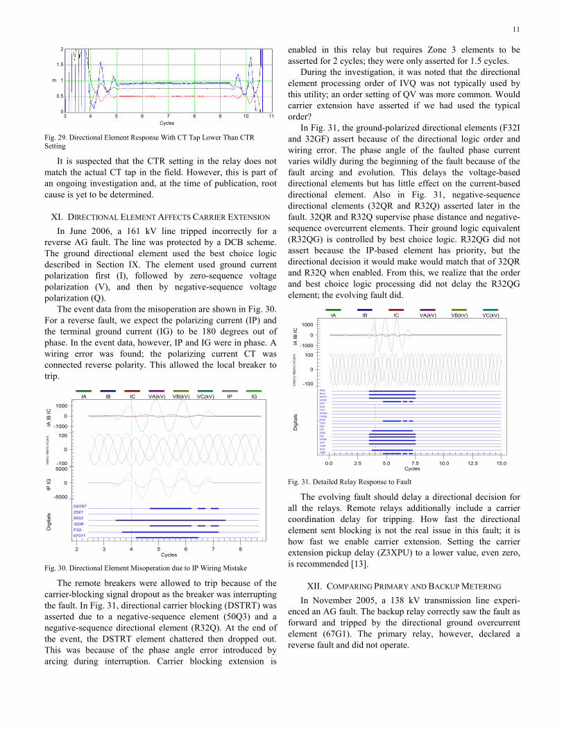
Fig. 29. Directional Element Response With CT Tap Lower Than CTR Setting
It is suspected that the CTR setting in the relay does not match the actual CT tap in the field. However, this is part of an ongoing investigation and, at the time of publication, root cause is yet to be determined.
XI. DIRECTIONAL ELEMENT AFFECTS CARRIER EXTENSION In June 2006, a 161 kV line tripped incorrectly for a
reverse AG fault. The line was protected by a DCB scheme. The ground directional element used the best choice logic described in Section IX. The element used ground current polarization first (I), followed by zero-sequence voltage polarization (V), and then by negative-sequence voltage polarization (Q).
The event data from the misoperation are shown in Fig. 30. For a reverse fault, we expect the polarizing current (IP) and the terminal ground current (IG) to be 180 degrees out of phase. In the event data, however, IP and IG were in phase. A wiring error was found; the polarizing current CT was connected reverse polarity. This allowed the local breaker to trip.
67G1TF32I32QR50G3Z3XTDSTRT
-1000
0
1000
-100
0
100
-5000
0
5000
2 3 4 5 6 7 8
IA IB
ICVA
(kV)
VB(
kV) V
C(k
V)IP
IGD
igita
ls
Cycles
IA IB IC VA(kV) VB(kV) VC(kV) IP IG
Fig. 30. Directional Element Misoperation due to IP Wiring Mistake
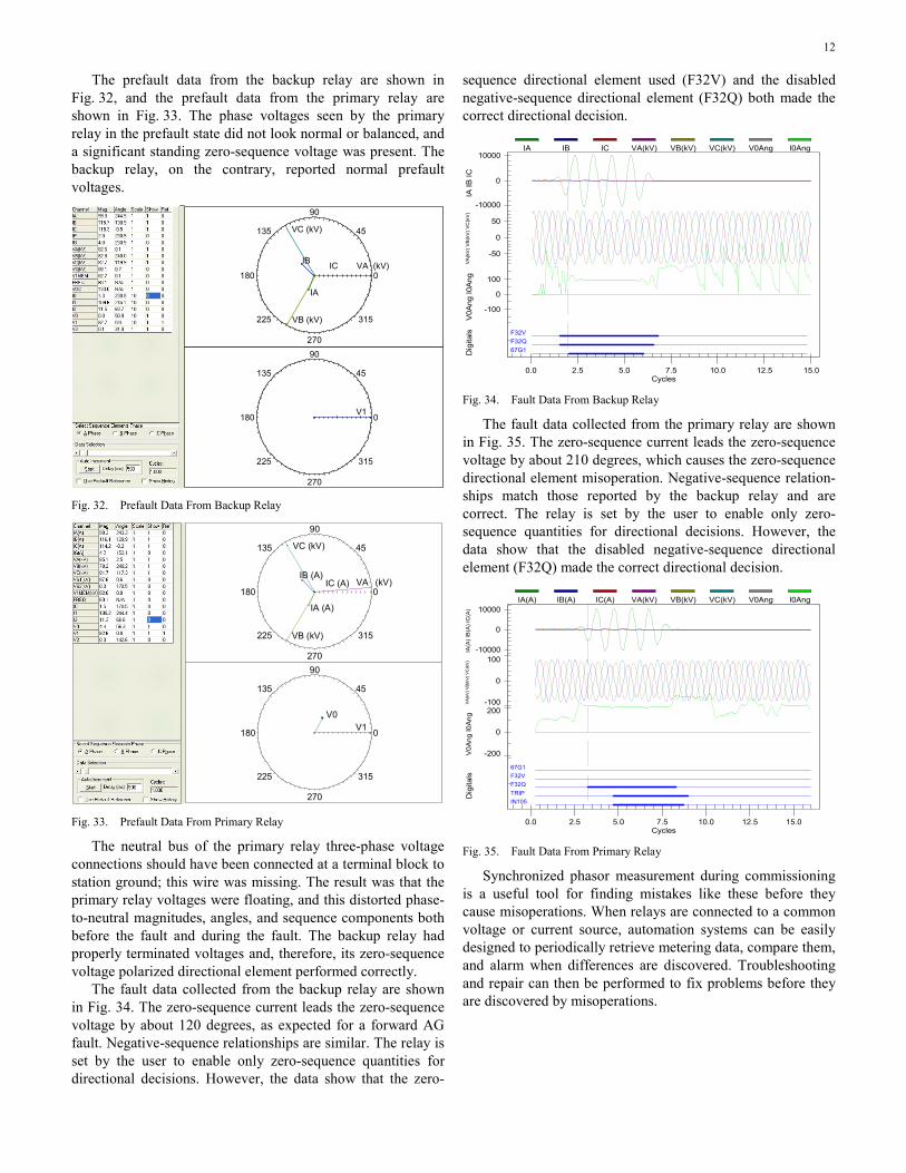
The remote breakers were allowed to trip because of the carrier-blocking signal dropout as the breaker was interrupting the fault. In Fig. 31, directional carrier blocking (DSTRT) was asserted due to a negative-sequence element (50Q3) and a negative-sequence directional element (R32Q). At the end of the event, the DSTRT element chattered then dropped out. This was because of the phase angle error introduced by arcing during interruption. Carrier blocking extension is
enabled in this relay but requires Zone 3 elements to be asserted for 2 cycles; they were only asserted for 1.5 cycles.
During the investigation, it was noted that the directional element processing order of IVQ was not typically used by this utility; an order setting of QV was more common. Would carrier extension have asserted if we had used the typical order?
In Fig. 31, the ground-polarized directional elements (F32I and 32GF) assert because of the directional logic order and wiring error. The phase angle of the faulted phase current varies wildly during the beginning of the fault because of the fault arcing and evolution. This delays the voltage-based directional elements but has little effect on the current-based directional element. Also in Fig. 31, negative-sequence directional elements (32QR and R32Q) asserted later in the fault. 32QR and R32Q supervise phase distance and negative-sequence overcurrent elements. Their ground logic equivalent (R32QG) is controlled by best choice logic. R32QG did not assert because the IP-based element has priority, but the directional decision it would make would match that of 32QR and R32Q when enabled. From this, we realize that the order and best choice logic processing did not delay the R32QG element; the evolving fault did.
32QR32GF32GR32VE32QGE32IE32QEF32IR32IF32QR32QF32QGR32QGF32VR32VZ3XTDSTRTNSTRT50G350Q3
-1000
0
1000
-100
0
100
0.0 2.5 5.0 7.5 10.0 12.5 15.0
IA IB
ICV
A(k
V) V
B(k
V) V
C(k
V)
Dig
itals
Cycles
IA IB IC VA(kV) VB(kV) VC(kV)
Fig. 31. Detailed Relay Response to Fault
The evolving fault should delay a directional decision for all the relays. Remote relays additionally include a carrier coordination delay for tripping. How fast the directional element sent blocking is not the real issue in this fault; it is how fast we enable carrier extension. Setting the carrier extension pickup delay (Z3XPU) to a lower value, even zero, is recommended [13].
XII. COMPARING PRIMARY AND BACKUP METERING In November 2005, a 138 kV transmission line experi-
enced an AG fault. The backup relay correctly saw the fault as forward and tripped by the directional ground overcurrent element (67G1). The primary relay, however, declared a reverse fault and did not operate.
12
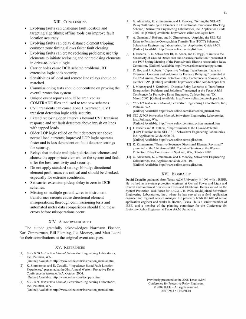
The prefault data from the backup relay are shown in Fig. 32, and the prefault data from the primary relay are shown in Fig. 33. The phase voltages seen by the primary relay in the prefault state did not look normal or balanced, and a significant standing zero-sequence voltage was present. The backup relay, on the contrary, reported normal prefault voltages.
0
45
90
135
180
225
270
315
V1
0
45
90
135
180
225
270
315
IA
IC
VC (kV)
VA
VB (kV)
(kV)IB
Fig. 32. Prefault Data From Backup Relay
0
45
90
135
180
225
270
315
IA (A)
IC (A)
VC (kV)
VA
VB (kV)
(kV)IB (A)
0
45
90
135
180
225
270
315
V1V0
Fig. 33. Prefault Data From Primary Relay
The neutral bus of the primary relay three-phase voltage connections should have been connected at a terminal block to station ground; this wire was missing. The result was that the primary relay voltages were floating, and this distorted phase-to-neutral magnitudes, angles, and sequence components both before the fault and during the fault. The backup relay had properly terminated voltages and, therefore, its zero-sequence voltage polarized directional element performed correctly.
The fault data collected from the backup relay are shown in Fig. 34. The zero-sequence current leads the zero-sequence voltage by about 120 degrees, as expected for a forward AG fault. Negative-sequence relationships are similar. The relay is set by the user to enable only zero-sequence quantities for directional decisions. However, the data show that the zero-
sequence directional element used (F32V) and the disabled negative-sequence directional element (F32Q) both made the correct directional decision.
67G1F32QF32V
-10000
0
10000
-50
0
50
-100
0
100
0.0 2.5 5.0 7.5 10.0 12.5 15.0
IA IB
ICV
A(k
V) V
B(k
V) V
C(k
V)
V0A
ng I0
Ang
Dig
itals
Cycles
IA IB IC VA(kV) VB(kV) VC(kV) V0Ang I0Ang
Fig. 34. Fault Data From Backup Relay
The fault data collected from the primary relay are shown in Fig. 35. The zero-sequence current leads the zero-sequence voltage by about 210 degrees, which causes the zero-sequence directional element misoperation. Negative-sequence relation-ships match those reported by the backup relay and are correct. The relay is set by the user to enable only zero-sequence quantities for directional decisions. However, the data show that the disabled negative-sequence directional element (F32Q) made the correct directional decision.
IN105TRIPF32QF32V67G1
-10000
0
10000
-100
0
100
-200
0
200
0.0 2.5 5.0 7.5 10.0 12.5 15.0
IA(A
) IB
(A) I
C(A
)VA
(kV)
VB(
kV) V
C(k
V)V
0Ang
I0A
ngD
igita
ls
Cycles
IA(A) IB(A) IC(A) VA(kV) VB(kV) VC(kV) V0Ang I0Ang
Fig. 35. Fault Data From Primary Relay
Synchronized phasor measurement during commissioning is a useful tool for finding mistakes like these before they cause misoperations. When relays are connected to a common voltage or current source, automation systems can be easily designed to periodically retrieve metering data, compare them, and alarm when differences are discovered. Troubleshooting and repair can then be performed to fix problems before they are discovered by misoperations.
13
XIII. CONCLUSIONS
• Evolving faults can challenge fault location andtargeting algorithms; offline tools can improve faultlocation accuracy.
• Evolving faults can delay distance element tripping;common zone timing allows faster fault clearing.
• Evolving faults can create reclosing problems; use tripelements to initiate reclosing and nonreclosing elementsin drive-to-lockout logic.
• Carrier holes cause DCB scheme problems; BTextension logic adds security.
• Sensitivities of local and remote line relays should bematched.
• Commissioning tests should concentrate on proving theoverall protection system.
• Unique event reports should be archived asCOMTRADE files and used to test new schemes.
• CVT transients can cause Zone 1 overreach; CVTtransient detection logic adds security.
• Extend reclosing open intervals beyond CVT transientresponse and set fault detectors above inrush on lineswith tapped loads.
• Older LOP logic relied on fault detectors set abovenormal load currents; improved LOP logic operatesfaster and is less dependent on fault detector settingsfor security.
• Relays that include multiple polarization schemes andchoose the appropriate element for the system and faultoffer the best sensitivity and security.
• Do not apply standard settings blindly; directionalelement performance is critical and should be checked,especially for extreme conditions.
• Set carrier extension pickup delay to zero in DCBschemes.
• Missing or multiple ground wires in instrumenttransformer circuits cause directional elementmisoperations; thorough commissioning tests andautomated meter data comparisons should find theseerrors before misoperations occur.
XIV. ACKNOWLEDGMENT
The author gratefully acknowledges Normann Fischer, Karl Zimmerman, Bill Fleming, Joe Mooney, and Matt Leoni for their contributions to the original event analyses.
XV. REFERENCES
[1] SEL-311B Instruction Manual, Schweitzer Engineering Laboratories, Inc., Pullman, WA. [Online] Available: http://www.selinc.com/instruction_manual.htm.
[2] K. Zimmerman and D. Costello, “Impedance-Based Fault Location Experience,” presented at the 31st Annual Western Protective Relay Conference in Spokane, WA, October 2004. [Online] Available: http://www.selinc.com/techpprs.htm.
[3] SEL-311C Instruction Manual, Schweitzer Engineering Laboratories, Inc., Pullman, WA. [Online] Available: http://www.selinc.com/instruction_manual.htm.
[4] G. Alexander, K. Zimmerman, and J. Mooney, “Setting the SEL-421 Relay With Sub-Cycle Elements in a Directional Comparison Blocking Scheme,” Schweitzer Engineering Laboratories, Inc. Application Guide 2007-10. [Online] Available: http://www.selinc.com/aglist.htm.
[5] A. Guzman, J. Roberts, and K. Zimmerman, “Applying the SEL-321 Relay to Permissive Overreaching Transfer Trip (POTT) Schemes,” Schweitzer Engineering Laboratories, Inc. Application Guide 95-29. [Online] Available: http://www.selinc.com/aglist.htm.
[6] J. Roberts, E. O. Schweitzer III, R. Arora, and E. Poggi, “Limits to the Sensitivity of Ground Directional and Distance Protection,” presented at the 1997 Spring Meeting of the Pennsylvania Electric Association Relay Committee. [Online] Available: http://www.selinc.com/techpprs.htm.
[7] D. Hou and J. Roberts, “Capacitive Voltage Transformers: Transient Overreach Concerns and Solutions for Distance Relaying,” presented at the 22nd Annual Western Protective Relay Conference in Spokane, WA, October 1995. [Online] Available: http://www.selinc.com/techpprs.htm.
[8] J. Mooney and S. Samineni, “Distance Relay Response to Transformer Energization: Problems and Solutions,” presented at the Texas A&M Conference for Protective Relay Engineers, College Station, TX, March 2007. [Online] Available: http://www.selinc.com/techpprs.htm.
[9] SEL-321 Instruction Manual, Schweitzer Engineering Laboratories, Inc., Pullman, WA. [Online] Available: http://www.selinc.com/instruction_manual.htm.
[10] SEL-221G5 Instruction Manual, Schweitzer Engineering Laboratories, Inc., Pullman, WA. [Online] Available: http://www.selinc.com/instruction_manual.htm.
[11] J. Roberts and R. Folkers, “Improvements to the Loss-of-Potential (LOP) Function in the SEL-321,” Schweitzer Engineering Laboratories, Inc. Application Guide 2000-05. [Online] Available: http://www.selinc.com/aglist.htm.
[12] K. Zimmerman, “Negative-Sequence Directional Element Revisited,” presented at the 21st Annual SEL Technical Seminar at the Western Protective Relay Conference in Spokane, WA, October 2005.
[13] G. Alexander, K. Zimmerman, and J. Mooney, Schweitzer Engineering Laboratories, Inc. Application Guide 2007-10. [Online] Available: http://www.selinc.com/aglist.htm.
XVI. BIOGRAPHY
David Costello graduated from Texas A&M University in 1991 with a BSEE. He worked as a system protection engineer at Central Power and Light and Central and Southwest Services in Texas and Oklahoma. He has served on the System Protection Task Force for ERCOT. In 1996, David joined Schweitzer Engineering Laboratories, Inc., where he has served as a field application engineer and regional service manager. He presently holds the title of senior application engineer and works in Boerne, Texas. He is a senior member of IEEE, and a member of the planning committee for the Conference for Protective Relay Engineers at Texas A&M University.
Previously presented at the 2008 Texas A&MConference for Protective Relay Engineers.
© 2008 IEEE – All rights reserved. 20070913 • TP6280-01


![Modeling and Analyzing Faults to Improve Election Process ... · fault trees for intrusion detection systems [23], Zhang et al. use fault trees for vulnerability evaluation [54],](https://img.pdfslide.net/doc/110x75/5dd0b87cd6be591ccb625e1d/modeling-and-analyzing-faults-to-improve-election-process-fault-trees-for-intrusion.jpg)