Embed Size (px)
Citation preview

National Aeronautics and Space Administration
www.nasa.gov 1
James F. Soeder
Raymond Beach
Larry Trase
NASA Glenn Research Center
Cleveland, Ohio
Lessons Learned From Developing Advanced
Space Power Systems Applied to the
Implementation of DC Terrestrial Micro-Grids
IEEE EnergyTech 2012
Case Western Reserve University
Cleveland, Ohio
May 29-30, 2012
https://ntrs.nasa.gov/search.jsp?R=20150010351 2018-06-18T04:38:53+00:00Z

National Aeronautics and Space Administration
www.nasa.gov
Discussion Topics
• Why is NASA interested in Smart Grid?
• Advanced Terrestrial Smart Grids
• ISS Description
• DC Power Challenges
– Fault Control
– Stability
• Wrap-up
2

National Aeronautics and Space Administration
www.nasa.gov
Why Intelligent Power / Smart Grid?
• NASA
– Provide a utility–like power
generation and distribution
capability with automated
operation to enable deep
space exploration and
settlement
• Terrestrial
– Increase the power delivery
capability and reliability of
the grid by integrating
renewables and energy
storage without major
increases to the
transmission and
generation infrastructure
3

National Aeronautics and Space Administration
www.nasa.gov 4
x Increased power demands x
x Utilization of diverse power sources (renewables) x
x Incorporation of large amounts of distributed energy storage x
x Seamless accommodation of Variable / Peak load demand x
x Failure diagnostics and prognostics for power components x
x Automated control for operations management, fault detection and system reconfiguration x
x Long term reliability / availability for exploration survivability and terrestrial users x
Exploration Power Terrestrial Power
Commonality of Challenges for Grid Developers
Power Grid Challenges
Exploration Power vs Terrestrial Power

National Aeronautics and Space Administration
www.nasa.gov
Advanced Terrestrial Smart Grids
5

National Aeronautics and Space Administration
www.nasa.gov
…the Grid of the Future?*
6
Residential
Commercial
Industrial
Storage
Wind Fuel Cell
Solar
*Courtesy of John Schneider, AEP

National Aeronautics and Space Administration
www.nasa.gov 7
Advanced Power Grid Hierarchy
Mini-Grid
Appliances HVAC Entertainment Lighting
S/A Battery Flywheel
Mini-Grid
Transmission Grid
Micro-grid
Mini-Grid Mini-Grid
AC Bus AC/DC
DC Bus
Distribution Grid
FES Flow Battery
Pumped Hydro
Hybrid
Vehicle

National Aeronautics and Space Administration
www.nasa.gov 8
More Advanced Power Grid Hierarchy
Mini-Grid
Appliances HVAC Entertainment Lighting S/A Battery Flywheel
Mini-Grid
Transmission Grid
Micro-grid
Mini-Grid Mini-Grid
DC Bus
FES Flow Battery
Pumped
Hydro
Hybrid
Vehicle
DC Bus AC/DC
AC Bus

National Aeronautics and Space Administration
www.nasa.gov
Why DC Micro grids?
• DC powered electrical devices make up 50 to 80%* of the
load in many buildings
– Computing equipment
– LED lighting will become more common
• Variable speed drives are penetrating into the appliance
market.
• Many renewables such as solar / wind / batteries (flow and
non-flow) fuel cells flywheels etc. are already compatible
with DC systems (Have DC outputs)
9
* Nextek Power Systems

National Aeronautics and Space Administration
www.nasa.gov
DC Distribution and the International Space
Station
10
National Aeronautics and Space Administration
www.nasa.gov
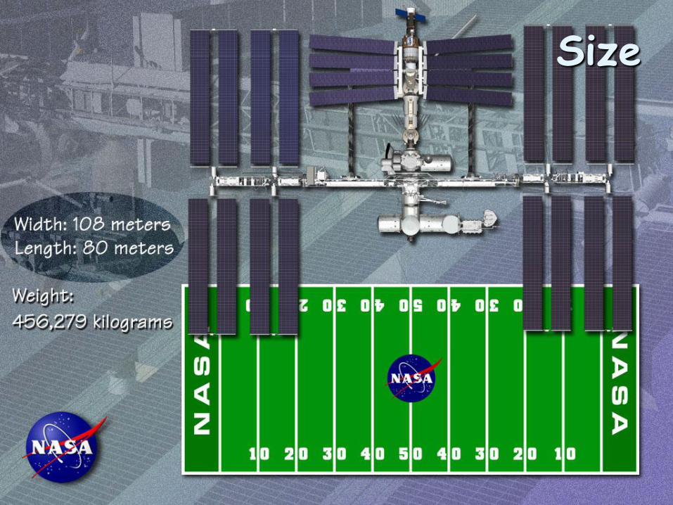
Size

National Aeronautics and Space Administration
www.nasa.gov
International Space Station
Power System Characteristics • Power 75 kW average
• Eight independent power
channels -- 9.75 kW
• Solar array power 200+ kW
• Planar silicon arrays
• 18% Efficient
• NiH battery storage – 3 per
channel (2 ORUs)
• 76 cells @ 81 amp*hrs /
battery
• Distribution
– 116 - 170 V primary
– 120 V secondary
• Contingency power > 1 orbit
• System lifetime of 15+ years

National Aeronautics and Space Administration
www.nasa.gov 13
ISS Primary Grid

National Aeronautics and Space Administration
www.nasa.gov
Reg
Reg
Battery
Reg
Reg
Reg
Reg
Reg
Reg
L
L
L
L
•
•
• •
•
•
•
•
Considerations in DC Distribution Systems
• Stability with multiple power converters
• Coordinated DC fault control @ high voltage
Primary Secondary

National Aeronautics and Space Administration
www.nasa.gov
Stability
15

National Aeronautics and Space Administration
www.nasa.gov
Power System Stability
16
SOURCE LOADZS ZL
• If |ZS| < |ZL| for all frequencies,
then the system is stable
• When |ZS| > |ZL|, further analysis
is needed to determine system stability.
From SAE Spec AS5698

National Aeronautics and Space Administration
www.nasa.gov
Power System Stability
17
-30
-20
-10
0
10
20
10 100 1000 10000 100000
Frequency (Hz)
Per
Un
it O
hm
s (
dB
)
ACCEPTABLE REGION
Normalized load Input Impedance Limit
• If |ZS| < |ZL| for all
frequencies, then the
system is stable

National Aeronautics and Space Administration
www.nasa.gov
Power System Stability
18
• When |ZS| > |ZL|, further analysis
is needed to determine system stability
• Using the Nyquist criterion,
small-signal system stability can
be determined by whether
the curve of ZS/ZL circles the
(-1,0) in the S-plane
• The forbidden region on this diagram
establishes a system stability margin.
From SAE Spec AS5698

National Aeronautics and Space Administration
www.nasa.gov
Power System Stability Examples
19
Stable System Under damped but stable system
National Aeronautics and Space Administration
www.nasa.gov 20
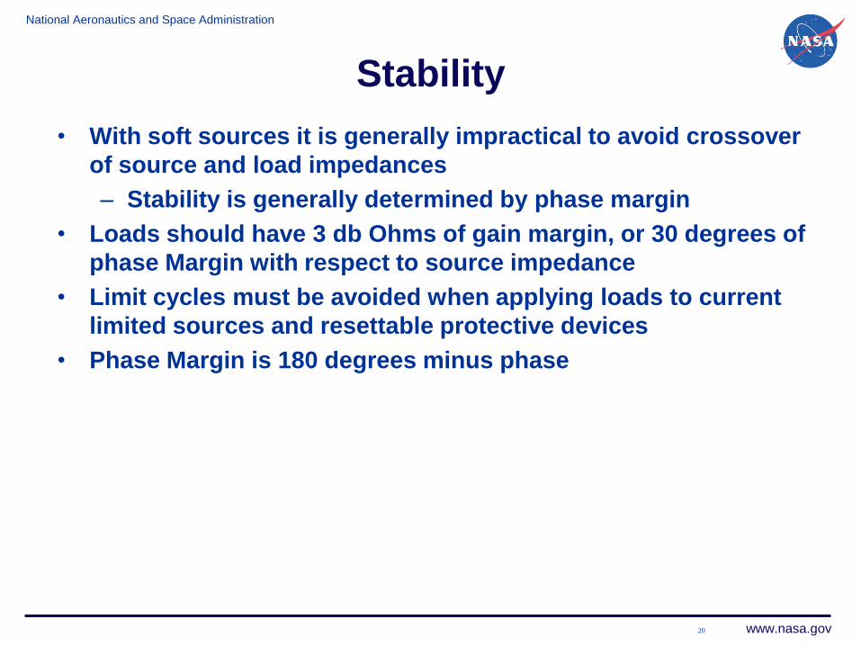
Stability
• With soft sources it is generally impractical to avoid crossover
of source and load impedances
– Stability is generally determined by phase margin
• Loads should have 3 db Ohms of gain margin, or 30 degrees of
phase Margin with respect to source impedance
• Limit cycles must be avoided when applying loads to current
limited sources and resettable protective devices
• Phase Margin is 180 degrees minus phase

National Aeronautics and Space Administration
www.nasa.gov
DC Fault Control
21

National Aeronautics and Space Administration
www.nasa.gov
DC Fault Control
• Fault Clearing for DC systems is inherently difficult
because the current never passes through zero.
• Challenges
– Clear the fault quickly with minimum stress on the
system
– Minimize the effect on other branches of the system
• Coordinated fault response
– Switch closest to the fault needs to trip first
• Form factor should be compact and lightweight
22

National Aeronautics and Space Administration
www.nasa.gov
DC Switchgear
23
Fuse Mech Relay Hybrid CL Solid
State
Resettable N Y Y Y
Mass B
Losses B
Coordination B
System Impacts B
Complexity B
B – Baseline
Y – Yes
Best
Better
Worse
Worst

National Aeronautics and Space Administration
www.nasa.gov 24
Mechanical Switch: Kilovac Vacuum Relay
Description
• AP350X “Bubba” -- Largest
space-rated switch
• Voltages:
• 270 Vdc continuous
• 350 Vdc 10 µsec
• Currents:
• 500 A continuous
• <5000 A surge
• Switching time: 10 msec
• Magnetic arc blow-out
• Low loss
• No current limiting
• System transients tend to be high
Kilovac 500 A Vacuum Switch
“Bubba”

National Aeronautics and Space Administration
www.nasa.gov
Hybrid Switch
25
Schematic of hybrid switch
Description
• Contains both mechanical and
Solid state components
• Solid state switch permits “soft” turn-
on and turn-off
• Mechanical switch provides low loss
in on-state
• Mechanical switch does not need to be
sized for interrupt
• Trip coordination can be tricky

National Aeronautics and Space Administration
www.nasa.gov
Current Limited RPC
26
Description
• Remote Power Controllers control
and protect electrical system
• Current limited RPCs provide
absolute protection for system wiring
• Can be reset
• Can be paralleled to increase current
handling capability
- Unlike fuses or circuit breakers
• Utilizes an innovative v2t trip curve.
• Can distinguish between sever and
slight overload
• Multi-level trip coordination is easily
implemented
- Avoids ambiguity of using i2t trip
curves
0.1
1
10
100
1000
0.01 0.1 1 10 100 1000Trip Time (sec)
Sw
itch
Vo
ltag
e D
rop

National Aeronautics and Space Administration
www.nasa.gov
Switch Voltage Drop
RPCVsource
Load
V load
+ Vsw -
Psw = Load * Vsw
Description
• Utilizes switch voltage drop to determine trip time
• Can distinguish between sever and
slight overload
• Trip curve utilizes semiconductor „s safe
operating area
0.1
1
10
100
1000
0.01 0.1 1 10 100 1000Trip Time (sec)
Sw
itch
Vo
ltag
e D
rop
National Aeronautics and Space Administration
www.nasa.gov
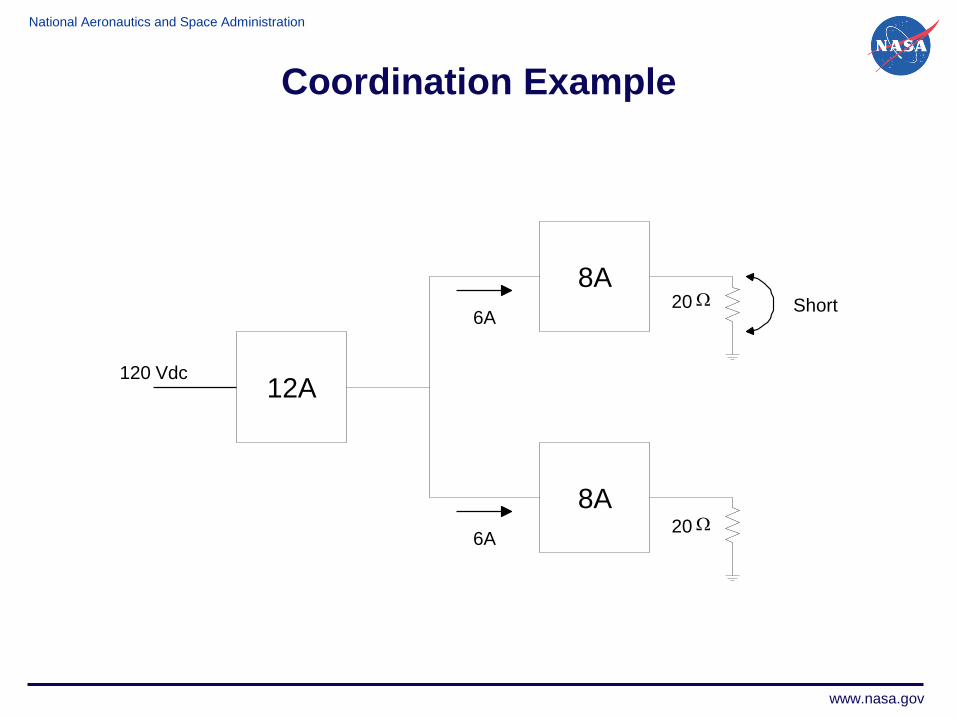
Coordination Example
12A
8A
8A
20 W
20 W
6A
6A
120 Vdc
Short

National Aeronautics and Space Administration
www.nasa.gov
Coordination Example
0.1
1
10
100
1000
0.01 0.1 1 10 100 1000Trip Time (sec)
Sw
itch
Vo
ltag
e D
rop
12A
8A
8A
20 W
20 W
8A
4A
120 Vdc
Short
80 V
40 V
80 V
0 V

National Aeronautics and Space Administration
www.nasa.gov
Wrap-Up
• Advanced DC terrestrial micro-grids can learn a great deal
from experience developing the International Space Station
Power System
• The negative impedance of multiple power converters in
series can pose stability challenges
• Fault control with soft sources such as power converters
and solar arrays needs to be accommodated
30

National Aeronautics and Space Administration
www.nasa.gov
References
• David Fox -- Hamilton Sundstrand Corp.
• James Soltis – NASA Glenn Research Center
• Nextek Corporation
31

National Aeronautics and Space Administration
www.nasa.gov
Back-up
32

National Aeronautics and Space Administration
www.nasa.gov
RPC
SSU
1 of 8 power channels
RBIRBI
RBI RBI RBI
DCSU
MBSU
RPC
RPC
DDCU
DDCU
DDCU
B
C
D
U
B
C
D
U
B
C
D
U
B
C
D
U
Challenges
• Evolution to accommodate peak
power
• Variable Loads with constrained
sources
• Automated operation
SSU – Sequential Shunt Unit
RBI – Remote Bus Isolator
DCSU – Direct Current Switching Unit
MBSU – Main Bus Switching Unit
DDCU – dc to dc Converter
RPC – Remote Power Controller
ISS Power Architecture

National Aeronautics and Space Administration
www.nasa.gov
Coordination Example
12A
8A
8A
20 W
20 W
8A
4A
120 Vdc
Short
80 V
40 V
80 V
0 V

National Aeronautics and Space Administration
www.nasa.gov
What is NASA‟s Interest In Smart Grid?
35
Planetary Surface Power
Systems
ISS Automation
Facility Sustainability
NASA‟s interest is in the development of technologies that benefit
space exploration and enable the Terrestrial Smart Grid
Deep Space Habitat