Embed Size (px)
Citation preview

LET’S GET
GETTING STARTED
GUIDE
NOW THAT YOU’RE HERE
STARTED
Vectorworks Spotlight Getting Started GuideCreated using: Vectorworks Spotlight 2016
© 2016 Nemetschek Vectorworks, Inc. All rights reserved. No part of this book may be reproduced or transmitted in any form by any means, electronic or mechanical, including photocopying, recording, faxing, emailing, posting online or by any information storage, and retrieval system, without prior written permission of the publisher. Published in the United States. Vectorworks is a registered trademark of Nemetschek Vectorworks, Inc., in the United States, and other countries. Windows is a registered trademark of Microsoft Corporation in the United States, and other countries. Macintosh is a trademark of Apple Computer, Inc., registered in the United States, and other countries. Adobe, Acrobat, and Reader are registered trademarks of Adobe Systems in the United States, and other countries. The information in this book is distributed on an “as is” basis, without warranty. While every precaution has been taken in the preparation of this book, neither the author nor Nemetschek Vectorworks, Inc., shall have any liability to any person or entity with respect to any loss or damage caused or alleged to be caused directly or indirectly by the information contained in this book or by the computer software described in it. For additional Vectorworks training information, or to purchase copies of this book, please call us, in the United States at (410) 290-5114 or visit Vectorworks.net/training online.
NVM.GSGVS-2016 v1.0
VECTORWORKS SPOTLIGHT GETTING STARTED GUIDE
3 | Vectorworks Spotlight 2016 Getting Started Guide
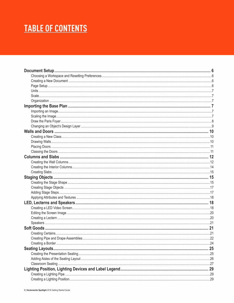
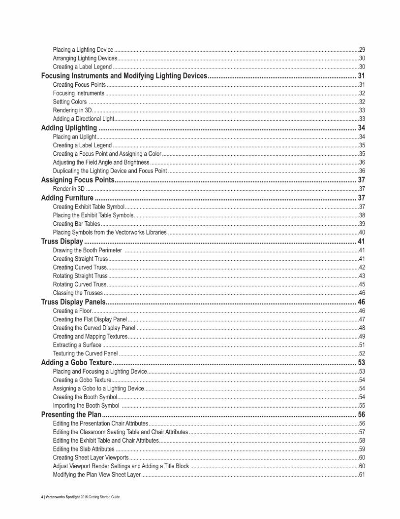
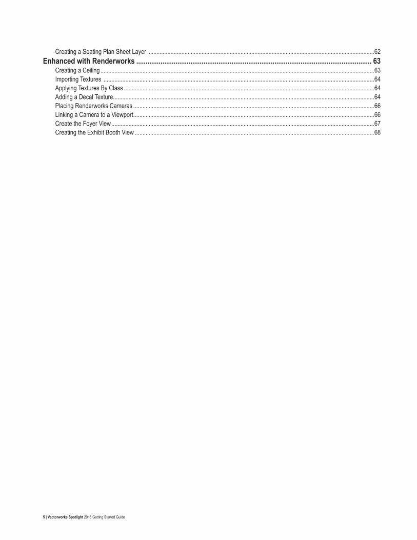
TABLE OF CONTENTS
Document Setup ..................................................................................................................................................... 6Choosing a Workspace and Resetting Preferences ..............................................................................................................................6Creating a New Document ....................................................................................................................................................................6Page Setup ............................................................................................................................................................................................6Units ......................................................................................................................................................................................................7Scale ......................................................................................................................................................................................................7Organization ..........................................................................................................................................................................................7
Importing the Base Plan ........................................................................................................................................ 7Importing an Image ................................................................................................................................................................................7Scaling the Image ..................................................................................................................................................................................7Draw the Paris Foyer .............................................................................................................................................................................8Changing an Object’s Design Layer ......................................................................................................................................................9
Walls and Doors ................................................................................................................................................... 10Creating a New Class ..........................................................................................................................................................................10Drawing Walls ......................................................................................................................................................................................10Placing Doors ......................................................................................................................................................................................11Classing the Doors ..............................................................................................................................................................................11
Columns and Slabs .............................................................................................................................................. 12Creating the Wall Columns ..................................................................................................................................................................12Creating the Interior Columns ..............................................................................................................................................................14Creating Slabs .....................................................................................................................................................................................15
Staging Objects .................................................................................................................................................... 15Creating the Stage Shape ...................................................................................................................................................................15Creating Stage Objects .......................................................................................................................................................................17Adding Stage Steps .............................................................................................................................................................................17Applying Attributes and Textures .........................................................................................................................................................18
LED, Lecterns and Speakers ............................................................................................................................... 18Creating a LED Video Screen..............................................................................................................................................................18Editing the Screen Image ....................................................................................................................................................................20Creating a Lectern ...............................................................................................................................................................................20Speakers .............................................................................................................................................................................................21
Soft Goods ............................................................................................................................................................ 21Creating Certains .................................................................................................................................................................................21Creating Pipe and Drape Assemblies ..................................................................................................................................................22Creating a Border ................................................................................................................................................................................24
Seating Layouts .................................................................................................................................................... 25Creating the Presentation Seating .......................................................................................................................................................25Adding Aisles of the Seating Layout ....................................................................................................................................................26Classroom Seating ..............................................................................................................................................................................27
Lighting Position, Lighting Devices and Label Legend .................................................................................... 29Creating a Lighting Pipe ......................................................................................................................................................................29Creating a Lighting Position .................................................................................................................................................................29
4 | Vectorworks Spotlight 2016 Getting Started Guide
Placing a Lighting Device ....................................................................................................................................................................29Arranging Lighting Devices ..................................................................................................................................................................30Creating a Label Legend .....................................................................................................................................................................30
Focusing Instruments and Modifying Lighting Devices ................................................................................... 31Creating Focus Points .........................................................................................................................................................................31Focusing Instruments ..........................................................................................................................................................................32Setting Colors .....................................................................................................................................................................................32Rendering in 3D ...................................................................................................................................................................................33Adding a Directional Light ....................................................................................................................................................................33
Adding Uplighting ................................................................................................................................................ 34Placing an Uplight ................................................................................................................................................................................34Creating a Label Legend .....................................................................................................................................................................35Creating a Focus Point and Assigning a Color ....................................................................................................................................35Adjusting the Field Angle and Brightness ............................................................................................................................................36Duplicating the Lighting Device and Focus Point ................................................................................................................................36
Assigning Focus Points ....................................................................................................................................... 37Render in 3D .......................................................................................................................................................................................37
Adding Furniture .................................................................................................................................................. 37Creating Exhibit Table Symbol .............................................................................................................................................................37Placing the Exhibit Table Symbols .......................................................................................................................................................38Creating Bar Tables .............................................................................................................................................................................39Placing Symbols from the Vectorworks Libraries ................................................................................................................................40
Truss Display ........................................................................................................................................................ 41Drawing the Booth Perimeter .............................................................................................................................................................41Creating Straight Truss ........................................................................................................................................................................41Creating Curved Truss .........................................................................................................................................................................42Rotating Straight Truss ........................................................................................................................................................................43Rotating Curved Truss .........................................................................................................................................................................45Classing the Trusses ...........................................................................................................................................................................46
Truss Display Panels ............................................................................................................................................ 46Creating a Floor ...................................................................................................................................................................................46Creating the Flat Display Panel ...........................................................................................................................................................47Creating the Curved Display Panel .....................................................................................................................................................48Creating and Mapping Textures ...........................................................................................................................................................49Extracting a Surface ............................................................................................................................................................................51Texturing the Curved Panel .................................................................................................................................................................52
Adding a Gobo Texture ........................................................................................................................................ 53Placing and Focusing a Lighting Device ..............................................................................................................................................53Creating a Gobo Texture......................................................................................................................................................................54Assigning a Gobo to a Lighting Device ................................................................................................................................................54Creating the Booth Symbol ..................................................................................................................................................................54Importing the Booth Symbol ...............................................................................................................................................................55
Presenting the Plan .............................................................................................................................................. 56Editing the Presentation Chair Attributes .............................................................................................................................................56Editing the Classroom Seating Table and Chair Attributes ..................................................................................................................57Editing the Exhibit Table and Chair Attributes ......................................................................................................................................58Editing the Slab Attributes ...................................................................................................................................................................59Creating Sheet Layer Viewports ..........................................................................................................................................................60Adjust Viewport Render Settings and Adding a Title Block .................................................................................................................60Modifying the Plan View Sheet Layer ..................................................................................................................................................61
5 | Vectorworks Spotlight 2016 Getting Started Guide
Creating a Seating Plan Sheet Layer ..................................................................................................................................................62Enhanced with Renderworks .............................................................................................................................. 63
Creating a Ceiling ................................................................................................................................................................................63Importing Textures ..............................................................................................................................................................................64Applying Textures By Class .................................................................................................................................................................64Adding a Decal Texture........................................................................................................................................................................64Placing Renderworks Cameras ...........................................................................................................................................................66Linking a Camera to a Viewport...........................................................................................................................................................66Create the Foyer View .........................................................................................................................................................................67Creating the Exhibit Booth View ..........................................................................................................................................................68
6 | Vectorworks Spotlight 2016 Getting Started Guide
GETTING STARTED WITH VECTORWORKS SPOTLIGHT
Document Setup
Choosing a Workspace and Resetting PreferencesBefore starting, you will need to switch to the Spotlight workspace, then reset your Vectorworks Preferences and the SmartCursor Settings. Resetting these settings will guarantee you have the same settings used in this guide.
1. Go to Tools > Workspaces > Spotlight.
2. Next, go to Tools > Options > Vectorworks Preferences.
3. Click Reset in the bottom left corner and then click Yes to confirm the reset action.
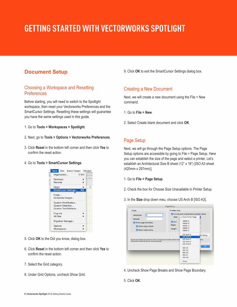
4. Go to Tools > SmartCursor Settings.
5. Click OK to the Did you know‚ dialog box.
6. Click Reset in the bottom left corner and then click Yes to confirm the reset action.
7. Select the Grid category.
8. Under Grid Options, uncheck Show Grid.
9. Click OK to exit the SmartCursor Settings dialog box.
Creating a New DocumentNext, we will create a new document using the File > New command.
1. Go to File > New.
2. Select Create blank document and click OK.
Page SetupNext, we will go through the Page Setup options. The Page Setup options are accessible by going to File > Page Setup. Here you can establish the size of the page and select a printer. Let’s establish an Architectural Size B sheet (12” x 18”) [ISO A3 sheet (420mm x 297mm)].
1. Go to File > Page Setup.
2. Check the box for Choose Size Unavailable in Printer Setup.
3. In the Size drop down meu, choose US Arch B [ISO A3].
4. Uncheck Show Page Breaks and Show Page Boundary.
5. Click OK.
7 | Vectorworks Spotlight 2016 Getting Started Guide
UnitsUnit settings are applied throughout the drawing, from the measurements that display on the rulers to those used in dimensions and worksheets. Unit options are accessible by go to File > Document Settings > Units. Let’s choose Feet and Inches [Meters] for our file.
1. Go to File > Document Settings > Units.
2. Choose either Feet and Inches or Meters from the Units list.
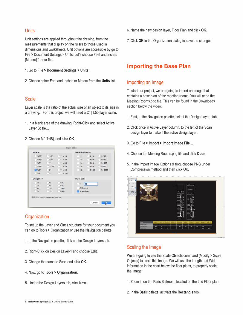
ScaleLayer scale is the ratio of the actual size of an object to its size in a drawing. For this project we will need a ¼” [1:50] layer scale.
1. In a blank area of the drawing, Right-Click and select Active Layer Scale…
2. Choose ¼” [1:48], and click OK.
OrganizationTo set up the Layer and Class structure for your document you can go to Tools > Organization or use the Navigation palette.
1. In the Navigation palette, click on the Design Layers tab.
2. Right-Click on Design Layer-1 and choose Edit.
3. Change the name to Scan and click OK.
4. Now, go to Tools > Organization.
5. Under the Design Layers tab, click New.
6. Name the new design layer, Floor Plan and click OK.
7. Click OK in the Organization dialog to save the changes.
Importing the Base Plan
Importing an ImageTo start our project, we are going to import an Image that contains a base plan of the meeting rooms. You will need the Meeting Rooms.png file. This can be found in the Downloads section below the video.
1. First, in the Navigation palette, select the Design Layers tab .
2. Click once in Active Layer column, to the left of the Scan design layer to make it the active design layer .
3. Go to File > Import > Import Image File…
4. Choose the Meeting Rooms.png file and click Open.
5. In the Import Image Options dialog, choose PNG under Compression method and then click OK.
Scaling the ImageWe are going to use the Scale Objects command (Modify > Scale Objects) to scale this Image. We will use the Length and Width information in the chart below the floor plans, to properly scale the Image.
1. Zoom in on the Paris Ballroom, located on the 2nd Floor plan.
2. In the Basic palette, activate the Rectangle tool.
8 | Vectorworks Spotlight 2016 Getting Started Guide
3. Make sure the first mode, Corner to Corner mode is active in the Tool bar.
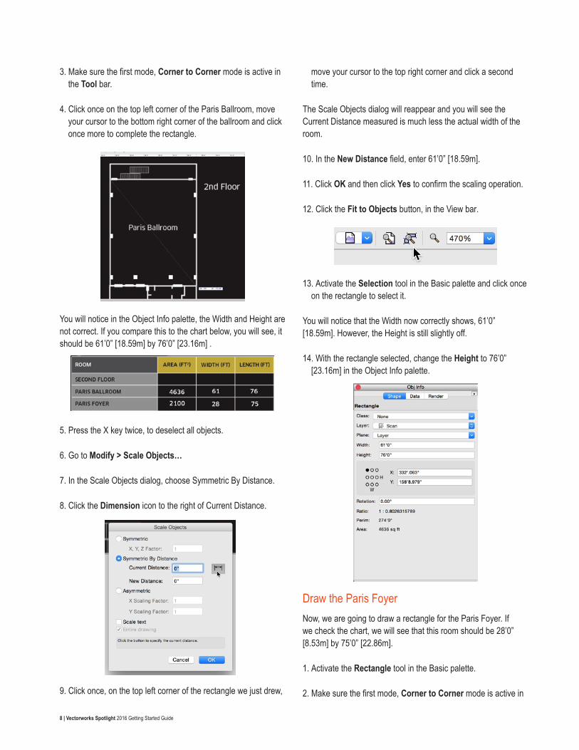
4. Click once on the top left corner of the Paris Ballroom, move your cursor to the bottom right corner of the ballroom and click once more to complete the rectangle.
You will notice in the Object Info palette, the Width and Height are not correct. If you compare this to the chart below, you will see, it should be 61’0” [18.59m] by 76’0” [23.16m] .
5. Press the X key twice, to deselect all objects.
6. Go to Modify > Scale Objects…
7. In the Scale Objects dialog, choose Symmetric By Distance.
8. Click the Dimension icon to the right of Current Distance.
9. Click once, on the top left corner of the rectangle we just drew,
move your cursor to the top right corner and click a second time.
The Scale Objects dialog will reappear and you will see the Current Distance measured is much less the actual width of the room.
10. In the New Distance field, enter 61’0” [18.59m].
11. Click OK and then click Yes to confirm the scaling operation.
12. Click the Fit to Objects button, in the View bar.
13. Activate the Selection tool in the Basic palette and click once on the rectangle to select it.
You will notice that the Width now correctly shows, 61’0” [18.59m]. However, the Height is still slightly off.
14. With the rectangle selected, change the Height to 76’0” [23.16m] in the Object Info palette.
Draw the Paris FoyerNow, we are going to draw a rectangle for the Paris Foyer. If we check the chart, we will see that this room should be 28’0” [8.53m] by 75’0” [22.86m].
1. Activate the Rectangle tool in the Basic palette.
2. Make sure the first mode, Corner to Corner mode is active in
9 | Vectorworks Spotlight 2016 Getting Started Guide
the Tool bar.
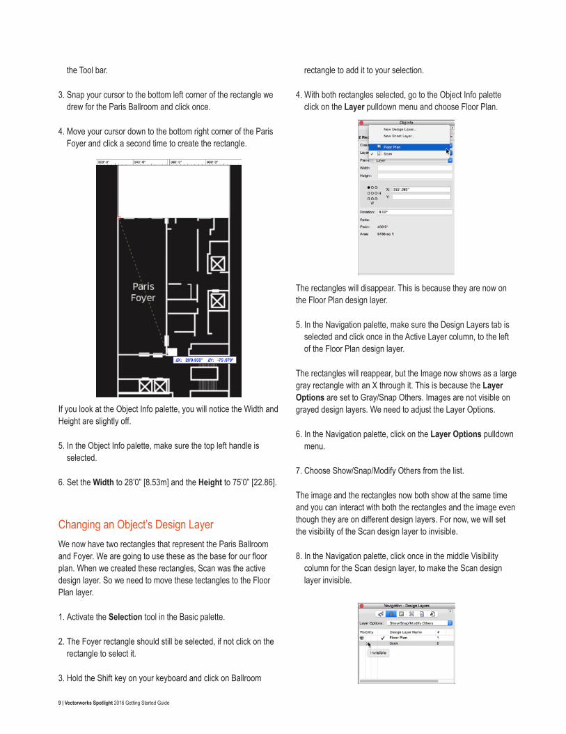
3. Snap your cursor to the bottom left corner of the rectangle we drew for the Paris Ballroom and click once.
4. Move your cursor down to the bottom right corner of the Paris Foyer and click a second time to create the rectangle.
If you look at the Object Info palette, you will notice the Width and Height are slightly off.
5. In the Object Info palette, make sure the top left handle is selected.
6. Set the Width to 28’0” [8.53m] and the Height to 75’0” [22.86].
Changing an Object’s Design LayerWe now have two rectangles that represent the Paris Ballroom and Foyer. We are going to use these as the base for our floor plan. When we created these rectangles, Scan was the active design layer. So we need to move these tectangles to the Floor Plan layer.
1. Activate the Selection tool in the Basic palette.
2. The Foyer rectangle should still be selected, if not click on the rectangle to select it.
3. Hold the Shift key on your keyboard and click on Ballroom
rectangle to add it to your selection.
4. With both rectangles selected, go to the Object Info palette click on the Layer pulldown menu and choose Floor Plan.
The rectangles will disappear. This is because they are now on the Floor Plan design layer.
5. In the Navigation palette, make sure the Design Layers tab is selected and click once in the Active Layer column, to the left of the Floor Plan design layer.
The rectangles will reappear, but the Image now shows as a large gray rectangle with an X through it. This is because the Layer Options are set to Gray/Snap Others. Images are not visible on grayed design layers. We need to adjust the Layer Options.
6. In the Navigation palette, click on the Layer Options pulldown menu.
7. Choose Show/Snap/Modify Others from the list.
The image and the rectangles now both show at the same time and you can interact with both the rectangles and the image even though they are on different design layers. For now, we will set the visibility of the Scan design layer to invisible.
8. In the Navigation palette, click once in the middle Visibility column for the Scan design layer, to make the Scan design layer invisible.
10 | Vectorworks Spotlight 2016 Getting Started Guide
9. Finally, click the Fit to Objects button in the View bar to center the drawing over the rectangles.
Walls and Doors
Creating a New ClassFirst, we need to create a new class for our walls.
1. Go to Tools > Organization.
2. Switch to the Classes tab.
3. Click New to create a new class.
4. In the New Class dialog, name the class Walls and click OK.
5. Click once in the Active Class column, to the left of the new Walls class to make it the active class.
6. Click OK to save the changes and exit the Organization dialog.
Drawing WallsNext, we are going to draw the walls for these two rooms. We will use the Wall tool from the Building Shell tool set.
1. Switch to the Building Shell tool set in the Tool Sets palette.
2. Activate the Wall tool.
3. In the Tool bar, make sure the Left Control Line, Wall Control Line and Rectangle modes are active.
4. Also, make sure that <Unstyled> is selected in the Wall Style pulldown menu.
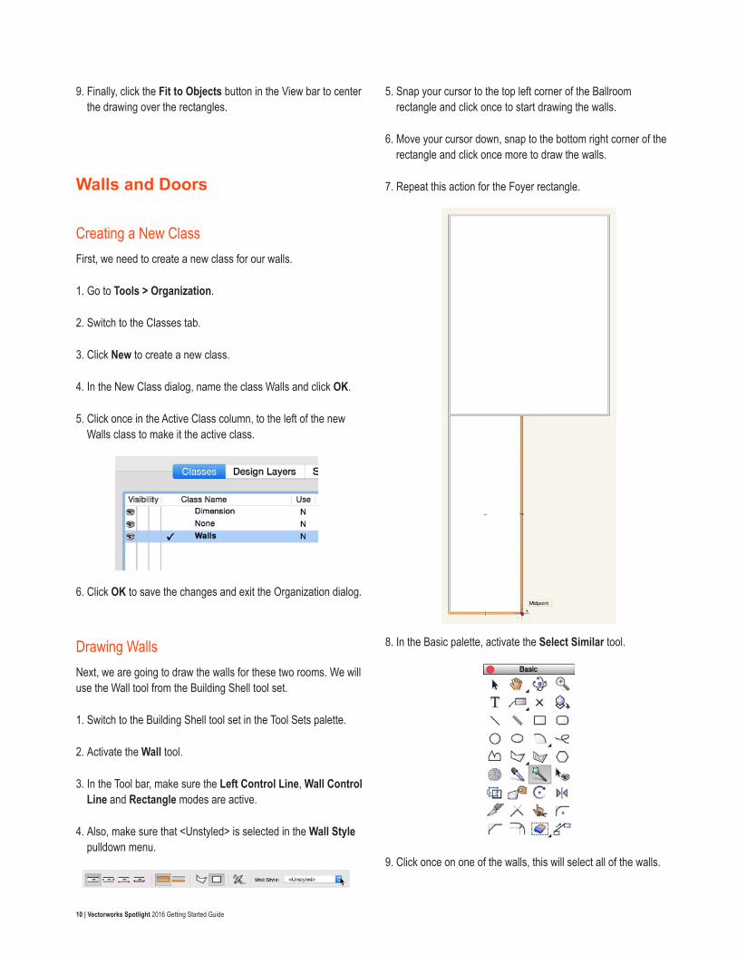
5. Snap your cursor to the top left corner of the Ballroom rectangle and click once to start drawing the walls.
6. Move your cursor down, snap to the bottom right corner of the rectangle and click once more to draw the walls.
7. Repeat this action for the Foyer rectangle.
8. In the Basic palette, activate the Select Similar tool.
9. Click once on one of the walls, this will select all of the walls.
11 | Vectorworks Spotlight 2016 Getting Started Guide
10. In the Object Info palette, set the Height to 20’0” [6.10m] and press Enter.
11. Now, press the X key on your keyboard to activate the Selection tool in the Basic palette and select and delete both of the rectangles.
Placing DoorsNow, we are going to place the doors for these rooms. We will use the imported Image as reference. First, we will need to make the Scan design layer visible.
1. In the Navigation palette, make sure the Design Layers tab is active and click once in the left Visibility column for the Scan design layer to make it visible.
2. In the Building Shell tool set, activate the Door tool.
3. Move your cursor to the top right corner of the Paris Ballroom and center it over the first door location.
4. When your cursor is over top of the wall, you see the wall highlight in red. This indicates that you can insert a door into the wall. Click once to set the insertion point on the door.
5. As you move your cursor, you will see the position of the door swing change. Move your cursor up and to the left and click once to set the position of the swing.
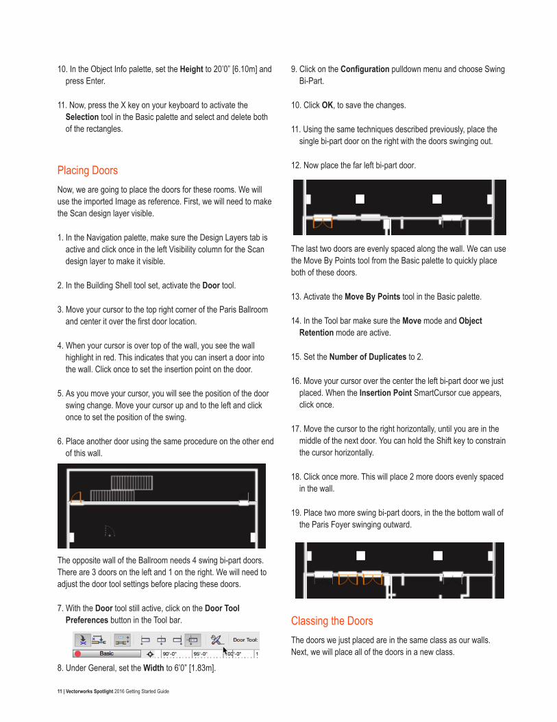
6. Place another door using the same procedure on the other end of this wall.
The opposite wall of the Ballroom needs 4 swing bi-part doors. There are 3 doors on the left and 1 on the right. We will need to adjust the door tool settings before placing these doors.
7. With the Door tool still active, click on the Door Tool Preferences button in the Tool bar.
8. Under General, set the Width to 6’0” [1.83m].
9. Click on the Configuration pulldown menu and choose Swing Bi-Part.
10. Click OK, to save the changes.
11. Using the same techniques described previously, place the single bi-part door on the right with the doors swinging out.
12. Now place the far left bi-part door.
The last two doors are evenly spaced along the wall. We can use the Move By Points tool from the Basic palette to quickly place both of these doors.
13. Activate the Move By Points tool in the Basic palette.
14. In the Tool bar make sure the Move mode and Object Retention mode are active.
15. Set the Number of Duplicates to 2.
16. Move your cursor over the center the left bi-part door we just placed. When the Insertion Point SmartCursor cue appears, click once.
17. Move the cursor to the right horizontally, until you are in the middle of the next door. You can hold the Shift key to constrain the cursor horizontally.
18. Click once more. This will place 2 more doors evenly spaced in the wall.
19. Place two more swing bi-part doors, in the the bottom wall of the Paris Foyer swinging outward.
Classing the DoorsThe doors we just placed are in the same class as our walls. Next, we will place all of the doors in a new class.
12 | Vectorworks Spotlight 2016 Getting Started Guide
1. Activate the Select Similar tool in the Basic palette.
2. Click once, on one of the doors. Confirm the Object Info palette indicates 8 Door Objects In Walls are selected.
3. Then in the Object Info palette, click on the Classes pulldown menu and choose New Class.
4. In the New Class dialog, name the class Doors and click OK.
Let’s take a look at the doors in 3D.
5. In the View bar, click on the Current View menu and choose Right Isometric.
6. Dismiss the Did you know message dialog, by clicking OK.
7. Also, in the View bar, click on the Render Mode menu and choose OpenGL.
You may have noticed, it is hard to see the doors in the walls. This because they are closed by default, in 3D. Let’s set a 3D open angle for these doors.
8. Activate the Select Similar tool in the Basic palette.
9. Click on one of the doors, to select all of the doors.
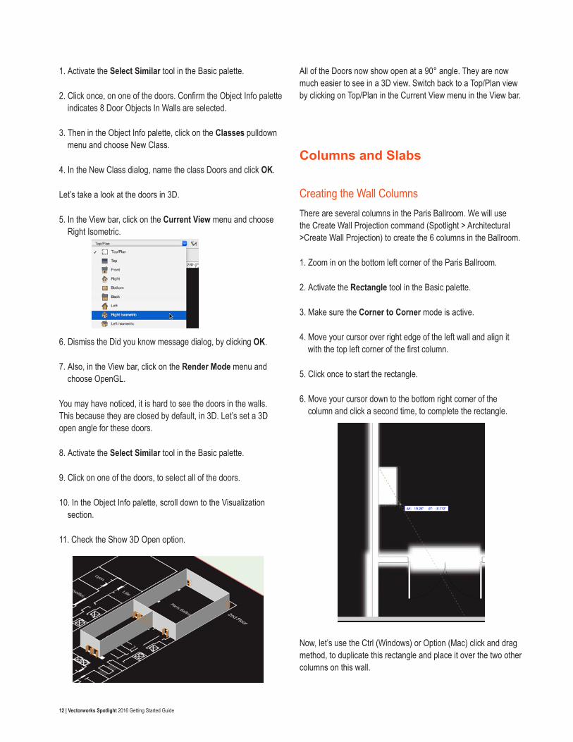
10. In the Object Info palette, scroll down to the Visualization section.
11. Check the Show 3D Open option.
All of the Doors now show open at a 90° angle. They are now much easier to see in a 3D view. Switch back to a Top/Plan view by clicking on Top/Plan in the Current View menu in the View bar.
Columns and Slabs
Creating the Wall ColumnsThere are several columns in the Paris Ballroom. We will use the Create Wall Projection command (Spotlight > Architectural >Create Wall Projection) to create the 6 columns in the Ballroom.
1. Zoom in on the bottom left corner of the Paris Ballroom.
2. Activate the Rectangle tool in the Basic palette.
3. Make sure the Corner to Corner mode is active.
4. Move your cursor over right edge of the left wall and align it with the top left corner of the first column.
5. Click once to start the rectangle.
6. Move your cursor down to the bottom right corner of the column and click a second time, to complete the rectangle.
Now, let’s use the Ctrl (Windows) or Option (Mac) click and drag method, to duplicate this rectangle and place it over the two other columns on this wall.
13 | Vectorworks Spotlight 2016 Getting Started Guide
7. Activate the Selection tool in the Basic palette and enable the Disabled Interactive Scaling mode in the Tool bar.
8. Click Yes, to confirm the mode change. This will disable the blue reshape handles and allow us to more easily move the rectangle without reshaping the rectangle.
9. Move your cursor over the top left corner of the rectangle. Click and drag the rectangle up to the next column.
10. Align the rectangle with right edge of the wall and the top left of the column.
11. Before releasing the mouse button to place the rectangle, press and hold the Ctrl key (Windows) or the Option key (Mac). You will see a small plus sign appear above the cursor. This indicates, that we are going to place a copy of the rectangle.
12. Release the mouse button and then release the Ctrl (Windows) / Option (Mac) key to place a duplicate of the rectangle.
You will want to confirm that the rectangle was copied and not just moved. You should have two rectangles, one over the bottom left column and one over the middle left column.
13. Repeat this action for the last column on this wall.
14. With the Section tool still active, re-enable the Single Object Interactive Scaling mode in the Tool bar.
Next, we will use the Mirror tool from the Basic palette to duplicate these three rectangles to the opposite Wall.
15. With the Selection tool still active, hold the Shift key and select all three rectangles.
16. Activate the Mirror tool in the Basic palette and enable the Duplicate mode in the tool Bar.
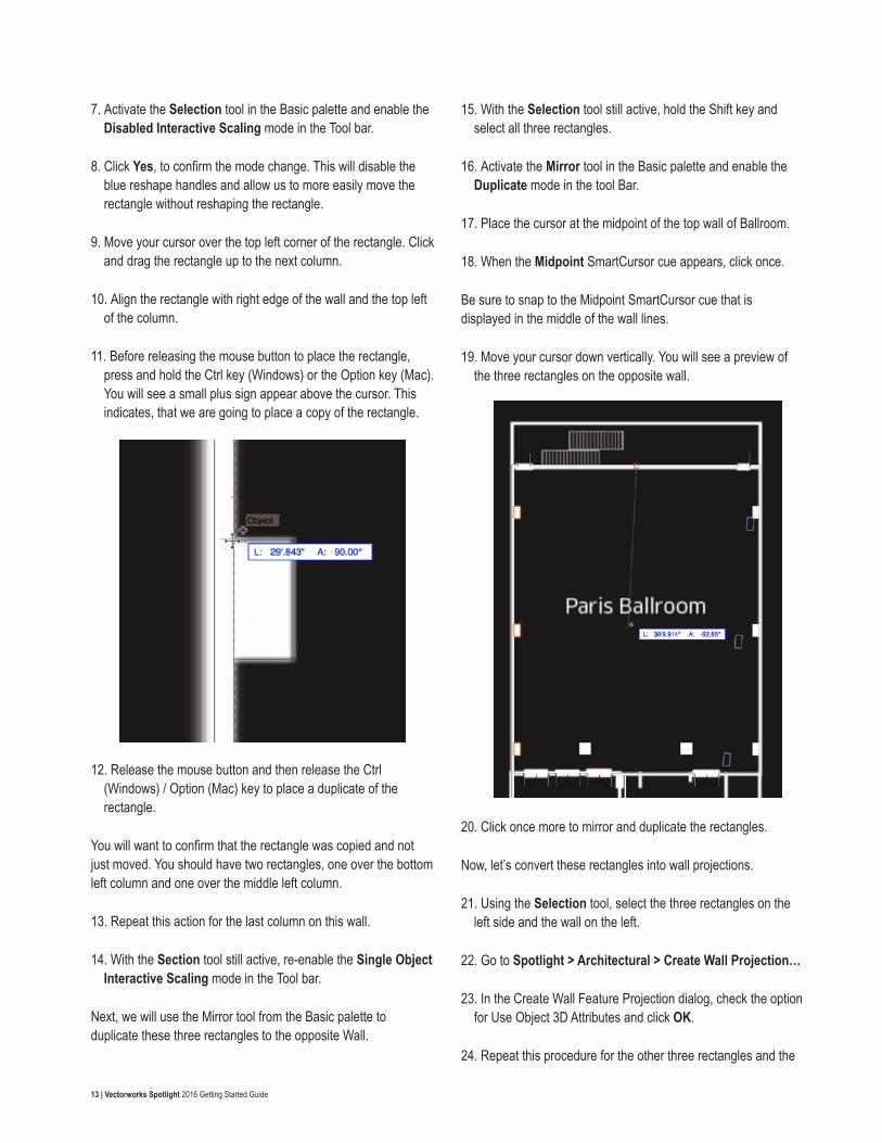
17. Place the cursor at the midpoint of the top wall of Ballroom.
18. When the Midpoint SmartCursor cue appears, click once.
Be sure to snap to the Midpoint SmartCursor cue that is displayed in the middle of the wall lines.
19. Move your cursor down vertically. You will see a preview of the three rectangles on the opposite wall.
20. Click once more to mirror and duplicate the rectangles.
Now, let’s convert these rectangles into wall projections.
21. Using the Selection tool, select the three rectangles on the left side and the wall on the left.
22. Go to Spotlight > Architectural > Create Wall Projection…
23. In the Create Wall Feature Projection dialog, check the option for Use Object 3D Attributes and click OK.
24. Repeat this procedure for the other three rectangles and the
14 | Vectorworks Spotlight 2016 Getting Started Guide
wall on the right.
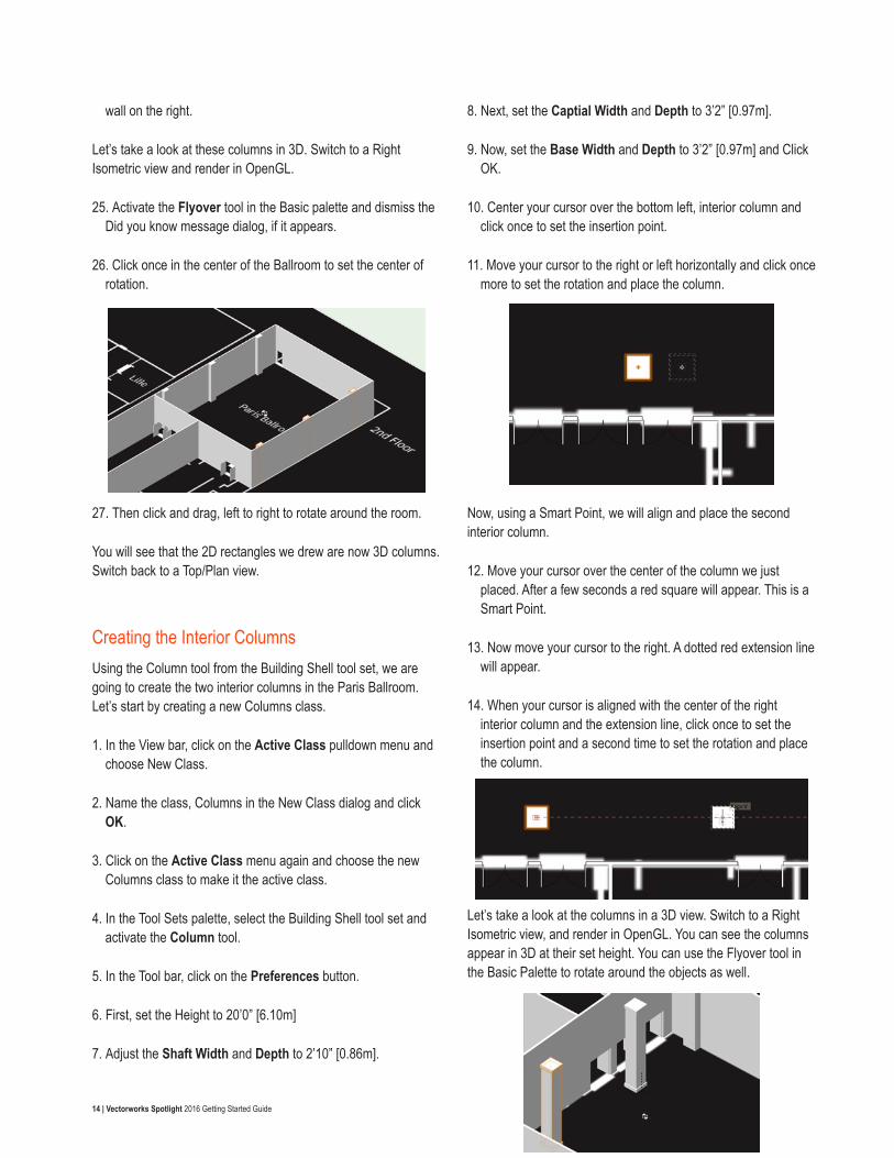
Let’s take a look at these columns in 3D. Switch to a Right Isometric view and render in OpenGL.
25. Activate the Flyover tool in the Basic palette and dismiss the Did you know message dialog, if it appears.
26. Click once in the center of the Ballroom to set the center of rotation.
27. Then click and drag, left to right to rotate around the room.
You will see that the 2D rectangles we drew are now 3D columns. Switch back to a Top/Plan view.
Creating the Interior ColumnsUsing the Column tool from the Building Shell tool set, we are going to create the two interior columns in the Paris Ballroom. Let’s start by creating a new Columns class.
1. In the View bar, click on the Active Class pulldown menu and choose New Class.
2. Name the class, Columns in the New Class dialog and click OK.
3. Click on the Active Class menu again and choose the new Columns class to make it the active class.
4. In the Tool Sets palette, select the Building Shell tool set and activate the Column tool.
5. In the Tool bar, click on the Preferences button.
6. First, set the Height to 20’0” [6.10m]
7. Adjust the Shaft Width and Depth to 2’10” [0.86m].
8. Next, set the Captial Width and Depth to 3’2” [0.97m].
9. Now, set the Base Width and Depth to 3’2” [0.97m] and Click OK.
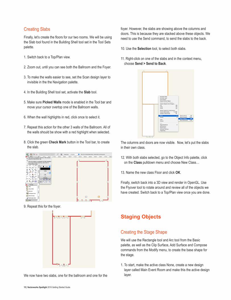
10. Center your cursor over the bottom left, interior column and click once to set the insertion point.
11. Move your cursor to the right or left horizontally and click once more to set the rotation and place the column.
Now, using a Smart Point, we will align and place the second interior column.
12. Move your cursor over the center of the column we just placed. After a few seconds a red square will appear. This is a Smart Point.
13. Now move your cursor to the right. A dotted red extension line will appear.
14. When your cursor is aligned with the center of the right interior column and the extension line, click once to set the insertion point and a second time to set the rotation and place the column.
Let’s take a look at the columns in a 3D view. Switch to a Right Isometric view, and render in OpenGL. You can see the columns appear in 3D at their set height. You can use the Flyover tool in the Basic Palette to rotate around the objects as well.
15 | Vectorworks Spotlight 2016 Getting Started Guide
Creating SlabsFinally, let’s create the floors for our two rooms. We will be using the Slab tool found in the Building Shell tool set in the Tool Sets palette.
1. Switch back to a Top/Plan view.
2. Zoom out, until you can see both the Ballroom and the Foyer.
3. To make the walls easier to see, set the Scan design layer to invisible in the the Navigation palette.
4. In the Building Shell tool set, activate the Slab tool.
5. Make sure Picked Walls mode is enabled in the Tool bar and move your cursor overtop one of the Ballroom walls.
6. When the wall highlights in red, click once to select it.
7. Repeat this action for the other 3 walls of the Ballroom. All of the walls should be show with a red highlight when selected.
8. Click the green Check Mark button in the Tool bar, to create the slab.
9. Repeat this for the foyer.
We now have two slabs, one for the ballroom and one for the
foyer. However, the slabs are showing above the columns and doors. This is because they are stacked above these objects. We need to use the Send command, to send the slabs to the back.
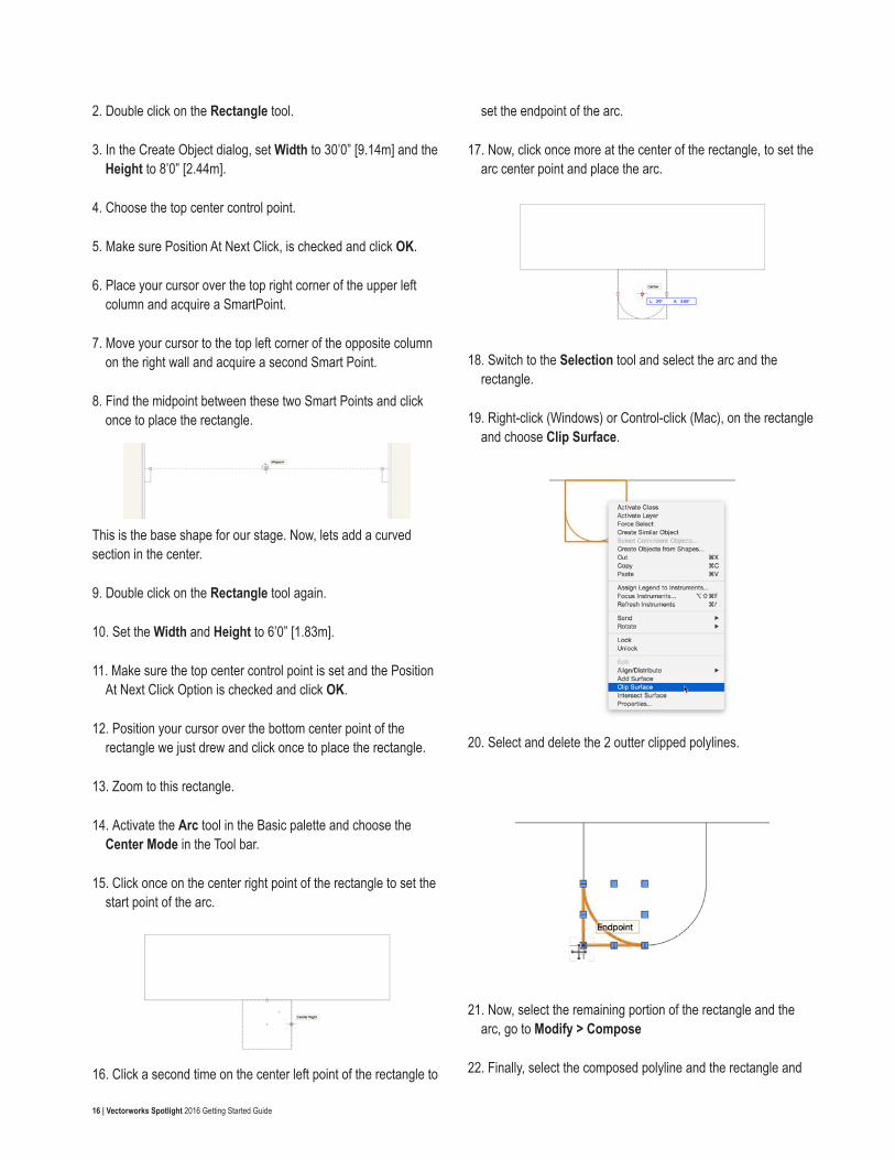
10. Use the Selection tool, to select both slabs.
11. Right-click on one of the slabs and in the context menu, choose Send > Send to Back.
The columns and doors are now visible. Now, let’s put the slabs in their own class.
12. With both slabs selected, go to the Object Info palette, click on the Class pulldown menu and choose New Class…
13. Name the new class Floor and click OK.
Finally, switch back into a 3D view and render in OpenGL. Use the Flyover tool to rotate around and review all of the objects we have created. Switch back to a Top/Plan view once you are done.
Staging Objects
Creating the Stage ShapeWe will use the Rectangle tool and Arc tool from the Basic palette, as well as the Clip Surface, Add Surface and Compose commands from the Modify menu, to create the base shape for the stage.
1. To start, make the active class None, create a new design layer called Main Event Room and make this the active design layer.
16 | Vectorworks Spotlight 2016 Getting Started Guide
2. Double click on the Rectangle tool.
3. In the Create Object dialog, set Width to 30’0” [9.14m] and the Height to 8’0” [2.44m].
4. Choose the top center control point.
5. Make sure Position At Next Click, is checked and click OK.
6. Place your cursor over the top right corner of the upper left column and acquire a SmartPoint.
7. Move your cursor to the top left corner of the opposite column on the right wall and acquire a second Smart Point.
8. Find the midpoint between these two Smart Points and click once to place the rectangle.
This is the base shape for our stage. Now, lets add a curved section in the center.
9. Double click on the Rectangle tool again.
10. Set the Width and Height to 6’0” [1.83m].
11. Make sure the top center control point is set and the Position At Next Click Option is checked and click OK.
12. Position your cursor over the bottom center point of the rectangle we just drew and click once to place the rectangle.
13. Zoom to this rectangle.
14. Activate the Arc tool in the Basic palette and choose the Center Mode in the Tool bar.
15. Click once on the center right point of the rectangle to set the start point of the arc.
16. Click a second time on the center left point of the rectangle to
set the endpoint of the arc.
17. Now, click once more at the center of the rectangle, to set the arc center point and place the arc.
18. Switch to the Selection tool and select the arc and the rectangle.
19. Right-click (Windows) or Control-click (Mac), on the rectangle and choose Clip Surface.
20. Select and delete the 2 outter clipped polylines.
21. Now, select the remaining portion of the rectangle and the arc, go to Modify > Compose
22. Finally, select the composed polyline and the rectangle and
17 | Vectorworks Spotlight 2016 Getting Started Guide
go to Modify > Add Surface.
Creating Stage ObjectsNow, we will convert the base polyline into stage deck and stage plug objects, using the Create Stage… command in the Event Design menu.
1. With the polyline selected, go to Event Design > Create Stage…
2. In the Create Stage dialog, set the Stage Height to 2’0” [0.61m]
3. Set the Standard Stage Deck Width to 8’0” [2.44m]
4. Set the Standard Stage Deck Depth to 6’0” [1.83m].
5. For Object Class, choose New from the pulldown menu and name the class Stage.
6. Click OK twice.
The polyline will be converted into five stage decks and one stage plug. Now, let’s adjust some structural settings for the stage.
7. Switch to a Right Isometric view and zoom in on the stage objects.
8. Select the center curved stage plug.
9. In the Object Info palette, click on the Structure pulldown menu and choose Legs Basic.
10. Under Leg Details, click on the Profile pulldown menu.
11. Choose Octagonal.
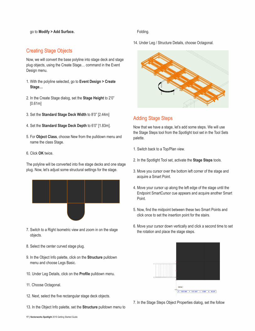
12. Next, select the five rectangular stage deck objects.
13. In the Object Info palette, set the Structure pulldown menu to
Folding.
14. Under Leg / Structure Details, choose Octagonal.
Adding Stage StepsNow that we have a stage, let’s add some steps. We will use the Stage Steps tool from the Spotlight tool set in the Tool Sets palette.
1. Switch back to a Top/Plan view.
2. In the Spotlight Tool set, activate the Stage Steps tools.
3. Move you cursor over the bottom left corner of the stage and acquire a Smart Point.
4. Move your cursor up along the left edge of the stage until the Endpoint SmartCursor cue appears and acquire another Smart Point.
5. Now, find the midpoint between these two Smart Points and click once to set the insertion point for the stairs.
6. Move your cursor down vertically and click a second time to set the rotation and place the stage steps.
7. In the Stage Steps Object Properties dialog, set the follow
18 | Vectorworks Spotlight 2016 Getting Started Guide
parameters:
• Stage Height =2’0” [0.61m]
• Step Unit Width = 4’0” [1.22m]
• Stringer Length = 6’0” [1.83m]
• Stringer Width = 1 ½” [38.1mm]
• Number of Steps = 4
• Step Thickness = 1” [25.4mm]
• Single Step Depth = 1’6” [0.46m]
8. Click OK.
9. With the stage steps still selected, activate the Mirror tool in the Basic palette.
10. Make sure the Duplicate mode is active.
11. Click once on the center of the stage and move the cursor vertically.
12. Click a second time to mirror and duplicate the steps on the other side of the stage.
Applying Attributes and TexturesNext, we are going to apply a fill color to our stage and steps, using the Attributes palette.
1. Select all of the stage decks, stage plug and stage steps.
2. In the Attributes palette, click on the Fill Color box.
3. At the bottom of the Color palette set, choose Standard Vectorworks Colors.
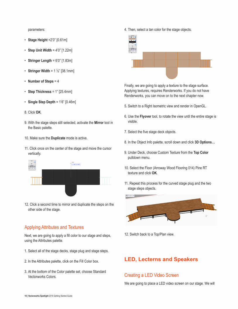
4. Then, select a tan color for the stage objects.
Finally, we are going to apply a texture to the stage surface. Applying textures, requires Renderworks. If you do not have Renderworks, you can move on to the next chapter now.
5. Switch to a Right Isometric view and render in OpenGL.
6. Use the Flyover tool, to rotate the view until the entire stage is visible.
7. Select the five stage deck objects.
8. In the Object Info palette, scroll down and click 3D Options…
9. Under Deck, choose Custom Texture from the Top Color pulldown menu.
10. Select the Floor (Arroway Wood Flooring 014) Pine RT texture and click OK.
11. Repeat this process for the curved stage plug and the two stage steps objects.
12. Switch back to a Top/Plan view.
LED, Lecterns and Speakers
Creating a LED Video ScreenWe are going to place a LED video screen on our stage. We will
19 | Vectorworks Spotlight 2016 Getting Started Guide
use the Video Screen tool from the Spotlight tool set.
1. In the Spotlight tool set, activate the Video Screen tool.
2. Click on the Preferences button in the Tool bar.
3. For Screen Type, choose LED.
4. Set the Screen Aspect to Rect. all custom dimensions.
5. Next, set the Height to 9’0”[2.74m] and the Width to 30’0” [9.14m] and click OK.
6. Zoom in on the stage.
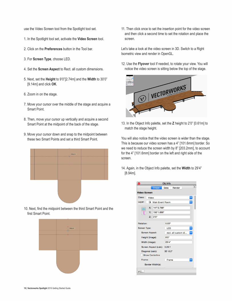
7. Move your cursor over the middle of the stage and acquire a Smart Point.
8. Then, move your cursor up vertically and acquire a second Smart Point at the midpoint of the back of the stage.
9. Move your cursor down and snap to the midpoint between these two Smart Points and set a third Smart Point.
10. Next, find the midpoint between the third Smart Point and the first Smart Point.
11. Then click once to set the insertion point for the video screen and then click a second time to set the rotation and place the screen.
Let’s take a look at the video screen in 3D. Switch to a Right Isometric view and render in OpenGL.
12. Use the Flyover tool if needed, to rotate your view. You will notice the video screen is sitting below the top of the stage.
13. In the Object Info palette, set the Z height to 2’0” [0.61m] to match the stage height.
You will also notice that the video screen is wider than the stage. This is because our video screen has a 4” [101.6mm] border. So we need to reduce the screen width by 8” [203.2mm], to account for the 4” [101.6mm] border on the left and right side of the screen.
14. Again, in the Object Info palette, set the Width to 29’4” [8.94m].
20 | Vectorworks Spotlight 2016 Getting Started Guide
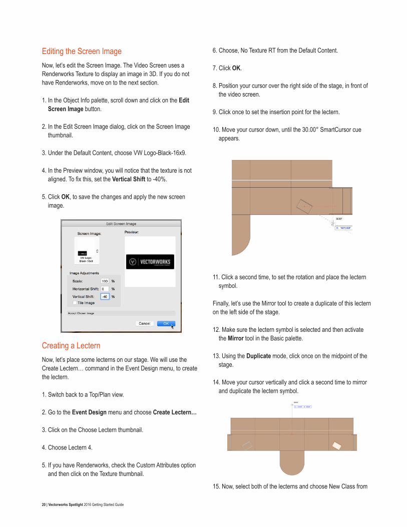
Editing the Screen ImageNow, let’s edit the Screen Image. The Video Screen uses a Renderworks Texture to display an image in 3D. If you do not have Renderworks, move on to the next section.
1. In the Object Info palette, scroll down and click on the Edit Screen Image button.
2. In the Edit Screen Image dialog, click on the Screen Image thumbnail.
3. Under the Default Content, choose VW Logo-Black-16x9.
4. In the Preview window, you will notice that the texture is not aligned. To fix this, set the Vertical Shift to -40%.
5. Click OK, to save the changes and apply the new screen image.
Creating a LecternNow, let’s place some lecterns on our stage. We will use the Create Lectern… command in the Event Design menu, to create the lectern.
1. Switch back to a Top/Plan view.
2. Go to the Event Design menu and choose Create Lectern…
3. Click on the Choose Lectern thumbnail.
4. Choose Lectern 4.
5. If you have Renderworks, check the Custom Attributes option and then click on the Texture thumbnail.
6. Choose, No Texture RT from the Default Content.
7. Click OK.
8. Position your cursor over the right side of the stage, in front of the video screen.
9. Click once to set the insertion point for the lectern.
10. Move your cursor down, until the 30.00° SmartCursor cue appears.
11. Click a second time, to set the rotation and place the lectern symbol.
Finally, let’s use the Mirror tool to create a duplicate of this lectern on the left side of the stage.
12. Make sure the lectern symbol is selected and then activate the Mirror tool in the Basic palette.
13. Using the Duplicate mode, click once on the midpoint of the stage.
14. Move your cursor vertically and click a second time to mirror and duplicate the lectern symbol.
15. Now, select both of the lecterns and choose New Class from
21 | Vectorworks Spotlight 2016 Getting Started Guide
the Class pulldown menu in the Object Info palette.
16. Name the class Lecterns.
SpeakersNext, we will place speakers on the left and right side of the stage. We will use the peaker tool from the Spotlight tool set.
1. Activate the Speaker tool in the Spotlight tool set.
2. Click on the Preferences button in the Tool bar.
3. Under Type, choose Yamaha C112v.
4. For Support, choose Tripod.
5. Set the Stand Height to 4’0” [1.22m] and click OK.
6. Move your cursor between the right wall and the stage, toward the back of the stage.
7. Click once to set the insertion point for the speaker.
8. Move your cursor to the right, horizontally, and click a second time to set the rotation and place the speaker.
Now, let’s angle the speaker in towards the center of the room and place a second speaker on the opposite side of the stage.
9. In the Object Info palette, set the Rotation to -15°.
10. Using the Mirror tool again, create another speaker on the other side of the stage.
Finally, let’s take a look at the objects in 3D. Switch to a Right Isometric view and render in OpenGL. Use the Flyover tool again, to rotate around the Room. Return to a Top/Plan view when you are finished.
Soft Goods
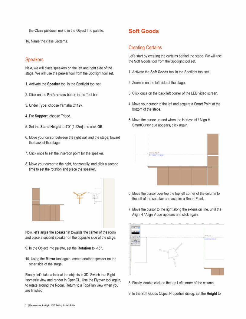
Creating CertainsLet’s start by creating the curtains behind the stage. We will use the Soft Goods tool from the Spotlight tool set.
1. Activate the Soft Goods tool in the Spotlight tool set.
2. Zoom in on the left side of the stage.
3. Click once on the back left corner of the LED video screen.
4. Move your cursor to the left and acquire a Smart Point at the bottom of the steps.
5. Move the cursor up and when the Horizontal / Align H SmartCursor cue appears, click again.
6. Move the cursor over top the top left corner of the column to the left of the speaker and acquire a Smart Point.
7. Move the cursor to the right along the extension line, until the Align H / Align V cue appears and click again.
8. Finally, double click on the top Left corner of the column.
9. In the Soft Goods Object Properties dialog, set the Height to
22 | Vectorworks Spotlight 2016 Getting Started Guide
19’0” [5.79m].
10. Check the Add Track option and click OK.
We now have a curtain on the left side of the stage. Use the Mirror tool to create a duplicate on the other side of the stage.
11. Activate the Soft Goods tool again.
12. Move your cursor to left side of the stage, above the left edge of the LED video screen.
13. Press the Z key on your keyboard to activate the Snap Loupe.
14. Align your cursor with the center of the soft goods object where it meets the screen.
15. When the Insertion Point cue appears, click once.
16. Move your cursor to the right side of the stage and using the Snap Loupe (Z) again, position the cursor over the insertion point of the other curtain.
17. Double click to place the curtain.
Let’s take a look at the curtains in 3D. Switch to a Left Isometric view and render in OpenGL. We need to adjust the height of the Curtain behind LED video screen.
18. With the curtain behind the screen selected go to the Object Info palette and set the Height to 7’6” [2.29m].
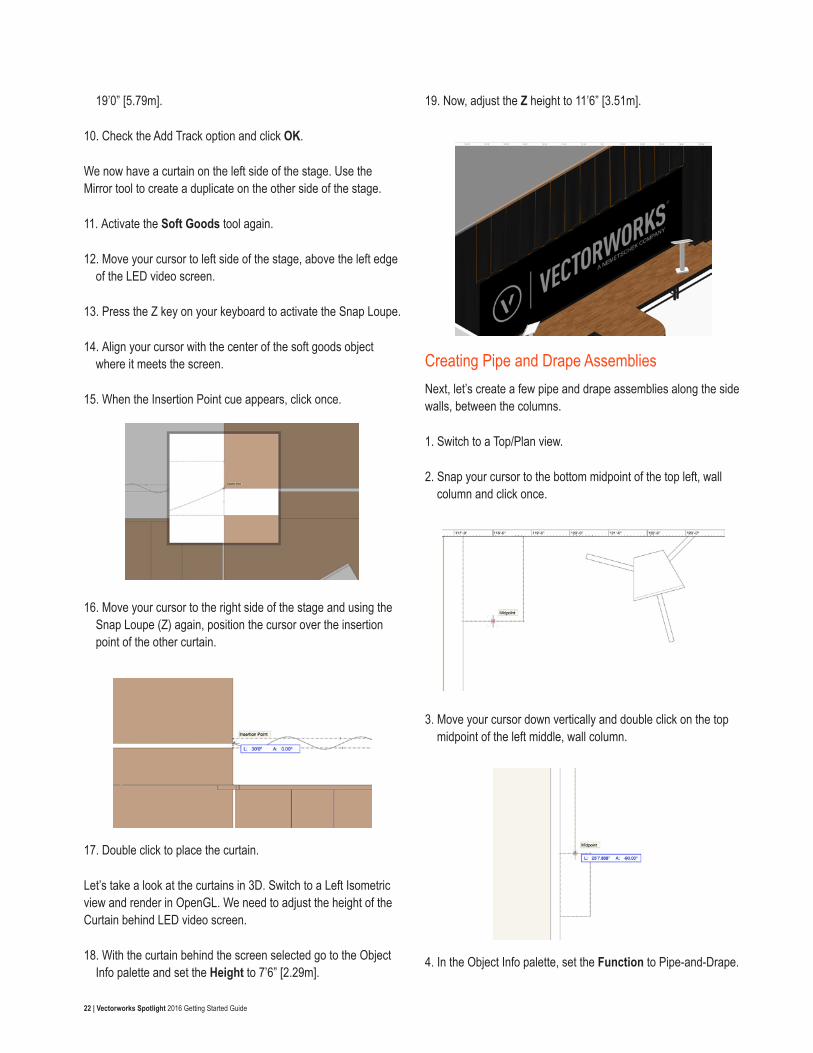
19. Now, adjust the Z height to 11’6” [3.51m].
Creating Pipe and Drape AssembliesNext, let’s create a few pipe and drape assemblies along the side walls, between the columns.
1. Switch to a Top/Plan view.
2. Snap your cursor to the bottom midpoint of the top left, wall column and click once.
3. Move your cursor down vertically and double click on the top midpoint of the left middle, wall column.
4. In the Object Info palette, set the Function to Pipe-and-Drape.
23 | Vectorworks Spotlight 2016 Getting Started Guide
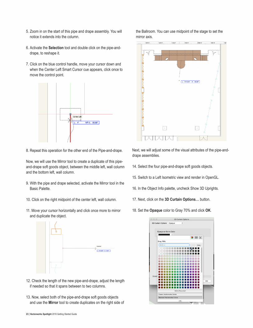
5. Zoom in on the start of this pipe and drape assembly. You will notice it extends into the column.
6. Activate the Selection tool and double click on the pipe-and-drape, to reshape it.
7. Click on the blue control handle, move your cursor down and when the Center Left Smart Cursor cue appears, click once to move the control point.
8. Repeat this operation for the other end of the Pipe-and-drape.
Now, we will use the Mirror tool to create a duplicate of this pipe-and-drape soft goods object, between the middle left, wall column and the bottom left, wall column.
9. With the pipe and drape selected, activate the Mirror tool in the Basic Palette.
10. Click on the right midpoint of the center left, wall column.
11. Move your cursor horizontally and click once more to mirror and duplicate the object.
12. Check the length of the new pipe-and-drape, adjust the length if needed so that it spans between to two columns.
13. Now, select both of the pipe-and-drape soft goods objects and use the Mirror tool to create duplicates on the right side of
the Ballroom. You can use midpoint of the stage to set the mirror axis.
Next, we will adjust some of the visual attributes of the pipe-and-drape assemblies.
14. Select the four pipe-and-drape soft goods objects.
15. Switch to a Left Isometric view and render in OpenGL.
16. In the Object Info palette, uncheck Show 3D Uprights.
17. Next, click on the 3D Curtain Options… button.
18. Set the Opaque color to Gray 70% and click OK.
24 | Vectorworks Spotlight 2016 Getting Started Guide
19. Use the Flyover tool to review the changes and then switch back to a Top/Plan view.
Creating a BorderFinally, we will create a border around the front of the stage.
1. Activate the Soft Goods tool again and zoom in on the left corner of thesStage.
2. Use the Snap Loupe (Z) to zoom in even farther, on the corner of the stage.
3. When the Top Left SmartCursor cue appears, click once to start the border.
4. Move your cursor along the front edge of the stage and click a second time at the corner of the curved stage plug and stage deck.
5. Now, move your cursor down, along the left side of the curved stage plug. When the Arc SmartCursor cue appears click again.
To create the curved portion of the path for the border, we need to change the vertex mode of the Soft Goods tool.
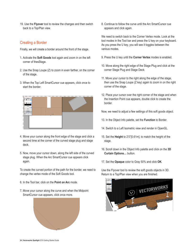
6. In the Tool bar, click on the Point on Arc mode.
7. Move your cursor along the curve and when the Midpoint SmartCursor cue appears, click once more.
8. Continue to follow the curve until the Arc SmartCursor cue appears and click again.
We need to switch back to the Corner Vertex mode. Look at the tool modes in the Tool bar and press the U key on your keyboard. As you press the U key, you will see it toggles between the various modes.
9. Press the U key until the Corner Vertex modes is enabled.
10. Move along the right edge of the Stage Plug and click at the corner Stage Plug and Stage Deck.
11. Move your cursor to the right along the edge of the stage, then use the Snap Loupe (Z key) again to zoom in on the right corner of the stage.
12. Place your cursor over the right corner of the stage and when the Insertion Point cue appears, double click to create the border.
Now, we need to adjust a few settings of this soft goods object.
13. In the Object Info palette, set the Function to Border.
14. Switch to a Left Isometric view and render in OpenGL.
15. Set the Height to 2’0”[0.61m], to match the height of the stage.
16. Scroll down in the Object Info palette and click on the 3D Curtain Options… button.
17. Set the Opaque color to Gray 50% and click OK.
Use the Flyover tool to review the soft goods objects in 3D. Return to a Top/Plan view when you are finished.
25 | Vectorworks Spotlight 2016 Getting Started Guide
Seating Layouts
Creating the Presentation SeatingLet’s start by creating the presentation seating. We will use the Create Objects from Shapes command, to convert a base rectangle into a seating layout.
1. Double click on the Rectangle tool in the Basic palette.
2. Set the Width to 47’0” [14.33m] and the Height to 36’0” [10.97m].
3. Make sure the top center control point is set and the Position At Next Click option is enabled and click OK.
4. Zoom in on the front of the stage and place your cursor over the bottom midpoint of the curved stag plug.
5. When the Midpoint SmartCursor cue appears, press the G key to create a datum point.
We will use this datum point as reference
6. Press the Tab key to activate the Floating Data bar.
7. Continue to press Tab to cycle through the fields in the Floating Data bar.
8. In the Length (L) field, enter 6’0” [1.83m] and press Tab again to set the value.
9. Move your cursor down along the vertical, green extension line, until the Length / Align H cue appears.
10. Click once to place the rectangle.
11. With the rectangle selected, go to the Modify menu and choose Create Objects from Shapes…
12. In the Create Objects from Shapes dialog, set the Object Type to Seating Layout.
13. Make sure Show Properties Dialog is checked and the Delete Source Shapes option is unchecked and click OK.
14. In the Object Properties dialog, enable the Concentric option and click OK.
15. A seating count worksheet will appear. Close the worksheet window.
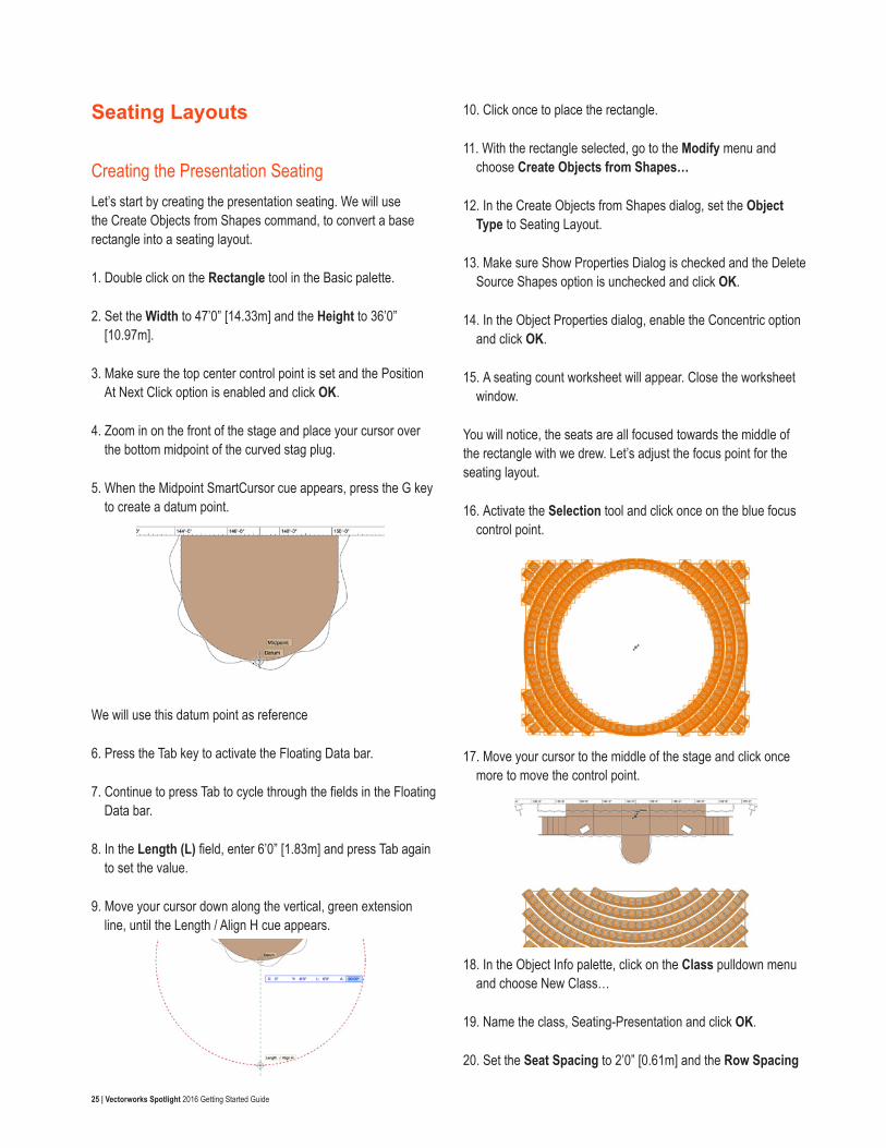
You will notice, the seats are all focused towards the middle of the rectangle with we drew. Let’s adjust the focus point for the seating layout.
16. Activate the Selection tool and click once on the blue focus control point.
17. Move your cursor to the middle of the stage and click once more to move the control point.
18. In the Object Info palette, click on the Class pulldown menu and choose New Class…
19. Name the class, Seating-Presentation and click OK.
20. Set the Seat Spacing to 2’0” [0.61m] and the Row Spacing
26 | Vectorworks Spotlight 2016 Getting Started Guide
to 3’0” [0.91m]
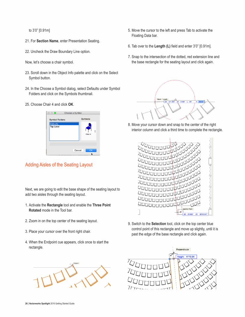
21. For Section Name, enter Presentation Seating.
22. Uncheck the Draw Boundary Line option.
Now, let’s choose a chair symbol.
23. Scroll down in the Object Info palette and click on the Select Symbol button.
24. In the Choose a Symbol dialog, select Defaults under Symbol Folders and click on the Symbols thumbnail.
25. Choose Chair 4 and click OK.
Adding Aisles of the Seating Layout
Next, we are going to edit the base shape of the seating layout to add two aisles through the seating layout.
1. Activate the Rectangle tool and enable the Three Point Rotated mode in the Tool bar.
2. Zoom in on the top center of the seating layout.
3. Place your cursor over the front right chair.
4. When the Endpoint cue appears, click once to start the rectangle.
5. Move the cursor to the left and press Tab to activate the Floating Data bar.
6. Tab over to the Length (L) field and enter 3’0” [0.91m].
7. Snap to the intersection of the dotted, red extension line and the base rectangle for the seating layout and click again.
8. Move your cursor down and snap to the center of the right interior column and click a third time to complete the rectangle.
9. Switch to the Selection tool, click on the top center blue control point of this rectangle and move up slightly, until it is past the edge of the base rectangle and click again.
27 | Vectorworks Spotlight 2016 Getting Started Guide
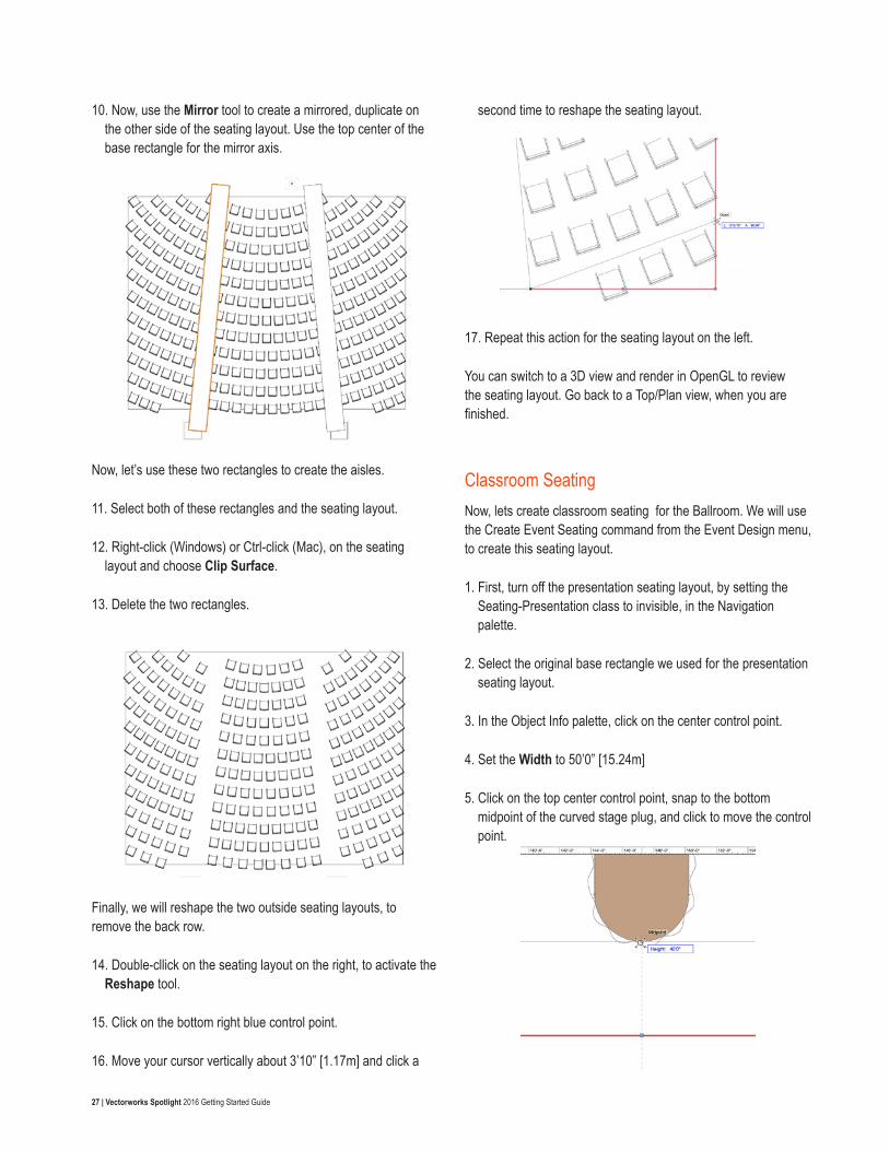
10. Now, use the Mirror tool to create a mirrored, duplicate on the other side of the seating layout. Use the top center of the base rectangle for the mirror axis.
Now, let’s use these two rectangles to create the aisles.
11. Select both of these rectangles and the seating layout.
12. Right-click (Windows) or Ctrl-click (Mac), on the seating layout and choose Clip Surface.
13. Delete the two rectangles.
Finally, we will reshape the two outside seating layouts, to remove the back row.
14. Double-cllick on the seating layout on the right, to activate the Reshape tool.
15. Click on the bottom right blue control point.
16. Move your cursor vertically about 3’10” [1.17m] and click a
second time to reshape the seating layout.
17. Repeat this action for the seating layout on the left.
You can switch to a 3D view and render in OpenGL to review the seating layout. Go back to a Top/Plan view, when you are finished.
Classroom SeatingNow, lets create classroom seating for the Ballroom. We will use the Create Event Seating command from the Event Design menu, to create this seating layout.
1. First, turn off the presentation seating layout, by setting the Seating-Presentation class to invisible, in the Navigation palette.
2. Select the original base rectangle we used for the presentation seating layout.
3. In the Object Info palette, click on the center control point.
4. Set the Width to 50’0” [15.24m]
5. Click on the top center control point, snap to the bottom midpoint of the curved stage plug, and click to move the control point.
28 | Vectorworks Spotlight 2016 Getting Started Guide
6. Now, click on the bottom center control point, snap to the top corner of one of the interior columns, and click a second time to move the control point.
7. With the rectangle selected, go to Event Design > Create Event Seating…
8. Under Seating Arrangement, choose Classroom.
9. Set the Seat Spacing to 6’0” [1.83m] and the Row Spacing to 7’0” [2.13m].
10. Name the Seating Section, Classroom Seating.
11. Click on the Seating Symbol thumbnail and choose the Table 6’x2.5’ and Chairs-2 symbol.
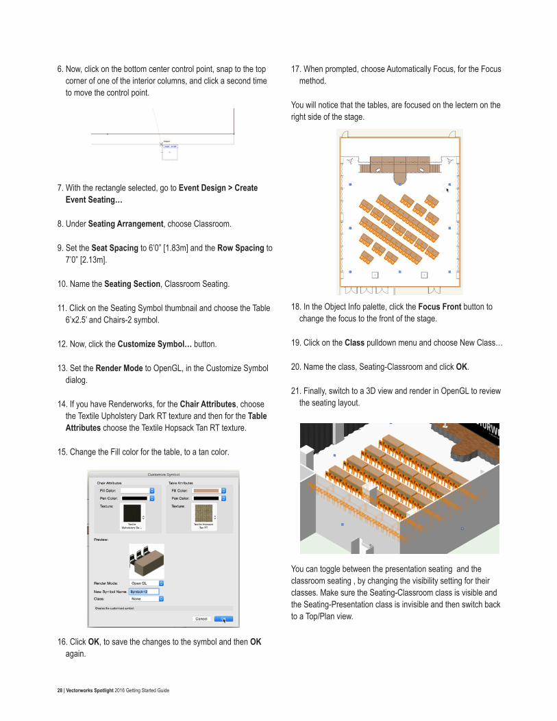
12. Now, click the Customize Symbol… button.
13. Set the Render Mode to OpenGL, in the Customize Symbol dialog.
14. If you have Renderworks, for the Chair Attributes, choose the Textile Upholstery Dark RT texture and then for the Table Attributes choose the Textile Hopsack Tan RT texture.
15. Change the Fill color for the table, to a tan color.
16. Click OK, to save the changes to the symbol and then OK again.
17. When prompted, choose Automatically Focus, for the Focus method.
You will notice that the tables, are focused on the lectern on the right side of the stage.
18. In the Object Info palette, click the Focus Front button to change the focus to the front of the stage.
19. Click on the Class pulldown menu and choose New Class…
20. Name the class, Seating-Classroom and click OK.
21. Finally, switch to a 3D view and render in OpenGL to review the seating layout.
You can toggle between the presentation seating and the classroom seating , by changing the visibility setting for their classes. Make sure the Seating-Classroom class is visible and the Seating-Presentation class is invisible and then switch back to a Top/Plan view.
29 | Vectorworks Spotlight 2016 Getting Started Guide
Lighting Position, Lighting Devices and Label Legend
Creating a Lighting PipeLet’s start by using the Lighting Pipe tool from the Spotlight tool set, to create the geometry for our lighting position.
1. Go to Tools > Organization.
2. Click on the Design Layers tab.
3. Click New.
4. Name the new design layer, Light Plot and click OK.
5. Click OK again.
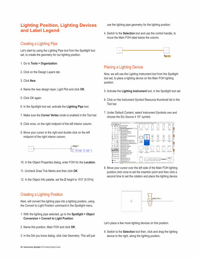
6. In the Spotlight tool set, activate the Lighting Pipe tool.
7. Make sure the Corner Vertex mode is enabled in the Tool bar.
8. Click once, on the right midpoint of the left interior column.
9. Move your cursor to the right and double click on the left midpoint of the right interior column.
10. In the Object Properties dialog, enter FOH for the Location.
11. Uncheck Draw Tick Marks and then click OK.
12. In the Object Info palette, set the Z height to 15’0” [4.57m].
Creating a Lighting PositionNext, will convert the lighting pipe into a lighting position, using the Convert to Light Position command in the Spotlight menu.
1. With the lighting pipe selected, go to the Spotlight > Object Conversion > Convert to Light Position.
2. Name this position, Main FOH and click OK.
3. In the Did you know dialog, click Use Geometry. This will just
use the lighting pipe geometry for the lighting position.
4. Switch to the Selection tool and use the control handle, to move the Main FOH label below the column.
Placing a Lighting DeviceNow, we will use the Lighting Instrument tool from the Spotlight tool set, to place a lighting device on the Main FOH lighting position.
5. Activate the Lighting Instrument tool, in the Spotlight tool set.
6. Click on the Instrument Symbol Resource thumbnail list in the Tool bar.
7. Under Default Content, select Instrument Symbols.vwx and choose the Etc Source 4 19° symbol.
8. Move your cursor over the left side of the Main FOH lighting position,click once to set the insertion point and then click a second time to set the rotation and place the lighting device.
Let’s place a few more lighting devices on this position.
9. Switch to the Selection tool then, click and drag the lighting device to the right, along the lighting position.
30 | Vectorworks Spotlight 2016 Getting Started Guide
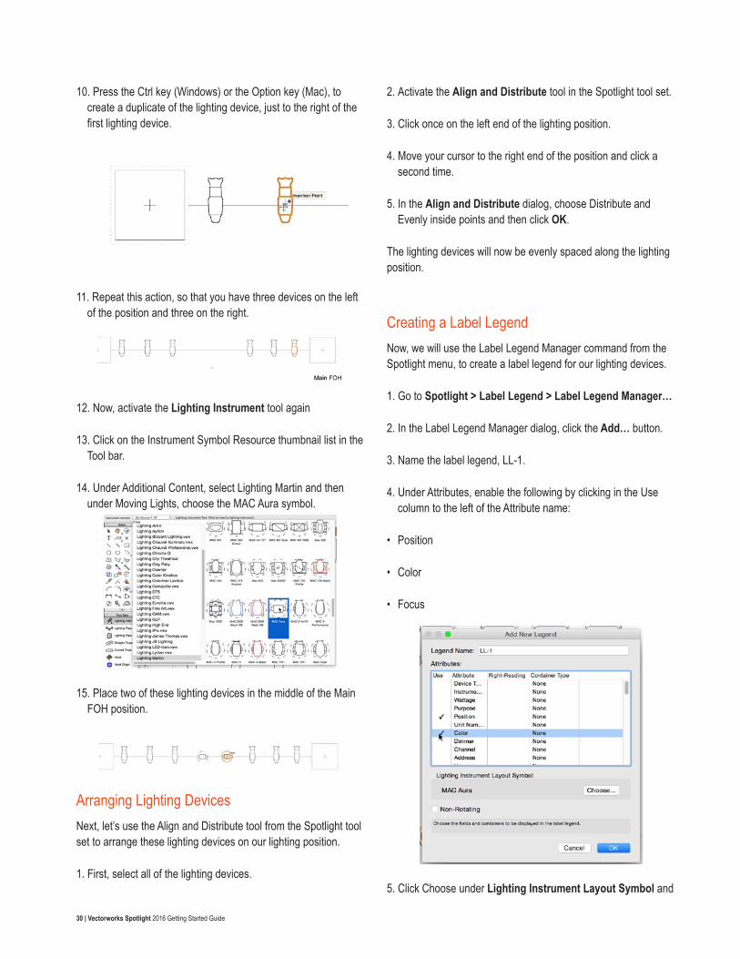
10. Press the Ctrl key (Windows) or the Option key (Mac), to create a duplicate of the lighting device, just to the right of the first lighting device.
11. Repeat this action, so that you have three devices on the left of the position and three on the right.
12. Now, activate the Lighting Instrument tool again
13. Click on the Instrument Symbol Resource thumbnail list in the Tool bar.
14. Under Additional Content, select Lighting Martin and then under Moving Lights, choose the MAC Aura symbol.
15. Place two of these lighting devices in the middle of the Main FOH position.
Arranging Lighting DevicesNext, let’s use the Align and Distribute tool from the Spotlight tool set to arrange these lighting devices on our lighting position.
1. First, select all of the lighting devices.
2. Activate the Align and Distribute tool in the Spotlight tool set.
3. Click once on the left end of the lighting position.
4. Move your cursor to the right end of the position and click a second time.
5. In the Align and Distribute dialog, choose Distribute and Evenly inside points and then click OK.
The lighting devices will now be evenly spaced along the lighting position.
Creating a Label LegendNow, we will use the Label Legend Manager command from the Spotlight menu, to create a label legend for our lighting devices.
1. Go to Spotlight > Label Legend > Label Legend Manager…
2. In the Label Legend Manager dialog, click the Add… button.
3. Name the label legend, LL-1.
4. Under Attributes, enable the following by clicking in the Use column to the left of the Attribute name:
• Position
• Color
• Focus
5. Click Choose under Lighting Instrument Layout Symbol and
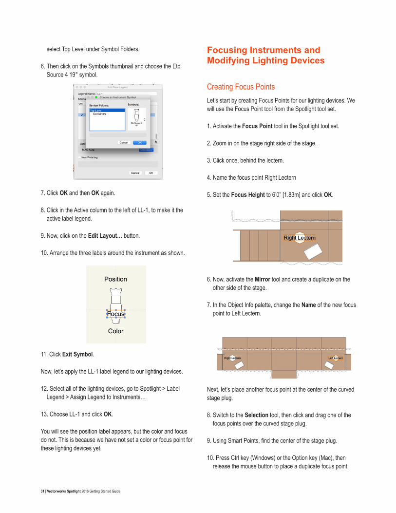
31 | Vectorworks Spotlight 2016 Getting Started Guide
select Top Level under Symbol Folders.
6. Then click on the Symbols thumbnail and choose the Etc Source 4 19° symbol.
7. Click OK and then OK again.
8. Click in the Active column to the left of LL-1, to make it the active label legend.
9. Now, click on the Edit Layout… button.
10. Arrange the three labels around the instrument as shown.
11. Click Exit Symbol.
Now, let’s apply the LL-1 label legend to our lighting devices.
12. Select all of the lighting devices, go to Spotlight > Label Legend > Assign Legend to Instruments…
13. Choose LL-1 and click OK.
You will see the position label appears, but the color and focus do not. This is because we have not set a color or focus point for these lighting devices yet.
Focusing Instruments and Modifying Lighting Devices
Creating Focus PointsLet’s start by creating Focus Points for our lighting devices. We will use the Focus Point tool from the Spotlight tool set.
1. Activate the Focus Point tool in the Spotlight tool set.
2. Zoom in on the stage right side of the stage.
3. Click once, behind the lectern.
4. Name the focus point Right Lectern
5. Set the Focus Height to 6’0” [1.83m] and click OK.
6. Now, activate the Mirror tool and create a duplicate on the other side of the stage.
7. In the Object Info palette, change the Name of the new focus point to Left Lectern.
Next, let’s place another focus point at the center of the curved stage plug.
8. Switch to the Selection tool, then click and drag one of the focus points over the curved stage plug.
9. Using Smart Points, find the center of the stage plug.
10. Press Ctrl key (Windows) or the Option key (Mac), then release the mouse button to place a duplicate focus point.
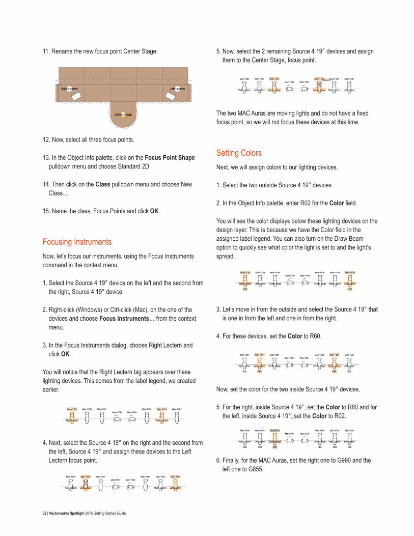
32 | Vectorworks Spotlight 2016 Getting Started Guide
11. Rename the new focus point Center Stage.
12. Now, select all three focus points.
13. In the Object Info palette, click on the Focus Point Shape pulldown menu and choose Standard 2D.
14. Then click on the Class pulldown menu and choose New Class…
15. Name the class, Focus Points and click OK.
Focusing InstrumentsNow, let’s focus our instruments, using the Focus Instruments command in the context menu.
1. Select the Source 4 19° device on the left and the second from the right, Source 4 19° device.
2. Right-click (Windows) or Ctrl-click (Mac), on the one of the devices and choose Focus Instruments… from the context menu.
3. In the Focus Instruments dialog, choose Right Lectern and click OK.
You will notice that the Right Lectern tag appears over these lighting devices. This comes from the label legend, we created earlier.
4. Next, select the Source 4 19° on the right and the second from the left, Source 4 19° and assign these devices to the Left Lectern focus point.
5. Now, select the 2 remaining Source 4 19° devices and assign them to the Center Stage, focus point.
The two MAC Auras are moving lights and do not have a fixed focus point, so we will not focus these devices at this time.
Setting Colors Next, we will assign colors to our lighting devices.
1. Select the two outside Source 4 19° devices.
2. In the Object Info palette, enter R02 for the Color field.
You will see the color displays below these lighting devices on the design layer. This is because we have the Color field in the assigned label legend. You can also turn on the Draw Beam option to quickly see what color the light is set to and the light’s spread.
3. Let’s move in from the outside and select the Source 4 19° that is one in from the left and one in from the right.
4. For these devices, set the Color to R60.
Now, set the color for the two inside Source 4 19° devices.
5. For the right, inside Source 4 19°, set the Color to R60 and for the left, inside Source 4 19°, set the Color to R02.
6. Finally, for the MAC Auras, set the right one to G990 and the left one to G855.
33 | Vectorworks Spotlight 2016 Getting Started Guide
Rendering in 3DNow we are going to render using Renderworks and modify our lighting devices.
1. First, switch to a Right Isometric view and use the Flyover tool to center the view on the stage.
2. Render in Final Quality Renderworks.
You will notice that the light from our lighting devices does not show. This is because we have not turned on the lights yet.
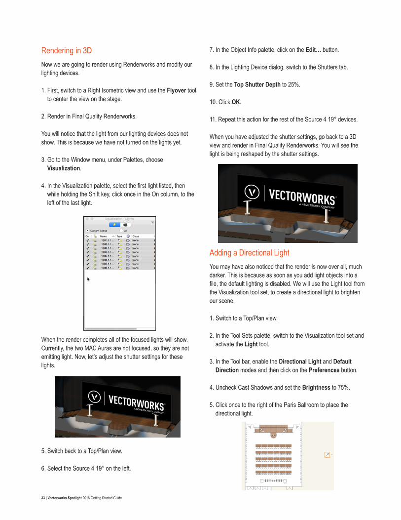
3. Go to the Window menu, under Palettes, choose Visualization.
4. In the Visualization palette, select the first light listed, then while holding the Shift key, click once in the On column, to the left of the last light.
When the render completes all of the focused lights will show. Currently, the two MAC Auras are not focused, so they are not emitting light. Now, let’s adjust the shutter settings for these lights.
5. Switch back to a Top/Plan view.
6. Select the Source 4 19° on the left.
7. In the Object Info palette, click on the Edit… button.
8. In the Lighting Device dialog, switch to the Shutters tab.
9. Set the Top Shutter Depth to 25%.
10. Click OK.
11. Repeat this action for the rest of the Source 4 19° devices.
When you have adjusted the shutter settings, go back to a 3D view and render in Final Quality Renderworks. You will see the light is being reshaped by the shutter settings.
Adding a Directional LightYou may have also noticed that the render is now over all, much darker. This is because as soon as you add light objects into a file, the default lighting is disabled. We will use the Light tool from the Visualization tool set, to create a directional light to brighten our scene.
1. Switch to a Top/Plan view.
2. In the Tool Sets palette, switch to the Visualization tool set and activate the Light tool.
3. In the Tool bar, enable the Directional Light and Default Direction modes and then click on the Preferences button.
4. Uncheck Cast Shadows and set the Brightness to 75%.
5. Click once to the right of the Paris Ballroom to place the directional light.
34 | Vectorworks Spotlight 2016 Getting Started Guide
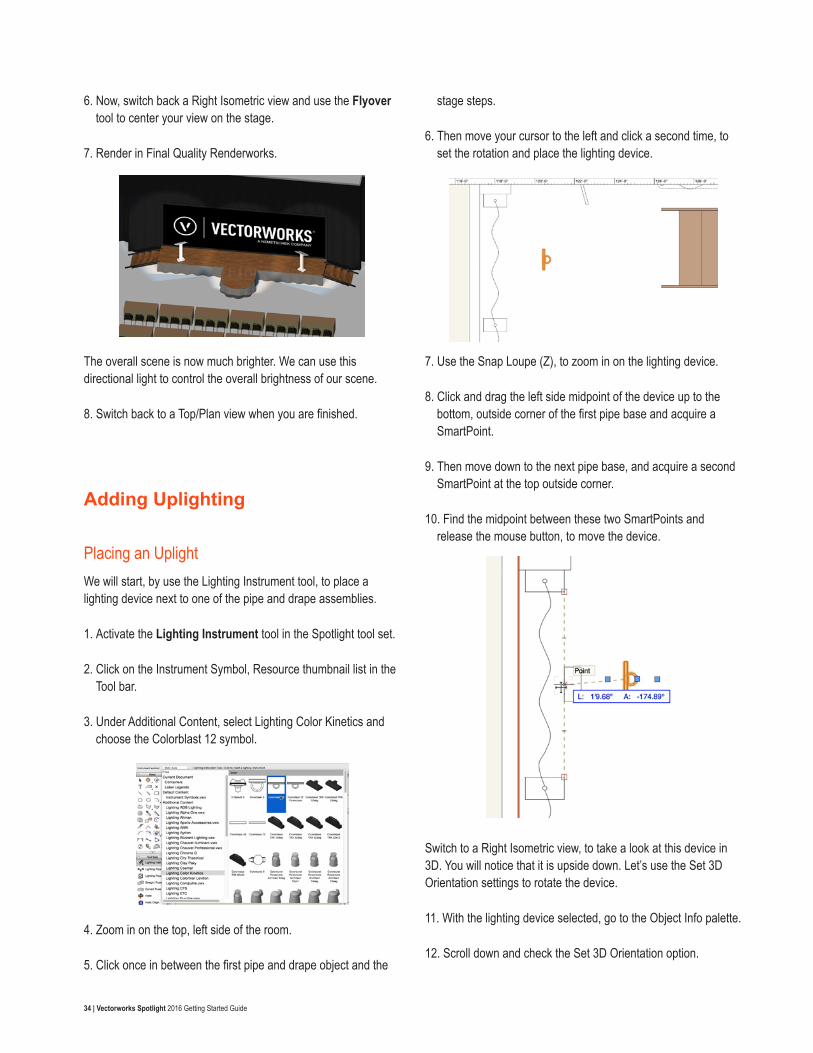
6. Now, switch back a Right Isometric view and use the Flyover tool to center your view on the stage.
7. Render in Final Quality Renderworks.
The overall scene is now much brighter. We can use this directional light to control the overall brightness of our scene.
8. Switch back to a Top/Plan view when you are finished.
Adding Uplighting
Placing an UplightWe will start, by use the Lighting Instrument tool, to place a lighting device next to one of the pipe and drape assemblies.
1. Activate the Lighting Instrument tool in the Spotlight tool set.
2. Click on the Instrument Symbol, Resource thumbnail list in the Tool bar.
3. Under Additional Content, select Lighting Color Kinetics and choose the Colorblast 12 symbol.
4. Zoom in on the top, left side of the room.
5. Click once in between the first pipe and drape object and the
stage steps.
6. Then move your cursor to the left and click a second time, to set the rotation and place the lighting device.
7. Use the Snap Loupe (Z), to zoom in on the lighting device.
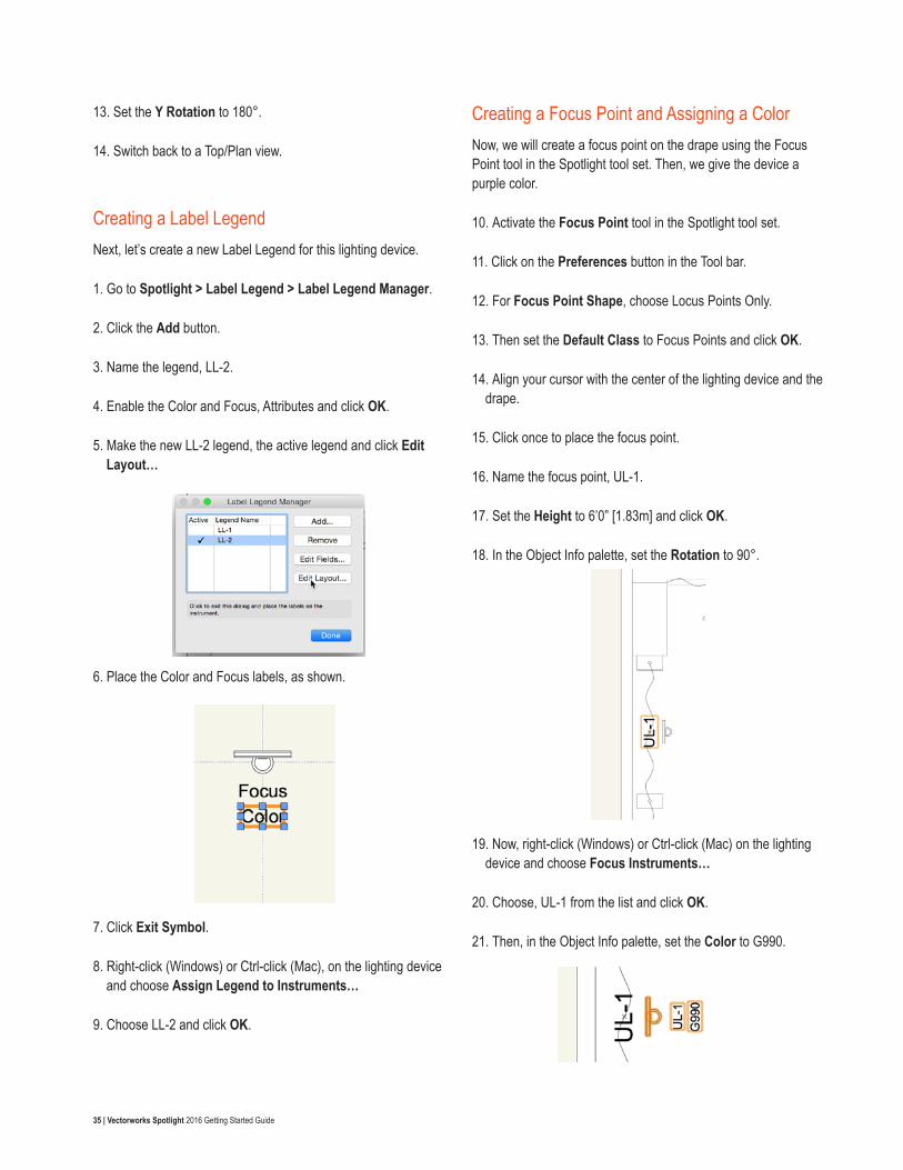
8. Click and drag the left side midpoint of the device up to the bottom, outside corner of the first pipe base and acquire a SmartPoint.
9. Then move down to the next pipe base, and acquire a second SmartPoint at the top outside corner.
10. Find the midpoint between these two SmartPoints and release the mouse button, to move the device.
Switch to a Right Isometric view, to take a look at this device in 3D. You will notice that it is upside down. Let’s use the Set 3D Orientation settings to rotate the device.
11. With the lighting device selected, go to the Object Info palette.
12. Scroll down and check the Set 3D Orientation option.
35 | Vectorworks Spotlight 2016 Getting Started Guide
13. Set the Y Rotation to 180°.
14. Switch back to a Top/Plan view.
Creating a Label LegendNext, let’s create a new Label Legend for this lighting device.
1. Go to Spotlight > Label Legend > Label Legend Manager.
2. Click the Add button.
3. Name the legend, LL-2.
4. Enable the Color and Focus, Attributes and click OK.
5. Make the new LL-2 legend, the active legend and click Edit Layout…
6. Place the Color and Focus labels, as shown.
7. Click Exit Symbol.
8. Right-click (Windows) or Ctrl-click (Mac), on the lighting device and choose Assign Legend to Instruments…
9. Choose LL-2 and click OK.
Creating a Focus Point and Assigning a ColorNow, we will create a focus point on the drape using the Focus Point tool in the Spotlight tool set. Then, we give the device a purple color.
10. Activate the Focus Point tool in the Spotlight tool set.
11. Click on the Preferences button in the Tool bar.
12. For Focus Point Shape, choose Locus Points Only.
13. Then set the Default Class to Focus Points and click OK.
14. Align your cursor with the center of the lighting device and the drape.
15. Click once to place the focus point.
16. Name the focus point, UL-1.
17. Set the Height to 6’0” [1.83m] and click OK.
18. In the Object Info palette, set the Rotation to 90°.
19. Now, right-click (Windows) or Ctrl-click (Mac) on the lighting device and choose Focus Instruments…
20. Choose, UL-1 from the list and click OK.
21. Then, in the Object Info palette, set the Color to G990.
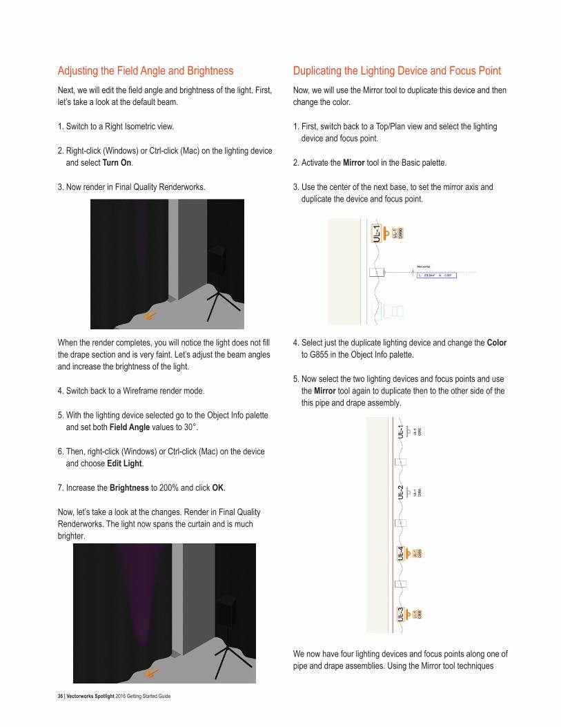
36 | Vectorworks Spotlight 2016 Getting Started Guide
Adjusting the Field Angle and BrightnessNext, we will edit the field angle and brightness of the light. First, let’s take a look at the default beam.
1. Switch to a Right Isometric view.
2. Right-click (Windows) or Ctrl-click (Mac) on the lighting device and select Turn On.
3. Now render in Final Quality Renderworks.
When the render completes, you will notice the light does not fill the drape section and is very faint. Let’s adjust the beam angles and increase the brightness of the light.
4. Switch back to a Wireframe render mode.
5. With the lighting device selected go to the Object Info palette and set both Field Angle values to 30°.
6. Then, right-click (Windows) or Ctrl-click (Mac) on the device and choose Edit Light.
7. Increase the Brightness to 200% and click OK.
Now, let’s take a look at the changes. Render in Final Quality Renderworks. The light now spans the curtain and is much brighter.
Duplicating the Lighting Device and Focus PointNow, we will use the Mirror tool to duplicate this device and then change the color.
1. First, switch back to a Top/Plan view and select the lighting device and focus point.
2. Activate the Mirror tool in the Basic palette.
3. Use the center of the next base, to set the mirror axis and duplicate the device and focus point.
4. Select just the duplicate lighting device and change the Color to G855 in the Object Info palette.
5. Now select the two lighting devices and focus points and use the Mirror tool again to duplicate then to the other side of the this pipe and drape assembly.
We now have four lighting devices and focus points along one of pipe and drape assemblies. Using the Mirror tool techniques
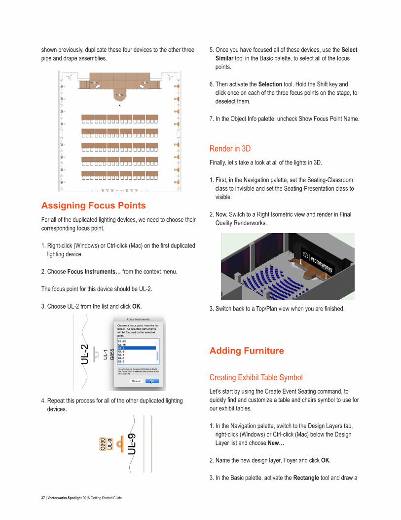
37 | Vectorworks Spotlight 2016 Getting Started Guide
shown previously, duplicate these four devices to the other three pipe and drape assemblies.
Assigning Focus PointsFor all of the duplicated lighting devices, we need to choose their corresponding focus point.
1. Right-click (Windows) or Ctrl-click (Mac) on the first duplicated lighting device.
2. Choose Focus Instruments… from the context menu.
The focus point for this device should be UL-2.
3. Choose UL-2 from the list and click OK.
4. Repeat this process for all of the other duplicated lighting devices.
5. Once you have focused all of these devices, use the Select Similar tool in the Basic palette, to select all of the focus points.
6. Then activate the Selection tool. Hold the Shift key and click once on each of the three focus points on the stage, to deselect them.
7. In the Object Info palette, uncheck Show Focus Point Name.
Render in 3DFinally, let’s take a look at all of the lights in 3D.
1. First, in the Navigation palette, set the Seating-Classroom class to invisible and set the Seating-Presentation class to visible.
2. Now, Switch to a Right Isometric view and render in Final Quality Renderworks.
3. Switch back to a Top/Plan view when you are finished.
Adding Furniture
Creating Exhibit Table SymbolLet’s start by using the Create Event Seating command, to quickly find and customize a table and chairs symbol to use for our exhibit tables.
1. In the Navigation palette, switch to the Design Layers tab, right-click (Windows) or Ctrl-click (Mac) below the Design Layer list and choose New…
2. Name the new design layer, Foyer and click OK.
3. In the Basic palette, activate the Rectangle tool and draw a
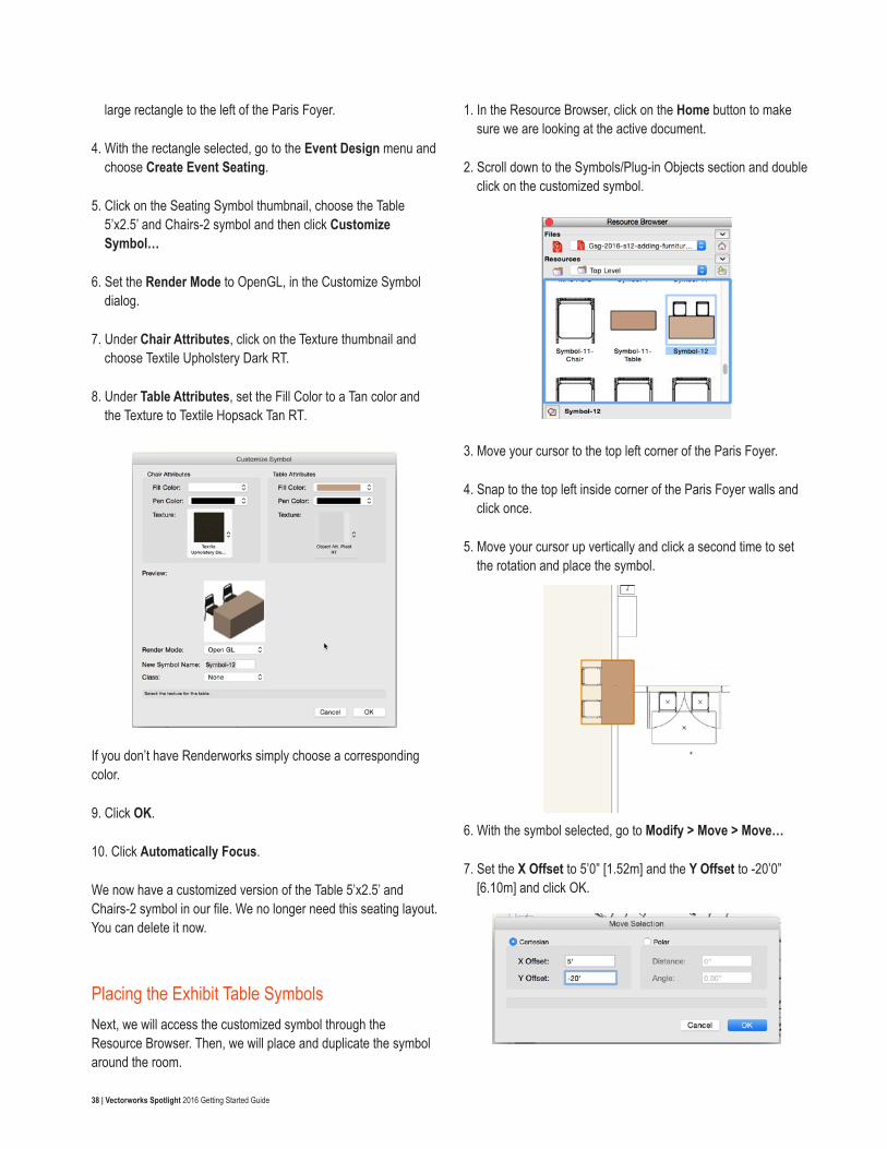
38 | Vectorworks Spotlight 2016 Getting Started Guide
large rectangle to the left of the Paris Foyer.
4. With the rectangle selected, go to the Event Design menu and choose Create Event Seating.
5. Click on the Seating Symbol thumbnail, choose the Table 5’x2.5’ and Chairs-2 symbol and then click Customize Symbol…
6. Set the Render Mode to OpenGL, in the Customize Symbol dialog.
7. Under Chair Attributes, click on the Texture thumbnail and choose Textile Upholstery Dark RT.
8. Under Table Attributes, set the Fill Color to a Tan color and the Texture to Textile Hopsack Tan RT.
If you don’t have Renderworks simply choose a corresponding color.
9. Click OK.
10. Click Automatically Focus.
We now have a customized version of the Table 5’x2.5’ and Chairs-2 symbol in our file. We no longer need this seating layout. You can delete it now.
Placing the Exhibit Table SymbolsNext, we will access the customized symbol through the Resource Browser. Then, we will place and duplicate the symbol around the room.
1. In the Resource Browser, click on the Home button to make sure we are looking at the active document.
2. Scroll down to the Symbols/Plug-in Objects section and double click on the customized symbol.
3. Move your cursor to the top left corner of the Paris Foyer.
4. Snap to the top left inside corner of the Paris Foyer walls and click once.
5. Move your cursor up vertically and click a second time to set the rotation and place the symbol.
6. With the symbol selected, go to Modify > Move > Move…
7. Set the X Offset to 5’0” [1.52m] and the Y Offset to -20’0” [6.10m] and click OK.
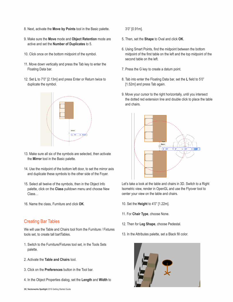
39 | Vectorworks Spotlight 2016 Getting Started Guide
8. Next, activate the Move by Points tool in the Basic palette.
9. Make sure the Move mode and Object Retention mode are active and set the Number of Duplicates to 5.
10. Click once on the bottom midpoint of the symbol.
11. Move down vertically and press the Tab key to enter the Floating Data bar.
12. Set L to 7’0” [2.13m] and press Enter or Return twice to duplicate the symbol.
13. Make sure all six of the symbols are selected, then activate the Mirror tool in the Basic palette.
14. Use the midpoint of the bottom left door, to set the mirror axis and duplicate these symbols to the other side of the Foyer.
15. Select all twelve of the symbols, then in the Object Info palette, click on the Class pulldown menu and choose New Class…
16. Name the class, Furniture and click OK.
Creating Bar TablesWe will use the Table and Chairs tool from the Furniture / Fixtures tools set, to create tall bartTables.
1. Switch to the Furniture/Fixtures tool set, in the Tools Sets palette.
2. Activate the Table and Chairs tool.
3. Click on the Preferences button in the Tool bar.
4. In the Object Properties dialog, set the Length and Width to
3’0” [0.91m].
5. Then, set the Shape to Oval and click OK.
6. Using Smart Points, find the midpoint between the bottom midpoint of the first table on the left and the top midpoint of the second table on the left.
7. Press the G key to create a datum point.
8. Tab into enter the Floating Data bar, set the L field to 5’0” [1.52m] and press Tab again.
9. Move your cursor to the right horizontally, until you intersect the dotted red extension line and double click to place the table and chairs.
Let’s take a look at the table and chairs in 3D. Switch to a Right Isometric view, render in OpenGL and use the Flyover tool to center your view on the table and chairs.
10. Set the Height to 4’0” [1.22m].
11. For Chair Type, choose None.
12. Then for Leg Shape, choose Pedestal.
13. In the Attributes palette, set a Black fill color.
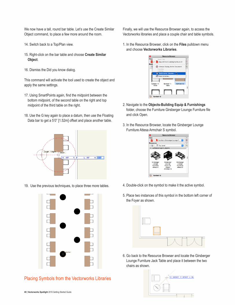
40 | Vectorworks Spotlight 2016 Getting Started Guide
We now have a tall, round bar table. Let’s use the Create Similar Object command, to place a few more around the room.
14. Switch back to a Top/Plan view.
15. Right-click on the bar table and choose Create Similar Object.
16. Dismiss the Did you know dialog.
This command will activate the tool used to create the object and apply the same settings.
17. Using SmartPoints again, find the midpoint between the bottom midpoint, of the second table on the right and top midpoint of the third table on the right.
18. Use the G key again to place a datum, then use the Floating Data bar to get a 5’0” [1.52m] offset and place another table.
19. Use the previous techniques, to place three more tables.
Placing Symbols from the Vectorworks Libraries
Finally, we will use the Resource Browser again, to access the Vectorworks libraries and place a couple chair and table symbols.
1. In the Resource Browser, click on the Files pulldown menu and choose Vectorworks Libraries.
2. Navigate to the Objects-Building Equip & Furnishings folder, choose the Furniture Girsberger Lounge Furniture file and click Open.
3. In the Resource Browser, locate the Girsberger Lounge Furniture Attesa Armchair S symbol.
4. Double-click on the symbol to make it the active symbol.
5. Place two instances of this symbol in the bottom left corner of the Foyer as shown.
6. Go back to the Resource Browser and locate the Girsberger Lounge Furniture Jack Table and place it between the two chairs as shown.
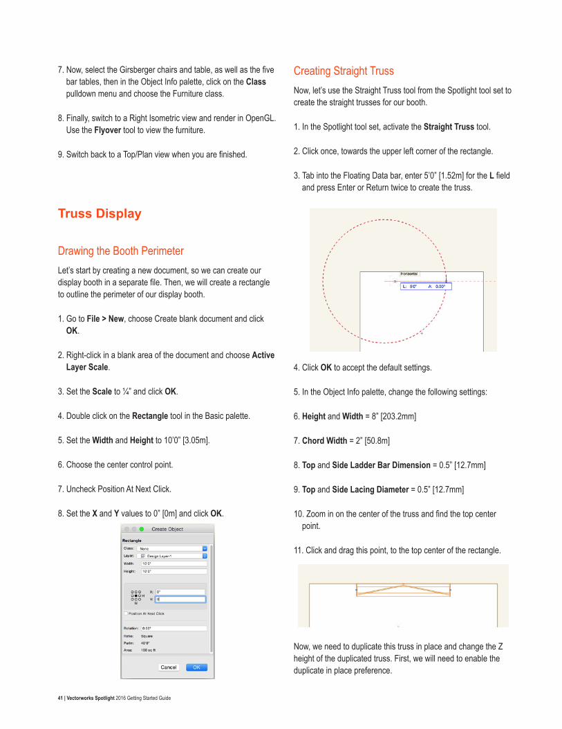
41 | Vectorworks Spotlight 2016 Getting Started Guide
7. Now, select the Girsberger chairs and table, as well as the five bar tables, then in the Object Info palette, click on the Class pulldown menu and choose the Furniture class.
8. Finally, switch to a Right Isometric view and render in OpenGL. Use the Flyover tool to view the furniture.
9. Switch back to a Top/Plan view when you are finished.
Truss Display
Drawing the Booth Perimeter Let’s start by creating a new document, so we can create our display booth in a separate file. Then, we will create a rectangle to outline the perimeter of our display booth.
1. Go to File > New, choose Create blank document and click OK.
2. Right-click in a blank area of the document and choose Active Layer Scale.
3. Set the Scale to ¼” and click OK.
4. Double click on the Rectangle tool in the Basic palette.
5. Set the Width and Height to 10’0” [3.05m].
6. Choose the center control point.
7. Uncheck Position At Next Click.
8. Set the X and Y values to 0” [0m] and click OK.
Creating Straight TrussNow, let’s use the Straight Truss tool from the Spotlight tool set to create the straight trusses for our booth.
1. In the Spotlight tool set, activate the Straight Truss tool.
2. Click once, towards the upper left corner of the rectangle.
3. Tab into the Floating Data bar, enter 5’0” [1.52m] for the L field and press Enter or Return twice to create the truss.
4. Click OK to accept the default settings.
5. In the Object Info palette, change the following settings:
6. Height and Width = 8” [203.2mm]
7. Chord Width = 2” [50.8m]
8. Top and Side Ladder Bar Dimension = 0.5” [12.7mm]
9. Top and Side Lacing Diameter = 0.5” [12.7mm]
10. Zoom in on the center of the truss and find the top center point.
11. Click and drag this point, to the top center of the rectangle.
Now, we need to duplicate this truss in place and change the Z height of the duplicated truss. First, we will need to enable the duplicate in place preference.
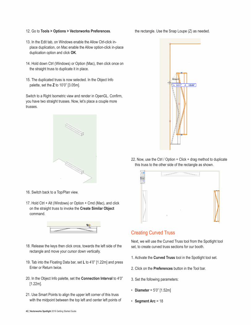
42 | Vectorworks Spotlight 2016 Getting Started Guide
12. Go to Tools > Options > Vectorworks Preferences.
13. In the Edit tab, on Windows enable the Allow Ctrl-click in-place duplication, on Mac enable the Allow option-click in-place duplication option and click OK.
14. Hold down Ctrl (Windows) or Option (Mac), then click once on the straight truss to duplicate it in place.
15. The duplicated truss is now selected. In the Object Info palette, set the Z to 10’0” [3.05m].
Switch to a Right Isometric view and render in OpenGL. Confirm, you have two straight trusses. Now, let’s place a couple more trusses.
16. Switch back to a Top/Plan view.
17. Hold Ctrl + Alt (Windows) or Option + Cmd (Mac), and click on the straight truss to invoke the Create Similar Object command.
18. Release the keys then click once, towards the left side of the rectangle and move your cursor down vertically.
19. Tab into the Floating Data bar, set L to 4’0” [1.22m] and press Enter or Return twice.
20. In the Object Info palette, set the Connection Interval to 4’0” [1.22m].
21. Use Smart Points to align the upper left corner of this truss with the midpoint between the top left and center left points of
the rectangle. Use the Snap Loupe (Z) as needed.
22. Now, use the Ctrl / Option + Click + drag method to duplicate this truss to the other side of the rectangle as shown.
Creating Curved TrussNext, we will use the Curved Truss tool from the Spotlight tool set, to create curved truss sections for our booth.
1. Activate the Curved Truss tool in the Spotlight tool set.
2. Click on the Preferences button in the Tool bar.
3. Set the following parameters:
• Diameter = 5’0” [1.52m]
• Segment Arc = 18
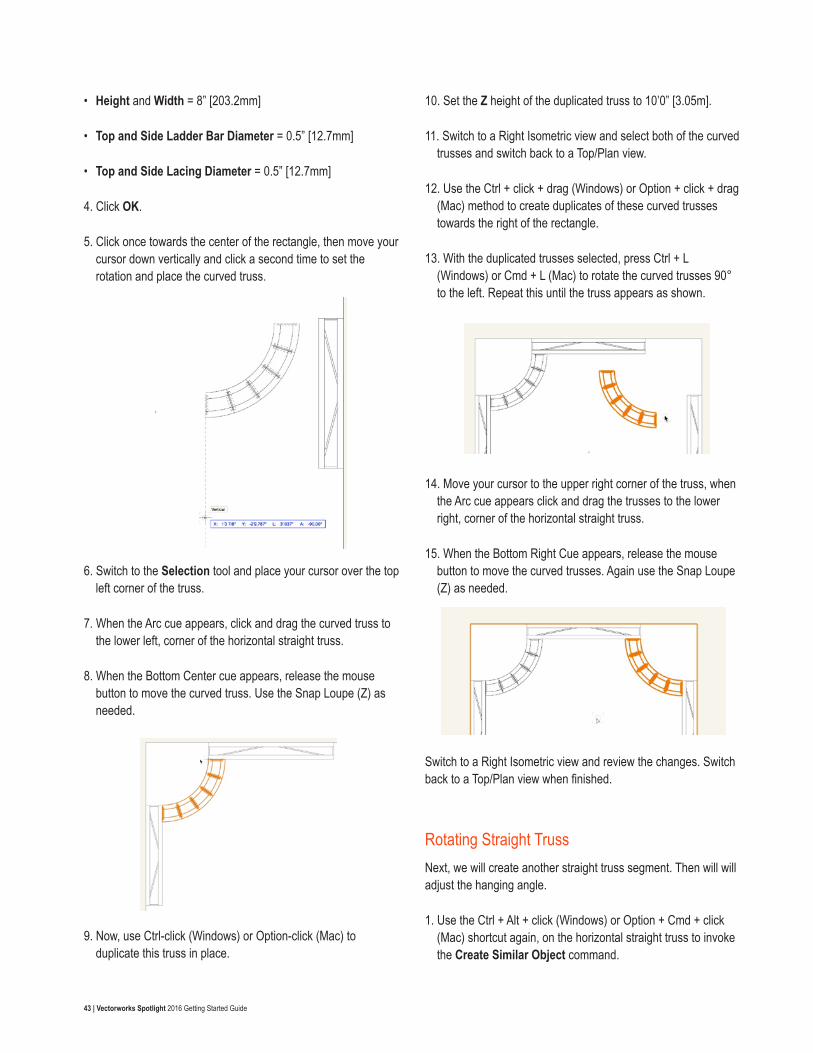
43 | Vectorworks Spotlight 2016 Getting Started Guide
• Height and Width = 8” [203.2mm]
• Top and Side Ladder Bar Diameter = 0.5” [12.7mm]
• Top and Side Lacing Diameter = 0.5” [12.7mm]
4. Click OK.
5. Click once towards the center of the rectangle, then move your cursor down vertically and click a second time to set the rotation and place the curved truss.
6. Switch to the Selection tool and place your cursor over the top left corner of the truss.
7. When the Arc cue appears, click and drag the curved truss to the lower left, corner of the horizontal straight truss.
8. When the Bottom Center cue appears, release the mouse button to move the curved truss. Use the Snap Loupe (Z) as needed.
9. Now, use Ctrl-click (Windows) or Option-click (Mac) to duplicate this truss in place.
10. Set the Z height of the duplicated truss to 10’0” [3.05m].
11. Switch to a Right Isometric view and select both of the curved trusses and switch back to a Top/Plan view.
12. Use the Ctrl + click + drag (Windows) or Option + click + drag (Mac) method to create duplicates of these curved trusses towards the right of the rectangle.
13. With the duplicated trusses selected, press Ctrl + L (Windows) or Cmd + L (Mac) to rotate the curved trusses 90° to the left. Repeat this until the truss appears as shown.
14. Move your cursor to the upper right corner of the truss, when the Arc cue appears click and drag the trusses to the lower right, corner of the horizontal straight truss.
15. When the Bottom Right Cue appears, release the mouse button to move the curved trusses. Again use the Snap Loupe (Z) as needed.
Switch to a Right Isometric view and review the changes. Switch back to a Top/Plan view when finished.
Rotating Straight TrussNext, we will create another straight truss segment. Then will will adjust the hanging angle.
1. Use the Ctrl + Alt + click (Windows) or Option + Cmd + click (Mac) shortcut again, on the horizontal straight truss to invoke the Create Similar Object command.
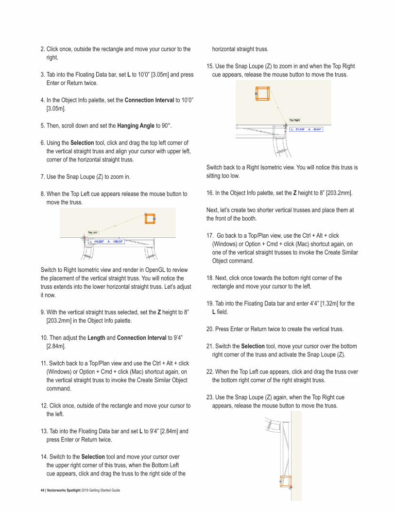
44 | Vectorworks Spotlight 2016 Getting Started Guide
2. Click once, outside the rectangle and move your cursor to the right.
3. Tab into the Floating Data bar, set L to 10’0” [3.05m] and press Enter or Return twice.
4. In the Object Info palette, set the Connection Interval to 10’0” [3.05m].
5. Then, scroll down and set the Hanging Angle to 90°.
6. Using the Selection tool, click and drag the top left corner of the vertical straight truss and align your cursor with upper left, corner of the horizontal straight truss.
7. Use the Snap Loupe (Z) to zoom in.
8. When the Top Left cue appears release the mouse button to move the truss.
Switch to Right Isometric view and render in OpenGL to review the placement of the vertical straight truss. You will notice the truss extends into the lower horizontal straight truss. Let’s adjust it now.
9. With the vertical straight truss selected, set the Z height to 8” [203.2mm] in the Object Info palette.
10. Then adjust the Length and Connection Interval to 9’4” [2.84m].
11. Switch back to a Top/Plan view and use the Ctrl + Alt + click (Windows) or Option + Cmd + click (Mac) shortcut again, on the vertical straight truss to invoke the Create Similar Object command.
12. Click once, outside of the rectangle and move your cursor to the left.
13. Tab into the Floating Data bar and set L to 9’4” [2.84m] and press Enter or Return twice.
14. Switch to the Selection tool and move your cursor over the upper right corner of this truss, when the Bottom Left cue appears, click and drag the truss to the right side of the
horizontal straight truss.
15. Use the Snap Loupe (Z) to zoom in and when the Top Right cue appears, release the mouse button to move the truss.
Switch back to a Right Isometric view. You will notice this truss is sitting too low.
16. In the Object Info palette, set the Z height to 8” [203.2mm].
Next, let’s create two shorter vertical trusses and place them at the front of the booth.
17. Go back to a Top/Plan view, use the Ctrl + Alt + click (Windows) or Option + Cmd + click (Mac) shortcut again, on one of the vertical straight trusses to invoke the Create Similar Object command.
18. Next, click once towards the bottom right corner of the rectangle and move your cursor to the left.
19. Tab into the Floating Data bar and enter 4’4” [1.32m] for the L field.
20. Press Enter or Return twice to create the vertical truss.
21. Switch the Selection tool, move your cursor over the bottom right corner of the truss and activate the Snap Loupe (Z).
22. When the Top Left cue appears, click and drag the truss over the bottom right corner of the right straight truss.
23. Use the Snap Loupe (Z) again, when the Top Right cue appears, release the mouse button to move the truss.
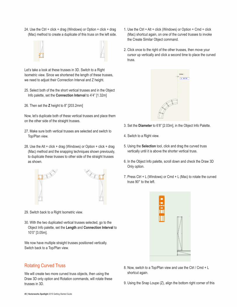
45 | Vectorworks Spotlight 2016 Getting Started Guide
24. Use the Ctrl + click + drag (Windows) or Option + click + drag (Mac) method to create a duplicate of this truss on the left side.
Let’s take a look at these trusses in 3D. Switch to a Right Isometric view. Since we shortened the length of these trusses, we need to adjust their Connection Interval and Z height.
25. Select both of the the short vertical trusses and in the Object Info palette, set the Connection Interval to 4’4” [1.32m]
26. Then set the Z height to 8” [203.2mm]
Now, let’s duplicate both of these vertical trusses and place them on the other side of the straight trusses.
27. Make sure both vertical trusses are selected and switch to Top/Plan view.
28. Use the Alt + click + drag (Windows) or Option + click + drag (Mac) method and the snapping techniques shown previously, to duplicate these trusses to other side of the straight trusses as shown.
29. Switch back to a Right Isometric view.
30. With the two duplicated vertical trusses selected, go to the Object Info palette, set the Length and Connection Interval to 10’0” [3.05m].
We now have multiple straight trusses positioned vertically. Switch back to a Top/Plan view.
Rotating Curved TrussWe will create two more curved truss objects, then using the Draw 3D only option and Rotation commands, will rotate these trusses in 3D.
1. Use the Ctrl + Alt + click (Windows) or Option + Cmd + click (Mac) shortcut again, on one of the curved trusses to invoke the Create Similar Object command.
2. Click once to the right of the other trusses, then move your cursor up vertically and click a second time to place the curved truss.
3. Set the Diameter to 6’8” [2.03m], in the Object Info Palette.
4. Switch to a Right view.
5. Using the Selection tool, click and drag the curved truss vertically until it is above the shorter vertical truss.
6. In the Object Info palette, scroll down and check the Draw 3D Only option.
7. Press Ctrl + L (Windows) or Cmd + L (Mac) to rotate the curved truss 90° to the left.
8. Now, switch to a Top/Plan view and use the Ctrl / Cmd + L shortcut again.
9. Using the Snap Loupe (Z), align the bottom right corner of this
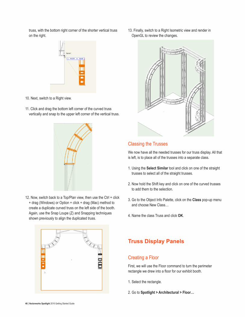
46 | Vectorworks Spotlight 2016 Getting Started Guide
truss, with the bottom right corner of the shorter vertical truss on the right.
10. Next, switch to a Right view.
11. Click and drag the bottom left corner of the curved truss vertically and snap to the upper left corner of the vertical truss.
12. Now, switch back to a Top/Plan view, then use the Ctrl + click + drag (Windows) or Option + click + drag (Mac) method to create a duplicate curved truss on the left side of the booth. Again, use the Snap Loupe (Z) and Snapping techniques shown previously to align the duplicated truss.
13. Finally, switch to a Right Isometric view and render in OpenGL to review the changes.
Classing the TrussesWe now have all the needed trusses for our truss display. All that is left, is to place all of the trusses into a separate class.
1. Using the Select Similar tool and click on one of the straight trusses to select all of the straight trusses.
2. Now hold the Shift key and click on one of the curved trusses to add them to the selection.
3. Go to the Object Info Palette, click on the Class pop-up menu and choose New Class…
4. Name the class Truss and click OK.
Truss Display Panels
Creating a FloorFirst, we will use the Floor command to turn the perimeter rectangle we drew into a floor for our exhibit booth.
1. Select the rectangle.
2. Go to Spotlight > Architectural > Floor…
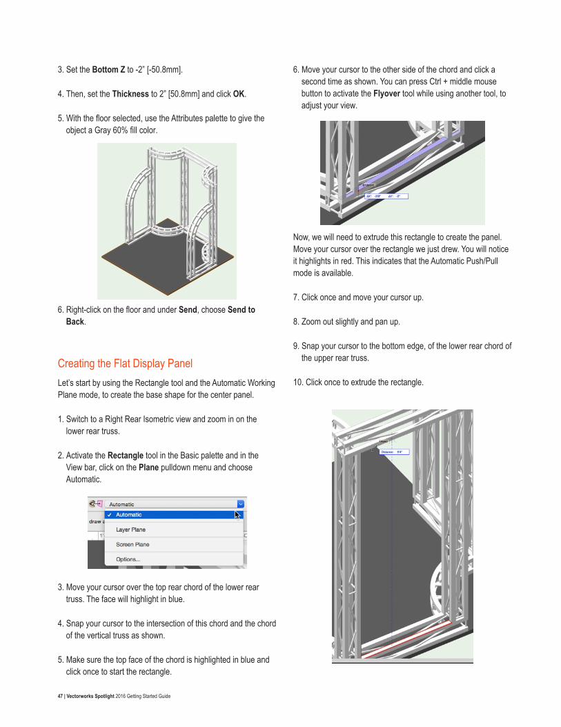
47 | Vectorworks Spotlight 2016 Getting Started Guide
3. Set the Bottom Z to -2” [-50.8mm].
4. Then, set the Thickness to 2” [50.8mm] and click OK.
5. With the floor selected, use the Attributes palette to give the object a Gray 60% fill color.
6. Right-click on the floor and under Send, choose Send to Back.
Creating the Flat Display PanelLet’s start by using the Rectangle tool and the Automatic Working Plane mode, to create the base shape for the center panel.
1. Switch to a Right Rear Isometric view and zoom in on the lower rear truss.
2. Activate the Rectangle tool in the Basic palette and in the View bar, click on the Plane pulldown menu and choose Automatic.
3. Move your cursor over the top rear chord of the lower rear truss. The face will highlight in blue.
4. Snap your cursor to the intersection of this chord and the chord of the vertical truss as shown.
5. Make sure the top face of the chord is highlighted in blue and click once to start the rectangle.
6. Move your cursor to the other side of the chord and click a second time as shown. You can press Ctrl + middle mouse button to activate the Flyover tool while using another tool, to adjust your view.
Now, we will need to extrude this rectangle to create the panel. Move your cursor over the rectangle we just drew. You will notice it highlights in red. This indicates that the Automatic Push/Pull mode is available.
7. Click once and move your cursor up.
8. Zoom out slightly and pan up.
9. Snap your cursor to the bottom edge, of the lower rear chord of the upper rear truss.
10. Click once to extrude the rectangle.
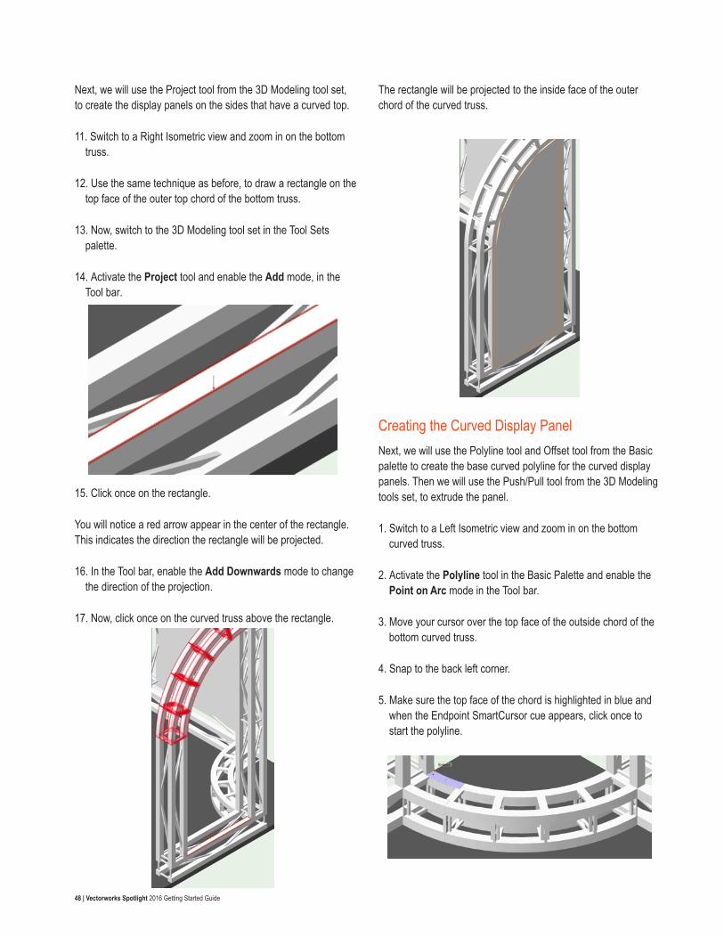
48 | Vectorworks Spotlight 2016 Getting Started Guide
Next, we will use the Project tool from the 3D Modeling tool set, to create the display panels on the sides that have a curved top.
11. Switch to a Right Isometric view and zoom in on the bottom truss.
12. Use the same technique as before, to draw a rectangle on the top face of the outer top chord of the bottom truss.
13. Now, switch to the 3D Modeling tool set in the Tool Sets palette.
14. Activate the Project tool and enable the Add mode, in the Tool bar.
15. Click once on the rectangle.
You will notice a red arrow appear in the center of the rectangle. This indicates the direction the rectangle will be projected.
16. In the Tool bar, enable the Add Downwards mode to change the direction of the projection.
17. Now, click once on the curved truss above the rectangle.
The rectangle will be projected to the inside face of the outer chord of the curved truss.
Creating the Curved Display PanelNext, we will use the Polyline tool and Offset tool from the Basic palette to create the base curved polyline for the curved display panels. Then we will use the Push/Pull tool from the 3D Modeling tools set, to extrude the panel.
1. Switch to a Left Isometric view and zoom in on the bottom curved truss.
2. Activate the Polyline tool in the Basic Palette and enable the Point on Arc mode in the Tool bar.
3. Move your cursor over the top face of the outside chord of the bottom curved truss.
4. Snap to the back left corner.
5. Make sure the top face of the chord is highlighted in blue and when the Endpoint SmartCursor cue appears, click once to start the polyline.
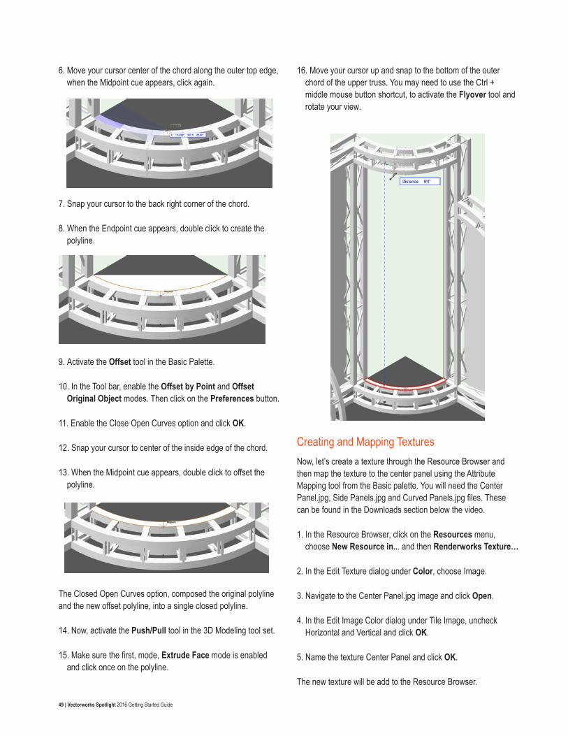
49 | Vectorworks Spotlight 2016 Getting Started Guide
6. Move your cursor center of the chord along the outer top edge, when the Midpoint cue appears, click again.
7. Snap your cursor to the back right corner of the chord.
8. When the Endpoint cue appears, double click to create the polyline.
9. Activate the Offset tool in the Basic Palette.
10. In the Tool bar, enable the Offset by Point and Offset Original Object modes. Then click on the Preferences button.
11. Enable the Close Open Curves option and click OK.
12. Snap your cursor to center of the inside edge of the chord.
13. When the Midpoint cue appears, double click to offset the polyline.
The Closed Open Curves option, composed the original polyline and the new offset polyline, into a single closed polyline.
14. Now, activate the Push/Pull tool in the 3D Modeling tool set.
15. Make sure the first, mode, Extrude Face mode is enabled and click once on the polyline.
16. Move your cursor up and snap to the bottom of the outer chord of the upper truss. You may need to use the Ctrl + middle mouse button shortcut, to activate the Flyover tool and rotate your view.
Creating and Mapping TexturesNow, let’s create a texture through the Resource Browser and then map the texture to the center panel using the Attribute Mapping tool from the Basic palette. You will need the Center Panel.jpg, Side Panels.jpg and Curved Panels.jpg files. These can be found in the Downloads section below the video.
1. In the Resource Browser, click on the Resources menu, choose New Resource in... and then Renderworks Texture…
2. In the Edit Texture dialog under Color, choose Image.
3. Navigate to the Center Panel.jpg image and click Open.
4. In the Edit Image Color dialog under Tile Image, uncheck Horizontal and Vertical and click OK.
5. Name the texture Center Panel and click OK.
The new texture will be add to the Resource Browser.
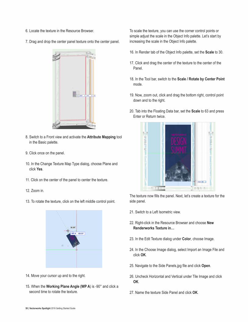
50 | Vectorworks Spotlight 2016 Getting Started Guide
6. Locate the texture in the Resource Browser.
7. Drag and drop the center panel texture onto the center panel.
8. Switch to a Front view and activate the Attribute Mapping tool in the Basic palette.
9. Click once on the panel.
10. In the Change Texture Map Type dialog, choose Plane and click Yes.
11. Click on the center of the panel to center the texture.
12. Zoom in.
13. To rotate the texture, click on the left middle control point.
14. Move your cursor up and to the right.
15. When the Working Plane Angle (WP A) is -90° and click a second time to rotate the texture.
To scale the texture, you can use the corner control points or simple adjust the scale in the Object Info palette. Let’s start by increasing the scale in the Object Info palette.
16. In Render tab of the Object Info palette, set the Scale to 30.
17. Click and drag the center of the texture to the center of the Panel.
18. In the Tool bar, switch to the Scale / Rotate by Center Point mode.
19. Now, zoom out, click and drag the bottom right, control point down and to the right.
20. Tab into the Floating Data bar, set the Scale to 63 and press Enter or Return twice.
The texture now fills the panel. Next, let’s create a texture for the side panel.
21. Switch to a Left Isometric view.
22. Right-click in the Resource Browser and choose New Renderworks Texture in…
23. In the Edit Texture dialog under Color, choose Image.
24. In the Choose Image dialog, select Import an Image File and click OK.
25. Navigate to the Side Panels.jpg file and click Open.
26. Uncheck Horizontal and Vertical under Tile Image and click OK.
27. Name the texture Side Panel and click OK.
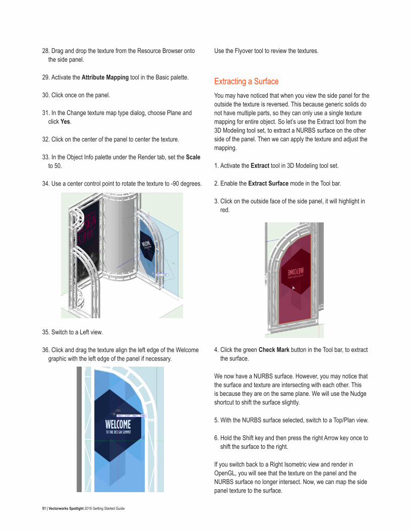
51 | Vectorworks Spotlight 2016 Getting Started Guide
28. Drag and drop the texture from the Resource Browser onto the side panel.
29. Activate the Attribute Mapping tool in the Basic palette.
30. Click once on the panel.
31. In the Change texture map type dialog, choose Plane and click Yes.
32. Click on the center of the panel to center the texture.
33. In the Object Info palette under the Render tab, set the Scale to 50.
34. Use a center control point to rotate the texture to -90 degrees.
35. Switch to a Left view.
36. Click and drag the texture align the left edge of the Welcome graphic with the left edge of the panel if necessary.
Use the Flyover tool to review the textures.
Extracting a SurfaceYou may have noticed that when you view the side panel for the outside the texture is reversed. This because generic solids do not have multiple parts, so they can only use a single texture mapping for entire object. So let’s use the Extract tool from the 3D Modeling tool set, to extract a NURBS surface on the other side of the panel. Then we can apply the texture and adjust the mapping.
1. Activate the Extract tool in 3D Modeling tool set.
2. Enable the Extract Surface mode in the Tool bar.
3. Click on the outside face of the side panel, it will highlight in red.
4. Click the green Check Mark button in the Tool bar, to extract the surface.
We now have a NURBS surface. However, you may notice that the surface and texture are intersecting with each other. This is because they are on the same plane. We will use the Nudge shortcut to shift the surface slightly.
5. With the NURBS surface selected, switch to a Top/Plan view.
6. Hold the Shift key and then press the right Arrow key once to shift the surface to the right.
If you switch back to a Right Isometric view and render in OpenGL, you will see that the texture on the panel and the NURBS surface no longer intersect. Now, we can map the side panel texture to the surface.
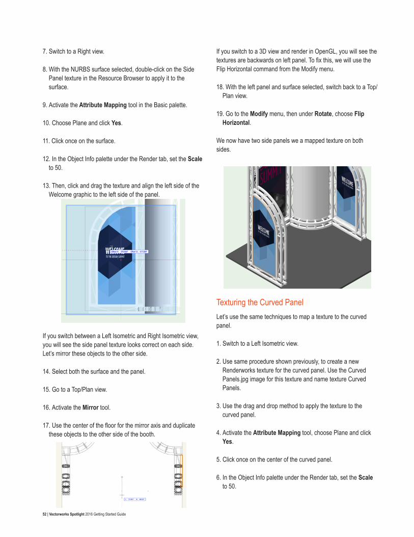
52 | Vectorworks Spotlight 2016 Getting Started Guide
7. Switch to a Right view.
8. With the NURBS surface selected, double-click on the Side Panel texture in the Resource Browser to apply it to the surface.
9. Activate the Attribute Mapping tool in the Basic palette.
10. Choose Plane and click Yes.
11. Click once on the surface.
12. In the Object Info palette under the Render tab, set the Scale to 50.
13. Then, click and drag the texture and align the left side of the Welcome graphic to the left side of the panel.
If you switch between a Left Isometric and Right Isometric view, you will see the side panel texture looks correct on each side. Let’s mirror these objects to the other side.
14. Select both the surface and the panel.
15. Go to a Top/Plan view.
16. Activate the Mirror tool.
17. Use the center of the floor for the mirror axis and duplicate these objects to the other side of the booth.
If you switch to a 3D view and render in OpenGL, you will see the textures are backwards on left panel. To fix this, we will use the Flip Horizontal command from the Modify menu.
18. With the left panel and surface selected, switch back to a Top/Plan view.
19. Go to the Modify menu, then under Rotate, choose Flip Horizontal.
We now have two side panels we a mapped texture on both sides.
Texturing the Curved PanelLet’s use the same techniques to map a texture to the curved panel.
1. Switch to a Left Isometric view.
2. Use same procedure shown previously, to create a new Renderworks texture for the curved panel. Use the Curved Panels.jpg image for this texture and name texture Curved Panels.
3. Use the drag and drop method to apply the texture to the curved panel.
4. Activate the Attribute Mapping tool, choose Plane and click Yes.
5. Click once on the center of the curved panel.
6. In the Object Info palette under the Render tab, set the Scale to 50.
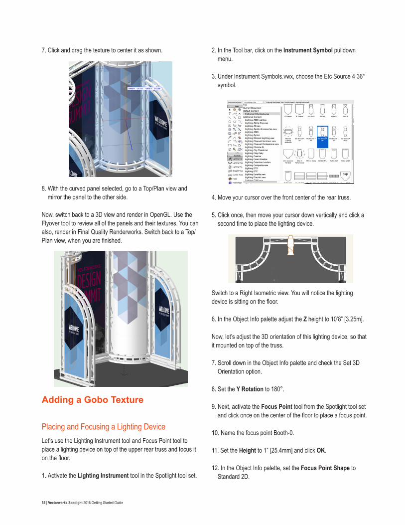
53 | Vectorworks Spotlight 2016 Getting Started Guide
7. Click and drag the texture to center it as shown.
8. With the curved panel selected, go to a Top/Plan view and mirror the panel to the other side.
Now, switch back to a 3D view and render in OpenGL. Use the Flyover tool to review all of the panels and their textures. You can also, render in Final Quality Renderworks. Switch back to a Top/Plan view, when you are finished.
Adding a Gobo Texture
Placing and Focusing a Lighting DeviceLet’s use the Lighting Instrument tool and Focus Point tool to place a lighting device on top of the upper rear truss and focus it on the floor.
1. Activate the Lighting Instrument tool in the Spotlight tool set.
2. In the Tool bar, click on the Instrument Symbol pulldown menu.
3. Under Instrument Symbols.vwx, choose the Etc Source 4 36° symbol.
4. Move your cursor over the front center of the rear truss.
5. Click once, then move your cursor down vertically and click a second time to place the lighting device.
Switch to a Right Isometric view. You will notice the lighting device is sitting on the floor.
6. In the Object Info palette adjust the Z height to 10’8” [3.25m].
Now, let’s adjust the 3D orientation of this lighting device, so that it mounted on top of the truss.
7. Scroll down in the Object Info palette and check the Set 3D Orientation option.
8. Set the Y Rotation to 180°.
9. Next, activate the Focus Point tool from the Spotlight tool set and click once on the center of the floor to place a focus point.
10. Name the focus point Booth-0.
11. Set the Height to 1” [25.4mm] and click OK.
12. In the Object Info palette, set the Focus Point Shape to Standard 2D.
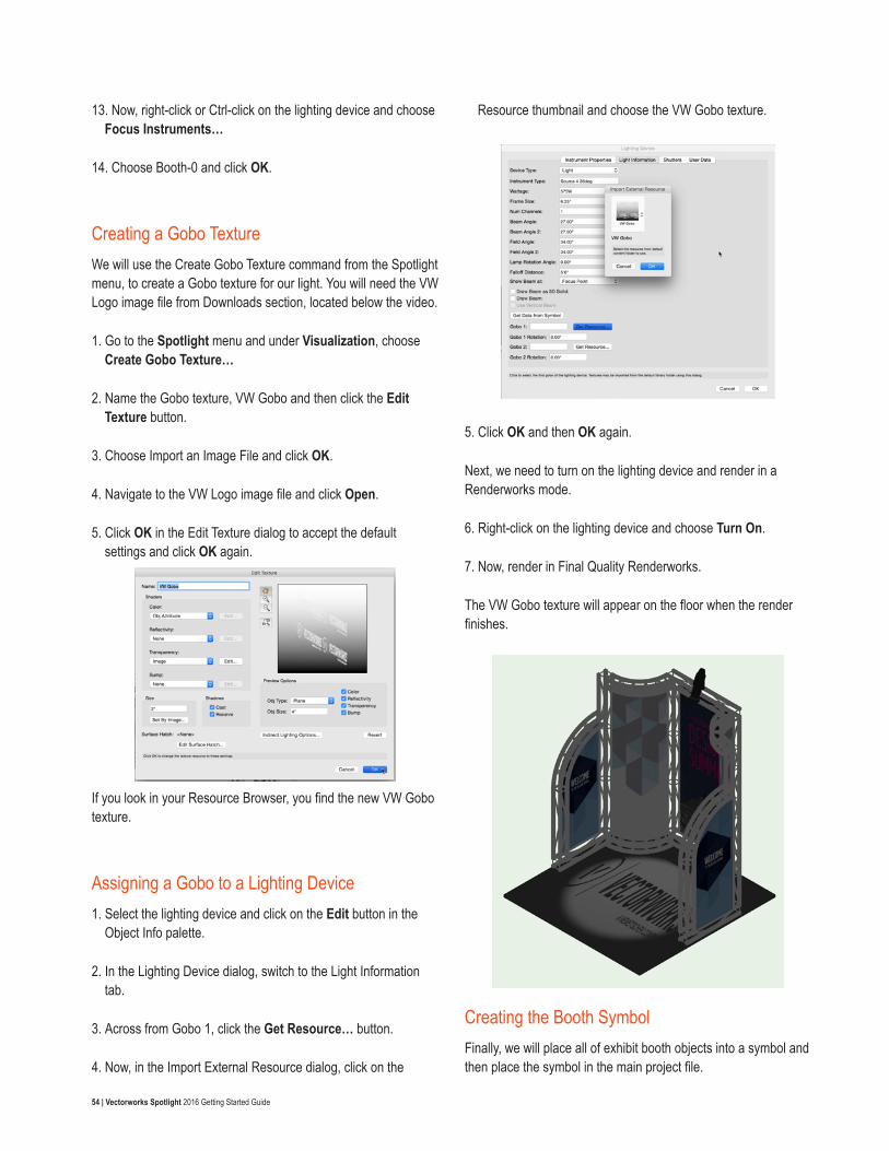
54 | Vectorworks Spotlight 2016 Getting Started Guide
13. Now, right-click or Ctrl-click on the lighting device and choose Focus Instruments…
14. Choose Booth-0 and click OK.
Creating a Gobo TextureWe will use the Create Gobo Texture command from the Spotlight menu, to create a Gobo texture for our light. You will need the VW Logo image file from Downloads section, located below the video.
1. Go to the Spotlight menu and under Visualization, choose Create Gobo Texture…
2. Name the Gobo texture, VW Gobo and then click the Edit Texture button.
3. Choose Import an Image File and click OK.
4. Navigate to the VW Logo image file and click Open.
5. Click OK in the Edit Texture dialog to accept the default settings and click OK again.
If you look in your Resource Browser, you find the new VW Gobo texture.
Assigning a Gobo to a Lighting Device1. Select the lighting device and click on the Edit button in the
Object Info palette.
2. In the Lighting Device dialog, switch to the Light Information tab.
3. Across from Gobo 1, click the Get Resource… button.
4. Now, in the Import External Resource dialog, click on the
Resource thumbnail and choose the VW Gobo texture.
5. Click OK and then OK again.
Next, we need to turn on the lighting device and render in a Renderworks mode.
6. Right-click on the lighting device and choose Turn On.
7. Now, render in Final Quality Renderworks.
The VW Gobo texture will appear on the floor when the render finishes.
Creating the Booth SymbolFinally, we will place all of exhibit booth objects into a symbol and then place the symbol in the main project file.
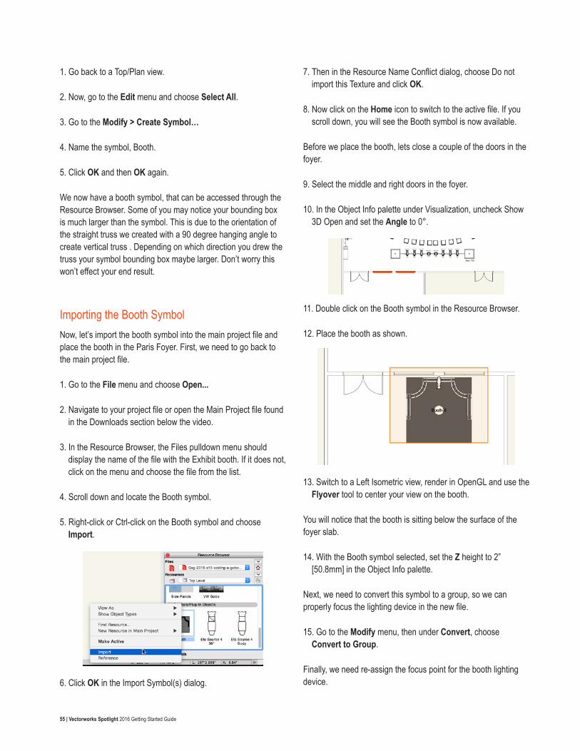
55 | Vectorworks Spotlight 2016 Getting Started Guide
1. Go back to a Top/Plan view.
2. Now, go to the Edit menu and choose Select All.
3. Go to the Modify > Create Symbol…
4. Name the symbol, Booth.
5. Click OK and then OK again.
We now have a booth symbol, that can be accessed through the Resource Browser. Some of you may notice your bounding box is much larger than the symbol. This is due to the orientation of the straight truss we created with a 90 degree hanging angle to create vertical truss . Depending on which direction you drew the truss your symbol bounding box maybe larger. Don’t worry this won’t effect your end result.
Importing the Booth Symbol Now, let’s import the booth symbol into the main project file and place the booth in the Paris Foyer. First, we need to go back to the main project file.
1. Go to the File menu and choose Open...
2. Navigate to your project file or open the Main Project file found in the Downloads section below the video.
3. In the Resource Browser, the Files pulldown menu should display the name of the file with the Exhibit booth. If it does not, click on the menu and choose the file from the list.
4. Scroll down and locate the Booth symbol.
5. Right-click or Ctrl-click on the Booth symbol and choose Import.
6. Click OK in the Import Symbol(s) dialog.
7. Then in the Resource Name Conflict dialog, choose Do not import this Texture and click OK.
8. Now click on the Home icon to switch to the active file. If you scroll down, you will see the Booth symbol is now available.
Before we place the booth, lets close a couple of the doors in the foyer.
9. Select the middle and right doors in the foyer.
10. In the Object Info palette under Visualization, uncheck Show 3D Open and set the Angle to 0°.
11. Double click on the Booth symbol in the Resource Browser.
12. Place the booth as shown.
13. Switch to a Left Isometric view, render in OpenGL and use the Flyover tool to center your view on the booth.
You will notice that the booth is sitting below the surface of the foyer slab.
14. With the Booth symbol selected, set the Z height to 2” [50.8mm] in the Object Info palette.
Next, we need to convert this symbol to a group, so we can properly focus the lighting device in the new file.
15. Go to the Modify menu, then under Convert, choose Convert to Group.
Finally, we need re-assign the focus point for the booth lighting device.
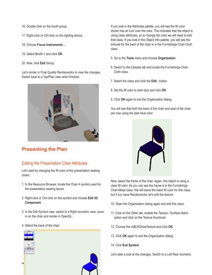
56 | Vectorworks Spotlight 2016 Getting Started Guide
16. Double click on the booth group.
17. Right-click or Ctrl-click on the lighting device.
18. Choose Focus Instruments…
19. Select Booth-1 and click OK.
20. Now, click Exit Group.
Let’s render in Final Quality Renderworks to view the changes. Switch back to a Top/Plan view when finished.
Presenting the Plan
Editing the Presentation Chair AttributesLet’s start by changing the fill color of the presentation seating chairs.
1. In the Resource Browser, locate the Chair 4 symbol used for the presentation seating layout.
2. Right-click or Ctrl-click on the symbol and choose Edit 3D Component.
3. In the Edit Symbol view, switch to a Right Isometric view, zoom in on the chair and render in OpenGL.
4. Select the back of the chair.
If you look in the Attributes palette, you will see the fill color shown has an icon over the color. This indicates that the object is using class attributes, so to change the color we will need to edit that class. If you look in the Object Info palette, you will see the extrude for the back of the chair is in the Furnishings-Chair-Cloth class.
5. Go to the Tools menu and choose Organization.
6. Switch to the Classes tab and locate the Furnishings-Chair-Cloth class.
7. Select the class and click the Edit.. button.
8. Set the fill color to dark blue and click OK.
9. Click OK again to exit the Organization dialog.
You will see that both the back of the chair and seat of the chair, are now using the dark blue color.
Now, select the frame of the chair. Again, this object is using a class fill color. As you can see the frame is in the Furnishings-Chair-Metal class. We will leave the black fill color for this class, but if you have Renderworks, let’s edit the texture.
10. Open the Organization dialog again and edit this class.
11. Click on the Other tab, enable the Texture / Surface Hatch option and click on the Texture thumbnail.
12. Choose the vsBLKGlossTexture and click OK.
13. Click OK again to exit the Organization dialog.
14. Click Exit Symbol.
Let’s take a look at the changes. Switch to a Left Rear Isometric
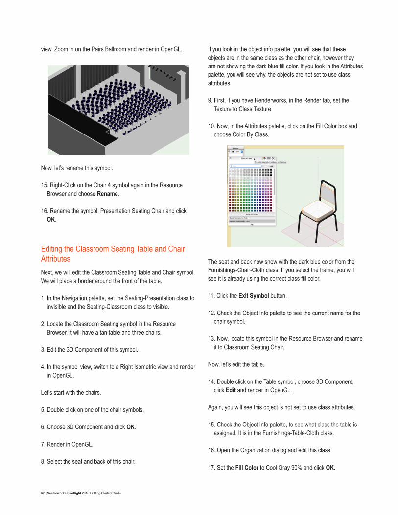
57 | Vectorworks Spotlight 2016 Getting Started Guide
view. Zoom in on the Pairs Ballroom and render in OpenGL.
Now, let’s rename this symbol.
15. Right-Click on the Chair 4 symbol again in the Resource Browser and choose Rename.
16. Rename the symbol, Presentation Seating Chair and click OK.
Editing the Classroom Seating Table and Chair AttributesNext, we will edit the Classroom Seating Table and Chair symbol. We will place a border around the front of the table.
1. In the Navigation palette, set the Seating-Presentation class to invisible and the Seating-Classroom class to visible.
2. Locate the Classroom Seating symbol in the Resource Browser, it will have a tan table and three chairs.
3. Edit the 3D Component of this symbol.
4. In the symbol view, switch to a Right Isometric view and render in OpenGL.
Let’s start with the chairs.
5. Double click on one of the chair symbols.
6. Choose 3D Component and click OK.
7. Render in OpenGL.
8. Select the seat and back of this chair.
If you look in the object info palette, you will see that these objects are in the same class as the other chair, however they are not showing the dark blue fill color. If you look in the Attributes palette, you will see why, the objects are not set to use class attributes.
9. First, if you have Renderworks, in the Render tab, set the Texture to Class Texture.
10. Now, in the Attributes palette, click on the Fill Color box and choose Color By Class.
The seat and back now show with the dark blue color from the Furnishings-Chair-Cloth class. If you select the frame, you will see it is already using the correct class fill color.
11. Click the Exit Symbol button.
12. Check the Object Info palette to see the current name for the chair symbol.
13. Now, locate this symbol in the Resource Browser and rename it to Classroom Seating Chair.
Now, let’s edit the table.
14. Double click on the Table symbol, choose 3D Component, click Edit and render in OpenGL.
Again, you will see this object is not set to use class attributes.
15. Check the Object Info palette, to see what class the table is assigned. It is in the Furnishings-Table-Cloth class.
16. Open the Organization dialog and edit this class.
17. Set the Fill Color to Cool Gray 90% and click OK.
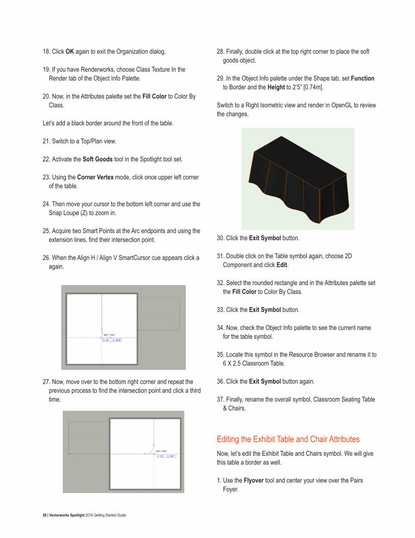
58 | Vectorworks Spotlight 2016 Getting Started Guide
18. Click OK again to exit the Organization dialog.
19. If you have Renderworks, choose Class Texture In the Render tab of the Object Info Palette.
20. Now, in the Attributes palette set the Fill Color to Color By Class.
Let’s add a black border around the front of the table.
21. Switch to a Top/Plan view.
22. Activate the Soft Goods tool in the Spotlight tool set.
23. Using the Corner Vertex mode, click once upper left corner of the table.
24. Then move your cursor to the bottom left corner and use the Snap Loupe (Z) to zoom in.
25. Acquire two Smart Points at the Arc endpoints and using the extension lines, find their intersection point.
26. When the Align H / Align V SmartCursor cue appears click a again.
27. Now, move over to the bottom right corner and repeat the previous process to find the intersection point and click a third time.
28. Finally, double click at the top right corner to place the soft goods object.
29. In the Object Info palette under the Shape tab, set Function to Border and the Height to 2’5” [0.74m].
Switch to a Right Isometric view and render in OpenGL to review the changes.
30. Click the Exit Symbol button.
31. Double click on the Table symbol again, choose 2D Component and click Edit.
32. Select the rounded rectangle and in the Attributes palette set the Fill Color to Color By Class.
33. Click the Exit Symbol button.
34. Now, check the Object Info palette to see the current name for the table symbol.
35. Locate this symbol in the Resource Browser and rename it to 6 X 2.5 Classroom Table.
36. Click the Exit Symbol button again.
37. Finally, rename the overall symbol, Classroom Seating Table & Chairs.
Editing the Exhibit Table and Chair AttributesNow, let’s edit the Exhibit Table and Chairs symbol. We will give this table a border as well.
1. Use the Flyover tool and center your view over the Pairs Foyer.
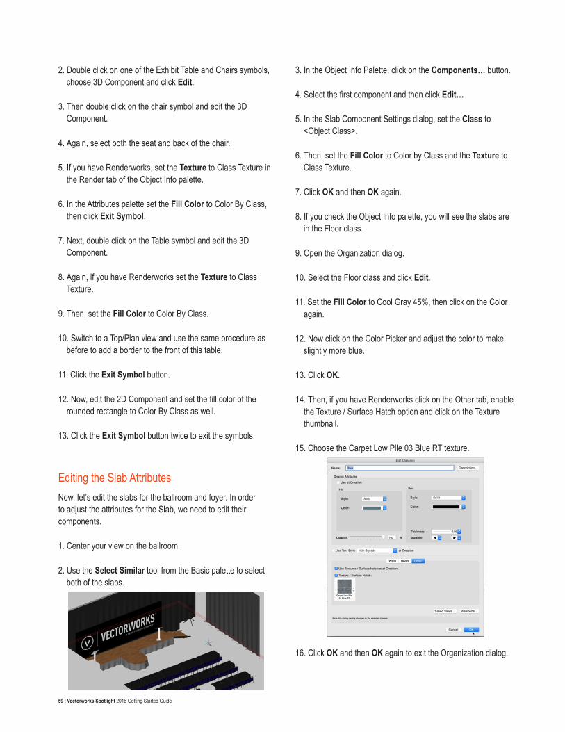
59 | Vectorworks Spotlight 2016 Getting Started Guide
2. Double click on one of the Exhibit Table and Chairs symbols, choose 3D Component and click Edit.
3. Then double click on the chair symbol and edit the 3D Component.
4. Again, select both the seat and back of the chair.
5. If you have Renderworks, set the Texture to Class Texture in the Render tab of the Object Info palette.
6. In the Attributes palette set the Fill Color to Color By Class, then click Exit Symbol.
7. Next, double click on the Table symbol and edit the 3D Component.
8. Again, if you have Renderworks set the Texture to Class Texture.
9. Then, set the Fill Color to Color By Class.
10. Switch to a Top/Plan view and use the same procedure as before to add a border to the front of this table.
11. Click the Exit Symbol button.
12. Now, edit the 2D Component and set the fill color of the rounded rectangle to Color By Class as well.
13. Click the Exit Symbol button twice to exit the symbols.
Editing the Slab AttributesNow, let’s edit the slabs for the ballroom and foyer. In order to adjust the attributes for the Slab, we need to edit their components.
1. Center your view on the ballroom.
2. Use the Select Similar tool from the Basic palette to select both of the slabs.
3. In the Object Info Palette, click on the Components… button.
4. Select the first component and then click Edit…
5. In the Slab Component Settings dialog, set the Class to <Object Class>.
6. Then, set the Fill Color to Color by Class and the Texture to Class Texture.
7. Click OK and then OK again.
8. If you check the Object Info palette, you will see the slabs are in the Floor class.
9. Open the Organization dialog.
10. Select the Floor class and click Edit.
11. Set the Fill Color to Cool Gray 45%, then click on the Color again.
12. Now click on the Color Picker and adjust the color to make slightly more blue.
13. Click OK.
14. Then, if you have Renderworks click on the Other tab, enable the Texture / Surface Hatch option and click on the Texture thumbnail.
15. Choose the Carpet Low Pile 03 Blue RT texture.
16. Click OK and then OK again to exit the Organization dialog.
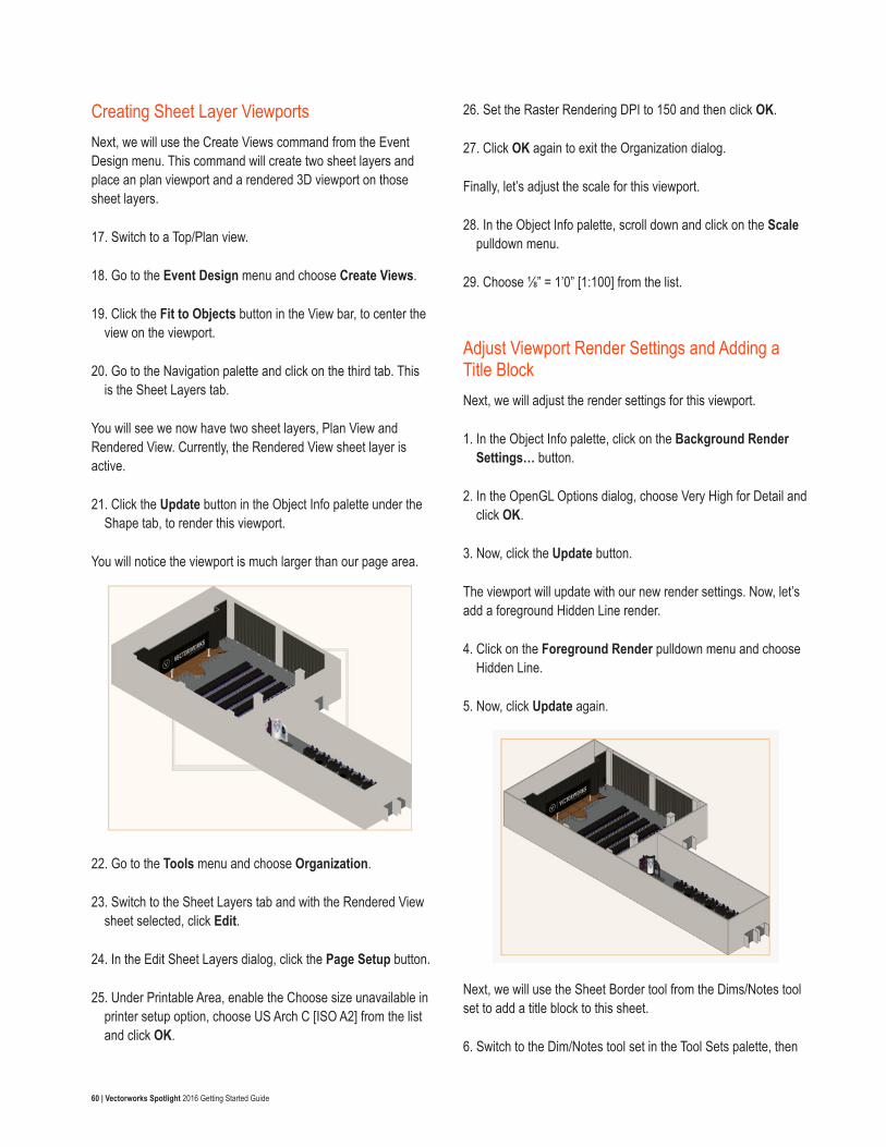
60 | Vectorworks Spotlight 2016 Getting Started Guide
Creating Sheet Layer ViewportsNext, we will use the Create Views command from the Event Design menu. This command will create two sheet layers and place an plan viewport and a rendered 3D viewport on those sheet layers.
17. Switch to a Top/Plan view.
18. Go to the Event Design menu and choose Create Views.
19. Click the Fit to Objects button in the View bar, to center the view on the viewport.
20. Go to the Navigation palette and click on the third tab. This is the Sheet Layers tab.
You will see we now have two sheet layers, Plan View and Rendered View. Currently, the Rendered View sheet layer is active.
21. Click the Update button in the Object Info palette under the Shape tab, to render this viewport.
You will notice the viewport is much larger than our page area.
22. Go to the Tools menu and choose Organization.
23. Switch to the Sheet Layers tab and with the Rendered View sheet selected, click Edit.
24. In the Edit Sheet Layers dialog, click the Page Setup button.
25. Under Printable Area, enable the Choose size unavailable in printer setup option, choose US Arch C [ISO A2] from the list and click OK.
26. Set the Raster Rendering DPI to 150 and then click OK.
27. Click OK again to exit the Organization dialog.
Finally, let’s adjust the scale for this viewport.
28. In the Object Info palette, scroll down and click on the Scale pulldown menu.
29. Choose ⅛” = 1’0” [1:100] from the list.
Adjust Viewport Render Settings and Adding a Title BlockNext, we will adjust the render settings for this viewport.
1. In the Object Info palette, click on the Background Render Settings… button.
2. In the OpenGL Options dialog, choose Very High for Detail and click OK.
3. Now, click the Update button.
The viewport will update with our new render settings. Now, let’s add a foreground Hidden Line render.
4. Click on the Foreground Render pulldown menu and choose Hidden Line.
5. Now, click Update again.
Next, we will use the Sheet Border tool from the Dims/Notes tool set to add a title block to this sheet.
6. Switch to the Dim/Notes tool set in the Tool Sets palette, then
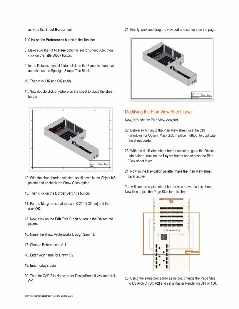
61 | Vectorworks Spotlight 2016 Getting Started Guide
activate the Sheet Border tool.
7. Click on the Preferences button in the Tool bar.
8. Make sure the Fit to Page option is set for Sheet Size, then click on the Title Block button.
9. In the Defaults symbol folder, click on the Symbols thumbnail and choose the Spotlight Simple Title Block.
10. Then click OK and OK again.
11. Now double click anywhere on the sheet to place the sheet border.
12. With the sheet border selected, scroll down in the Object Info palette and uncheck the Show Grids option.
13. Then click on the Border Settings button.
14. For the Margins, set all sides to 0.25” [6.35mm] and then click OK.
15. Now, click on the Edit Title Block button in the Object Info palette.
16. Name the show, Vectorworks Design Summit.
17. Change Reference to A-1
18. Enter your name for Drawn By.
19. Enter today’s date
20. Then for CAD File Name, enter DesignSummit.vwx and click OK.
21. Finally, click and drag the viewport and center it on the page.
Modifying the Plan View Sheet LayerNow, let’s edit the Plan View viewport.
22. Before switching to the Plan View sheet, use the Ctrl (Windows) or Option (Mac) click in place method, to duplicate the sheet border.
23. With the duplicated sheet border selected, go to the Object Info palette, click on the Layers button and choose the Plan View sheet layer.
24. Now, in the Navigation palette, make the Plan View sheet layer active.
You will see the copied sheet border was moved to this sheet. Now let’s adjust the Page Size for this sheet.
25. Using the same procedure as before, change the Page Size to US Arch C [ISO A2] and set a Raster Rendering DPI of 150.
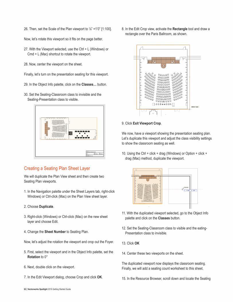
62 | Vectorworks Spotlight 2016 Getting Started Guide
26. Then, set the Scale of the Plan viewport to ⅛” =1’0” [1:100].
Now, let’s rotate this viewport so it fits on the page better.
27. With the Viewport selected, use the Ctrl + L (Windows) or Cmd + L (Mac) shortcut to rotate the viewport.
28. Now, center the viewport on the sheet.
Finally, let’s turn on the presentation seating for this viewport.
29. In the Object Info palette, click on the Classes… button.
30. Set the Seating-Classroom class to invisible and the Seating-Presentation class to visible.
Creating a Seating Plan Sheet LayerWe will duplicate the Plan View sheet and then create two Seating Plan viewports.
1. In the Navigation palette under the Sheet Layers tab, right-click Windows) or Ctrl-click (Mac) on the Plan View sheet layer.
2. Choose Duplicate.
3. Right-click (Windows) or Ctrl-click (Mac) on the new sheet layer and choose Edit.
4. Change the Sheet Number to Seating Plan.
Now, let’s adjust the rotation the viewport and crop out the Foyer.
5. First, select the viewport and in the Object Info palette, set the Rotation to 0°
6. Next, double click on the viewport.
7. In the Edit Viewport dialog, choose Crop and click OK.
8. In the Edit Crop view, activate the Rectangle tool and draw a rectangle over the Paris Ballroom, as shown.
9. Click Exit Viewport Crop.
We now, have a viewport showing the presentation seating plan. Let’s duplicate this viewport and adjust the class visibility settings to show the classroom seating as well.
10. Using the Ctrl + click + drag (Windows) or Option + click + drag (Mac) method, duplicate the viewport.
11. With the duplicated viewport selected, go to the Object Info palette and click on the Classes button.
12. Set the Seating-Classroom class to visible and the eating-Presentation class to invisible.
13. Click OK
14. Center these two viewports on the sheet.
The duplicated viewport now displays the classroom seating. Finally, we will add a seating count worksheet to this sheet.
15. In the Resource Browser, scroll down and locate the Seating
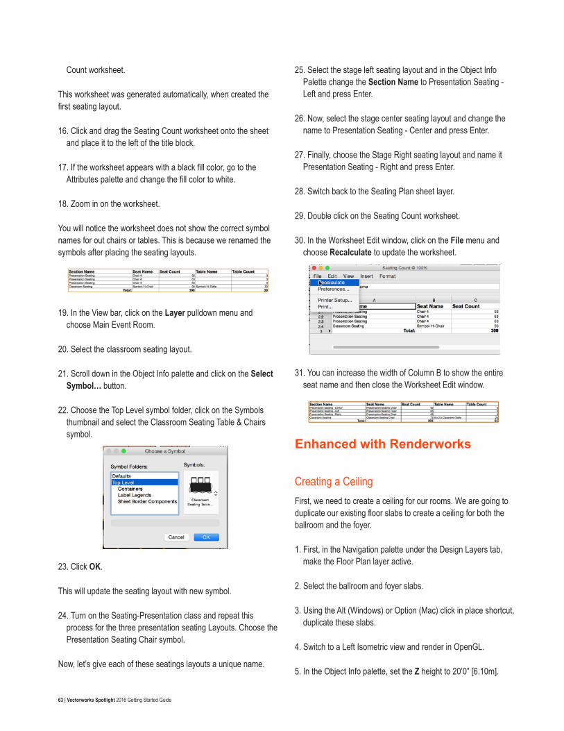
63 | Vectorworks Spotlight 2016 Getting Started Guide
Count worksheet.
This worksheet was generated automatically, when created the first seating layout.
16. Click and drag the Seating Count worksheet onto the sheet and place it to the left of the title block.
17. If the worksheet appears with a black fill color, go to the Attributes palette and change the fill color to white.
18. Zoom in on the worksheet.
You will notice the worksheet does not show the correct symbol names for out chairs or tables. This is because we renamed the symbols after placing the seating layouts.
19. In the View bar, click on the Layer pulldown menu and choose Main Event Room.
20. Select the classroom seating layout.
21. Scroll down in the Object Info palette and click on the Select Symbol… button.
22. Choose the Top Level symbol folder, click on the Symbols thumbnail and select the Classroom Seating Table & Chairs symbol.
23. Click OK.
This will update the seating layout with new symbol.
24. Turn on the Seating-Presentation class and repeat this process for the three presentation seating Layouts. Choose the Presentation Seating Chair symbol.
Now, let’s give each of these seatings layouts a unique name.
25. Select the stage left seating layout and in the Object Info Palette change the Section Name to Presentation Seating - Left and press Enter.
26. Now, select the stage center seating layout and change the name to Presentation Seating - Center and press Enter.
27. Finally, choose the Stage Right seating layout and name it Presentation Seating - Right and press Enter.
28. Switch back to the Seating Plan sheet layer.
29. Double click on the Seating Count worksheet.
30. In the Worksheet Edit window, click on the File menu and choose Recalculate to update the worksheet.
31. You can increase the width of Column B to show the entire seat name and then close the Worksheet Edit window.
Enhanced with Renderworks
Creating a CeilingFirst, we need to create a ceiling for our rooms. We are going to duplicate our existing floor slabs to create a ceiling for both the ballroom and the foyer.
1. First, in the Navigation palette under the Design Layers tab, make the Floor Plan layer active.
2. Select the ballroom and foyer slabs.
3. Using the Alt (Windows) or Option (Mac) click in place shortcut, duplicate these slabs.
4. Switch to a Left Isometric view and render in OpenGL.
5. In the Object Info palette, set the Z height to 20’0” [6.10m].
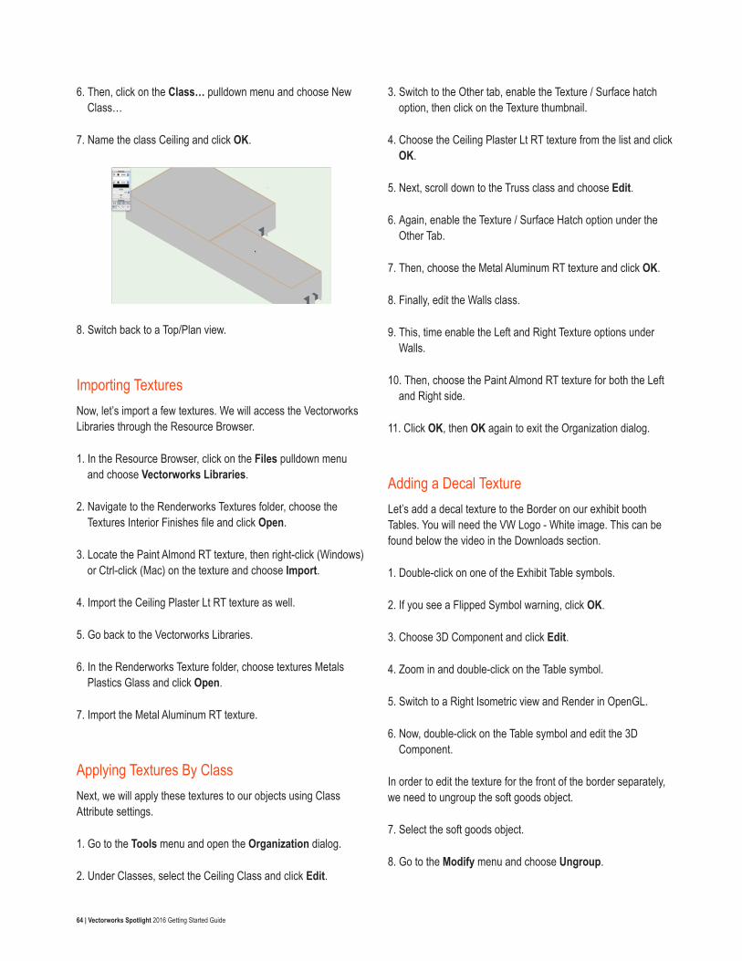
64 | Vectorworks Spotlight 2016 Getting Started Guide
6. Then, click on the Class… pulldown menu and choose New Class…
7. Name the class Ceiling and click OK.
8. Switch back to a Top/Plan view.
Importing Textures Now, let’s import a few textures. We will access the Vectorworks Libraries through the Resource Browser.
1. In the Resource Browser, click on the Files pulldown menu and choose Vectorworks Libraries.
2. Navigate to the Renderworks Textures folder, choose the Textures Interior Finishes file and click Open.
3. Locate the Paint Almond RT texture, then right-click (Windows) or Ctrl-click (Mac) on the texture and choose Import.
4. Import the Ceiling Plaster Lt RT texture as well.
5. Go back to the Vectorworks Libraries.
6. In the Renderworks Texture folder, choose textures Metals Plastics Glass and click Open.
7. Import the Metal Aluminum RT texture.
Applying Textures By ClassNext, we will apply these textures to our objects using Class Attribute settings.
1. Go to the Tools menu and open the Organization dialog.
2. Under Classes, select the Ceiling Class and click Edit.
3. Switch to the Other tab, enable the Texture / Surface hatch option, then click on the Texture thumbnail.
4. Choose the Ceiling Plaster Lt RT texture from the list and click OK.
5. Next, scroll down to the Truss class and choose Edit.
6. Again, enable the Texture / Surface Hatch option under the Other Tab.
7. Then, choose the Metal Aluminum RT texture and click OK.
8. Finally, edit the Walls class.
9. This, time enable the Left and Right Texture options under Walls.
10. Then, choose the Paint Almond RT texture for both the Left and Right side.
11. Click OK, then OK again to exit the Organization dialog.
Adding a Decal TextureLet’s add a decal texture to the Border on our exhibit booth Tables. You will need the VW Logo - White image. This can be found below the video in the Downloads section.
1. Double-click on one of the Exhibit Table symbols.
2. If you see a Flipped Symbol warning, click OK.
3. Choose 3D Component and click Edit.
4. Zoom in and double-click on the Table symbol.
5. Switch to a Right Isometric view and Render in OpenGL.
6. Now, double-click on the Table symbol and edit the 3D Component.
In order to edit the texture for the front of the border separately, we need to ungroup the soft goods object.
7. Select the soft goods object.
8. Go to the Modify menu and choose Ungroup.
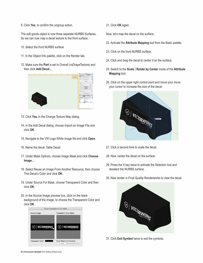
65 | Vectorworks Spotlight 2016 Getting Started Guide
9. Click Yes, to confirm the ungroup action.
The soft goods object is now three separate NURBS Surfaces. So we can now map a decal texture to the front surface.
10. Select the front NURBS surface.
11. In the Object Info palette, click on the Render tab.
12. Make sure the Part is set to Overall (vsDrapeTexture) and then click Add Decal…
13. Click Yes, in the Change Texture Map dialog.
14. In the Add Decal dialog, choose Import an Image File and click OK.
15. Navigate to the VW Logo-White image file and click Open.
16. Name the decal, Table Decal.
17. Under Mask Options, choose Image Mask and click Choose Image…
18. Select Reuse an Image From Another Resource, then choose This Decal’s Color and click OK.
19. Under Source For Mask, choose Transparent Color and then click OK.
20. In the Source Image preview box, click on the black background of the image, to choose the Transparent Color and click OK.
21. Click OK again.
Now, let’s map the decal on the surface.
22. Activate the Attribute Mapping tool from the Basic palette.
23. Click on the front NURBS surface.
24. Click and drag the decal to center it on the surface.
25. Switch to the Scale / Rotate by Center mode of the Attribute Mapping tool.
26. Click on the upper right control point and move your move your cursor to increase the size of the decal.
27. Click a second time to scale the decal.
28. Now, center the decal on the surface.
29. Press the X key twice to activate the Selection tool and deselect the NURBS surface.
30. Now render in Final Quality Renderworks to view the decal.
31. Click Exit Symbol twice to exit the symbols.
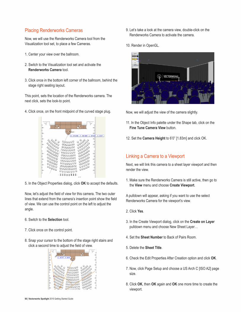
66 | Vectorworks Spotlight 2016 Getting Started Guide
Placing Renderworks CamerasNow, we will use the Renderworks Camera tool from the Visualization tool set, to place a few Cameras.
1. Center your view over the ballroom.
2. Switch to the Visualization tool set and activate the Renderworks Camera tool.
3. Click once in the bottom left corner of the ballroom, behind the stage right seating layout.
This point, sets the location of the Renderworks camera. The next click, sets the look-to point.
4. Click once, on the front midpoint of the curved stage plug.
5. In the Object Properties dialog, click OK to accept the defaults.
Now, let’s adjust the field of view for this camera. The two outer lines that extend from the camera’s insertion point show the field of view. We can use the control point on the left to adjust the angle.
6. Switch to the Selection tool.
7. Click once on the control point.
8. Snap your cursor to the bottom of the stage right stairs and click a second time to adjust the field of view.
9. Let’s take a look at the camera view, double-click on the Renderworks Camera to activate the camera.
10. Render in OpenGL.
Now, we will adjust the view of the camera slightly.
11. In the Object Info palette under the Shape tab, click on the Fine Tune Camera View button.
12. Set the Camera Height to 6’0” [1.83m] and click OK.
Linking a Camera to a ViewportNext, we will link this camera to a sheet layer viewport and then render the view.
1. Make sure the Renderworks Camera is still active, then go to the View menu and choose Create Viewport.
A pulldown will appear, asking if you want to use the select Renderworks Camera for the viewport’s view.
2. Click Yes.
3. In the Create Viewport dialog, click on the Create on Layer pulldown menu and choose New Sheet Layer…
4. Set the Sheet Number to Back of Pairs Room.
5. Delete the Sheet Title.
6. Check the Edit Properties After Creation option and click OK.
7. Now, click Page Setup and choose a US Arch C [ISO A2] page size.
8. Click OK, then OK again and OK one more time to create the viewport.
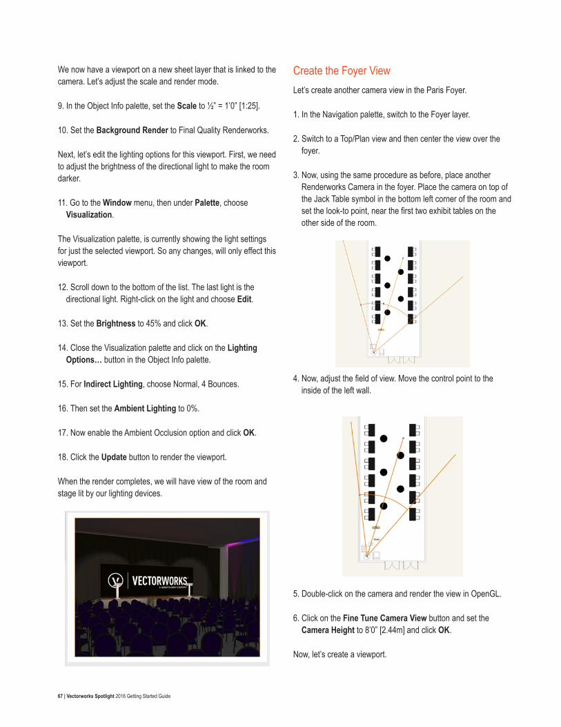
67 | Vectorworks Spotlight 2016 Getting Started Guide
We now have a viewport on a new sheet layer that is linked to the camera. Let’s adjust the scale and render mode.
9. In the Object Info palette, set the Scale to ½” = 1’0” [1:25].
10. Set the Background Render to Final Quality Renderworks.
Next, let’s edit the lighting options for this viewport. First, we need to adjust the brightness of the directional light to make the room darker.
11. Go to the Window menu, then under Palette, choose Visualization.
The Visualization palette, is currently showing the light settings for just the selected viewport. So any changes, will only effect this viewport.
12. Scroll down to the bottom of the list. The last light is the directional light. Right-click on the light and choose Edit.
13. Set the Brightness to 45% and click OK.
14. Close the Visualization palette and click on the Lighting Options… button in the Object Info palette.
15. For Indirect Lighting, choose Normal, 4 Bounces.
16. Then set the Ambient Lighting to 0%.
17. Now enable the Ambient Occlusion option and click OK.
18. Click the Update button to render the viewport.
When the render completes, we will have view of the room and stage lit by our lighting devices.
Create the Foyer ViewLet’s create another camera view in the Paris Foyer.
1. In the Navigation palette, switch to the Foyer layer.
2. Switch to a Top/Plan view and then center the view over the foyer.
3. Now, using the same procedure as before, place another Renderworks Camera in the foyer. Place the camera on top of the Jack Table symbol in the bottom left corner of the room and set the look-to point, near the first two exhibit tables on the other side of the room.
4. Now, adjust the field of view. Move the control point to the inside of the left wall.
5. Double-click on the camera and render the view in OpenGL.
6. Click on the Fine Tune Camera View button and set the Camera Height to 8’0” [2.44m] and click OK.
Now, let’s create a viewport.
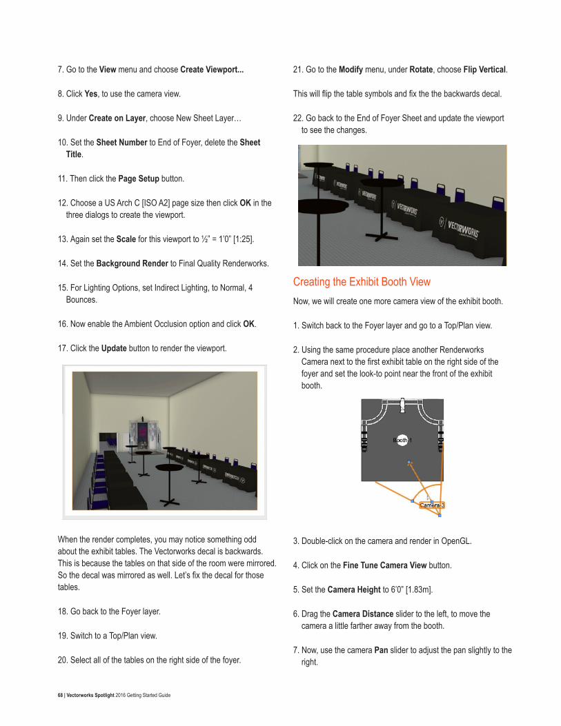
68 | Vectorworks Spotlight 2016 Getting Started Guide
7. Go to the View menu and choose Create Viewport...
8. Click Yes, to use the camera view.
9. Under Create on Layer, choose New Sheet Layer…
10. Set the Sheet Number to End of Foyer, delete the Sheet Title.
11. Then click the Page Setup button.
12. Choose a US Arch C [ISO A2] page size then click OK in the three dialogs to create the viewport.
13. Again set the Scale for this viewport to ½” = 1’0” [1:25].
14. Set the Background Render to Final Quality Renderworks.
15. For Lighting Options, set Indirect Lighting, to Normal, 4 Bounces.
16. Now enable the Ambient Occlusion option and click OK.
17. Click the Update button to render the viewport.
When the render completes, you may notice something odd about the exhibit tables. The Vectorworks decal is backwards. This is because the tables on that side of the room were mirrored. So the decal was mirrored as well. Let’s fix the decal for those tables.
18. Go back to the Foyer layer.
19. Switch to a Top/Plan view.
20. Select all of the tables on the right side of the foyer.
21. Go to the Modify menu, under Rotate, choose Flip Vertical.
This will flip the table symbols and fix the the backwards decal.
22. Go back to the End of Foyer Sheet and update the viewport to see the changes.
Creating the Exhibit Booth ViewNow, we will create one more camera view of the exhibit booth.
1. Switch back to the Foyer layer and go to a Top/Plan view.
2. Using the same procedure place another Renderworks Camera next to the first exhibit table on the right side of the foyer and set the look-to point near the front of the exhibit booth.
3. Double-click on the camera and render in OpenGL.
4. Click on the Fine Tune Camera View button.
5. Set the Camera Height to 6’0” [1.83m].
6. Drag the Camera Distance slider to the left, to move the camera a little farther away from the booth.
7. Now, use the camera Pan slider to adjust the pan slightly to the right.
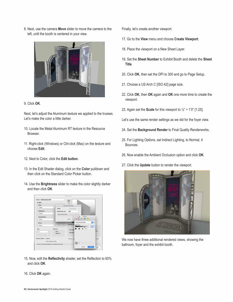
69 | Vectorworks Spotlight 2016 Getting Started Guide
8. Next, use the camera Move slider to move the camera to the left, until the booth is centered in your view.
9. Click OK.
Next, let’s adjust the Aluminum texture we applied to the trusses. Let’s make the color a little darker.
10. Locate the Metal Aluminum RT texture in the Resource Browser.
11. Right-click (Windows) or Ctrl-click (Mac) on the texture and choose Edit.
12. Next to Color, click the Edit button.
13. In the Edit Shader dialog, click on the Color pulldown and then click on the Standard Color Picker button.
14. Use the Brightness slider to make the color slightly darker and then click OK.
15. Now, edit the Reflectivity shader, set the Reflection to 60% and click OK.
16. Click OK again.
Finally, let’s create another viewport.
17. Go to the View menu and choose Create Viewport.
18. Place the viewport on a New Sheet Layer.
19. Set the Sheet Number to Exhibit Booth and delete the Sheet Title.
20. Click OK, then set the DPI to 300 and go to Page Setup.
21. Choose a US Arch C [ISO A2] page size.
22. Click OK, then OK again and OK one more time to create the viewport.
23. Again set the Scale for this viewport to ½” = 1’0” [1:25].
Let’s use the same render settings as we did for the foyer view.
24. Set the Background Render to Final Quality Renderworks.
25. For Lighting Options, set Indirect Lighting, to Normal, 4 Bounces.
26. Now enable the Ambient Occlusion option and click OK.
27. Click the Update button to render the viewport.
We now have three additional rendered views, showing the ballroom, foyer and the exhibit booth.