Embed Size (px)
Citation preview
Part of Thermo Fisher Scientific
LevelPROContinuous Gamma Level SystemInstallation GuideP/N 717760
Revision H


LevelPROContinuous Gamma Level SystemInstallation GuideP/N 717760
Revision H


© 2011 Thermo Fisher Scientific Inc. All rights reserved.
“HART” is a registered trademark of the HART Communication Foundation.
“FOUNDATION fieldbus” and “Fieldbus Foundation” are registered trademarks of Fieldbus Foundation.
“National Instruments” is a registered trademark of National Instruments Corporation.
All other trademarks are the property of Thermo Fisher Scientific Inc. and its subsidiaries.
Thermo Fisher Scientific Inc. (Thermo Fisher) makes every effort to ensure the accuracy and completeness of this manual. However, we cannot be responsible for errors, omissions, or any loss of data as the result of errors or omissions. Thermo Fisher reserves the right to make changes to the manual or improvements to the product at any time without notice.
The material in this manual is proprietary and cannot be reproduced in any form without expressed written consent from Thermo Fisher.

This page intentionally left blank.
Thermo Fisher Scientific LevelPRO Installation Guide v
Revision History
Revision Level Date Comments
1.0 03-1999 Initial release.
2.0 08-2001 Revised per ECO 7570.
A 02-2006 Revised per ECO 5101.
B 10-2007 Revised per ECO 6000.
C 08-2008 Revised per ECO 6540.
D 06-2009 Revised per ECO 6940.
E 04-2010 Revised per ECO 7323.
F 07-2010 Revised per ECO 7430.
G 09-2010 Revised per ECO 7508.
H 12-2011 Revised per ECO 7875.

This page intentionally left blank.
Thermo Fisher Scientific LevelPRO Installation Guide vii
Contents Safety Information & Guidelines ..................................................................... ix
Safety Considerations ............................................................................. ix Warnings, Cautions, & Notes ................................................................ ix
Product Overview ............................................................................................. 1-1 Required Documentation .................................................................... 1-1
Handling & Storage .......................................................................................... 2-1 ESD Procedures .................................................................................. 2-1 Unpacking, Inspection, & Storage ...................................................... 2-2 Packing, Shipping, Transporting, & Receiving .................................... 2-2
Hardware Installation ...................................................................................... 3-1 Licensing ............................................................................................. 3-1 Source-Detector Configurations .......................................................... 3-2 Guidelines ........................................................................................... 3-2
General ............................................................................................ 3-3 System Power Requirements ............................................................ 3-3 Protective Earth Grounding ............................................................. 3-3 Safety Disconnecting Means Requirements ...................................... 3-4
Detector-Transmitter .......................................................................... 3-4 Alignment ........................................................................................ 3-5 Measurable Range ............................................................................ 3-6
Top of Range ................................................................................ 3-6 Bottom of Range ........................................................................... 3-6
The Source Housing ........................................................................... 3-9 Fan Beam Source Guidelines ............................................................ 3-9 Strip Source Guidelines .................................................................. 3-10 Shutter Actuator ............................................................................. 3-10
Multiple Detectors / Source Housings ............................................... 3-11
Wiring .................................................................................................................. 4-1 Overview ............................................................................................. 4-1 Preparation.......................................................................................... 4-1
Wiring Drawings ............................................................................. 4-2 General Procedure ............................................................................... 4-2 The CPU Board .................................................................................. 4-3
System Configuration ...................................................................... 4-4
Chapter 1
Chapter 2
Chapter 3
Chapter 4
Contents
viii LevelPRO Installation Guide Thermo Fisher Scientific
Power Supply ...................................................................................... 4-5 DC Power ........................................................................................ 4-5 Optional AC Power ......................................................................... 4-6
Relays ............................................................................................ 4-6 Serial Communications ....................................................................... 4-7
RS485 Wiring .................................................................................. 4-7 Initial Setup for Party-Line Communications ................................ 4-7
RS232 Wiring .................................................................................. 4-8 Using Serial Communications .......................................................... 4-8
HART Communications ..................................................................... 4-8 FOUNDATION Fieldbus Communications ........................................... 4-9 Contact Closure Inputs ....................................................................... 4-9 Current Output .................................................................................. 4-9
Isolated, Loop Powered Configuration ........................................... 4-10 Non-Isolated, Self-Powered Configuration ..................................... 4-10 Isolated, Self-Powered Configuration ............................................. 4-10
Cascade Mode Wiring ....................................................................... 4-11 Auxiliary Input Wiring ...................................................................... 4-11
Service & Support ............................................................................................. 5-1 Getting Help ....................................................................................... 5-1 Warranty ............................................................................................. 5-2
Ordering Information ....................................................................................... A-1
Specifications ................................................................................................... B-1
Drawings ............................................................................................................ C-1
Replacing the CPU PROM & HART PROM ................................................... D-1 Purpose .............................................................................................. D-1 Procedure ........................................................................................... D-1
CE-EMC Protection Installation Procedure ................................................ E-1 Purpose ............................................................................................... E-1 Procedure ............................................................................................ E-1 Installation .......................................................................................... E-3 AC Power Supply Replacement ........................................................... E-5 Wiring ................................................................................................ E-6
Related Technical Bulletins ........................................................................... F-1
Index .......................................................................................................... INDEX-1
Chapter 5
Appendix A
Appendix B
Appendix C
Appendix D
Appendix E
Appendix F

Thermo Fisher Scientific LevelPRO Installation Guide ix
Safety Information & Guidelines
This section contains information that must be read and understood by all persons installing, using, or maintaining this equipment.
Failure to follow appropriate safety procedures or inappropriate use of the equipment described in this manual can lead to equipment damage or injury to personnel.
Any person working with or on the equipment described in this manual is required to evaluate all functions and operations for potential safety hazards before commencing work. Appropriate precautions must be taken as necessary to prevent potential damage to equipment or injury to personnel.
The information in this manual is designed to aid personnel to correctly and safely install, operate, and / or maintain the system described; however, personnel are still responsible for considering all actions and procedures for potential hazards or conditions that may not have been anticipated in the written procedures. If a procedure cannot be performed safely, it must not be performed until appropriate actions can be taken to ensure the safety of the equipment and personnel. The procedures in this manual are not designed to replace or supersede required or common sense safety practices. All safety warnings listed in any documentation applicable to equipment and parts used in or with the system described in this manual must be read and understood prior to working on or with any part of the system.
Failure to correctly perform the instructions and procedures in this manual or other documents pertaining to this system can result in equipment malfunction, equipment damage, and / or injury to personnel.
Warnings, cautions, and notes are used throughout this manual to alert users to potential hazards or important information. Failure to heed the warnings and cautions in this manual can lead to injury or equipment damage.
Warning Warnings notify users of procedures, practices, conditions, etc. which may result in injury or death if not carefully observed or followed. The triangular icon displayed with a warning varies depending on the type of hazard (general, electrical, radiation).
Safety Considerations
Warnings, Cautions, &
Notes
Safety Information & Guidelines Warnings, Cautions, & Notes
x LevelPRO Installation Guide Thermo Fisher Scientific
Caution Cautions notify users of operating procedures, practices, conditions, etc. which may result in equipment damage if not carefully observed or followed.
Note Notes emphasize important or essential information or a statement of company policy regarding an operating procedure, practice, condition, etc.
Thermo Fisher Scientific LevelPRO Installation Guide 1-1
Chapter 1 Product Overview
Refer to the LevelPRO user guide for descriptions of instrument functions and features.
In addition to this guide, the following documents must be read and understood by all persons installing, using, or maintaining this equipment:
LevelPRO user guide, p/n 717778
LevelPRO HART operation guide, p/n 717817 (if using HART)
Model 9734 HHT user guide, p/n 717797 (if using the HHT)
Gamma Radiation Safety Guide, p/n 717904
LevelPRO with FOUNDATION™ Fieldbus Application Guide, p/n 717915 (if FOUNDATION fieldbus option is installed)
Required Documentation

This page intentionally left blank.
Thermo Fisher Scientific LevelPRO Installation Guide 2-1
Chapter 2 Handling & Storage
This chapter addresses procedures for handling electrostatic discharge (ESD) sensitive equipment, as well as procedures for unpacking, inspecting, and storing of the system.
Caution This system is an ESD sensitive instrument. Use proper ESD protective equipment and procedures. Failure to comply with ESD procedures can result in circuit damage.
The instrument contains electronic components that can be damaged from discharges of static electricity: Do not touch the circuit board components. Ordinarily, handling the circuit boards by their edges will not damage the circuits.
Observe the following when installing, setting up, servicing, troubleshooting, or repairing the instrument:
1. Use an antistatic bag. Most instrument subassemblies are shipped in a special antistatic bag. When not installed, keep the assembly in the bag as often as possible.
2. Remove ESD sensitive subassemblies only under the following conditions:
a. When at a designated static-free workstation or when the bag is grounded at a field site.
b. After the conductive area of the container has been neutralized.
c. After making firm contact with an antistatic mat and / or firmly gripping a grounded individual.
3. Personnel handling ESD sensitive devices should be neutralized to a static-free workstation by means of a grounding wrist strap that is connected to the station or to a good grounding point at the field site.
4. Do not allow clothing to make contact with ESD sensitive devices.
ESD Procedures
Handling & Storage Unpacking, Inspection, & Storage
2-2 LevelPRO Installation Guide Thermo Fisher Scientific
5. Avoid touching edge connectors and components.
6. Avoid partially connecting ESD sensitive devices. These devices, especially the power supply connector, can be damaged by floating leads.
7. Ground test equipment.
8. Avoid static charges during troubleshooting.
Note Inspection, adjustment, installation, and maintenance of the instrument must be performed by experienced personnel only.
1. Upon receipt, inspect the instrument for damage that may have occurred while in transit. If there is evidence of rough handling or damage, file a damage claim with the transportation company immediately. Notify Thermo Fisher Scientific and / or your sales representative as soon as possible.
2. Carefully inspect the packing material prior to discarding it to ensure that all equipment and instruction paperwork has been removed.
3. Use the original packing material and container for storage if necessary.
4. If storing the instrument, the storage environment should be protected, free from extremes of temperatures and high humidity, and fall within the environmental constraints listed in the specifications.
All personnel involved in the packing, shipping, or receiving of hazardous material must be trained in accordance with the United States Department of Transportation (DOT) and OSHA hazardous materials regulations or in accordance with the Canadian Nuclear Safety Commission (CNSC) regulations.
Unpacking, Inspection, & Storage
Packing, Shipping, Transporting, &
Receiving
Thermo Fisher Scientific LevelPRO Installation Guide 3-1
Chapter 3 Hardware Installation
Read the Gamma Radiation Safety Guide (p/n 717904) PRIOR TO installing the equipment.
Note Copies of the drawings referenced in this manual are provided in Appendix C.
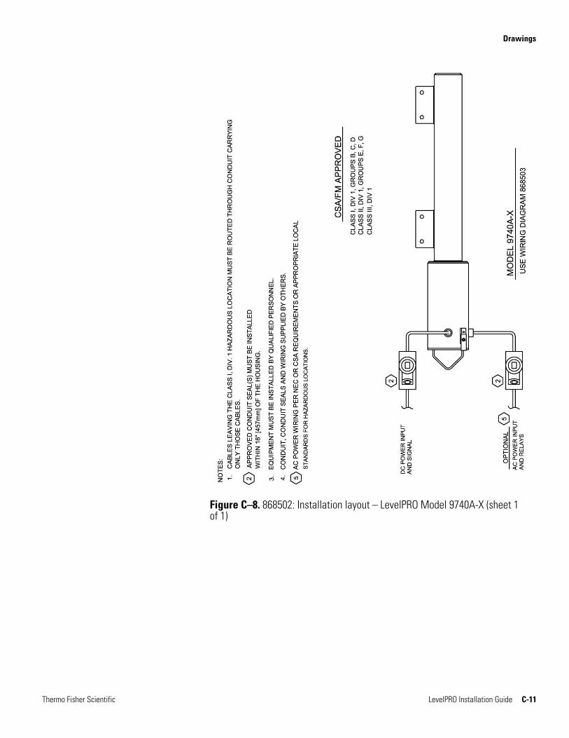
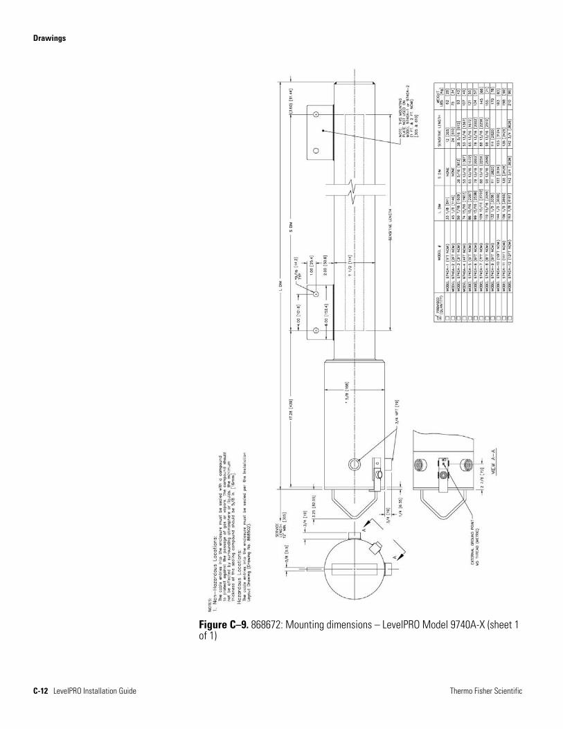
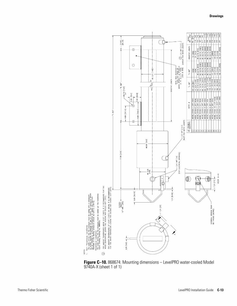
For detector-transmitter housing layout details, refer to drawing 868502. For mounting dimensions, refer to drawing 868672 or 868674 for water-cooled units.
A variety of source housings are used with the scintillation detector depending on the requirements of the application. Refer to the appropriate drawing for your source.
Warning The instrument is a nuclear device regulated by federal and / or state authorities. You are responsible for knowing and following the pertinent safety and regulatory requirements. Refer to the Gamma Radiation Safety Guide (p/n 717904) for a summary of these requirements.
Warning Moving or removing an installed source housing or any assembly that includes a source housing requires a person who is specifically licensed to install and commission Thermo Scientific source housings.
In the United States, your general license permits you to own and install all of the instrument’s components, including the source housing. However, you may not commission the instrument (remove the lock and open the source housing shutter for the first time) without a specific license authorizing radiation commissioning of the instrument. In Canada, you are only allowed to remove the instrument from the shipping container if your CNSC license has a condition authorizing mounting / dismounting of devices. For assistance obtaining a license and / or commissioning / decommissioning the instrument, contact Thermo Fisher Scientific.
Licensing
Hardware Installation Source-Detector Configurations
3-2 LevelPRO Installation Guide Thermo Fisher Scientific
The gauge is comprised of a source housing that contains the radioisotope source and the detector-transmitter that contains the scintillation detector and electronics. Sources are available in a fan beam or strip source configuration. For most fan beams, the beam angle spreads at a 45° angle in the vertical dimensions. A 30° beam angle spread is available with model 5210, and 60° beam angle spreads are available with models 5205B, 5206B, 5207B, and 5208B.
Strips sources emit radiation evenly along the length of the vessel from the source and measure the radiation level reaching the detector after passing through the vessel walls and the process material.
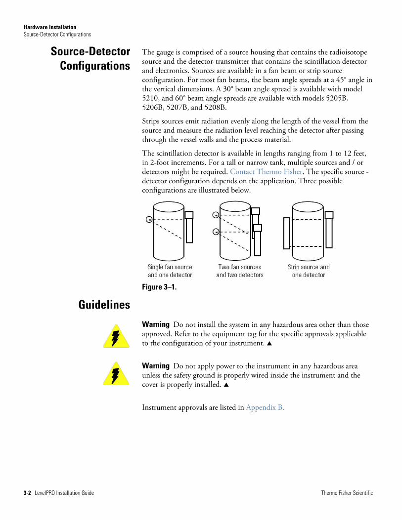
The scintillation detector is available in lengths ranging from 1 to 12 feet, in 2-foot increments. For a tall or narrow tank, multiple sources and / or detectors might be required. Contact Thermo Fisher. The specific source -detector configuration depends on the application. Three possible configurations are illustrated below.
Figure 3–1.
Warning Do not install the system in any hazardous area other than those approved. Refer to the equipment tag for the specific approvals applicable to the configuration of your instrument.
Warning Do not apply power to the instrument in any hazardous area unless the safety ground is properly wired inside the instrument and the cover is properly installed.
Instrument approvals are listed in Appendix B.
Source-Detector Configurations
Guidelines

Hardware Installation Guidelines
Thermo Fisher Scientific LevelPRO Installation Guide 3-3
Review the following guidelines when planning gauge installation:
1. Correct power source is available. See “Power Requirements” later in this chapter.
2. You will need to supply the necessary brackets and hardware required for mounting the gauge to the vessel.
3. Operating temperature range: -40°C to +60°C (-40°F to +140°F).
4. There should be enough clearance to install and service the source housing and the detector. Refer to the appropriate dimensional drawings in the drawing appendix.
5. Position the source housing so the radioactive source identification tag is visible. Mount it so the tag is upright.
6. The gauge should not be mounted where process overflow or other material can collect in the beam path. The source housing shutter mechanism must be kept free of debris.
7. If the handheld terminal will be used for configuration, the connection must be located in a safe area.
Ensure the correct power source is available. One of the following input power sources is required: 24 Vdc ± 20% or 115/230 Vac ± 15%, 50/60 Hz (requires optional AC power board). The maximum power requirement is 12 VA. Both DC and AC power may be supplied to the gauge at the same time. The gauge will draw power from whichever input source provides the higher DC source voltage.
The LevelPRO enclosure provides internal safety ground and external safety ground lugs (reference drawing 868503) for Safety Protective Earth Grounding. The external safety ground lug is used to connect the unit to Earth Ground. The internal safety ground lug is used to connect the AC power input ground line.
General
System Power Requirements
Protective Earth Grounding
Hardware Installation Detector-Transmitter
3-4 LevelPRO Installation Guide Thermo Fisher Scientific
As a permanently connected equipment, the LevelPRO gauge requires a switch or circuit breaker as the means for disconnection. The customer needs to prepare the switch or circuit breaker according to the following requirements:
1. A switch or circuit breaker must be included in the building installation.
2. It must be in close proximity to the equipment (LevelPRO) and within easy reach of the operator.
3. It must be marked as the disconnecting device for this equipment (LevelPRO).
Warning Do not install the system in any hazardous area other than those approved. Refer to the equipment tag for the specific approvals applicable to the configuration of your instrument.
Warning Do not apply power to the instrument in any hazardous area unless the safety ground is properly wired inside the instrument and the cover is properly installed.
Warning For hazardous location installations, the cable entries must be sealed per the installation layout drawing (868502).
Warning For non-hazardous location installations, the enclosure cable entries must be sealed with a compound to protect against the passage of gas or vapors. The sealing compound should not be affected by the surrounding atmosphere or liquids. The sealing compound must have a thickness of at least 5/8 inch (16 mm).
Warning Use proper lifting procedures during installation to avoid injury. Refer to drawings 868672 or 868674 (water-cooled units) for weights and dimensions of the detector housing.
Safety Disconnecting
Means Requirements
Detector-Transmitter
Hardware Installation Detector-Transmitter
Thermo Fisher Scientific LevelPRO Installation Guide 3-5
Refer to drawings 868502 and 868672 (868674 for water-cooled units) for mounting dimensions of the detector-transmitter.
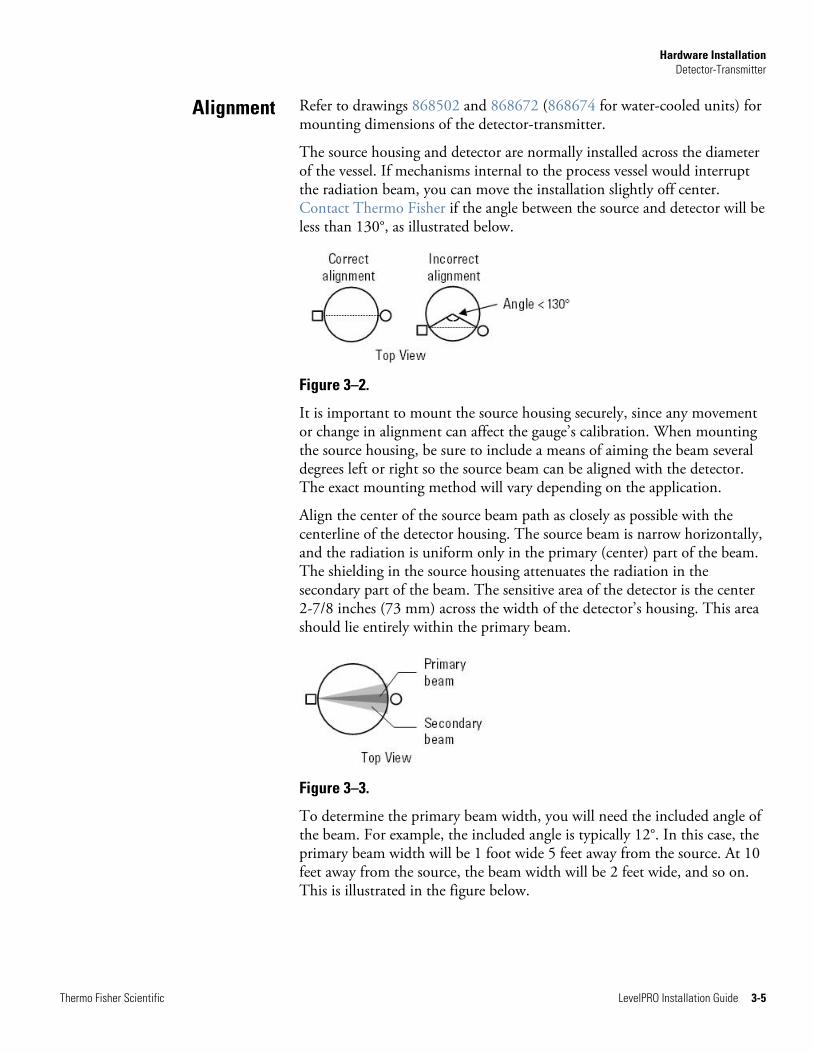
The source housing and detector are normally installed across the diameter of the vessel. If mechanisms internal to the process vessel would interrupt the radiation beam, you can move the installation slightly off center. Contact Thermo Fisher if the angle between the source and detector will be less than 130°, as illustrated below.
Figure 3–2.
It is important to mount the source housing securely, since any movement or change in alignment can affect the gauge’s calibration. When mounting the source housing, be sure to include a means of aiming the beam several degrees left or right so the source beam can be aligned with the detector. The exact mounting method will vary depending on the application.
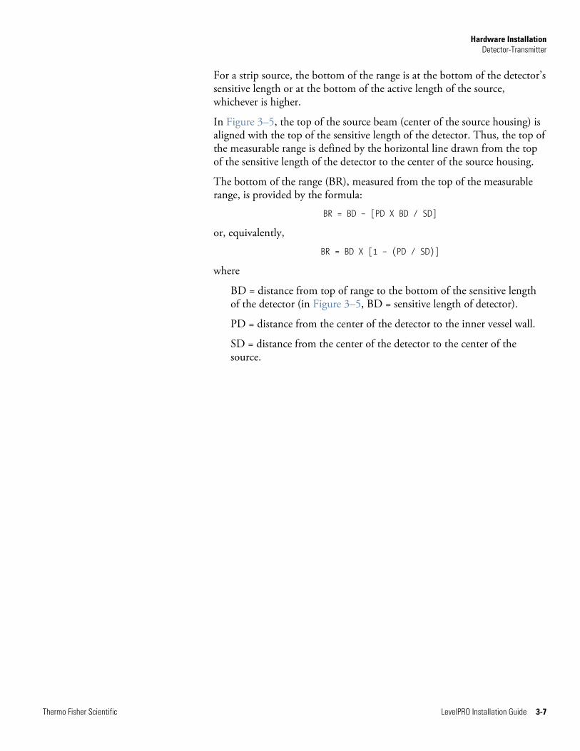
Align the center of the source beam path as closely as possible with the centerline of the detector housing. The source beam is narrow horizontally, and the radiation is uniform only in the primary (center) part of the beam. The shielding in the source housing attenuates the radiation in the secondary part of the beam. The sensitive area of the detector is the center 2-7/8 inches (73 mm) across the width of the detector’s housing. This area should lie entirely within the primary beam.
Figure 3–3.
To determine the primary beam width, you will need the included angle of the beam. For example, the included angle is typically 12°. In this case, the primary beam width will be 1 foot wide 5 feet away from the source. At 10 feet away from the source, the beam width will be 2 feet wide, and so on. This is illustrated in the figure below.
Alignment

Hardware Installation Detector-Transmitter
3-6 LevelPRO Installation Guide Thermo Fisher Scientific
Figure 3–4. Determining primary beam width
Before beginning the installation, verify that the measurable range (the range over which the process level can be measured) of the proposed installation meets the requirements of your application. The top and bottom of the measurement range depend on the source type (fan or strip), the detector length, and the position of the source relative to the detector’s sensitive length. Sensitive length refers to the part of the detector that senses radiation.
Note The sensitive length of the detector is approximately the length from the upper mounting bolt to the lower mounting bolt.
For a source with a fan beam, the top of the range is at the top of the sensitive length of the detector or at the center of the source housing, whichever is lower.
For a strip source, the top of the range is at the top of the sensitive length of the detector or at the top of the active length of the source, whichever is lower.
For a source with a fan beam, the bottom of range is the point where a line drawn from the source to the detector centerline at the bottom end of the detector’s sensitive length intersects the inner vessel wall nearest the detector. This is illustrated in Figure 3–5.
Note If the vertical beam width of the source does not fully illuminate the sensitive length of the detector, the bottom of the range is the point at which the lower limit of the source beam intersects the inner vessel wall.
Measurable Range
Top of Range
Bottom of Range
Hardware Installation Detector-Transmitter
Thermo Fisher Scientific LevelPRO Installation Guide 3-7
For a strip source, the bottom of the range is at the bottom of the detector’s sensitive length or at the bottom of the active length of the source, whichever is higher.
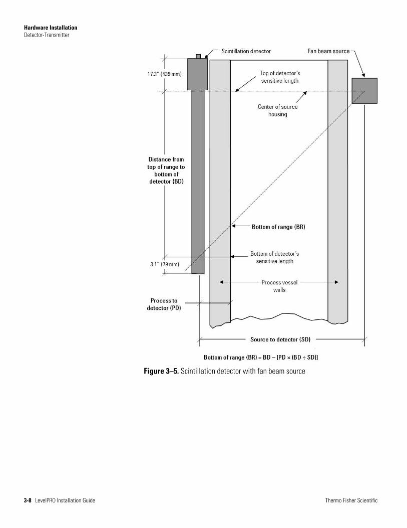
In Figure 3–5, the top of the source beam (center of the source housing) is aligned with the top of the sensitive length of the detector. Thus, the top of the measurable range is defined by the horizontal line drawn from the top of the sensitive length of the detector to the center of the source housing.
The bottom of the range (BR), measured from the top of the measurable range, is provided by the formula:
BR = BD – [PD X BD / SD]
or, equivalently,
BR = BD X [1 – (PD / SD)]
where
BD = distance from top of range to the bottom of the sensitive length of the detector (in Figure 3–5, BD = sensitive length of detector).
PD = distance from the center of the detector to the inner vessel wall.
SD = distance from the center of the detector to the center of the source.
Hardware Installation Detector-Transmitter
3-8 LevelPRO Installation Guide Thermo Fisher Scientific
Figure 3–5. Scintillation detector with fan beam source
Hardware Installation The Source Housing
Thermo Fisher Scientific LevelPRO Installation Guide 3-9
Warning In the United States, you may uncrate and mount the source housing, but you may not remove the shipping bolt unless you are licensed to commission the gauge. In Canada, you must have a license condition permitting mounting / dismounting, and without this condition, users may not remove the source from the shipping crate.
Warning Use proper lifting procedures to avoid injury.
The scintillation detector can be used with either a fan beam source or a strip source. Normally the scintillation detector is mounted so that the top of the detector’s sensitive length is even with the top of the fan beam or even with the top of the active length of the strip source.
Note the following if using a source with a fan beam.
1. The vertical angle of the fan beam is typically 45°. This means that the beam’s vertical range is equal to the horizontal distance between the detector and the source. (In special cases, the angle may be 30° or 60°. Contact Thermo Fisher for guidance.)
2. Mount the source housing so that the top of the fan beam is aligned with the top of the sensitive length of the detector.
3. Install the source housing with its mounting face as close to the process vessel as practical, with no structural material (mounting tabs, brackets, etc.) between the beam area and the vessel.
4. The mounting should ensure accurate beam alignment with the detector and provide for easy left-right angular adjustment. The top of the beam should be even with the top of the measurable range.
The Source Housing
Fan Beam Source Guidelines
Hardware Installation The Source Housing
3-10 LevelPRO Installation Guide Thermo Fisher Scientific
Note the following if using a strip source.
1. Refer to the source housing drawings to determine the position of the active length of the strip source and other mounting dimensions.
2. Secure the housing with the 1/2-inch (12 mm) bolts and lock washers (six places). The housing mounting face allows clearance for bolts or studs extending up to 2-1/4 inches (57 mm) from the mounting surface.
3. For best results, the measurable range should be less than the active length of the strip source(s). Position the strip source so that the bottom of the active length of the source is even with the minimum level to be measured. If the measurable range must be greater than the active length of the strip source, position the top of the active length of the source so that it is even with the maximum level to be measured.
4. The mounting surface should be vertical. The mounting should ensure accurate beam alignment with the detector and provide for easy left-right angular adjustment.
5. Install the source housing with its mounting face as close to the vessel as practical, with no structural material (mounting tabs, brackets, etc.) between the beam area and the vessel.
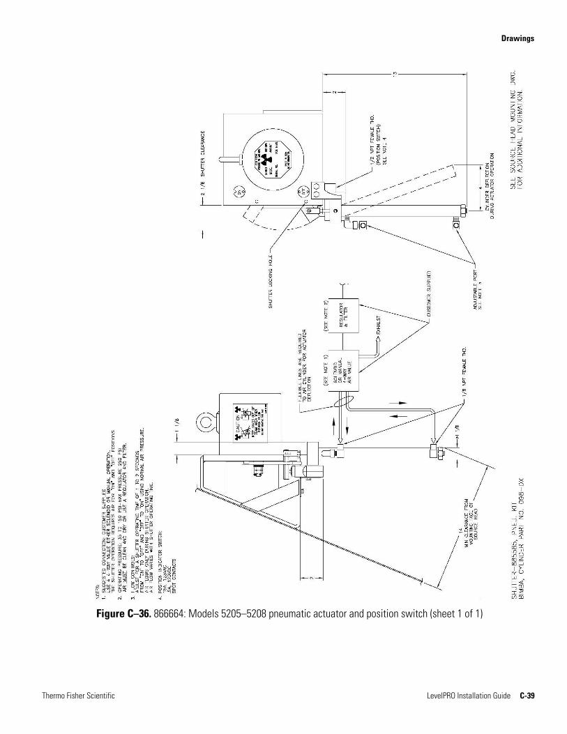
If your source housing includes a pneumatic shutter actuator, refer to drawing 866664 for installation details.
Strip Source Guidelines
Shutter Actuator
Hardware Installation Multiple Detectors / Source Housings
Thermo Fisher Scientific LevelPRO Installation Guide 3-11
Certain applications may require the use of multiple detectors and / or multiple source housings to span the desired measurable range.
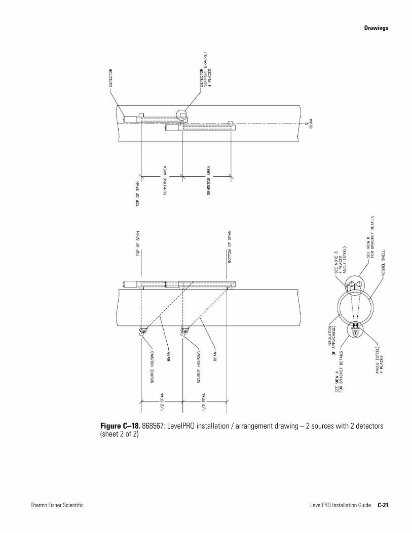
If multiple detectors are used, the uppermost unit should be mounted so that the top of its sensitive length is even with the top of the measurable range. The remaining units should be mounted so that the top of each detector’s sensitive length is aligned with or slightly overlaps the bottom of the sensitive length of the detector mounted just above it.
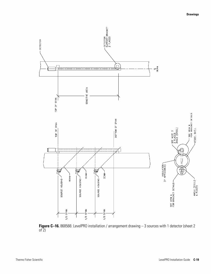
If more than one source housing is required, the top source housing should be installed with the top of its beam even with the top of the desired measurable range. The other source housings should be spaced evenly along the vertical dimension of the vessel. For example, if the range of interest is 12 feet and three fan beam sources are used, the source housings should be spaced four feet apart.
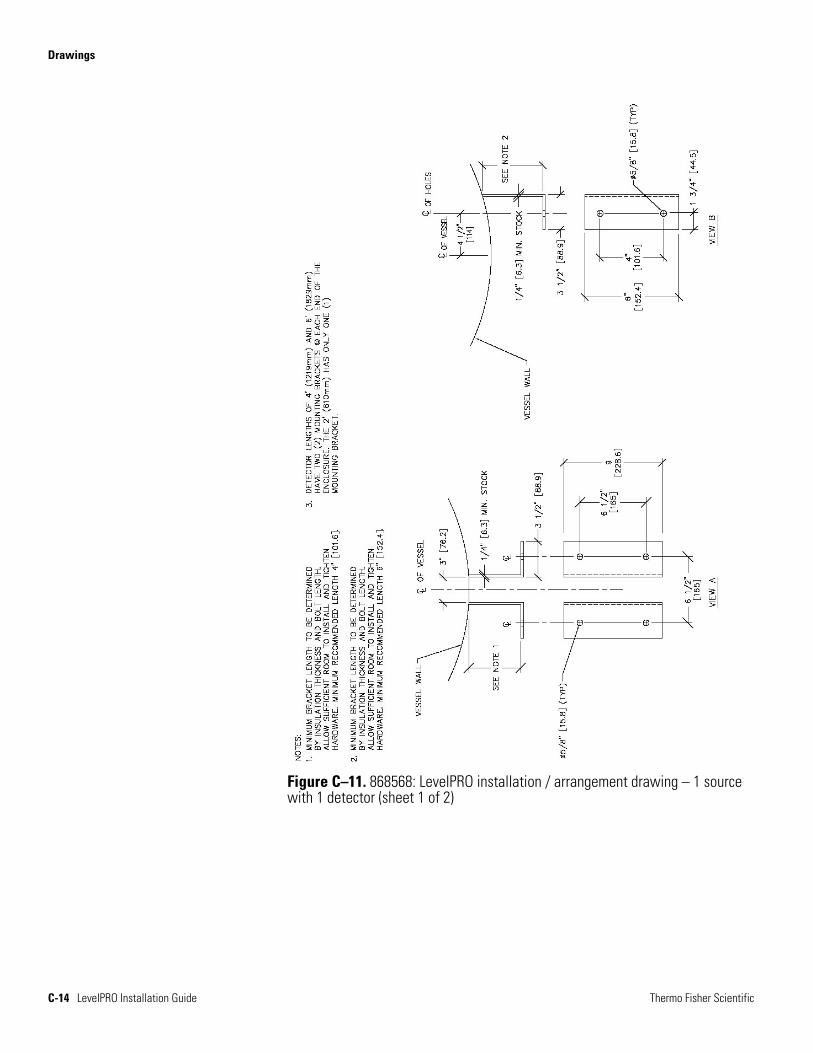
The installation / arrangement drawings provide mounting dimensions for several configurations (refer to drawings 868566 through 868571).
When mounting two or more pairs of strip sources and detectors on a small diameter tank, adjacent pairs of source housings and detectors may be rotated by 90° if necessary. The source housing and detector for each source-detector pair at the same height must still be mounted on opposite sides of the tank (180°). After mounting the uppermost source-detector pair, the position of the source housing and detector in the next lower pair may be rotated by 90° and so on.
Multiple Detectors /
Source Housings

This page intentionally left blank.
Thermo Fisher Scientific LevelPRO Installation Guide 4-1
Chapter 4 Wiring
Wiring should be performed in the following order:
1. Power to the gauge
2. Remote computer terminal or HHT to the gauge via the serial communication ports
3. Optional wiring:
a. 4–20 mA current output
b. Relay contacts
c. Contact closure inputs
d. Remote display
e. Auxiliary 4–20 mA current input
f. Wiring to cascade multiple units
Review the following carefully prior to connecting any wiring.
Warning Remove all power from the unit before making any connections. Electrocution can result if power is present.
Warning All wiring must be done by qualified individuals in accordance with applicable codes such as the NEC (National Electric Code) ANSI / NFPA 70 specifications or the Canadian Electrical Code Part 1.
Warning Do not apply power to the unit in any hazardous area unless the safety ground is properly wired inside the unit and the cover is properly installed.
Warning For hazardous location installations, the cable entries must be sealed per the installation layout drawing (868502).
Overview
Preparation
Wiring General Procedure
4-2 LevelPRO Installation Guide Thermo Fisher Scientific
Warning For non-hazardous location installations, the cable entries into the enclosure must be sealed with a compound to protect against the passage of gas or vapors. The sealing compound should not be affected by the surrounding atmosphere or liquids. The sealing compound must have a thickness of at least 5/8 inch (16 mm).
Warning If metal conduit is used, the conduit must be grounded.
Warning Connect the AC wiring earth ground to the internal safety ground terminal, as shown in the wiring diagram. Refer to “Optional AC Power” later in this chapter to change the AC supply voltage.
The installation layout drawing (868502) provides general guidance for routing the cables to the unit. The installation wiring drawing (868503) shows the function of each connector pin on the CPU board and optional AC power / relay board. In addition, the drawing shows cable requirements for connecting the sensor to the transmitter, power requirements, and grounding locations.
The label on the top of the detector-transmitter chassis also shows connector pin information for wiring the power boards, including the relay contacts, the contact closure inputs, and the current output. Drawing 868519 provides additional instructions for wiring the RS485 and RS232 serial port connectors.
Follow this general procedure to access the detector electronics for wiring.
1. Ensure all source housing shutters are in the OFF position.
2. Ensure all power to the gauge is turned off.
3. Remove the housing access cover by loosening the screw on the cover retaining bracket and sliding the bracket off of the housing cover. Unscrew the housing access cover. Two lugs on the top of the cover aid with removal.
Wiring Drawings
General Procedure

Wiring The CPU Board
Thermo Fisher Scientific LevelPRO Installation Guide 4-3
4. Remove the cable conduit plugs from the hole(s) that will be used. As shown in the installation layout drawing (868502), lay one conduit for the DC power input and signal cables and a second conduit for the AC power input and relays, if applicable. Route the cables into the detector housing and connect input power and signal wires as shown in the wiring drawing (868503).
5. The ground line of the AC input power needs to be connected to the internal safety ground lug of the LevelPRO housing.
6. When DC input power is used, it is imperative that an Earth Ground be connected to either the internal or external safety ground lug of the LevelPRO housing.
7. Pull each cable through the correct conduit fitting and into the enclosure. Leave approximately 6 inches (150 mm) for strain relief. Secure the conduit, making sure it is completely sealed.
8. Continue through the remaining sections in this chapter for wiring instructions specific to the power supply, serial and HART communications, etc.
9. When the wiring is complete, replace the detector housing cover, and secure the cover retaining bracket.
10. While the mounting hardware of the LevelPRO housing may provide an adequate earth ground, it is recommended that a true earth ground always be connected to the external safety ground lug of the housing.
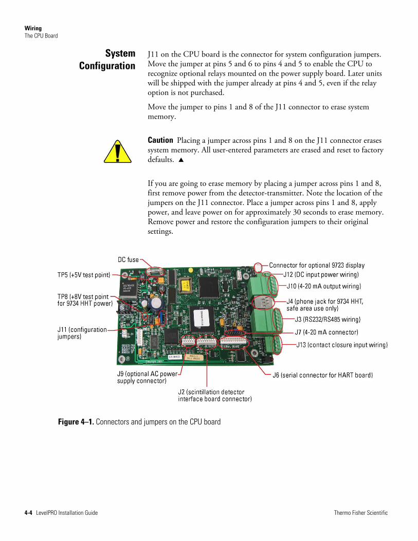
The CPU board is the system’s main board. The gauge is shipped from the factory with all CPU jumpers configured properly for your system configuration. Should you need to replace the CPU board, note the jumper settings for connectors J7 (current output configuration) and J11 (system configuration) before replacing the board. After installing the new board, verify that the jumpers are set properly for your system configuration. Figure 4–1 shows the location of connectors and jumpers.
The CPU Board
Wiring The CPU Board
4-4 LevelPRO Installation Guide Thermo Fisher Scientific
J11 on the CPU board is the connector for system configuration jumpers. Move the jumper at pins 5 and 6 to pins 4 and 5 to enable the CPU to recognize optional relays mounted on the power supply board. Later units will be shipped with the jumper already at pins 4 and 5, even if the relay option is not purchased.
Move the jumper to pins 1 and 8 of the J11 connector to erase system memory.
Caution Placing a jumper across pins 1 and 8 on the J11 connector erases system memory. All user-entered parameters are erased and reset to factory defaults.
If you are going to erase memory by placing a jumper across pins 1 and 8, first remove power from the detector-transmitter. Note the location of the jumpers on the J11 connector. Place a jumper across pins 1 and 8, apply power, and leave power on for approximately 30 seconds to erase memory. Remove power and restore the configuration jumpers to their original settings.
Figure 4–1. Connectors and jumpers on the CPU board
System Configuration
Wiring Power Supply
Thermo Fisher Scientific LevelPRO Installation Guide 4-5
The system is designed to operate on 24 Vdc. If the optional AC power board is installed, the system can also operate on 115 or 230 Vac (± 15%), 50/60 Hz. The maximum input power requirement is 12 VA. If both AC and DC power are supplied to the detector, the detector will draw power from whichever source provides the higher DC voltage.
The maximum length of the cable that can be used to supply power varies depending on the wire gauge. Refer to the wiring drawing (868503) for cable information and other wiring details.
Warning All wiring must be done by qualified individuals in accordance with applicable codes such as the NEC (National Electric Code) ANSI / NFPA 70 specifications or the Canadian Electrical Code Part 1. For intrinsically safe systems, refer to ANSI / ISA RP 12.6.
Note To meet the requirements of CSA 1010.1, an external switch or circuit breaker must be installed to allow the power source to be disconnected from the gauge. In addition, protective bonding (grounding) must always be provided, even if DC power is used.
J12 on the CPU board is the connector for the DC source voltage wiring. Refer to the wiring drawing (868503) and to the table below for connections.
Table 4–1. DC power connections
Power Supply J12 on CPU Board
Positive (+) J12-2
Negative (-) J12-1
Note To meet the requirements of CSA 1010.1, the input DC terminals must be supplied from a SELV (Safety Extra Low Voltage) source.
Power Supply
DC Power
Wiring Power Supply
4-6 LevelPRO Installation Guide Thermo Fisher Scientific
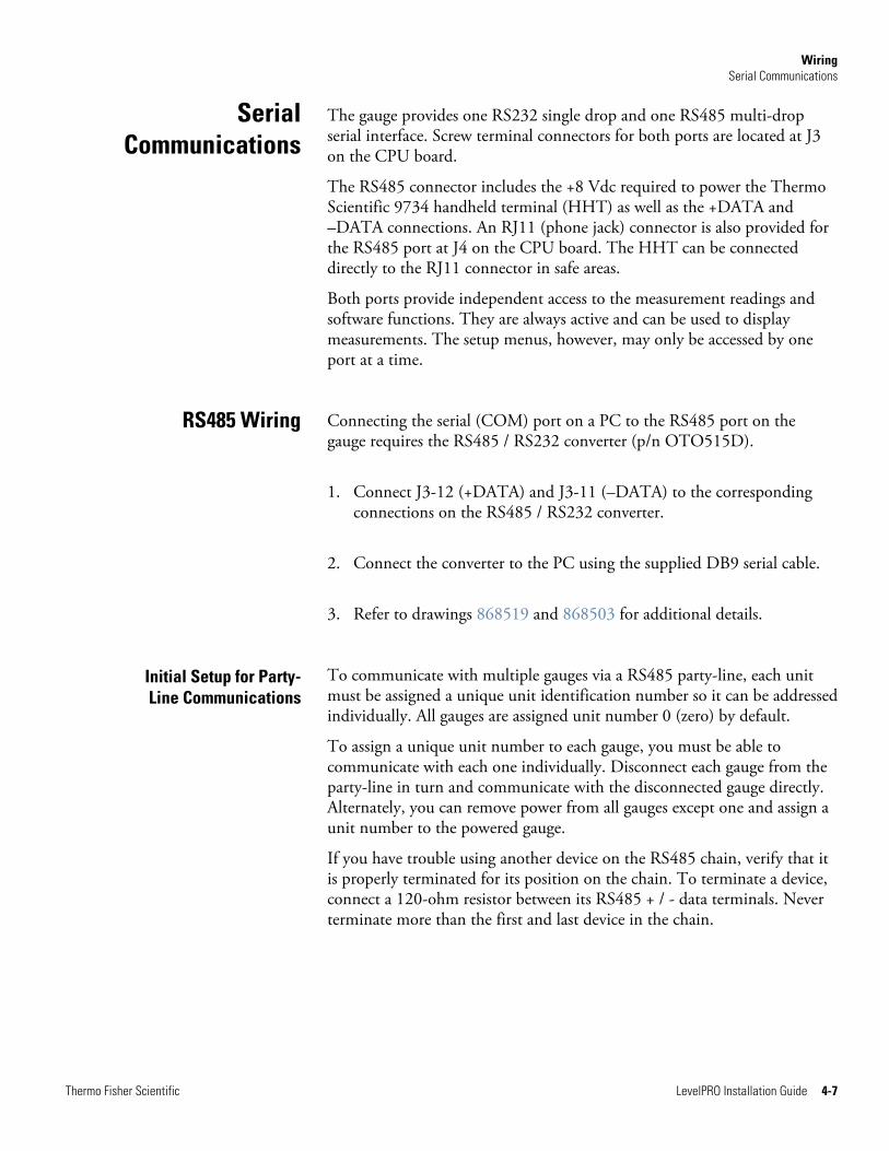
If the optional AC power board is installed, the gauge may be operated using 115 or 230 Vac. The AC selector switch is shown in the figure below.
Caution Applying 230 Vac with the selector switch in the 115 Vac position will damage the equipment.
J9 on the CPU board is the connector for the AC power supply, and J17 on the AC power supply is the wiring connector. Refer to the wiring drawing (868503) and to the figure below.
Figure 4–2. AC power supply board
Caution For reliable operation and to maintain safety approval, the F1 fuse on the AC power board must only be replaced with an approved fuse.
Warning Remove all power from the unit before making any connections. Electrocution can result if power is present.
The AC power supply option can be purchased with two relays. Relay contacts are Form C SPDT, isolated 8 A, 220 Vac. The relays can be configured to open or close on events or faults or with level measurement. Refer to the LevelPRO user manual for instructions.
Refer to the wiring drawing (868503) and the label inside the transmitter cover for wiring details.
Optional AC Power
Relays
Wiring Serial Communications
Thermo Fisher Scientific LevelPRO Installation Guide 4-7
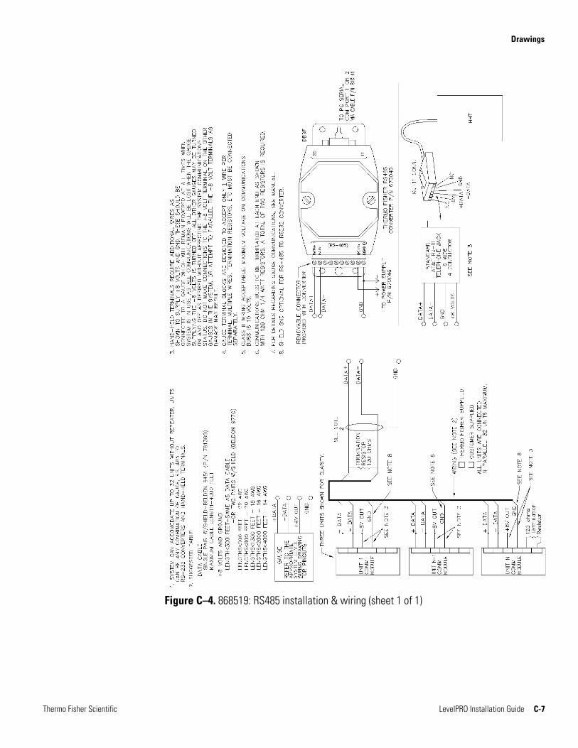
The gauge provides one RS232 single drop and one RS485 multi-drop serial interface. Screw terminal connectors for both ports are located at J3 on the CPU board.
The RS485 connector includes the +8 Vdc required to power the Thermo Scientific 9734 handheld terminal (HHT) as well as the +DATA and –DATA connections. An RJ11 (phone jack) connector is also provided for the RS485 port at J4 on the CPU board. The HHT can be connected directly to the RJ11 connector in safe areas.
Both ports provide independent access to the measurement readings and software functions. They are always active and can be used to display measurements. The setup menus, however, may only be accessed by one port at a time.
Connecting the serial (COM) port on a PC to the RS485 port on the gauge requires the RS485 / RS232 converter (p/n OTO515D).
1. Connect J3-12 (+DATA) and J3-11 (–DATA) to the corresponding connections on the RS485 / RS232 converter.
2. Connect the converter to the PC using the supplied DB9 serial cable.
3. Refer to drawings 868519 and 868503 for additional details.
To communicate with multiple gauges via a RS485 party-line, each unit must be assigned a unique unit identification number so it can be addressed individually. All gauges are assigned unit number 0 (zero) by default.
To assign a unique unit number to each gauge, you must be able to communicate with each one individually. Disconnect each gauge from the party-line in turn and communicate with the disconnected gauge directly. Alternately, you can remove power from all gauges except one and assign a unit number to the powered gauge.
If you have trouble using another device on the RS485 chain, verify that it is properly terminated for its position on the chain. To terminate a device, connect a 120-ohm resistor between its RS485 + / - data terminals. Never terminate more than the first and last device in the chain.
Serial Communications
RS485 Wiring
Initial Setup for Party-Line Communications
Wiring HART Communications
4-8 LevelPRO Installation Guide Thermo Fisher Scientific
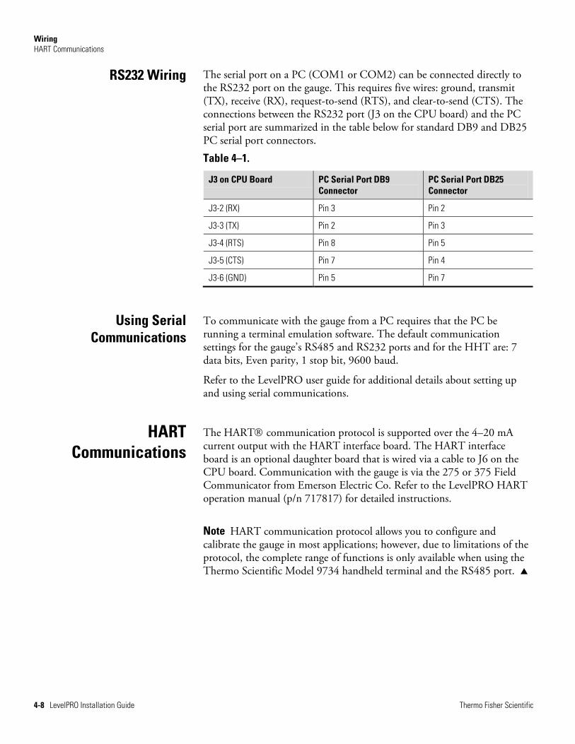
The serial port on a PC (COM1 or COM2) can be connected directly to the RS232 port on the gauge. This requires five wires: ground, transmit (TX), receive (RX), request-to-send (RTS), and clear-to-send (CTS). The connections between the RS232 port (J3 on the CPU board) and the PC serial port are summarized in the table below for standard DB9 and DB25 PC serial port connectors.
Table 4–1.
J3 on CPU Board PC Serial Port DB9 Connector
PC Serial Port DB25 Connector
J3-2 (RX) Pin 3 Pin 2
J3-3 (TX) Pin 2 Pin 3
J3-4 (RTS) Pin 8 Pin 5
J3-5 (CTS) Pin 7 Pin 4
J3-6 (GND) Pin 5 Pin 7
To communicate with the gauge from a PC requires that the PC be running a terminal emulation software. The default communication settings for the gauge’s RS485 and RS232 ports and for the HHT are: 7 data bits, Even parity, 1 stop bit, 9600 baud.
Refer to the LevelPRO user guide for additional details about setting up and using serial communications.
The HART communication protocol is supported over the 4–20 mA current output with the HART interface board. The HART interface board is an optional daughter board that is wired via a cable to J6 on the CPU board. Communication with the gauge is via the 275 or 375 Field Communicator from Emerson Electric Co. Refer to the LevelPRO HART operation manual (p/n 717817) for detailed instructions.
Note HART communication protocol allows you to configure and calibrate the gauge in most applications; however, due to limitations of the protocol, the complete range of functions is only available when using the Thermo Scientific Model 9734 handheld terminal and the RS485 port.
RS232 Wiring
Using Serial Communications
HART Communications
Wiring Foundation Fieldbus Communications
Thermo Fisher Scientific LevelPRO Installation Guide 4-9
With FOUNDATION fieldbus, the gauge provides users with access to control or program parameters via a host system. The fieldbus connector is accessible from the faceplate of the LevelPRO, and the only connections required for operation are to the H1 bus.
Refer to the LevelPRO with FOUNDATION fieldbus application guide for specific wiring instructions.
The contact closure inputs are dry contact inputs between ground and Switch 1 and ground and Switch 2 at J13 on the CPU board. The gauge can be configured via software settings to execute a command or other function upon a user-provided contact opening or closing. Refer to the LevelPRO user manual for instructions on assigning commands to the contact closure inputs.
When operating in “cascade” mode, where multiple units are wired together to act as a single detector, contact closure Switch 2 is dedicated to performing the cascading function. Refer to drawings 868503 and 868529.
Following are the configurations available for the 4–20 mA current output:
Isolated, loop-powered (default)
Non-isolated, self-powered
Isolated, self-powered output (requires optional piggyback board p/n 886595)
The isolated, loop-powered or non-isolated, self-powered configurations can drive an 800 ohm maximum load over the full current output range. The isolated, self-powered current output can drive a maximum load of 1000 ohms. The current output is programmable between 3.8 and 20.5 mA. The fault low condition for the current output is 3.6 mA or less, and the fault high condition is 20.8 mA or greater.
FOUNDATION Fieldbus
Communications
Contact Closure Inputs
Current Output
Wiring Current Output
4-10 LevelPRO Installation Guide Thermo Fisher Scientific
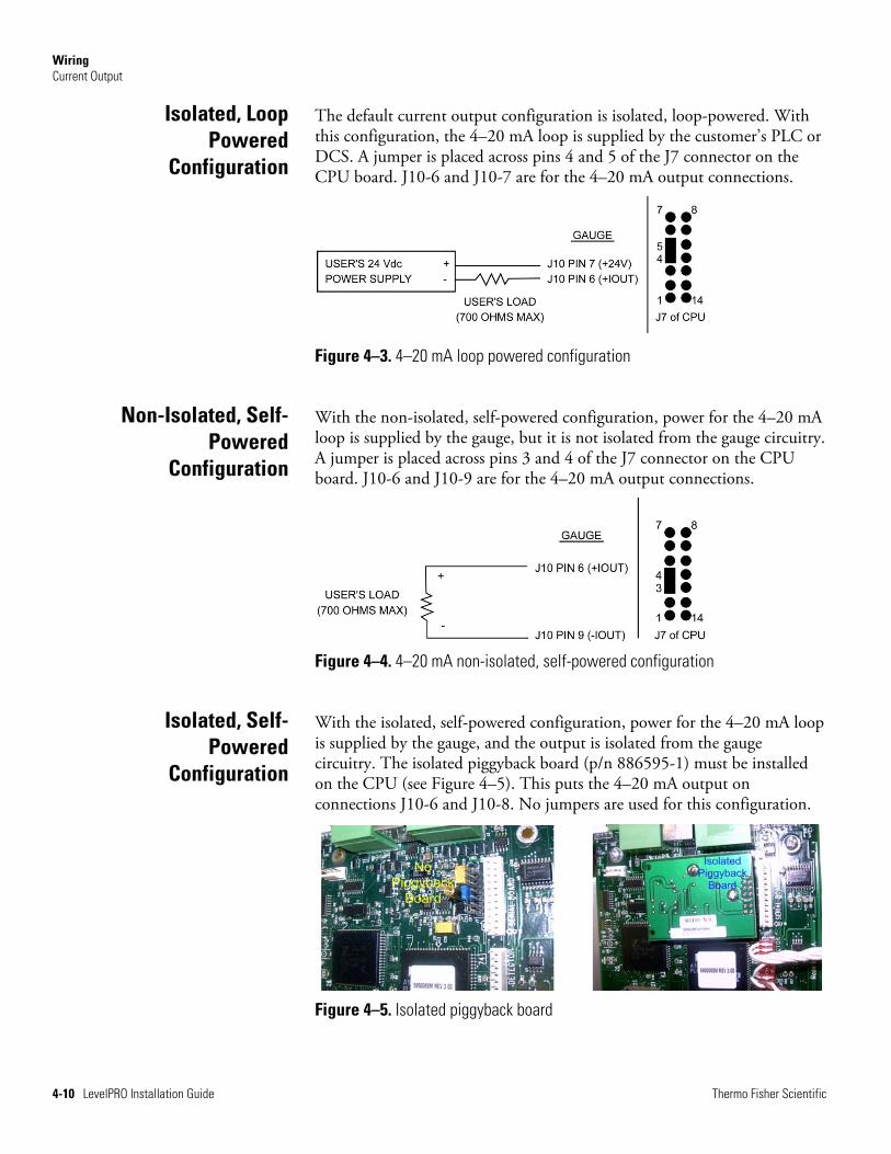
The default current output configuration is isolated, loop-powered. With this configuration, the 4–20 mA loop is supplied by the customer’s PLC or DCS. A jumper is placed across pins 4 and 5 of the J7 connector on the CPU board. J10-6 and J10-7 are for the 4–20 mA output connections.
Figure 4–3. 4–20 mA loop powered configuration
With the non-isolated, self-powered configuration, power for the 4–20 mA loop is supplied by the gauge, but it is not isolated from the gauge circuitry. A jumper is placed across pins 3 and 4 of the J7 connector on the CPU board. J10-6 and J10-9 are for the 4–20 mA output connections.
Figure 4–4. 4–20 mA non-isolated, self-powered configuration
With the isolated, self-powered configuration, power for the 4–20 mA loop is supplied by the gauge, and the output is isolated from the gauge circuitry. The isolated piggyback board (p/n 886595-1) must be installed on the CPU (see Figure 4–5). This puts the 4–20 mA output on connections J10-6 and J10-8. No jumpers are used for this configuration.
Figure 4–5. Isolated piggyback board
Isolated, Loop Powered
Configuration
Non-Isolated, Self-Powered
Configuration
Isolated, Self-Powered
Configuration
Wiring Cascade Mode Wiring
Thermo Fisher Scientific LevelPRO Installation Guide 4-11
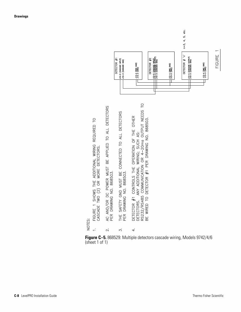
For applications requiring a detector length greater than twelve feet, multiple units can be wired together to act as one continuous detector. In this situation, the highest or top gauge in the line, or cascade, is the master. All wiring for the serial ports, relays, etc. is done in the master unit. Remaining units are slave units. All slaves must be powered in the same manner as the master (either AC or DC).
The lowest gauge in the line must be wired with its CASCADE OUT to the CASCADE IN of the gauge directly above it. Each gauge in the cascade is wired in this manner (CASCADE OUT to the CASCADE IN of the next unit), up to the master gauge. The master has only a CASCADE IN.
Each gauge takes the count rate coming into it on the CASCADE IN line from the detector immediately below it, adds the value to its own internal count rate, and then outputs the total on the CASCADE OUT line to the detector immediately above in the cascade.
Refer to drawings 868503 and 868529 in the drawing appendix for the wiring requirements. Additional information on cascade mode wiring can be found in Technical Bulletin TB-0416-019.
There is an auxiliary connection on connector J10 for applications requiring an outside 4–20 mA signal be input into the LevelPRO and used as a form of compensation adjustment (vapor density, pressure, etc.). The outside 4–20 mA signal should be wired so that the positive connection of the loop is connected at J10 pin 1 and the negative side connected to J10 pin 2. The special equation is then utilized to incorporate this input into the LevelPRO program. Refer to the LevelPRO user guide for information on special equations.
Cascade Mode Wiring
Auxiliary Input Wiring

This page intentionally left blank.
Thermo Fisher Scientific LevelPRO Installation Guide 5-1
Chapter 5 Service & Support
The troubleshooting section in the LevelPRO user guide provides several troubleshooting procedures that may help you resolve the issue you are having. It also provides a list of values that are important to record if you need to contain Thermo Fisher Scientific Technical Support.
You can contact Thermo Fisher Scientific at the locations below.
1410 Gillingham Lane Sugar Land, TX 77478 USA Tel: +1 713-272-0404 Fax: +1 713-272-2272
14 Gormley Industrial Avenue Gormley, Ontario L0H 1G0 CANADA Tel: +1 905-888-8808 Fax: +1 905-888-8828
Ion Path, Road Three Winsford, Cheshire, CW7 3GA UNITED KINGDOM Tel: +44 (0) 1606 548700 Fax: +44 (0) 1606 548711
Unit 702-715, 7/F Tower West Yonghe Plaza No. 28 Andingmen East Street Beijing 100007 CHINA Tel: +86 (10) 8419-3588 Fax: +86 (10) 8419-3580
A-101, 1CC Trade Tower Senapati Bapat Road Pune 411 016 Maharashtra, INDIA Tel: +91 (20) 6626 7000 Fax: +91 (20) 6626 7001
On the Web www.thermoscientific.com
Getting Help

Service & Support Warranty
5-2 LevelPRO Installation Guide Thermo Fisher Scientific
Thermo Scientific products are warranted to be free from defects in material and workmanship at the time of shipment and for one year thereafter. Any claimed defects in Thermo Scientific products must be reported within the warranty period. Thermo Fisher Scientific Inc. (Thermo Fisher) shall have the right to inspect such products at Buyer’s plant or to require Buyer to return such products to Thermo Fisher plant.
In the event Thermo Fisher requests return of its products, Buyer shall ship with transportation charges paid by the Buyer to Thermo Fisher plant. Shipment of repaired or replacement goods from Thermo Fisher plant shall be F.O.B. Thermo Fisher plant. A quotation of proposed work will be sent to the customer. Thermo Fisher shall be liable only to replace or repair, at its option, free of charge, products which are found by Thermo Fisher to be defective in material or workmanship, and which are reported to Thermo Fisher within the warranty period as provided above. This right to replacement shall be Buyer’s exclusive remedy against Thermo Fisher.
Thermo Fisher shall not be liable for labor charges or other losses or damages of any kind or description, including but not limited to, incidental, special or consequential damages caused by defective products. This warranty shall be void if recommendations provided by Thermo Fisher or its Sales Representatives are not followed concerning methods of operation, usage and storage or exposure to harsh conditions.
Materials and / or products furnished to Thermo Fisher by other suppliers shall carry no warranty except such suppliers’ warranties as to materials and workmanship. Thermo Fisher disclaims all warranties, expressed or implied, with respect to such products.
EXCEPT AS OTHERWISE AGREED TO IN WRITING BY Thermo Fisher, THE WARRANTIES GIVEN ABOVE ARE IN LIEU OF ALL OTHER WARRANTIES, EXPRESSED OR IMPLIED, AND Thermo Fisher HEREBY DISCLAIMS ALL OTHER WARRANTIES, INCLUDING THOSE OF MERCHANTABILITY AND FITNESS FOR PURPOSE.
Warranty
Thermo Fisher Scientific LevelPRO Installation Guide A-1
Appendix A Ordering Information
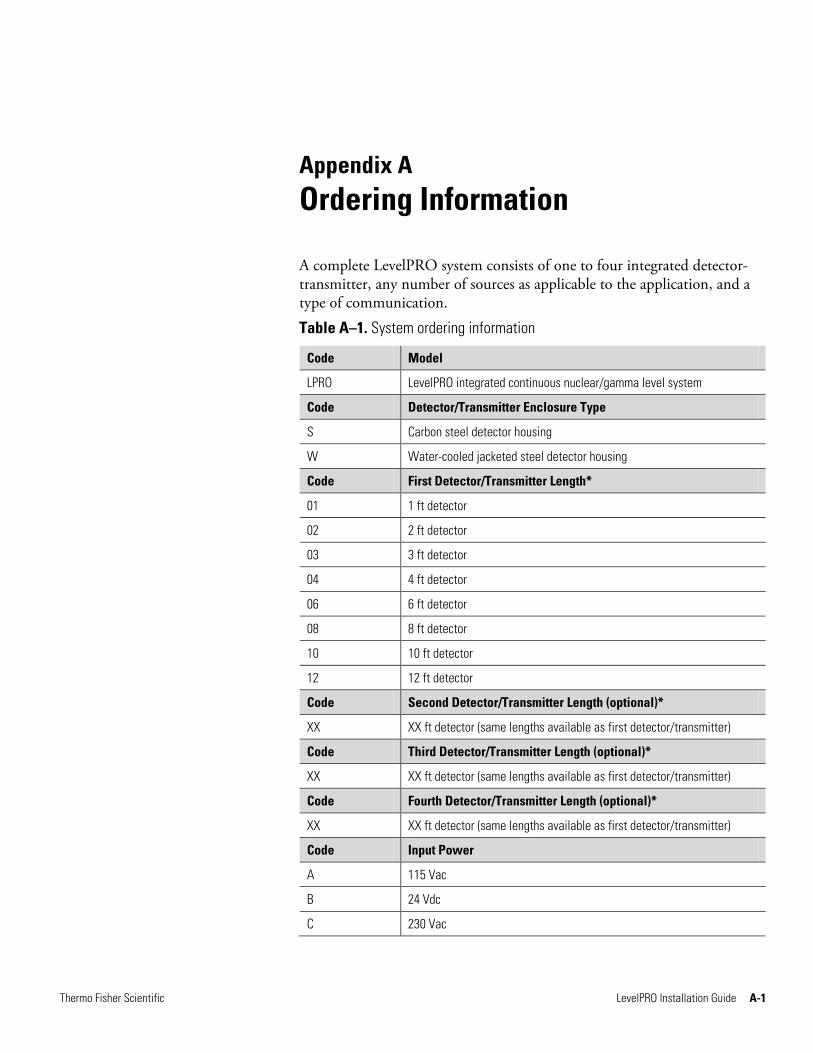
A complete LevelPRO system consists of one to four integrated detector-transmitter, any number of sources as applicable to the application, and a type of communication.
Table A–1. System ordering information
Code Model
LPRO LevelPRO integrated continuous nuclear/gamma level system
Code Detector/Transmitter Enclosure Type
S Carbon steel detector housing
W Water-cooled jacketed steel detector housing
Code First Detector/Transmitter Length*
01 1 ft detector
02 2 ft detector
03 3 ft detector
04 4 ft detector
06 6 ft detector
08 8 ft detector
10 10 ft detector
12 12 ft detector
Code Second Detector/Transmitter Length (optional)*
XX XX ft detector (same lengths available as first detector/transmitter)
Code Third Detector/Transmitter Length (optional)*
XX XX ft detector (same lengths available as first detector/transmitter)
Code Fourth Detector/Transmitter Length (optional)*
XX XX ft detector (same lengths available as first detector/transmitter)
Code Input Power
A 115 Vac
B 24 Vdc
C 230 Vac
Ordering Information
A-2 LevelPRO Installation Guide Thermo Fisher Scientific
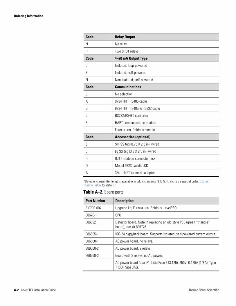
Code Relay Output
N No relay
R Two SPDT relays
Code 4–20 mA Output Type
L Isolated, loop-powered
S Isolated, self-powered
N Non-isolated, self-powered
Code Communications
0 No selection
A 9734 HHT RS485 cable
B 9734 HHT RS485 & RS232 cable
C RS232/RS485 converter
E HART communication module
L FOUNDATION fieldbus module
Code Accessories (optional)
S Sm SS tag (0.75 X 2.5 in), wired
L Lg SS tag (3.3 X 2.5 in), wired
R RJ11 modular connector jack
D Model 9723 backlit LCD
A 3/4-in NPT to metric adapter
*Detector-transmitter lengths available in odd increments (3 ft, 5, ft, etc.) as a special order. Contact Thermo Fisher for details.
Table A–2. Spare parts
Part Number Description
3-0702-007 Upgrade kit, FOUNDATION fieldbus, LevelPRO
88670-1 CPU
886592 Detector board. Note: If replacing an old style PCB (green “triangle” board), use kit 886776.
886595-1 ISO-24 piggyback board. Supports isolated, self-powered current output.
886568-1 AC power board, no relays.
886568-2 AC power board, 2 relays.
868568-3 Board with 2 relays, no AC power.
AC power board fuse, F1 (LittelFuse 313.125), 250V, 0.125A (1/8A), Type T (SB), Size 3AG.
Thermo Fisher Scientific LevelPRO Installation Guide B-1
Appendix B Specifications
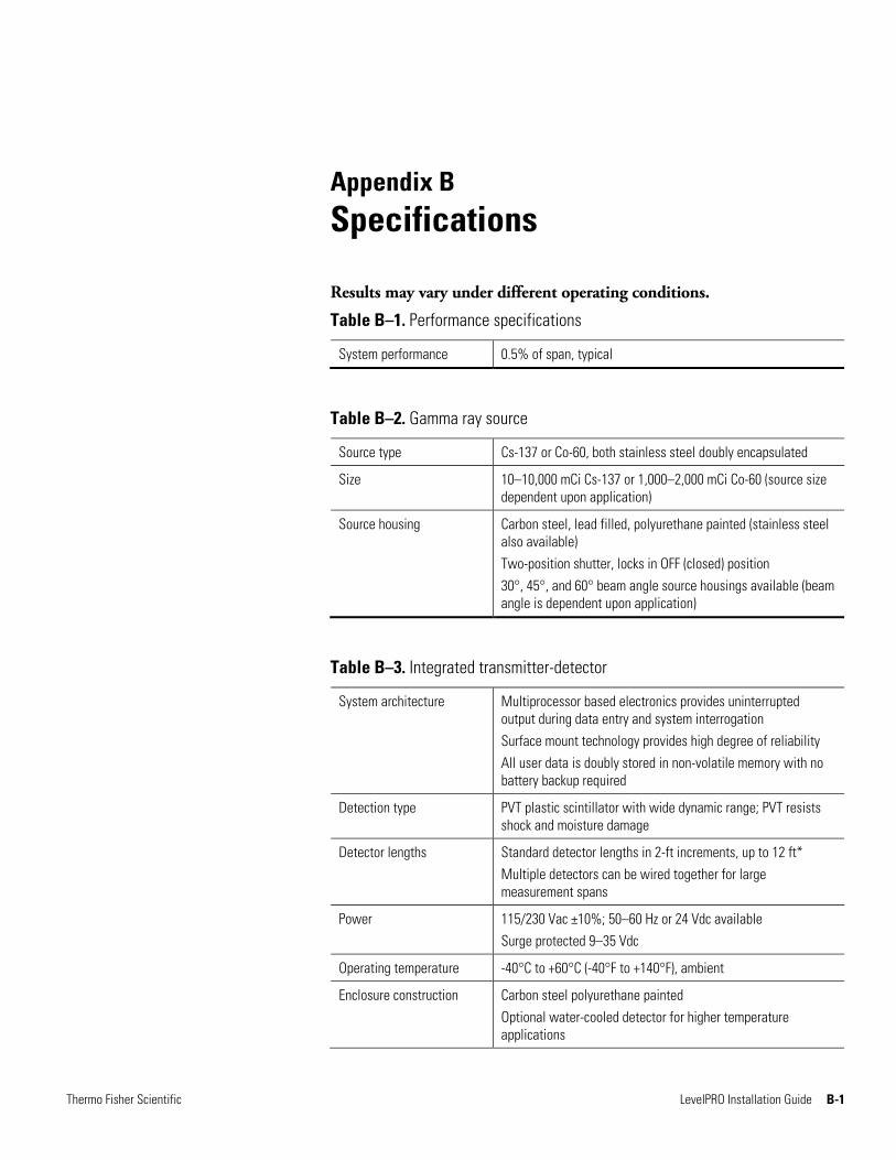
Results may vary under different operating conditions.
Table B–1. Performance specifications
System performance 0.5% of span, typical
Table B–2. Gamma ray source
Source type Cs-137 or Co-60, both stainless steel doubly encapsulated
Size 10–10,000 mCi Cs-137 or 1,000–2,000 mCi Co-60 (source size dependent upon application)
Source housing Carbon steel, lead filled, polyurethane painted (stainless steel also available) Two-position shutter, locks in OFF (closed) position 30°, 45°, and 60° beam angle source housings available (beam angle is dependent upon application)
Table B–3. Integrated transmitter-detector
System architecture Multiprocessor based electronics provides uninterrupted output during data entry and system interrogation Surface mount technology provides high degree of reliability All user data is doubly stored in non-volatile memory with no battery backup required
Detection type PVT plastic scintillator with wide dynamic range; PVT resists shock and moisture damage
Detector lengths Standard detector lengths in 2-ft increments, up to 12 ft* Multiple detectors can be wired together for large measurement spans
Power 115/230 Vac ±10%; 50–60 Hz or 24 Vdc available Surge protected 9–35 Vdc
Operating temperature -40°C to +60°C (-40°F to +140°F), ambient
Enclosure construction Carbon steel polyurethane painted Optional water-cooled detector for higher temperature applications
Specifications
B-2 LevelPRO Installation Guide Thermo Fisher Scientific
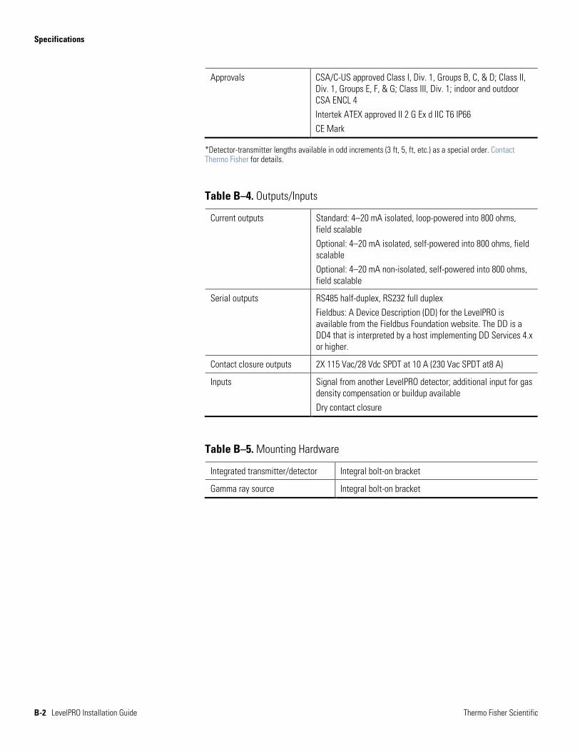
Approvals CSA/C-US approved Class I, Div. 1, Groups B, C, & D; Class II, Div. 1, Groups E, F, & G; Class III, Div. 1; indoor and outdoor CSA ENCL 4 Intertek ATEX approved II 2 G Ex d IIC T6 IP66 CE Mark
*Detector-transmitter lengths available in odd increments (3 ft, 5, ft, etc.) as a special order. Contact Thermo Fisher for details.
Table B–4. Outputs/Inputs
Current outputs Standard: 4–20 mA isolated, loop-powered into 800 ohms, field scalable Optional: 4–20 mA isolated, self-powered into 800 ohms, field scalable Optional: 4–20 mA non-isolated, self-powered into 800 ohms, field scalable
Serial outputs RS485 half-duplex, RS232 full duplex Fieldbus: A Device Description (DD) for the LevelPRO is available from the Fieldbus Foundation website. The DD is a DD4 that is interpreted by a host implementing DD Services 4.x or higher.
Contact closure outputs 2X 115 Vac/28 Vdc SPDT at 10 A (230 Vac SPDT at8 A)
Inputs Signal from another LevelPRO detector; additional input for gas density compensation or buildup available Dry contact closure
Table B–5. Mounting Hardware
Integrated transmitter/detector Integral bolt-on bracket
Gamma ray source Integral bolt-on bracket
Specifications
Thermo Fisher Scientific LevelPRO Installation Guide B-3
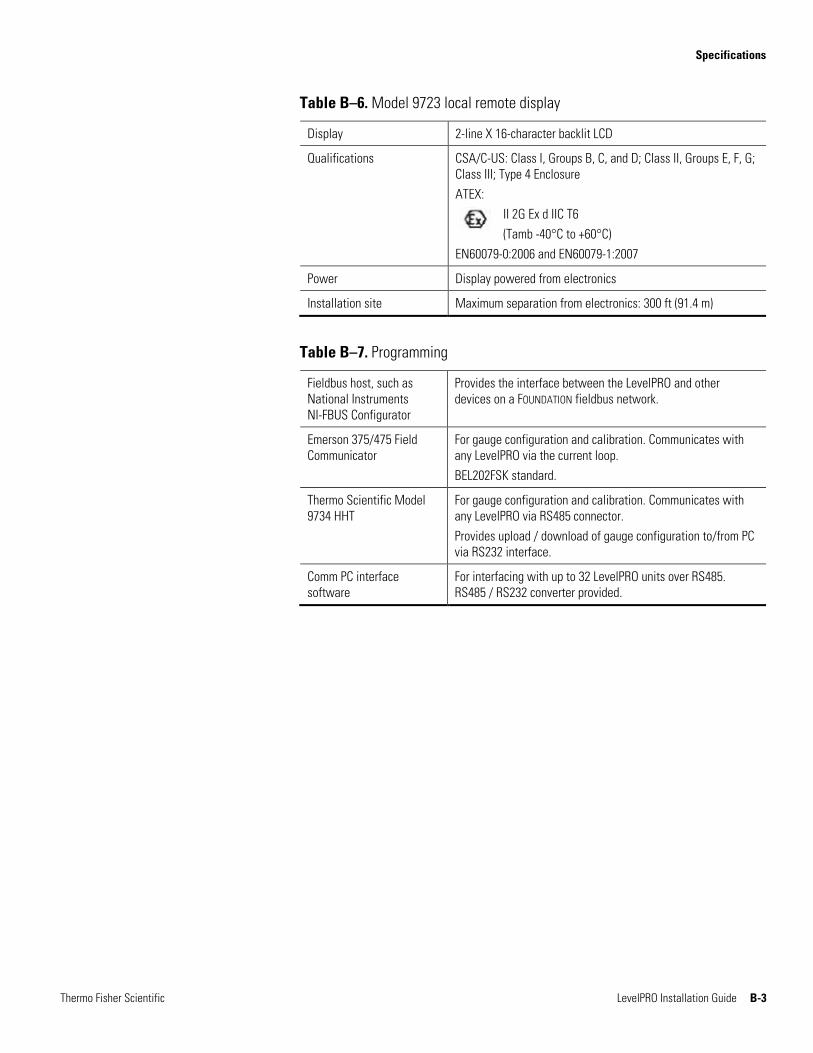
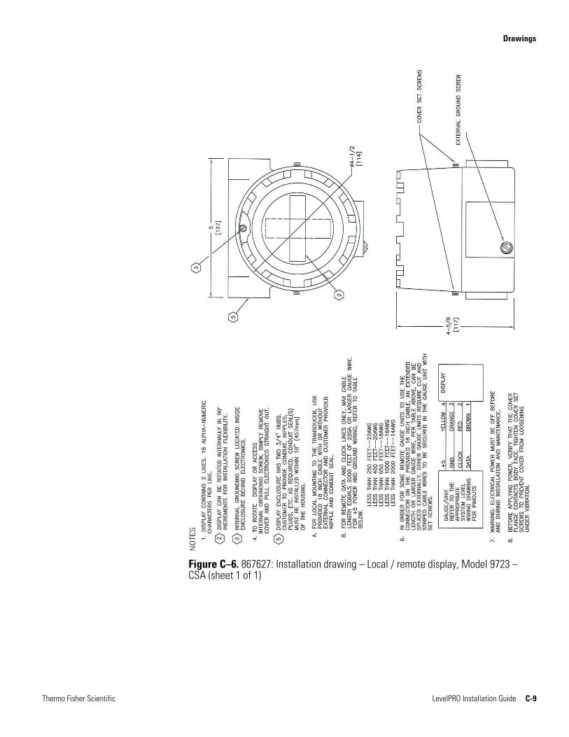
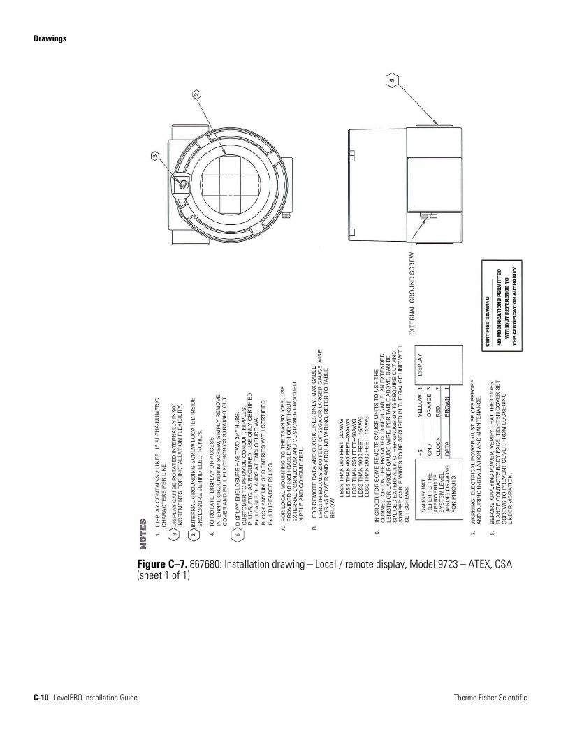
Table B–6. Model 9723 local remote display
Display 2-line X 16-character backlit LCD
Qualifications CSA/C-US: Class I, Groups B, C, and D; Class II, Groups E, F, G; Class III; Type 4 Enclosure ATEX:
II 2G Ex d IIC T6 (Tamb -40°C to +60°C)
EN60079-0:2006 and EN60079-1:2007
Power Display powered from electronics
Installation site Maximum separation from electronics: 300 ft (91.4 m)
Table B–7. Programming
Fieldbus host, such as National Instruments NI-FBUS Configurator
Provides the interface between the LevelPRO and other devices on a FOUNDATION fieldbus network.
Emerson 375/475 Field Communicator
For gauge configuration and calibration. Communicates with any LevelPRO via the current loop. BEL202FSK standard.
Thermo Scientific Model 9734 HHT
For gauge configuration and calibration. Communicates with any LevelPRO via RS485 connector. Provides upload / download of gauge configuration to/from PC via RS232 interface.
Comm PC interface software
For interfacing with up to 32 LevelPRO units over RS485. RS485 / RS232 converter provided.

This page intentionally left blank.
Thermo Fisher Scientific LevelPRO Installation Guide C-1
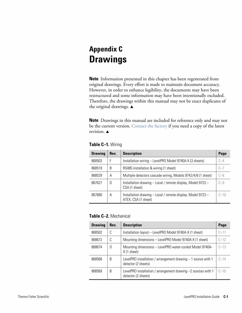
Appendix C Drawings
Note Information presented in this chapter has been regenerated from original drawings. Every effort is made to maintain document accuracy. However, in order to enhance legibility, the documents may have been restructured and some information may have been intentionally excluded. Therefore, the drawings within this manual may not be exact duplicates of the original drawings.
Note Drawings in this manual are included for reference only and may not be the current version. Contact the factory if you need a copy of the latest revision.
Table C–1. Wiring
Drawing Rev. Description Page
868503 F Installation wiring – LevelPRO Model 9740A-X (3 sheets) C–4
868519 B RS485 installation & wiring (1 sheet) C–7
868529 A Multiple detectors cascade wiring, Models 9742/4/6 (1 sheet) C–8
867627 D Installation drawing – Local / remote display, Model 9723 – CSA (1 sheet)
C–9
867680 A Installation drawing – Local / remote display, Model 9723 – ATEX, CSA (1 sheet)
C–10
Table C–2. Mechanical
Drawing Rev. Description Page
868502 C Installation layout – LevelPRO Model 9740A-X (1 sheet) C–11
868672 C Mounting dimensions – LevelPRO Model 9740A-X (1 sheet) C–12
868674 D Mounting dimensions – LevelPRO water-cooled Model 9740A-X (1 sheet)
C–13
868568 B LevelPRO installation / arrangement drawing – 1 source with 1 detector (2 sheets)
C–14
868569 B LevelPRO installation / arrangement drawing –2 sources with 1 detector (2 sheets)
C–16
Drawings
C-2 LevelPRO Installation Guide Thermo Fisher Scientific
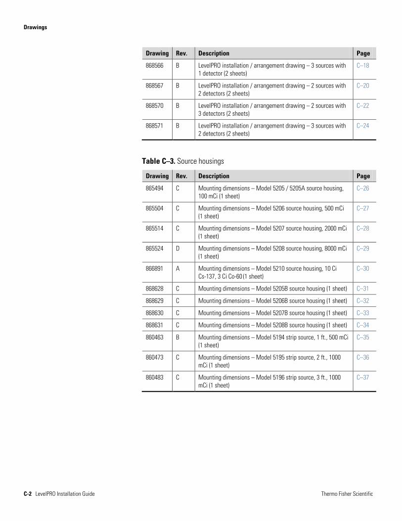
Drawing Rev. Description Page
868566 B LevelPRO installation / arrangement drawing – 3 sources with 1 detector (2 sheets)
C–18
868567 B LevelPRO installation / arrangement drawing – 2 sources with 2 detectors (2 sheets)
C–20
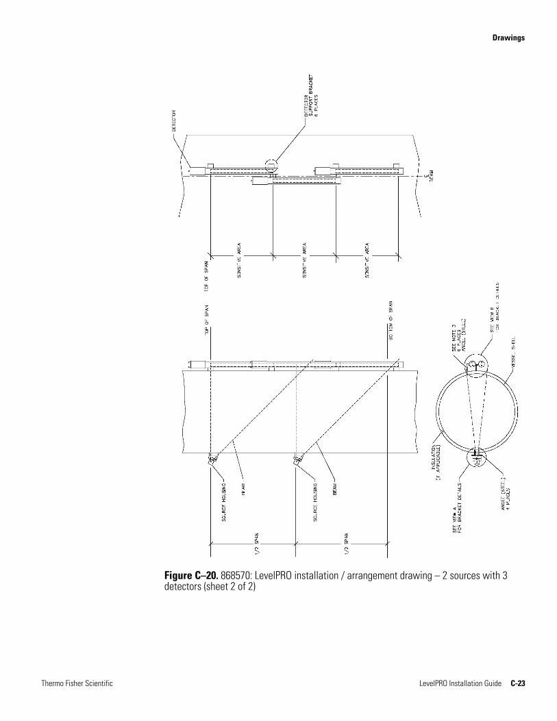
868570 B LevelPRO installation / arrangement drawing – 2 sources with 3 detectors (2 sheets)
C–22
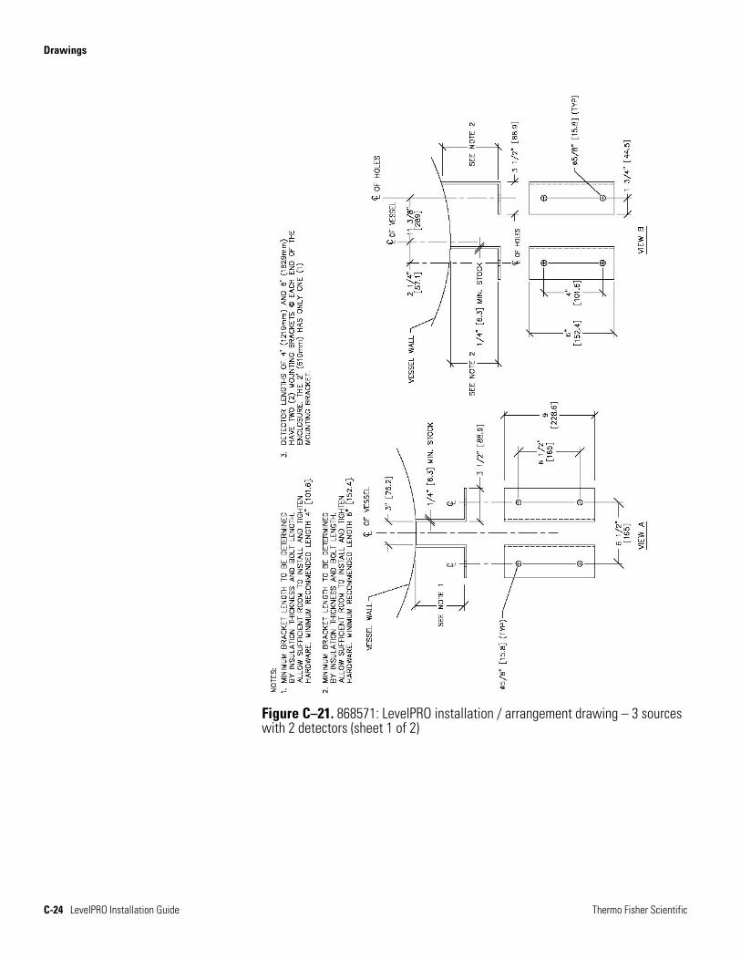
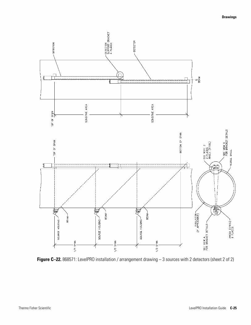
868571 B LevelPRO installation / arrangement drawing – 3 sources with 2 detectors (2 sheets)
C–24
Table C–3. Source housings
Drawing Rev. Description Page
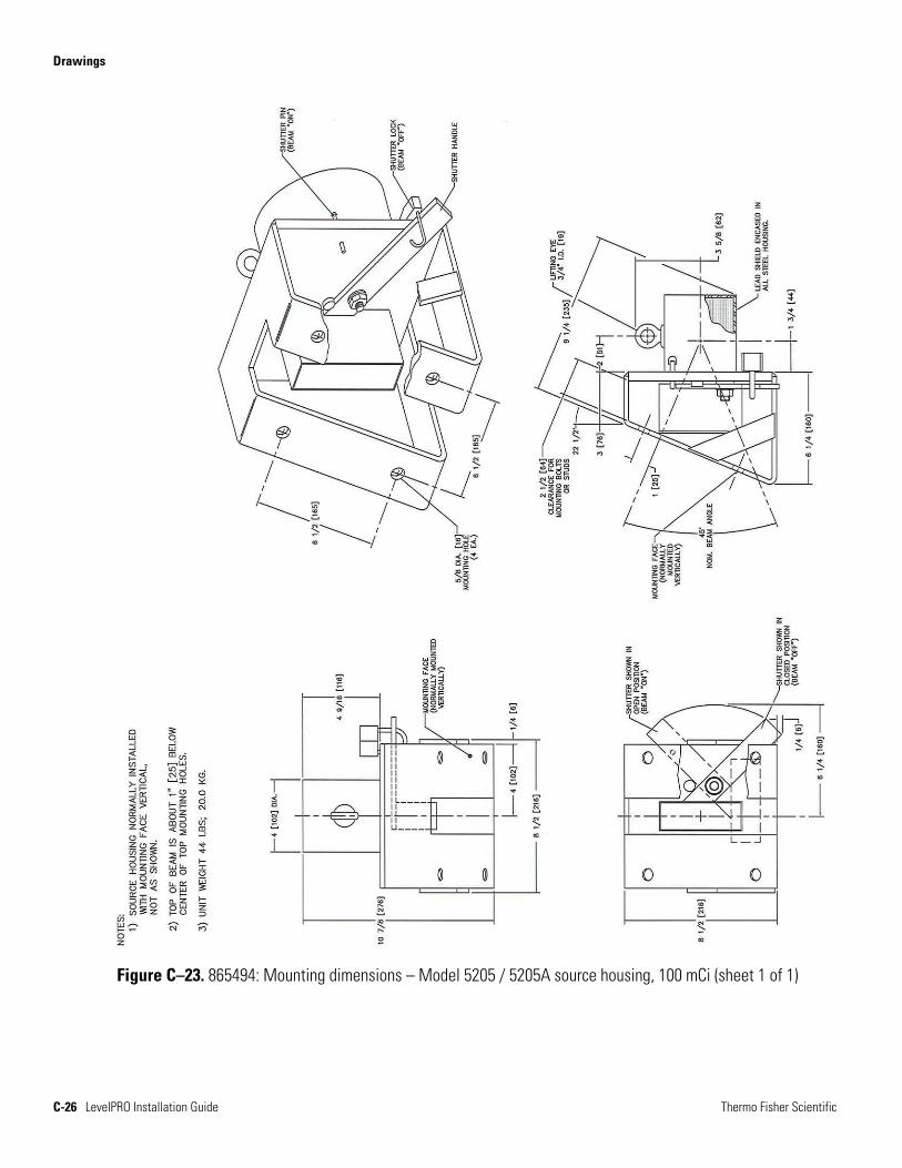
865494 C Mounting dimensions – Model 5205 / 5205A source housing, 100 mCi (1 sheet)
C–26
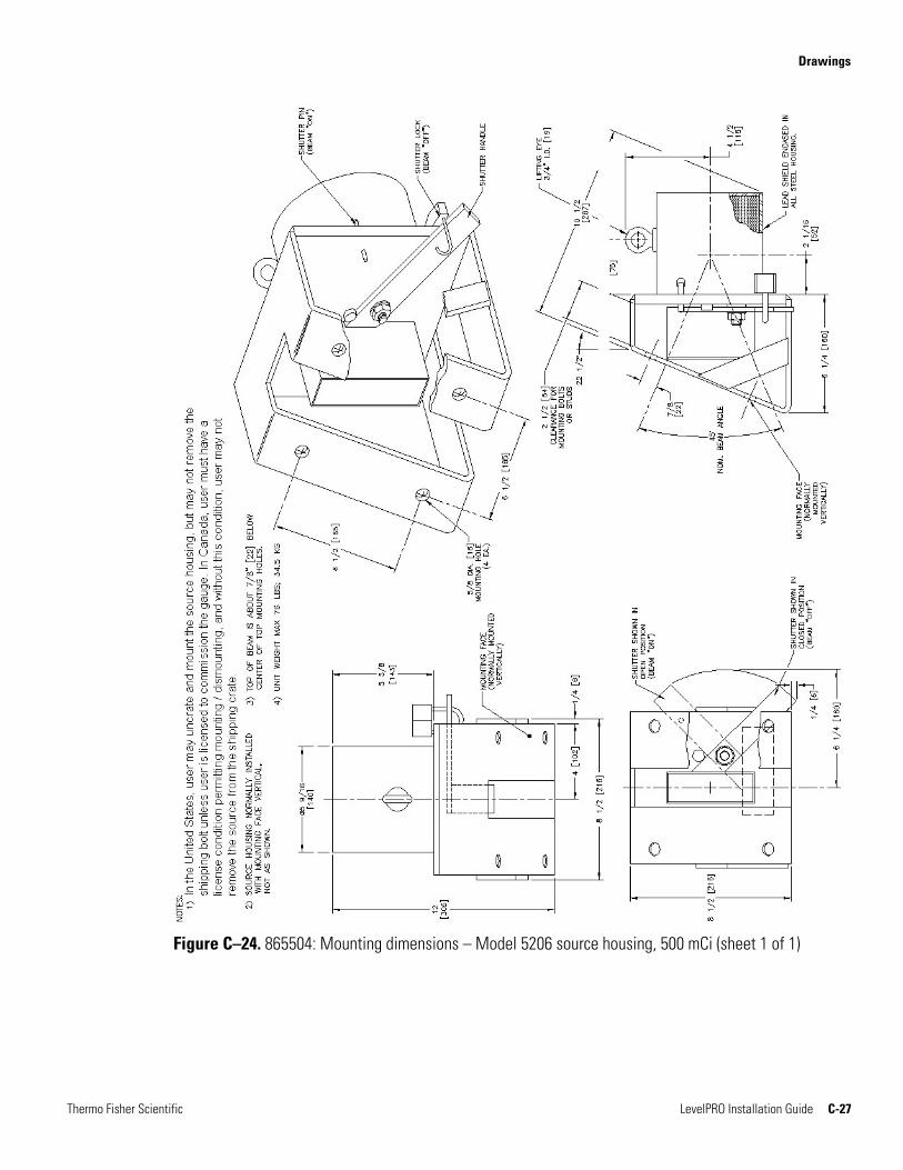
865504 C Mounting dimensions – Model 5206 source housing, 500 mCi (1 sheet)
C–27
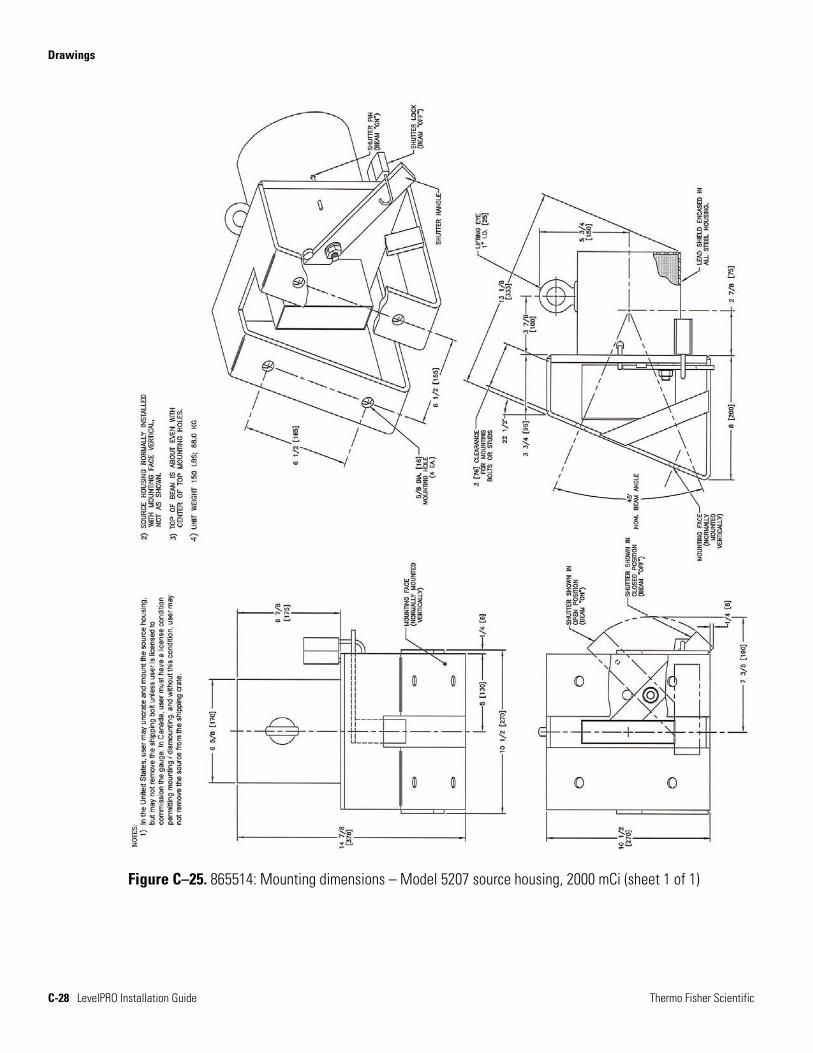
865514 C Mounting dimensions – Model 5207 source housing, 2000 mCi (1 sheet)
C–28
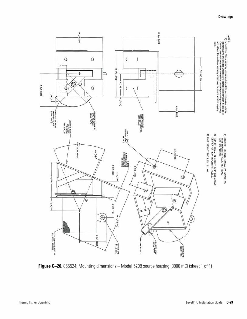
865524 D Mounting dimensions – Model 5208 source housing, 8000 mCi (1 sheet)
C–29
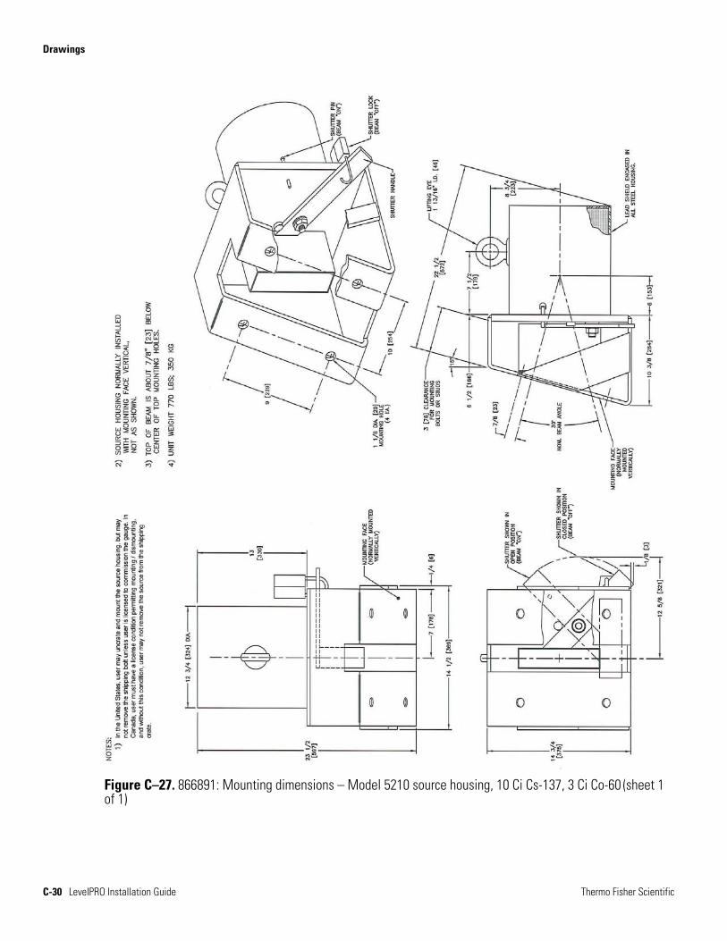
866891 A Mounting dimensions – Model 5210 source housing, 10 Ci Cs-137, 3 Ci Co-60 (1 sheet)
C–30
868628 C Mounting dimensions – Model 5205B source housing (1 sheet) C–31
868629 C Mounting dimensions – Model 5206B source housing (1 sheet) C–32
868630 C Mounting dimensions – Model 5207B source housing (1 sheet) C–33
868631 C Mounting dimensions – Model 5208B source housing (1 sheet) C–34
860463 B Mounting dimensions – Model 5194 strip source, 1 ft., 500 mCi (1 sheet)
C–35
860473 C Mounting dimensions – Model 5195 strip source, 2 ft., 1000 mCi (1 sheet)
C–36
860483 C Mounting dimensions – Model 5196 strip source, 3 ft., 1000 mCi (1 sheet)
C–37
Drawings
Thermo Fisher Scientific LevelPRO Installation Guide C-3
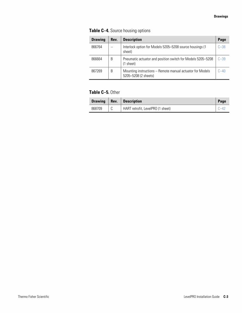
Table C–4. Source housing options
Drawing Rev. Description Page
866764 -- Interlock option for Models 5205–5208 source housings (1 sheet)
C–38
866664 B Pneumatic actuator and position switch for Models 5205–5208 (1 sheet)
C–39
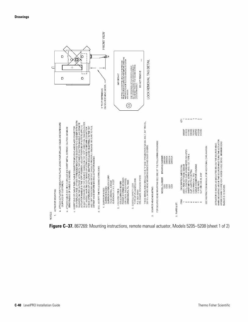
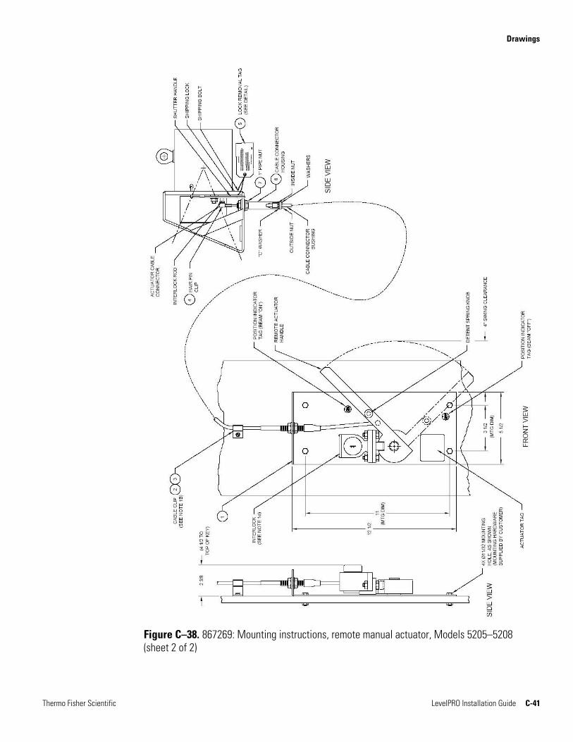
867269 B Mounting instructions – Remote manual actuator for Models 5205–5208 (2 sheets)
C–40
Table C–5. Other
Drawing Rev. Description Page
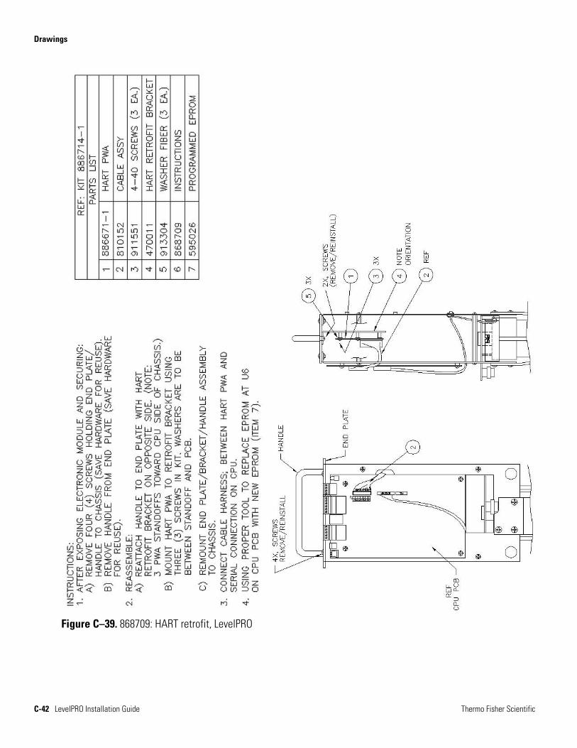
868709 C HART retrofit, LevelPRO (1 sheet) C–42
Drawings
C-4 LevelPRO Installation Guide Thermo Fisher Scientific
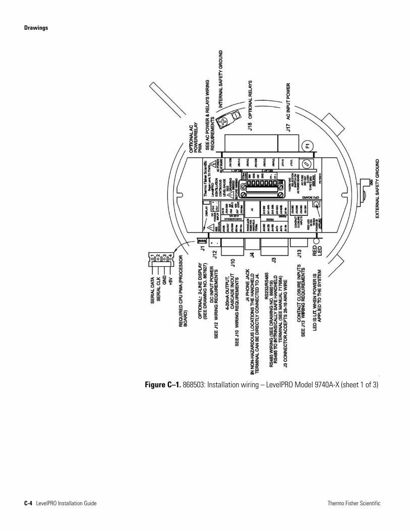
Figure C–1. 868503: Installation wiring – LevelPRO Model 9740A-X (sheet 1 of 3)
Drawings
Thermo Fisher Scientific LevelPRO Installation Guide C-5
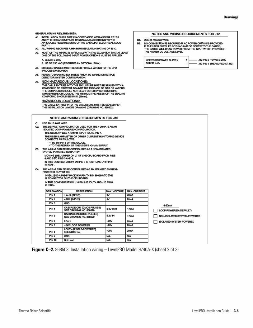
Figure C–2. 868503: Installation wiring – LevelPRO Model 9740A-X (sheet 2 of 3)
Drawings
C-6 LevelPRO Installation Guide Thermo Fisher Scientific
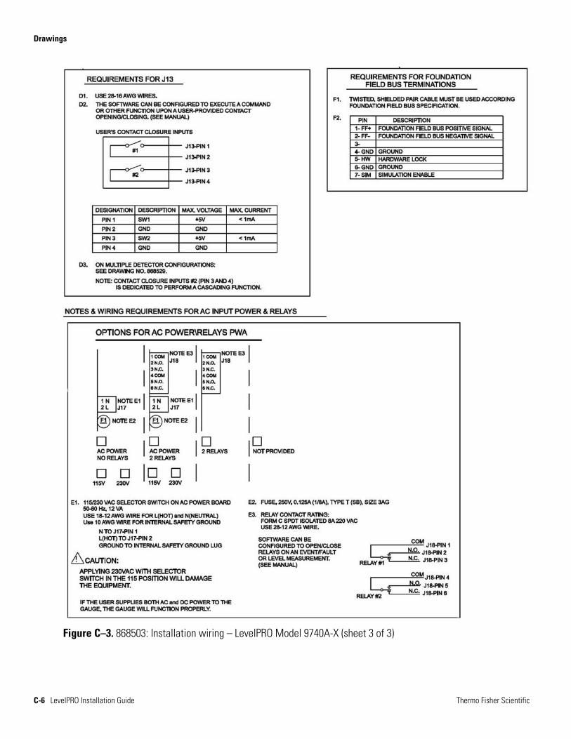
Figure C–3. 868503: Installation wiring – LevelPRO Model 9740A-X (sheet 3 of 3)
Drawings
Thermo Fisher Scientific LevelPRO Installation Guide C-7
Figure C–4. 868519: RS485 installation & wiring (sheet 1 of 1)
Drawings
C-8 LevelPRO Installation Guide Thermo Fisher Scientific
Figure C–5. 868529: Multiple detectors cascade wiring, Models 9742/4/6 (sheet 1 of 1)
Drawings
Thermo Fisher Scientific LevelPRO Installation Guide C-9
Figure C–6. 867627: Installation drawing – Local / remote display, Model 9723 – CSA (sheet 1 of 1)
Drawings
C-10 LevelPRO Installation Guide Thermo Fisher Scientific
Figure C–7. 867680: Installation drawing – Local / remote display, Model 9723 – ATEX, CSA (sheet 1 of 1)
Drawings
Thermo Fisher Scientific LevelPRO Installation Guide C-11
Figure C–8. 868502: Installation layout – LevelPRO Model 9740A-X (sheet 1 of 1)
Drawings
C-12 LevelPRO Installation Guide Thermo Fisher Scientific
Figure C–9. 868672: Mounting dimensions – LevelPRO Model 9740A-X (sheet 1 of 1)
Drawings
Thermo Fisher Scientific LevelPRO Installation Guide C-13
Figure C–10. 868674: Mounting dimensions – LevelPRO water-cooled Model 9740A-X (sheet 1 of 1)
Drawings
C-14 LevelPRO Installation Guide Thermo Fisher Scientific
Figure C–11. 868568: LevelPRO installation / arrangement drawing – 1 source with 1 detector (sheet 1 of 2)
Drawings
Thermo Fisher Scientific LevelPRO Installation Guide C-15
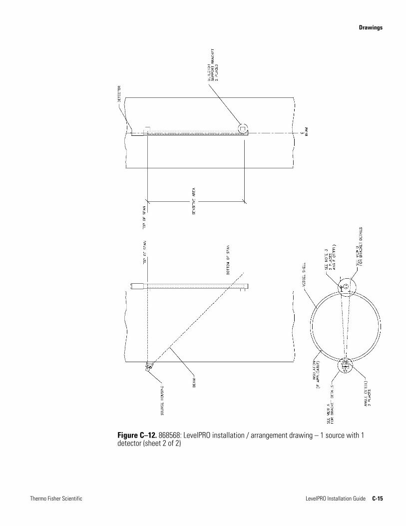
Figure C–12. 868568: LevelPRO installation / arrangement drawing – 1 source with 1 detector (sheet 2 of 2)
Drawings
C-16 LevelPRO Installation Guide Thermo Fisher Scientific
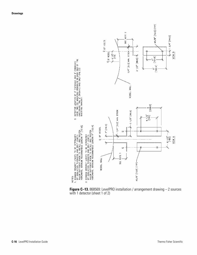
Figure C–13. 868569: LevelPRO installation / arrangement drawing – 2 sources with 1 detector (sheet 1 of 2)
Drawings
Thermo Fisher Scientific LevelPRO Installation Guide C-17
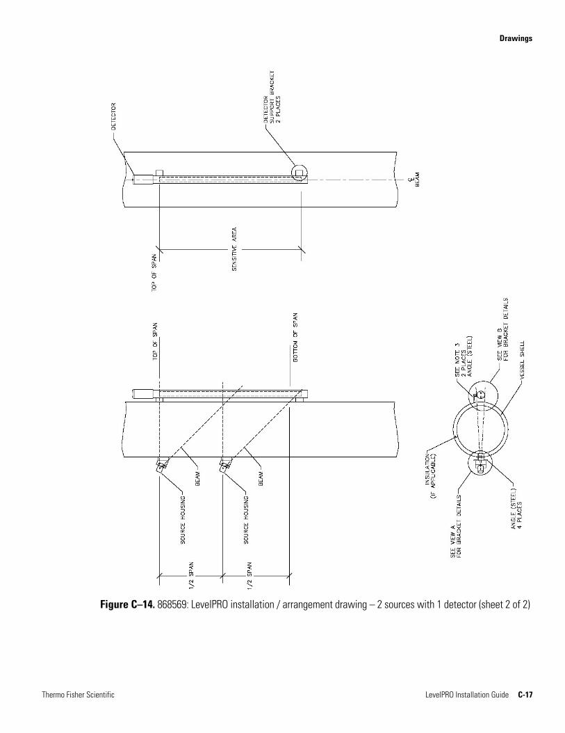
Figure C–14. 868569: LevelPRO installation / arrangement drawing – 2 sources with 1 detector (sheet 2 of 2)
Drawings
C-18 LevelPRO Installation Guide Thermo Fisher Scientific
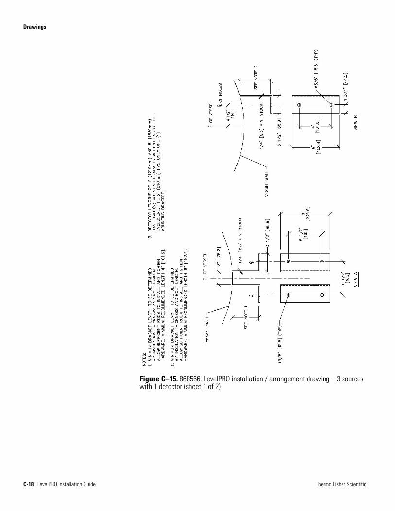
Figure C–15. 868566: LevelPRO installation / arrangement drawing – 3 sources with 1 detector (sheet 1 of 2)
Drawings
Thermo Fisher Scientific LevelPRO Installation Guide C-19
Figure C–16. 868566: LevelPRO installation / arrangement drawing – 3 sources with 1 detector (sheet 2 of 2)
Drawings
C-20 LevelPRO Installation Guide Thermo Fisher Scientific
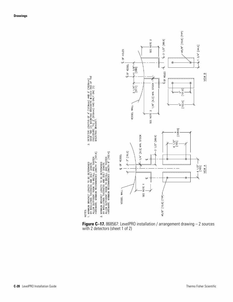
Figure C–17. 868567: LevelPRO installation / arrangement drawing – 2 sources with 2 detectors (sheet 1 of 2)
Drawings
Thermo Fisher Scientific LevelPRO Installation Guide C-21
Figure C–18. 868567: LevelPRO installation / arrangement drawing – 2 sources with 2 detectors (sheet 2 of 2)
Drawings
C-22 LevelPRO Installation Guide Thermo Fisher Scientific
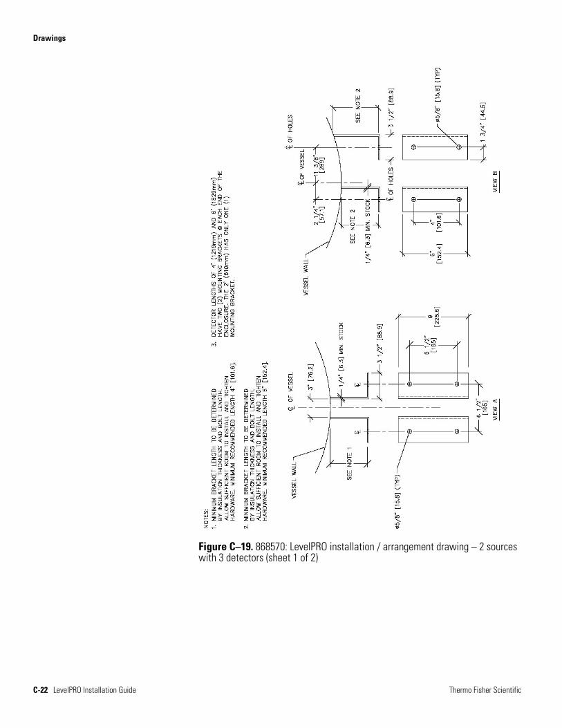
Figure C–19. 868570: LevelPRO installation / arrangement drawing – 2 sources with 3 detectors (sheet 1 of 2)
Drawings
Thermo Fisher Scientific LevelPRO Installation Guide C-23
Figure C–20. 868570: LevelPRO installation / arrangement drawing – 2 sources with 3 detectors (sheet 2 of 2)
Drawings
C-24 LevelPRO Installation Guide Thermo Fisher Scientific
Figure C–21. 868571: LevelPRO installation / arrangement drawing – 3 sources with 2 detectors (sheet 1 of 2)
Drawings
Thermo Fisher Scientific LevelPRO Installation Guide C-25
Figure C–22. 868571: LevelPRO installation / arrangement drawing – 3 sources with 2 detectors (sheet 2 of 2)
Drawings
C-26 LevelPRO Installation Guide Thermo Fisher Scientific
Figure C–23. 865494: Mounting dimensions – Model 5205 / 5205A source housing, 100 mCi (sheet 1 of 1)
Drawings
Thermo Fisher Scientific LevelPRO Installation Guide C-27
Figure C–24. 865504: Mounting dimensions – Model 5206 source housing, 500 mCi (sheet 1 of 1)
Drawings
C-28 LevelPRO Installation Guide Thermo Fisher Scientific
Figure C–25. 865514: Mounting dimensions – Model 5207 source housing, 2000 mCi (sheet 1 of 1)
Drawings
Thermo Fisher Scientific LevelPRO Installation Guide C-29
Figure C–26. 865524: Mounting dimensions – Model 5208 source housing, 8000 mCi (sheet 1 of 1)
Drawings
C-30 LevelPRO Installation Guide Thermo Fisher Scientific
Figure C–27. 866891: Mounting dimensions – Model 5210 source housing, 10 Ci Cs-137, 3 Ci Co-60 (sheet 1 of 1)
Drawings
Thermo Fisher Scientific LevelPRO Installation Guide C-31
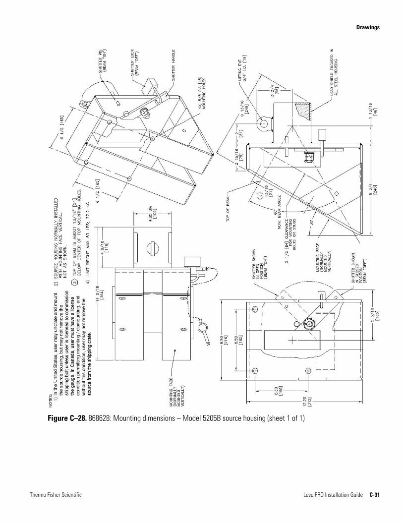
Figure C–28. 868628: Mounting dimensions – Model 5205B source housing (sheet 1 of 1)
Drawings
C-32 LevelPRO Installation Guide Thermo Fisher Scientific
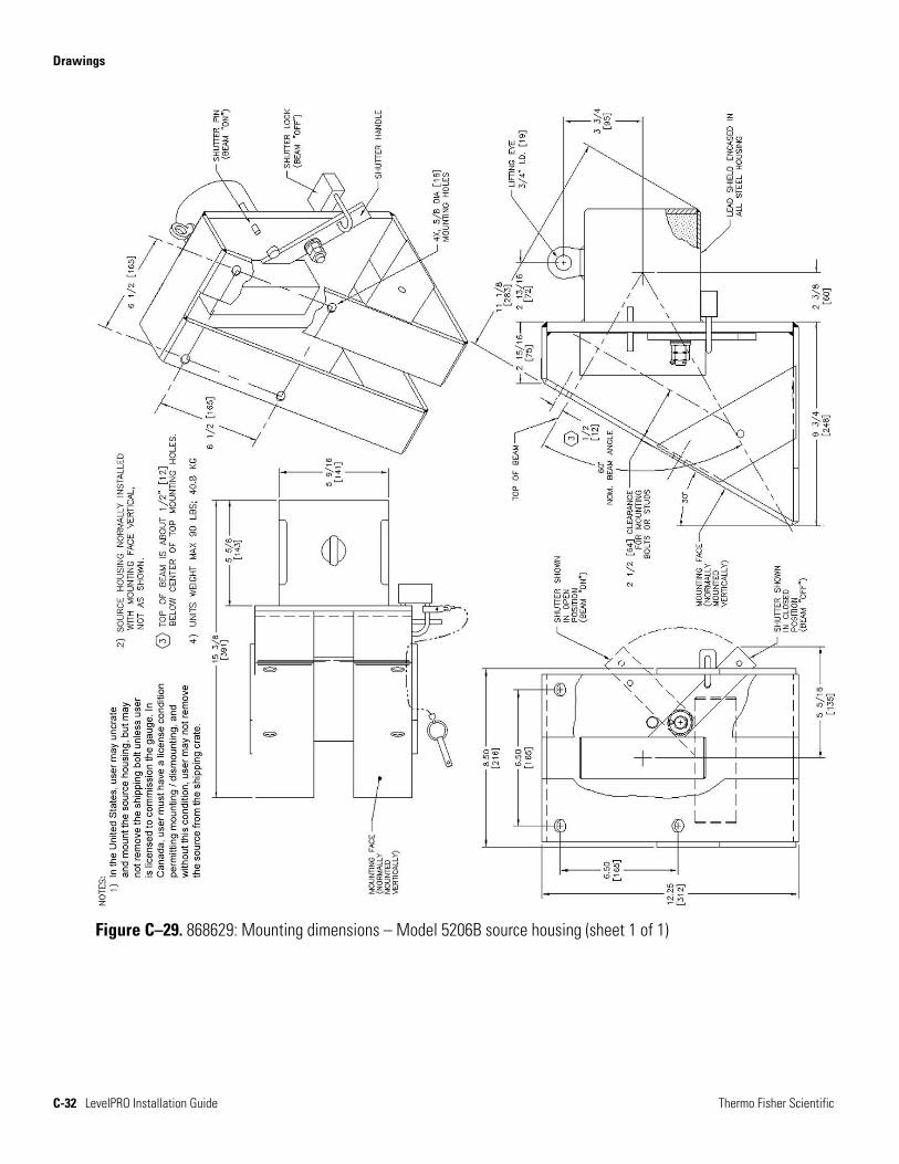
Figure C–29. 868629: Mounting dimensions – Model 5206B source housing (sheet 1 of 1)
Drawings
Thermo Fisher Scientific LevelPRO Installation Guide C-33
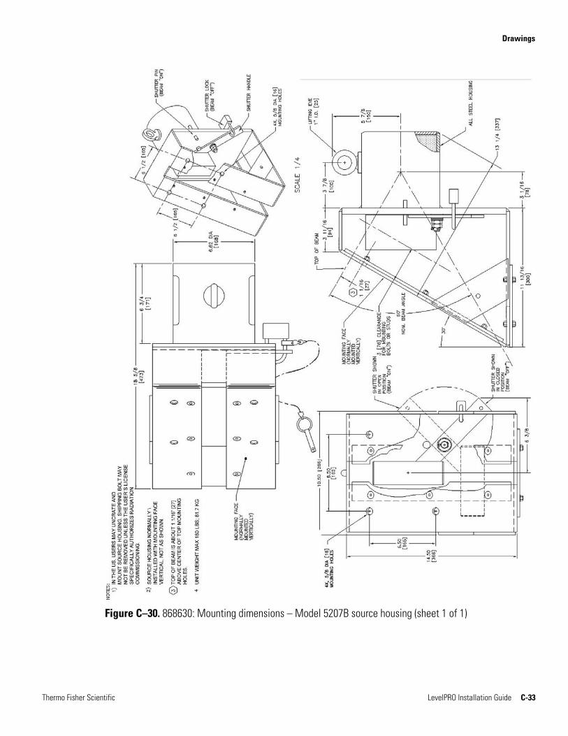
Figure C–30. 868630: Mounting dimensions – Model 5207B source housing (sheet 1 of 1)
Drawings
C-34 LevelPRO Installation Guide Thermo Fisher Scientific
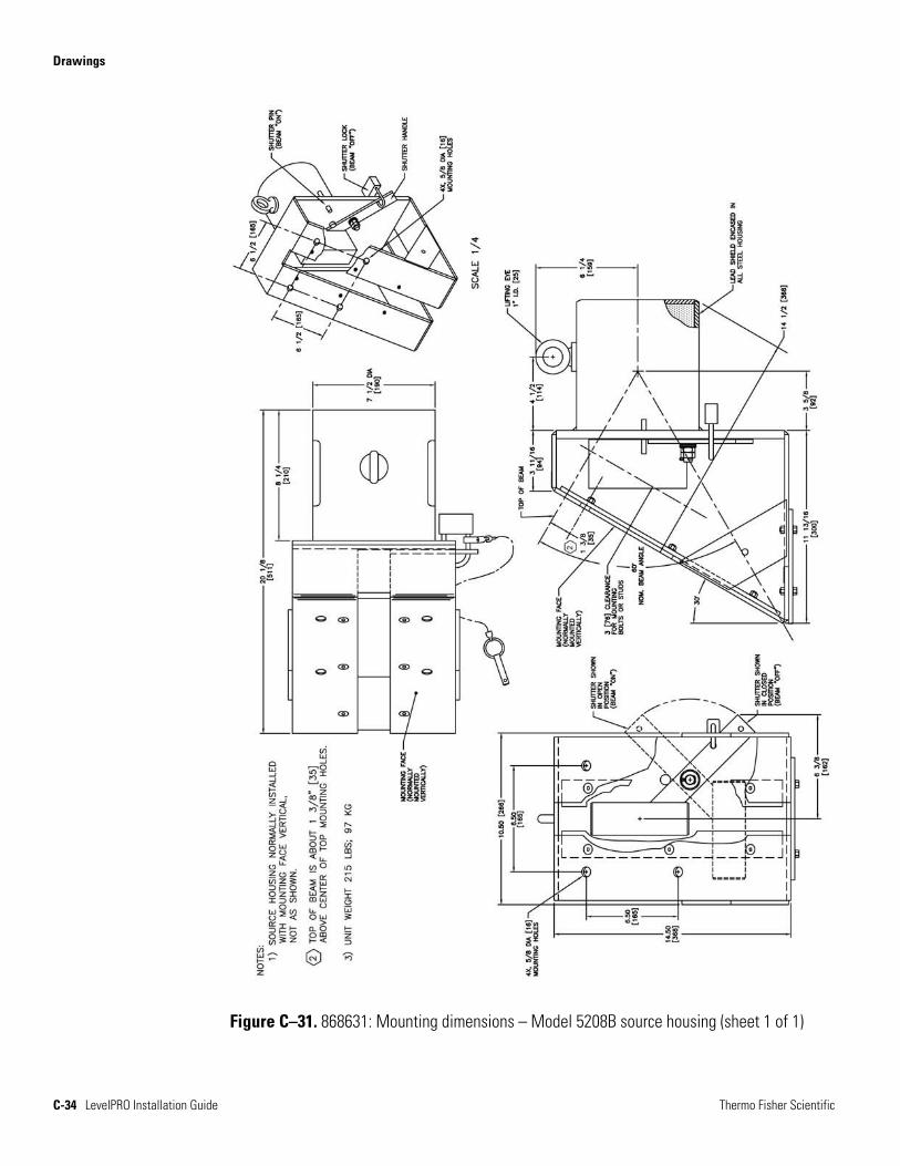
Figure C–31. 868631: Mounting dimensions – Model 5208B source housing (sheet 1 of 1)
Drawings
Thermo Fisher Scientific LevelPRO Installation Guide C-35
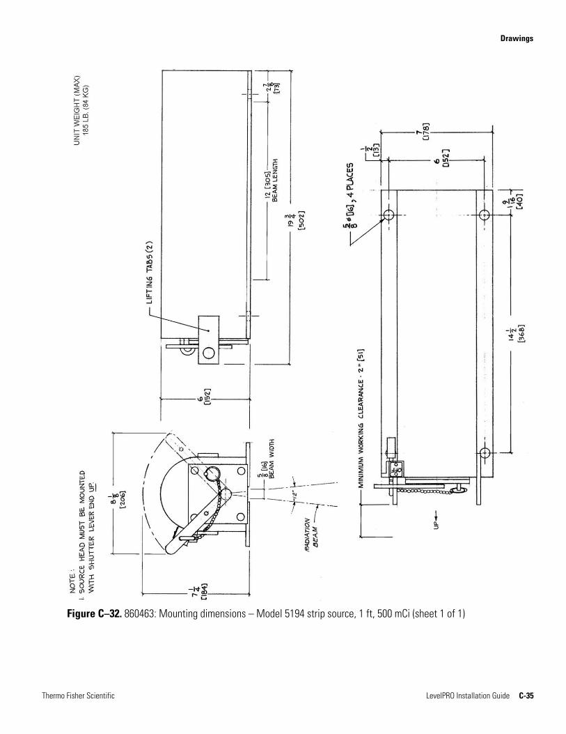
Figure C–32. 860463: Mounting dimensions – Model 5194 strip source, 1 ft, 500 mCi (sheet 1 of 1)
Drawings
C-36 LevelPRO Installation Guide Thermo Fisher Scientific
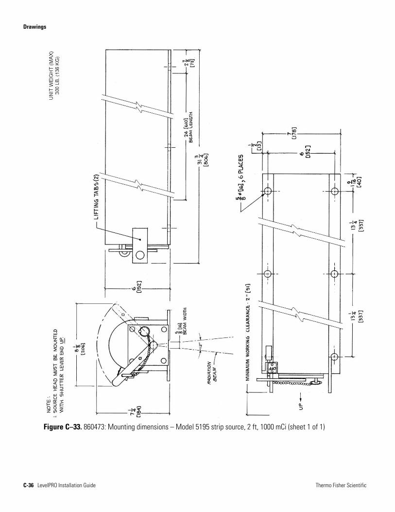
Figure C–33. 860473: Mounting dimensions – Model 5195 strip source, 2 ft, 1000 mCi (sheet 1 of 1)
Drawings
Thermo Fisher Scientific LevelPRO Installation Guide C-37
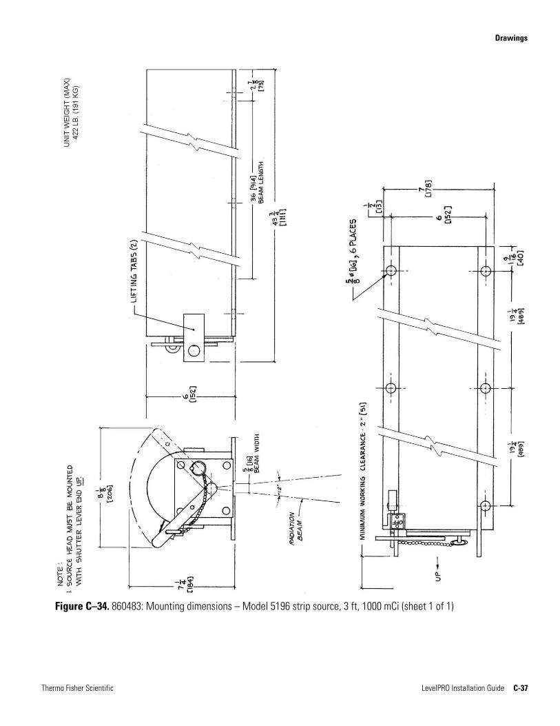
Figure C–34. 860483: Mounting dimensions – Model 5196 strip source, 3 ft, 1000 mCi (sheet 1 of 1)
Drawings
C-38 LevelPRO Installation Guide Thermo Fisher Scientific
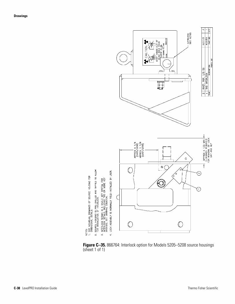
Figure C–35. 866764: Interlock option for Models 5205–5208 source housings (sheet 1 of 1)
Drawings
Thermo Fisher Scientific LevelPRO Installation Guide C-39
Figure C–36. 866664: Models 5205–5208 pneumatic actuator and position switch (sheet 1 of 1)
Drawings
C-40 LevelPRO Installation Guide Thermo Fisher Scientific
Figure C–37. 867269: Mounting instructions, remote manual actuator, Models 5205–5208 (sheet 1 of 2)
Drawings
Thermo Fisher Scientific LevelPRO Installation Guide C-41
Figure C–38. 867269: Mounting instructions, remote manual actuator, Models 5205–5208 (sheet 2 of 2)
Drawings
C-42 LevelPRO Installation Guide Thermo Fisher Scientific
Figure C–39. 868709: HART retrofit, LevelPRO
Thermo Fisher Scientific LevelPRO Installation Guide D-1
Appendix D Replacing the CPU PROM & HART PROM
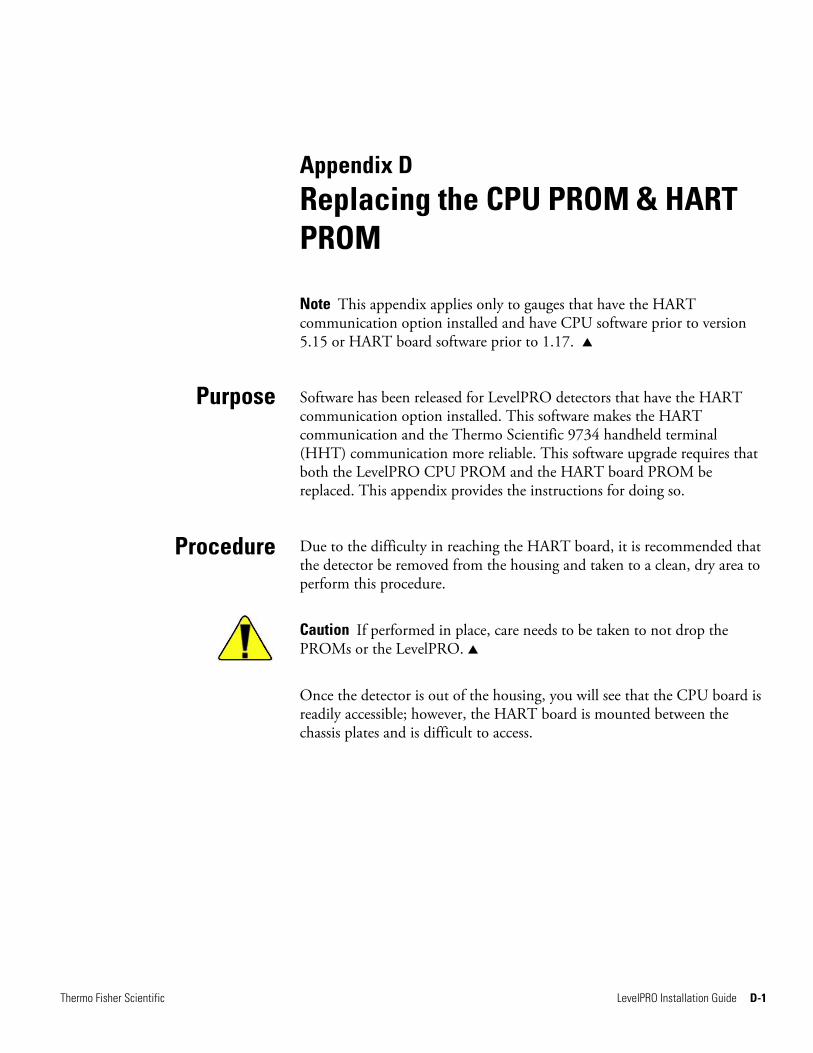
Note This appendix applies only to gauges that have the HART communication option installed and have CPU software prior to version 5.15 or HART board software prior to 1.17.
Software has been released for LevelPRO detectors that have the HART communication option installed. This software makes the HART communication and the Thermo Scientific 9734 handheld terminal (HHT) communication more reliable. This software upgrade requires that both the LevelPRO CPU PROM and the HART board PROM be replaced. This appendix provides the instructions for doing so.
Due to the difficulty in reaching the HART board, it is recommended that the detector be removed from the housing and taken to a clean, dry area to perform this procedure.
Caution If performed in place, care needs to be taken to not drop the PROMs or the LevelPRO.
Once the detector is out of the housing, you will see that the CPU board is readily accessible; however, the HART board is mounted between the chassis plates and is difficult to access.
Purpose
Procedure
Replacing the CPU PROM & HART PROM Procedure
D-2 LevelPRO Installation Guide Thermo Fisher Scientific
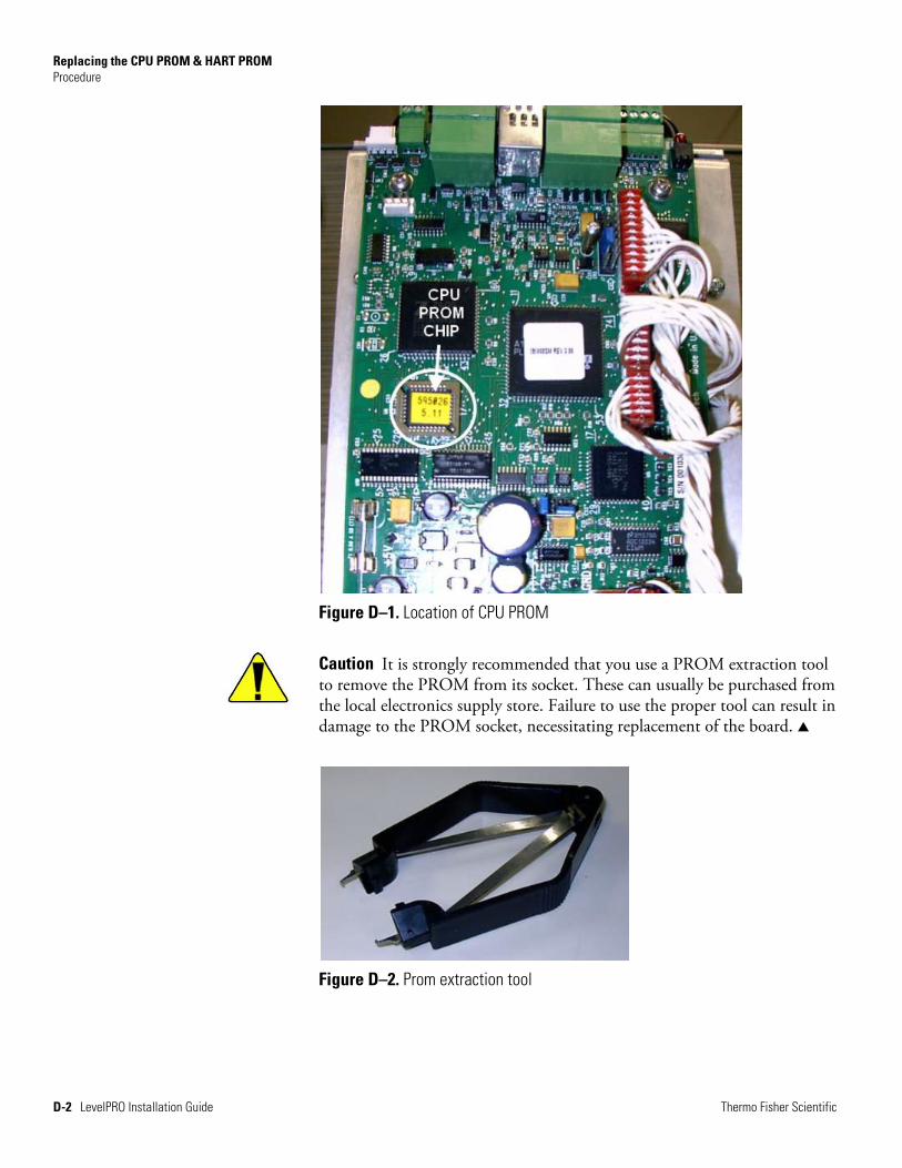
Figure D–1. Location of CPU PROM
Caution It is strongly recommended that you use a PROM extraction tool to remove the PROM from its socket. These can usually be purchased from the local electronics supply store. Failure to use the proper tool can result in damage to the PROM socket, necessitating replacement of the board.
Figure D–2. Prom extraction tool
Replacing the CPU PROM & HART PROM Procedure
Thermo Fisher Scientific LevelPRO Installation Guide D-3
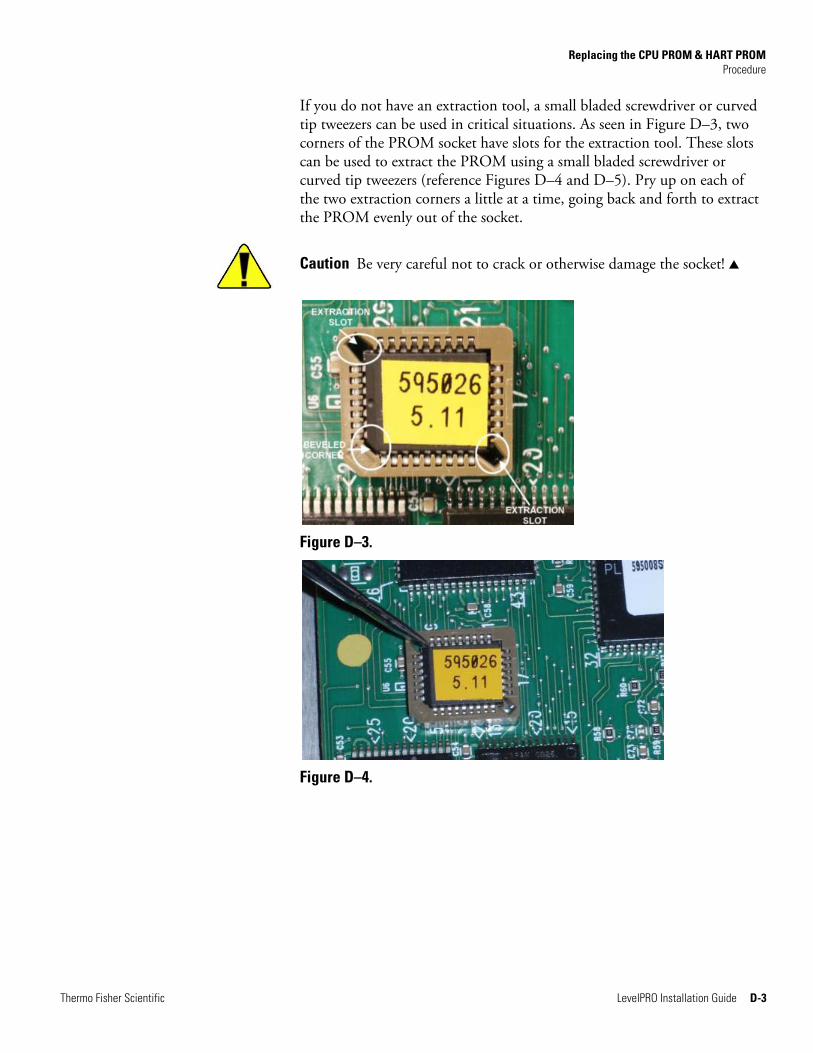
If you do not have an extraction tool, a small bladed screwdriver or curved tip tweezers can be used in critical situations. As seen in Figure D–3, two corners of the PROM socket have slots for the extraction tool. These slots can be used to extract the PROM using a small bladed screwdriver or curved tip tweezers (reference Figures D–4 and D–5). Pry up on each of the two extraction corners a little at a time, going back and forth to extract the PROM evenly out of the socket.
Caution Be very careful not to crack or otherwise damage the socket!
Figure D–3.
Figure D–4.
Replacing the CPU PROM & HART PROM Procedure
D-4 LevelPRO Installation Guide Thermo Fisher Scientific
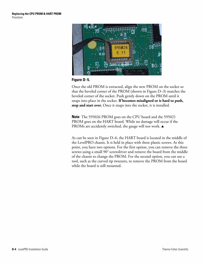
Figure D–5.
Once the old PROM is extracted, align the new PROM on the socket so that the beveled corner of the PROM (shown in Figure D–3) matches the beveled corner of the socket. Push gently down on the PROM until it snaps into place in the socket. If becomes misaligned or is hard to push, stop and start over. Once it snaps into the socket, it is installed.
Note The 595026 PROM goes on the CPU board and the 595021 PROM goes on the HART board. While no damage will occur if the PROMs are accidently switched, the gauge will not work.
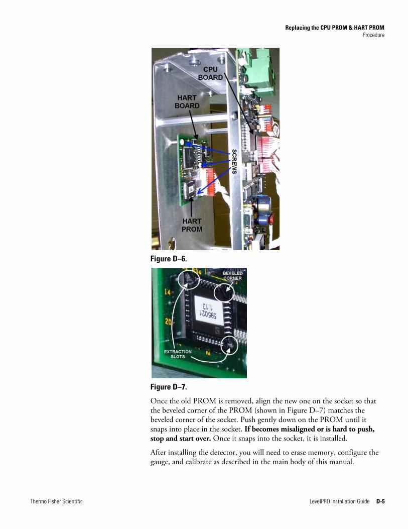
As can be seen in Figure D–6, the HART board is located in the middle of the LevelPRO chassis. It is held in place with three plastic screws. At this point, you have two options. For the first option, you can remove the three screws using a small 90° screwdriver and remove the board from the middle of the chassis to change the PROM. For the second option, you can use a tool, such as the curved tip tweezers, to remove the PROM from the board while the board is still mounted.
Replacing the CPU PROM & HART PROM Procedure
Thermo Fisher Scientific LevelPRO Installation Guide D-5
Figure D–6.
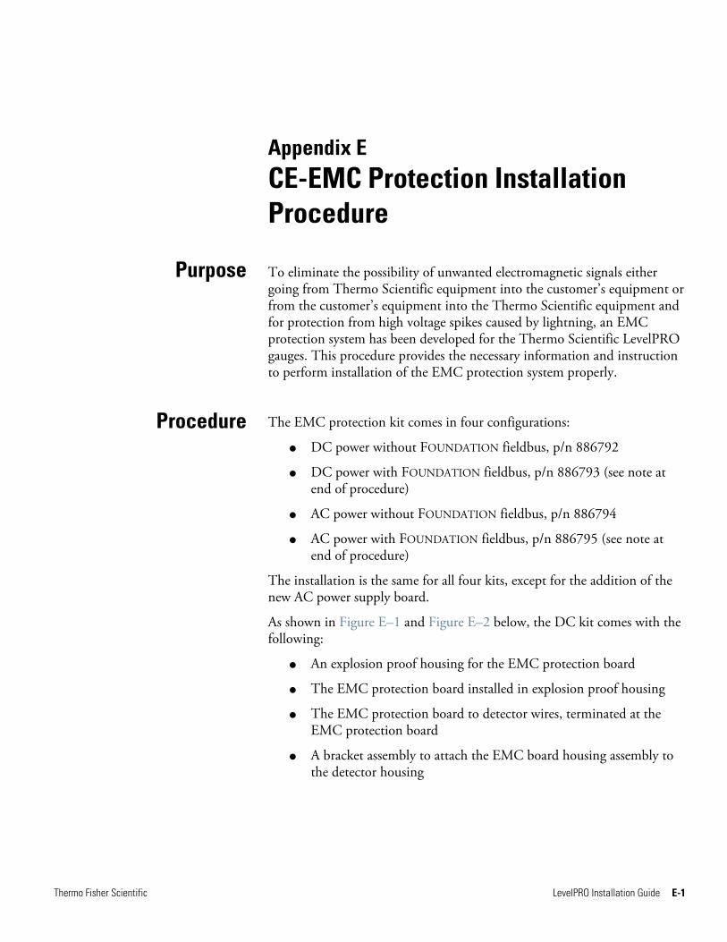
Figure D–7.
Once the old PROM is removed, align the new one on the socket so that the beveled corner of the PROM (shown in Figure D–7) matches the beveled corner of the socket. Push gently down on the PROM until it snaps into place in the socket. If becomes misaligned or is hard to push, stop and start over. Once it snaps into the socket, it is installed.
After installing the detector, you will need to erase memory, configure the gauge, and calibrate as described in the main body of this manual.

This page intentionally left blank.
Thermo Fisher Scientific LevelPRO Installation Guide E-1
Appendix E CE-EMC Protection Installation Procedure
To eliminate the possibility of unwanted electromagnetic signals either going from Thermo Scientific equipment into the customer’s equipment or from the customer’s equipment into the Thermo Scientific equipment and for protection from high voltage spikes caused by lightning, an EMC protection system has been developed for the Thermo Scientific LevelPRO gauges. This procedure provides the necessary information and instruction to perform installation of the EMC protection system properly.
The EMC protection kit comes in four configurations:
DC power without FOUNDATION fieldbus, p/n 886792
DC power with FOUNDATION fieldbus, p/n 886793 (see note at end of procedure)
AC power without FOUNDATION fieldbus, p/n 886794
AC power with FOUNDATION fieldbus, p/n 886795 (see note at end of procedure)
The installation is the same for all four kits, except for the addition of the new AC power supply board.
As shown in Figure E–1 and Figure E–2 below, the DC kit comes with the following:
An explosion proof housing for the EMC protection board
The EMC protection board installed in explosion proof housing
The EMC protection board to detector wires, terminated at the EMC protection board
A bracket assembly to attach the EMC board housing assembly to the detector housing
Purpose
Procedure
CE-EMC Protection Installation Procedure Procedure
E-2 LevelPRO Installation Guide Thermo Fisher Scientific
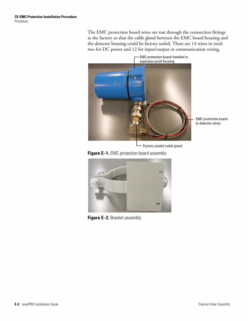
The EMC protection board wires are run through the connection fittings at the factory so that the cable gland between the EMC board housing and the detector housing could be factory sealed. There are 14 wires in total: two for DC power and 12 for input/output or communication wiring.
Figure E–1. EMC protection board assembly
Figure E–2. Bracket assembly
CE-EMC Protection Installation Procedure Installation
Thermo Fisher Scientific LevelPRO Installation Guide E-3
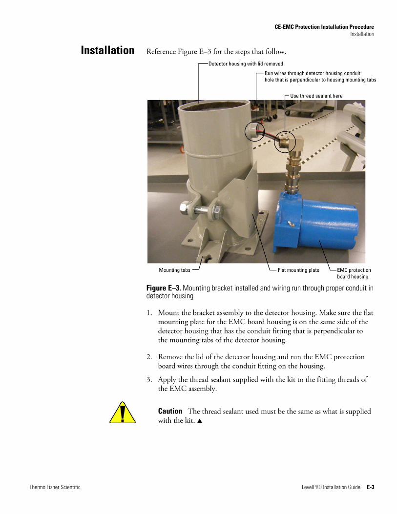
Reference Figure E–3 for the steps that follow.
Figure E–3. Mounting bracket installed and wiring run through proper conduit in detector housing
1. Mount the bracket assembly to the detector housing. Make sure the flat mounting plate for the EMC board housing is on the same side of the detector housing that has the conduit fitting that is perpendicular to the mounting tabs of the detector housing.
2. Remove the lid of the detector housing and run the EMC protection board wires through the conduit fitting on the housing.
3. Apply the thread sealant supplied with the kit to the fitting threads of the EMC assembly.
Caution The thread sealant used must be the same as what is supplied with the kit.
Installation
CE-EMC Protection Installation Procedure Installation
E-4 LevelPRO Installation Guide Thermo Fisher Scientific
4. Using the appropriate tool, screw the EMC assembly onto the detector housing approximately six to seven rotations (see note) until the connection is tight and the mounting holes of the EMC board housing align with the holes in the mounting plate of the bracket assembly. Be sure to rotate the wires that are inserted into the detector housing as the EMC assembly is rotated to keep from damaging the wires.
Note In order to maintain area protection, a minimum engagement of five threads is required.
5. Due to variances in components, extra nuts and washers have been included in the kit to use as spacers between the EMC board enclosure and the mounting plate. When the EMC assembly conduit fitting is threaded into the detector housing so that the connection is secure, use the extra nuts and washers to fill in any gap that may still exist and tighten the mounting bolts.
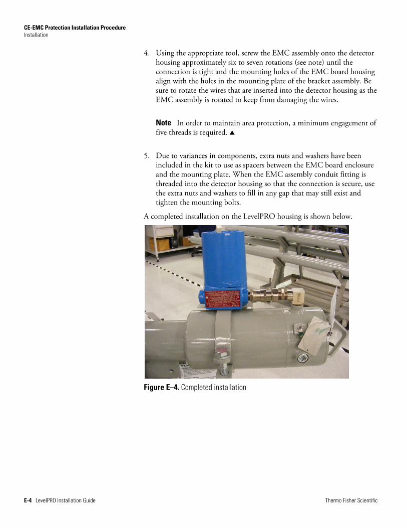
A completed installation on the LevelPRO housing is shown below.
Figure E–4. Completed installation
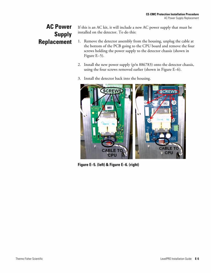
CE-EMC Protection Installation Procedure AC Power Supply Replacement
Thermo Fisher Scientific LevelPRO Installation Guide E-5
If this is an AC kit, it will include a new AC power supply that must be installed on the detector. To do this:
1. Remove the detector assembly from the housing, unplug the cable at the bottom of the PCB going to the CPU board and remove the four screws holding the power supply to the detector chassis (shown in Figure E–5).
2. Install the new power supply (p/n 886783) onto the detector chassis, using the four screws removed earlier (shown in Figure E–6).
3. Install the detector back into the housing.
Figure E–5. (left) & Figure E–6. (right)
AC Power Supply
Replacement
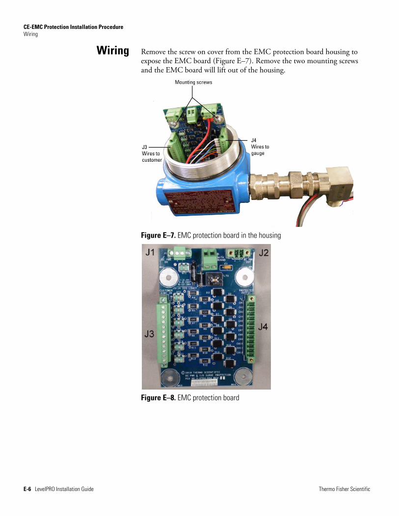
CE-EMC Protection Installation Procedure Wiring
E-6 LevelPRO Installation Guide Thermo Fisher Scientific
Remove the screw on cover from the EMC protection board housing to expose the EMC board (Figure E–7). Remove the two mounting screws and the EMC board will lift out of the housing.
Figure E–7. EMC protection board in the housing
Figure E–8. EMC protection board
Wiring
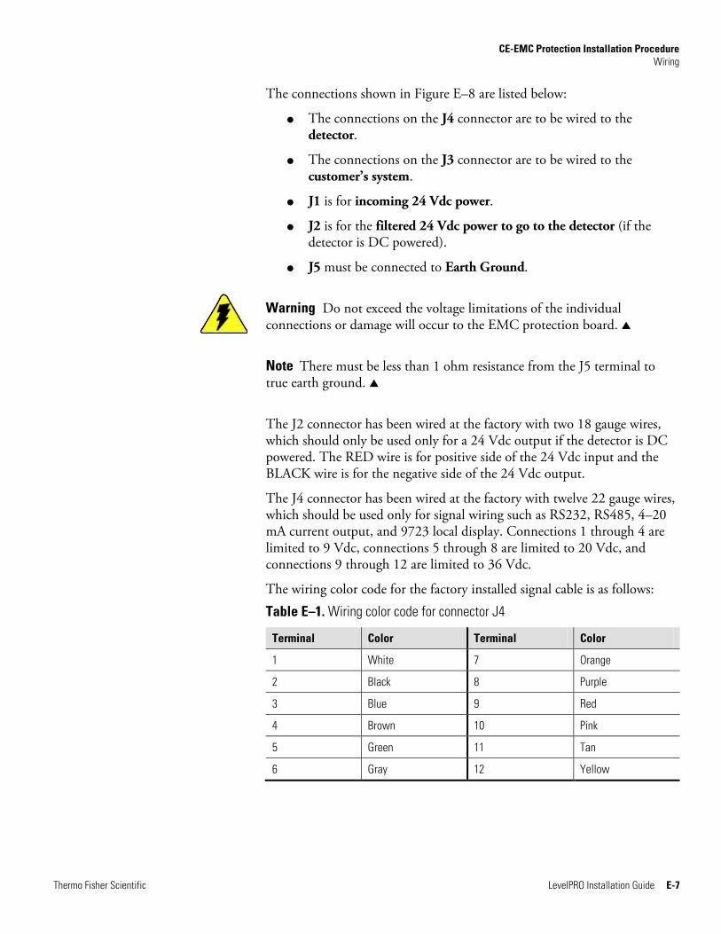
CE-EMC Protection Installation Procedure Wiring
Thermo Fisher Scientific LevelPRO Installation Guide E-7
The connections shown in Figure E–8 are listed below:
The connections on the J4 connector are to be wired to the detector.
The connections on the J3 connector are to be wired to the customer’s system.
J1 is for incoming 24 Vdc power.
J2 is for the filtered 24 Vdc power to go to the detector (if the detector is DC powered).
J5 must be connected to Earth Ground.
Warning Do not exceed the voltage limitations of the individual connections or damage will occur to the EMC protection board.
Note There must be less than 1 ohm resistance from the J5 terminal to true earth ground.
The J2 connector has been wired at the factory with two 18 gauge wires, which should only be used only for a 24 Vdc output if the detector is DC powered. The RED wire is for positive side of the 24 Vdc input and the BLACK wire is for the negative side of the 24 Vdc output.
The J4 connector has been wired at the factory with twelve 22 gauge wires, which should be used only for signal wiring such as RS232, RS485, 4–20 mA current output, and 9723 local display. Connections 1 through 4 are limited to 9 Vdc, connections 5 through 8 are limited to 20 Vdc, and connections 9 through 12 are limited to 36 Vdc.
The wiring color code for the factory installed signal cable is as follows:
Table E–1. Wiring color code for connector J4
Terminal Color Terminal Color
1 White 7 Orange
2 Black 8 Purple
3 Blue 9 Red
4 Brown 10 Pink
5 Green 11 Tan
6 Gray 12 Yellow
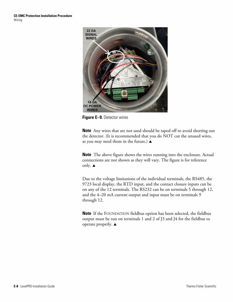
CE-EMC Protection Installation Procedure Wiring
E-8 LevelPRO Installation Guide Thermo Fisher Scientific
Figure E–9. Detector wires
Note Any wires that are not used should be taped off to avoid shorting out the detector. (It is recommended that you do NOT cut the unused wires, as you may need them in the future.)
Note The above figure shows the wires running into the enclosure. Actual connections are not shown as they will vary. The figure is for reference only.
Due to the voltage limitations of the individual terminals, the RS485, the 9723 local display, the RTD input, and the contact closure inputs can be on any of the 12 terminals. The RS232 can be on terminals 5 through 12, and the 4–20 mA current output and input must be on terminals 9 through 12.
Note If the FOUNDATION fieldbus option has been selected, the fieldbus output must be run on terminals 1 and 2 of J3 and J4 for the fieldbus to operate properly.
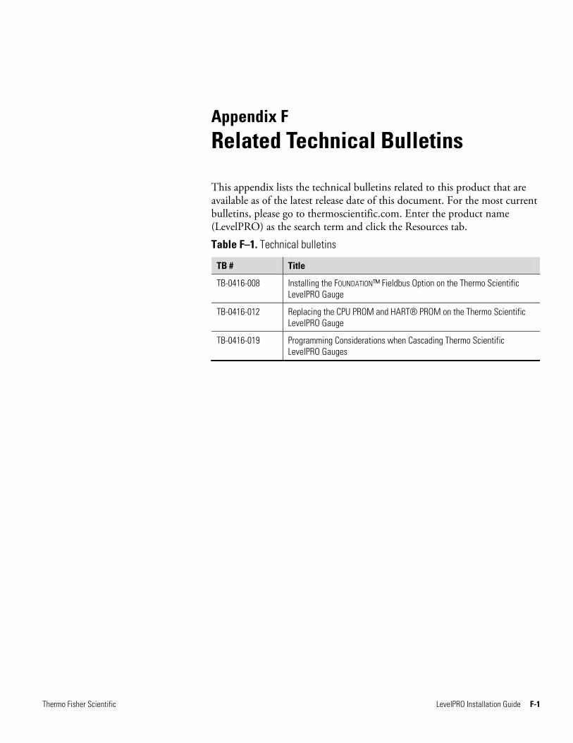
Thermo Fisher Scientific LevelPRO Installation Guide F-1
Appendix F Related Technical Bulletins
This appendix lists the technical bulletins related to this product that are available as of the latest release date of this document. For the most current bulletins, please go to thermoscientific.com. Enter the product name (LevelPRO) as the search term and click the Resources tab.
Table F–1. Technical bulletins
TB # Title
TB-0416-008 Installing the FOUNDATION™ Fieldbus Option on the Thermo Scientific LevelPRO Gauge
TB-0416-012 Replacing the CPU PROM and HART® PROM on the Thermo Scientific LevelPRO Gauge
TB-0416-019 Programming Considerations when Cascading Thermo Scientific LevelPRO Gauges

This page intentionally left blank.
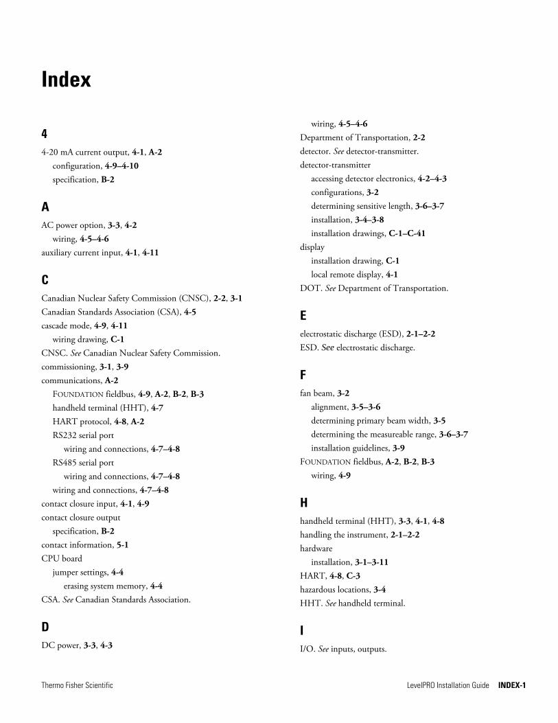
Thermo Fisher Scientific LevelPRO Installation Guide INDEX-1
Index
4 4-20 mA current output, 4-1, A-2
configuration, 4-9–4-10 specification, B-2
A AC power option, 3-3, 4-2
wiring, 4-5–4-6 auxiliary current input, 4-1, 4-11
C Canadian Nuclear Safety Commission (CNSC), 2-2, 3-1 Canadian Standards Association (CSA), 4-5 cascade mode, 4-9, 4-11
wiring drawing, C-1 CNSC. See Canadian Nuclear Safety Commission. commissioning, 3-1, 3-9 communications, A-2
FOUNDATION fieldbus, 4-9, A-2, B-2, B-3 handheld terminal (HHT), 4-7 HART protocol, 4-8, A-2 RS232 serial port
wiring and connections, 4-7–4-8 RS485 serial port
wiring and connections, 4-7–4-8 wiring and connections, 4-7–4-8
contact closure input, 4-1, 4-9 contact closure output
specification, B-2 contact information, 5-1 CPU board
jumper settings, 4-4 erasing system memory, 4-4
CSA. See Canadian Standards Association.
D DC power, 3-3, 4-3
wiring, 4-5–4-6 Department of Transportation, 2-2 detector. See detector-transmitter. detector-transmitter
accessing detector electronics, 4-2–4-3 configurations, 3-2 determining sensitive length, 3-6–3-7 installation, 3-4–3-8 installation drawings, C-1–C-41
display installation drawing, C-1 local remote display, 4-1
DOT. See Department of Transportation.
E electrostatic discharge (ESD), 2-1–2-2 ESD. See electrostatic discharge.
F fan beam, 3-2
alignment, 3-5–3-6 determining primary beam width, 3-5 determining the measureable range, 3-6–3-7 installation guidelines, 3-9
FOUNDATION fieldbus, A-2, B-2, B-3 wiring, 4-9
H handheld terminal (HHT), 3-3, 4-1, 4-8 handling the instrument, 2-1–2-2 hardware
installation, 3-1–3-11 HART, 4-8, C-3 hazardous locations, 3-4 HHT. See handheld terminal.
I I/O. See inputs, outputs.

Index
INDEX-2 LevelPRO Installation Guide Thermo Fisher Scientific
inputs auxiliary current, 4-1, 4-11 contact closure, 4-1, 4-9 specification, B-2
installation commissioning, 3-1 detector-transmitter, 3-4–3-8 drawings, C-1–C-41 guidelines, 3-2–3-3
for determining measurable range, 3-6–3-7 for determining source beam alignment, 3-5–3-6 for mounting the source housing, 3-8–3-10
hardware, 3-1–3-11 hazardous locations, 3-4 multiple detectors/source housings, 3-11 planning, 3-3
determining measurable range, 3-6–3-7 determining source beam alignment, 3-5–3-6
safety, 3-1, 3-2, 3-4 shutter actuator, 3-10 source housing, 3-8–3-10, 3-8–3-10 system power requirements, 3-3 system wiring, 4-1–4-11
installing commissioning, 3-1 detector-transmitter, 3-4–3-8 determining measurable range, 3-6–3-7, 3-6–3-7 drawings, C-1–C-41 guidelines for, 3-2–3-3
determining measurable range, 3-6–3-7 determining source beam alignment, 3-5–3-6 mounting the source housing, 3-8–3-10
hardware, 3-1–3-11 in hazardous locations, 3-4 multiple detectors/source housings, 3-11 planning, 3-3
determining measurable range, 3-6–3-7 determining source beam alignment, 3-5–3-6 for source housing mounting, 3-8–3-10
safety, 3-1, 3-2, 3-4 shutter actuator, 3-10 source housing, 3-8–3-10 system power requirements, 3-3
system wiring, 4-1–4-11
J jumper settings
CPU configuration, 4-4
L licensing, 3-1, 3-9
M Model 9734. See handheld terminal (HHT). mounting. See installing or installation.
O ordering information, A-1–A-2 OSHA, 2-2 outputs, A-2
4-20 mA current, 4-1, 4-9, B-2 contact closure, B-2
P party-line communications, 4-7 power, A-1
supply wiring, 4-5–4-6 system requirements, 3-3
R radiation beam. See source. receiving the instrument. See handling the instrument. relay option, 4-1, 4-6, A-2 RS232 serial port
wiring and connections, 4-7–4-8 RS485 serial port
installation drawing, C-1 party-line setup, 4-7 wiring and connections, 4-7–4-8
S safety, ix–x, 3-1, 3-2, 3-4, 4-1, 4-2, 4-5, 4-6 sensitive length of detector, 3-6–3-7 shipping the instrument. See handling the instrument.
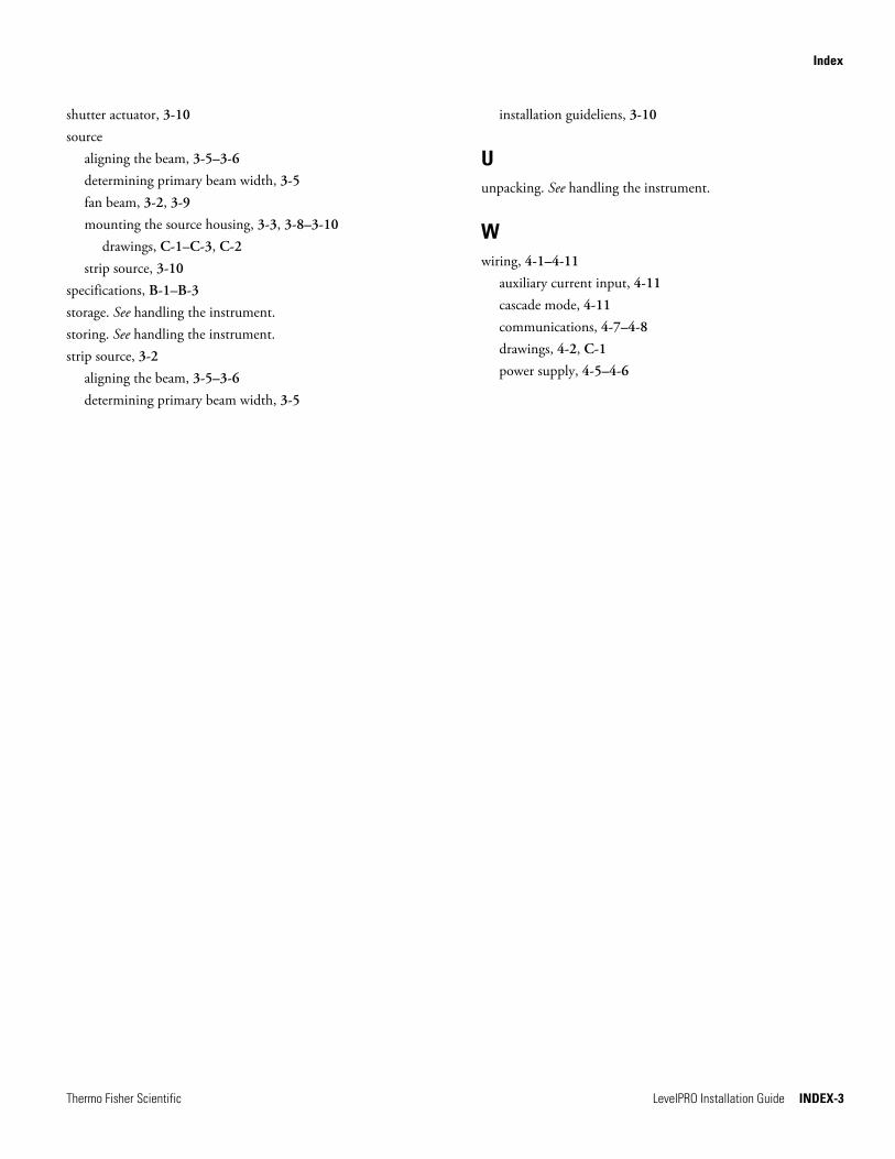
Index
Thermo Fisher Scientific LevelPRO Installation Guide INDEX-3
shutter actuator, 3-10 source
aligning the beam, 3-5–3-6 determining primary beam width, 3-5 fan beam, 3-2, 3-9 mounting the source housing, 3-3, 3-8–3-10
drawings, C-1–C-3, C-2 strip source, 3-10
specifications, B-1–B-3 storage. See handling the instrument. storing. See handling the instrument. strip source, 3-2
aligning the beam, 3-5–3-6 determining primary beam width, 3-5
installation guideliens, 3-10
U unpacking. See handling the instrument.
W wiring, 4-1–4-11
auxiliary current input, 4-11 cascade mode, 4-11 communications, 4-7–4-8 drawings, 4-2, C-1 power supply, 4-5–4-6

This page intentionally left blank.

Thermo Fisher Scientific81 Wyman StreetP.O. Box 9046Waltham, Massachusetts 02454-9046United States
www.thermofisher.com