Embed Size (px)
Citation preview
WYLER AG Im Hölderli CH-8405 WINTERTHUR Switzerland
Tel. 0041 (0) 52 233 66 66 Fax. 0041 (0) 52 233 20 53 Homepage: http://www.wylerag.com E-Mail: [email protected]
OPERATOR'S MANUAL
LEVELTRONIC „classic“ and “NT”
MINILEVEL “classic” and “NT”
LEVELMETER 25 / C25 LEVELMETER 2000
File: „nt_eng.doc“ 25.7.1999
Page 2 of 42 pages
Content SUBJECT
Page
INDEX 3 1. BASICS 6 1.1. Instrument's overview 6 1.2. Measuring instruments / External display instruments 7 1.3. Measuring procedure / general use 8 1.3.1 Basic set-up of the inclination measuring instruments / plus - minus rule 8 1.3.2 Absolute measurement / Relative measurement / Differential measurement 9 1.3.3 General remarks about "ANGLES" 10 1.3.4 Height related to the step length 11 1.4. Zero setting by reversal measurement (Absolute ZERO) 12 1.5. Applications 12 1.5.1 Measuring absolute 12 1.5.2 Measuring relative 12 1.5.3 Differential respectively reference measurement using an engineer set 13 1.5.4 Angular measurements 15 1.5.5 Lines and flatness measurement (manual procedure) 16 1.6. WYLER software LEVELSOFT 17 2. DETAILED INFORMATION to the various instruments 19 2.1. MINILEVEL / LEVELTRONIC „classic“ 19 2.1.1 MINILEVEL “classic” A10 / LEVELMETER C25/DC (red cover) 19 2.1.2 LEVELMETER C25 / DC 20 2.1.3 LEVELTRONIC “classic” A40 / LEVELMETER 25 (blue cover) 22 2.1.4 LEVELMETER 25 22 2.2. MINILEVEL / LEVELTRONIC „NT“ 24 2.2.1 MINILEVEL “NT” 11 / LEVELMETER C25 (red cover) or
LEVELMETER 2000 24
2.2.2 LEVELMETER C25/DC 25 2.2.3 LEVELMETER 2000 26 2.2.4 LEVELTRONIC “NT” 41 with LEVELMETER C25/DC (red cover) or
LEVELMETER 2000 31
2.2.5 LEVELMETER C25/DC 32 2.2.6 LEVELMETER 2000 33 3. TECHNICAL DATA 38 3.1. LEVELTRONIC “classic” / A40 38 3.2. LEVELTRONIC “NT” / 41 38 3.3. MINILEVEL “classic” / A10 38 3.4. MINILEVEL “NT” / 11 39 4. MAINTENANCE 39 4.1. Easily cured difficulties 39 5. ACCESSORIES / SPARE PARTS 41 6. STORING Instruments / Care and handling of the batteries 41/42 7. REPAIR OF MEASURING INSTRUMENTS 42 Änderungen / Modifications:
Datum / Date Geändert durch Modified by
Beschreibung der Änderung Description of modifications
5.9.2000 HEH Fig. 9 / Seite 11 neu 27.3.2001 HEH Data collection using ENTER key 10.1.2003 HEH/MO Index included, Levelsoft PRO, deactivation autom. shut off 2.4.2003 HEH New:Express Repair Service
Page 3 of 42 pages
INDEX Key word Chapter Page
A Absolute measurement / Relative measurement / Differential measurement 1.3.2 9 Absolute ZERO, Zero setting by reversal measurement 1.4 12 ACCESSORIES / SPARE PARTS 5 41 Analogue data transmission 29 Angle / Inclination 1.3.3 10 Angles 90°, 1.5.4 15 Angular error of the instrument 1.5.4 15
B Basic set-up of the inclination measuring instruments / plus - minus rule 1.3.1 8 Basics 1 6 Battery change / Battery check LEVELMETER 25 2.1.4 22 Battery / Care and handling of the batteries 6.2 42
C Change of Measuring Unit, LM 2000, with Leveltronic “NT” 2.2.6.7 34 Change of Measuring Unit, with Minilevel “NT” 2.2.3.7 27 Classic, Instruments 1.1 6 Collecting the data from a LM 2000 to a PC when using WYLER sw LEVELSOFT 2.2.3.8 28 Collecting the data from a LM 2000 to a PC when using WYLER sw LEVELSOFT 2.2.6.8 35 Configurations possible with LEVELTRONIC „NT“ 41 36 Configurations with LEVELTRONIC „classic“ 2.1.3 22 Configurations with MINILEVEL „classic“ 2.1.2 20
D Detailed information to the various instruments 2 19 Differences between LEVELMETER 25, C25 and LEVELMETER 2000, general 1.2 7 Differences between Minilevel / Leveltronic concerning the display 1.2 7 Differential measurement 1.3.2 9 Differential Measurement with Levelmeter 2000 / Minilevel “NT” 2.2.3.3 26 Differential Measurement with relative Zero, LM 2000, with Leveltronic “NT” 2.2.6.6 34 Differential Measurement with Relative Zero, with Minilevel “NT” 2.2.3.6 27 Differential Measurement, LM 2000 with Leveltronic “NT” 2.2.6.3 33 Differential respectively reference measurement using an engineer set 1.5.3 13 Digital data transmission (RS485) 29 Disabling the automatic shut-off of the LEVELMETER 2000 2.2.3.9 28 Disabling the automatic shut-off of the LEVELMETER 2000 2.2.6.9 35
E Engineer set 1.5.3 13 Engineer set 2 Leveltronic NT 41 with LEVELMETER 2000 1.1 6 Engineer set with 2 Leveltronic A40 „classic“ and LEVELMETER 25/AC 1.1 6 Examples for differential / reference measurement 1.5.3 13 Express Repair Service, ERS 7 42 External display unit./ Instruments 1.2 7
F Flatness measurement (manual procedure) 1.5.5 16 Flatness measurement of partial surfaces 1.6 17 Flatness measurement of surfaces 1.6 17 Flatness measurement software LEVELSOFT PRO of WYLER AG 1.2 7 Flatness of a surface plate 1.3.1 8 Function check of the MINILEVEL „classic“ combined with LEVELMETER C25 2.1.2 20
G General remarks about "ANGLES" 1.3.3 10 General use / measuring procedure 1.3 8 Guide ways of machine beds 1.5.3 13
H Height related to the step length 1.3.4 11
Page 4 of 42 pages
I
Inclination / Angle 1.3.3 10 Inserting the battery in LEVELTRONIC “NT” 41 31 Instruments / external display 1.2 7 Instrument's overview 1.1 6 ISO 1101 1.6 17
L LEVELMETER 2000, with Leveltronic “NT” 2.2.6 33 LEVELMETER 25 and LEVELTRONIC “classic” A40 2.1.3 22 LEVELMETER C25 / DC with Minilevel “classic” 2.1.2 20 LEVELMETER C25/DC with Minilevel / Leveltronic “NT” 2.2.5 32 LEVELMETER C25/DC with Minilevel “ / Leveltronic NT” 2.2.2 25 LEVELMETER 2000 with Minilevel “NT” 2.2.3 26 LEVELMETER 2000, overview 1.2 7 LEVELSOFT PRO, WYLER software 1.6 17 LEVELTRONIC “classic” / A40 3.1 38 LEVELTRONIC “classic” A40 / LEVELMETER 25 2.1.4 22 LEVELTRONIC “NT” / 41 3.2 38 LEVELTRONIC “NT” 41 with LEVELMETER C25/DC (red cover) or LM2000 2.2.4 31 LEVELTRONIC „NT“ / MINILEVEL 2.2 24 Leveltronic NT 41 with LEVELMETER 2000 1.1 6 LEVELTRONIC NT 41 with LEVELMETER C25/DC 1.2 7 Lines and flatness measurement (manual procedure) 1.5.5 16 Lines with twist 1.6 17 Lines, straightness 1.6 17
M MAINTENANCE 4 39 Malfunctions, easily cured difficulties 4.1 39 Measurement absolute with Levelmeter 2000 / Minilevel “NT” 2.2.3.2 26 Measurement absolute, LM 2000 with Leveltronic “NT” 2.2.6.2 33 Measurement on machine tools 1.6 17 Measuring procedure / general use 1.3 8 Measuring with relative Zero, with Leveltronic “NT” 2.2.6.5 34 Measuring with relative Zero, with Minilevel “NT” 2.2.3.5 27 MINILEVEL / LEVELTRONIC „NT“ 2.2 24 MINILEVEL “classic” / A10 3.3 38 MINILEVEL “classic” A10 / LEVELMETER C25/DC 2.1.1 19 MINILEVEL “NT” / 11 3.4 39 MINILEVEL “NT” 11 / LEVELMETER C25 (red cover) or LEVELMETER 2000 2.2.1 24 MINILEVEL „NT“ 11, possible configurations 29 Minilevel A10 „classic“ 1.1 6 Minilevel A10 „classic“ 1.1 6 Minilevel NT 11 with integrated display 1.1 6 mm/m and µm/m 1.3.3 10
N NT Series, Instruments 1.1 6
P Parallelism 1.6 17 Plus - minus rule 1.3.1 9
R Rectangularity 1.6 17 Reference instrument 1.3.2 9 Reference, respectively differential measurement using an engineer set 1.5.3 13 Relative measurement 1.3.2 9 Repair of Measuring Instruments 7 42 Reversal measurement 1.4 12
Page 5 of 42 pages
S
Sensitivity of the instrument 1.5.5 16 Small angles 1.5.4 15 SPARE PARTS / ACCESSORIES / 5 41 Square angles 1.5.4 15 Start the LEVELMETER 2000 2.2.3.1 26 Start the LEVELMETER 2000, with Leveltronic “NT” 2.2.6.1 33 STORING 6.1 41 Switch off the Levelmeter 2000 2.2.6.9 35 Switch the Levelmeter 2000 off 2.2.3.9 28
T TECHNICAL DATA 3 38
U UNION JACK 1.6 17
Z Zero setting (absolute ZERO) LEVELTRONIC „NT“ 41 with LEVELMETER C25/DC 36 Zero Setting (absolute) of LT „NT“ 41 with LM 2000 by reversal measurement 38 ZERO Setting (absolute), reversal measurement, LM 2000 with Leveltronic “NT” 2.2.6.4 33 Zero setting by reversal measurement, Absolute ZERO 1.4 12 Zero setting of MINILEVEL „NT“ 11 with LEVELMETER C25/DC 2.2.3 26 ZERO Setting, absolute, reversal measurement with Levelmeter 2000/Minilevel “NT” 2.2.3.4 26
Page 6 of 42 pages
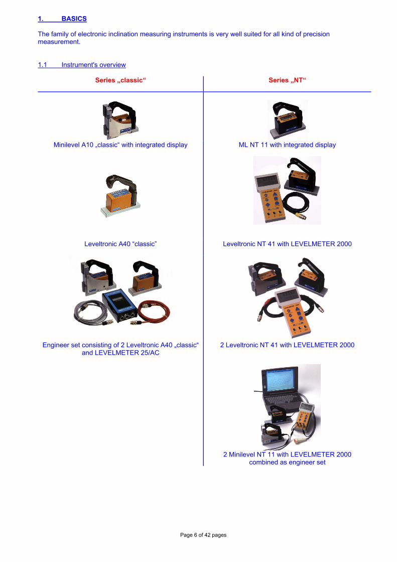
1. BASICS The family of electronic inclination measuring instruments is very well suited for all kind of precision measurement. 1.1 Instrument's overview
Series „classic“
Series „NT“
Minilevel A10 „classic“ with integrated display
ML NT 11 with integrated display
Leveltronic A40 “classic”
Leveltronic NT 41 with LEVELMETER 2000
Engineer set consisting of 2 Leveltronic A40 „classic“ and LEVELMETER 25/AC
2 Leveltronic NT 41 with LEVELMETER 2000
2 Minilevel NT 11 with LEVELMETER 2000
combined as engineer set
Page 7 of 42 pages
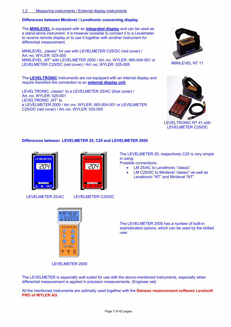
1.2 Measuring instruments / External display instruments Differences between Minilevel / Leveltronic concerning display. The MINILEVEL is equipped with an integrated display and can be used as a stand-alone instrument. It is however possible to connect it to a Levelmeter to receive remote display or to use it together with another instrument for differential measurement. MINILEVEL „classic“ for use with LEVELMETER C25/DC (red cover) / Art.-no. WYLER: 025-005 MINILEVEL „NT“ with LEVELMETER 2000 / Art.-no. WYLER: 065-004-001 or LEVELMETER C25/DC (red cover) / Art.-no. WYLER: 025-005
MINILEVEL NT 11
The LEVELTRONIC instruments are not equipped with an internal display and require therefore the connection to an external display unit. LEVELTRONIC „classic“ to a LEVELMETER 25/AC (blue cover) / Art.-no. WYLER: 025-001 LEVELTRONIC „NT“ to a LEVELMETER 2000 / Art.-no. WYLER: 065-004-001 or LEVELMETER C25/DC (red cover) / Art.-no. WYLER: 025-005
LEVELTRONIC NT 41 with
LEVELMETER C25/DC Differences between LEVELMETER 25, C25 and LEVELMETER 2000
LEVELMETER 25/AC
LEVELMETER C25/DC
The LEVELMETER 25, respectively C25 is very simple in using. Possible connections:
• LM 25/AC to Leveltronic “classic” • LM C25/DC to Minilevel “classic” as well as
Leveltronic “NT” and Minilevel “NT”
LEVELMETER 2000
The LEVELMETER 2000 has a number of built-in sophisticated options, which can be used by the skilled user.
The LEVELMETER is especially well suited for use with the above-mentioned instruments, especially when differential measurement is applied in precision measurements. (Engineer set) All the mentioned instruments are optimally used together with the flatness measurement software Levelsoft PRO of WYLER AG
Page 8 of 42 pages
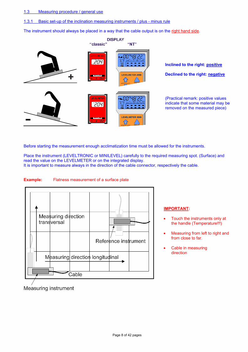
1.3 Measuring procedure / general use 1.3.1 Basic set-up of the inclination measuring instruments / plus - minus rule The instrument should always be placed in a way that the cable output is on the right hand side.
Inclined to the right: positive Declined to the right: negative
(Practical remark: positive values indicate that some material may be removed on the measured piece)
Before starting the measurement enough acclimatization time must be allowed for the instruments. Place the instrument (LEVELTRONIC or MINILEVEL) carefully to the required measuring spot. (Surface) and read the value on the LEVELMETER or on the integrated display. It is important to measure always in the direction of the cable connector, respectively the cable. Example: Flatness measurement of a surface plate
IMPORTANT: • Touch the instruments only at
the handle (Temperature!!!) • Measuring from left to right and
from close to far.
• Cable in measuring direction
Page 9 of 42 pages
1.3.2 Absolute measurement / Relative measurement / Differential measurement Absolute measurement
(Absolute ZERO) Condition for the absolute measurement is the performing of a reversal measurement for determining the absolute zero (to the centre of the earth) After this procedure the instrument will display the effective deviation from the centre of gravity. This means the value is an absolute angle of the measured surface. Example: if the object to be measured is absolutely level, the display is "0"
Relative measurement (Relative ZERO) A number of measurements do not require the absolute ZERO as described above.
Example: Angular deviation between two objects. (Lines, surfaces, guide ways) The
measurement instrument is placed on an object and the displayed value is changed to "0". Then the instrument is relocated to a second object and the displayed value of the angle is the angular difference between the two surfaces. If the display is also "0", then both surfaces are parallel. Most important is that always the instrument is placed on both positions in the same direction.
Differential measurement
A differential measurement is a measurement with two instruments Measuring instrument (A) and Reference instrument (B), measuring the angular difference between the two. This means e.g. if the angular change in both instruments is the same the displayed value (Difference A - B) does not change. In principle this is a special relative measurement. I the following measuring tasks the differential measurement is especially used
• Measurement on object with vibrations imposed. • Measurements on unstable systems or objects
Example: Measuring the flatness of a machine bed. The reference instrument is
placed on a stable part of the machine where the measurement is not interfered. With the measuring instrument the measurement is taking place without removing the reference instrument.
Page 10 of 42 pages
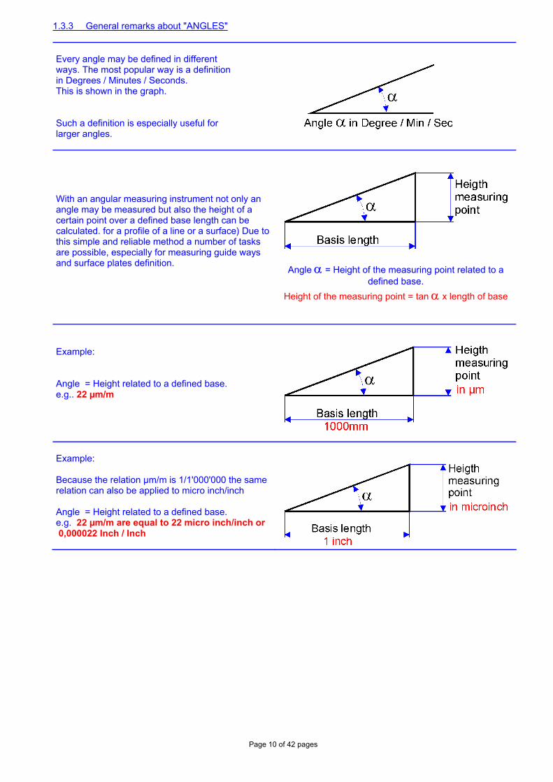
1.3.3 General remarks about "ANGLES" Every angle may be defined in different ways. The most popular way is a definition in Degrees / Minutes / Seconds. This is shown in the graph. Such a definition is especially useful for larger angles.
With an angular measuring instrument not only an angle may be measured but also the height of a certain point over a defined base length can be calculated. for a profile of a line or a surface) Due to this simple and reliable method a number of tasks are possible, especially for measuring guide ways and surface plates definition.
Angle α = Height of the measuring point related to a defined base.
Height of the measuring point = tan α x length of base
Example: Angle = Height related to a defined base. e.g.. 22 µm/m
Example: Because the relation µm/m is 1/1'000'000 the same relation can also be applied to micro inch/inch Angle = Height related to a defined base. e.g. 22 µm/m are equal to 22 micro inch/inch or 0,000022 Inch / Inch
Page 11 of 42 pages
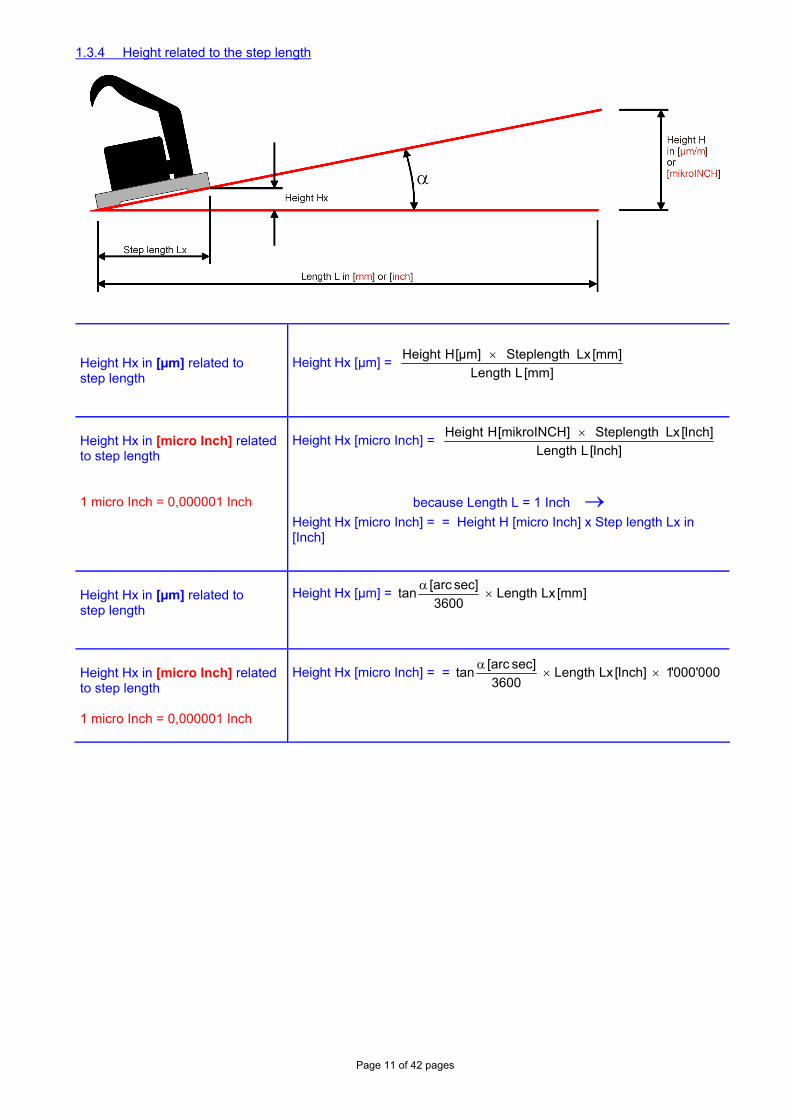
1.3.4 Height related to the step length
Height Hx in [µm] related to step length
Height Hx [µm] = ]mm[LLength
]mm[LxSteplength]µm[HHeight ×
Height Hx in [micro Inch] related to step length 1 micro Inch = 0,000001 Inch
Height Hx [micro Inch] = ]Inch[LLength
]Inch[LxSteplength]mikroINCH[HHeight ×
because Length L = 1 Inch →
Height Hx [micro Inch] = = Height H [micro Inch] x Step length Lx in [Inch]
Height Hx in [µm] related to step length
Height Hx [µm] = ]mm[LxLength3600
sec]arc[tan ×
α
Height Hx in [micro Inch] related to step length 1 micro Inch = 0,000001 Inch
Height Hx [micro Inch] = = 000'000'1]Inch[LxLength3600
sec]arc[tan ××
α
Page 12 of 42 pages
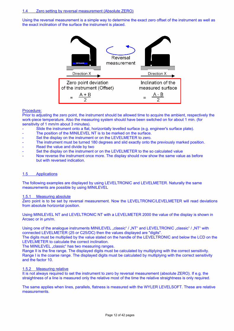
1.4 Zero setting by reversal measurement (Absolute ZERO) Using the reversal measurement is a simple way to determine the exact zero offset of the instrument as well as the exact inclination of the surface the instrument is placed.
Procedure: Prior to adjusting the zero point, the instrument should be allowed time to acquire the ambient, respectively the work-piece temperature. Also the measuring system should have been switched on for about 1 min. (for sensitivity of 1 mm/m about 3 minutes). - Slide the instrument onto a flat, horizontally levelled surface (e.g. engineer's surface plate). - The position of the MINILEVEL NT is to be marked on the surface. - Set the display on the instrument or on the LEVELMETER to zero. - The instrument must be turned 180 degrees and slid exactly onto the previously marked position. - Read the value and divide by two - Set the display on the instrument or on the LEVELMETER to the so calculated value - Now reverse the instrument once more. The display should now show the same value as before but with reversed indication. 1.5 Applications The following examples are displayed by using LEVELTRONIC and LEVELMETER. Naturally the same measurements are possible by using MINILEVEL 1.5.1 Measuring absolute Zero point is to be set by reversal measurement. Now the LEVELTRONIC/LEVELMETER will read deviations from absolute horizontal position. Using MINILEVEL NT and LEVELTRONIC NT with a LEVELMETER 2000 the value of the display is shown in Arcsec or in µm/m. Using one of the analogue instruments MINILEVEL „classic“ / „NT“ and LEVELTRONIC „classic“ / „NT“ with connected LEVELMETER (25 or C25/DC) then the values displayed are "digits". The digits must be multiplied by the value stated on the handle of the LEVELTRONIC and below the LCD on the LEVELMETER to calculate the correct inclination. The MINILEVEL „classic“ has two measuring ranges. Range II is the fine range. The displayed digits must be calculated by multiplying with the correct sensitivity. Range I is the coarse range. The displayed digits must be calculated by multiplying with the correct sensitivity and the factor 10. 1.5.2 Measuring relative It is not always required to set the instrument to zero by reversal measurement (absolute ZERO). If e.g. the straightness of a line is measured only the relative most of the time the relative straightness is only required. The same applies when lines, parallels, flatness is measured with the WYLER LEVELSOFT. These are relative measurements.
Page 13 of 42 pages
1.5.3 Differential respectively reference measurement using an engineer set Such a measurement is useful or necessary if some of the following cases:
• Measurement on object with vibrations imposed. • The inclination of the object to be measured will change by the weight of the instrument • The floor is unstable (heavy loads in the close surroundings • The relative pitch and roll on a machine must be measured.
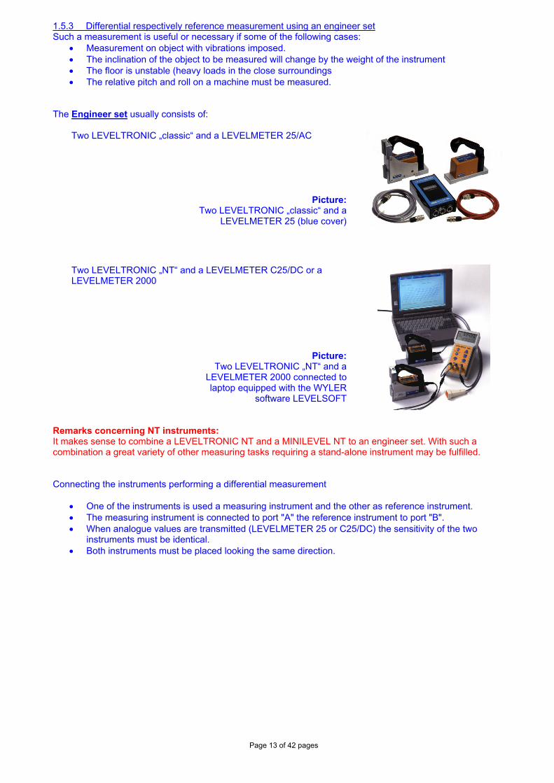
The Engineer set usually consists of:
Two LEVELTRONIC „classic“ and a LEVELMETER 25/AC
Picture:Two LEVELTRONIC „classic“ and a
LEVELMETER 25 (blue cover)
Two LEVELTRONIC „NT“ and a LEVELMETER C25/DC or a LEVELMETER 2000
Picture:Two LEVELTRONIC „NT“ and a
LEVELMETER 2000 connected to laptop equipped with the WYLER
software LEVELSOFT
Remarks concerning NT instruments: It makes sense to combine a LEVELTRONIC NT and a MINILEVEL NT to an engineer set. With such a combination a great variety of other measuring tasks requiring a stand-alone instrument may be fulfilled. Connecting the instruments performing a differential measurement
• One of the instruments is used a measuring instrument and the other as reference instrument. • The measuring instrument is connected to port "A" the reference instrument to port "B". • When analogue values are transmitted (LEVELMETER 25 or C25/DC) the sensitivity of the two
instruments must be identical. • Both instruments must be placed looking the same direction.
Page 14 of 42 pages
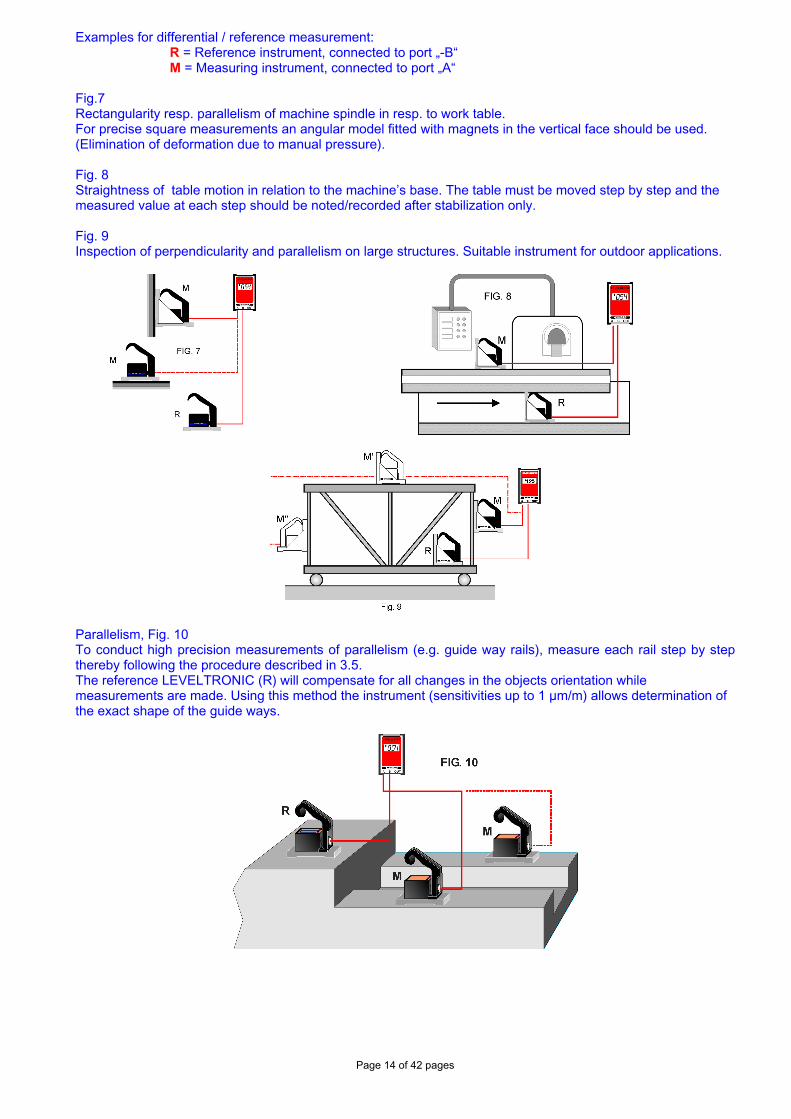
Examples for differential / reference measurement: R = Reference instrument, connected to port „-B“ M = Measuring instrument, connected to port „A“
Fig.7 Rectangularity resp. parallelism of machine spindle in resp. to work table. For precise square measurements an angular model fitted with magnets in the vertical face should be used. (Elimination of deformation due to manual pressure). Fig. 8 Straightness of table motion in relation to the machine’s base. The table must be moved step by step and the measured value at each step should be noted/recorded after stabilization only. Fig. 9 Inspection of perpendicularity and parallelism on large structures. Suitable instrument for outdoor applications.
Parallelism, Fig. 10 To conduct high precision measurements of parallelism (e.g. guide way rails), measure each rail step by step thereby following the procedure described in 3.5. The reference LEVELTRONIC (R) will compensate for all changes in the objects orientation while measurements are made. Using this method the instrument (sensitivities up to 1 µm/m) allows determination of the exact shape of the guide ways.
Page 15 of 42 pages
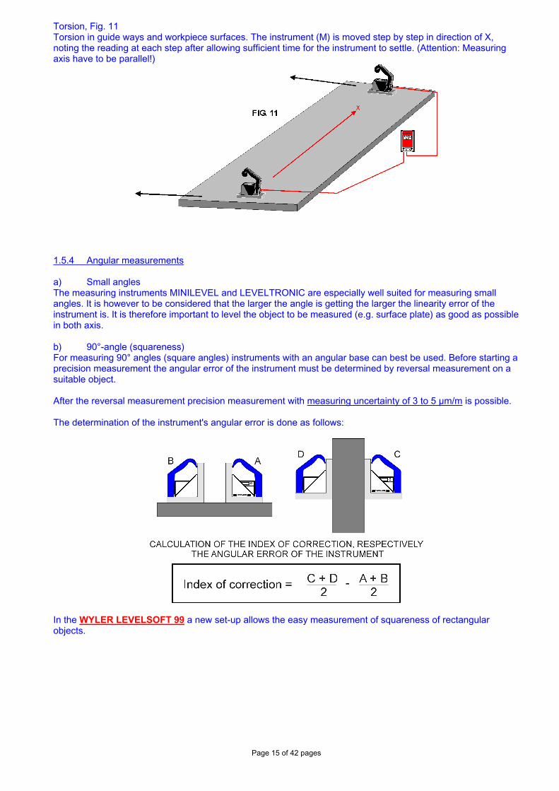
Torsion, Fig. 11 Torsion in guide ways and workpiece surfaces. The instrument (M) is moved step by step in direction of X, noting the reading at each step after allowing sufficient time for the instrument to settle. (Attention: Measuring axis have to be parallel!)
1.5.4 Angular measurements a) Small angles The measuring instruments MINILEVEL and LEVELTRONIC are especially well suited for measuring small angles. It is however to be considered that the larger the angle is getting the larger the linearity error of the instrument is. It is therefore important to level the object to be measured (e.g. surface plate) as good as possible in both axis. b) 90°-angle (squareness) For measuring 90° angles (square angles) instruments with an angular base can best be used. Before starting a precision measurement the angular error of the instrument must be determined by reversal measurement on a suitable object. After the reversal measurement precision measurement with measuring uncertainty of 3 to 5 µm/m is possible. The determination of the instrument's angular error is done as follows:
In the WYLER LEVELSOFT 99 a new set-up allows the easy measurement of squareness of rectangular objects.
Page 16 of 42 pages
Principal procedure of a 90° measurement with WYLER LEVELSOFT The angular error of the instrument must be determined (optional) The measurement follows the required set-up (Step length, number of measurements etc.) After the measurement the respective lines may be adjusted according to different methods. For the following three methods the angular errors are computed and displayed:
• Method Endpoints • Method ISO1101 • Method Linear regression (least square)
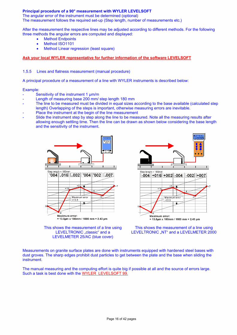
Ask your local WYLER representative for further information of the software LEVELSOFT 1.5.5 Lines and flatness measurement (manual procedure) A principal procedure of a measurement of a line with WYLER instruments is described below: Example: - Sensitivity of the instrument 1 µm/m - Length of measuring base 200 mm/ step length 180 mm - The line to be measured must be divided in equal sizes according to the base available (calculated step
length) Overlapping of the steps is important, otherwise measuring errors are inevitable. - Place the instrument at the begin of the line measurement - Slide the instrument step by step along the line to be measured. Note all the measuring results after
allowing enough settling time. Then the line can be drawn as shown below considering the base length and the sensitivity of the instrument.
This shows the measurement of a line using LEVELTRONIC „classic“ and a
LEVELMETER 25/AC (blue cover)
This shows the measurement of a line using
LEVELTRONIC „NT“ and a LEVELMETER 2000
Measurements on granite surface plates are done with instruments equipped with hardened steel bases with dust groves. The sharp edges prohibit dust particles to get between the plate and the base when sliding the instrument. The manual measuring and the computing effort is quite big if possible at all and the source of errors large. Such a task is best done with the WYLER LEVELSOFT 99.
Page 17 of 42 pages
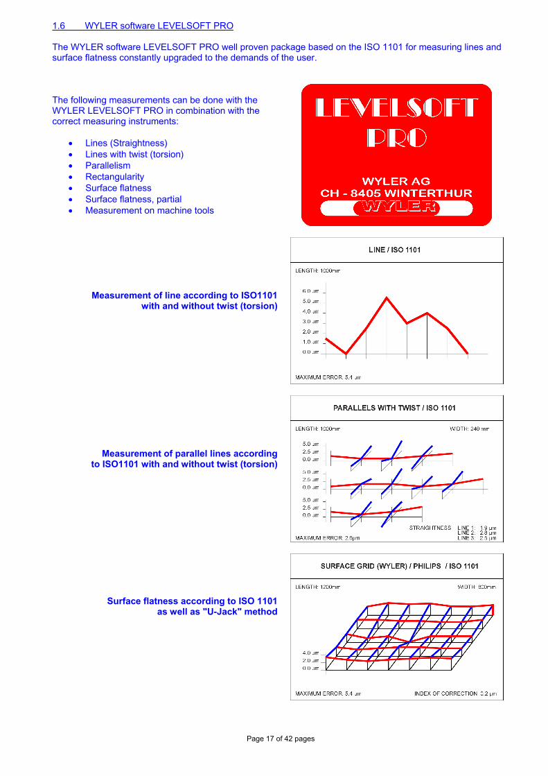
1.6 WYLER software LEVELSOFT PRO The WYLER software LEVELSOFT PRO well proven package based on the ISO 1101 for measuring lines and surface flatness constantly upgraded to the demands of the user. The following measurements can be done with the WYLER LEVELSOFT PRO in combination with the correct measuring instruments:
• Lines (Straightness) • Lines with twist (torsion) • Parallelism • Rectangularity • Surface flatness • Surface flatness, partial • Measurement on machine tools
Measurement of line according to ISO1101with and without twist (torsion)
Measurement of parallel lines according to ISO1101 with and without twist (torsion)
Surface flatness according to ISO 1101as well as "U-Jack" method
Page 18 of 42 pages
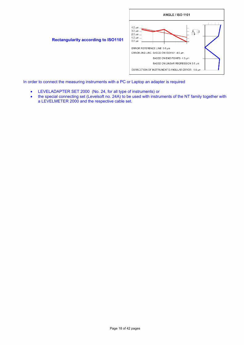
Rectangularity according to ISO1101
In order to connect the measuring instruments with a PC or Laptop an adapter is required
• LEVELADAPTER SET 2000 (No. 24, for all type of instruments) or • the special connecting set (Levelsoft no. 24A) to be used with instruments of the NT family together with
a LEVELMETER 2000 and the respective cable set.
Page 19 of 42 pages
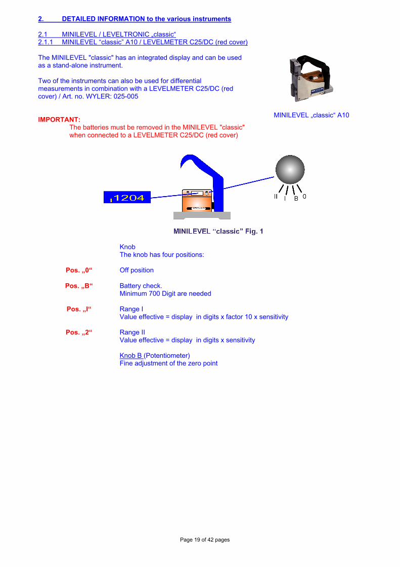
2. DETAILED INFORMATION to the various instruments 2.1 MINILEVEL / LEVELTRONIC „classic“ 2.1.1 MINILEVEL “classic” A10 / LEVELMETER C25/DC (red cover) The MINILEVEL "classic" has an integrated display and can be used as a stand-alone instrument. Two of the instruments can also be used for differential measurements in combination with a LEVELMETER C25/DC (red cover) / Art. no. WYLER: 025-005 IMPORTANT:
The batteries must be removed in the MINILEVEL "classic" when connected to a LEVELMETER C25/DC (red cover)
MINILEVEL „classic“ A10
Knob
The knob has four positions:
Pos. „0“ Off position
Pos. „B“ Battery check. Minimum 700 Digit are needed
Pos. „I“ Range I Value effective = display in digits x factor 10 x sensitivity
Pos. „2“ Range II Value effective = display in digits x sensitivity
Knob B (Potentiometer) Fine adjustment of the zero point
Page 20 of 42 pages
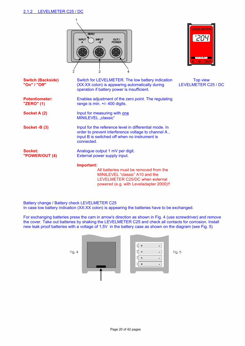
2.1.2 LEVELMETER C25 / DC
Switch (Backside) "On" / "Off"
Switch for LEVELMETER. The low battery indication (XX:XX colon) is appearing automatically during operation if battery power is insufficient.
Top view LEVELMETER C25 / DC
Potentiometer: "ZERO" (1)
Enables adjustment of the zero point. The regulating range is min. +/- 400 digits.
Socket A (2) Input for measuring with one MINILEVEL „classic“
Socket -B (3) Input for the reference level in differential mode. In order to prevent interference voltage to channel A , input B is switched off when no instrument is connected.
Socket: "POWER/OUT (4)
Analogue output 1 mV per digit. External power supply input. Important:
All batteries must be removed from the MINILEVEL “classic” A10 and the LEVELMETER C25/DC when external powered (e.g. with Leveladapter 2000)!!
Battery change / Battery check LEVELMETER C25 In case low battery indication (XX:XX colon) is appearing the batteries have to be exchanged. For exchanging batteries press the cam in arrow's direction as shown in Fig. 4 (use screwdriver) and remove the cover. Take out batteries by shaking the LEVELMETER C25 and check all contacts for corrosion. Install new leak proof batteries with a voltage of 1,5V in the battery case as shown on the diagram (see Fig. 5)
Page 21 of 42 pages
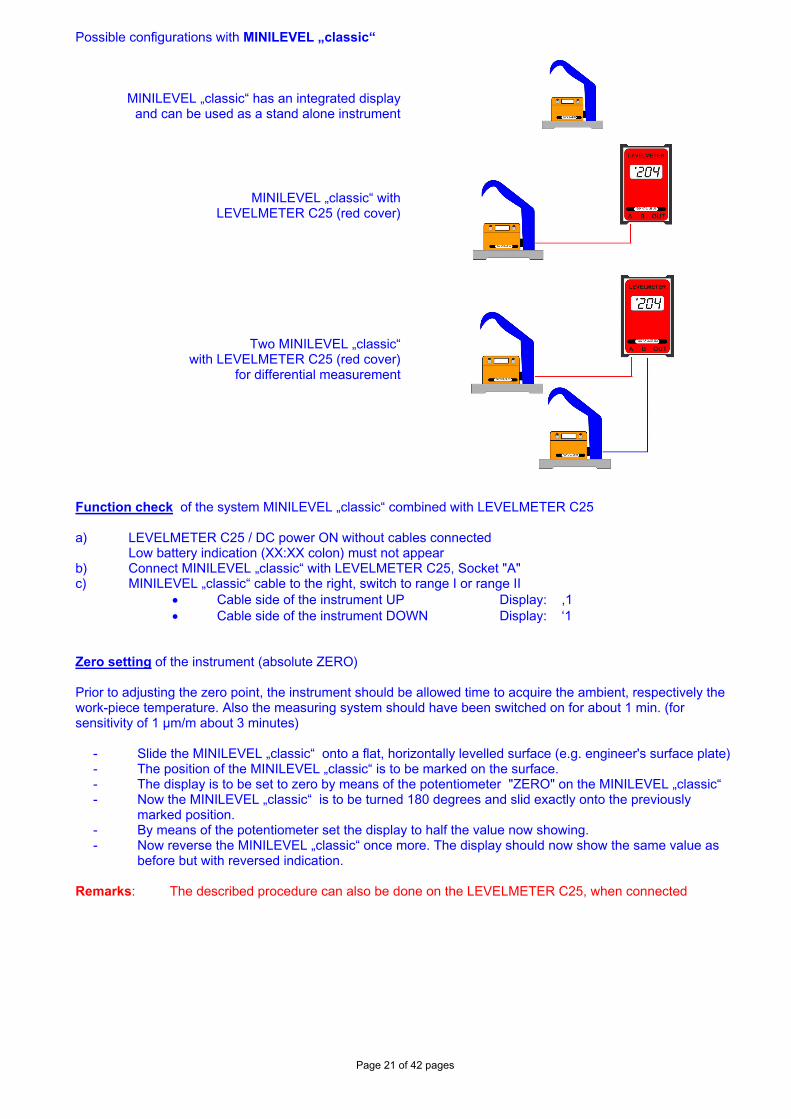
Possible configurations with MINILEVEL „classic“
MINILEVEL „classic“ has an integrated display and can be used as a stand alone instrument
MINILEVEL „classic“ with LEVELMETER C25 (red cover)
Two MINILEVEL „classic“ with LEVELMETER C25 (red cover)
for differential measurement
Function check of the system MINILEVEL „classic“ combined with LEVELMETER C25 a) LEVELMETER C25 / DC power ON without cables connected Low battery indication (XX:XX colon) must not appear b) Connect MINILEVEL „classic“ with LEVELMETER C25, Socket "A" c) MINILEVEL „classic“ cable to the right, switch to range I or range II
• Cable side of the instrument UP Display: ,1 • Cable side of the instrument DOWN Display: ‘1
Zero setting of the instrument (absolute ZERO) Prior to adjusting the zero point, the instrument should be allowed time to acquire the ambient, respectively the work-piece temperature. Also the measuring system should have been switched on for about 1 min. (for sensitivity of 1 µm/m about 3 minutes)
- Slide the MINILEVEL „classic“ onto a flat, horizontally levelled surface (e.g. engineer's surface plate) - The position of the MINILEVEL „classic“ is to be marked on the surface. - The display is to be set to zero by means of the potentiometer "ZERO" on the MINILEVEL „classic“ - Now the MINILEVEL „classic“ is to be turned 180 degrees and slid exactly onto the previously
marked position. - By means of the potentiometer set the display to half the value now showing. - Now reverse the MINILEVEL „classic“ once more. The display should now show the same value as
before but with reversed indication. Remarks: The described procedure can also be done on the LEVELMETER C25, when connected
Page 22 of 42 pages
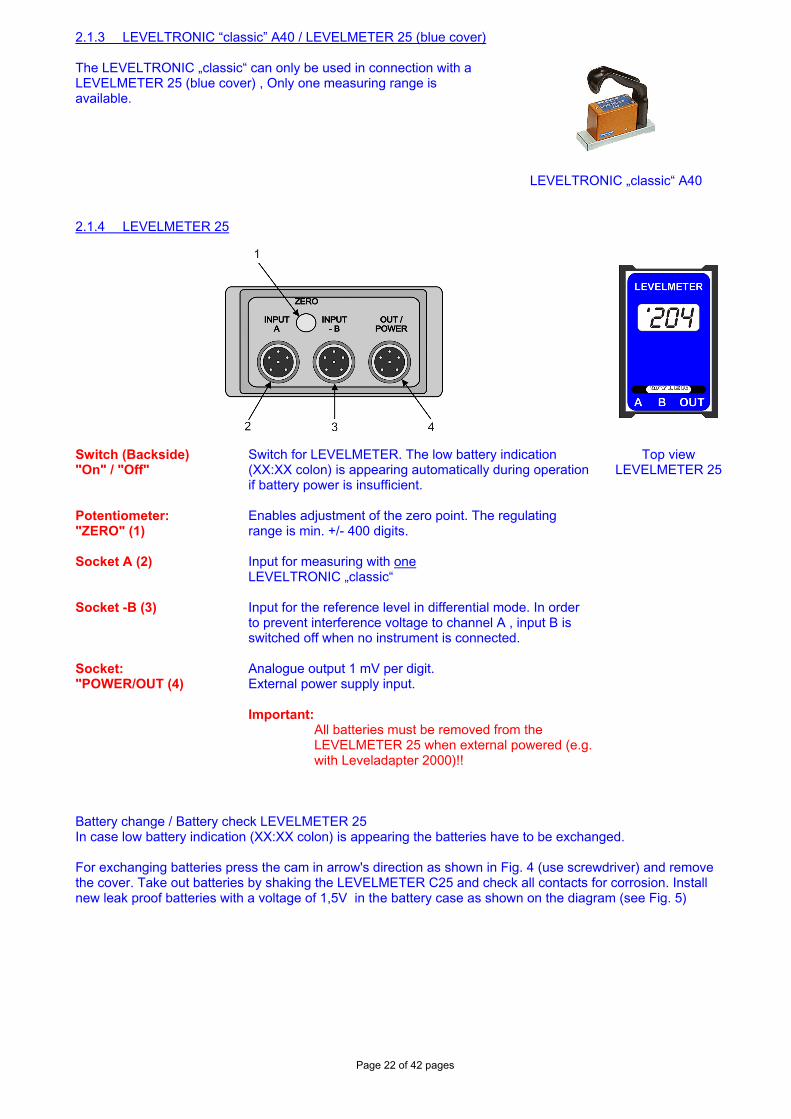
2.1.3 LEVELTRONIC “classic” A40 / LEVELMETER 25 (blue cover) The LEVELTRONIC „classic“ can only be used in connection with a LEVELMETER 25 (blue cover) , Only one measuring range is available.
LEVELTRONIC „classic“ A40 2.1.4 LEVELMETER 25
Switch (Backside) "On" / "Off"
Switch for LEVELMETER. The low battery indication (XX:XX colon) is appearing automatically during operation if battery power is insufficient.
Top view LEVELMETER 25
Potentiometer: "ZERO" (1)
Enables adjustment of the zero point. The regulating range is min. +/- 400 digits.
Socket A (2) Input for measuring with one LEVELTRONIC „classic“
Socket -B (3) Input for the reference level in differential mode. In order to prevent interference voltage to channel A , input B is switched off when no instrument is connected.
Socket: "POWER/OUT (4)
Analogue output 1 mV per digit. External power supply input. Important:
All batteries must be removed from the LEVELMETER 25 when external powered (e.g. with Leveladapter 2000)!!
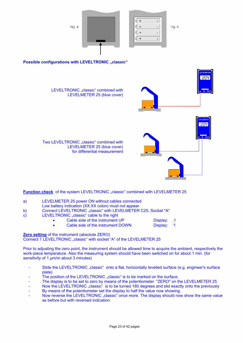
Battery change / Battery check LEVELMETER 25 In case low battery indication (XX:XX colon) is appearing the batteries have to be exchanged. For exchanging batteries press the cam in arrow's direction as shown in Fig. 4 (use screwdriver) and remove the cover. Take out batteries by shaking the LEVELMETER C25 and check all contacts for corrosion. Install new leak proof batteries with a voltage of 1,5V in the battery case as shown on the diagram (see Fig. 5)
Page 23 of 42 pages
Possible configurations with LEVELTRONIC „classic“
LEVELTRONIC „classic“ combined with LEVELMETER 25 (blue cover)
Two LEVELTRONIC „classic“ combined with LEVELMETER 25 (blue cover)
for differential measurement
Function check of the system LEVELTRONIC „classic“ combined with LEVELMETER 25 a) LEVELMETER 25 power ON without cables connected Low battery indication (XX:XX colon) must not appear b) Connect LEVELTRONIC „classic“ with LEVELMETER C25, Socket "A" c) LEVELTRONIC „classic“ cable to the right
• Cable side of the instrument UP Display: ,1 • Cable side of the instrument DOWN Display: ‘1
Zero setting of the instrument (absolute ZERO) Connect 1 LEVELTRONIC „classic“ with socket “A” of the LEVELMETER 25 Prior to adjusting the zero point, the instrument should be allowed time to acquire the ambient, respectively the work-piece temperature. Also the measuring system should have been switched on for about 1 min. (for sensitivity of 1 µm/m about 3 minutes)
- Slide the LEVELTRONIC „classic“ onto a flat, horizontally levelled surface (e.g. engineer's surface plate)
- The position of the LEVELTRONIC „classic“ is to be marked on the surface. - The display is to be set to zero by means of the potentiometer "ZERO" on the LEVELMETER 25 - Now the LEVELTRONIC „classic“ is to be turned 180 degrees and slid exactly onto the previously - By means of the potentiometer set the display to half the value now showing. - Now reverse the LEVELTRONIC „classic“ once more. The display should now show the same value
as before but with reversed indication.
Page 24 of 42 pages
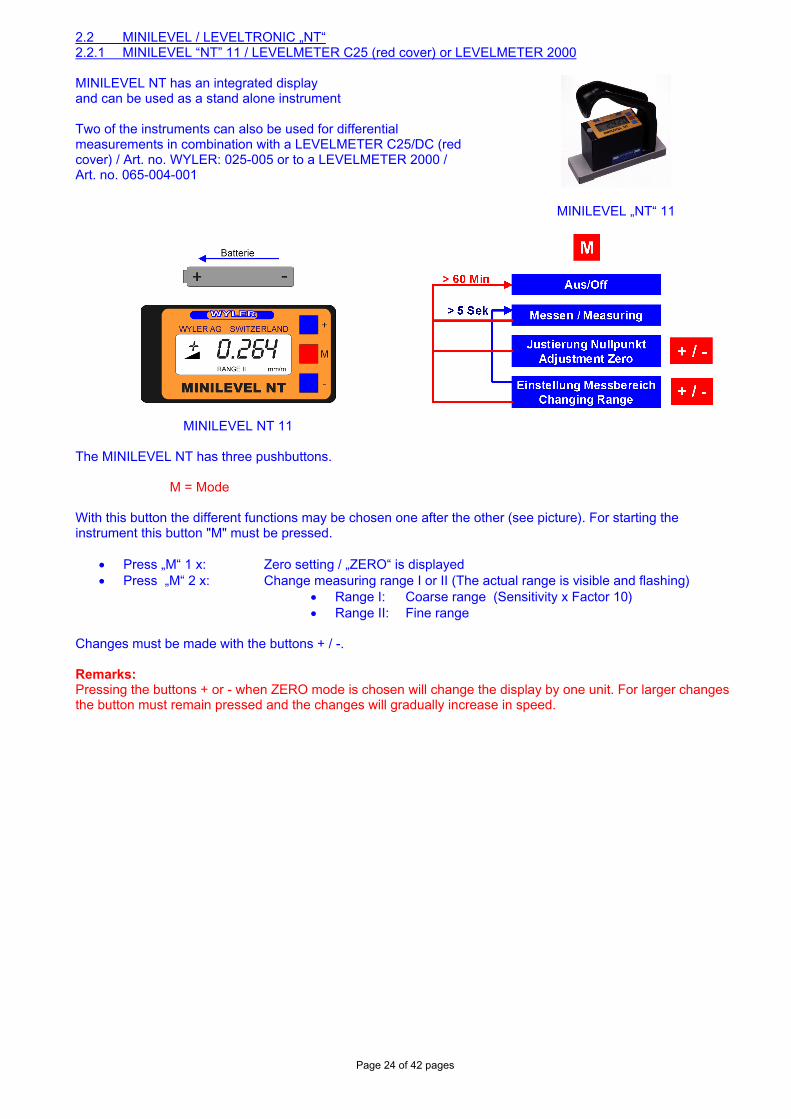
2.2 MINILEVEL / LEVELTRONIC „NT“ 2.2.1 MINILEVEL “NT” 11 / LEVELMETER C25 (red cover) or LEVELMETER 2000 MINILEVEL NT has an integrated display and can be used as a stand alone instrument Two of the instruments can also be used for differential measurements in combination with a LEVELMETER C25/DC (red cover) / Art. no. WYLER: 025-005 or to a LEVELMETER 2000 / Art. no. 065-004-001
MINILEVEL „NT“ 11
MINILEVEL NT 11
The MINILEVEL NT has three pushbuttons.
M = Mode With this button the different functions may be chosen one after the other (see picture). For starting the instrument this button "M" must be pressed.
• Press „M“ 1 x: Zero setting / „ZERO“ is displayed • Press „M“ 2 x: Change measuring range I or II (The actual range is visible and flashing)
• Range I: Coarse range (Sensitivity x Factor 10) • Range II: Fine range
Changes must be made with the buttons + / -. Remarks: Pressing the buttons + or - when ZERO mode is chosen will change the display by one unit. For larger changes the button must remain pressed and the changes will gradually increase in speed.
Page 25 of 42 pages
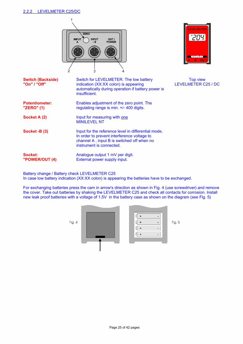
2.2.2 LEVELMETER C25/DC
Switch (Backside) "On" / "Off"
Switch for LEVELMETER. The low battery indication (XX:XX colon) is appearing automatically during operation if battery power is insufficient.
Top view LEVELMETER C25 / DC
Potentiometer: "ZERO" (1)
Enables adjustment of the zero point. The regulating range is min. +/- 400 digits.
Socket A (2) Input for measuring with one MINILEVEL NT
Socket -B (3) Input for the reference level in differential mode. In order to prevent interference voltage to channel A , input B is switched off when no instrument is connected.
Socket: "POWER/OUT (4)
Analogue output 1 mV per digit. External power supply input.
Battery change / Battery check LEVELMETER C25 In case low battery indication (XX:XX colon) is appearing the batteries have to be exchanged. For exchanging batteries press the cam in arrow's direction as shown in Fig. 4 (use screwdriver) and remove the cover. Take out batteries by shaking the LEVELMETER C25 and check all contacts for corrosion. Install new leak proof batteries with a voltage of 1,5V in the battery case as shown on the diagram (see Fig. 5)
Page 26 of 42 pages
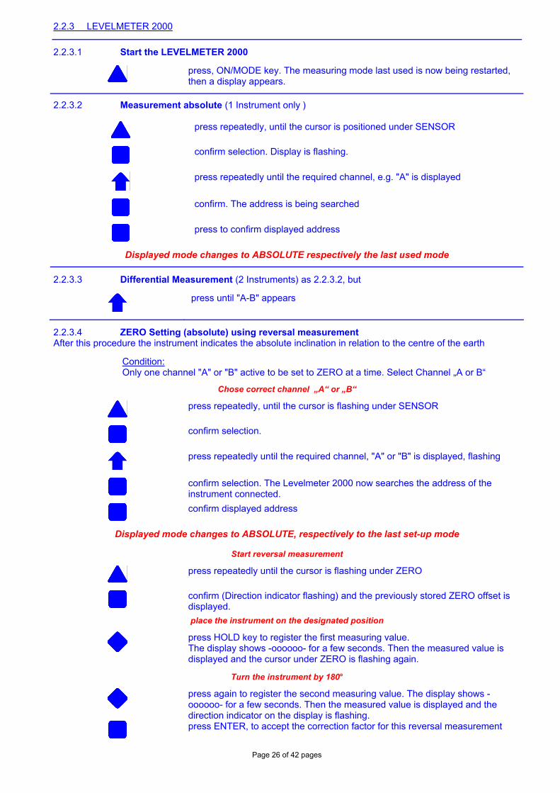
2.2.3 LEVELMETER 2000
2.2.3.1 Start the LEVELMETER 2000
press, ON/MODE key. The measuring mode last used is now being restarted, then a display appears.
2.2.3.2 Measurement absolute (1 Instrument only )
press repeatedly, until the cursor is positioned under SENSOR
confirm selection. Display is flashing.
press repeatedly until the required channel, e.g. "A" is displayed
confirm. The address is being searched
press to confirm displayed address
Displayed mode changes to ABSOLUTE respectively the last used mode
2.2.3.3 Differential Measurement (2 Instruments) as 2.2.3.2, but
press until "A-B" appears
2.2.3.4 ZERO Setting (absolute) using reversal measurement After this procedure the instrument indicates the absolute inclination in relation to the centre of the earth
Condition: Only one channel "A" or "B" active to be set to ZERO at a time. Select Channel „A or B“
Chose correct channel „A“ or „B“
press repeatedly, until the cursor is flashing under SENSOR
confirm selection.
press repeatedly until the required channel, "A" or "B" is displayed, flashing
confirm selection. The Levelmeter 2000 now searches the address of the instrument connected.
confirm displayed address
Displayed mode changes to ABSOLUTE, respectively to the last set-up mode
Start reversal measurement
press repeatedly until the cursor is flashing under ZERO
confirm (Direction indicator flashing) and the previously stored ZERO offset is displayed.
place the instrument on the designated position
press HOLD key to register the first measuring value. The display shows -oooooo- for a few seconds. Then the measured value is displayed and the cursor under ZERO is flashing again.
Turn the instrument by 180°
press again to register the second measuring value. The display shows -oooooo- for a few seconds. Then the measured value is displayed and the direction indicator on the display is flashing.
press ENTER, to accept the correction factor for this reversal measurement
Page 27 of 42 pages
Displayed mode changes to ABSOLUTE
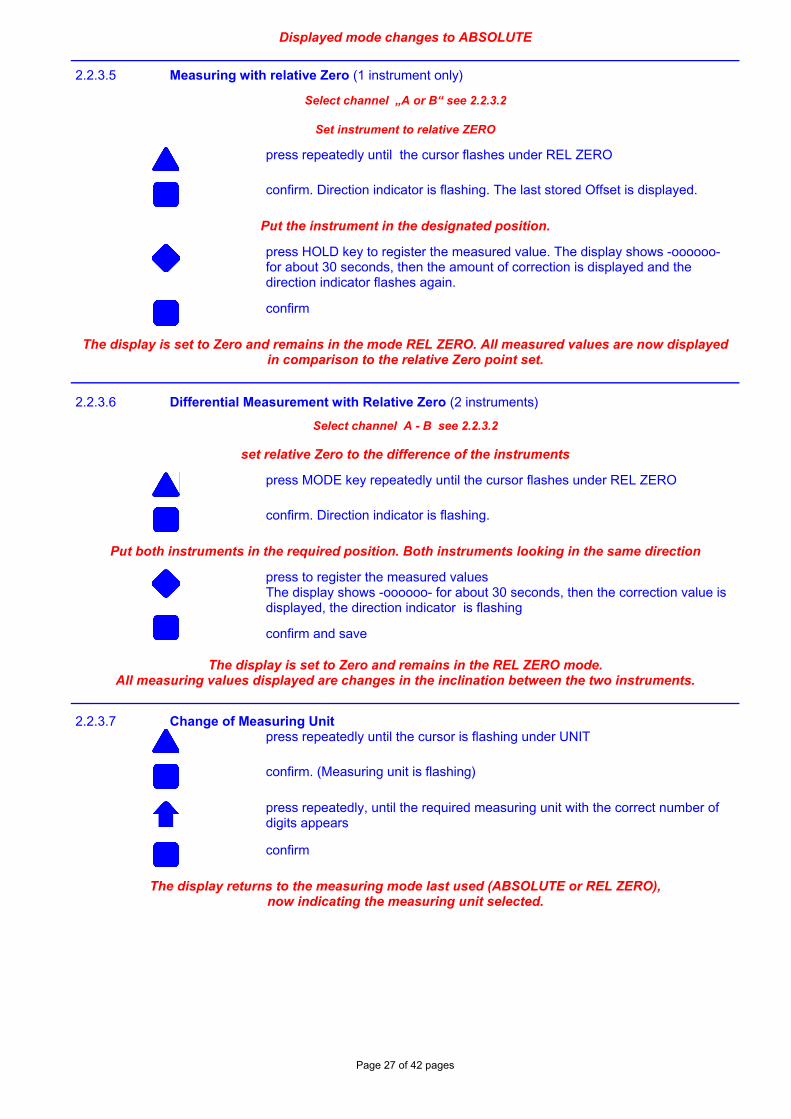
2.2.3.5 Measuring with relative Zero (1 instrument only)
Select channel „A or B“ see 2.2.3.2
Set instrument to relative ZERO
press repeatedly until the cursor flashes under REL ZERO
confirm. Direction indicator is flashing. The last stored Offset is displayed.
Put the instrument in the designated position.
press HOLD key to register the measured value. The display shows -oooooo- for about 30 seconds, then the amount of correction is displayed and the direction indicator flashes again.
confirm
The display is set to Zero and remains in the mode REL ZERO. All measured values are now displayed in comparison to the relative Zero point set.
2.2.3.6 Differential Measurement with Relative Zero (2 instruments)
Select channel A - B see 2.2.3.2
set relative Zero to the difference of the instruments
press MODE key repeatedly until the cursor flashes under REL ZERO
confirm. Direction indicator is flashing.
Put both instruments in the required position. Both instruments looking in the same direction
press to register the measured values The display shows -oooooo- for about 30 seconds, then the correction value is displayed, the direction indicator is flashing
confirm and save
The display is set to Zero and remains in the REL ZERO mode. All measuring values displayed are changes in the inclination between the two instruments.
2.2.3.7 Change of Measuring Unit
press repeatedly until the cursor is flashing under UNIT
confirm. (Measuring unit is flashing)
press repeatedly, until the required measuring unit with the correct number of digits appears
confirm
The display returns to the measuring mode last used (ABSOLUTE or REL ZERO), now indicating the measuring unit selected.
Page 28 of 42 pages
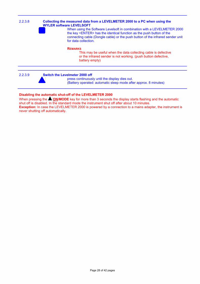
2.2.3.8 Collecting the measured data from a LEVELMETER 2000 to a PC when using the WYLER software LEVELSOFT
When using the Software Levelsoft in combination with a LEVELMETER 2000 the key <ENTER> has the identical function as the push button of the connecting cable (Dongle cable) or the push button of the infrared sender unit for data collection. REMARKS This may be useful when the data collecting cable is defective or the infrared sender is not working. (push button defective, battery empty)
2.2.3.9 Switch the Levelmeter 2000 off
press continuously until the display dies out. (Battery operated: automatic sleep mode after approx. 8 minutes)
Disabling the automatic shut-off of the LEVELMETER 2000 When pressing the ON/MODE key for more than 3 seconds the display starts flashing and the automatic shut off is disabled. In the standard mode the instrument shut off after about 10 minutes. Exception: In case the LEVELMETER 2000 is powered by a connection to a mains adapter, the instrument is never shutting off automatically.
Page 29 of 42 pages
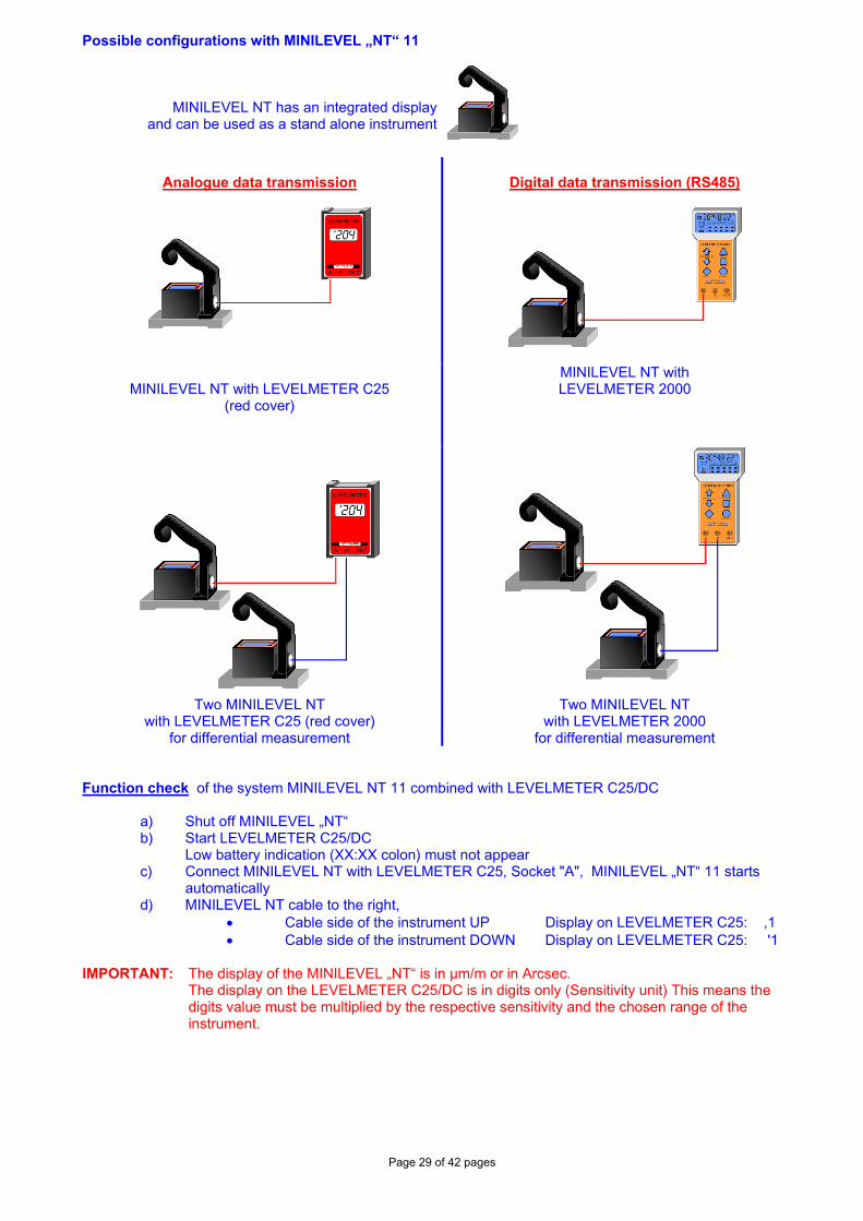
Possible configurations with MINILEVEL „NT“ 11
MINILEVEL NT has an integrated display and can be used as a stand alone instrument
Analogue data transmission
Digital data transmission (RS485)
MINILEVEL NT with LEVELMETER C25
(red cover)
MINILEVEL NT with LEVELMETER 2000
Two MINILEVEL NT
with LEVELMETER C25 (red cover) for differential measurement
Two MINILEVEL NT with LEVELMETER 2000
for differential measurement Function check of the system MINILEVEL NT 11 combined with LEVELMETER C25/DC
a) Shut off MINILEVEL „NT“ b) Start LEVELMETER C25/DC Low battery indication (XX:XX colon) must not appear c) Connect MINILEVEL NT with LEVELMETER C25, Socket "A", MINILEVEL „NT“ 11 starts
automatically d) MINILEVEL NT cable to the right,
• Cable side of the instrument UP Display on LEVELMETER C25: ,1 • Cable side of the instrument DOWN Display on LEVELMETER C25: '1
IMPORTANT: The display of the MINILEVEL „NT“ is in µm/m or in Arcsec.
The display on the LEVELMETER C25/DC is in digits only (Sensitivity unit) This means the digits value must be multiplied by the respective sensitivity and the chosen range of the instrument.
Page 30 of 42 pages
Zero setting of the measuring system MINILEVEL „NT“ 11 with LEVELMETER C25/DC Prior to adjusting the zero point, the instrument should be allowed time to acquire the ambient, respectively the work-piece temperature. Also the measuring system should have been switched on for about 1 min. (for sensitivity of 1 µm/m about 3 minutes) The absolute zero setting can be done in two ways. a) with the MINILEVEL NT
- Slide the MINILEVEL NT onto a flat, horizontally levelled surface (e.g. engineer's surface plate) - The position of the MINILEVEL NT is to be marked on the surface. - Press the pushbutton "M" once until the ZERO is flashing, use the + or - keys to bring the
display to "0" - Now the MINILEVEL NT is to be turned 180 degrees and slid exactly onto the previously marked
position. - By means of the + / - keys set the display to half the value now showing. - Now reverse the MINILEVEL NT once more. The display should now show the same value as before
but with reversed indication. - The display on the LEVELMETER C25/DC must be adjusted with the potentiometer ZERO to indicate
the same value as on the MINILEVEL NT b) using the LEVELMETER C25/DC
- Slide the MINILEVEL „NT“ onto a flat, horizontally levelled surface (e.g. engineer's surface plate) - The position of the MINILEVEL „NT“ is to be marked on the surface. - The display is to be set to zero by means of the potentiometer "ZERO" on the LEVELMETER C25 - Now the MINILEVEL „NT“ is to be turned 180 degrees and slid exactly onto the previously - By means of the potentiometer set the display on the LEVELMETER C25 to half the value now
showing. - Now reverse the MINILEVEL „NT“ once more. The display should now show the same value as
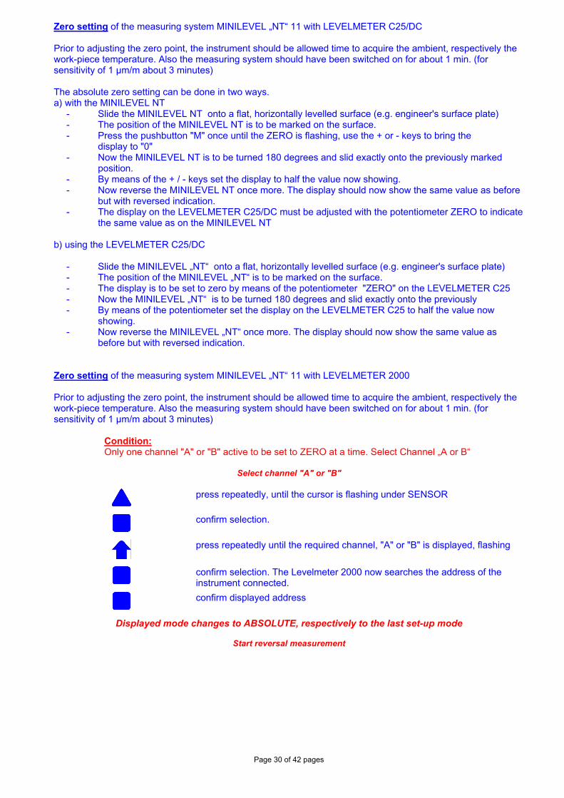
before but with reversed indication. Zero setting of the measuring system MINILEVEL „NT“ 11 with LEVELMETER 2000 Prior to adjusting the zero point, the instrument should be allowed time to acquire the ambient, respectively the work-piece temperature. Also the measuring system should have been switched on for about 1 min. (for sensitivity of 1 µm/m about 3 minutes)
Condition: Only one channel "A" or "B" active to be set to ZERO at a time. Select Channel „A or B“
Select channel "A" or "B"
press repeatedly, until the cursor is flashing under SENSOR
confirm selection.
press repeatedly until the required channel, "A" or "B" is displayed, flashing
confirm selection. The Levelmeter 2000 now searches the address of the instrument connected.
confirm displayed address
Displayed mode changes to ABSOLUTE, respectively to the last set-up mode
Start reversal measurement
Page 31 of 42 pages
press repeatedly until the cursor is flashing under ZERO
confirm (Direction indicator flashing) and the previously stored ZERO offset is displayed.
place the instrument on the designated position
press HOLD key to register the first measuring value. The display shows -oooooo- for a few seconds. Then the measured value is displayed and the cursor under ZERO is flashing again.
Turn the instrument by 180°
press again to register the second measuring value. The display shows -oooooo- for a few seconds. Then the measured value is displayed and the direction indicator on the display is flashing.
press ENTER, to accept the correction factor for this reversal measurement
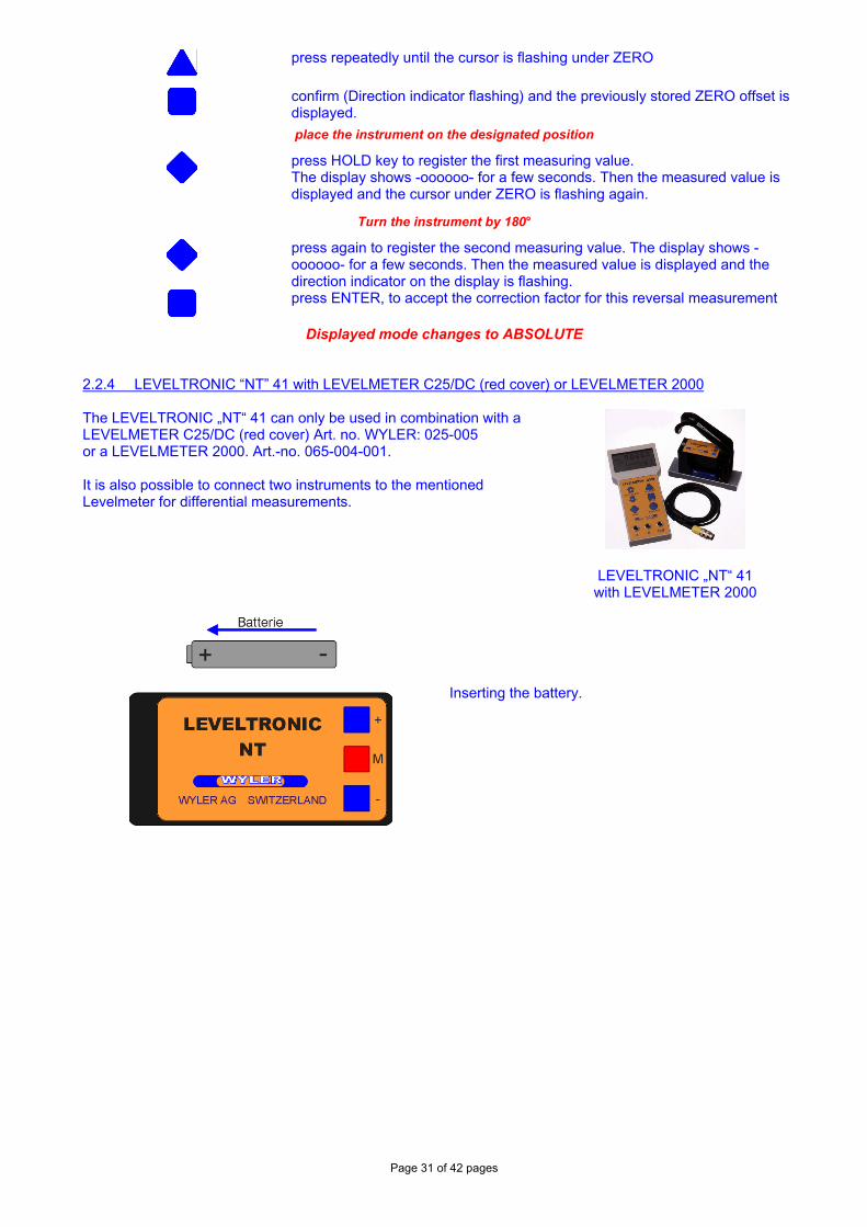
Displayed mode changes to ABSOLUTE 2.2.4 LEVELTRONIC “NT” 41 with LEVELMETER C25/DC (red cover) or LEVELMETER 2000 The LEVELTRONIC „NT“ 41 can only be used in combination with a LEVELMETER C25/DC (red cover) Art. no. WYLER: 025-005 or a LEVELMETER 2000. Art.-no. 065-004-001. It is also possible to connect two instruments to the mentioned Levelmeter for differential measurements.
LEVELTRONIC „NT“ 41 with LEVELMETER 2000
Inserting the battery.
Page 32 of 42 pages
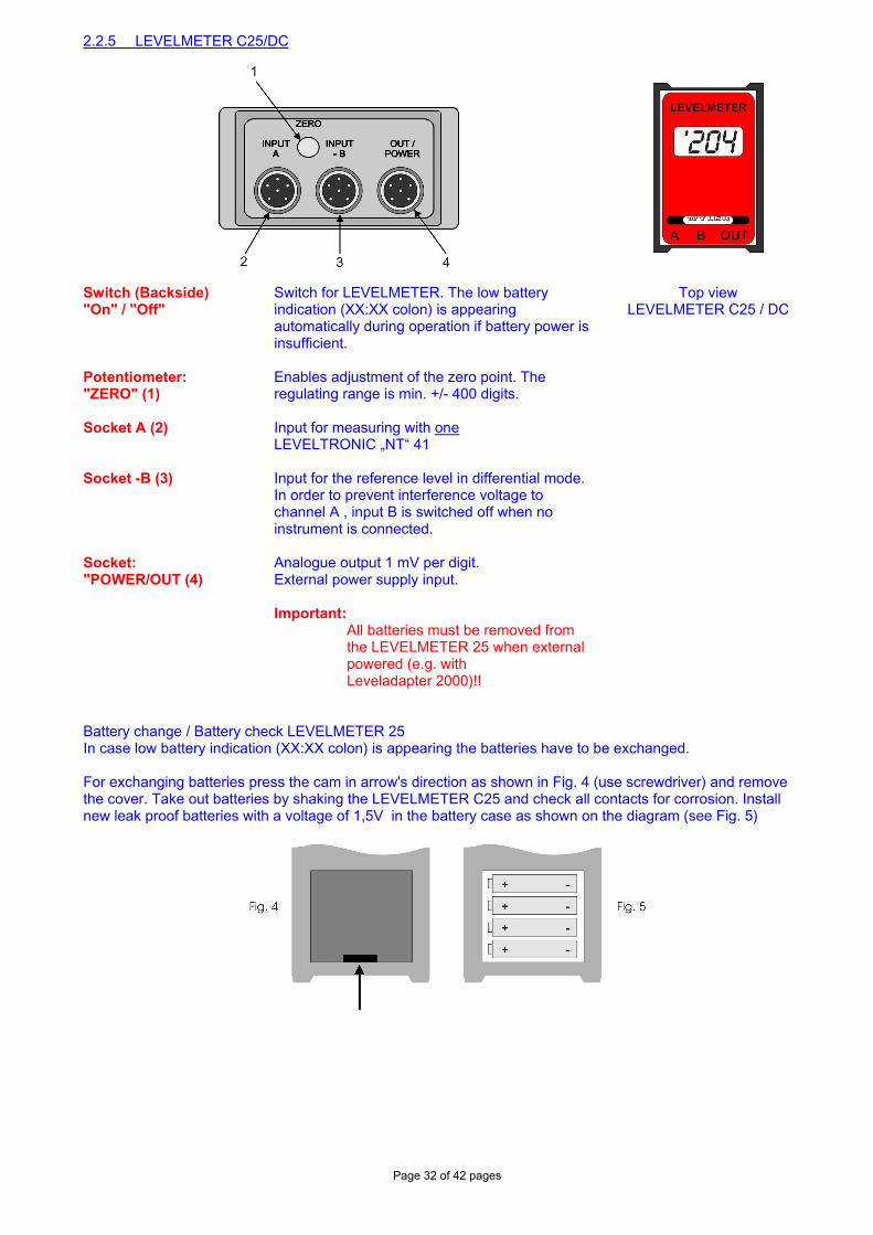
2.2.5 LEVELMETER C25/DC
Switch (Backside) "On" / "Off"
Switch for LEVELMETER. The low battery indication (XX:XX colon) is appearing automatically during operation if battery power is insufficient.
Top view LEVELMETER C25 / DC
Potentiometer: "ZERO" (1)
Enables adjustment of the zero point. The regulating range is min. +/- 400 digits.
Socket A (2) Input for measuring with one LEVELTRONIC „NT“ 41
Socket -B (3) Input for the reference level in differential mode. In order to prevent interference voltage to channel A , input B is switched off when no instrument is connected.
Socket: "POWER/OUT (4)
Analogue output 1 mV per digit. External power supply input. Important:
All batteries must be removed from the LEVELMETER 25 when external powered (e.g. with Leveladapter 2000)!!
Battery change / Battery check LEVELMETER 25 In case low battery indication (XX:XX colon) is appearing the batteries have to be exchanged. For exchanging batteries press the cam in arrow's direction as shown in Fig. 4 (use screwdriver) and remove the cover. Take out batteries by shaking the LEVELMETER C25 and check all contacts for corrosion. Install new leak proof batteries with a voltage of 1,5V in the battery case as shown on the diagram (see Fig. 5)
Page 33 of 42 pages
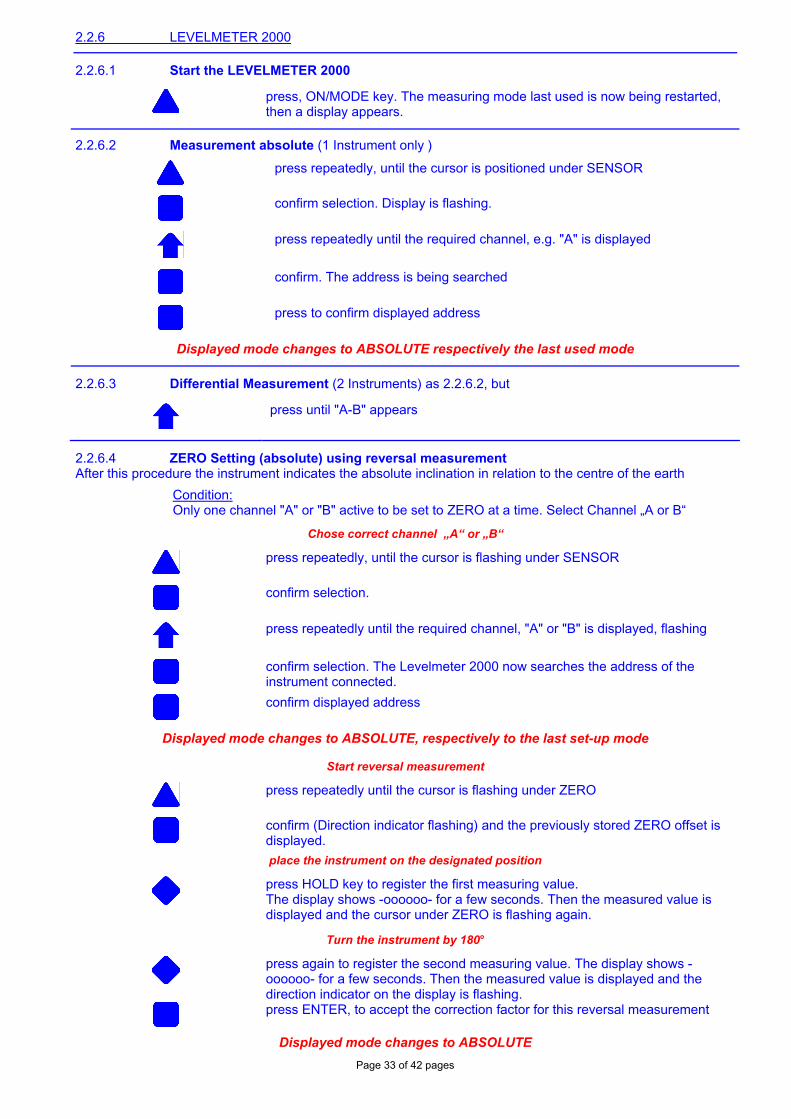
2.2.6 LEVELMETER 2000
2.2.6.1 Start the LEVELMETER 2000
press, ON/MODE key. The measuring mode last used is now being restarted, then a display appears.
2.2.6.2 Measurement absolute (1 Instrument only )
press repeatedly, until the cursor is positioned under SENSOR
confirm selection. Display is flashing.
press repeatedly until the required channel, e.g. "A" is displayed
confirm. The address is being searched
press to confirm displayed address
Displayed mode changes to ABSOLUTE respectively the last used mode
2.2.6.3 Differential Measurement (2 Instruments) as 2.2.6.2, but
press until "A-B" appears
2.2.6.4 ZERO Setting (absolute) using reversal measurement After this procedure the instrument indicates the absolute inclination in relation to the centre of the earth
Condition: Only one channel "A" or "B" active to be set to ZERO at a time. Select Channel „A or B“
Chose correct channel „A“ or „B“
press repeatedly, until the cursor is flashing under SENSOR
confirm selection.
press repeatedly until the required channel, "A" or "B" is displayed, flashing
confirm selection. The Levelmeter 2000 now searches the address of the instrument connected.
confirm displayed address
Displayed mode changes to ABSOLUTE, respectively to the last set-up mode
Start reversal measurement
press repeatedly until the cursor is flashing under ZERO
confirm (Direction indicator flashing) and the previously stored ZERO offset is displayed.
place the instrument on the designated position
press HOLD key to register the first measuring value. The display shows -oooooo- for a few seconds. Then the measured value is displayed and the cursor under ZERO is flashing again.
Turn the instrument by 180°
press again to register the second measuring value. The display shows -oooooo- for a few seconds. Then the measured value is displayed and the direction indicator on the display is flashing.
press ENTER, to accept the correction factor for this reversal measurement
Displayed mode changes to ABSOLUTE
Page 34 of 42 pages
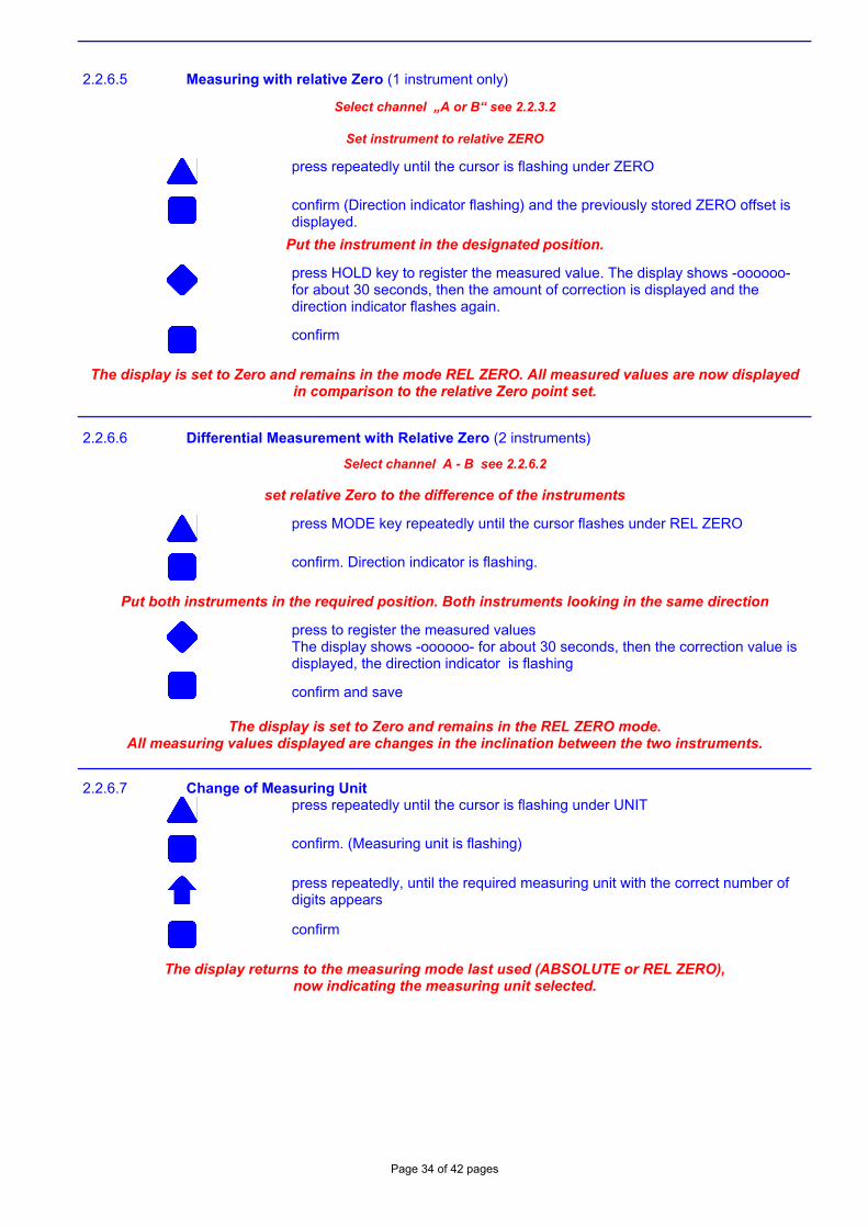
2.2.6.5 Measuring with relative Zero (1 instrument only)
Select channel „A or B“ see 2.2.3.2
Set instrument to relative ZERO
press repeatedly until the cursor is flashing under ZERO
confirm (Direction indicator flashing) and the previously stored ZERO offset is displayed.
Put the instrument in the designated position.
press HOLD key to register the measured value. The display shows -oooooo- for about 30 seconds, then the amount of correction is displayed and the direction indicator flashes again.
confirm
The display is set to Zero and remains in the mode REL ZERO. All measured values are now displayed in comparison to the relative Zero point set.
2.2.6.6 Differential Measurement with Relative Zero (2 instruments)
Select channel A - B see 2.2.6.2
set relative Zero to the difference of the instruments
press MODE key repeatedly until the cursor flashes under REL ZERO
confirm. Direction indicator is flashing.
Put both instruments in the required position. Both instruments looking in the same direction
press to register the measured values The display shows -oooooo- for about 30 seconds, then the correction value is displayed, the direction indicator is flashing
confirm and save
The display is set to Zero and remains in the REL ZERO mode. All measuring values displayed are changes in the inclination between the two instruments.
2.2.6.7 Change of Measuring Unit
press repeatedly until the cursor is flashing under UNIT
confirm. (Measuring unit is flashing)
press repeatedly, until the required measuring unit with the correct number of digits appears
confirm
The display returns to the measuring mode last used (ABSOLUTE or REL ZERO), now indicating the measuring unit selected.
Page 35 of 42 pages
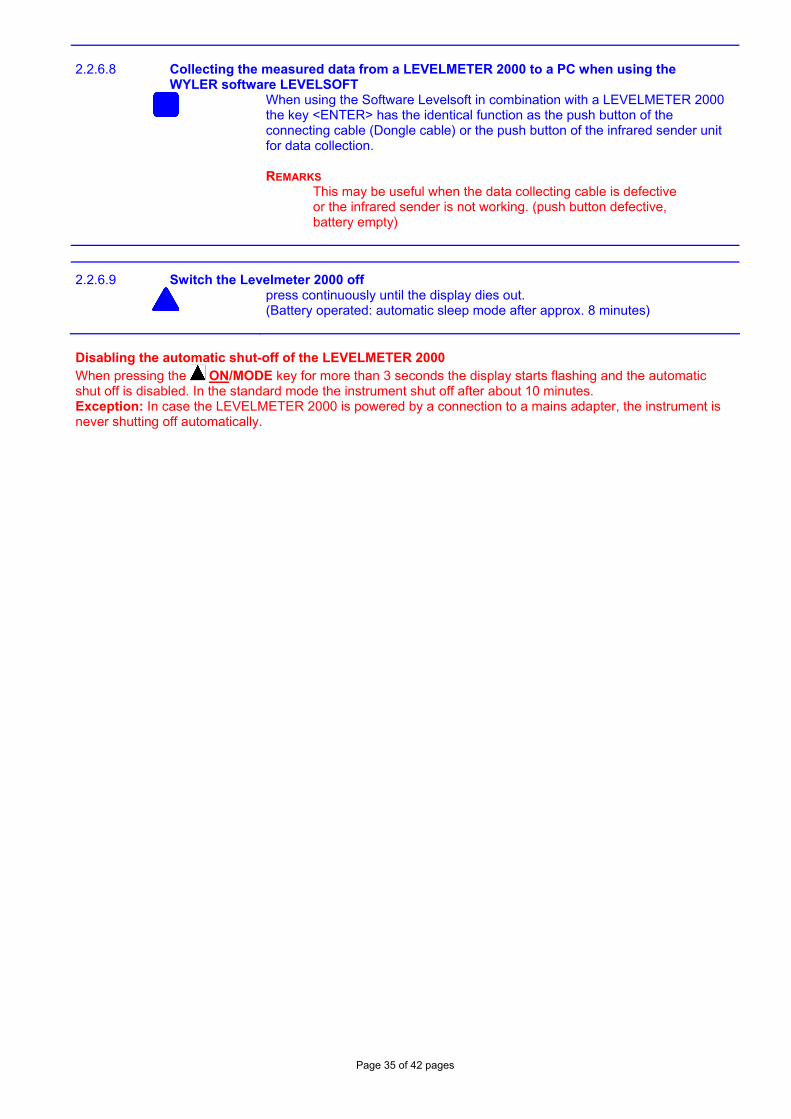
2.2.6.8 Collecting the measured data from a LEVELMETER 2000 to a PC when using the WYLER software LEVELSOFT
When using the Software Levelsoft in combination with a LEVELMETER 2000 the key <ENTER> has the identical function as the push button of the connecting cable (Dongle cable) or the push button of the infrared sender unit for data collection. REMARKS This may be useful when the data collecting cable is defective or the infrared sender is not working. (push button defective, battery empty)
2.2.6.9 Switch the Levelmeter 2000 off
press continuously until the display dies out. (Battery operated: automatic sleep mode after approx. 8 minutes)
Disabling the automatic shut-off of the LEVELMETER 2000 When pressing the ON/MODE key for more than 3 seconds the display starts flashing and the automatic shut off is disabled. In the standard mode the instrument shut off after about 10 minutes. Exception: In case the LEVELMETER 2000 is powered by a connection to a mains adapter, the instrument is never shutting off automatically.
Page 36 of 42 pages
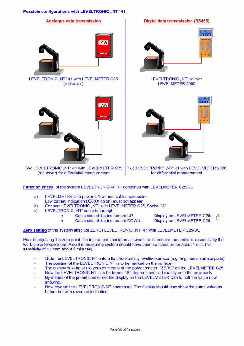
Possible configurations with LEVELTRONIC „NT“ 41
Analogue data transmission
Digital data transmission (RS485)
LEVELTRONIC „NT“ 41 with LEVELMETER C25 (red cover)
LEVELTRONIC „NT“ 41 with LEVELMETER 2000
Two LEVELTRONIC „NT“ 41 with LEVELMETER C25
(red cover) for differential measurement Two LEVELTRONIC „NT“ 41 with LEVELMETER 2000
for differential measurement Function check of the system LEVELTRONIC NT 11 combined with LEVELMETER C25/DC
a) LEVELMETER C25 power ON without cables connected Low battery indication (XX:XX colon) must not appear b) Connect LEVELTRONIC „NT“ with LEVELMETER C25, Socket "A" c) LEVELTRONIC „NT“ cable to the right,
• Cable side of the instrument UP Display on LEVELMETER C25: ,1 • Cable side of the instrument DOWN Display on LEVELMETER C25: ‘1
Zero setting of the system(absolute ZERO) LEVELTRONIC „NT“ 41 with LEVELMETER C25/DC Prior to adjusting the zero point, the instrument should be allowed time to acquire the ambient, respectively the work-piece temperature. Also the measuring system should have been switched on for about 1 min. (for sensitivity of 1 µm/m about 3 minutes)
- Slide the LEVELTRONIC NT onto a flat, horizontally levelled surface (e.g. engineer's surface plate) - The position of the LEVELTRONIC NT is to be marked on the surface. - The display is to be set to zero by means of the potentiometer "ZERO" on the LEVELMETER C25 - Now the LEVELTRONIC NT is to be turned 180 degrees and slid exactly onto the previously - By means of the potentiometer set the display on the LEVELMETER C25 to half the value now
showing. - Now reverse the LEVELTRONIC NT once more. The display should now show the same value as
before but with reversed indication.
Page 37 of 42 pages
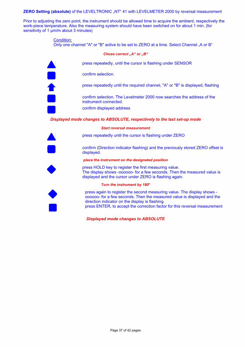
ZERO Setting (absolute) of the LEVELTRONIC „NT“ 41 with LEVELMETER 2000 by reversal measurement Prior to adjusting the zero point, the instrument should be allowed time to acquire the ambient, respectively the work-piece temperature. Also the measuring system should have been switched on for about 1 min. (for sensitivity of 1 µm/m about 3 minutes)
Condition: Only one channel "A" or "B" active to be set to ZERO at a time. Select Channel „A or B“
Chose correct „A“ or „B“
press repeatedly, until the cursor is flashing under SENSOR
confirm selection.
press repeatedly until the required channel, "A" or "B" is displayed, flashing
confirm selection. The Levelmeter 2000 now searches the address of the instrument connected.
confirm displayed address
Displayed mode changes to ABSOLUTE, respectively to the last set-up mode
Start reversal measurement
press repeatedly until the cursor is flashing under ZERO
confirm (Direction indicator flashing) and the previously stored ZERO offset is displayed.
place the instrument on the designated position
press HOLD key to register the first measuring value. The display shows -oooooo- for a few seconds. Then the measured value is displayed and the cursor under ZERO is flashing again.
Turn the instrument by 180°
press again to register the second measuring value. The display shows -oooooo- for a few seconds. Then the measured value is displayed and the direction indicator on the display is flashing.
press ENTER, to accept the correction factor for this reversal measurement
Displayed mode changes to ABSOLUTE
Page 38 of 42 pages
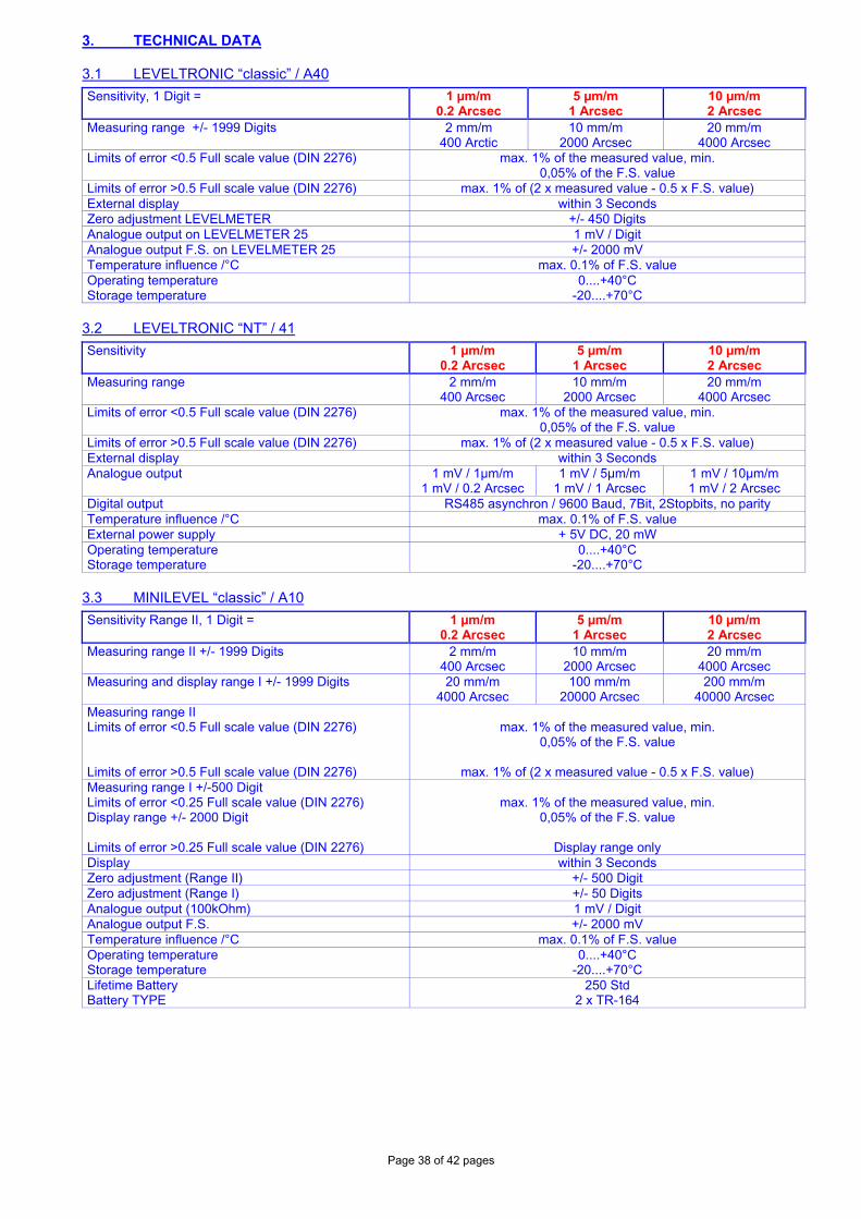
3. TECHNICAL DATA 3.1 LEVELTRONIC “classic” / A40
Sensitivity, 1 Digit = 1 µm/m 0.2 Arcsec
5 µm/m 1 Arcsec
10 µm/m 2 Arcsec
Measuring range +/- 1999 Digits 2 mm/m 400 Arctic
10 mm/m 2000 Arcsec
20 mm/m 4000 Arcsec
Limits of error <0.5 Full scale value (DIN 2276) max. 1% of the measured value, min. 0,05% of the F.S. value
Limits of error >0.5 Full scale value (DIN 2276) max. 1% of (2 x measured value - 0.5 x F.S. value) External display within 3 Seconds Zero adjustment LEVELMETER +/- 450 Digits Analogue output on LEVELMETER 25 1 mV / Digit Analogue output F.S. on LEVELMETER 25 +/- 2000 mV Temperature influence /°C max. 0.1% of F.S. value Operating temperature Storage temperature
0....+40°C -20....+70°C
3.2 LEVELTRONIC “NT” / 41
Sensitivity 1 µm/m 0.2 Arcsec
5 µm/m 1 Arcsec
10 µm/m 2 Arcsec
Measuring range 2 mm/m 400 Arcsec
10 mm/m 2000 Arcsec
20 mm/m 4000 Arcsec
Limits of error <0.5 Full scale value (DIN 2276) max. 1% of the measured value, min. 0,05% of the F.S. value
Limits of error >0.5 Full scale value (DIN 2276) max. 1% of (2 x measured value - 0.5 x F.S. value) External display within 3 Seconds Analogue output 1 mV / 1µm/m
1 mV / 0.2 Arcsec 1 mV / 5µm/m
1 mV / 1 Arcsec 1 mV / 10µm/m 1 mV / 2 Arcsec
Digital output RS485 asynchron / 9600 Baud, 7Bit, 2Stopbits, no parity Temperature influence /°C max. 0.1% of F.S. value External power supply + 5V DC, 20 mW Operating temperature Storage temperature
0....+40°C -20....+70°C
3.3 MINILEVEL “classic” / A10
Sensitivity Range II, 1 Digit = 1 µm/m 0.2 Arcsec
5 µm/m 1 Arcsec
10 µm/m 2 Arcsec
Measuring range II +/- 1999 Digits 2 mm/m 400 Arcsec
10 mm/m 2000 Arcsec
20 mm/m 4000 Arcsec
Measuring and display range I +/- 1999 Digits 20 mm/m 4000 Arcsec
100 mm/m 20000 Arcsec
200 mm/m 40000 Arcsec
Measuring range II Limits of error <0.5 Full scale value (DIN 2276) Limits of error >0.5 Full scale value (DIN 2276)
max. 1% of the measured value, min.
0,05% of the F.S. value
max. 1% of (2 x measured value - 0.5 x F.S. value) Measuring range I +/-500 Digit Limits of error <0.25 Full scale value (DIN 2276) Display range +/- 2000 Digit Limits of error >0.25 Full scale value (DIN 2276)
max. 1% of the measured value, min.
0,05% of the F.S. value
Display range only Display within 3 Seconds Zero adjustment (Range II) +/- 500 Digit Zero adjustment (Range I) +/- 50 Digits Analogue output (100kOhm) 1 mV / Digit Analogue output F.S. +/- 2000 mV Temperature influence /°C max. 0.1% of F.S. value Operating temperature Storage temperature
0....+40°C -20....+70°C
Lifetime Battery Battery TYPE
250 Std 2 x TR-164
Page 39 of 42 pages
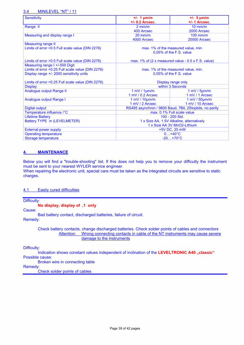
3.4 MINILEVEL “NT” / 11
Sensitivity +/- 1 µm/m +/- 0.2 Arcsec.
+/- 5 µm/m +/- 1 Arcsec.
Range II
2 mm/m 400 Arcsec
10 mm/m 2000 Arcsec
Measuring and display range I 20 mm/m 4000 Arcsec
100 mm/m 20000 Arcsec
Measuring range II Limits of error <0.5 Full scale value (DIN 2276) Limits of error >0.5 Full scale value (DIN 2276)
max. 1% of the measured value, min.
0,05% of the F.S. value
max. 1% of (2 x measured value - 0.5 x F.S. value) Measuring range I +/-500 Digit Limits of error <0.25 Full scale value (DIN 2276) Display range +/- 2000 sensitivity units Limits of error >0.25 Full scale value (DIN 2276)
max. 1% of the measured value, min.
0,05% of the F.S. value
Display range only Display within 3 Seconds Analogue output Range II 1 mV / 1µm/m
1 mV / 0.2 Arcsec 1 mV / 5µm/m
1 mV / 1 Arcsec Analogue output Range I 1 mV / 10µm/m
1 mV / 2 Arcsec 1 mV / 50µm/m
1 mV / 10 Arcsec Digital output RS485 asynchron / 9600 Baud, 7Bit, 2Stopbits, no parity Temperature influence /°C max. 0.1% Full scale value Lifetime Battery Battery TYPE in (LEVELMETER)
100 - 200 Std. 1 x Size AA, 1.5V Alkaline, alternatively
1 x Size AA 3V MnO2-Lithium External power supply +5V DC, 20 mW Operating temperature Storage temperature
0....+40°C -20....+70°C
4. MAINTENANCE Below you will find a "trouble-shooting" list. If this does not help you to remove your difficulty the instrument must be sent to your nearest WYLER service engineer. When repairing the electronic unit, special care must be taken as the integrated circuits are sensitive to static charges. 4.1 Easily cured difficulties
Difficulty: No display, display of ,1 only
Cause: Bad battery contact, discharged batteries, failure of circuit.
Remedy: Check battery contacts, change discharged batteries. Check solder points of cables and connectors
Attention: Wrong connecting contacts in cable of the NT instruments may cause severe damage to the instruments
Difficulty:
Indication shows constant values independent of inclination of the LEVELTRONIC A40 „classic“ Possible cause:
Broken wire in connecting table Remedy:
Check solder points of cables
Page 40 of 42 pages
Difficulty: Zero point unattainable - but instrument operates normally (Sensitivity)
Possible cause: The instrument may have been subjected to a severe shock the zero point is dislocated
in the sensor head.
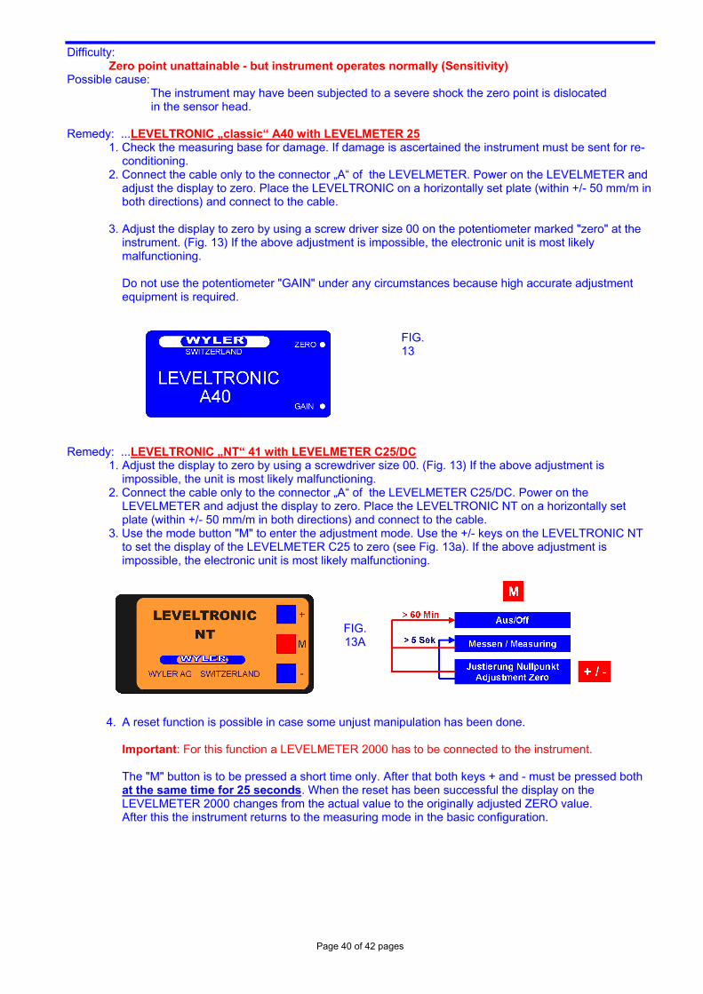
Remedy: ...LEVELTRONIC „classic“ A40 with LEVELMETER 25 1. Check the measuring base for damage. If damage is ascertained the instrument must be sent for re-
conditioning. 2. Connect the cable only to the connector „A“ of the LEVELMETER. Power on the LEVELMETER and
adjust the display to zero. Place the LEVELTRONIC on a horizontally set plate (within +/- 50 mm/m in both directions) and connect to the cable.
3. Adjust the display to zero by using a screw driver size 00 on the potentiometer marked "zero" at the
instrument. (Fig. 13) If the above adjustment is impossible, the electronic unit is most likely malfunctioning.
Do not use the potentiometer "GAIN" under any circumstances because high accurate adjustment equipment is required.
FIG. 13
Remedy: ...LEVELTRONIC „NT“ 41 with LEVELMETER C25/DC
1. Adjust the display to zero by using a screwdriver size 00. (Fig. 13) If the above adjustment is impossible, the unit is most likely malfunctioning.
2. Connect the cable only to the connector „A“ of the LEVELMETER C25/DC. Power on the LEVELMETER and adjust the display to zero. Place the LEVELTRONIC NT on a horizontally set plate (within +/- 50 mm/m in both directions) and connect to the cable.
3. Use the mode button "M" to enter the adjustment mode. Use the +/- keys on the LEVELTRONIC NT to set the display of the LEVELMETER C25 to zero (see Fig. 13a). If the above adjustment is impossible, the electronic unit is most likely malfunctioning.
FIG. 13A
4. A reset function is possible in case some unjust manipulation has been done.
Important: For this function a LEVELMETER 2000 has to be connected to the instrument. The "M" button is to be pressed a short time only. After that both keys + and - must be pressed both at the same time for 25 seconds. When the reset has been successful the display on the LEVELMETER 2000 changes from the actual value to the originally adjusted ZERO value. After this the instrument returns to the measuring mode in the basic configuration.
Page 41 of 42 pages
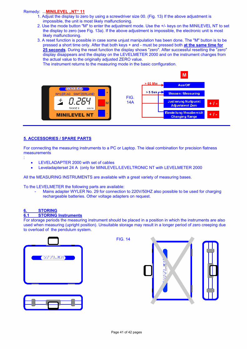
Remedy: ...MINILEVEL „NT“ 11 1. Adjust the display to zero by using a screwdriver size 00. (Fig. 13) If the above adjustment is
impossible, the unit is most likely malfunctioning. 2. Use the mode button "M" to enter the adjustment mode. Use the +/- keys on the MINILEVEL NT to set
the display to zero (see Fig. 13a). If the above adjustment is impossible, the electronic unit is most likely malfunctioning.
3. A reset function is possible in case some unjust manipulation has been done. The "M" button is to be pressed a short time only. After that both keys + and - must be pressed both at the same time for 25 seconds. During the reset function the display shows "zero". After successful resetting the "zero" display disappears and the display on the LEVELMETER 2000 and on the instrument changes from the actual value to the originally adjusted ZERO value. The instrument returns to the measuring mode in the basic configuration.
FIG. 14A
5. ACCESSORIES / SPARE PARTS For connecting the measuring instruments to a PC or Laptop. The ideal combination for precision flatness measurements :
• LEVELADAPTER 2000 with set of cables • Leveladapterset 24 A (only for MINILEVEL/LEVELTRONIC NT with LEVELMETER 2000
All the MEASURING INSTRUMENTS are available with a great variety of measuring bases. To the LEVELMETER the following parts are available:
- Mains adapter WYLER No. 29 for connection to 220V/50HZ also possible to be used for charging rechargeable batteries. Other voltage adapters on request.
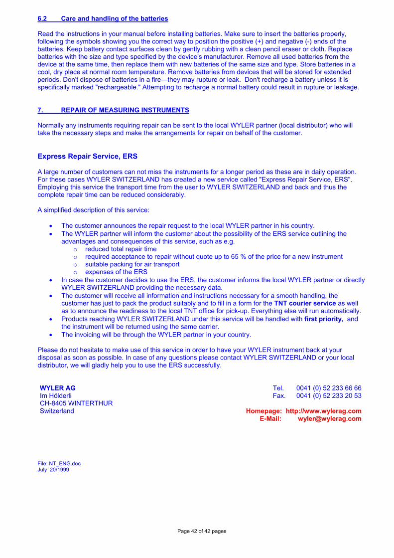
6. STORING 6.1 STORING Instruments For storage periods the measuring instrument should be placed in a position in which the instruments are also used when measuring (upright position). Unsuitable storage may result in a longer period of zero creeping due to overload of the pendulum system.
FIG. 14
Page 42 of 42 pages
6.2 Care and handling of the batteries Read the instructions in your manual before installing batteries. Make sure to insert the batteries properly, following the symbols showing you the correct way to position the positive (+) and negative (-) ends of the batteries. Keep battery contact surfaces clean by gently rubbing with a clean pencil eraser or cloth. Replace batteries with the size and type specified by the device's manufacturer. Remove all used batteries from the device at the same time, then replace them with new batteries of the same size and type. Store batteries in a cool, dry place at normal room temperature. Remove batteries from devices that will be stored for extended periods. Don't dispose of batteries in a fire—they may rupture or leak. Don't recharge a battery unless it is specifically marked "rechargeable." Attempting to recharge a normal battery could result in rupture or leakage. 7. REPAIR OF MEASURING INSTRUMENTS Normally any instruments requiring repair can be sent to the local WYLER partner (local distributor) who will take the necessary steps and make the arrangements for repair on behalf of the customer. Express Repair Service, ERS A large number of customers can not miss the instruments for a longer period as these are in daily operation. For these cases WYLER SWITZERLAND has created a new service called "Express Repair Service, ERS". Employing this service the transport time from the user to WYLER SWITZERLAND and back and thus the complete repair time can be reduced considerably. A simplified description of this service:
• The customer announces the repair request to the local WYLER partner in his country. • The WYLER partner will inform the customer about the possibility of the ERS service outlining the
advantages and consequences of this service, such as e.g. o reduced total repair time o required acceptance to repair without quote up to 65 % of the price for a new instrument o suitable packing for air transport o expenses of the ERS
• In case the customer decides to use the ERS, the customer informs the local WYLER partner or directly WYLER SWITZERLAND providing the necessary data.
• The customer will receive all information and instructions necessary for a smooth handling, the customer has just to pack the product suitably and to fill in a form for the TNT courier service as well as to announce the readiness to the local TNT office for pick-up. Everything else will run automatically.
• Products reaching WYLER SWITZERLAND under this service will be handled with first priority, and the instrument will be returned using the same carrier.
• The invoicing will be through the WYLER partner in your country. Please do not hesitate to make use of this service in order to have your WYLER instrument back at your disposal as soon as possible. In case of any questions please contact WYLER SWITZERLAND or your local distributor, we will gladly help you to use the ERS successfully. WYLER AG Im Hölderli CH-8405 WINTERTHUR Switzerland
Tel. 0041 (0) 52 233 66 66 Fax. 0041 (0) 52 233 20 53
Homepage: http://www.wylerag.com E-Mail: [email protected]
File: NT_ENG.doc July 20/1999