Embed Size (px)
Citation preview

Levitated electromechanics: all-electrical cooling of
charged nano- and micro-particles.
Daniel Goldwater1, Benjamin A. Stickler2, Lukas Martinetz2,
Tracy E. Northup3, Klaus Hornberger2 and James Millen4
1Department of Physics and Astronomy, University College London, Gower Street,
London WC1E 6BT, United Kingdom2University of Duisburg-Essen, Faculty of Physics, Lotharstraße 1, 47048 Duisburg,
Germany.3Institut fur Experimentalphysik, Universitat Innsbruck, Technikerstraße 25, 6020
Innsbruck, Austria.4Department of Physics, King’s College London, Strand, London, WC2R 2LS, UK.
Abstract. We show how charged levitated nano- and micro-particles can be cooled
by interfacing them with an RLC circuit. All-electrical levitation and cooling is
applicable to a wide range of particle sizes and materials, and will enable state-of-
the-art force sensing within an electrically networked system. Exploring the cooling
limits in the presence of realistic noise we find that the quantum regime of particle
motion can be reached in cryogenic environments both for passive resistive cooling and
for an active feedback scheme, paving the way to levitated quantum electromechanics.
arX
iv:1
802.
0592
8v3
[qu
ant-
ph]
23
Jan
2019

Levitated electromechanics: all-electrical cooling of charged nano- and micro-particles.2
1. Introduction
The control of nano- and micro-scale objects in vacuum is of great importance for a
wide range of applications [1], from the study of individual proteins [2], viruses [3] and
bacteria [4], to the simulation of astrophysical processes via the study of dusty plasmas
[5], to the detection of tiny forces [3, 7]. It is predicted that the motion of levitated
nanoparticles can be controlled even at the quantum level [8–11], enabling studies of
macroscopic quantum physics [12], and the contribution of levitated high quality-factor
oscillators in quantum technologies as coherent storage or signal transduction devices.
To achieve quantum control of nano- and micro-particles, their motion must
be cooled towards the quantum regime, which is viable via optical cavity cooling
[1,4,8–11,14,16,17] or parametric feedback [18,19], achieving temperatures below 500µK
(a few tens of motional quanta). However, these optomechanical methods are limited
by the very optical fields that are used for cooling, through optical absorption [6, 21],
photon scattering [19], and instability at low pressures [3–6].
Charged particles can instead be levitated in ion traps [23,24], with trapped atomic
ions at the forefront of quantum information processing technology [25,26]. Their motion
can be detected and cooled via their coupling to the trap electrodes [27, 28], either
resistively or using active feedback methods [29,30]. Extending these techniques to nano-
and micro-particles will enable manipulation and control of massive charged particles
by electronic circuitry. This opens the field of levitated electromechanics, holding the
promise of scalability and network-integration.
In this work, we present an all-electrical levitation, detection and cooling scheme for
charged nano- and micro-particles, which will operate stably under vacuum conditions
while avoiding optical scattering and absorption heating. Our simulations show that
sub-Kelvin particle temperatures are achievable with room temperature circuitry via
resistive and feedback-cooling. The applicable range of sizes, from sub-nanometre
to several micrometres, and materials, including metallic clusters, dielectric particles
and biological objects, illustrates the universality of this technology. Under ambient
conditions, levitated electromechanics will offer a simple and robust pre-cooling method
for optical cavity cooling, and state-of-the-art force sensing. This scheme is suited
to cryogenic environments, where milli-Kelvin temperatures allow reaching the deep
quantum regime.
We first derive the equations-of-motion of a charged particle coupled to an RLC
circuit, and show how they can be quantized. Then we discuss the electronic detection
of motion, followed by the potential to cool through passive-resistive and active-
feedback methods. Finally we discuss the application of levitated electromechanics to
displacement and force sensing.

Levitated electromechanics: all-electrical cooling of charged nano- and micro-particles.3
2. Equations of motion
We consider a spherical particle of mass M and charge q levitated in a potential V (z),
with trapping frequency ωz, which is levitated between plates of separation d and
capacitance C. As illustrated in fig. 1 the two electrodes are joined via an inductance L
to form an LC circuit. While in this work we envision that V (z) is provided by a Paul
trap, with the capacitor formed by the endcap electrodes, we note that the levitating
potential could also be optical. The equations of motion for a charged particle in a
Paul trap are provided in Appendix 1. The interaction with electrostatic mirror charges
formed in the endcap electrodes is negligible for the trap parameters considered below.
The dynamics of the charged particle can be derived using the Shockley-Ramo
theorem [31, 32]. It relates the current I flowing in the circuit with the particle
momentum p = Mz and the voltage drop U across the capacitor. For now we consider
the conservative LC circuit neglecting resistance, yielding
I = −qd
p
M+ CU. (1)
We use the circuit-charge Q on the capacitor as the generalized coordinate of the
circuit, so that the magnetic flux through the inductor Φ = LQ acts as its associated
canonical momentum, and exploit Kirchhoff’s law, U = −Φ, to obtain the canonical
equations-of-motion,
Q =Φ
L(2a)
Φ = − Q
C− q
Cdz. (2b)
The first term in eqn. (2b) gives rise to a harmonic oscillation of frequency
ωLC = 1/√LC, while the second term accounts for the linear coupling to the particle
position z.
The back-action of the circuit dynamics onto the particle motion can be derived by
noting that the voltage offset U across the capacitor induces a constant force −qQ/Cdacting on the particle. Neglecting charging effects due to the formation of mirror charges,
which are on the order of q2/MCd2 ω2z , one thus obtains the equations-of-motion for
the particle:
z =p
M(2c)
p = − ∂zV (z)− q
CdQ. (2d)
Equations (2) describe the coupled classical dynamics of a charged particle trapped
inside an LC circuit. The Hamiltonian function associated with these dynamics can be
identified,
H =Φ2
2L+Q2
2C+
p2
2M+ V (z) +
q
CdQz. (3)

Levitated electromechanics: all-electrical cooling of charged nano- and micro-particles.4
Figure 1. Circuit diagram for the electronic detection of charged particle motion
for an object levitated in a quadrupole ion trap (gray diagram). The motion of the
trapped particle is picked-up by the endcap electrodes separated by d, and induces a
current I in the circuit. A voltage U is generated across the resistance R of the circuit.
Resonant detection is possible by forming either a series or parallel RLC circuit (with
parallel illustrated here), where the capacitance C is due to the trap electrodes plus
any parasitic capacitance.
For harmonic V (z) the particle-circuit system behaves as two linearly coupled harmonic
oscillators.
2.1. Dissipation
We now consider the role of a resistor, of resistance R and temperature TR, connected in
series with the LC circuit. Its action is described by adding the damping and diffusion
term −ΓΦ +√
2ΓLkBTRξ(t) to eqn. (2b). Here, the damping rate of the circuit is
Γ = R/L, and the second term with white noise ξ(t), i.e. 〈ξ(t+τ)ξ(t)〉 = δ(τ), describes
circuit thermalization at temperature T . Due to the linear coupling between the circuit
and the particle (eqn. (3)), the particle will thermalize with the circuit resistance
at temperature TR. The corresponding timescale 1/γ is determined by the circuit
parameters R, L and C as well as by the particle charge q and mass M . Dissipation
in a parallel RLC circuit can be described in a similar fashion by adding a friction and
diffusion term, with parallel friction rate Γ = 1/RC, to the equation-of-motion for the
circuit charge.
2.1.1. Adiabatic damping If the circuit follows the particle motion adiabatically we
can eliminate the former from the equations-of-motion in eqn. (2). Neglecting diffusion
for the moment, one obtains from eqn. (2a) and (2b) the quasi-static expressions for a
series RLC circuit,
Q ' −qdz +
ΓLCq
dMp, (4a)
Φ ' − qL
Mdp. (4b)
These yield the non-conservative equations of motion for the particle,

Levitated electromechanics: all-electrical cooling of charged nano- and micro-particles.5
z =p
M(5a)
p = − ∂zV (z)− ΓLq2
Md2p, (5b)
which allows us to identify the adiabatic damping rate
γad =ΓLq2
Md2. (6)
A similar calculation for the parallel RLC circuit yields γad = 0 since the capacitor
is effectively shorted out in this scenario. In the derivation of eqns. (5) we neglected
the additional attractive force related to the appearance of electrostatic mirror charges.
This contribution is negligible in the present case, and causes a fractional frequency
shift of q2/MCd2ω2z ∼ 10−6.
2.1.2. Damping on resonance If the circuit is on resonance with the particle motion,
ωLC = ωz, the oscillatory dynamics of the particle can effectively cancel the inductance,
leading to a boosted friction rate. This can be made evident by Fourier-transforming
the particle-circuit equations-of-motion for the series RLC circuit and eliminating the
circuit,
ω2z(ω) =
(ω2z +
q2ω2z
MCd2
ω2 − ω2z
(ω2 − ω2z)
2 + ω2Γ2
)z(ω) + i
q2ω2z
MCd2
ωΓ
(ω2 − ω2z)
2 + ω2Γ2z(ω).
(7)
For Γ2 |ω2 − ω2z |, this equation yields the on-resonance particle friction rate
γres =q2
MCΓd2, (8)
which increases with decreasing circuit dissipation. A similar calculation for the parallel
RLC circuit yields the same result for the friction rate. This resonant enhancement of
friction is in agreement with the damping rate observed for trapped atomic ions and
electrons [33,34]. Note that the series adiabatic friction rate (6) is equal to the parallel
on-resonance damping rate (8).
2.2. Quantum dynamics
We consider the situation where particle and circuit are cooled to their ground-state or
close to it. The coupled quantum dynamics of the combined particle-series RLC circuit
state ρ can be modeled by the Linblad master equation [35],
∂tρ = − i~
[H, ρ]− iΓ
4~[Q,Φ , ρ] +
Γ
2
(LρL† − 1
2
L†L, ρ
), (9)

Levitated electromechanics: all-electrical cooling of charged nano- and micro-particles.6
where H is the quantized Hamiltonian eqn. (3) (operators are denoted by sans-serif
characters), and the Lindblad operators are
L =
√4LkBTR~
Q +i√
4LkBTRΦ. (10)
The completely positive master equation (9) describes the Markovian thermaliza-
tion dynamics of the particle-circuit state ρ. For large circuit temperatures, where the
term proportional to 1/TR can be neglected, one obtains
∂tρ = − i~
[H, ρ] +Γ
2i~[Q, Φ, ρ]− ΓLkBTR
~2[Q, [Q, ρ]] . (11)
The second term on the right hand side describes damping of the circuit momentum
Φ with friction rate Γ, while the third term describes charge diffusion. The corresponding
diffusion constant ΓLkBTR is in accordance with the fluctuation-dissipation relation.
If the trapping potential is harmonic the master equation describes thermalization
towards the Gibbs equilibrium ρeq = exp(−H/kBTR)/Z, and the expectation values
of the canonical phase-space observables exhibit the classical thermalization dynamics
(eqns. (2)).
3. Detection of the particle motion
Experiments demonstrating trapping of single electrons [36,37], ions [38] and protons [30]
as well as electron [27] and proton [39] clouds, have noted that it is possible to detect the
classical motion of the charged particle(s) via the image current I that they generate
in the endcap electrodes of Paul or Penning traps [33]. We now show that this is
also possible for spherical nano- and micro-scale particles. Under the assumption that
Γ ωz the circuit adiabatically follows the particle motion, and eqn. (1) reduces in
lowest order of the particle velocity to
I = −qηdz, (12)
where we have introduced the geometrical factor η to account for the shape of the pick-
up electrodes, which we assign the realistic value of η = 0.8 for slightly parabolically
shaped electrodes [28]. The maximum velocity given by the equipartition theorem is
zmax =√kBTCM/M , where TCM is the centre-of-mass temperature of the particle. This
implies a peak induced current of
Imax =qη
d
√kBTCM
M. (13)
The scaling Imax ∝ q/√M is favourable when working with highly charged massive
particles. A silica sphere of radius rS = 1µm (M = 5.5× 10¹² amu) and realistic charge
q = 106 e (Appendix 2), where e is the elementary charge, will induce a comparable
current to the atomic ion 88Sr+.

Levitated electromechanics: all-electrical cooling of charged nano- and micro-particles.7
10 2 10 3 10 410 -2
10 -1
10 0
10 1
10 2
10 3
10 4 10 5 10 6
-100
0
100
0 50 100 150 200
-100
0
100
a) b)
Figure 2. Resistive cooling: a) Variation in the momentum damping rate γ of a
charged particle coupled to a circuit, with resistor value R and particle charge q (open
circles: simulation eqn. (26), solid lines: eqn. (14)). b) Simulated particle trajectories
for two different circuit temperatures TR, illustrating that the particle thermalizes with
the circuit. The parameters in this figure unless stated otherwise are: Tin = 1000 K,
rS = 1µm, q = 105 e, d = 1 mm, Qf = 100, R = 100 MΩ, TR = 300 K.
4. Resistive cooling
As demonstrated in Sec. 2.1, connecting the endcap electrodes to an RLC circuit serves
to dissipate the induced current and thus damp the particle motion. The ensuing friction
rate (8) on resonance (ωLC = ωz) can be written as
γres =(qηd
)2 Reff
M, (14)
where we introduced the effective resistance Reff [28, 34]. For a series RLC circuit
Reff = Q2fR, while for parallel it reads Reff = ωzLQf , with the circuit quality factor
Qf = ωz/Γ.
Tuned circuits with Qf = 25, 000 have been used to cool N+2 ions [40], and it
is proposed to exploit high Qf quartz crystal oscillators connected in parallel with the
endcaps to further boost resistive cooling [41]. For a modest Qf = 100 and R = 100 MΩ,
an rS = 1µm, q = 106 e silica sphere at room temperature would generate a signal of
∼ 100 mV for electrodes separated by 1 mm.
Resistive cooling is illustrated in fig. 2, where the motion of a charged microsphere
in a quadrupole ion trap is numerically simulated including all sources of noise, as
outlined in Appendix 1. From eqn. 14, it is clear that to increase the damping rate, one
can increase Reff or q, as verified in fig. 2 a), where eqn. 14 is compared to the results
of the numerical simulation, with the agreement illustrating that realistic experimental
noise has little effect on the damping rate. The scaling of the damping rate γ ∝ q2/M
is favourable for highly-charged massive particles.
The dissipation of energy across R is accompanied by heating due to Johnson-
Nyquist noise [28, 33, 34], modeled as a white voltage-noise source VR of width

Levitated electromechanics: all-electrical cooling of charged nano- and micro-particles.8
Figure 3. Circuit diagram for the feedback control of charged particle motion.
The motion of the particle induces a voltage U across the effective resistance Reff . An
amplifier of gain G feeds this voltage back onto one of the endcap electrodes, effectively
shorting out the Johnson-Nyquist noise at G = 1. The feedback amplifier introduces
voltage noise Vfb.
√4kBTRReff , where TR is the temperature of the circuit. For a description of how noise
is added to the simulations of trapped particle motion, see Appendix 1. In the absence
of other noise sources, the particle will equilibrate to the temperature of the circuit TR,
as indicated by the thermal trajectory in fig. 2b). Hence, to reach low temperatures via
resistive cooling, cryogenic circuitry is required [34]. Note that it is possible to design
ion trap geometries to resistively cool all three degrees-of-freedom, for example by using
a ring electrode which is split into segments [28,42].
Even under ambient conditions, resistive cooling can be useful to stabilize trapped
particles, for example against collisions with residual gas molecules [3, 4, 6], or to pre-
cool massive particles, which in general possess initial motional energies far above room
temperature due the loading mechanism [1, 43]. Furthermore, avoiding optical fields
removes motional heating due to scattering of photons.
To consider the limits of resistive cooling, we consider operation in a state-of-
the-art dilution refrigerator at 5 mK. By considering the quadrupole ion trap stability
parameters, as defined by eqn. (23) in Appendix 1, an rS = 1µm silica sphere with
q = 106 e can have stable frequencies of ωz > 2π × 1 MHz, which would correspond to
reaching a phonon occupancy of n = kBTCM/(~ωz) < 100.
5. Feedback cooling
Since we can detect the motion of a charged particle via the endcap voltage U , we
can feed this signal back onto the endcaps to dynamically control the particle’s motion.
Figure 3 shows a schematic of this process, where an amplifier with gain G generates the
voltage GU on the lower endcap electrode. With the appropriate phase shift between
U and GU , this either amplifies or cools the motion [29,38,44].
In the scenario depicted in fig. 3, the charged particle sees a voltage Ufb which is

Levitated electromechanics: all-electrical cooling of charged nano- and micro-particles.9
-100
0
100
-100
0
100
0 100 200 300 400 500
-100
0
100
0 0.2 0.4 0.6 0.8 10
100
200
300
400
10 -12 10 -8 10 -4
10 -2
10 0
10 2
10 4
a) b)
c)
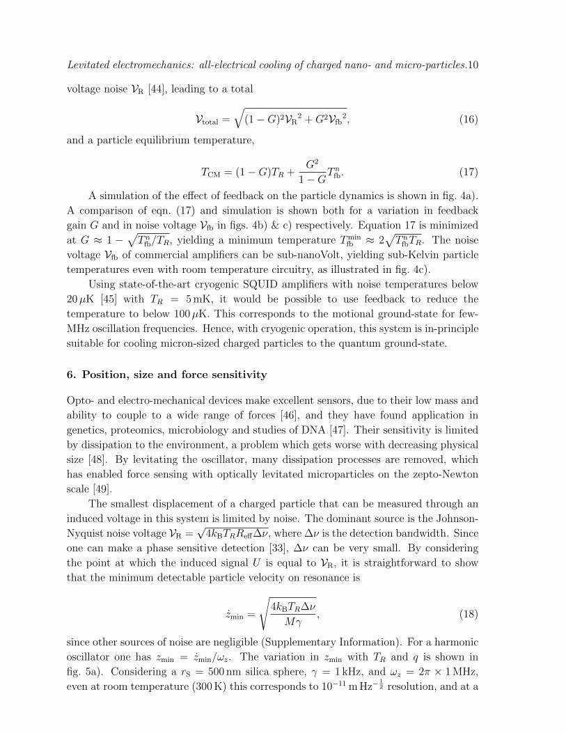
Figure 4. Feedback cooling: a) Simulated particle trajectories showing the effect
of feedback gain G. Variation in simulated particle equilibrium temperature TCM
with b) amplifier gain G (open circles: simulation eqn. (26), solid line: eqn. (17),
disagreement due to the finite run-time of the simulations), and c) feedback amplifier
noise voltage Vfb at two different circuit temperatures TR, with G = 0.95 (open circles:
simulation eqn. (26), solid line: eqn. (17)). The parameters in this figure unless stated
otherwise are: Tin = 1000 K, rS = 1µm, q = 105 e, d = 1 mm, Qf = 100, R = 100 MΩ,
Vfb = 10−10 V, TR = 300 K.
generated by the voltage difference between the two endcap electrodes:
Ufb = (1−G)U. (15)
At G = 1 the circuit resistance that the particle sees Rfb = (1 − G)Reff and the
thermal noise is tuned out. Explicitly, in this simple model the temperature TCM of
the particle is reduced to TCM = (1 − G)TR. Simultaneously, the feedback damping
rate γfb ∝ Rfb goes to zero as G approaches unity, γfb = (1 − G)γ. Charged nano-
and micro-particles are stable in Paul traps on the timescale of months [1], somewhat
negating the necessity for rapid damping in the absence of other noise sources.
For a more realistic description, it is necessary to include the voltage noise added
by the feedback amplifier Vfb, as illustrated in fig. 3. Noise added due to collisions
with gas molecules and electrode surface potentials is considered in the Supplementary
Information, and included in the simulations of the particle motion presented in figs. 2
& 4, and can be neglected. This noise voltage has an associated noise temperature T nfb
defined through Vfb =√
4kBT nfbRampB, where Ramp is the resistance of the feedback
amplifier, and B is its bandwidth. This noise adds in quadrature with the uncorrelated
Levitated electromechanics: all-electrical cooling of charged nano- and micro-particles.10
voltage noise VR [44], leading to a total
Vtotal =
√(1−G)2VR
2 +G2Vfb2, (16)
and a particle equilibrium temperature,
TCM = (1−G)TR +G2
1−GT n
fb. (17)
A simulation of the effect of feedback on the particle dynamics is shown in fig. 4a).
A comparison of eqn. (17) and simulation is shown both for a variation in feedback
gain G and in noise voltage Vfb in figs. 4b) & c) respectively. Equation 17 is minimized
at G ≈ 1 −√T n
fb/TR, yielding a minimum temperature Tminfb ≈ 2
√T n
fbTR. The noise
voltage Vfb of commercial amplifiers can be sub-nanoVolt, yielding sub-Kelvin particle
temperatures even with room temperature circuitry, as illustrated in fig. 4c).
Using state-of-the-art cryogenic SQUID amplifiers with noise temperatures below
20µK [45] with TR = 5 mK, it would be possible to use feedback to reduce the
temperature to below 100µK. This corresponds to the motional ground-state for few-
MHz oscillation frequencies. Hence, with cryogenic operation, this system is in-principle
suitable for cooling micron-sized charged particles to the quantum ground-state.
6. Position, size and force sensitivity
Opto- and electro-mechanical devices make excellent sensors, due to their low mass and
ability to couple to a wide range of forces [46], and they have found application in
genetics, proteomics, microbiology and studies of DNA [47]. Their sensitivity is limited
by dissipation to the environment, a problem which gets worse with decreasing physical
size [48]. By levitating the oscillator, many dissipation processes are removed, which
has enabled force sensing with optically levitated microparticles on the zepto-Newton
scale [49].
The smallest displacement of a charged particle that can be measured through an
induced voltage in this system is limited by noise. The dominant source is the Johnson-
Nyquist noise voltage VR =√
4kBTRReff∆ν, where ∆ν is the detection bandwidth. Since
one can make a phase sensitive detection [33], ∆ν can be very small. By considering
the point at which the induced signal U is equal to VR, it is straightforward to show
that the minimum detectable particle velocity on resonance is
zmin =
√4kBTR∆ν
Mγ, (18)
since other sources of noise are negligible (Supplementary Information). For a harmonic
oscillator one has zmin = zmin/ωz. The variation in zmin with TR and q is shown in
fig. 5a). Considering a rS = 500 nm silica sphere, γ = 1 kHz, and ωz = 2π × 1 MHz,
even at room temperature (300 K) this corresponds to 10−11 m Hz−12 resolution, and at a

Levitated electromechanics: all-electrical cooling of charged nano- and micro-particles.11
10 -2 10 0 10 2
10 -16
10 -14
10 -12
10 -9 10 -7 10 -5
10 -24
10 -20
10 -16
10 -12
a) b)
Figure 5. Sensing: a) Minimum detectable particle displacement with a 1 Hz
measurement bandwidth as a function of the circuit temperature TR, for two different
values of particle charge q, with ωz = 2π × 1 MHz. b) Minimum detectable force
with a 1 Hz measurement bandwidth, as a function of particle size rS (silica sphere),
for two different circuit temperatures TR, assuming that the particle thermalises with
the circuit. The parameters in this figure unless stated otherwise are: rS = 1µm,
d = 1 mm, Qf = 100, R = 100 MΩ.
cryogenic temperature of 5 mK, < 10−15 m Hz−12 resolution. The zero-point fluctuation
of such a particle is zzpf =√~/2Mωz = 8× 10⁻¹⁵ m.
When considering the force sensitivity of a harmonic oscillator, the minimum
detectable force is Fmin =√
4kBTCMMγCM∆ν, where γCM is the damping rate on its
motion [49]. In our case, the dominant damping without feedback is resistive γ, as
defined in eqn. (14). This cannot be made arbitrarily low, since small γ means we
detect less signal U , which must in turn be greater than the noise voltage VR. Hence,
we have the requirement,
IReff >√
4kBTRReff∆ν. (19)
Using eqns. (13) & (14), and assuming that the particle is in thermal equilibrium
with the circuit TCM = TR, we find the simple expression γ > 4∆ν, which is the value of
the resistive damping required to measure above the thermal noise in a given bandwidth.
In other words, the measurement time must be on the order of the ring-down time (1/γ).
This yields a force sensitivity
Fmin = γ√kBTRM. (20)
The variation in Fmin with particle size and temperature is shown in fig. 5b).
Practically, choosing a low value of γ will lead to long thermalisation times, requiring a
stable experiment, although particles in ion traps are stable on month-timescales. Using
eqn. (20), with a 1 Hz measurement bandwidth, for an rS = 100 nm silica sphere, Fmin at
300 K is 8× 10⁻¹⁹ N, and at 5 mK is 3× 10⁻²¹ N, comparable to state-of-the-art optical
systems [49]. It is worth noting that it is possible to levitate lower-mass particles in an

Levitated electromechanics: all-electrical cooling of charged nano- and micro-particles.12
ion trap than optically, due to an increased trap depth, making the electromechanical
system attractive for sensing applications.
Finally, using eqns. (13) & (19), it is possible to detect particles which satisfy the
following relation,
q√M
>
√2∆ν
Reff
d
η. (21)
As an example, this means that using realistic experimental parameters (R =
100 MΩ, Qf = 100, η = 0.8, d = 1 mm, ∆ν = 1 Hz), it would be possible to detect
singly charged particles with masses up to 5× 10⁶ amu.
7. Discussion
We have demonstrated that levitated electromechanics, where charged particles levitated
in an ion trap are interfaced with an RLC circuit, can be used for electronic
detection, cooling and precision sensing. Using feedback, sub-Kelvin temperatures are
achievable with room temperature circuitry, and we predict that working in a cryogenic
environment will enable ground-state cooling for micron-sized particles.
Levitated electromechanics is compatible with optomechanical systems. A hybrid
levitated opto-/electro-mechanical is suitable for cooling deep into the quantum regime,
and for the production of interesting mechanical quantum states, such as squeezed
states [50]. Charged particles equilibrate with the trapping circuitry, which acts as
a highly controllable thermal bath, making the system suitable for studies of low-
dissipation thermodynamics [51].
Acknowledgments
JM is grateful for discussions with Andrew Geraci, and for funding from EPSRC
project EP/S004777/1. DG would like to thank Peter Barker for useful discussions,
and is supported by the Controlled Quantum Dynamics Centre for Doctoral
Training at Imperial College London. BS acknowledges support by Deutsche
Forschungsgemeinschaft (DFG – 411042854). TN acknowledges support from Austrian
Science Fund (FWF) Projects Y951-N36 and F4019-N23.
Appendix 1: Equations of motion in a quadrupole ion trap
For the purposes of this work, we consider only motion along the z-axis between the
endcap electrodes of a spherical quadrupole ion trap. The equation-of-motion when
driven by a voltage UAC(t) = UDC + U0 cos(ωDt) is
Mz − Mω2D
4[az − 2qz cos(ωDt)]z = 0, (22)

Levitated electromechanics: all-electrical cooling of charged nano- and micro-particles.13
where ωD is the drive frequency, and az, qz are stability parameters,
az =4UDCηq
Mω2Dr
20
qz = − 2U0ηq
Mω2Dr
20
, (23)
with η = 0.8 is a geometric factor, M the mass of the particle, and 2r0 the separation
between the RF electrodes (or the diameter of the ring electrode). In what follows, we
set UDC = 0 (and hence az = 0). This yields a secular frequency in the z-direction of
ωz = ωDqz/2√
2.
Feedback, as discussed in Sec. 5, acts as a force proportional to the velocity z,
since it depends on the induced current I (see eqn. (12)). Hence, with feedback, the
equation-of-motion reads:
Mz +Mγfbz +Mω2
D
2qz cos(ωDt)z = 0. (24)
Inclusion of noise
We consider the influence of several noise sources: gas collisions at temperature Tgas
through the damping rate γgas (see Supplementary Information); the Johnson-Nyquist
noise of the circuit at the temperature TR through the rate γ; and the noise of the
feedback amplifier Vfb with associated noise temperature T nfb and damping rate γfb.
We include each of these in our model via the fluctuation-dissipation theorem,
〈Fgas(t+ τ)Fgas(t)〉 = 2kBTgasγgasMδ(τ)
〈FR(t+ τ)FR(t)〉 = 2kBTRγMδ(τ)
〈F nfb(t+ τ)F n
fb(t)〉 = 2kBTnfbγfbMδ(τ),
(25)
for the gas, resistive, and feedback random force respectively.
The electrode surface noise, which is discussed in detail in the Supplementary
Information, is included by considering the fluctuating force 〈FE(t + τ)FE(t)〉 =
q2SE(ωz)δ(t− τ), constructed noting that an electric field E generates a force qE on a
particle of charge q.
Hence, the full equation-of-motion for the z-direction reads:
Mz +M(γgas + γres + γfb)z +Mω2
D
2qz cos(ωDt)z = Fgas + Fres + Fn,fb + FE. (26)
Appendix 2: Charging the particles
The resistive and feedback damping rates depend on the charge q of the trapped particle.
A dielectric particle of radius rS can hold a maximal negative charge [52] of about
qneg
e= −1− 0.7
( rS
nm
)2
, (27)

Levitated electromechanics: all-electrical cooling of charged nano- and micro-particles.14
and a maximal positive charge of [52]
qpos
e= 1 + 21
( rS
nm
)2
. (28)
This implies that a rS = 1µm particle can hold up to 2 × 10⁷ positive charges.
Practically, 5µm diameter melamine particles have been charged via positive ion
bombardment (5 keV He ions) to hold∼ 7×10⁶ |e| [53], significantly below the theoretical
limit in eq. (28).
Charging can be achieved via electron or ion bombardment [53–55], corona
discharge [56] and adhesion of charged droplets. Not much is known about the charging
limits for sub-micron particles, but it has been noted that, for smaller particles,
secondary emission of charge from the bulk material can limit the maximum surface
potential [55,57]. Smaller spheres require higher electric fields to charge, as determined
by the Pauthenier equation [56], which says that in a uniform electric field E, the
maximum charge held by a sphere is
qmax = 4πε0r2SpE, (29)
where p = 3 for a conductor, and p = 3εr/(εr + 2) for a dielectric. Low charges on
nano- [58] and micro-particles [54] are stable over timescales of hours.
References
[1] S. Maher, F. P. M. Jjunju and S. Taylor, “Colloquium: 100 years of mass spectrometry:
Perspectives and future trends”, Rev. Mod. Phys. 87, 113 (2015).
[2] J. E. Bruce, X. Cheng, R. Bakhtiar, Q. Wu, S. A. Hofstadler, G. A. Anderson and R. D. Smith,
“Trapping, Detection, and Mass Measurement of Individual Ions in a Fourier Transform Ion
Cyclotron Resonance Mass Spectrometer”, J. Am. Chem. Soc. 116, 7839-7847 (1994).
[3] S. D. Fuerstenau, W. H. Benner, J. J. Thomas, C. Brugidou, B. Bothner and G. Siuzdak, “Mass
Spectrometry of an Intact Virus”, Angew. Chem. Int. Ed. 113, 559-562 (2001).
[4] W. P. Peng, Y. C. Yang, M. W. Kang, Y. T. Lee and H. C. Chang, “Measuring masses of single
bacterial whole cells with a quadrupole ion trap”, J. Am. Chem. Soc. 126, 11766-11767 (2004).
[5] G. E. Morfill and A. V. Ivlev, “Complex plasmas: An interdisciplinary research field”, Rev. Mod.
Phys. 81, 1353-1404 (2009).
[6] G. Ranjit, D. P. Atherton, J. H. Stutz, M. Cunningham and A. A. Geraci, “Attonewton force
detection using microspheres in a dual-beam optical trap in high vacuum”, Phys. Rev. A 91,
051805 (2015).
[7] S. Kuhn, B. A. Stickler, A. Kosloff, F. Patolsky, K. Hornberger, M. Arndt and J. Millen, “Optically
driven ultra-stable nanomechanical rotor”, Nature Commun. 8, 1670 (2017).
[8] D. E. Chang et al., “Cavity opto-mechanics using an optically levitated nanosphere”, Proc. Natl
Acad. Sci. USA 107, 1005 (2010).
[9] P. F. Barker and M. N. Schneider, “Cavity cooling of an optically trapped nanoparticle”, Phys.
Rev. A 81, 023826 (2010).
[10] O. Romero-Isart, M. Juan, R. Quidant and J. Cirac, “Toward quantum superposition of living
organisms”, New J. Phys. 12, 033015 (2010).
[11] B. A. Stickler et al., “Ro-Translational Cavity Cooling of Dielectric Rods and Disks”, Phys. Rev.
A 94, 033818 (2016).

Levitated electromechanics: all-electrical cooling of charged nano- and micro-particles.15
[12] M. Arndt and K. Hornberger, “Insight review: Testing the limits of quantum mechanical
superpositions”, Nature Phys. 10, 271–277 (2014).
[13] N. Kiesel et al., “Cavity cooling of an optically levitated submicron particle”, Proc. Natl. Acad.
Sci. USA 110, 14180-14185 (2013).
[14] P. Asenbaum, S. Kuhn, S. Nimmrichter, U. Sezer and M. Arndt, “Cavity cooling of free silicon
nanoparticles in high-vacuum”, Nat. Commun. 4, 2743 (2013).
[15] J. Millen, P. Z. G. Fonseca, T. Mavrogordatos, T. S. Monteiro and P. F. Barker, “Cavity Cooling
a Single Charged Levitated Nanosphere”, Phys. Rev. Lett. 114, 123602 (2015).
[16] S. Kuhn et al., “Nanoparticle detection in an open-access silicon microcavity”, Appl. Phys. Lett.
111, 253107 (2016).
[17] P. Z. G. Fonseca, E. B. Aranas, J. Millen, T. S. Monteiro and P.F. Barker, “Nonlinear dynamics
and strong cavity cooling of levitated nanoparticles”, Phys. Rev. Lett. 117, 173602 (2016).
[18] J. Gieseler, B. Deutsch, R. Quidant and L. Novotny, “Subkelvin parametric feedback cooling of a
laser-trapped nanoparticle”, Phys. Rev. Lett. 109, 103603 (2012).
[19] V. Jain, J. Gieseler, C. Moritz, C. Dellago, R. Quidant and L. Novotny “Direct measurement of
photon recoil from a levitated nanoparticle”, Phys. Rev. Lett. 116, 243601 (2016).
[20] J. Millen, T. Deesuwan, P. F. Barker and J. Anders, “Nanoscale temperature measurements using
non-equilibrium Brownian dynamics of a levitated nanosphere”, Nature Nano. 9, 425-429 (2014).
[21] E. Hebestreit, R. Reimann, M. Frimmer and L. Novotny, “Measuring the Internal Temperature of
a Levitated Nanoparticle in High Vacuum”, Phys. Rev. A 97, 043803 (2018).
[22] J. Vovrosh, M. Rashid, D. Hempston, J. Bateman, M. Paternostro and H. Ulbricht, “Parametric
feedback cooling of levitated optomechanics in a parabolic mirror trap”, J. Opt. Soc. Am. B 34,
1421-1428 (2017).
[23] W. Paul and H. Steinwedel, “Ein neues Massenspektrometer ohne Magnetfeld”, Z. Naturforsch.
A 8, 448-450 (1953).
[24] W. Paul, “Electromagnetic traps for charged and neutral particles”, Rev. Mod. Phys. 62, 531
(1990).
[25] L.-M. Duan and C. Monroe, “Colloquium: Quantum networks with trapped ions”, Rev. Mod. Phys.
82, 1209 (2010).
[26] K. Singer et al., “Colloquium: Trapped ions as quantum bits: Essential numerical tools”, Rev.
Mod. Phys. 82, 2609 (2010).
[27] D. Wineland and H. G. Dehmelt, “Principles of the stored ion calorimeter”, J. Appl. Phys. 46,
919 (1975).
[28] W. M. Itano, J. C. Bergquist, J. J. Bollinger and D. J. Wineland, “Cooling methods in ion traps”,
Phys. Scr. 1995, 106 (1995).
[29] B. D’Urso, B. Odom and G. Gabrielse, “Feedback Cooling of a One-Electron Oscillator”, Phys.
Rev. Lett. 90, 043001 (2003).
[30] N. Guise, J. DiSciacca and G. Gabrielse, “Self-Excitation and Feedback Cooling of an Isolated
Proton”, Phys. Rev. Lett. 104, 143001 (2010).
[31] W. Shockley, “Currents to conductors induced by a moving point charge”, J. Appl. Phys. 10,
635–636 (1938).
[32] Sirkis, Murray D and Holonyak Jr, Nick, “Currents induced by moving charges”, Am. J. Phys.
10, 943–946 (1966).
[33] L. S. Brown and G. Gabrielse, “Geonium theory: Physics of a single electron or ion in a Penning
trap”, Rev. Mod. Phys. 58, 233 (1986).
[34] S. Di Domizio, D. Krasnick, V. Lagomarsino, G. Testera, R. Vaccaronea and S. Zavatarellia,
“Toward sub-Kelvin resistive cooling and non destructive detection of trapped non-neutral
electron plasma”, JINST 10, P01009 (2015).
[35] Breuer, H.-P. and Petruccione, F., “The theory of open quantum systems”, Oxford University
Press (2002).
[36] D. Wineland, P. Ekstrom and H. Dehmelt, “Monoelectron Oscillator”, Phys. Rev. Lett. 31, 1279

Levitated electromechanics: all-electrical cooling of charged nano- and micro-particles.16
(1973).
[37] B. D’Urso, R. Van Handel, B. Odom, D. Hanneke and G. Gabrielse, “Single-Particle Self-Excited
Oscillator”, Phys. Rev. Lett. 94, 113002 (2005).
[38] H. Dehmelt, W. Nagourney and J. Sandberg “Self-excited mono-ion oscillator”, Proc. Natl. Acad.
Sci. USA 83, 5761-5763 (1986).
[39] D. A. Church and H. G. Dehmelt, “Radiative Cooling of an Electrodynamically Contained Proton
Gas”, J. Appl. Phys. 40, 3421-3424 (1969).
[40] E. A. Cornell et al., “Single-ion cyclotron resonance measurement of M(CO+)/M(N+2 )”, Phys. Rev.
Lett. 63, 1674 (1989).
[41] T. Kaltenbacher, F. Caspers, M. Doser, A. Kellerbauer and W. Pribyl, “Resistive cooling circuits
for charged particle traps using crystal resonators”, Rev. Sci. Instrum. 82, 114702 (2011).
[42] G. Zs. K. Horvath, R. C. Thompson and P. L. Knight, “Fundamental physics with trapped ions”,
Contemporary Physics 38, 25-48 (1997).
[43] J. Millen, S. Kuhn, F. Patolsky, A. Kosloff and M. Arndt, “Cooling and manipulation of
nanoparticles in high vacuum,” Proc. SPIE 9922, 99220C (2016).
[44] B. D’Urso, “Cooling and Self-Excitation of a One-Electron Oscillator”, Ph. D. Thesis, Harvard
University (2003).
[45] A. Vinante, R. Mezzena, G. A. Prodi and S. Vitale, ‘Dc superconducting quantum interference
device amplifier for gravitational wave detectors with a true noise temperature of 16 µK”, Appl.
Phys. Lett. 79, 2597 (2001).
[46] M. Metcalfe, “Applications of cavity optomechanics”, Appl. Phys. Rev. 1, 031105 (2014).
[47] M. Calleja, P. M. Kosaka, A. San Paulo and J. Tamayo, “Challenges for nanomechanical sensors
in biological detection”, Nanoscale 4, 4925 (2012).
[48] K. L. Ekinci and M. L. Roukes, “Nanoelectromechanical systems”, Rev. Sci. Instrum. 76, 061101
(2015).
[49] G. Ranjit, M. Cunningham, K. Casey and A. A. Geraci, “Zeptonewton force sensing with
nanospheres in an optical lattice”, Phys. Rev. A 93, 053801 (2016).
[50] M. G. Genoni, J. Zhang, J. Millen, P. F. Barker and A. Serafini, “Quantum cooling and squeezing
of a levitating nanosphere via time-continuous measurements”, New J. Phys. 17, 073019 (2015).
[51] J. Millen and J. Gieseler, “Levitated Nanoparticles for Microscopic ThermodynamicsA Review”,
Entropy 20, 326 (2018).
[52] B. T. Draine and B. Sutin, “Collisional charging of interstellar grains”, ApJ 320, 803 (1987).
[53] A. Velyhan, P. Zilavy, J. Pavlu, J. Safrankova and Z. Nemecek, “Ion beam effects on dust grains”,
Vacuum 76, 447 (2004).
[54] S. Schlemmer, J. Illemann, S. Wallert and D. Gerlich, “Nondestructive high-resolution and absolute
mass determination of single charged particles in a three-dimensional quadrupole trap”, J. Appl.
Phys. 90, 5410-5418 (2001).
[55] S. I. Kopnin, T. I Morozova and S. I . Popel, “Electron Beam Action and High Charging of Dust
Particles”, IEEE T. Plasma Sci. 99, 1-3 (2017).
[56] K. Adamiak, “Rate of charging of spherical particles by monopolar ions in electric fields”, IEEE
Transactions on Industry Applications 38, 1001-1008 (2002).
[57] I. Cermak, E. Grun and J. Svestka, “New results in studies of electric charging of dust particles”,
Adv. Space Res. 15, 59-64 (1995).
[58] M. Frimmer, K. Luszcz, S. Ferreiro, V. Jain, E. Hebestreit and L. Novotny, “Controlling the net
charge on a nanoparticle optically levitated in vacuum”, Phys. Rev. A 95, 061801 (2017).

Levitated electromechanics: all-electrical cooling of charged nano- and micro-particles.1
-0.1
0
0.1
0 5 10
-0.1
0
0.1
10 1 10 3 10 510 -30
10 -25
10 -20
10 -15
10 -6 10 -4 10 -2 10 0 10 2
300
400
500
600
700
800
900a) b) c)
Figure 1. Background gas pressure: a) Simulated particle trajectories at two
different gas pressures P . b) Simulated PSD of motion for different P . c) Variation
in particle temperature TCM after 500 ms with P , for an initial particle temperature
Tin = 1000K and gas temperature Tgas = 300K, showing that at higher pressures
the particle rapidly thermalises with the gas (simulation: open circles, theory (300 K):
solid line). Feedback gain G = 0 for these simulations, q = 105 e, R = 100 Ω, Qf = 100,
TR = 300 K.
Supplementary Information
Interaction with residual gas
In discussions of cooling ions or electrons, it is assumed that the background pressure
is as low as possible, since gas collisions lead to trap loss. This is not necessarily true
for much more massive nano- and micro-particles, where collisions with background gas
lead to thermalization with the environmental temperature Tgas. Indeed, in nano- and
micro-particle trapping experiments, this dissipation process is necessary for loading
conservative trapping potentials, with loading pressures ranging from 0.1 mbar [1],
3 mbar [2], 10 mbar [3], to atmospheric [4]. Furthermore, nano- and micro-particles
in optical traps are observed to be unstable below pressures ranging from 10−5 mbar [5]
to ≈ 1 mbar [3, 4, 6].
The damping rate on a sphere of radius rS is [6, 7]:
γgas =4π
3
mngasr2Svth
M, (S1)
where m is the mass of the gas molecules, ngas is the number density of the gas, vth
is the mean gas thermal velocity, and M is the mass of the sphere. As a sense of
scale, for a rS = 1µm silica sphere, at a pressure of 100 mbar (N2), γgas ∼ 104 Hz, and
at 10−8 mbar, γgas ∼ 10−6 Hz. This means that, when working at UHV, even modest
cooling rates overcome heating due to gas collisions. Figure 1 shows simulations of the
effect of residual gas on trapped particle dynamics.

Levitated electromechanics: all-electrical cooling of charged nano- and micro-particles.2
-1
0
1
0 5 10-2
0
2
10 3 10 4 10 510 -35
10 -30
10 -25
10 -20
10 -5 10 -4 10 -3
0
50
100
150
a) b) c)
Figure 2. Electrode noise: The effect of electrode surface noise is explored through
simulation by varying the trap-centre to endcap electrode spacing r′. a) Simulated
particle trajectories for two different values of r′. b) Simulated PSD of particle motion
for different r′. c) Simulated particle temperature as r′ is varied, showing heating
for small values of r′. The initial particle temperature is Tin = 1 K (red line in c)),
TR = 300 K, q = 106 e, G = 0. The resistance R = 1 Ω and Qf = 100 in these
simulations, to remove resistive cooling. For all data presented in this paper, the
electrode noise parameters as defined in eqn. S3 are α = 1, χ = 2, β = 3, gE = 10−12.
Electrode surface noise
A major source of noise when considering atomic ions comes from both static and varying
electric fields originating from electrode surfaces [8]. Following this reference and [9], we
express the heating rate of the trapped particle due to electric field noise γE in terms of
the spectral density SE(ω) of the noise:
γE =q2
4M~ωzSE(ω). (S2)
Values of SE(ω) can be estimated from the literature, however it is useful to
understand the scaling of this noise with experimental parameters. It is typical [8]
to treat the electric field noise as colored, with power spectral density
SE = gEω−αrβ0T
χE , (S3)
where TE is the temperature of the electrodes, which we set equal to TR. For the purposes
of this work, following the literature, we take gE = 10−12, α = 1, χ = 2, β = 3. The effect
of electric field noise is shown in fig. 2. Figure 2 c) only shows significant heating for
highly charged particles (q = 106 e) at sub-100 µm particle-electrode distances. Previous
work has noted that this is not a significant source of noise for a charged nanoparticle (as
opposed to atomic ions), due to its large mass [9], and this work confirms this viewpoint.

Levitated electromechanics: all-electrical cooling of charged nano- and micro-particles.3
Figure V0 (V) fD (MHz)
2 a-b) 3000 100k
4 a-c) 3000 100k
1 a)-c) 3000 200k
2 a)-c) 1000 100k
Table 1. Quadrupole ion trap parameters used in the simulated data for the figures.
Simulation parameters
In this manuscript, we always consider a quadrupole ion trap with r0 = 500µm unless
otherwise stated. Table 1 lists the ion trap operating parameters used in each figure.
The pressure is always held at 10−10 mbar unless otherwise stated, though the dynamics
are not effected at any pressure below 10−6 mbar, and the background gas is always
considered to be at 300K.
References
[1] J. Millen, P. Z. G. Fonseca, T. Mavrogordatos, T. S. Monteiro and P. F. Barker, “Cavity Cooling
a Single Charged Levitated Nanosphere”, Phys. Rev. Lett. 114, 123602 (2015).
[2] S. Kuhn et al., “Full Rotational Control of Levitated Silicon Nanorods”, Optica (2016) 4, 356-360
(2017).
[3] G. Ranjit, D. P. Atherton, J. H. Stutz, M. Cunningham and A. A. Geraci, “Attonewton force
detection using microspheres in a dual-beam optical trap in high vacuum”, Phys. Rev. A 91,
051805 (2015).
[4] N. Kiesel et al., “Cavity cooling of an optically levitated submicron particle”, Proc. Natl. Acad.
Sci. USA 110, 14180?4185 (2013).
[5] J. Vovrosh, M. Rashid, D. Hempston, J. Bateman, M. Paternostro and H. Ulbricht, “Parametric
feedback cooling of levitated optomechanics in a parabolic mirror trap”, J. Opt. Soc. Am. B 34,
1421-1428 (2017).
[6] J. Millen, T. Deesuwan, P. F. Barker and J. Anders, “Nanoscale temperature measurements using
non-equilibrium Brownian dynamics of a levitated nanosphere”, Nature Nano. 9, 425-429 (2014).
[7] L. Martinetz, K. Hornberger, and B. A. Stickler, “Gas-induced friction and diffusion of rigid
rotors”, Phys. Rev. E 97, 052112 (2018).
[8] M. Brownnutt, M. Kumph, P. Rabl and R. Blatt, “Ion-trap measurements of electric-field noise
near surfaces”, Rev. Mod. Phys. 87, 1419 (2015).
[9] D. Goldwater, M. Paternostro and P. F. Barker, “Testing wave-function-collapse models using
parametric heating of a trapped nanosphere”, Phys. Rev. A 94, 010104 (2016).