Embed Size (px)
Citation preview

LEXUS IS 250/350 (18” Cast) 2014 - ALLOY WHEEL Preparation
Page 1 of 15 Issue: C 6/27/14
Part Numbers: FRONT REAR___ PTR59-53130 PTR59-53131 Kit Contents Item # Quantity Reqd. Description 1 2 per vehicle Cast Al Wheel 18” x 8.” x 40mm
2 2per vehicle Cast Al Wheel 18” x 8.5” x 45mm
Hardware Bag Contents Item # Quantity Reqd. Description 1 1 per wheel F-SPORT Center Cap
PTR59-53130-AA
Additional Items Required For Installation Item # Quantity Reqd. Description 1 1per frontwheel
Tire: Bridgestone Turanza ER33 BW 225/40R18 88Y DT000-08180-BS
2 1 per rear wheel
Tire: Bridgestone Turanza ER33 BW 255/35R18 90Y DT000-01454-BS
3 As Required Balance Weights Stick-on Type 3M TN-4023 or equivalent.
4 1 Per Vehicle Tire Pressure Label MDC P/N 00602-53150
5 1 Per Vehicle Owner’s Manual Label MDC P/N 00602-35062
Conflicts
Recommended Tools Protection Notes Safety Glasses Seat Protection & Blanket(s)
Special Tools Notes Tire Changing Machine Hunter TC3200, or equiv. 4 External Rubbr Clmp Jaws Hunter RP6-8659 or equiv. Wheel Balancing Machine Hunter GSP9700 or equiv. Centering Cone, Back Side Hunter 192-52-2 or equiv Wing Nut Hunter 76-371-3 or equiv. 4.5 inch Cup w/ Sleeve Hunter 175-353-1 or equiv. 4.5 inch protector Sleeve Hunter 106-82-2 or equiv. Foot Brake Application Tool Snap-on B240A or equiv.
Techstream Software Version 9.00.026 or newer required.
Tire Press. Warning System 00002-TTPWS or equiv.
Installation Tools Notes Lug Nut Wrench 21 mm wrench flat Rubber Mallet Clean Lint-free Cloth Torque Wrench 20-150 ft-lbf (27-204 N-m) Torque Wrench 30-150 in-lbf (3.3-17 N-m) Sockets: Deep well thin wall 11mm and 21 mm 4 inch extension For TPMS torque wrench Nylon Panel Removal Tool Toyota SST # 00002-06001-01
Valve Stem Removal Tool Schraeder Valve Type Wire Brush Hand held size Valve Stem Removal Tool Schraeder Valve Type
Special Chemicals Notes Tire Lube Myers or equivalent Cleaner (for rework if needed) PPO/DIO: locally approved
General Applicability Applicable to IS 250/IS 350
Recommended Sequence of Application Item # Accessory 1 F-SPORT 18” Alloy Wheel & 18” Tire 2 F-SPORT Wheel Lugs/Locks
Vehicle Service Parts (May be required for reassembly) Item # Quantity Reqd. Description 1 0 – 4 as needed Valve Stem Grommet Fit Kit
P/N 04423-33030 / -0E010 2 0 – 4 as needed
consult EPC TPMS 20 degree angle P/N 42607-33021 / -30060
3 0 – 4 as needed Valve Stem Cap 90942-05037
Legend
STOP: Damage to the vehicle may occur. Do not proceed until process has been complied with.
OPERATOR SAFETY: Use caution to avoid risk of injury.
CAUTION: A process that must be carefully observed in order to reduce the risk of damage to the accessory/vehicle and to ensure a quality installation.
TOOLS & EQUIPMENT: Used in Figures calls out the specific tools and equipment recommended for this process.
REVISION MARK: This mark highlights a change in installation with respect to previous issue. SAFETY TORQUE: This mark indicates that torque is related to safety.

LEXUS IS 250/350 (18” Cast) 2014 - ALLOY WHEEL Procedure F-SPORT Technical Support (800) 423-1680
Page 2 of 15 Issue: C 6/27/14
Care must be taken when installing this accessory to ensure damage does not occur to the vehicle. The installation of this accessory should follow approved guidelines to ensure a quality installation. These guidelines can be found in the "Accessory Installation Practices" document. This document covers such items as:-
Vehicle Protection (use of covers and blankets, cleaning chemicals, etc.). Safety (eye protection, rechecking torque procedure, etc.). Vehicle Disassembly/Reassembly (panel removal, part storage, etc.). Electrical Component Disassembly/Reassembly (battery disconnection, connector removal, etc.).
Please see your local dealer for a copy of this document.
1. Prepare the Vehicle.
(a) Firmly apply the parking brake.
(b) Put automatic transmission in "P" (Fig. 1-1).
Put manual transmission in “R”.
(c) Add seat protection (blanket) and apply the
foot brake using a foot brake application tool
(Fig. 1-2).
(d) Lift the vehicle.
(e) Remove the OE wheel and tire assembly
from the vehicle (Fig. 1-3). Wear safety
glasses while removing wheels.
Fig. 1-3
Fig. 1-2
Foot Brake Application Tool
Fig. 1-1

LEXUS IS 250/350 (18” Cast) 2014 - ALLOY WHEEL Procedure F-SPORT Technical Support (800) 423-1680
Page 3 of 15 Issue: C 6/27/14
(f) If required, remove any corrosion on the
mounting surface of the vehicle with a wire
brush. Wear safety glasses to protect against
any debris (Fig. 1-4).
2. Remove the Tire Pressure Monitor Valve
Sub-assembly.
NOTE: 20-degree Tire Pressure Sensors
MUST stay with the same vehicle!
40-degree sensors are NOT reused on ANY
Accessory Alloy Wheels! (Fig. 2-1)
(a) Remove the valve core and release the air
from the tire.
(b) Remove the nut and washer and let the
pressure sensor drop inside the tire.
(c) Carefully separate the upper tire bead from
the wheel rim (Fig. 2-2).
NOTE: Be careful not to damage the tire pressure sensor due to interference between the sensor and the tire bead.
(d) Remove the sensor from the tire and remove
the bead on the lower side as in the usual tire
removal operation.
(e) Dismount the OE tire from the OE wheel.
Fig. 1-4
Wire Brush
Fig. 2-1
Fig. 2-2

LEXUS IS 250/350 (18” Cast) 2014 - ALLOY WHEEL Procedure F-SPORT Technical Support (800) 423-1680
Page 4 of 15 Issue: C 6/27/14
3. Install the Tire Pressure Monitor Sensor
(TPMS) Sub-assembly into the Accessory
Wheel.
(a) If the previously removed sensor is a 20-
degree sensor, proceed to step 3(c). If the
previously removed sensor is a 40-degree
sensor, you must install new 20-degree
sensors into the accessory wheels. When
installing new 20-degree sensors, you MUST
record the sensor ID codes for all four wheels
and register these four new ID codes (Fig. 3-
1) with the vehicle ECU. Each sensor has a
unique sensor ID code. The sensor ID code
is a 7-character hexadecimal string
comprised of numbers 0 through 9 and letters
A through F. See Fig. 3-1 for example code
and location.
(b) IMPORTANT! Record all four new TPMS
ID codes onto a sheet of paper or in a shop
notebook. These MUST be programmed
into the vehicle ECU later in Step 10.
(c) Check that the wheel valve hole is clean and
free of sharp edges or burrs.
(d) Visually check that there is no deformation
or damage on the tire pressure monitor valve
sub-assembly. Check that the grommet,
washer and nut are all clean and in good
condition.
NOTE: Replace the grommet ONLY IF the
grommet is old or was damaged. A damaged
grommet is NOT re-usable.
Fig. 3-1

LEXUS IS 250/350 (18” Cast) 2014 - ALLOY WHEEL Procedure F-SPORT Technical Support (800) 423-1680
Page 5 of 15 Issue: C 6/27/14
(e) Insert the tire pressure monitor valve sub-
assembly into the wheel valve hole from the
inside of the rim and bring the valve stem to
the outside (Fig. 3-2).
(f) Insert the tire pressure monitor valve sub-
assembly so that the sensor ID number and
text is visible (Fig. 3-1 & 3-2).
NOTE: Incorrect orientation of the pressure monitor sub-assembly may cause damage and prevent signal transmission during high-speed driving.
(g) Install the washer on the outside of the wheel
and secure with the nut.
Torque: 4.0 N·m (36 in·lbf)
4. Mount the Tires.
IMPORTANT: If the vehicle came with 18-inch
OE tires, then reuse the OE 18-inch tires. Some
vehicles come equipped from the factory with
18-inch Dunlop SP Sport MAXX 050 BW tires.
It is oaky to reuse these tires and Bridgestone
tires do not need to be ordered (see chart at left
for the correct FR/RR pairing).
(a) Remove the tire decals from tire tread prior
to mounting. Check all tires for direction.
(b) Use tire lube on the tire beads and bead
locations on the wheel prior to mounting the
tire.
Bridgestone Dunlop
Front Turanza ER33 BW 225/40R18 88Y
SP Sport MAXX 050 BW 225/40R18 88Y
Rear Turanza ER33 BW 255/35R18 90Y
SP Sport MAXX 050 BW 255/35R18 90Y
Nut
Rim
Tire
Tire ValveSensor
Grommet (Rubber)
Valve Cap Washer (Metal)
Fig. 3-2

LEXUS IS 250/350 (18” Cast) 2014 - ALLOY WHEEL Procedure F-SPORT Technical Support (800) 423-1680
Page 6 of 15 Issue: C 6/27/14
(c) Position the wheel on the mounting machine
with the sensor at ~ 7 o'clock position
(shaded area in Fig. 4-1).
(1) The mount/dismount head is considered
as 12 o'clock.
(d) Mount the lower tire bead.
NOTE: If the sensor is positioned outside this area, it may generate interference with the tire bead, possibly causing damage to the sensor.
(e) Reposition the wheel on the mounting
machine with the sensor at ~ 7 o'clock
position (shaded area in Fig. 4-1).
(f) Mount the upper tire bead.
NOTE: If the Mounting Machine rotates in the counterclockwise direction, refer to Fig. 4-2 for sensor placement.
NOTE: Make sure that the tire bead and tool does not interfere with the main body of the sensor and the bead does not clamp the sensor.
(g) To seat the tire bead, inflate the tire beyond
35 PSI but not more the than 40 PSI. If the
tire bead is not seated when the pressure
registers 40 PSI, deflate the tire and re-inflate
it to seat the bead.
(h) Regulate tire pressure to:
FRONT: 36
REAR: 36
(i) After inflating the tire, retighten the nut of
the tire pressure sensor valve sub-assembly.
Torque: 4.0 N-m (36 lbf-in)
(j) Install the valve stem caps.
Rim Rotating Direction
Area for the Sensor (60 deg)
12 o’clock Position
Mounting Machine Head
Rim
Fig. 4-1
UPPER AND LOWER BEAD PLACEMENT CLOCKWISE ROTATION
UPPER AND LOWER BEAD PLACEMENT
Rim Rotating Direction
Rim
Mounting Machine Head
12 o’clock Position
Area for the Sensor (60 deg)
Fig. 4-2
COUNTER-CLOCKWISE ROTATION

LEXUS IS 250/350 (18” Cast) 2014 - ALLOY WHEEL Procedure F-SPORT Technical Support (800) 423-1680
Page 7 of 15 Issue: C 6/27/14
5. Balance the Wheels.
NOTE: Application temperature for stick-on type weight is above 50°F (10°C). It is good practice to apply the stick-on type in sections comprised of no more than 5 or 6 individual weight segments.
(a) Prior to mounting stick-on weight, wipe
down the weight mounting location on wheel
with a clean lint-free dry cloth. Ensure that
the location is clean and dry.
(b) Mount the wheel /tire assembly on the wheel
balance machine and balance in DYNAMIC
MODE. Enable the LOAD ROLLER, if
applicable, to ensure proper bead seating.
Use 3M TN-2023 or equivalent stick-on type
tape weights (Figs. 5-1 & 5-2).
(c) Apply stick-on type weights at the perimeter
location identified by the dynamic balance
machine, as shown. Use a rubber mallet, if
required, to achieve complete adhesion of
stick-on type weight(s).
NOTE: Maximum stick-on type weight is 100 g (3.5 oz.) inner and 100 g (3.5 oz.) outer. If removal and replacement of stick-on type weight is necessary, remove the weight using a nylon removal tool. Clean the surface with a clean cloth using locally approved cleaning solution. Wipe the surface dry before reapplying new weight(s). (DO NOT RE-USE STICK-ON WEIGHTS.)
Fig.5-2 Detail of Outer Location-Stick-on Type Weight
Use 3M TN-2023 Stick-On Type Tape-Weight or equivalent lo-profile weight.
Fig.5-1

LEXUS IS 250/350 (18” Cast) 2014 - ALLOY WHEEL Procedure F-SPORT Technical Support (800) 423-1680
Page 8 of 15 Issue: C 6/27/14
(d) Re-spin the wheel on the machine with
LOAD ROLLER DISABLED (if applicable)
and note the indicated remaining unbalance.
The maximum permitted unbalance is 6 g
(0.21 oz.) at the inner location and 6 g (0.21
oz) at the outer location. If the indicated
unbalance is not within the permissible limit,
add required additional balance weights,
within specification, and re-spin the
tire/wheel assembly.
6. Record the Tire Identification Number (TIN).
(a) For PPO - Record ALL four Tire
Identification Numbers (TINs) from the four
new tires installed onto the vehicle. The TIN
for the tire is a 12-character string located
after the “DOT” symbol on the sidewall of
the tire. Refer to the PPO Bulletin as
needed.
(b) For DIO - Record ALL four Tire
Identification Numbers (TINs) from the four
new tires installed onto the vehicle. Record
these TINs with the Vehicle Identification
Number (VIN). Provide the tire information
to your tire vendor as required by law.
7. Install the Center Caps.
IMPORTANT! Be sure to install the center caps
BEFORE installing the wheels onto the vehicle!
(a) Install the caps into the wheels. Be sure to
orient the F-Sport text relative to the valve
hole as shown (Fig. 7-1).
Fig. 7-1

LEXUS IS 250/350 (18” Cast) 2014 - ALLOY WHEEL Procedure F-SPORT Technical Support (800) 423-1680
Page 9 of 15 Issue: C 6/27/14
8. Vehicle Wheel / Tire Installation.
CAUTION: Be sure not to scratch the calipers
when installing the wheels, especially over F-
SPORT calipers!
(a) Install the wheel/tire assemblies onto the
vehicle. Hand start the provided lug nuts.
Install one wheel lock per wheel (not
including spare) at the number 1 position,
opposite the valve stem (Fig.8-1).
(b) Tighten the lug nuts in sequence 1 through 5
(Fig. 8-1). Ensure that the socket does not
scuff the wheels. Tighten to 103N·m (76 ft-
lbf) using a torque wrench.
Torque: 103N·m (76 ft-lbf)
(c) Re-torque all of the lug nuts in same the 1-5
sequence (Fig. 8-1).
Torque: 103 N•m (76 ft-lbf)
CAUTION: DO NOT USE AN IMPACT
WRENCH TO INSTALL OR REMOVE
WHEEL LOCKS.
(d) With the vehicle still on the lift, use a digital
torque wrench to measure the torque of each
lug nut/lock and record it on the Torque Audit
Sheet (Fig. 8-2). (PPO installation only. Does
not apply to DIO installation.)
(e) Remove the vehicle from the lift.
2xFig. 8-1
Torque 2 Cycles (All Lugs/Locks)
Fig. 6-2
Measure Torque and Document (All Lugs/Locks)
LEXUS IS 250/350 (18” Cast) 2014 - ALLOY WHEEL Procedure F-SPORT Technical Support (800) 423-1680
Page 10 of 15 Issue: C 6/27/14
9. Install Tire Pressure Labels.
Step 9(a) & (b) are only required if 17-inch OE
wheels are being replaced. Vehicles with 18-inch
OE wheels will already have the correct label.
(a) Clean the surface and a small area around the
OE tire pressure label located on the driver’s
side door jamb.
(b) Affix the 18-inch tire pressure label
(MDC P/N 00602-53150) directly over the
OE tire pressure label (Fig. 9-1). DO NOT
cover the passenger/cargo capacity
information text.
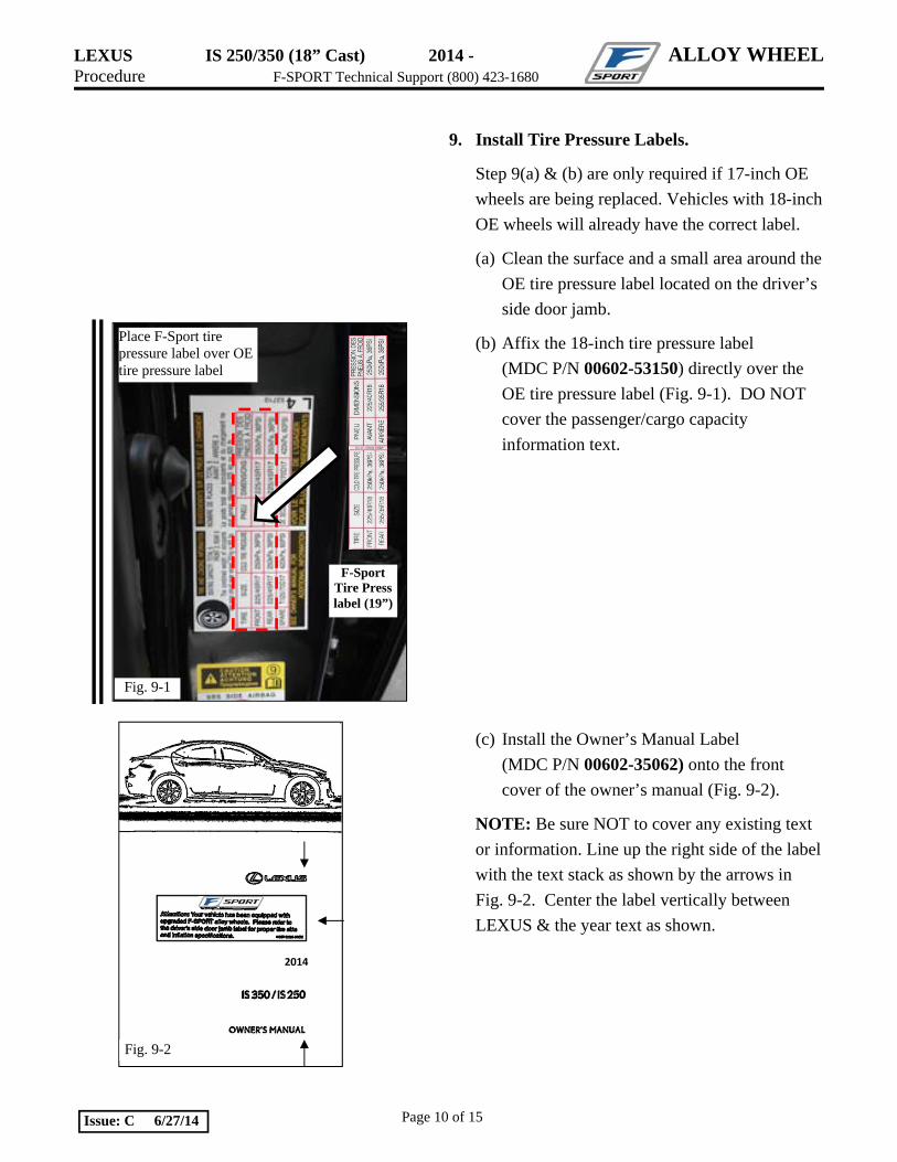
(c) Install the Owner’s Manual Label
(MDC P/N 00602-35062) onto the front
cover of the owner’s manual (Fig. 9-2).
NOTE: Be sure NOT to cover any existing text
or information. Line up the right side of the label
with the text stack as shown by the arrows in
Fig. 9-2. Center the label vertically between
LEXUS & the year text as shown.
Fig. 9-2
2014
F-Sport Tire Press label (19”)
Fig. 9-1
Place F-Sport tire pressure label over OE tire pressure label

LEXUS IS 250/350 (18” Cast) 2014 - ALLOY WHEEL Procedure F-SPORT Technical Support (800) 423-1680
Page 11 of 15 Issue: C 6/27/14
10. Register the TPMS Transmitter IDs.
Perform ONLY when replacing the tire pressure monitoring sensors.
Go to Step 10 if reusing the same 20-degree sensors.
(a) Complete this section after all four wheels
have been installed.
(b) Connect the Techstream to DLC3.
(c) Turn the ignition switch to the ON position
(do not start the vehicle), then turn the
Techstream ON.
(d) Start the Techstream application by clicking
on the shortcut located on the Desktop.
(e) Click “Connect to Vehicle” button (Fig. 10-
1).
(f) Confirm that the information displayed on
the Vehicle Connection Wizard is correct. If
not, make the appropriate selections from the
drop down menus, then click “Next” (Fig.
10-2).
Fig. 10-2
Fig. 10-1

LEXUS IS 250/350 (18” Cast) 2014 - ALLOY WHEEL Procedure F-SPORT Technical Support (800) 423-1680
Page 12 of 15 Issue: C 6/27/14
(g) Select “Tire Pressure Monitor” then click
the green arrow located on the bottom right
(Fig. 10-3).
(h) Select “UTILITY” to begin input of new
TPMS ID codes (Fig. 10-4).
(i) Select “ID Registration” then click the
green arrow located at the bottom right
corner (Fig. 10-5).
Fig. 10-4
Fig. 10-3
Fig. 10-5
LEXUS IS 250/350 (18” Cast) 2014 - ALLOY WHEEL Procedure F-SPORT Technical Support (800) 423-1680
Page 13 of 15 Issue: C 6/27/14
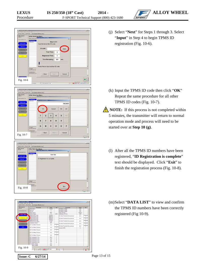
(j) Select “Next” for Steps 1 through 3. Select
“Input” in Step 4 to begin TPMS ID
registration (Fig. 10-6).
(k) Input the TPMS ID code then click “OK”
Repeat the same procedure for all other
TPMS ID codes (Fig. 10-7).
NOTE: If this process is not completed within
5 minutes, the transmitter will return to normal
operation mode and process will need to be
started over at Step 10 (g).
(l) After all the TPMS ID numbers have been
registered, “ID Registration is complete”
text should be displayed. Click “Exit” to
finish the registration process (Fig. 10-8).
(m) Select “DATA LIST” to view and confirm
the TPMS ID numbers have been correctly
registered (Fig 10-9).
Fig. 10-6
Fig. 10-7
Fig. 10-8
Fig. 10-9

LEXUS IS 250/350 (18” Cast) 2014 - ALLOY WHEEL Procedure F-SPORT Technical Support (800) 423-1680
Page 14 of 15 Issue: C 6/27/14
11. Breakdown of the OE Wheel & Tire Assembly.
For PPO (a) Sort the product properly according to local
regulations.
(b) Take-off tires get picked up by Dealer Tire.
(c) Take-off wheels get salvaged according to
local regulations.
For DIO
(d) Sort the product properly according to local
regulations.
12. Pre Delivery Service.
(a) Perform the PDS procedure for the Tire
Pressure Warning System Initialization (refer
to the current service bulletin [i.e. L-SB-
0026-13] or the Owner’s Manual).

LEXUS IS250/350 (18” Cast) 2014 - ALLOY WHEEL F-SPORT Technical Support (800) 423-1680 Checklist: these points MUST be checked to ensure a quality installation.
Check: Look For:
Page 15 of 15 Issue: C 6/27/14
Accessory Function Checks
Inspect lug nuts.
Lug nut tightness.
Lug nut tool placement.
Tire Pressure Labels
Correct Tire Pressure
Tire Identification Numbers
Center Caps
Wheel Locks
Vehicle Appearance Check
After accessory installation and removal of protective cover(s), perform a visual inspection.
Ensure five lug nuts are installed on each wheel.
Ensure the lug nut torque is 103N·m (76 ft-lbf).
Ensure the lug nut tool is in the appropriate location in the vehicle.
Ensure Tire Pressure Label and Owner’s Manual Labels are in place.
Ensure the tire pressure is set to the value specified on the F-Sport Tire Pressure Label. PPO: Ensure all 4 accessory Tire Identification Numbers are recorded with the Vehicle Identification Number. Refer to CAD PPO Bulletin as needed. DIO: Provide the tire information to your tire vendor as required by law. Verify center caps are securely in place on all 4 wheels. Also verify that they are in the correct orientation. Verify the wheel lock key tool is in the appropriate location in the vehicle and the paperwork is placed into the vehicle glove compartment.
Ensure no damage (including scuffs and scratches) was caused during the installation process. (For PPO installations, refer to TMS Accessory Quality Shipping Standard.