Embed Size (px)
Citation preview

© 2020 Industries Inc.
Litho U.S.A.Page 1
Corp. 1112-L2
LGH/LCH20 / 25 / 30 TON71 / 88 / 105 kWRevised 05/2020
LGH/LCH SERIES
The LGH/LCH242H, 300H, 360H (20, 25 and 30 ton) units
are configured to order units (CTO) with a wide selection of
factory-installed options. The LGH gas/electric packaged
rooftop units are available in 260,000 Btuh, 360,000 Btuh
and 480,000 Btuh (76.2 kW, 105.5 and 137.7 kW) heating
inputs. Gas heat sections are designed with aluminized
steel tube heat exchangers. The LCH cooling packaged
rooftop units are equipped with the same cooling sections
as the LGH units. Units utilize four compressors.
Units may contain a supply air blower equipped with a vari
able frequency drive A96 (VFD) which varies supply air
CFM.
Optional electric heat is factory-or field-installed in LCH
units. Electric heat operates in single or multiple stages de
pending on the kW input size. 30kW through 120kW heat
sections are available.
Units are also designed for R-410A refrigerant. See unit
nameplate for refrigerant type and charge. Service equip
ment for R-410A units must be rated for R-410A refriger
ant.
Units are designed to accept any of several different ener
gy management thermostat control systems with mini
mum field wiring. Factory or field provided control options
connect to the Unit Controller through SmartwireTM con
nectors. When "plugged in" the controls become an inte
gral part of the unit wiring.
Information contained in this manual is intended for use by
qualified service technicians only. All specifications are
subject to change. Procedures outlined in this manual are
presented as a recommendation only and do not super
sede or replace local or state codes.
If the unit must be lifted for service, rig unit by attaching four
cables to the holes located in the unit base rail (two holes at
each corner). Refer to the installation instructions for the
proper rigging technique.
LGH360
LGH360
WARNINGImproper installation, adjustment, alteration, serviceor maintenance can cause property damage, personal injury or loss of life. Installation and service mustbe performed by a qualified installer or service agency.
WARNINGElectric shock hazard. Can cause injuryor death. Before attempting to performany service or maintenance, turn theelectrical power to unit OFF at disconnect switch(es). Unit may have multiplepower supplies.
CAUTIONDanger of sharp metallic edges. Can cause injury.Take care when servicing unit to avoid accidentalcontact with sharp edges.

Page 2
TABLE OF CONTENTS
Introduction Page 1. . . . . . . . . . . . . . . . . . . . . . . . . . .
Options / Accessories Page 3. . . . . . . . . . . . . . . . . .
Specifications Page 7. . . . . . . . . . . . . . . . . . . . . . . . . .
High Altitude Page 9. . . . . . . . . . . . . . . . . . . . . . . . . . .
Blower Data Page 10. . . . . . . . . . . . . . . . . . . . . . . . . .
Electrical Data / Electric Heat Data Page 14. . . . . .
Parts Arrangement Page 25. . . . . . . . . . . . . . . . . . . .
I- UNIT COMPONENTS Page 27. . . . . . . . . . . . . . . . .
Control Box Components Page 26. . . . . . . . . . . .
Cooling Components Page 31. . . . . . . . . . . . . . . . . .
Blower Compartment Page 34. . . . . . . . . . . . . . . . . .
Gas Heat Components Page 38. . . . . . . . . . . . . . . .
Electric Heat Components Page 44. . . . . . . . . . . . .
II- PLACEMENT AND INSTALLATION Page 48. . . .
III- START UP Page 48. . . . . . . . . . . . . . . . . . . . . . . . . .
Preliminary Checks Page 48. . . . . . . . . . . . . . . . . . .
Cooling Start Up Page 48. . . . . . . . . . . . . . . . . . . . . .
Charging Page 49. . . . . . . . . . . . . . . . . . . . . . . . . . . .
Heating Start Up Page 62. . . . . . . . . . . . . . . . . . . . . .
Safety or Emergency Shutdown Page 63. . . . . . . .
IV-SYSTEM SERVICE CHECKS Page 63. . . . . . . . . . .
Heating System Service Checks Page 63. . . . . . . .
Cooling System Service Checks Page 66. . . . . . . .
V-MAINTENANCE Page 66. . . . . . . . . . . . . . . . . . . . . . .
Filters Page 66. . . . . . . . . . . . . . . . . . . . . . . . . . . . . . .
Lubrication Page 66. . . . . . . . . . . . . . . . . . . . . . . . . .
Supply Air Blower Wheel Page 66. . . . . . . . . . . . . .
Evaporator Coil Page 66. . . . . . . . . . . . . . . . . . . . . . .
Condenser Coil Page 66. . . . . . . . . . . . . . . . . . . . . . .
Electrical Page 66. . . . . . . . . . . . . . . . . . . . . . . . . . . .
VI-ACCESSORIES Page 66. . . . . . . . . . . . . . . . . . . . . . .
Roof Mounting Frames Page 66. . . . . . . . . . . . . . . .
Control Systems Page 67. . . . . . . . . . . . . . . . . . . . . .
Transitions Page 67. . . . . . . . . . . . . . . . . . . . . . . . . . .
Supply and Return Diffusers Page 67. . . . . . . . . . .
Outdoor Air Dampers Page 68. . . . . . . . . . . . . . . . .
Economizers Page 68. . . . . . . . . . . . . . . . . . . . . . . . .
Gravity Exhaust Dampers Page 69. . . . . . . . . . . . . .
LP / Propane Kit Page 69. . . . . . . . . . . . . . . . . . . . . .
Power Exhaust Fans Page 69. . . . . . . . . . . . . . . . . .
Smoke Detectors Page 69. . . . . . . . . . . . . . . . . . . .
Blower Proving Switch Page 70. . . . . . . . . . . . . . . . .
Dirty Filter Switch Page 70. . . . . . . . . . . . . . . . . . . . .
Optional Cold Weather Kit Page 70. . . . . . . . . . . . .
Indoor Air Quality Sensor Page 70. . . . . . . . . . . . . .
Supply Air VFD Page 70. . . . . . . . . . . . . . . . . . . . . . .
Drain Pan Overflow Switch Page 71. . . . . . . . . . . . .
VII-DIAGRAMS / OPERATION SEQUENCE Page 72.
Page 3
OPTIONS / ACCESSORIES
Item Description Model Number
Catalog Number
Unit Model No.242 300 360
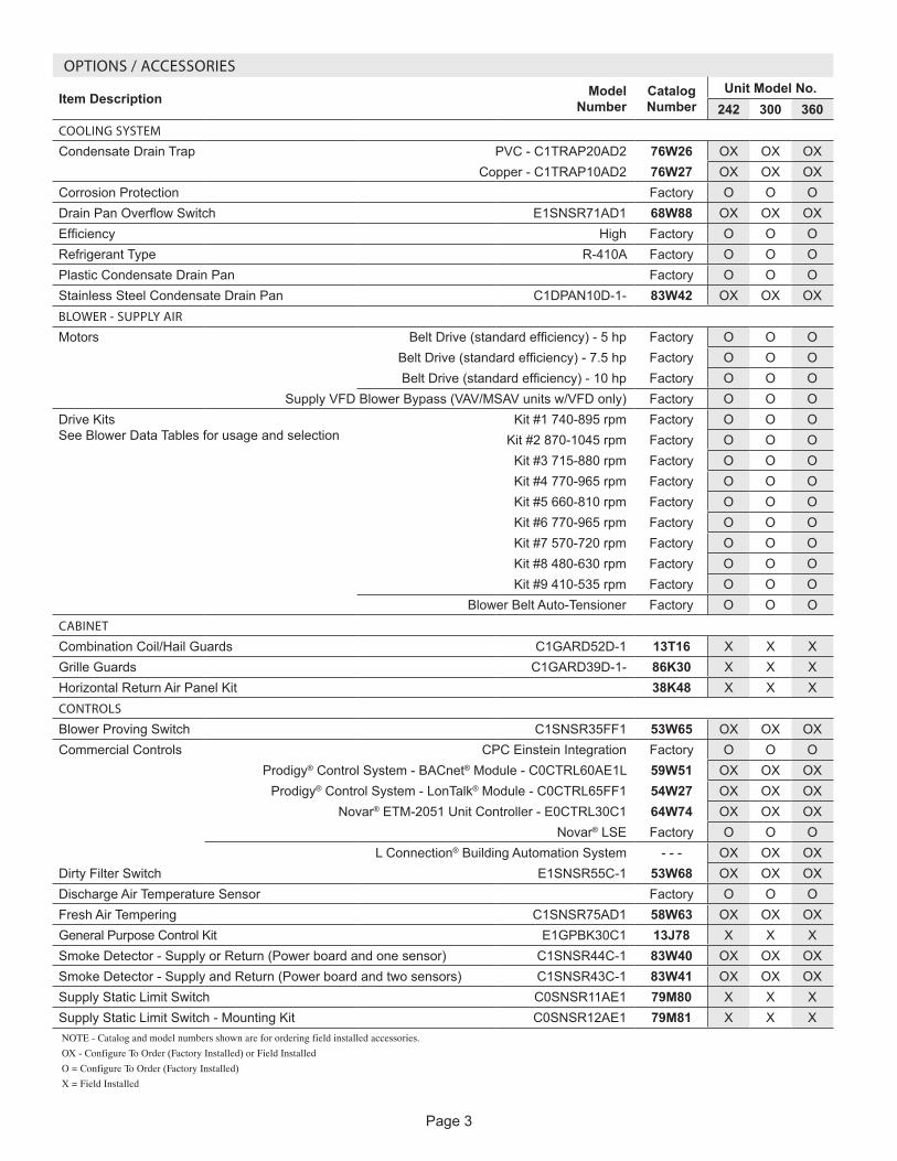
COOLING SYSTEM
Condensate Drain Trap PVC - C1TRAP20AD2 76W26 OX OX OXCopper - C1TRAP10AD2 76W27 OX OX OX
Corrosion Protection Factory O O ODrain Pan Overflow Switch E1SNSR71AD1 68W88 OX OX OXEfficiency High Factory O O ORefrigerant Type R-410A Factory O O OPlastic Condensate Drain Pan Factory O O OStainless Steel Condensate Drain Pan C1DPAN10D-1- 83W42 OX OX OXBLOWER - SUPPLY AIR
Motors Belt Drive (standard efficiency) - 5 hp Factory O O OBelt Drive (standard efficiency) - 7.5 hp Factory O O OBelt Drive (standard efficiency) - 10 hp Factory O O O
Supply VFD Blower Bypass (VAV/MSAV units w/VFD only) Factory O O ODrive Kits See Blower Data Tables for usage and selection
Kit #1 740-895 rpm Factory O O OKit #2 870-1045 rpm Factory O O OKit #3 715-880 rpm Factory O O OKit #4 770-965 rpm Factory O O OKit #5 660-810 rpm Factory O O OKit #6 770-965 rpm Factory O O OKit #7 570-720 rpm Factory O O OKit #8 480-630 rpm Factory O O OKit #9 410-535 rpm Factory O O O
Blower Belt Auto-Tensioner Factory O O OCABINET
Combination Coil/Hail Guards C1GARD52D-1 13T16 X X XGrille Guards C1GARD39D-1- 86K30 X X XHorizontal Return Air Panel Kit 38K48 X X XCONTROLS
Blower Proving Switch C1SNSR35FF1 53W65 OX OX OXCommercial Controls CPC Einstein Integration Factory O O O
Prodigy® Control System - BACnet® Module - C0CTRL60AE1L 59W51 OX OX OXProdigy® Control System - LonTalk® Module - C0CTRL65FF1 54W27 OX OX OX
Novar® ETM-2051 Unit Controller - E0CTRL30C1 64W74 OX OX OXNovar® LSE Factory O O O
L Connection® Building Automation System - - - OX OX OXDirty Filter Switch E1SNSR55C-1 53W68 OX OX OXDischarge Air Temperature Sensor Factory O O OFresh Air Tempering C1SNSR75AD1 58W63 OX OX OXGeneral Purpose Control Kit E1GPBK30C1 13J78 X X XSmoke Detector - Supply or Return (Power board and one sensor) C1SNSR44C-1 83W40 OX OX OXSmoke Detector - Supply and Return (Power board and two sensors) C1SNSR43C-1 83W41 OX OX OXSupply Static Limit Switch C0SNSR11AE1 79M80 X X XSupply Static Limit Switch - Mounting Kit C0SNSR12AE1 79M81 X X XNOTE - Catalog and model numbers shown are for ordering field installed accessories.
OX - Configure To Order (Factory Installed) or Field Installed
O = Configure To Order (Factory Installed)
X = Field Installed

Page 4
OPTIONS / ACCESSORIES
Item Description Model Number
Catalog Number
Unit Model No.242 300 360
INDOOR AIR QUALITYAir FiltersHealthy Climate® High Efficiency Air Filters 20 x 20 x 2 - order 12 per unit
MERV 8 - C1FLTR15D-1- 54W21 OX OX OXMERV 13 - C1FLTR40D-1- 52W39 OX OX OX
Replaceable Media Filter with Metal Mesh Frame (includes Non-Pleated Filter Media) 20 x 20 x 2- order 12 per unit
C1FLTR30D-1- 44N60 X X X
Indoor Air Quality (CO2) SensorsSensor - Wall-mount, off-white plastic cover with LCD display C0SNSR50AE1L 77N39 X X XSensor - Wall-mount, off-white plastic cover, no display C0SNSR52AE1L 87N53 X X XSensor - Black plastic case with LCD display, rated for plenum mounting C0SNSR51AE1L 87N52 X X XSensor - Wall-mount, black plastic case, no display, rated for plenum mounting
C0MISC19AE1 87N54 X X X
CO2 Sensor Duct Mounting Kit - for downflow applications C0MISC19AE1- 85L43 X X XAspiration Box - for duct mounting non-plenum rated CO2 sensors (87N53 or 77N39)
C0MISC16AE1- 90N43 X X X
UVC Germicidal Light Kit1 Healthy Climate® UVC Light Kit (110/230v-1ph) Factory O O OELECTRICALVoltage 60 hz 208/230V - 3 phase Factory O O O
460V - 3 phase Factory O O O575V - 3 phase Factory O O O
HACR Circuit Breakers Factory O O ODisconnect Switch 80 amp 54W85 OX OX OX
150 amp 54W86 OX OX OX250 amp 54W87 OX OX OX
GFI Service Outlets
15 amp non-powered, field-wired (208/230V, 460V) LTAGFIK10/15 74M70 OX OX OX15 amp factory-wired and powered (208/230V, 460V, 575V) Factory O O O
20 amp non-powered, field-wired (575V only) C1GFCI20FF1 67E01 OX OX OXWeatherproof Cover for GFI C1GFCI99FF1 10C89 X X XPhase/Voltage Detection Factory O O OELECTRIC HEAT30 kW 208/230V-3ph - C1EH0300C21Y 53W92 OX OX OX
460V-3ph - C1EH0300C21G 53W94 OX OX OX575V-3ph - C1EH0300C21J 53W95 OX OX OX
45 kW 208/230V-3ph - C1EH0450C21Y 54W00 OX OX OX460V-3ph - C1EH0450C21G 54W02 OX OX OX575V-3ph - C1EH0450C21J 54W03 OX OX OX
60 kW 208/230V-3ph - C1EH0600C21Y 54W08 OX OX OX460V-3ph - C1EH0600C21G 54W10 OX OX OX575V-3ph - C1EH0600C21J 54W11 OX OX OX
90 kW 208/230V-3ph - C1EH0900C21Y 54W12 OX OX OX460V-3ph - C1EH0900C21G 54W14 OX OX OX575V-3ph - C1EH0900C21J 54W15 OX OX OX
120 kW 208/230V-3ph - E1EH1200D-1Y 73W98 OX OX OX460V-3ph - E1EH1200D-1G 73W99 OX OX OX575V-3ph - E1EH1200D-1J 74W00 OX OX OX
SCR (Silicon Controlled Rectifier) Electric Heat ControlNOTE - The SCR option is not available with 60 kW, 90 kW (208/230V) and 120 kW (208/230V, 460V, 575V) electric heat models.
Factory O O O
Thermostat (required) 45N59 X X XDuct Sensor (required) 45N60 X X X1 Lamps operate on 110/230V, single phase power supply. Step-down transformer is furnished with lamps when used with 460V and 575V rooftop units.
NOTE - Catalog and model numbers shown are for ordering field installed accessories.
OX - Configure To Order (Factory Installed) or Field Installed
O = Configure To Order (Factory Installed)
X = Field Installed
Page 5
OPTIONS / ACCESSORIES
Item Description Model Number
Catalog Number
Unit Model No.242 300 360
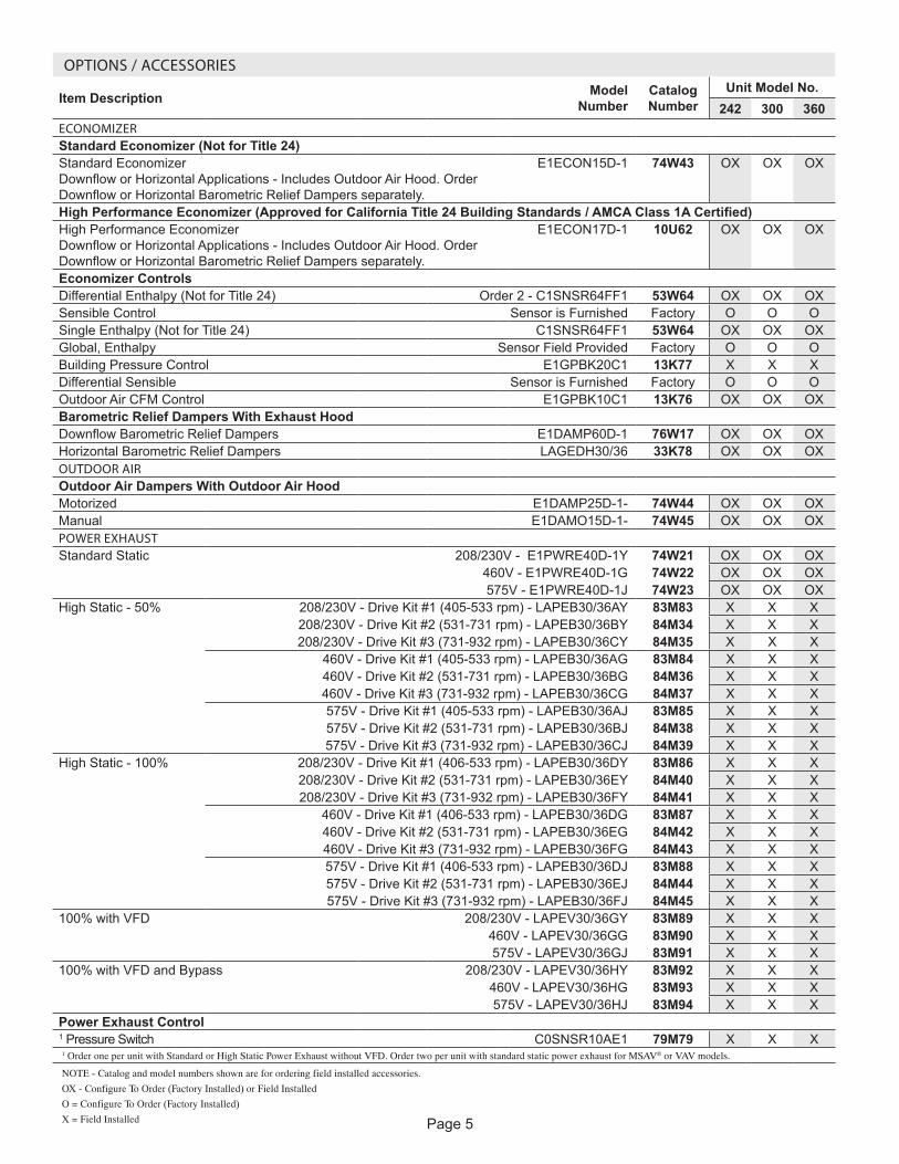
ECONOMIZERStandard Economizer (Not for Title 24)Standard Economizer Downflow or Horizontal Applications - Includes Outdoor Air Hood. Order Downflow or Horizontal Barometric Relief Dampers separately.
E1ECON15D-1 74W43 OX OX OX
High Performance Economizer (Approved for California Title 24 Building Standards / AMCA Class 1A Certified)High Performance Economizer Downflow or Horizontal Applications - Includes Outdoor Air Hood. Order Downflow or Horizontal Barometric Relief Dampers separately.
E1ECON17D-1 10U62 OX OX OX
Economizer ControlsDifferential Enthalpy (Not for Title 24) Order 2 - C1SNSR64FF1 53W64 OX OX OXSensible Control Sensor is Furnished Factory O O OSingle Enthalpy (Not for Title 24) C1SNSR64FF1 53W64 OX OX OXGlobal, Enthalpy Sensor Field Provided Factory O O OBuilding Pressure Control E1GPBK20C1 13K77 X X XDifferential Sensible Sensor is Furnished Factory O O OOutdoor Air CFM Control E1GPBK10C1 13K76 OX OX OXBarometric Relief Dampers With Exhaust HoodDownflow Barometric Relief Dampers E1DAMP60D-1 76W17 OX OX OXHorizontal Barometric Relief Dampers LAGEDH30/36 33K78 OX OX OXOUTDOOR AIROutdoor Air Dampers With Outdoor Air HoodMotorized E1DAMP25D-1- 74W44 OX OX OXManual E1DAMO15D-1- 74W45 OX OX OXPOWER EXHAUSTStandard Static 208/230V - E1PWRE40D-1Y 74W21 OX OX OX
460V - E1PWRE40D-1G 74W22 OX OX OX575V - E1PWRE40D-1J 74W23 OX OX OX
High Static - 50% 208/230V - Drive Kit #1 (405-533 rpm) - LAPEB30/36AY 83M83 X X X208/230V - Drive Kit #2 (531-731 rpm) - LAPEB30/36BY 84M34 X X X208/230V - Drive Kit #3 (731-932 rpm) - LAPEB30/36CY 84M35 X X X
460V - Drive Kit #1 (405-533 rpm) - LAPEB30/36AG 83M84 X X X460V - Drive Kit #2 (531-731 rpm) - LAPEB30/36BG 84M36 X X X460V - Drive Kit #3 (731-932 rpm) - LAPEB30/36CG 84M37 X X X575V - Drive Kit #1 (405-533 rpm) - LAPEB30/36AJ 83M85 X X X575V - Drive Kit #2 (531-731 rpm) - LAPEB30/36BJ 84M38 X X X575V - Drive Kit #3 (731-932 rpm) - LAPEB30/36CJ 84M39 X X X
High Static - 100% 208/230V - Drive Kit #1 (406-533 rpm) - LAPEB30/36DY 83M86 X X X208/230V - Drive Kit #2 (531-731 rpm) - LAPEB30/36EY 84M40 X X X208/230V - Drive Kit #3 (731-932 rpm) - LAPEB30/36FY 84M41 X X X
460V - Drive Kit #1 (406-533 rpm) - LAPEB30/36DG 83M87 X X X460V - Drive Kit #2 (531-731 rpm) - LAPEB30/36EG 84M42 X X X460V - Drive Kit #3 (731-932 rpm) - LAPEB30/36FG 84M43 X X X575V - Drive Kit #1 (406-533 rpm) - LAPEB30/36DJ 83M88 X X X575V - Drive Kit #2 (531-731 rpm) - LAPEB30/36EJ 84M44 X X X575V - Drive Kit #3 (731-932 rpm) - LAPEB30/36FJ 84M45 X X X
100% with VFD 208/230V - LAPEV30/36GY 83M89 X X X460V - LAPEV30/36GG 83M90 X X X575V - LAPEV30/36GJ 83M91 X X X
100% with VFD and Bypass 208/230V - LAPEV30/36HY 83M92 X X X460V - LAPEV30/36HG 83M93 X X X575V - LAPEV30/36HJ 83M94 X X X
Power Exhaust Control1 Pressure Switch C0SNSR10AE1 79M79 X X X1 Order one per unit with Standard or High Static Power Exhaust without VFD. Order two per unit with standard static power exhaust for MSAV® or VAV models.
NOTE - Catalog and model numbers shown are for ordering field installed accessories.
OX - Configure To Order (Factory Installed) or Field Installed
O = Configure To Order (Factory Installed)
X = Field Installed
Page 6
OPTIONS / ACCESSORIES
Item Description Model Number
Catalog Number
Unit Model No.242 300 360
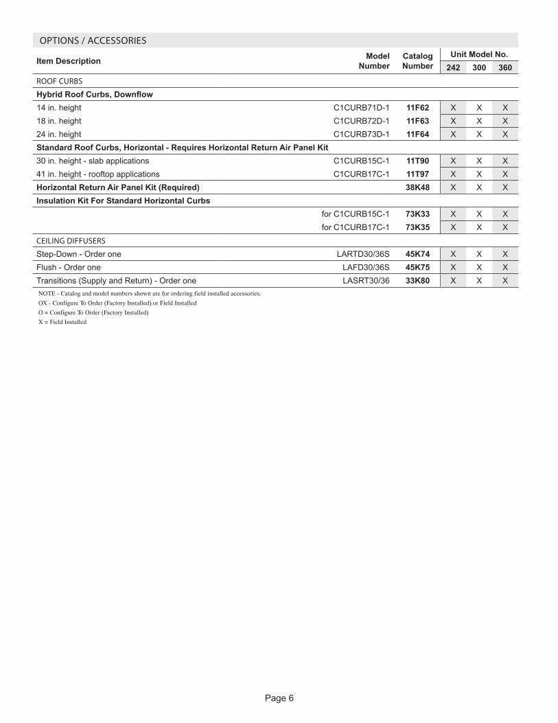
ROOF CURBS
Hybrid Roof Curbs, Downflow14 in. height C1CURB71D-1 11F62 X X X18 in. height C1CURB72D-1 11F63 X X X24 in. height C1CURB73D-1 11F64 X X XStandard Roof Curbs, Horizontal - Requires Horizontal Return Air Panel Kit30 in. height - slab applications C1CURB15C-1 11T90 X X X41 in. height - rooftop applications C1CURB17C-1 11T97 X X XHorizontal Return Air Panel Kit (Required) 38K48 X X XInsulation Kit For Standard Horizontal Curbs
for C1CURB15C-1 73K33 X X Xfor C1CURB17C-1 73K35 X X X
CEILING DIFFUSERS
Step-Down - Order one LARTD30/36S 45K74 X X XFlush - Order one LAFD30/36S 45K75 X X XTransitions (Supply and Return) - Order one LASRT30/36 33K80 X X XNOTE - Catalog and model numbers shown are for ordering field installed accessories.
OX - Configure To Order (Factory Installed) or Field Installed
O = Configure To Order (Factory Installed)
X = Field Installed

Page 7
SPECIFICATIONS LGH, LCHGeneral Data Nominal Tonnage 20 Ton 25 Ton 25 Ton 25 Ton
Model Number 242H4V 300H4B 300H4V 300H4MEfficiency Type High High High High
Blower Type Variable Air Volume (VAV)
Constant Air Volume (CAV)
Variable Air Volume (VAV)
MSAV® (Multi-Stage Air
Volume)Cooling Performance
Gross Cooling Capacity - Btuh 244,000 310,000 310,000 310,000Net Cooling Capacity - Btuh 1 238,000 2 300,000 2 300,000 2 300,000
AHRI Rated Air Flow - cfm 6800 8100 8100 8100Total Unit Power - kW 19 25.4 25.8 25.8
EER (Btuh/Watt) 1 12.5 2 11.8 2 11.6 2 11.6IEER (Btuh/Watt) 1 15.5 2 12.5 2 14.3 2 14.4Refrigerant Type R-410A R-410A R-410A R-410A
Refrigerant Charge
Circuit 1 8 lbs. 0 oz. 9 lbs. 4 oz. 8 lbs. 0 oz. 8 lbs. 0 oz.Circuit 2 8 lbs. 0 oz. 9 lbs. 0 oz. 8 lbs. 0 oz. 8 lbs. 0 oz.Circuit 3 8 lbs. 8 oz. 8 lbs. 12 oz. 8 lbs. 0 oz. 8 lbs. 0 oz.Circuit 4 8 lbs. 8 oz. 8 lbs. 8 oz. 8 lbs. 8 oz. 8 lbs. 8 oz.
Electric Heat Available 30-45-60-90-120 kWCompressor Type (number) Scroll (4) Scroll (4) Scroll (4) Scroll (4)Outdoor Coils
Net face area (total) - sq. ft. 68.3 68.3 68.3 68.3Number of rows 1 1 1 1
Fins per inch 23 23 23 23Outdoor Coil Fans
Motor - (No.) horsepower (6) 1/3 (6) 1/3 (6) 1/3 (6) 1/3Motor rpm 1075 1075 1075 1075
Total Motor watts 2500 2500 2500 2500Diameter - (No.) in. (6) 24 (6) 24 (6) 24 (6) 24
Number of blades 3 3 3 3Total Air volume - cfm 21,500 21,500 21,500 21,500
Indoor Coils Net face area (total) - sq. ft. 31.40 31.40 31.40 31.40Tube diameter - in. 3/8 3/8 3/8 3/8
Number of rows 4 4 4 4Fins per inch 14 14 14 14
Drain connection - No. and size (1) 1 in. NPT (1) 1 in. NPT (1) 1 in. NPT (1) 1 in. NPTExpansion device type Balance port TXV, removable head
3 Indoor Blower and Kit Selection
Nominal motor output 5 hp, 7.5 hp, 10 hpMaximum usable motor
output (US Only)5.75 hp,
8.63 hp, 11.5 hpMotor - Kit kit number 5 hp
Kit 5 660-810 rpm Kit 6 770-965 rpm Kit 7 570-720 rpm Kit 8 480-630 rpm Kit 9 410-535 rpm
7.5 hp Kit 3 715-880 rpm Kit 4 770-965 rpm
10 hp Kit 1 740-895 rpm Kit 2 870-1045 rpm
Blower wheel nom. D x W - in. (2) 18 x 15 (2) 18 x 15 (2) 18 x 15 (2) 18 x 15Filters Type of filter Fiberglass, disposable
Number and size - in. (12) 20 x 20 x 2Electrical characteristics 208/230V, 460V or 575V - 60 hertz - 3 phaseNOTE - Net capacity includes evaporator blower motor heat deduction. Gross capacity does not include evaporator blower motor heat deduction.1 AHRI Certified to AHRI Standard 340/360; 95°F outdoor air temperature and 80°F db/67°F wb entering evaporator air; minimum external duct static pressure.2 Tested at conditions included in with AHRI Standard 340/360.3 Using total air volume and system static pressure requirements determine from blower performance tables rpm and motor output required. Maximum usable output of motors furnished
are shown. In Canada, nominal motor output is also maximum usable motor output. If motors of comparable output are used, be sure to keep within the service factor limitations outlined on the motor nameplate.

Page 8
SPECIFICATIONS LGH, LCHGeneral Data Nominal Tonnage 30 Ton 30 Ton 30 Ton
Model Number 360H4B 360H4V 360H4MEfficiency Type High High High
Blower Type Constant Air Volume (CAV)
Variable Air Volume (VAV)
MSAV® (Multi-Stage Air Volume)
Cooling Performance
Gross Cooling Capacity - Btuh 370,000 370,000 370,0001 Net Cooling Capacity - Btuh 354,000 350,000 350,000
AHRI Rated Air Flow - cfm 9600 8600 8600Total Unit Power - kW 32.8 32.4 32.4
1 EER (Btuh/Watt) 10.8 10.8 10.81 IEER (Btuh/Watt) 11.6 13.5 14.0
Refrigerant Type R-410A R-410A R-410ARefrigerant Charge
Circuit 1 9 lbs. 0 oz. 8 lbs. 0 oz. 8 lbs. 0 oz.Circuit 2 8 lbs. 0 oz. 8 lbs. 0 oz. 8 lbs. 0 oz.Circuit 3 9 lbs. 0 oz. 8 lbs. 0 oz. 8 lbs. 0 oz.Circuit 4 7 lbs. 8 oz. 8 lbs. 0 oz. 8 lbs. 0 oz.
Electric Heat Available - 30-45-60-90-120 kWCompressor Type (number) Scroll (4) Scroll (4) Scroll (4)Outdoor Coils
Net face area (total) - sq. ft. 68.3 68.3 68.3Number of rows 1 1 1
Fins per inch 23 23 23Outdoor Coil Fans
Motor - (No.) horsepower (6) 1/3 (6) 1/3 (6) 1/3Motor rpm 1075 1075 1075
Total Motor watts 2500 2500 2500Diameter - (No.) in. (6) 24 (6) 24 (6) 24
Number of blades 3 3 3Total Air volume - cfm 21,500 21,500 21,500
Indoor Coils Net face area (total) - sq. ft. 31.40 31.40 31.40Tube diameter - in. 3/8 3/8 3/8
Number of rows 4 4 4Fins per inch 14 14 14
Drain connection - No. and size (1) 1 in. NPT (1) 1 in. NPT (1) 1 in. NPTExpansion device type Balance port TXV, removable head
3 Indoor Blower and Kit Selection
Nominal motor output 5 hp, 7.5 hp, 10 hpMaximum usable motor
output (US Only)5.75 hp, 8.63 hp, 11.5 hp
Motor - Kit kit number 5 hp Kit 5 660-810 rpm Kit 6 770-965 rpm Kit 7 570-720 rpm Kit 8 480-630 rpm Kit 9 410-535 rpm
7.5 hp Kit 3 715-880 rpm Kit 4 770-965 rpm
10 hp Kit 1 740-895 rpm Kit 2 870-1045 rpm
Blower wheel nom. D x W - in. (2) 18 x 15 (2) 18 x 15 (2) 18 x 15Filters Type of filter Fiberglass, disposable
Number and size - in. (12) 20 x 20 x 2Electrical characteristics 208/230V, 460V or 575V - 60 hertz - 3 phaseNOTE - Net capacity includes evaporator blower motor heat deduction. Gross capacity does not include evaporator blower motor heat deduction.1 AHRI Certified to AHRI Standard 340/360; 95°F outdoor air temperature and 80°F db/67°F wb entering evaporator air; minimum external duct static pressure.3 Using total air volume and system static pressure requirements determine from blower performance tables rpm and motor output required. Maximum usable output of motors furnished
are shown. In Canada, nominal motor output is also maximum usable motor output. If motors of comparable output are used, be sure to keep within the service factor limitations outlined on the motor nameplate.
Page 9
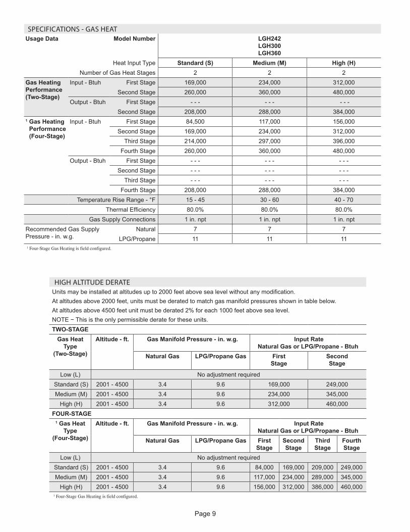
SPECIFICATIONS - GAS HEATUsage Data Model Number LGH242
LGH300 LGH360
Heat Input Type Standard (S) Medium (M) High (H)Number of Gas Heat Stages 2 2 2
Gas Heating Performance (Two-Stage)
Input - Btuh First Stage 169,000 234,000 312,000Second Stage 260,000 360,000 480,000
Output - Btuh First Stage - - - - - - - - -Second Stage 208,000 288,000 384,000
1 Gas Heating Performance (Four-Stage)
Input - Btuh First Stage 84,500 117,000 156,000Second Stage 169,000 234,000 312,000
Third Stage 214,000 297,000 396,000Fourth Stage 260,000 360,000 480,000
Output - Btuh First Stage - - - - - - - - -Second Stage - - - - - - - - -
Third Stage - - - - - - - - -Fourth Stage 208,000 288,000 384,000
Temperature Rise Range - °F 15 - 45 30 - 60 40 - 70Thermal Efficiency 80.0% 80.0% 80.0%
Gas Supply Connections 1 in. npt 1 in. npt 1 in. nptRecommended Gas Supply Pressure - in. w.g.
Natural 7 7 7LPG/Propane 11 11 11
1 Four-Stage Gas Heating is field configured.
HIGH ALTITUDE DERATE Units may be installed at altitudes up to 2000 feet above sea level without any modification.At altitudes above 2000 feet, units must be derated to match gas manifold pressures shown in table below.At altitudes above 4500 feet unit must be derated 2% for each 1000 feet above sea level.NOTE − This is the only permissible derate for these units.TWO-STAGE
Gas Heat Type
(Two-Stage)
Altitude - ft. Gas Manifold Pressure - in. w.g. Input Rate Natural Gas or LPG/Propane - Btuh
Natural Gas LPG/Propane Gas First Stage
Second Stage
Low (L) No adjustment required Standard (S) 2001 - 4500 3.4 9.6 169,000 249,000 Medium (M) 2001 - 4500 3.4 9.6 234,000 345,000
High (H) 2001 - 4500 3.4 9.6 312,000 460,000FOUR-STAGE
1 Gas Heat Type
(Four-Stage)
Altitude - ft. Gas Manifold Pressure - in. w.g. Input Rate Natural Gas or LPG/Propane - Btuh
Natural Gas LPG/Propane Gas First Stage
Second Stage
Third Stage
Fourth Stage
Low (L) No adjustment required Standard (S) 2001 - 4500 3.4 9.6 84,000 169,000 209,000 249,000 Medium (M) 2001 - 4500 3.4 9.6 117,000 234,000 289,000 345,000
High (H) 2001 - 4500 3.4 9.6 156,000 312,000 386,000 460,0001 Four-Stage Gas Heating is field configured.
Page 10
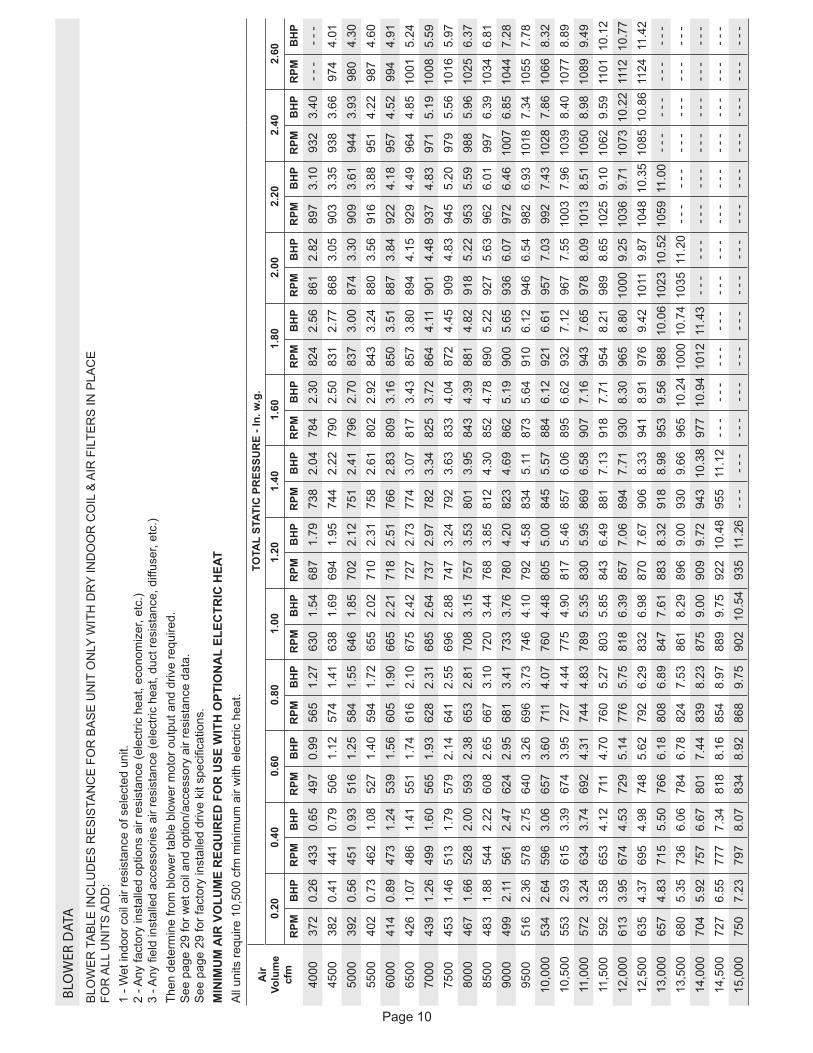
BLO
WER
DAT
A
BLO
WE
R T
AB
LE IN
CLU
DE
S R
ES
ISTA
NC
E F
OR
BA
SE
UN
IT O
NLY
WIT
H D
RY
IND
OO
R C
OIL
& A
IR F
ILTE
RS
IN P
LAC
E
FOR
ALL
UN
ITS
AD
D:
1 - W
et in
door
coi
l air
resi
stan
ce o
f sel
ecte
d un
it.
2 - A
ny fa
ctor
y in
stal
led
optio
ns a
ir re
sist
ance
(ele
ctric
hea
t, ec
onom
izer
, etc
.) 3
- Any
fiel
d in
stal
led
acce
ssor
ies
air r
esis
tanc
e (e
lect
ric h
eat,
duct
resi
stan
ce, d
iffus
er, e
tc.)
Then
det
erm
ine
from
blo
wer
tabl
e bl
ower
mot
or o
utpu
t and
driv
e re
quire
d.
See
pag
e 29
for w
et c
oil a
nd o
ptio
n/ac
cess
ory
air r
esis
tanc
e da
ta.
See
pag
e 29
for f
acto
ry in
stal
led
driv
e ki
t spe
cific
atio
ns.
MIN
IMU
M A
IR V
OLU
ME
REQ
UIR
ED F
OR
USE
WIT
H O
PTIO
NA
L EL
ECTR
IC H
EAT
All
units
requ
ire 1
0,50
0 cf
m m
inim
um a
ir w
ith e
lect
ric h
eat.
Air
Volu
me
cfm
TOTA
L ST
ATIC
PR
ESSU
RE
- In.
w.g
.0.
200.
400.
600.
801.
001.
201.
401.
601.
802.
002.
202.
402.
60
RPM
BH
PR
PMB
HP
RPM
BH
PR
PMB
HP
RPM
BH
PR
PMB
HP
RPM
BH
PR
PMB
HP
RPM
BH
PR
PMB
HP
RPM
BH
PR
PMB
HP
RPM
BH
P
4000
372
0.26
433
0.65
497
0.99
565
1.27
630
1.54
687
1.79
738
2.04
784
2.30
824
2.56
861
2.82
897
3.10
932
3.40
- - -
- - -
4500
382
0.41
441
0.79
506
1.12
574
1.41
638
1.69
694
1.95
744
2.22
790
2.50
831
2.77
868
3.05
903
3.35
938
3.66
974
4.01
5000
392
0.56
451
0.93
516
1.25
584
1.55
646
1.85
702
2.12
751
2.41
796
2.70
837
3.00
874
3.30
909
3.61
944
3.93
980
4.30
5500
402
0.73
462
1.08
527
1.40
594
1.72
655
2.02
710
2.31
758
2.61
802
2.92
843
3.24
880
3.56
916
3.88
951
4.22
987
4.60
6000
414
0.89
473
1.24
539
1.56
605
1.90
665
2.21
718
2.51
766
2.83
809
3.16
850
3.51
887
3.84
922
4.18
957
4.52
994
4.91
6500
426
1.07
486
1.41
551
1.74
616
2.10
675
2.42
727
2.73
774
3.07
817
3.43
857
3.80
894
4.15
929
4.49
964
4.85
1001
5.24
7000
439
1.26
499
1.60
565
1.93
628
2.31
685
2.64
737
2.97
782
3.34
825
3.72
864
4.11
901
4.48
937
4.83
971
5.19
1008
5.59
7500
453
1.46
513
1.79
579
2.14
641
2.55
696
2.88
747
3.24
792
3.63
833
4.04
872
4.45
909
4.83
945
5.20
979
5.56
1016
5.97
8000
467
1.66
528
2.00
593
2.38
653
2.81
708
3.15
757
3.53
801
3.95
843
4.39
881
4.82
918
5.22
953
5.59
988
5.96
1025
6.37
8500
483
1.88
544
2.22
608
2.65
667
3.10
720
3.44
768
3.85
812
4.30
852
4.78
890
5.22
927
5.63
962
6.01
997
6.39
1034
6.81
9000
499
2.11
561
2.47
624
2.95
681
3.41
733
3.76
780
4.20
823
4.69
862
5.19
900
5.65
936
6.07
972
6.46
1007
6.85
1044
7.28
9500
516
2.36
578
2.75
640
3.26
696
3.73
746
4.10
792
4.58
834
5.11
873
5.64
910
6.12
946
6.54
982
6.93
1018
7.34
1055
7.78
10,0
0053
42.
6459
63.
0665
73.
6071
14.
0776
04.
4880
55.
0084
55.
5788
46.
1292
16.
6195
77.
0399
27.
4310
287.
8610
668.
3210
,500
553
2.93
615
3.39
674
3.95
727
4.44
775
4.90
817
5.46
857
6.06
895
6.62
932
7.12
967
7.55
1003
7.96
1039
8.40
1077
8.89
11,0
0057
23.
2463
43.
7469
24.
3174
44.
8378
95.
3583
05.
9586
96.
5890
77.
1694
37.
6597
88.
0910
138.
5110
508.
9810
899.
4911
,500
592
3.58
653
4.12
711
4.70
760
5.27
803
5.85
843
6.49
881
7.13
918
7.71
954
8.21
989
8.65
1025
9.10
1062
9.59
1101
10.1
212
,000
613
3.95
674
4.53
729
5.14
776
5.75
818
6.39
857
7.06
894
7.71
930
8.30
965
8.80
1000
9.25
1036
9.71
1073
10.2
211
1210
.77
12,5
0063
54.
3769
54.
9874
85.
6279
26.
2983
26.
9887
07.
6790
68.
3394
18.
9197
69.
4210
119.
8710
4810
.35
1085
10.8
611
2411
.42
13,0
0065
74.
8371
55.
5076
66.
1880
86.
8984
77.
6188
38.
3291
88.
9895
39.
5698
810
.06
1023
10.5
210
5911
.00
- - -
- - -
- - -
- - -
13,5
0068
05.
3573
66.
0678
46.
7882
47.
5386
18.
2989
69.
0093
09.
6696
510
.24
1000
10.7
410
3511
.20
- - -
- - -
- - -
- - -
- - -
- - -
14,0
0070
45.
9275
76.
6780
17.
4483
98.
2387
59.
0090
99.
7294
310
.38
977
10.9
410
1211
.43
- - -
- - -
- - -
- - -
- - -
- - -
- - -
- - -
14,5
0072
76.
5577
77.
3481
88.
1685
48.
9788
99.
7592
210
.48
955
11.1
2- -
-- -
-- -
-- -
-- -
-- -
-- -
-- -
-- -
-- -
-- -
-- -
-15
,000
750
7.23
797
8.07
834
8.92
868
9.75
902
10.5
493
511
.26
- - -
- - -
- - -
- - -
- - -
- - -
- - -
- - -
- - -
- - -
- - -
- - -
- - -
- - -
Page 11
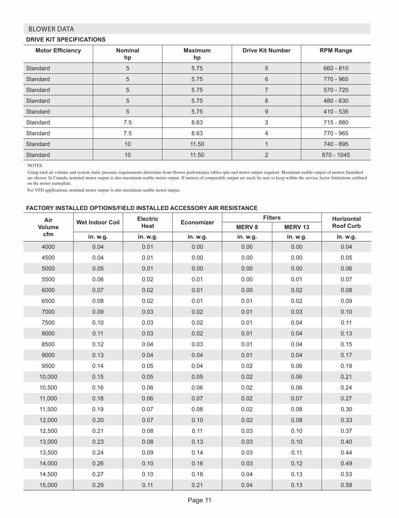
BLOWER DATADRIVE KIT SPECIFICATIONS
Motor Efficiency Nominal hp
Maximum hp
Drive Kit Number RPM Range
Standard 5 5.75 5 660 - 810
Standard 5 5.75 6 770 - 965
Standard 5 5.75 7 570 - 720
Standard 5 5.75 8 480 - 630
Standard 5 5.75 9 410 - 535
Standard 7.5 8.63 3 715 - 880
Standard 7.5 8.63 4 770 - 965
Standard 10 11.50 1 740 - 895
Standard 10 11.50 2 870 - 1045
NOTES
Using total air volume and system static pressure requirements determine from blower performance tables rpm and motor output required. Maximum usable output of motors furnished are shown. In Canada, nominal motor output is also maximum usable motor output. If motors of comparable output are used, be sure to keep within the service factor limitations outlined on the motor nameplate.
For VFD applications, nominal motor output is also maximum usable motor output.
FACTORY INSTALLED OPTIONS/FIELD INSTALLED ACCESSORY AIR RESISTANCE
Air Volume
cfm
Wet Indoor Coil Electric Heat Economizer
Filters Horizontal Roof CurbMERV 8 MERV 13
in. w.g. in. w.g. in. w.g. in. w.g. in. w.g. in. w.g.4000 0.04 0.01 0.00 0.00 0.00 0.04
4500 0.04 0.01 0.00 0.00 0.00 0.05
5000 0.05 0.01 0.00 0.00 0.00 0.06
5500 0.06 0.02 0.01 0.00 0.01 0.07
6000 0.07 0.02 0.01 0.00 0.02 0.08
6500 0.08 0.02 0.01 0.01 0.02 0.09
7000 0.09 0.03 0.02 0.01 0.03 0.10
7500 0.10 0.03 0.02 0.01 0.04 0.11
8000 0.11 0.03 0.02 0.01 0.04 0.13
8500 0.12 0.04 0.03 0.01 0.04 0.15
9000 0.13 0.04 0.04 0.01 0.04 0.17
9500 0.14 0.05 0.04 0.02 0.06 0.19
10,000 0.15 0.05 0.05 0.02 0.06 0.21
10,500 0.16 0.06 0.06 0.02 0.06 0.24
11,000 0.18 0.06 0.07 0.02 0.07 0.27
11,500 0.19 0.07 0.08 0.02 0.08 0.30
12,000 0.20 0.07 0.10 0.02 0.08 0.33
12,500 0.21 0.08 0.11 0.03 0.10 0.37
13,000 0.23 0.08 0.13 0.03 0.10 0.40
13,500 0.24 0.09 0.14 0.03 0.11 0.44
14,000 0.26 0.10 0.16 0.03 0.12 0.49
14,500 0.27 0.10 0.18 0.04 0.13 0.53
15,000 0.29 0.11 0.21 0.04 0.13 0.58
Page 12
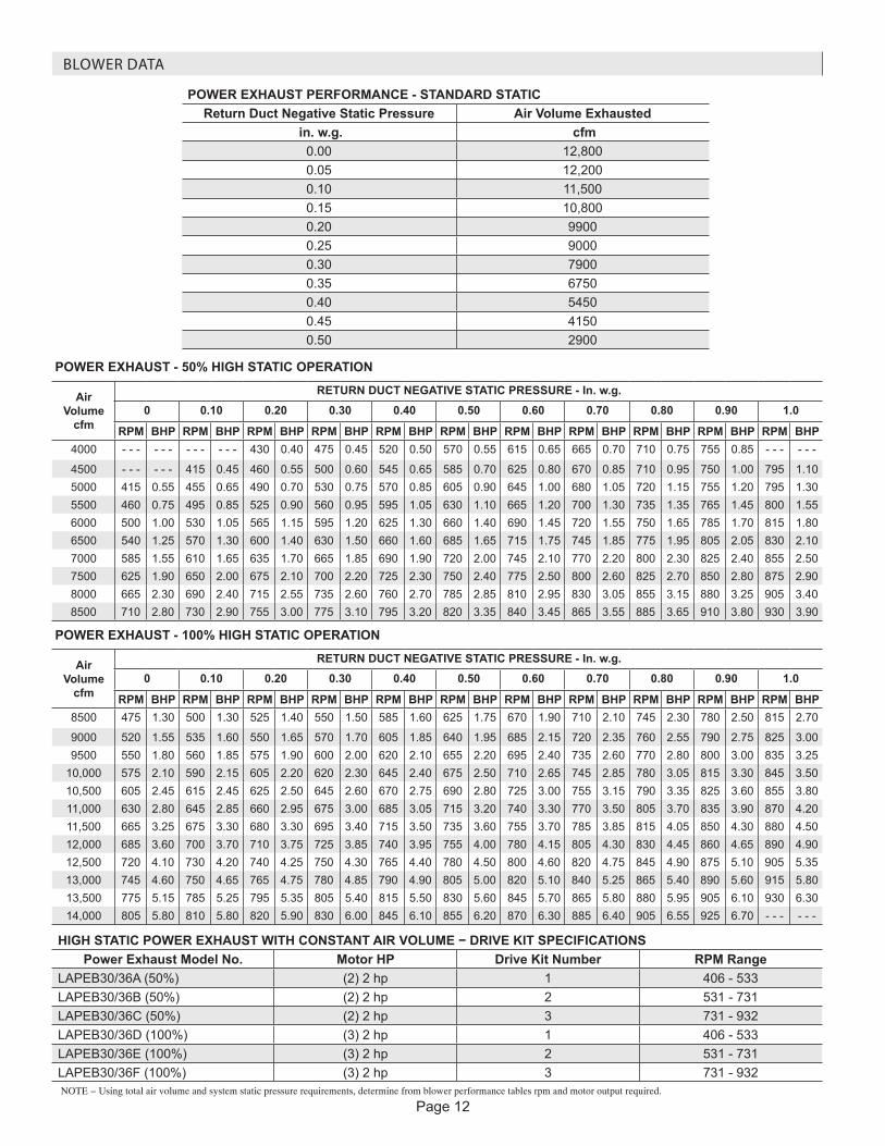
BLOWER DATA
POWER EXHAUST PERFORMANCE - STANDARD STATICReturn Duct Negative Static Pressure Air Volume Exhausted
in. w.g. cfm 0.00 12,8000.05 12,2000.10 11,5000.15 10,8000.20 99000.25 90000.30 79000.35 67500.40 54500.45 41500.50 2900
POWER EXHAUST - 50% HIGH STATIC OPERATION
Air Volume
cfm
RETURN DUCT NEGATIVE STATIC PRESSURE - In. w.g.0 0.10 0.20 0.30 0.40 0.50 0.60 0.70 0.80 0.90 1.0
RPM BHP RPM BHP RPM BHP RPM BHP RPM BHP RPM BHP RPM BHP RPM BHP RPM BHP RPM BHP RPM BHP4000 - - - - - - - - - - - - 430 0.40 475 0.45 520 0.50 570 0.55 615 0.65 665 0.70 710 0.75 755 0.85 - - - - - -
4500 - - - - - - 415 0.45 460 0.55 500 0.60 545 0.65 585 0.70 625 0.80 670 0.85 710 0.95 750 1.00 795 1.105000 415 0.55 455 0.65 490 0.70 530 0.75 570 0.85 605 0.90 645 1.00 680 1.05 720 1.15 755 1.20 795 1.305500 460 0.75 495 0.85 525 0.90 560 0.95 595 1.05 630 1.10 665 1.20 700 1.30 735 1.35 765 1.45 800 1.556000 500 1.00 530 1.05 565 1.15 595 1.20 625 1.30 660 1.40 690 1.45 720 1.55 750 1.65 785 1.70 815 1.806500 540 1.25 570 1.30 600 1.40 630 1.50 660 1.60 685 1.65 715 1.75 745 1.85 775 1.95 805 2.05 830 2.107000 585 1.55 610 1.65 635 1.70 665 1.85 690 1.90 720 2.00 745 2.10 770 2.20 800 2.30 825 2.40 855 2.507500 625 1.90 650 2.00 675 2.10 700 2.20 725 2.30 750 2.40 775 2.50 800 2.60 825 2.70 850 2.80 875 2.908000 665 2.30 690 2.40 715 2.55 735 2.60 760 2.70 785 2.85 810 2.95 830 3.05 855 3.15 880 3.25 905 3.408500 710 2.80 730 2.90 755 3.00 775 3.10 795 3.20 820 3.35 840 3.45 865 3.55 885 3.65 910 3.80 930 3.90
POWER EXHAUST - 100% HIGH STATIC OPERATION
Air Volume
cfm
RETURN DUCT NEGATIVE STATIC PRESSURE - In. w.g.0 0.10 0.20 0.30 0.40 0.50 0.60 0.70 0.80 0.90 1.0
RPM BHP RPM BHP RPM BHP RPM BHP RPM BHP RPM BHP RPM BHP RPM BHP RPM BHP RPM BHP RPM BHP8500 475 1.30 500 1.30 525 1.40 550 1.50 585 1.60 625 1.75 670 1.90 710 2.10 745 2.30 780 2.50 815 2.70
9000 520 1.55 535 1.60 550 1.65 570 1.70 605 1.85 640 1.95 685 2.15 720 2.35 760 2.55 790 2.75 825 3.009500 550 1.80 560 1.85 575 1.90 600 2.00 620 2.10 655 2.20 695 2.40 735 2.60 770 2.80 800 3.00 835 3.25
10,000 575 2.10 590 2.15 605 2.20 620 2.30 645 2.40 675 2.50 710 2.65 745 2.85 780 3.05 815 3.30 845 3.5010,500 605 2.45 615 2.45 625 2.50 645 2.60 670 2.75 690 2.80 725 3.00 755 3.15 790 3.35 825 3.60 855 3.8011,000 630 2.80 645 2.85 660 2.95 675 3.00 685 3.05 715 3.20 740 3.30 770 3.50 805 3.70 835 3.90 870 4.2011,500 665 3.25 675 3.30 680 3.30 695 3.40 715 3.50 735 3.60 755 3.70 785 3.85 815 4.05 850 4.30 880 4.5012,000 685 3.60 700 3.70 710 3.75 725 3.85 740 3.95 755 4.00 780 4.15 805 4.30 830 4.45 860 4.65 890 4.9012,500 720 4.10 730 4.20 740 4.25 750 4.30 765 4.40 780 4.50 800 4.60 820 4.75 845 4.90 875 5.10 905 5.3513,000 745 4.60 750 4.65 765 4.75 780 4.85 790 4.90 805 5.00 820 5.10 840 5.25 865 5.40 890 5.60 915 5.8013,500 775 5.15 785 5.25 795 5.35 805 5.40 815 5.50 830 5.60 845 5.70 865 5.80 880 5.95 905 6.10 930 6.3014,000 805 5.80 810 5.80 820 5.90 830 6.00 845 6.10 855 6.20 870 6.30 885 6.40 905 6.55 925 6.70 - - - - - -
HIGH STATIC POWER EXHAUST WITH CONSTANT AIR VOLUME − DRIVE KIT SPECIFICATIONSPower Exhaust Model No. Motor HP Drive Kit Number RPM Range
LAPEB30/36A (50%) (2) 2 hp 1 406 - 533 LAPEB30/36B (50%) (2) 2 hp 2 531 - 731 LAPEB30/36C (50%) (2) 2 hp 3 731 - 932 LAPEB30/36D (100%) (3) 2 hp 1 406 - 533 LAPEB30/36E (100%) (3) 2 hp 2 531 - 731 LAPEB30/36F (100%) (3) 2 hp 3 731 - 932 NOTE − Using total air volume and system static pressure requirements, determine from blower performance tables rpm and motor output required.

Page 13
BLOWER DATA
CEILING DIFFUSER AIR RESISTANCE - in. w.g.
Air Volume
cfm
Step-Down Diffuser Flush Diffuser
LARTD30/36SLAFD30/36S
2 Ends Open 1 Side/2 Ends Open All Ends & Sides Open
7500 0.37 0.31 0.25 0.29
8000 0.42 0.36 0.29 0.34
8500 0.48 0.41 0.34 0.39
9000 0.55 0.47 0.39 0.44
9500 0.62 0.53 0.45 0.51
10,000 0.70 0.60 0.51 0.57
10,500 0.78 0.68 0.58 0.65
11,000 0.87 0.76 0.65 0.72
11,500 0.97 0.85 0.73 0.81
12,000 1.08 0.94 0.82 0.9
12,500 1.19 1.04 0.91 0.99
13,000 1.30 1.15 1.00 1.10
13,500 1.43 1.26 1.10 1.20
14,000 1.56 1.38 1.20 1.31
14,500 1.69 1.50 1.31 1.43
15,000 1.84 1.63 1.43 1.56
CEILING DIFFUSER AIR THROW DATA - ft.
Air Volume cfm
1 Effective Throw Range - ft.
Step-Down Flush
9000 40 - 47 29 - 35
9500 43 - 50 33 - 41
10,000 46 - 54 37 - 46
10,500 50 - 58 42 - 51
11,000 53 - 61 46 - 56
11,500 55 - 64 50 - 61
12,000 58 - 67 54 - 66
12,500 61 - 71 58 - 71
13,000 64 - 74 62 - 75
13,500 67 - 77 66 - 79 1 Throw is the horizontal or vertical distance an airstream travels on leaving the outletor diffuser before the maximum velocity is reduced to 50 ft. per
minute. Four sides open.

Page 14
ELECTRICAL DATA 20 TON20 TON HIGH EFFICIENCY - VARIABLE AIR VOLUME (VAV) LCH242H4V1 Voltage - 60hz 208/230V - 3 Ph 460V - 3 Ph 575V - 3 PhCompressor 1 Rated Load Amps 13.5 8 5
Locked Rotor Amps 109 59 40Compressor 2 Rated Load Amps 13.5 8 5
Locked Rotor Amps 109 59 40Compressor 3 Rated Load Amps 13.5 8 5
Locked Rotor Amps 109 59 40Compressor 4 Rated Load Amps 13.5 8 5
Locked Rotor Amps 109 59 40Outdoor Fan Motors (6)
Full Load Amps(total)
2.4(14.4)
1.3(7.8)
1(6)
Standard Power Exhaust (3) 0.33 HP
Full Load Amps(total)
2.4(7.2)
1.3(3.9)
1(3)
50% High Static Power Exhaust (2) 2 HP
Full Load Amps(total)
7.5(15)
3.4(6.8)
2.7(5.4)
100% High Static Power Exhaust (3) 2 HP
Full Load Amps(total)
7.5(22.5)
3.4(10.2)
2.7(8.1)
Service Outlet 115V GFI (amps) 15 15 20Indoor Blower Motor
Horsepower 5 7.5 10 5 7.5 10 5 7.5 10Full Load Amps 16.7 24.2 30.8 7.6 11 14 6.1 9 11
2 Maximum Overcurrent Protection
Unit Only 100 110 125 50 60 70 35 45 50With (3) 0.33 HP
Standard Power Exhaust110 125 125 60 60 70 40 45 50
With 50% High Static Power Exhaust (2) 2 HP
110 125 150 60 70 70 45 50 50
With 100% High Static Power Exhaust (3) 2 HP
125 125 150 60 70 80 45 50 50
3 Minimum Circuit Ampacity
Unit Only 90 99 107 50 54 58 34 38 40With (3) 0.33 HP
Standard Power Exhaust97 106 115 54 58 62 37 41 43
With 50% High Static Power Exhaust (2) 2 HP
105 114 122 57 61 65 40 43 46
With 100% High Static Power Exhaust (3) 2 HP
112 122 130 60 64 68 42 46 48
NOTE - All units have a minimum Short Circuit Current Rating (SCCR) of 5000 amps.1 Extremes of operating range are plus and minus 10% of line voltage.2 HACR type breaker or fuse.3 Refer to National or Canadian Electrical Code manual to determine wire, fuse and disconnect size requirements.
Page 15
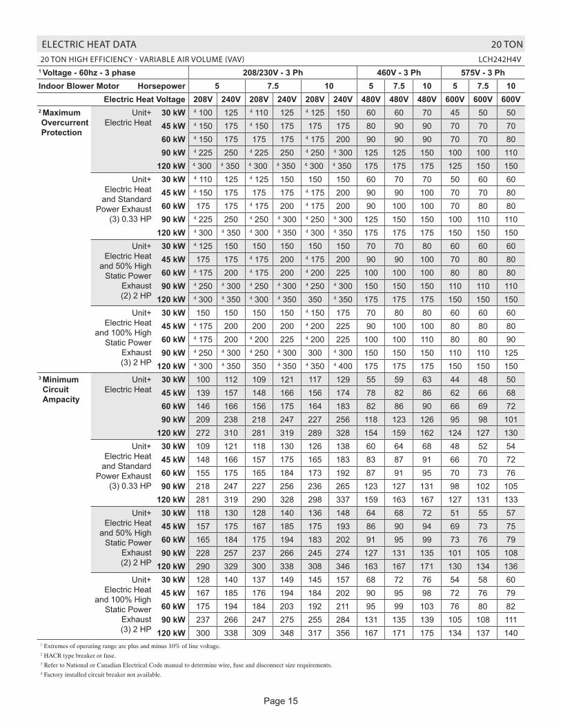
ELECTRIC HEAT DATA 20 TON20 TON HIGH EFFICIENCY - VARIABLE AIR VOLUME (VAV) LCH242H4V
1 Voltage - 60hz - 3 phase 208/230V - 3 Ph 460V - 3 Ph 575V - 3 PhIndoor Blower Motor Horsepower 5 7.5 10 5 7.5 10 5 7.5 10
Electric Heat Voltage 208V 240V 208V 240V 208V 240V 480V 480V 480V 600V 600V 600V2 Maximum Overcurrent Protection
Unit+ Electric Heat
30 kW 4 100 125 4 110 125 4 125 150 60 60 70 45 50 5045 kW 4 150 175 4 150 175 175 175 80 90 90 70 70 7060 kW 4 150 175 175 175 4 175 200 90 90 90 70 70 8090 kW 4 225 250 4 225 250 4 250 4 300 125 125 150 100 100 110
120 kW 4 300 4 350 4 300 4 350 4 300 4 350 175 175 175 125 150 150Unit+
Electric Heat and Standard
Power Exhaust (3) 0.33 HP
30 kW 4 110 125 4 125 150 150 150 60 70 70 50 60 6045 kW 4 150 175 175 175 4 175 200 90 90 100 70 70 8060 kW 175 175 4 175 200 4 175 200 90 100 100 70 80 8090 kW 4 225 250 4 250 4 300 4 250 4 300 125 150 150 100 110 110
120 kW 4 300 4 350 4 300 4 350 4 300 4 350 175 175 175 150 150 150Unit+
Electric Heat and 50% High
Static Power Exhaust (2) 2 HP
30 kW 4 125 150 150 150 150 150 70 70 80 60 60 6045 kW 175 175 4 175 200 4 175 200 90 90 100 70 80 8060 kW 4 175 200 4 175 200 4 200 225 100 100 100 80 80 8090 kW 4 250 4 300 4 250 4 300 4 250 4 300 150 150 150 110 110 110
120 kW 4 300 4 350 4 300 4 350 350 4 350 175 175 175 150 150 150Unit+
Electric Heat and 100% High
Static Power Exhaust
(3) 2 HP
30 kW 150 150 150 150 4 150 175 70 80 80 60 60 6045 kW 4 175 200 200 200 4 200 225 90 100 100 80 80 8060 kW 4 175 200 4 200 225 4 200 225 100 100 110 80 80 9090 kW 4 250 4 300 4 250 4 300 300 4 300 150 150 150 110 110 125
120 kW 4 300 4 350 350 4 350 4 350 4 400 175 175 175 150 150 1503 Minimum Circuit Ampacity
Unit+ Electric Heat
30 kW 100 112 109 121 117 129 55 59 63 44 48 5045 kW 139 157 148 166 156 174 78 82 86 62 66 6860 kW 146 166 156 175 164 183 82 86 90 66 69 7290 kW 209 238 218 247 227 256 118 123 126 95 98 101
120 kW 272 310 281 319 289 328 154 159 162 124 127 130Unit+
Electric Heat and Standard
Power Exhaust (3) 0.33 HP
30 kW 109 121 118 130 126 138 60 64 68 48 52 5445 kW 148 166 157 175 165 183 83 87 91 66 70 7260 kW 155 175 165 184 173 192 87 91 95 70 73 7690 kW 218 247 227 256 236 265 123 127 131 98 102 105
120 kW 281 319 290 328 298 337 159 163 167 127 131 133Unit+
Electric Heat and 50% High
Static Power Exhaust (2) 2 HP
30 kW 118 130 128 140 136 148 64 68 72 51 55 5745 kW 157 175 167 185 175 193 86 90 94 69 73 7560 kW 165 184 175 194 183 202 91 95 99 73 76 7990 kW 228 257 237 266 245 274 127 131 135 101 105 108
120 kW 290 329 300 338 308 346 163 167 171 130 134 136Unit+
Electric Heat and 100% High
Static Power Exhaust
(3) 2 HP
30 kW 128 140 137 149 145 157 68 72 76 54 58 6045 kW 167 185 176 194 184 202 90 95 98 72 76 7960 kW 175 194 184 203 192 211 95 99 103 76 80 8290 kW 237 266 247 275 255 284 131 135 139 105 108 111
120 kW 300 338 309 348 317 356 167 171 175 134 137 1401 Extremes of operating range are plus and minus 10% of line voltage. 2 HACR type breaker or fuse.3 Refer to National or Canadian Electrical Code manual to determine wire, fuse and disconnect size requirements.4 Factory installed circuit breaker not available.
Page 16
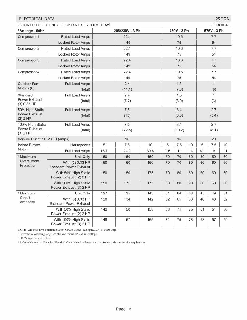
ELECTRICAL DATA 25 TON25 TON HIGH EFFICIENCY - CONSTANT AIR VOLUME (CAV) LCH300H4B1 Voltage - 60hz 208/230V - 3 Ph 460V - 3 Ph 575V - 3 PhCompressor 1 Rated Load Amps 22.4 10.6 7.7
Locked Rotor Amps 149 75 54Compressor 2 Rated Load Amps 22.4 10.6 7.7
Locked Rotor Amps 149 75 54Compressor 3 Rated Load Amps 22.4 10.6 7.7
Locked Rotor Amps 149 75 54Compressor 4 Rated Load Amps 22.4 10.6 7.7
Locked Rotor Amps 149 75 54Outdoor Fan Motors (6)
Full Load Amps(total)
2.4(14.4)
1.3(7.8)
1(6)
Standard Power Exhaust (3) 0.33 HP
Full Load Amps(total)
2.4(7.2)
1.3(3.9)
1(3)
50% High Static Power Exhaust (2) 2 HP
Full Load Amps(total)
7.5(15)
3.4(6.8)
2.7(5.4)
100% High Static Power Exhaust (3) 2 HP
Full Load Amps(total)
7.5(22.5)
3.4(10.2)
2.7(8.1)
Service Outlet 115V GFI (amps) 15 15 20Indoor Blower Motor
Horsepower 5 7.5 10 5 7.5 10 5 7.5 10Full Load Amps 16.7 24.2 30.8 7.6 11 14 6.1 9 11
2 Maximum Overcurrent Protection
Unit Only 150 150 150 70 70 80 50 50 60With (3) 0.33 HP
Standard Power Exhaust150 150 150 70 70 80 60 60 60
With 50% High Static Power Exhaust (2) 2 HP
150 150 175 70 80 80 60 60 60
With 100% High Static Power Exhaust (3) 2 HP
150 175 175 80 80 90 60 60 60
3 Minimum Circuit Ampacity
Unit Only 127 135 143 61 64 68 45 49 51With (3) 0.33 HP
Standard Power Exhaust128 134 142 62 65 68 46 48 52
With 50% High Static Power Exhaust (2) 2 HP
142 150 158 68 71 75 51 54 56
With 100% High Static Power Exhaust (3) 2 HP
149 157 165 71 75 78 53 57 59
NOTE - All units have a minimum Short Circuit Current Rating (SCCR) of 5000 amps.1 Extremes of operating range are plus and minus 10% of line voltage.2 HACR type breaker or fuse.3 Refer to National or Canadian Electrical Code manual to determine wire, fuse and disconnect size requirements.

Page 17
ELECTRIC HEAT DATA 25 TON25 TON HIGH EFFICIENCY - CONSTANT AIR VOLUME (CAV) LCH300H4B
1 Voltage - 60hz - 3 phase 208/230V - 3 Ph 460V - 3 Ph 575V - 3 PhIndoor Blower Motor Horsepower 5 7.5 10 5 7.5 10 5 7.5 10
Electric Heat Voltage 208V 240V 208V 240V 208V 240V 480V 480V 480V 600V 600V 600V2 Maximum Overcurrent Protection
Unit+ Electric Heat
30 kW 150 150 150 150 150 150 70 70 80 50 50 6045 kW 4 150 175 4 150 175 175 175 80 90 90 70 70 7060 kW 4 150 175 175 175 4 175 200 90 90 90 70 70 8090 kW 4 225 250 4 225 250 4 250 4 300 125 125 150 100 100 110
120 kW 4 300 4 350 4 300 4 350 4 300 4 350 175 175 175 125 150 150Unit+
Electric Heat and Standard
Power Exhaust (3) 0.33 HP
30 kW 150 150 150 150 150 150 70 70 70 50 50 6045 kW 4 150 175 4 150 175 175 175 80 90 90 70 70 7060 kW 4 150 175 175 175 4 175 200 90 90 100 70 70 8090 kW 4 225 250 4 225 250 4 250 4 300 125 125 150 100 100 110
120 kW 4 300 4 350 4 300 4 350 4 300 4 350 175 175 175 125 150 150Unit+
Electric Heat and 50% High
Static Power Exhaust (2) 2 HP
30 kW 150 150 150 150 175 175 70 80 80 60 60 6045 kW 175 175 4 175 200 4 175 200 90 90 100 70 80 8060 kW 4 175 200 4 175 200 4 200 225 100 100 100 80 80 8090 kW 4 250 4 300 4 250 4 300 4 250 4 300 150 150 150 110 110 110
120 kW 4 300 4 350 4 300 4 350 350 4 350 175 175 175 150 150 150Unit+
Electric Heat and 100% High
Static Power Exhaust
(3) 2 HP
30 kW 150 150 175 175 175 175 80 80 90 60 60 6045 kW 4 175 200 200 200 4 200 225 90 100 100 80 80 8060 kW 4 175 200 4 200 225 4 200 225 100 100 110 80 80 9090 kW 4 250 4 300 4 250 4 300 300 4 300 150 150 150 110 110 125
120 kW 4 300 4 350 350 4 350 4 350 4 400 175 175 175 150 150 1503 Minimum Circuit Ampacity
Unit+ Electric Heat
30 kW 127 127 135 135 143 143 61 64 68 45 49 5145 kW 139 157 148 166 156 174 78 82 86 62 66 6860 kW 146 166 156 175 164 183 82 86 90 66 69 7290 kW 209 238 218 247 227 256 118 123 126 95 98 101
120 kW 272 310 281 319 289 328 154 159 162 124 127 130Unit+
Electric Heat and Standard
Power Exhaust (3) 0.33 HP
30 kW 128 128 134 134 142 142 62 65 68 46 48 5245 kW 140 158 148 166 157 175 79 83 87 63 66 7060 kW 148 167 155 175 165 184 84 87 91 67 70 7390 kW 210 239 218 247 227 256 120 123 127 96 98 102
120 kW 273 311 281 319 290 328 156 159 163 125 127 131Unit+
Electric Heat and 50% High
Static Power Exhaust (2) 2 HP
30 kW 142 142 150 150 158 158 68 71 75 51 55 5745 kW 157 175 167 185 175 193 86 90 94 69 73 7560 kW 165 184 175 194 183 202 91 95 99 73 76 7990 kW 228 257 237 266 245 274 127 131 135 101 105 108
120 kW 290 329 300 338 308 346 163 167 171 130 134 136Unit+
Electric Heat and 100% High
Static Power Exhaust
(3) 2 HP
30 kW 149 149 157 157 165 165 71 75 78 54 58 6045 kW 167 185 176 194 184 202 90 95 98 72 76 7960 kW 175 194 184 203 192 211 95 99 103 76 80 8290 kW 237 266 247 275 255 284 131 135 139 105 108 111
120 kW 300 338 309 348 317 356 167 171 175 134 137 1401 Extremes of operating range are plus and minus 10% of line voltage. 2 HACR type breaker or fuse.3 Refer to National or Canadian Electrical Code manual to determine wire, fuse and disconnect size requirements.4 Factory installed circuit breaker not available.

Page 18
ELECTRICAL DATA 25 TON25 TON HIGH EFFICIENCY - VARIABLE AND MULTI-STAGE AIR VOLUME LCH300H4V,M1 Voltage - 60hz 208/230V - 3 Ph 460V - 3 Ph 575V - 3 PhCompressor 1 Rated Load Amps 22.4 10.6 7.7
Locked Rotor Amps 149 75 54Compressor 2 Rated Load Amps 22.4 10.6 7.7
Locked Rotor Amps 149 75 54Compressor 3 Rated Load Amps 22.4 10.6 7.7
Locked Rotor Amps 149 75 54Compressor 4 Rated Load Amps 22.4 10.6 7.7
Locked Rotor Amps 149 75 54Outdoor Fan Motors (6)
Full Load Amps(total)
2.4(14.4)
1.3(7.8)
1(6)
Standard Power Exhaust (3) 0.33 HP
Full Load Amps(total)
2.4(7.2)
1.3(3.9)
1(3)
50% High Static Power Exhaust (2) 2 HP
Full Load Amps(total)
7.5(15)
3.4(6.8)
2.7(5.4)
100% High Static Power Exhaust (3) 2 HP
Full Load Amps(total)
7.5(22.5)
3.4(10.2)
2.7(8.1)
Service Outlet 115V GFI (amps) 15 15 20Indoor Blower Motor
Horsepower 5 7.5 10 5 7.5 10 5 7.5 10Full Load Amps 16.7 24.2 30.8 7.6 11 14 6.1 9 11
2 Maximum Overcurrent Protection
Unit Only 150 150 150 70 70 80 50 50 60With (3) 0.33 HP
Standard Power Exhaust150 150 175 70 70 80 50 60 60
With 50% High Static Power Exhaust (2) 2 HP
150 150 175 70 80 80 60 60 60
With 100% High Static Power Exhaust (3) 2 HP
150 175 175 80 80 90 60 60 60
3 Minimum Circuit Ampacity
Unit Only 127 135 143 61 64 68 45 49 51With (3) 0.33 HP
Standard Power Exhaust134 142 150 65 68 72 48 52 54
With 50% High Static Power Exhaust (2) 2 HP
142 150 158 68 71 75 51 54 56
With 100% High Static Power Exhaust (3) 2 HP
149 157 165 71 75 78 53 57 59
NOTE - All units have a minimum Short Circuit Current Rating (SCCR) of 5000 amps.1 Extremes of operating range are plus and minus 10% of line voltage.2 HACR type breaker or fuse.3 Refer to National or Canadian Electrical Code manual to determine wire, fuse and disconnect size requirements.
Page 19
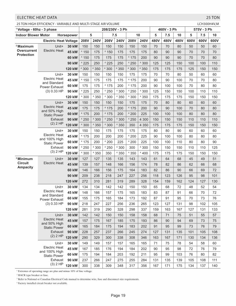
ELECTRIC HEAT DATA 25 TON25 TON HIGH EFFICIENCY - VARIABLE AND MULTI-STAGE AIR VOLUME LCH300H4V,M
1 Voltage - 60hz - 3 phase 208/230V - 3 Ph 460V - 3 Ph 575V - 3 PhIndoor Blower Motor Horsepower 5 7.5 10 5 7.5 10 5 7.5 10
Electric Heat Voltage 208V 240V 208V 240V 208V 240V 480V 480V 480V 600V 600V 600V2 Maximum Overcurrent Protection
Unit+ Electric Heat
30 kW 150 150 150 150 150 150 70 70 80 50 50 6045 kW 4 150 175 4 150 175 175 175 80 90 90 70 70 7060 kW 4 150 175 175 175 4 175 200 90 90 90 70 70 8090 kW 4 225 250 4 225 250 4 250 4 300 125 125 150 100 100 110
120 kW 4 300 4 350 4 300 4 350 4 300 4 350 175 175 175 125 150 150Unit+
Electric Heat and Standard
Power Exhaust (3) 0.33 HP
30 kW 150 150 150 150 175 175 70 70 80 50 60 6045 kW 4 150 175 175 175 4 175 200 90 90 100 70 70 8060 kW 175 175 4 175 200 4 175 200 90 100 100 70 80 8090 kW 4 225 250 4 250 4 300 4 250 4 300 125 150 150 100 110 110
120 kW 4 300 4 350 4 300 4 350 4 300 4 350 175 175 175 150 150 150Unit+
Electric Heat and 50% High
Static Power Exhaust (2) 2 HP
30 kW 150 150 150 150 175 175 70 80 80 60 60 6045 kW 175 175 4 175 200 4 175 200 90 90 100 70 80 8060 kW 4 175 200 4 175 200 4 200 225 100 100 100 80 80 8090 kW 4 250 4 300 4 250 4 300 4 250 4 300 150 150 150 110 110 110
120 kW 4 300 4 350 4 300 4 350 350 4 350 175 175 175 150 150 150Unit+
Electric Heat and 100% High
Static Power Exhaust
(3) 2 HP
30 kW 150 150 175 175 175 175 80 80 90 60 60 6045 kW 4 175 200 200 200 4 200 225 90 100 100 80 80 8060 kW 4 175 200 4 200 225 4 200 225 100 100 110 80 80 9090 kW 4 250 4 300 4 250 4 300 300 4 300 150 150 150 110 110 125
120 kW 4 300 4 350 350 4 350 4 350 4 400 175 175 175 150 150 1503 Minimum Circuit Ampacity
Unit+ Electric Heat
30 kW 127 127 135 135 143 143 61 64 68 45 49 5145 kW 139 157 148 166 156 174 78 82 86 62 66 6860 kW 146 166 156 175 164 183 82 86 90 66 69 7290 kW 209 238 218 247 227 256 118 123 126 95 98 101
120 kW 272 310 281 319 289 328 154 159 162 124 127 130Unit+
Electric Heat and Standard
Power Exhaust (3) 0.33 HP
30 kW 134 134 142 142 150 150 65 68 72 48 52 5445 kW 148 166 157 175 165 183 83 87 91 66 70 7260 kW 155 175 165 184 173 192 87 91 95 70 73 7690 kW 218 247 227 256 236 265 123 127 131 98 102 105
120 kW 281 319 290 328 298 337 159 163 167 127 131 133Unit+
Electric Heat and 50% High
Static Power Exhaust (2) 2 HP
30 kW 142 142 150 150 158 158 68 71 75 51 55 5745 kW 157 175 167 185 175 193 86 90 94 69 73 7560 kW 165 184 175 194 183 202 91 95 99 73 76 7990 kW 228 257 237 266 245 274 127 131 135 101 105 108
120 kW 290 329 300 338 308 346 163 167 171 130 134 136Unit+
Electric Heat and 100% High
Static Power Exhaust
(3) 2 HP
30 kW 149 149 157 157 165 165 71 75 78 54 58 6045 kW 167 185 176 194 184 202 90 95 98 72 76 7960 kW 175 194 184 203 192 211 95 99 103 76 80 8290 kW 237 266 247 275 255 284 131 135 139 105 108 111
120 kW 300 338 309 348 317 356 167 171 175 134 137 1401 Extremes of operating range are plus and minus 10% of line voltage. 2 HACR type breaker or fuse.3 Refer to National or Canadian Electrical Code manual to determine wire, fuse and disconnect size requirements.4 Factory installed circuit breaker not available.
Page 20
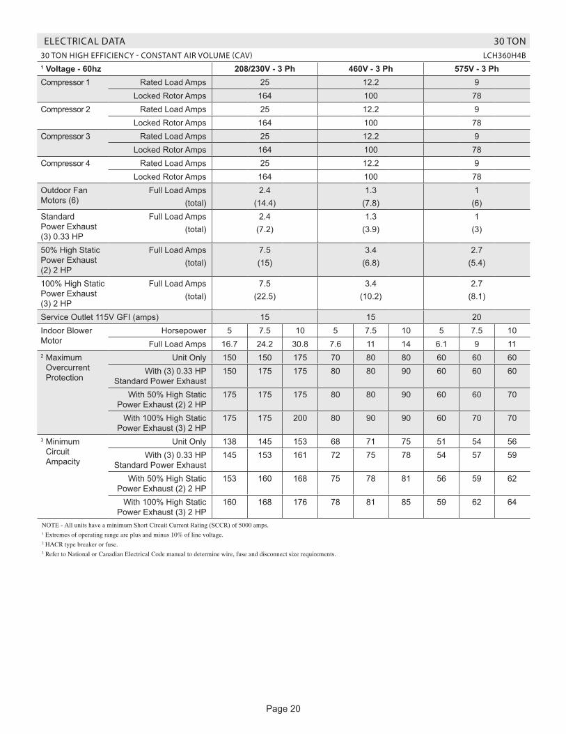
ELECTRICAL DATA 30 TON30 TON HIGH EFFICIENCY - CONSTANT AIR VOLUME (CAV) LCH360H4B1 Voltage - 60hz 208/230V - 3 Ph 460V - 3 Ph 575V - 3 PhCompressor 1 Rated Load Amps 25 12.2 9
Locked Rotor Amps 164 100 78Compressor 2 Rated Load Amps 25 12.2 9
Locked Rotor Amps 164 100 78Compressor 3 Rated Load Amps 25 12.2 9
Locked Rotor Amps 164 100 78Compressor 4 Rated Load Amps 25 12.2 9
Locked Rotor Amps 164 100 78Outdoor Fan Motors (6)
Full Load Amps(total)
2.4(14.4)
1.3(7.8)
1(6)
Standard Power Exhaust (3) 0.33 HP
Full Load Amps(total)
2.4(7.2)
1.3(3.9)
1(3)
50% High Static Power Exhaust (2) 2 HP
Full Load Amps(total)
7.5(15)
3.4(6.8)
2.7(5.4)
100% High Static Power Exhaust (3) 2 HP
Full Load Amps(total)
7.5(22.5)
3.4(10.2)
2.7(8.1)
Service Outlet 115V GFI (amps) 15 15 20Indoor Blower Motor
Horsepower 5 7.5 10 5 7.5 10 5 7.5 10Full Load Amps 16.7 24.2 30.8 7.6 11 14 6.1 9 11
2 Maximum Overcurrent Protection
Unit Only 150 150 175 70 80 80 60 60 60With (3) 0.33 HP
Standard Power Exhaust150 175 175 80 80 90 60 60 60
With 50% High Static Power Exhaust (2) 2 HP
175 175 175 80 80 90 60 60 70
With 100% High Static Power Exhaust (3) 2 HP
175 175 200 80 90 90 60 70 70
3 Minimum Circuit Ampacity
Unit Only 138 145 153 68 71 75 51 54 56With (3) 0.33 HP
Standard Power Exhaust145 153 161 72 75 78 54 57 59
With 50% High Static Power Exhaust (2) 2 HP
153 160 168 75 78 81 56 59 62
With 100% High Static Power Exhaust (3) 2 HP
160 168 176 78 81 85 59 62 64
NOTE - All units have a minimum Short Circuit Current Rating (SCCR) of 5000 amps.1 Extremes of operating range are plus and minus 10% of line voltage.2 HACR type breaker or fuse.3 Refer to National or Canadian Electrical Code manual to determine wire, fuse and disconnect size requirements.

Page 21
ELECTRIC HEAT DATA 30 TON30 TON HIGH EFFICIENCY - CONSTANT AIR VOLUME (CAV) LCH360H4B
1 Voltage - 60hz - 3 phase 208/230V - 3 Ph 460V - 3 Ph 575V - 3 PhIndoor Blower Motor Horsepower 5 7.5 10 5 7.5 10 5 7.5 10
Electric Heat Voltage 208V 240V 208V 240V 208V 240V 480V 480V 480V 600V 600V 600V2 Maximum Overcurrent Protection
Unit+ Electric Heat
30 kW 150 150 150 150 175 175 70 80 80 60 60 6045 kW 4 150 175 4 150 175 175 175 80 90 90 70 70 7060 kW 4 150 175 175 175 4 175 200 90 90 90 70 70 8090 kW 4 225 250 4 225 250 4 250 4 300 125 125 150 100 100 110
120 kW 4 300 4 350 4 300 4 350 4 300 4 350 175 175 175 125 150 150Unit+
Electric Heat and Standard
Power Exhaust (3) 0.33 HP
30 kW 150 150 175 175 175 175 80 80 90 60 60 6045 kW 4 150 175 175 175 4 175 200 90 90 100 70 70 8060 kW 175 175 4 175 200 4 175 200 90 100 100 70 80 8090 kW 4 225 250 4 250 4 300 4 250 4 300 125 150 150 100 110 110
120 kW 4 300 4 350 4 300 4 350 4 300 4 350 175 175 175 150 150 150Unit+
Electric Heat and 50% High
Static Power Exhaust (2) 2 HP
30 kW 175 175 175 175 175 175 80 80 90 60 60 7045 kW 175 175 4 175 200 4 175 200 90 90 100 70 80 8060 kW 4 175 200 4 175 200 4 200 225 100 100 100 80 80 8090 kW 4 250 4 300 4 250 4 300 4 250 4 300 150 150 150 110 110 110
120 kW 4 300 4 350 4 300 4 350 350 4 350 175 175 175 150 150 150Unit+
Electric Heat and 100% High
Static Power Exhaust
(3) 2 HP
30 kW 175 175 175 175 200 200 80 90 90 60 70 7045 kW 4 175 200 200 200 4 200 225 90 100 100 80 80 8060 kW 4 175 200 4 200 225 4 200 225 100 100 110 80 80 9090 kW 4 250 4 300 4 250 4 300 300 4 300 150 150 150 110 110 125
120 kW 4 300 4 350 350 4 350 4 350 4 400 175 175 175 150 150 1503 Minimum Circuit Ampacity
Unit+ Electric Heat
30 kW 138 138 145 145 153 153 68 71 75 51 54 5645 kW 139 157 148 166 156 174 78 82 86 62 66 6860 kW 146 166 156 175 164 183 82 86 90 66 69 7290 kW 209 238 218 247 227 256 118 123 126 95 98 101
120 kW 272 310 281 319 289 328 154 159 162 124 127 130Unit+
Electric Heat and Standard
Power Exhaust (3) 0.33 HP
30 kW 145 145 153 153 161 161 72 75 78 54 57 5945 kW 148 166 157 175 165 183 83 87 91 66 70 7260 kW 155 175 165 184 173 192 87 91 95 70 73 7690 kW 218 247 227 256 236 265 123 127 131 98 102 105
120 kW 281 319 290 328 298 337 159 163 167 127 131 133Unit+
Electric Heat and 50% High
Static Power Exhaust (2) 2 HP
30 kW 153 153 160 160 168 168 75 78 81 56 59 6245 kW 157 175 167 185 175 193 86 90 94 69 73 7560 kW 165 184 175 194 183 202 91 95 99 73 76 7990 kW 228 257 237 266 245 274 127 131 135 101 105 108
120 kW 290 329 300 338 308 346 163 167 171 130 134 136Unit+
Electric Heat and 100% High
Static Power Exhaust
(3) 2 HP
30 kW 160 160 168 168 176 176 78 81 85 59 62 6445 kW 167 185 176 194 184 202 90 95 98 72 76 7960 kW 175 194 184 203 192 211 95 99 103 76 80 8290 kW 237 266 247 275 255 284 131 135 139 105 108 111
120 kW 300 338 309 348 317 356 167 171 175 134 137 1401 Extremes of operating range are plus and minus 10% of line voltage. 2 HACR type breaker or fuse.3 Refer to National or Canadian Electrical Code manual to determine wire, fuse and disconnect size requirements.4 Factory installed circuit breaker not available.
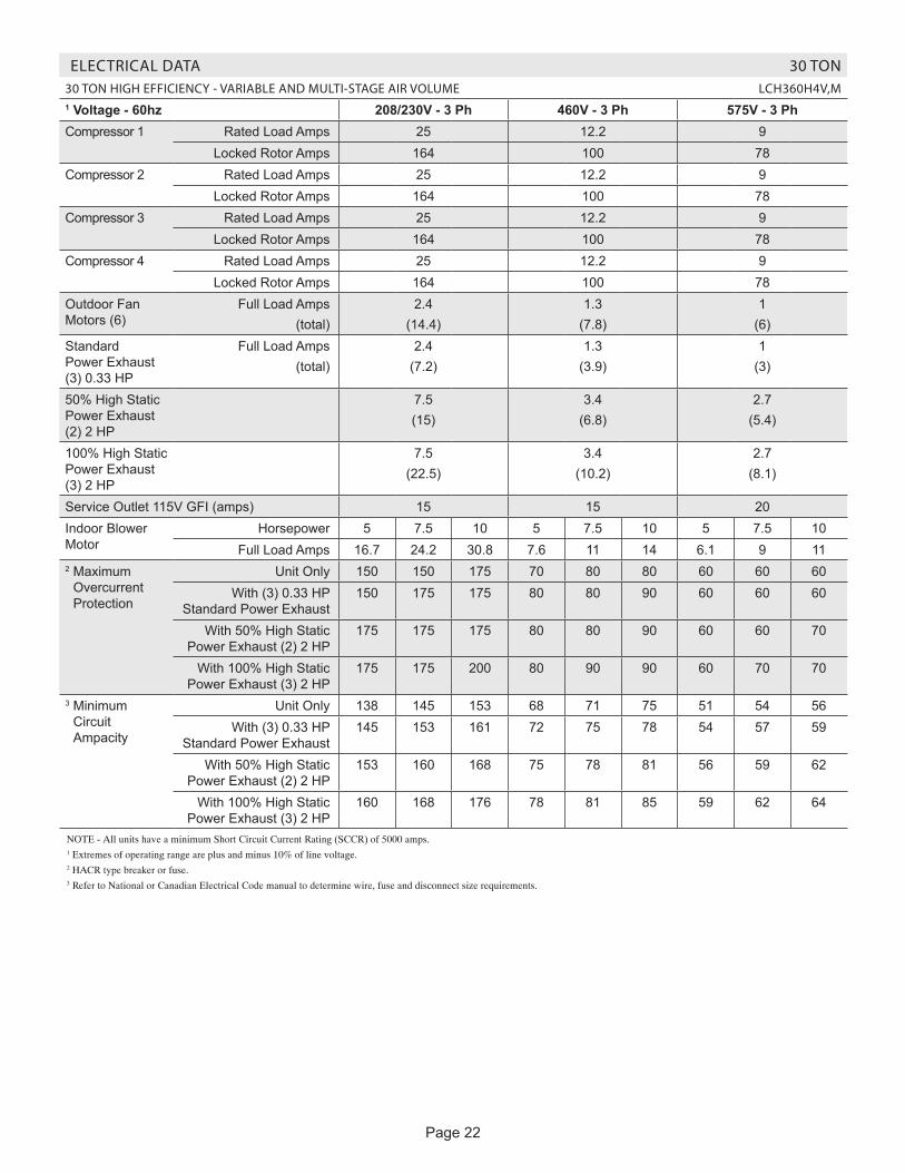
Page 22
ELECTRICAL DATA 30 TON30 TON HIGH EFFICIENCY - VARIABLE AND MULTI-STAGE AIR VOLUME LCH360H4V,M1 Voltage - 60hz 208/230V - 3 Ph 460V - 3 Ph 575V - 3 PhCompressor 1 Rated Load Amps 25 12.2 9
Locked Rotor Amps 164 100 78Compressor 2 Rated Load Amps 25 12.2 9
Locked Rotor Amps 164 100 78Compressor 3 Rated Load Amps 25 12.2 9
Locked Rotor Amps 164 100 78Compressor 4 Rated Load Amps 25 12.2 9
Locked Rotor Amps 164 100 78Outdoor Fan Motors (6)
Full Load Amps(total)
2.4(14.4)
1.3(7.8)
1(6)
Standard Power Exhaust (3) 0.33 HP
Full Load Amps(total)
2.4(7.2)
1.3(3.9)
1(3)
50% High Static Power Exhaust (2) 2 HP
7.5(15)
3.4(6.8)
2.7(5.4)
100% High Static Power Exhaust (3) 2 HP
7.5(22.5)
3.4(10.2)
2.7(8.1)
Service Outlet 115V GFI (amps) 15 15 20Indoor Blower Motor
Horsepower 5 7.5 10 5 7.5 10 5 7.5 10Full Load Amps 16.7 24.2 30.8 7.6 11 14 6.1 9 11
2 Maximum Overcurrent Protection
Unit Only 150 150 175 70 80 80 60 60 60With (3) 0.33 HP
Standard Power Exhaust150 175 175 80 80 90 60 60 60
With 50% High Static Power Exhaust (2) 2 HP
175 175 175 80 80 90 60 60 70
With 100% High Static Power Exhaust (3) 2 HP
175 175 200 80 90 90 60 70 70
3 Minimum Circuit Ampacity
Unit Only 138 145 153 68 71 75 51 54 56With (3) 0.33 HP
Standard Power Exhaust145 153 161 72 75 78 54 57 59
With 50% High Static Power Exhaust (2) 2 HP
153 160 168 75 78 81 56 59 62
With 100% High Static Power Exhaust (3) 2 HP
160 168 176 78 81 85 59 62 64
NOTE - All units have a minimum Short Circuit Current Rating (SCCR) of 5000 amps.1 Extremes of operating range are plus and minus 10% of line voltage.2 HACR type breaker or fuse.3 Refer to National or Canadian Electrical Code manual to determine wire, fuse and disconnect size requirements.

Page 23
ELECTRIC HEAT DATA 30 TON30 TON HIGH EFFICIENCY - VARIABLE AND MULTI-STAGE AIR VOLUME LCH360H4V,M
1 Voltage - 60hz - 3 phase 208/230V - 3 Ph 460V - 3 Ph 575V - 3 PhIndoor Blower Motor Horsepower 5 7.5 10 5 7.5 10 5 7.5 10
Electric Heat Voltage 208V 240V 208V 240V 208V 240V 480V 480V 480V 600V 600V 600V2 Maximum Overcurrent Protection
Unit+ Electric Heat
30 kW 150 150 150 150 175 175 70 80 80 60 60 6045 kW 4 150 175 4 150 175 175 175 80 90 90 70 70 7060 kW 4 150 175 175 175 4 175 200 90 90 90 70 70 8090 kW 4 225 250 4 225 250 4 250 4 300 125 125 150 100 100 110
120 kW 4 300 4 350 4 300 4 350 4 300 4 350 175 175 175 125 150 150Unit+
Electric Heat and Standard
Power Exhaust (3) 0.33 HP
30 kW 150 150 175 175 175 175 80 80 90 60 60 6045 kW 4 150 175 175 175 4 175 200 90 90 100 70 70 8060 kW 175 175 4 175 200 4 175 200 90 100 100 70 80 8090 kW 4 225 250 4 250 4 300 4 250 4 300 125 150 150 100 110 110
120 kW 4 300 4 350 4 300 4 350 4 300 4 350 175 175 175 150 150 150Unit+
Electric Heat and 50% High
Static Power Exhaust (2) 2 HP
30 kW 175 175 175 175 175 175 80 80 90 60 60 7045 kW 175 175 4 175 200 4 175 200 90 90 100 70 80 8060 kW 4 175 200 4 175 200 4 200 225 100 100 100 80 80 8090 kW 4 250 4 300 4 250 4 300 4 250 4 300 150 150 150 110 110 110
120 kW 4 300 4 350 4 300 4 350 350 4 350 175 175 175 150 150 150Unit+
Electric Heat and 100% High
Static Power Exhaust
(3) 2 HP
30 kW 175 175 175 175 200 200 80 90 90 60 70 7045 kW 4 175 200 200 200 4 200 225 90 100 100 80 80 8060 kW 4 175 200 4 200 225 4 200 225 100 100 110 80 80 9090 kW 4 250 4 300 4 250 4 300 300 4 300 150 150 150 110 110 125
120 kW 4 300 4 350 350 4 350 4 350 4 400 175 175 175 150 150 1503 Minimum Circuit Ampacity
Unit+ Electric Heat
30 kW 138 138 145 145 153 153 68 71 75 51 54 5645 kW 139 157 148 166 156 174 78 82 86 62 66 6860 kW 146 166 156 175 164 183 82 86 90 66 69 7290 kW 209 238 218 247 227 256 118 123 126 95 98 101
120 kW 272 310 281 319 289 328 154 159 162 124 127 130Unit+
Electric Heat and Standard
Power Exhaust (3) 0.33 HP
30 kW 145 145 153 153 161 161 72 75 78 54 57 5945 kW 148 166 157 175 165 183 83 87 91 66 70 7260 kW 155 175 165 184 173 192 87 91 95 70 73 7690 kW 218 247 227 256 236 265 123 127 131 98 102 105
120 kW 281 319 290 328 298 337 159 163 167 127 131 133Unit+
Electric Heat and 50% High
Static Power Exhaust (2) 2 HP
30 kW 153 153 160 160 168 168 75 78 81 56 59 6245 kW 157 175 167 185 175 193 86 90 94 69 73 7560 kW 165 184 175 194 183 202 91 95 99 73 76 7990 kW 228 257 237 266 245 274 127 131 135 101 105 108
120 kW 290 329 300 338 308 346 163 167 171 130 134 136Unit+
Electric Heat and 100% High
Static Power Exhaust
(3) 2 HP
30 kW 160 160 168 168 176 176 78 81 85 59 62 6445 kW 167 185 176 194 184 202 90 95 98 72 76 7960 kW 175 194 184 203 192 211 95 99 103 76 80 8290 kW 237 266 247 275 255 284 131 135 139 105 108 111
120 kW 300 338 309 348 317 356 167 171 175 134 137 1401 Extremes of operating range are plus and minus 10% of line voltage. 2 HACR type breaker or fuse.3 Refer to National or Canadian Electrical Code manual to determine wire, fuse and disconnect size requirements.4 Factory installed circuit breaker not available.
Page 24
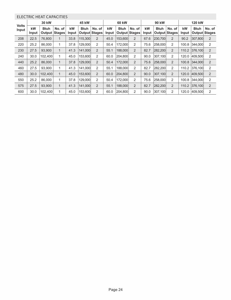
ELECTRIC HEAT CAPACITIES
Volts Input
30 kW 45 kW 60 kW 90 kW 120 kWkW
Input Btuh
Output No. of Stages
kW Input
Btuh Output
No. of Stages
kW Input
Btuh Output
No. of Stages
kW Input
Btuh Output
No. of Stages
kW Input
Btuh Output
No. of Stages
208 22.5 76,800 1 33.8 115,300 2 45.0 153,600 2 67.6 230,700 2 90.2 307,800 2
220 25.2 86,000 1 37.8 129,000 2 50.4 172,000 2 75.6 258,000 2 100.8 344,000 2
230 27.5 93,900 1 41.3 141,000 2 55.1 188,000 2 82.7 282,200 2 110.2 376,100 2
240 30.0 102,400 1 45.0 153,600 2 60.0 204,800 2 90.0 307,100 2 120.0 409,500 2
440 25.2 86,000 1 37.8 129,000 2 50.4 172,000 2 75.6 258,000 2 100.8 344,000 2
460 27.5 93,900 1 41.3 141,000 2 55.1 188,000 2 82.7 282,200 2 110.2 376,100 2
480 30.0 102,400 1 45.0 153,600 2 60.0 204,800 2 90.0 307,100 2 120.0 409,500 2
550 25.2 86,000 1 37.8 129,000 2 50.4 172,000 2 75.6 258,000 2 100.8 344,000 2
575 27.5 93,900 1 41.3 141,000 2 55.1 188,000 2 82.7 282,200 2 110.2 376,100 2
600 30.0 102,400 1 45.0 153,600 2 60.0 204,800 2 90.0 307,100 2 120.0 409,500 2

Page 25
LGH/LCH PARTS ARRANGEMENT
FIGURE 1
BURNERSCOMPRESSORS
COMBUSTIONAIR INDUCER
EVAPORATORCOIL
BLOWER MOTOR
CONDENSER FANS(6)
CONDENSERCOILS
HEATEXCHANGER TUBES
BLOWERS
CONDENSATEDRAIN
FILTERS(TWELVE - 20 X 20 X 2")ECONOMIZER
DAMPERS (OPTIONAL)
115V GFCI OUTLET(Factory-installed option)
DISCONNECT(Factory-installed option)
Note: LGH shown; LCH will have electric heat in the samelocation as gas heat.
UNITCONTROLLER
Pag
e 2
6
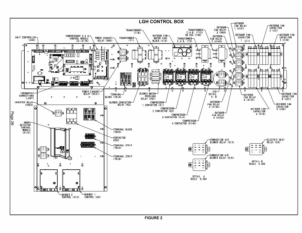
FIGURE 2
LGH CONTROL BOX
(C1)
Page 27
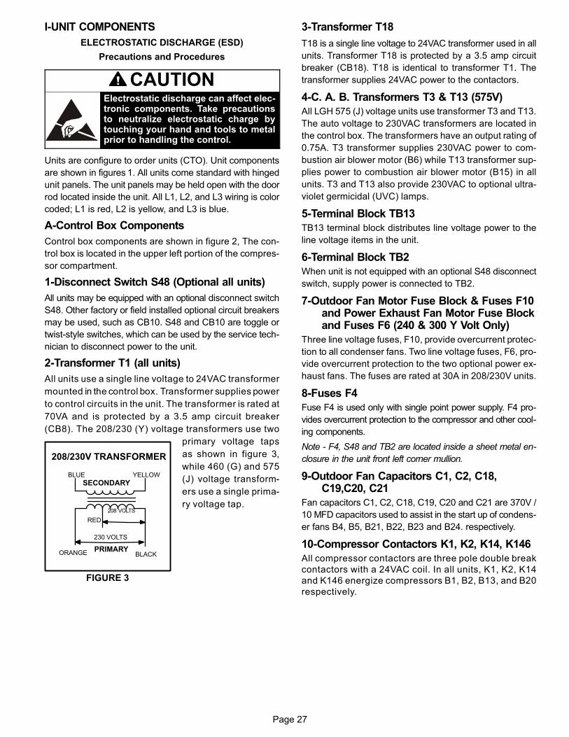
I-UNIT COMPONENTS
ELECTROSTATIC DISCHARGE (ESD)
Precautions and Procedures
CAUTIONElectrostatic discharge can affect electronic components. Take precautionsto neutralize electrostatic charge bytouching your hand and tools to metalprior to handling the control.
Units are configure to order units (CTO). Unit components
are shown in figures 1. All units come standard with hinged
unit panels. The unit panels may be held open with the door
rod located inside the unit. All L1, L2, and L3 wiring is color
coded; L1 is red, L2 is yellow, and L3 is blue.
A-Control Box Components
Control box components are shown in figure 2, The con
trol box is located in the upper left portion of the compres
sor compartment.
1-Disconnect Switch S48 (Optional all units)
All units may be equipped with an optional disconnect switch
S48. Other factory or field installed optional circuit breakers
may be used, such as CB10. S48 and CB10 are toggle or
twist-style switches, which can be used by the service tech
nician to disconnect power to the unit.
2-Transformer T1 (all units)
All units use a single line voltage to 24VAC transformer
mounted in the control box. Transformer supplies power
to control circuits in the unit. The transformer is rated at
70VA and is protected by a 3.5 amp circuit breaker
(CB8). The 208/230 (Y) voltage transformers use two
primary voltage taps
as shown in figure 3,
while 460 (G) and 575
(J) voltage transform
ers use a single prima
ry voltage tap.
3-Transformer T18
T18 is a single line voltage to 24VAC transformer used in all
units. Transformer T18 is protected by a 3.5 amp circuit
breaker (CB18). T18 is identical to transformer T1. The
transformer supplies 24VAC power to the contactors.
4-C. A. B. Transformers T3 & T13 (575V)
All LGH 575 (J) voltage units use transformer T3 and T13.
The auto voltage to 230VAC transformers are located in
the control box. The transformers have an output rating of
0.75A. T3 transformer supplies 230VAC power to com
bustion air blower motor (B6) while T13 transformer sup
plies power to combustion air blower motor (B15) in all
units. T3 and T13 also provide 230VAC to optional ultra
violet germicidal (UVC) lamps.
5-Terminal Block TB13
TB13 terminal block distributes line voltage power to the
line voltage items in the unit.
6-Terminal Block TB2
When unit is not equipped with an optional S48 disconnect
switch, supply power is connected to TB2.
7-Outdoor Fan Motor Fuse Block & Fuses F10and Power Exhaust Fan Motor Fuse Blockand Fuses F6 (240 & 300 Y Volt Only)
Three line voltage fuses, F10, provide overcurrent protec
tion to all condenser fans. Two line voltage fuses, F6, pro
vide overcurrent protection to the two optional power ex
haust fans. The fuses are rated at 30A in 208/230V units.
8-Fuses F4
Fuse F4 is used only with single point power supply. F4 pro
vides overcurrent protection to the compressor and other cool
ing components.
Note - F4, S48 and TB2 are located inside a sheet metal en
closure in the unit front left corner mullion.
9-Outdoor Fan Capacitors C1, C2, C18,C19,C20, C21
Fan capacitors C1, C2, C18, C19, C20 and C21 are 370V /
10 MFD capacitors used to assist in the start up of condens
er fans B4, B5, B21, B22, B23 and B24. respectively.
10-Compressor Contactors K1, K2, K14, K146
All compressor contactors are three pole double break
contactors with a 24VAC coil. In all units, K1, K2, K14
and K146 energize compressors B1, B2, B13, and B20
respectively.
FIGURE 3
BLUE YELLOW
ORANGE
RED
BLACK
230 VOLTS
208 VOLTS
PRIMARY
SECONDARY
208/230V TRANSFORMER

Page 28
11-Blower Contactor K3
Blower contactor K3, is a three‐pole‐double‐break contac
tor with a 24VAC coil used to energize the indoor blower
motor B3 in response to blower demand.
12-Outdoor Fan Relay K10, K68, K149, K150,
K152, K153
Outdoor fan relays K10, K68, K149, K150, K152 and K153
used in all units, are DPDT relays with a 24VAC coil. In all
units, K10 energizes fan 1 (B4), K68 energizes fan 2 (B5),
K149 energizes fan 3 (B21), K150 energizes fan 4 (B22),
K152 energizes fan 5 (B23) and K153 energizes fan 6 (B24).
13-Combustion Air Inducer Relay K13
(LGH units - first burner section)
Combustion air inducer relay K13, used in all LGH units, is a
DPDT relay with a 24VAC coil. K13 is energized by the Unit
Controller A55 after a first stage heating demand from the
thermostat. K13 remains energized throughout the heating
demand. When energized, K13 N.O. contacts close to ener
gize combustion air blower and begin a heating sequence.
Prove switch S18, located in the compressor compart
ment, closes as combustion air static pressure falls to
“prove" combustion air inducer operation. When S18
closes, the ignition controls and gas valves are energized
to begin a heating sequence.
14-Combustion Air Inducer Relay K19
(LGH units - second burner section)
Combustion air inducer relay K19, used in all LGH units, is a
DPDT relay with a 24 VAC coil. K19 is energized by A178
Unit Controller after a first stage heating demand from the
thermostat. K19 remains energized throughout the first
stage heating demand. When energized, K19 N.O. contacts
close to energize the second heat section combustion air
blower and begin second section heating sequence. Prove
switch S45, located in the compressor compartment, closes
as combustion air static pressure falls to "prove" combustion
air blower operation. When S45 closes, the second section
of the ignition control and gas valve are energized to begin
the second section heating sequence.
15-Burner Controls A3 & A12 (LGH units)
All LGH units have two burner controls. A3 controls gas
heat section one, while A12 controls gas heat section two.
The first gas heat section and the second gas heat section
burner controls are identical. Both burner controls are fac
tory set and are not adjustable. The control makes three at
tempts at ignition and then locks out the system if ignition is
not obtained after the third trial. Reset after lockout re
quires only breaking and remaking thermostat demand.
The control shuts off gas flow immediately in the event of a
gas or power failure. Upon restoration of gas and power,
the control will restart the ignition sequence and continue
until flame is established or system locks out. For a more
detailed description see the Gas Heat Components sec
tion.
16-Power Exhaust Relay K65 (PEF units)
Power exhaust relay K65 is a N.O. DPDT relay with a
24VAC coil. K65 is used in all units equipped with optional
power exhaust fans. K65 is energized by the Unit Con
troller (A55).
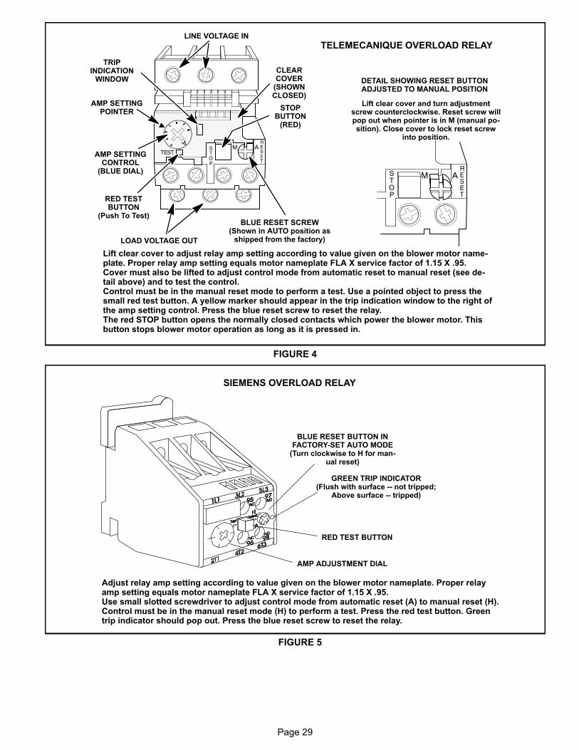
17-Blower Motor Overload Relay S42
The blower motor overload relay is used in all units
equipped with M-volt unit blower motors manufactured be
fore Dec. 19, 2010 as well as units with standard efficiency
motors of 10 HP. The relay (S42) is connected in line with
the blower motor to monitor the current flow to the motor.
When the relay senses an overload condition, a set of nor
mally closed contacts open to de-energize pin #4 in plug
P299 of the A55 Unit Controller. A55 de-energizes all out
puts. Units will be equipped with a relay manufactured by
Telemecanique figure 4 or Siemens figure 5.
18-Ultraviolet Germicidal Lamp (UVC)Transformer T49
UVC transformer T49 is used by units of all voltages except
208/230V LGH/LCH and 575V LGH which are equipped
with a UVC. The auto voltage to 230VAC transformer is in
stalled in the control box. The transformer has an output
rating of 0.75 amps. T49 transformer supplies 230VAC
power to the UVC lamp.
ELECTRIC HEAT CONTROL SECTION(30 - 120 kW electric heat only)
19-Electric Heat Relay K9
All unit equipped with optional electric heat use an electric
heat relay K9. K9 is a N.O. SPST pilot relay intended to elec
trically interlock operation of left and right side electric heat
sections. K9 is energized by the A55 Unit Controller.
20-Unit Controller A55 (all units)
The Unit Controller provides all unit control functions, unit sta
tus information, unit diagnostics, programmable parameters
and USB verification and profile sharing. Refer to the Unit Con
troller guide provided with the unit. Thermostat wires are con
nected to J297 on the Unit Controller.
21-Compressor 3 & 4 Control ModuleA178 (all units)
The compressor 3 & 4 control module A178 controls two addi
tional compressor stages. A178 includes all inputs and outputs
required for compressor and fan control, compressor stage di
agnostics, and low ambient control.
Page 29
CLEARCOVER
(SHOWNCLOSED)
STOPBUTTON
(RED)
RED TESTBUTTON
(Push To Test)
AMP SETTINGCONTROL
(BLUE DIAL)
TRIPINDICATION
WINDOW
LINE VOLTAGE IN
AMP SETTINGPOINTER
BLUE RESET SCREW(Shown in AUTO position as
shipped from the factory)LOAD VOLTAGE OUT
DETAIL SHOWING RESET BUTTONADJUSTED TO MANUAL POSITION
Lift clear cover and turn adjustmentscrew counterclockwise. Reset screw willpop out when pointer is in M (manual position). Close cover to lock reset screw
into position.
TELEMECANIQUE OVERLOAD RELAY
Lift clear cover to adjust relay amp setting according to value given on the blower motor nameplate. Proper relay amp setting equals motor nameplate FLA X service factor of 1.15 X .95.Cover must also be lifted to adjust control mode from automatic reset to manual reset (see detail above) and to test the control. Control must be in the manual reset mode to perform a test. Use a pointed object to press thesmall red test button. A yellow marker should appear in the trip indication window to the right ofthe amp setting control. Press the blue reset screw to reset the relay.The red STOP button opens the normally closed contacts which power the blower motor. Thisbutton stops blower motor operation as long as it is pressed in.
FIGURE 4
SIEMENS OVERLOAD RELAY
Adjust relay amp setting according to value given on the blower motor nameplate. Proper relayamp setting equals motor nameplate FLA X service factor of 1.15 X .95.Use small slotted screwdriver to adjust control mode from automatic reset (A) to manual reset (H). Control must be in the manual reset mode (H) to perform a test. Press the red test button. Greentrip indicator should pop out. Press the blue reset screw to reset the relay.
BLUE RESET BUTTON INFACTORY‐SET AUTO MODE
(Turn clockwise to H for manual reset)
GREEN TRIP INDICATOR(Flush with surface -- not tripped;
Above surface -- tripped)
AMP ADJUSTMENT DIAL
RED TEST BUTTON
FIGURE 5
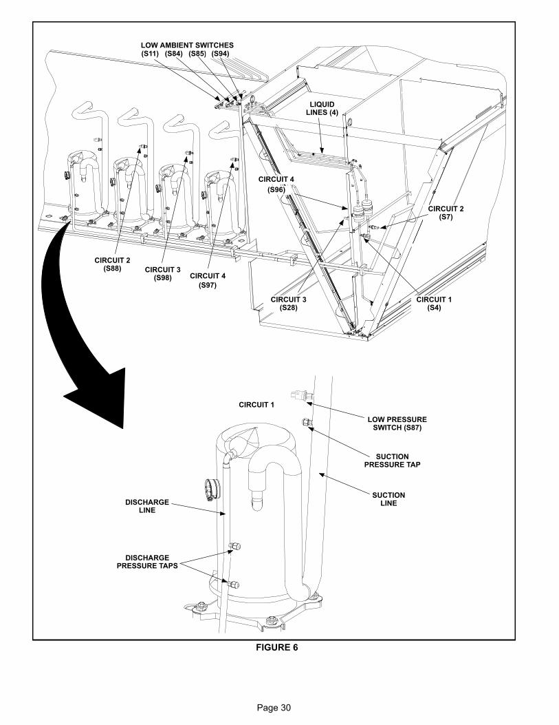
Page 30
SUCTIONLINEDISCHARGE
LINE
DISCHARGEPRESSURE TAPS
LOW PRESSURESWITCH (S87)
SUCTIONPRESSURE TAP
CIRCUIT 1
(S96)
CIRCUIT 4
(S97)
CIRCUIT 4CIRCUIT 3
(S98)
CIRCUIT 3(S28)
CIRCUIT 2(S88)
CIRCUIT 2(S7)
CIRCUIT 1(S4)
(S11) (S84) (S85) (S94)LOW AMBIENT SWITCHES
LIQUIDLINES (4)
FIGURE 6
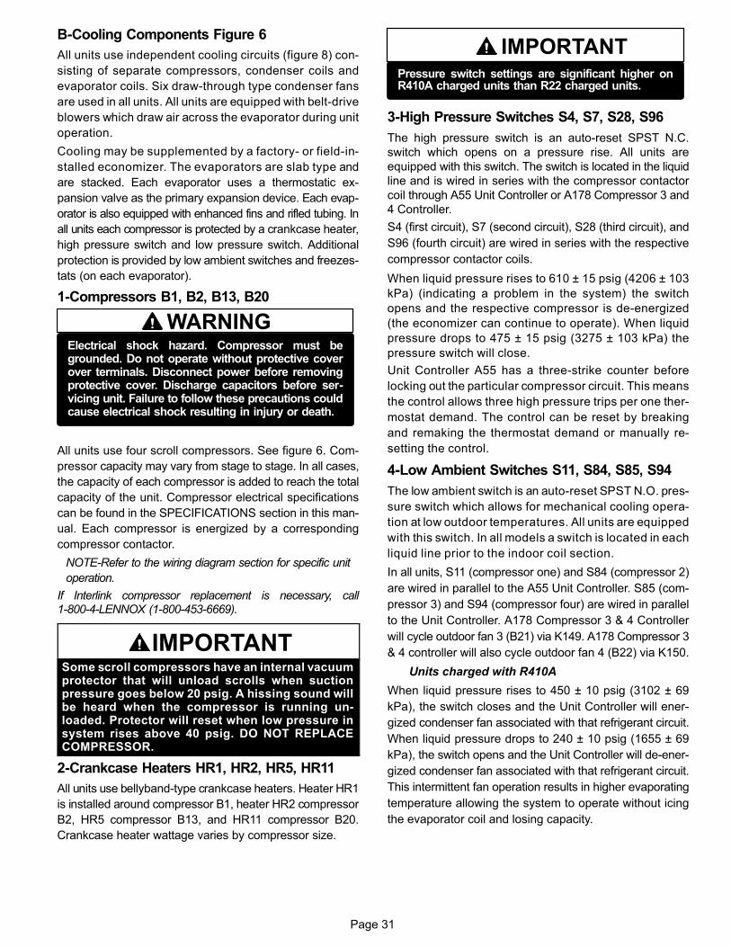
Page 31
B-Cooling Components Figure 6
All units use independent cooling circuits (figure 8) con
sisting of separate compressors, condenser coils and
evaporator coils. Six draw-through type condenser fans
are used in all units. All units are equipped with belt‐drive
blowers which draw air across the evaporator during unit
operation.
Cooling may be supplemented by a factory‐ or field‐in
stalled economizer. The evaporators are slab type and
are stacked. Each evaporator uses a thermostatic ex
pansion valve as the primary expansion device. Each evap
orator is also equipped with enhanced fins and rifled tubing. In
all units each compressor is protected by a crankcase heater,
high pressure switch and low pressure switch. Additional
protection is provided by low ambient switches and freezes
tats (on each evaporator).
1-Compressors B1, B2, B13, B20
WARNINGElectrical shock hazard. Compressor must begrounded. Do not operate without protective coverover terminals. Disconnect power before removingprotective cover. Discharge capacitors before servicing unit. Failure to follow these precautions couldcause electrical shock resulting in injury or death.
All units use four scroll compressors. See figure 6. Com
pressor capacity may vary from stage to stage. In all cases,
the capacity of each compressor is added to reach the total
capacity of the unit. Compressor electrical specifications
can be found in the SPECIFICATIONS section in this man
ual. Each compressor is energized by a corresponding
compressor contactor.
NOTE-Refer to the wiring diagram section for specific unit
operation.
If Interlink compressor replacement is necessary, call1-800-4-LENNOX (1-800-453-6669).
IMPORTANTSome scroll compressors have an internal vacuumprotector that will unload scrolls when suctionpressure goes below 20 psig. A hissing sound willbe heard when the compressor is running unloaded. Protector will reset when low pressure insystem rises above 40 psig. DO NOT REPLACECOMPRESSOR.
2-Crankcase Heaters HR1, HR2, HR5, HR11
All units use bellyband-type crankcase heaters. Heater HR1
is installed around compressor B1, heater HR2 compressor
B2, HR5 compressor B13, and HR11 compressor B20.
Crankcase heater wattage varies by compressor size.
IMPORTANTPressure switch settings are significant higher onR410A charged units than R22 charged units.
3-High Pressure Switches S4, S7, S28, S96
The high pressure switch is an auto‐reset SPST N.C.
switch which opens on a pressure rise. All units are
equipped with this switch. The switch is located in the liquid
line and is wired in series with the compressor contactor
coil through A55 Unit Controller or A178 Compressor 3 and
4 Controller.
S4 (first circuit), S7 (second circuit), S28 (third circuit), and
S96 (fourth circuit) are wired in series with the respective
compressor contactor coils.
When liquid pressure rises to 610 ± 15 psig (4206 ± 103
kPa) (indicating a problem in the system) the switch
opens and the respective compressor is de-energized
(the economizer can continue to operate). When liquid
pressure drops to 475 ± 15 psig (3275 ± 103 kPa) the
pressure switch will close.
Unit Controller A55 has a three-strike counter before
locking out the particular compressor circuit. This means
the control allows three high pressure trips per one ther
mostat demand. The control can be reset by breaking
and remaking the thermostat demand or manually re
setting the control.
4-Low Ambient Switches S11, S84, S85, S94
The low ambient switch is an auto‐reset SPST N.O. pres
sure switch which allows for mechanical cooling opera
tion at low outdoor temperatures. All units are equipped
with this switch. In all models a switch is located in each
liquid line prior to the indoor coil section.
In all units, S11 (compressor one) and S84 (compressor 2)
are wired in parallel to the A55 Unit Controller. S85 (com
pressor 3) and S94 (compressor four) are wired in parallel
to the Unit Controller. A178 Compressor 3 & 4 Controller
will cycle outdoor fan 3 (B21) via K149. A178 Compressor 3
& 4 controller will also cycle outdoor fan 4 (B22) via K150.
Units charged with R410A
When liquid pressure rises to 450 ± 10 psig (3102 ± 69
kPa), the switch closes and the Unit Controller will ener
gized condenser fan associated with that refrigerant circuit.
When liquid pressure drops to 240 ± 10 psig (1655 ± 69
kPa), the switch opens and the Unit Controller will de-ener
gized condenser fan associated with that refrigerant circuit.
This intermittent fan operation results in higher evaporating
temperature allowing the system to operate without icing
the evaporator coil and losing capacity.
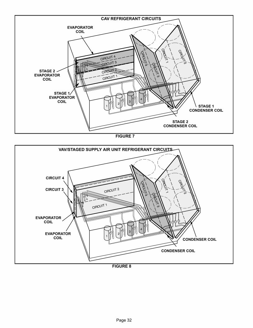
Page 32
EVAPORATORCOIL
STAGE 1CONDENSER COIL
FIGURE 7
STAGE 2CONDENSER COIL
STAGE 1EVAPORATOR
COIL
STAGE 2EVAPORATOR
COIL
CAV REFRIGERANT CIRCUITS
VAV/STAGED SUPPLY AIR UNIT REFRIGERANT CIRCUITS
CONDENSER COIL
FIGURE 8
CONDENSER COIL
EVAPORATORCOIL
EVAPORATORCOIL
CIRCUIT 3
CIRCUIT 4
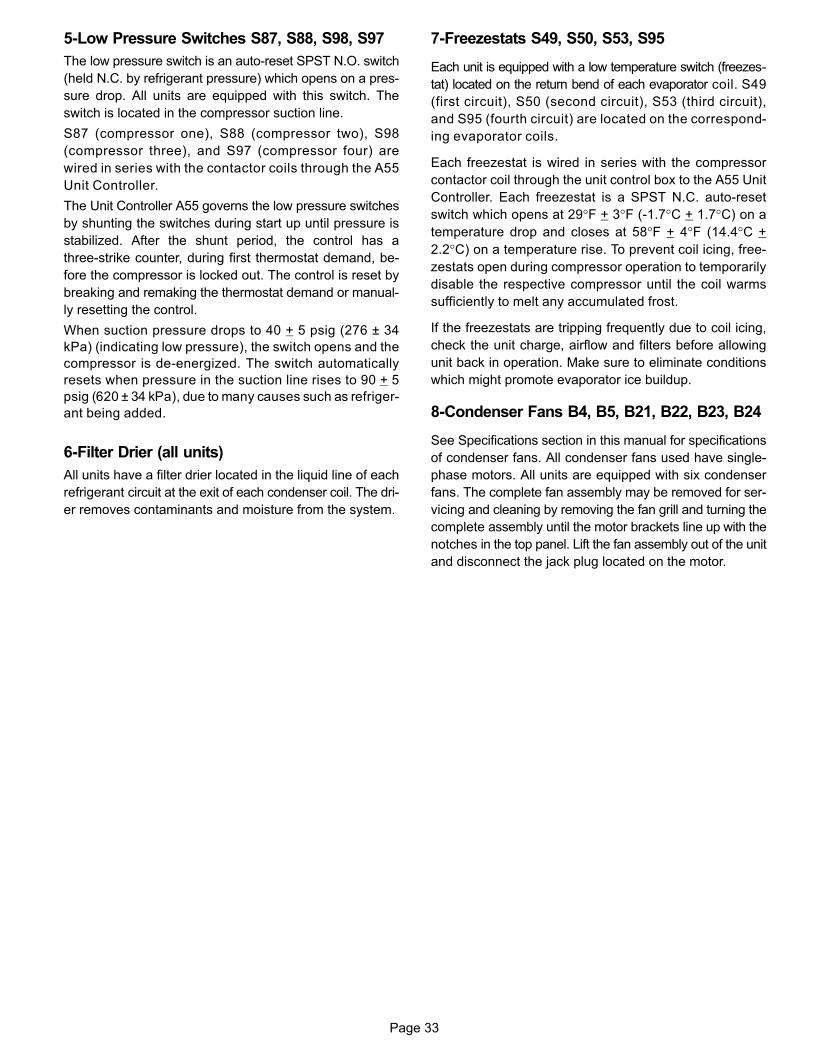
Page 33
5-Low Pressure Switches S87, S88, S98, S97
The low pressure switch is an auto‐reset SPST N.O. switch
(held N.C. by refrigerant pressure) which opens on a pres
sure drop. All units are equipped with this switch. The
switch is located in the compressor suction line.
S87 (compressor one), S88 (compressor two), S98
(compressor three), and S97 (compressor four) are
wired in series with the contactor coils through the A55
Unit Controller.
The Unit Controller A55 governs the low pressure switches
by shunting the switches during start up until pressure is
stabilized. After the shunt period, the control has a
three‐strike counter, during first thermostat demand, be
fore the compressor is locked out. The control is reset by
breaking and remaking the thermostat demand or manual
ly resetting the control.
When suction pressure drops to 40 + 5 psig (276 ± 34
kPa) (indicating low pressure), the switch opens and the
compressor is de-energized. The switch automatically
resets when pressure in the suction line rises to 90 + 5
psig (620 ± 34 kPa), due to many causes such as refriger
ant being added.
6-Filter Drier (all units)
All units have a filter drier located in the liquid line of each
refrigerant circuit at the exit of each condenser coil. The dri
er removes contaminants and moisture from the system.
7-Freezestats S49, S50, S53, S95
Each unit is equipped with a low temperature switch (freezes
tat) located on the return bend of each evaporator coil. S49
(first circuit), S50 (second circuit), S53 (third circuit),
and S95 (fourth circuit) are located on the correspond
ing evaporator coils.
Each freezestat is wired in series with the compressor
contactor coil through the unit control box to the A55 Unit
Controller. Each freezestat is a SPST N.C. auto-reset
switch which opens at 29°F + 3°F (‐1.7°C + 1.7°C) on a
temperature drop and closes at 58°F + 4°F (14.4°C +
2.2°C) on a temperature rise. To prevent coil icing, free
zestats open during compressor operation to temporarily
disable the respective compressor until the coil warms
sufficiently to melt any accumulated frost.
If the freezestats are tripping frequently due to coil icing,
check the unit charge, airflow and filters before allowing
unit back in operation. Make sure to eliminate conditions
which might promote evaporator ice buildup.
8-Condenser Fans B4, B5, B21, B22, B23, B24
See Specifications section in this manual for specifications
of condenser fans. All condenser fans used have single-
phase motors. All units are equipped with six condenser
fans. The complete fan assembly may be removed for ser
vicing and cleaning by removing the fan grill and turning the
complete assembly until the motor brackets line up with the
notches in the top panel. Lift the fan assembly out of the unit
and disconnect the jack plug located on the motor.

Page 34
C-Blower Compartment
The blower compartment in all units is located between the
evaporator coil and the compressor / control section on the
opposite side of the condenser coil. The blower assembly
is accessed by disconnecting the blower motor wiring (and
all other plugs) and removing the screws on either side of
the sliding base. The base pulls out as shown in figure 9.
1-Blower Wheels (all units)
All units have two 18 in. x 15 in. (457 mm x 381 mm) blower
wheels. Both wheels are driven by one motor.
2-Indoor Blower Motor B3 (all units)
All units use three‐phase single‐speed blower motors. CFM
adjustments are made by adjusting the motor pulley (sheave).
Motors are equipped with sealed ball bearings. All motor spec
ifications are listed in the SPECIFICATIONS section in this
manual. Units may be equipped with motors manufactured by
various manufacturers, therefore electrical FLA and LRA
specifications will vary. See unit rating plate for information
specific to your unit.
IMPORTANTThree phase scroll compressors must be phased sequentially for correct compressor and blower rotation. Follow “COOLING START-UP" section of installation instructions to ensure proper compressor andblower operation.
A-Blower Operation
NOTE-The following is a generalized procedure and does
not apply to all thermostat control systems.
1- Blower operation is dependent on the thermostat con
trol system option that has been installed in the units.
Refer to operation sequence of the control system in
stalled for detailed descriptions of blower operation.
2- Generally, blower operation is set at the thermostat fan
switch. With the fan switch in "ON" position and the
OCP input is "ON", the blower operates continuously.
With the fan switch in "AUTO" position, the blower cy
cles with demand.
3- In most cases, the blower and entire unit will be off
when the system switch is in the "OFF" position. The
only exception is immediately after a heating demand
when the blower control keeps the blower on until all
heat is extracted from the heat exchanger.
B-Blower Access
1- Disconnect wiring connected to heating limit switches
and mixed air sensor in units with an economizer. Dis
connect blower harness at K3 contactor (CAV) or A96
inverter (VAV/Staged). Failure to do so could damage
harness or components.
2- Remove screws on either side of blower assembly slid
ing base. See figure 9.
3- Pull base toward outside of unit.
C-Determining Unit CFM
1- The following measurements must be made with a dry
indoor coil. Run blower without a cooling demand.
Measure the indoor blower shaft RPM. Air filters must
be in place when measurements are taken.
2- With all access panels in place, measure static pres
sure external to unit (from supply to return). Blower
performance data is based on static pressure readings
taken in locations shown in figure 10.
Note - Static pressure readings can vary if not taken where
shown.
3- Referring to blower tables in the front of this manual,
use static pressure and RPM readings to determine
unit CFM. Use table "FACTORY INSTALLED OP
TIONS/FIELD INSTALLED ACCESSORY AIR RE
SISTANCE" when installing units with any of the op
tional accessories listed.

Page 35
BLOWER ASSEMBLY
TO INCREASE BELT TENSION
1-Loosen four screws securing blower motor tosliding base.
2-Turn adjusting screw to the left, or counterclockwise, to move the motor downward andtighten the belt.
3-Tighten four screws.
TO INCREASE CFMLOOSEN ALLEN SCREW &
TURN PULLEY CLOCKWISE
TO DECREASE CFMTURN PULLEY
COUNTERCLOCKWISE
FIGURE 9
LOOSEN SCREWSTO ADJUST BELT
TENSIONBLOWERMOTOR
REMOVE SCREWS TO SLIDEBLOWER ASSEMBLY OUT OF UNIT
LOOSEN SCREWS TOADJUST BELT TENSION
PULLEY
ALLENSCREW
BELT TENSIONADJUSTING SCREWS
BLOWERASSEMBLY
SLIDING BASE
PULLEY
MOTOR ALLENSCREW
SIDE VIEW
FIGURE 10
LOCATION OF STATIC PRESSURE READINGS
SUPPLY AIRREADING LO
CATION
SUPPLYRE
TURN
INSTALLATIONS WITH DUCTWORK
SUPPLY RETURN
INSTALLATIONS WITH CEILING DIFFUSERS
MAINDUCT RUN
FIRST BRANCHOFF OF MAIN RUN
DIFFUSER
ROOFTOP UNIT ROOFTOP UNIT
SUPPLY AIRREADING LO
CATION
RETURN AIRREADING LOCATION
RETURN AIRREADING LO
CATION
TABLE 1MINIMUM AND MAXIMUM PULLEY ADJUSTMENT
Belt Minimum Turns Open Maximum Turns Open
A Section No minimum 5
B Section 1* 6
*No minimum number of turns open when B belt is used onpulleys 6" O.D. or larger.
4- Constant Air Volume (CAV) Supply Air Blowers -
The blower RPM can be adjusted at the motor pulley.
Loosen Allen screw and turn adjustable pulley clock
wise to increase CFM. Turn counterclockwise to de
crease CFM. See figure 9. Do not exceed minimum
and maximum number of pulley turns as shown in ta
ble 1.
5- Variable Air Volume (VAV) Supply Air Blowers -
Adjust motor pulley to set-up maximum blower RPM
and CFM at 60 HZ. Do not exceed brake horse power
of the motor. Loosen Allen screw and turn adjustable
pulley clockwise to increase CFM. Turn counterclock
wise to decrease CFM. See figure 9. Do not exceed
minimum and maximum number of pulley turns as
shown in table 1.
After setting up the maximum CFM at 60HZ, the sup
ply CFM can be adjusted at the Unit Controller or by
using optional software. This value is adjusted
through unit Parameter 390.
In default mode, the Unit Controller is set to drive the
blower to maximum CFM output (100% or 60Hz). To
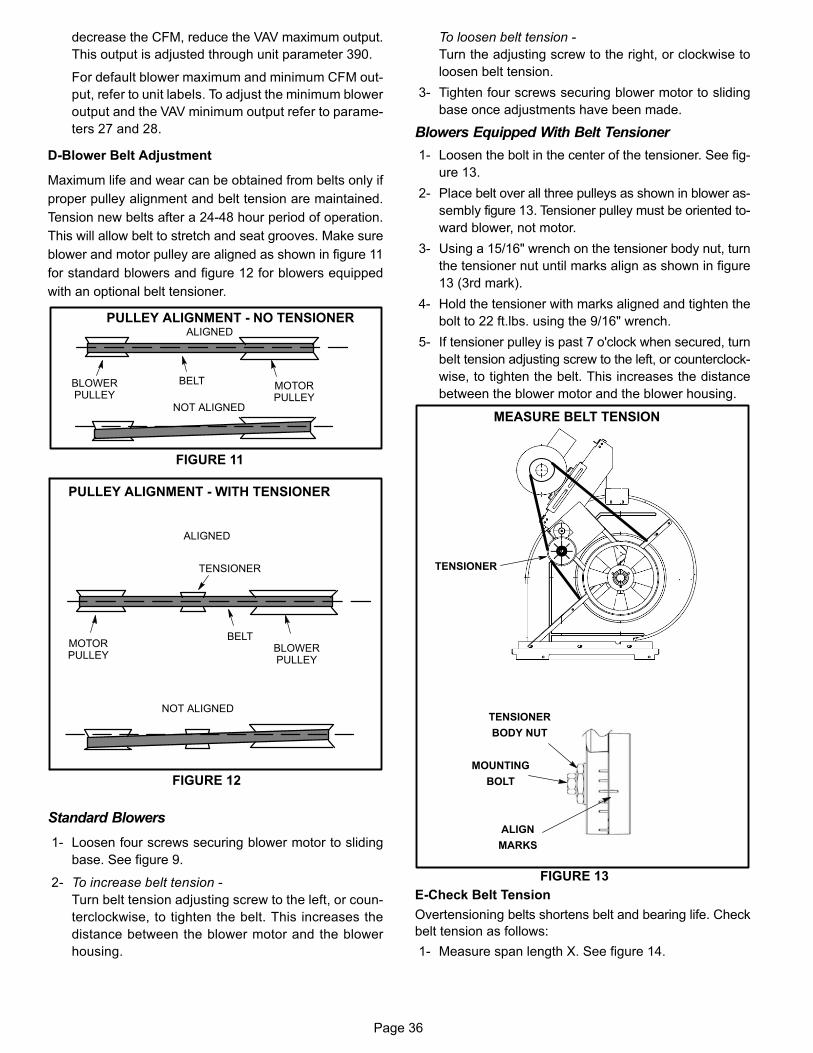
Page 36
decrease the CFM, reduce the VAV maximum output.
This output is adjusted through unit parameter 390.
For default blower maximum and minimum CFM out
put, refer to unit labels. To adjust the minimum blower
output and the VAV minimum output refer to parame
ters 27 and 28.
D-Blower Belt Adjustment
Maximum life and wear can be obtained from belts only if
proper pulley alignment and belt tension are maintained.
Tension new belts after a 24-48 hour period of operation.
This will allow belt to stretch and seat grooves. Make sure
blower and motor pulley are aligned as shown in figure 11
for standard blowers and figure 12 for blowers equipped
with an optional belt tensioner.
FIGURE 11
PULLEY ALIGNMENT - NO TENSIONER
BELTBLOWERPULLEY
MOTORPULLEY
NOT ALIGNED
ALIGNED
BELTBLOWERPULLEY
MOTORPULLEY
NOT ALIGNED
ALIGNED
TENSIONER
PULLEY ALIGNMENT - WITH TENSIONER
FIGURE 12
Standard Blowers
1- Loosen four screws securing blower motor to sliding
base. See figure 9.
2- To increase belt tension -
Turn belt tension adjusting screw to the left, or coun
terclockwise, to tighten the belt. This increases the
distance between the blower motor and the blower
housing.
To loosen belt tension -
Turn the adjusting screw to the right, or clockwise to
loosen belt tension.
3- Tighten four screws securing blower motor to sliding
base once adjustments have been made.
Blowers Equipped With Belt Tensioner
1- Loosen the bolt in the center of the tensioner. See fig
ure 13.
2- Place belt over all three pulleys as shown in blower as
sembly figure 13. Tensioner pulley must be oriented to
ward blower, not motor.
3- Using a 15/16" wrench on the tensioner body nut, turn
the tensioner nut until marks align as shown in figure
13 (3rd mark).
4- Hold the tensioner with marks aligned and tighten the
bolt to 22 ft.lbs. using the 9/16" wrench.
5- If tensioner pulley is past 7 o'clock when secured, turn
belt tension adjusting screw to the left, or counterclock
wise, to tighten the belt. This increases the distance
between the blower motor and the blower housing.
MEASURE BELT TENSION
FIGURE 13
TENSIONER
TENSIONER
BODY NUT
MOUNTING
BOLT
ALIGN
MARKS
E-Check Belt Tension
Overtensioning belts shortens belt and bearing life. Check
belt tension as follows:
1- Measure span length X. See figure 14.

Page 37
MEASURE BELT TENSION
FIGURE 14
DEFLECTION 1/64" PER INCH OF SPANOR 1.5mm PER 100mm OF SPAN
FORCE
2- Apply perpendicular force to center of span (X) with
enough pressure to deflect belt 1/64" for every inch of
span length or 1.5mm per 100mm of span length.
Example: Deflection distance of a 40" span would be
40/64" or 5/8".
Example: Deflection distance of a 400mm span would
be 6mm.
3- Measure belt deflection force. For a used belt, the de
flection force should be 5 lbs. (35kPa). A new belt de
flection force should be 7 lbs. (48kPa). A force below
these values indicates an undertensioned belt. A force
above these values indicates an overtensioned belt.
F-Furnished Blower Drives
For field furnished blower drives, see BLOWER DATA (ta
ble of contents) for CFM and RPM. The BLOWER DATA
section also has tables for drive numbers and manufactur
er's model numbers. Reference the manufacturer's model
numbers in table 2.
TABLE 2MANUFACTURER'S NUMBERS (60 HZ)
DriveNo.
DRIVE COMPONENTS
ADJUSTABLE SHEAVE FIXED SHEAVE BELTS BELTS W/ TENSIONER SPLIT BUSHING
Supplier No.OEM Part
No.Supplier
No.OEM Part
No.Supplier
No.OEM Part
No.Supplier
No.OEM Part
No. Supplier No.OEM Part
No.
1 1VP71x1-3/8 100239-06 BK140H 100788-13 BX78 100245-44 BX77 100245-43 H - 1-7/16 49M6201
2 1VP71x1-1/8 100239-06 BK120H 100788-07 BX75 31K9801 BX73 100245-41 H - 1-7/16 49M6201
3 1VP65x1-3/8 78M7101 BK130H 100788-08 BX75 31K9801 BX74 100245-42 H - 1-7/16 49M6201
4 1VP60x1-3/8 78L5501 BK110H 100788-06 BX71 31K9701 BX71 31K9701 H - 1-7/16 49M6201
5 1VP56x1-1/8 P-8-1492 BK120H 100788-07 BX71 31K9701 BX71 31K9701 H - 1-7/16 49M6201
6 1VP60x1-1/8 41C1301 BK110H 100788-06 BX70 31K9601 BX70 31K9601 H - 1-7/16 49M6201
7 1VP50x1-1/8 P-8-1977 BK120H 100788-07 BX70 31K9601 BX70 31K9601 H - 1-7/16 49M6201
8 1VP44x1-1/8 36C0701 BK120H 100788-07 BX70 31K9601 BX70 31K9601 H - 1-7/16 49M6201
9 1VP44x1-1/8 36C0701 BK140H 100788-13 BX73 100245-41 BX72 100245-14 H - 1-7/16 49M6201

Page 38
D-GAS HEAT COMPONENTS (LGH Units) Units are available in 260,000 Btuh (76.2 kW) standard
gas heat, 360,000 Btuh (105.5 kW) medium gas heat
and 480,000 Btuh (140.6 kW) high gas heat sizes. See
unit nameplate for capacities. All units are equipped
with two identical gas heat sections (gas heat section
one and gas heat section two). Flexible pipe will feed
supply gas to both sections. If for service the flexible
connection must broken, hand tighten, then using a
wrench turn additional 1/4 turn for metal to metal seal
(do not over tighten).
NOTE-Do not use thread sealing compound on flex pipe
flare connections.
1-Control Box Components A3, A12, A55, A178, T3, T13, K13 and K19
The main control box (see figure 2) houses the burner
controls A3 and A12, Unit Controller A55 and A178, com
bustion air inducer transformers T3 and T13, combustion
air inducer relay K13, and second heat section relay K19.
For a description of the components see section I‐A. A
more detailed description of burner controls A3 and A12
is given below.
Burner Ignition Control A3 and A12
The ignition controls are located in the control box and are
manufactured by Utec. See table 3 for LED codes.
The ignition control provides three main functions: gas
valve control, ignition, and flame sensing.
On a heating demand, the ignition control checks for a
closed limit switch. Once this check is complete and
conditions are correct, the ignition control then allows
30 seconds for the combustion air inducer to vent ex
haust gases from the burners. When the combustion air
inducer is purging the exhaust gases, the combustion
air prove switch closes proving that the combustion air
inducer is operating before allowing the ignition control
to energize. When the combustion air prove switch is
closed and the delay is over, the ignition control acti
vates the gas valve(s), the spark electrode and the
flame sensing electrode. At the start of the ignition se
quence, the adjustable 40 second (default) indoor blow
er delay period begins. Sparking stops immediately af
ter flame is sensed or at the end of the 8 second trial for
ignition. If flame is not sensed, A3 or A12 will wait 5 min
utes before attempting ignition again. If the third trial
fails, A3 or A12 will lock-out for one hour. The A55
counts this as a first strike. After the first lock-out hour
elapses, A3 or A12 will attempt ignition three more
times. If flame is still not sensed, A3 or A12 will lock-out
for the second hour. A55 counts this as the second
strike. After the second lockout hour, A3 or A12 will at
tempt ignition three more times. If ignition fails, A55 con
siders this the third strike and will lock-out unit opera
tion. Service relay contacts close and alarm 59 or 69 is
displayed. The unit will remain in lock-out until:
1-A55 is reset
or
2-The alarm condition is cleared AND the alarm sta-
tus is read through the SBUS command.
Once the flame is sensed, the ignition control then pro
ceeds to “steady state” mode where all inputs are moni
tored to ensure the limit switch, roll-out switch and prove
switch are closed as well as flame is present. When the
heat call is satisfied the gas valve and combustion air in
ducer are de-energized. An adjustable 120-second (de
fault) blower off delay begins.
TABLE 3
UTEC
LEDFlashes
Indicates
Steady Off No power or control hardware fault.
Steady On Power applied. Control OK.
3 Flashes Ignition lockout from too many trials.
4 FlashesIgnition lockout from too many flame losses within single call for heat.
5 Flashes Control hardware fault detected.
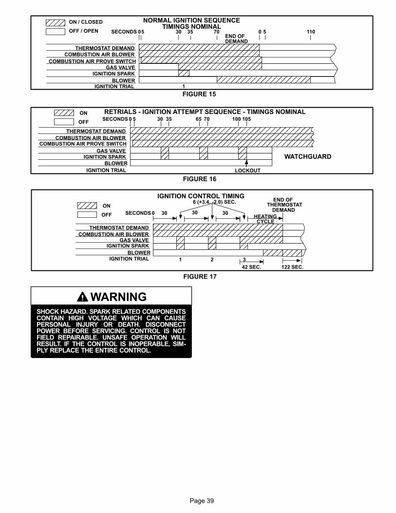
Page 39
ÉÉÉÉÉÉÉÉÉÉÉÉÉÉÉÉÉÉÉÉÉÉÉÉÉÉÉÉ
ÉÉÉ
ÉÉÉÉÉÉÉÉÉÉÉÉÉÉÉÉÉÉÉÉÉÉ ÉÉÉÉÉÉÉÉÉÉÉ
ÉÉÉÉÉÉÉÉÉÉÉ
NORMAL IGNITION SEQUENCETIMINGS NOMINAL
THERMOSTAT DEMAND
COMBUSTION AIR BLOWER
GAS VALVE
IGNITION SPARK
BLOWERIGNITION TRIAL
SECONDS 0 30 35 0 110
ON / CLOSED
OFF / OPENEND OFDEMAND
1
ÉÉÉÉÉÉÉÉÉÉÉÉÉÉÉÉÉÉÉÉÉÉÉÉÉÉ
COMBUSTION AIR PROVE SWITCH
5 570
FIGURE 15
FIGURE 16
RETRIALS - IGNITION ATTEMPT SEQUENCE - TIMINGS NOMINALÉÉÉ
ÉÉÉÉ
THERMOSTAT DEMAND
COMBUSTION AIR BLOWER
GAS VALVEIGNITION SPARK
BLOWER
IGNITION TRIAL
SECONDS 0 30 35 70ON
OFF
ÉÉÉÉÉÉÉÉÉÉÉÉÉÉÉÉÉÉÉÉÉÉÉÉÉÉÉÉÉÉÉÉÉÉÉÉÉÉ
ÉÉÉÉÉÉÉÉÉÉÉÉÉÉÉÉÉÉÉÉÉÉÉÉÉÉÉÉÉÉÉÉÉÉÉÉÉÉ
ÉÉ
ÉÉÉÉÉÉÉÉ
ÉÉ
65 100 105
WATCHGUARD
LOCKOUT
COMBUSTION AIR PROVE SWITCHÉÉÉÉÉÉÉÉÉÉÉÉÉÉÉÉÉÉÉ
5
FIGURE 17
ÉÉÉ
ÉÉÉÉÉÉÉÉÉÉÉÉÉÉÉÉÉÉÉÉÉÉÉÉÉÉÉÉÉÉÉÉÉ
ÉÉÉÉÉÉÉÉ
THERMOSTAT DEMAND
COMBUSTION AIR BLOWERGAS VALVE
IGNITION SPARK
BLOWERIGNITION TRIAL
SECONDS 0 30
ON
OFF
IGNITION CONTROL TIMING
ÉÉÉÉ
ÉÉÉÉ ÉÉ
ÉÉ
ÉÉÉÉ É
É ÉÉÉ
30 30HEATING
CYCLE
6 (+3.4, -2.0) SEC. END OFTHERMOSTAT
DEMAND
1 2 3
42 SEC. 122 SEC.
WARNINGSHOCK HAZARD. SPARK RELATED COMPONENTSCONTAIN HIGH VOLTAGE WHICH CAN CAUSEPERSONAL INJURY OR DEATH. DISCONNECTPOWER BEFORE SERVICING. CONTROL IS NOTFIELD REPAIRABLE. UNSAFE OPERATION WILLRESULT. IF THE CONTROL IS INOPERABLE, SIMPLY REPLACE THE ENTIRE CONTROL.
Page 40
2-Heat Exchanger (Figures 18 and 19)
Two Styles used
The LGH units use aluminized steel inshot burners with
matching tubular aluminized steel (stainless steel is an
option) heat exchangers and two‐stage redundant gas
valves. LGH uses two eleven-tube/burners for high heat,
two nine-tube burners for medium heat (if applicable, see
unit nameplate) and two six-tube/burners for standard
heat. Each burner uses a burner venturi to mix gas and air
for proper combustion. Combustion takes place at each
tube entrance. As hot combustion gases are drawn up
ward through each tube by the combustion air blower, ex
haust gases are drawn out the top and fresh air/gas mix
ture is drawn in at the bottom. Heat is transferred to the air
stream from all surfaces of the heat exchanger tubes. The
supply air blowers, controlled by the Unit Controller A55,
force air across all surfaces of the tubes to extract the heat
of combustion. The shape of the tubes ensures maximum
heat transfer.
The gas valves accomplish staging by providing more or less
gas to the burners as required by heating demand.
3-Burner Assembly (Figure 20)
The burners are controlled by the spark electrode, flame
sensing electrode, gas valve and combustion air blower.
The spark electrode, flame sensing electrode and gas
valve are directly controlled by ignition control. Ignition con
trol and combustion air inducer is controlled by Unit Con
troller A55.
Burners
All units use inshot burners (see figures 20 and 21). Burn
ers are factory set and do not require adjustment. A peep
hole with cover is furnished in the heating access
panel for flame viewing. Always operate the unit with
the access panel in place. Burners can be removed
individually for service. Burner maintenance and
service is detailed in the SERVICE CHECKS sec
tions of this manual.
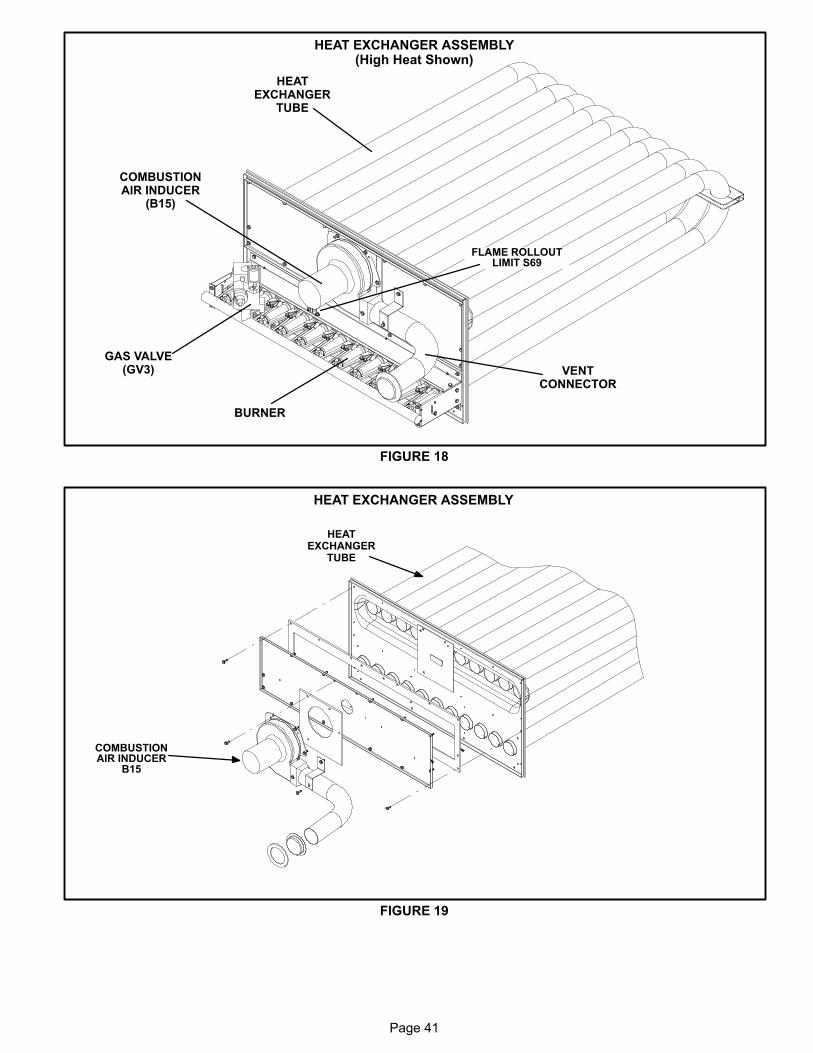
Page 41
FIGURE 18
BURNER
COMBUSTIONAIR INDUCER
(B15)
VENTCONNECTOR
GAS VALVE(GV3)
HEATEXCHANGER
TUBE
HEAT EXCHANGER ASSEMBLY(High Heat Shown)
FLAME ROLLOUTLIMIT S69
FIGURE 19
COMBUSTIONAIR INDUCER
B15
HEATEXCHANGER
TUBE
HEAT EXCHANGER ASSEMBLY
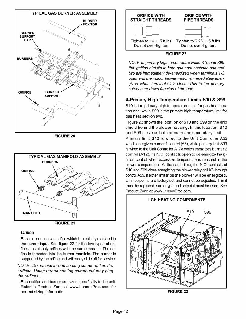
Page 42
FIGURE 20
TYPICAL GAS BURNER ASSEMBLY
BURNERS
ORIFICE BURNERSUPPORT
BURNERBOX TOP
BURNERSUPPORT
CAP
FIGURE 21
TYPICAL GAS MANIFOLD ASSEMBLY
BURNERS
MANIFOLD
ORIFICE
Orifice
Each burner uses an orifice which is precisely matched to
the burner input. See figure 22 for the two types of ori
fices; install only orifices with the same threads. The ori
fice is threaded into the burner manifold. The burner is
supported by the orifice and will easily slide off for service.
NOTE - Do not use thread sealing compound on the
orifices. Using thread sealing compound may plug
the orifices.
Each orifice and burner are sized specifically to the unit.
Refer to Product Zone at www.LennoxPros.com for
correct sizing information.
ORIFICE WITHPIPE THREADS
Tighten to 6.25 + .5 ft.lbs.Do not over-tighten.
Tighten to 14 + .5 ft/lbs Do not over-tighten.
ORIFICE WITHSTRAIGHT THREADS
FIGURE 22
NOTE-In primary high temperature limits S10 and S99
the ignition circuits in both gas heat sections one and
two are immediately de-energized when terminals 1-3
open and the indoor blower motor is immediately ener
gized when terminals 1-2 close. This is the primary
safety shut-down function of the unit.
4-Primary High Temperature Limits S10 & S99
S10 is the primary high temperature limit for gas heat sec
tion one, while S99 is the primary high temperature limit for
gas heat section two.
Figure 23 shows the location of S10 and S99 on the drip
shield behind the blower housing. In this location, S10
and S99 serve as both primary and secondary limit.
Primary limit S10 is wired to the Unit Controller A55
which energizes burner 1 control (A3), while primary limit S99
is wired to the Unit Controller A178 which energizes burner 2
control (A12). Its N.C. contacts open to de-energize the ig
nition control when excessive temperature is reached in the
blower compartment. At the same time, the N.O. contacts of
S10 and S99 close energizing the blower relay coil K3 through
control A55. If either limit trips the blower will be energized.
Limit setpoints are factory-set and cannot be adjusted. If limit
must be replaced, same type and setpoint must be used. See
Product Zone at www.LennoxPros.com.
LGH HEATING COMPONENTS
FIGURE 23
S10 S99
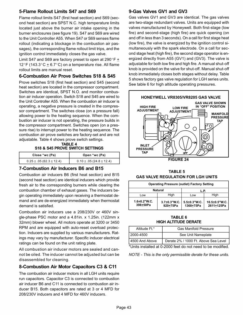
Page 43
5-Flame Rollout Limits S47 and S69
Flame rollout limits S47 (first heat section) and S69 (sec
ond heat section) are SPST N.C. high temperature limits
located just above the burner air intake opening in the
burner enclosures (see figure 19). S47 and S69 are wired
to the Unit Controller A55. When S47 or S69 senses flame
rollout (indicating a blockage in the combustion air pas
sages), the corresponding flame rollout limit trips, and the
ignition control immediately closes the gas valve.
Limit S47 and S69 are factory preset to open at 290�F +
12�F (143.3�C + 6.7�C) on a temperature rise. All flame
rollout limits are manual reset.
6-Combustion Air Prove Switches S18 & S45
Prove switches S18 (first heat section) and S45 (second
heat section) are located in the compressor compartment.
Switches are identical, SPST N.O. and monitor combus
tion air inducer operation. Switch S18 and S45 are wired to
the Unit Controller A55. When the combustion air inducer is
operating, a negative pressure is created in the compres
sor compartment. The switches close (on a pressure fall)
allowing power to the heating sequence. When the com
bustion air inducer is not operating, the pressure builds in
the compressor compartment. Switches open (on a pres
sure rise) to interrupt power to the heating sequence. The
combustion air prove switches are factory-set and are not
adjustable. Table 4 shows prove switch settings.
TABLE 4S18 & S45 PROVE SWITCH SETTINGS
Close “wc (Pa) Open “wc (Pa)
0.25 + .05 (62.3 + 12.4) 0.10 + .05 (24.8 + 12.4)
7-Combustion Air Inducers B6 and B15
Combustion air inducers B6 (first heat section) and B15
(second heat section) are identical inducers which provide
fresh air to the corresponding burners while clearing the
combustion chamber of exhaust gases. The inducers be
gin operating immediately upon receiving a thermostat de
mand and are de-energized immediately when thermostat
demand is satisfied.
Combustion air inducers use a 208/230V or 460V sin
gle‐phase PSC motor and a 4.81in. x 1.25in. (122mm x
32mm) blower wheel. All motors operate at 3200 or 3450
RPM and are equipped with auto‐reset overload protec
tion. Inducers are supplied by various manufacturers. Rat
ings may vary by manufacturer. Specific inducer electrical
ratings can be found on the unit rating plate.
All combustion air inducer motors are sealed and can
not be oiled. The inducer cannot be adjusted but can be
disassembled for cleaning.
8-Combustion Air Motor Capacitors C3 & C11
The combustion air inducer motors in all LGH units require
run capacitors. Capacitor C3 is connected to combustion
air inducer B6 and C11 is connected to combustion air in
ducer B15. Both capacitors are rated at 3 or 4 MFD for
208/230V inducers and 4 MFD for 460V inducers.
9-Gas Valves GV1 and GV3
Gas valves GV1 and GV3 are identical. The gas valves
are two‐stage redundant valves. Units are equipped with
valves manufactured by Honeywell. Both first-stage (low
fire) and second-stage (high fire) are quick opening (on
and off in less than 3 seconds). On a call for first stage heat
(low fire), the valve is energized by the ignition control si
multaneously with the spark electrode. On a call for sec
ond stage heat (high fire), the second stage operator is en
ergized directly from A55 (GV1) and (GV3). The valve is
adjustable for both low fire and high fire. A manual shut-off
knob is provided on the valve for shut-off. Manual shut‐off
knob immediately closes both stages without delay. Table
5 shows factory gas valve regulation for LGH series units.
See table 6 for high altitude operating pressures.
FIGURE 24
LOW FIREADJUSTMENT
HIGH FIREADJUSTMENT
INLETPRESSURE
TAP
MANIFOLDPRESSURE
TAP
HONEYWELL VR8305/VR8205 GAS VALVE
GAS VALVE SHOWNIN “OFF" POSITION
TABLE 5
GAS VALVE REGULATION FOR LGH UNITS
Operating Pressure (outlet) Factory Setting
Natural L.P.
3.7+0.3"W.C.920+75Pa
Low High Low High
1.6+0.2"W.C.398+50Pa
10.5+0.5"W.C.2611+125Pa
5.5+0.3"W.C.1368+75Pa
TABLE 6HIGH ALTITUDE DERATE
Altitude Ft.* Gas Manifold Pressure
2000-4500 See Unit Nameplate
4500 And Above Derate 2% / 1000 Ft. Above Sea Level
*Units installed at 0-2000 feet do not need to be modified.
NOTE ‐ This is the only permissible derate for these units.
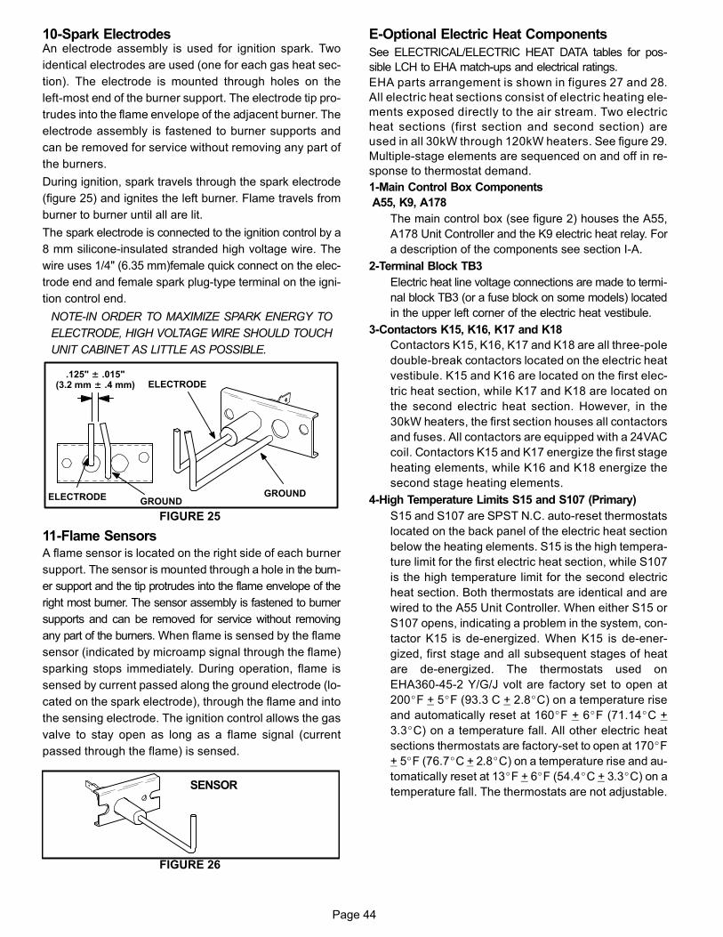
Page 44
10-Spark ElectrodesAn electrode assembly is used for ignition spark. Two
identical electrodes are used (one for each gas heat sec
tion). The electrode is mounted through holes on the
left‐most end of the burner support. The electrode tip pro
trudes into the flame envelope of the adjacent burner. The
electrode assembly is fastened to burner supports and
can be removed for service without removing any part of
the burners.
During ignition, spark travels through the spark electrode
(figure 25) and ignites the left burner. Flame travels from
burner to burner until all are lit.
The spark electrode is connected to the ignition control by a
8 mm silicone‐insulated stranded high voltage wire. The
wire uses 1/4" (6.35 mm)female quick connect on the elec
trode end and female spark plug-type terminal on the igni
tion control end.
NOTE-IN ORDER TO MAXIMIZE SPARK ENERGY TO
ELECTRODE, HIGH VOLTAGE WIRE SHOULD TOUCH
UNIT CABINET AS LITTLE AS POSSIBLE.
GROUND
ELECTRODE
GROUNDELECTRODE
.125" ± .015"(3.2 mm ± .4 mm)
FIGURE 25
11-Flame SensorsA flame sensor is located on the right side of each burner
support. The sensor is mounted through a hole in the burn
er support and the tip protrudes into the flame envelope of the
right most burner. The sensor assembly is fastened to burner
supports and can be removed for service without removing
any part of the burners. When flame is sensed by the flame
sensor (indicated by microamp signal through the flame)
sparking stops immediately. During operation, flame is
sensed by current passed along the ground electrode (lo
cated on the spark electrode), through the flame and into
the sensing electrode. The ignition control allows the gas
valve to stay open as long as a flame signal (current
passed through the flame) is sensed.
FIGURE 26
SENSOR
E-Optional Electric Heat Components
See ELECTRICAL/ELECTRIC HEAT DATA tables for pos
sible LCH to EHA match-ups and electrical ratings.
EHA parts arrangement is shown in figures 27 and 28.
All electric heat sections consist of electric heating ele
ments exposed directly to the air stream. Two electric
heat sections (first section and second section) are
used in all 30kW through 120kW heaters. See figure 29.
Multiple‐stage elements are sequenced on and off in re
sponse to thermostat demand.
1-Main Control Box Components
A55, K9, A178
The main control box (see figure 2) houses the A55,
A178 Unit Controller and the K9 electric heat relay. For
a description of the components see section I‐A.
2-Terminal Block TB3
Electric heat line voltage connections are made to termi
nal block TB3 (or a fuse block on some models) located
in the upper left corner of the electric heat vestibule.
3-Contactors K15, K16, K17 and K18
Contactors K15, K16, K17 and K18 are all three‐pole
double‐break contactors located on the electric heat
vestibule. K15 and K16 are located on the first elec
tric heat section, while K17 and K18 are located on
the second electric heat section. However, in the
30kW heaters, the first section houses all contactors
and fuses. All contactors are equipped with a 24VAC
coil. Contactors K15 and K17 energize the first stage
heating elements, while K16 and K18 energize the
second stage heating elements.
4-High Temperature Limits S15 and S107 (Primary)
S15 and S107 are SPST N.C. auto‐reset thermostats
located on the back panel of the electric heat section
below the heating elements. S15 is the high tempera
ture limit for the first electric heat section, while S107
is the high temperature limit for the second electric
heat section. Both thermostats are identical and are
wired to the A55 Unit Controller. When either S15 or
S107 opens, indicating a problem in the system, con
tactor K15 is de‐energized. When K15 is de‐ener
gized, first stage and all subsequent stages of heat
are de‐energized. The thermostats used on
EHA360-45-2 Y/G/J volt are factory set to open at
200�F + 5�F (93.3 C + 2.8�C) on a temperature rise
and automatically reset at 160�F + 6�F (71.14�C +
3.3�C) on a temperature fall. All other electric heat
sections thermostats are factory-set to open at 170�F
+ 5�F (76.7�C + 2.8�C) on a temperature rise and au
tomatically reset at 13�F + 6�F (54.4�C + 3.3�C) on a
temperature fall. The thermostats are not adjustable.

Page 45
5-Heating Elements HE1 through HE14
Heating elements are composed of helix wound bare
nichrome wire exposed directly to the air stream. Three
elements are connected in a three‐phase arrange
ment. The elements in 208/230V units are connected
in a “Delta" arrangement. Elements in 460 and 575V
units are connected in “Wye" arrangement. See EHA
wiring diagram in WIRING DIAGRAM AND OPERA
TION SEQUENCE section in back of this manual.
Each stage is energized independently by the corre
sponding contactors located on the electric heat vesti
bule panel. Once energized, heat transfer is instanta
neous. High temperature protection is provided by
primary and redundant high temperature limits and
overcurrent protection is provided by fuses.
6-Fuse F3
Fuse F3 are housed in a fuse block which holds three
fuses. Each F3 fuse is connected in series with each
leg of electric heat. Figure 28 and table 7 show the fus
es used with each electric heat section. For simplicity,
the service manual labels the fuses F3 - 1 through F3 -
8.
FIGURE 27
EHA 30, 45, 60, 90 and 120 KW ELECTRIC HEAT SECTION PARTS ARRANGEMENT
PRIMARY ELECTRICHEAT LIMIT
S15(1ST SECTION)S107(2nd SECTION)
HEATING ELEMENTSHE1 - HE14
CONTROL WIREHARNESS
ELECTRIC HEATVESTIBULE

Page 46
FIGURE 28
ELECTRIC HEAT VESTIBULE PARTS ARRANGEMENT
TERMINAL STRIP(TB3)
FIRST STAGE ELECTRICHEAT CONTACTOR K15
SECOND STAGE ELECTRICHEAT CONTACTOR K16
FIRST HEAT SECTION (LEFT SIDE)
SECOND HEAT SECTION (RIGHT SIDE)
FUSE F3F3 ‐ 1 FUSE F3
F3 ‐ 2FUSE F3
F3 ‐ 3
FUSE F3F3 ‐ 4
TERMINAL STRIP(TB3)
FIRST STAGE ELECTRICHEAT CONTACTOR K17
SECOND STAGE ELECTRICHEAT CONTACTOR K18
FUSE F3F3 ‐ 5 FUSE F3
F3 ‐ 6FUSE F3
F3 ‐ 7
FUSE F3F3 ‐ 8
ACCESS DOOR
ACCESS DOOR
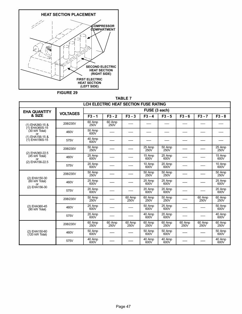
Page 47
FIGURE 29
HEAT SECTION PLACEMENT
FIRST ELECTRICHEAT SECTION
(LEFT SIDE)
SECOND ELECTRICHEAT SECTION(RIGHT SIDE)
COMPRESSORCOMPARTMENT
TABLE 7
LCH ELECTRIC HEAT SECTION FUSE RATING
EHA QUANTITY& SIZE VOLTAGES
FUSE (3 each)
F3 - 1 F3 - 2 F3 - 3 F3 - 4 F3 - 5 F3 - 6 F3 - 7 F3 - 8
(1) EHA360-15 &(1) EHA360S-15
(30 kW Total)or
(1) EHA156-15 &(1) EHA156S-15
208/230V60 Amp250V
60 Amp250V ----- ----- ----- ----- ----- -----
460V50 Amp600V ----- ----- ----- ----- ----- ----- -----
575V40 Amp600V ----- ----- ----- ----- ----- ----- -----
(2) EHA360-22.5(45 kW Total)
or(2) EHA156-22.5
208/230V50 Amp250V ----- -----
25 Amp250V
50 Amp250V ----- -----
25 Amp250V
460V25 Amp600V ----- -----
15 Amp600V
25 Amp600V ----- -----
15 Amp600V
575V20 Amp600V ----- -----
10 Amp600V
20 Amp600V ----- -----
10 Amp600V
(2) EHA150-30(60 kW Total)
or(2) EHA156-30
208/230V50 Amp250V ----- -----
50 Amp250V
50 Amp250V ----- -----
50 Amp250V
460V25 Amp600V ----- -----
25 Amp600V
25 Amp600V ----- -----
25 Amp600V
575V20 Amp600V ----- -----
20 Amp600V
20 Amp600V ----- -----
20 Amp600V
(2) EHA360-45(90 kW Total)
208/230V50 Amp250V -----
60 Amp250V
60 Amp250V
50 Amp250V -----
60 Amp250V
60 Amp250V
460V25 Amp600V ----- -----
50 Amp600V
25 Amp600V ----- -----
50 Amp600V
575V20 Amp600V ----- -----
40 Amp600V
20 Amp600V ----- -----
40 Amp600V
(2) EHA150-60(120 kW Total)
208/230V60 Amp250V
60 Amp250V
60 Amp250V
60 Amp250V
60 Amp250V
60 Amp250V
60 Amp250V
60 Amp250V
460V50 Amp600V ----- -----
50 Amp600V
50 Amp600V ----- -----
50 Amp600V
575V40 Amp600V ----- -----
40 Amp600V
40 Amp600V ----- -----
40 Amp600V
Page 48
II-PLACEMENT AND INSTALLATION
Make sure the unit is installed in accordance with the in
stallation instructions and all applicable codes. See ac
cessories section for conditions requiring use of the op
tional roof mounting frame (LARMF18/36 or
LARMFH30/36).
III-STARTUP - OPERATION - CHARGING
IMPORTANT-The crankcase heater must be energized for
24 hours before attempting to start compressor. Set ther
mostat so there is no demand to prevent compressors from
cycling.
WARNINGRefrigerant can be harmful if it is inhaled. Refrigerantmust be used and recovered responsibly.
Failure to follow this warning may result in personal injury or death.
NOTE - These units must not be used as a “construction heat
er" at any time during any phase of construction. Very low re
turn air temperatures, harmful vapors, and misplacement of
the filters will damage the unit and its efficiency. Additionally, a
unit which will be subject to cold temperatures when not in op
eration must have a vapor barrier installed to seal the duct con
nections. Failure to protect the unit from moisture laden air or
harmful vapors (generated from the construction process and
temporary combustion heating equipment) will cause corro
sive condensation within the unit. Failure to properly protect
the unit in this situation will cause electrical and electronic com
ponent failure and could affect the unit warranty status.
A-Preliminary Checks
1- Make sure that unit is installed in accordance with the
installation instructions and applicable codes.
2- Inspect all electrical wiring, both field‐ and factory‐in
stalled, for loose connections. Tighten as required.
3- Check to ensure that refrigerant lines do not rub against
the cabinet or against other refrigerant lines.
4- Check voltage at disconnect switch. Voltage must be
within range listed on nameplate. If not, consult power
company and have voltage condition corrected before
starting unit.
5- Make sure filters are in place before start‐up.
B-Cooling Start-Up
1- Initiate first and second stage cooling demands ac
cording to instructions provided with thermostat.
2- First-stage thermostat demand will energize com
pressors 1 and 2. Second-stage thermostat demand
will energize compressors 3 and 4. On units with an
economizer, when outdoor air is acceptable, a first-
stage demand will energize the economizer; a second-
stage demand will energize compressors 1 and 2.
3- Units contain four refrigerant circuits or systems. Evap
orator and condenser coil refrigerant circuits 1 and 2
make up stage 1 cooling. Evaporator and condenser
refrigerant circuits 3 and 4 make up stage 2 cooling.
See figures 7 and 8.
4- Each refrigerant circuit is separately charged with
R410A refrigerant. See unit rating plate for correct
amount of charge.
5- Refer to Cooling Operation and Adjustment section for
proper method to check refrigerant charge.
Three Phase Scroll Compressor Voltage Phasing
Three phase scroll compressors must be phased se
quentially to ensure correct compressor and blower* ro
tation and operation. Compressor and blower are wired
in phase at the factory. Power wires are color-coded as
follows: line 1-red, line 2-yellow, line 3-blue.
1- Observe suction and discharge pressures and blower*
rotation on unit start-up.
2- Suction pressure must drop, discharge pressure must
rise, and blower rotation must match rotation marking.
If pressure differential is not observed or blower rotation is
not correct:
3- Disconnect all remote electrical power supplies.
4- Reverse any two field-installed wires connected to the
line side of S48 disconnect or TB13 terminal strip. Do
not reverse wires at blower contactor.
5- Make sure the connections are tight.
Discharge and suction pressures should operate at their
normal start‐up ranges.
*Supply air VFD motors should always rotate in the cor
rect direction regardless of voltage phasing. Verify scroll
compressor rotation separately. Contact technical sup
port if the VFD blower is rotating incorrectly.
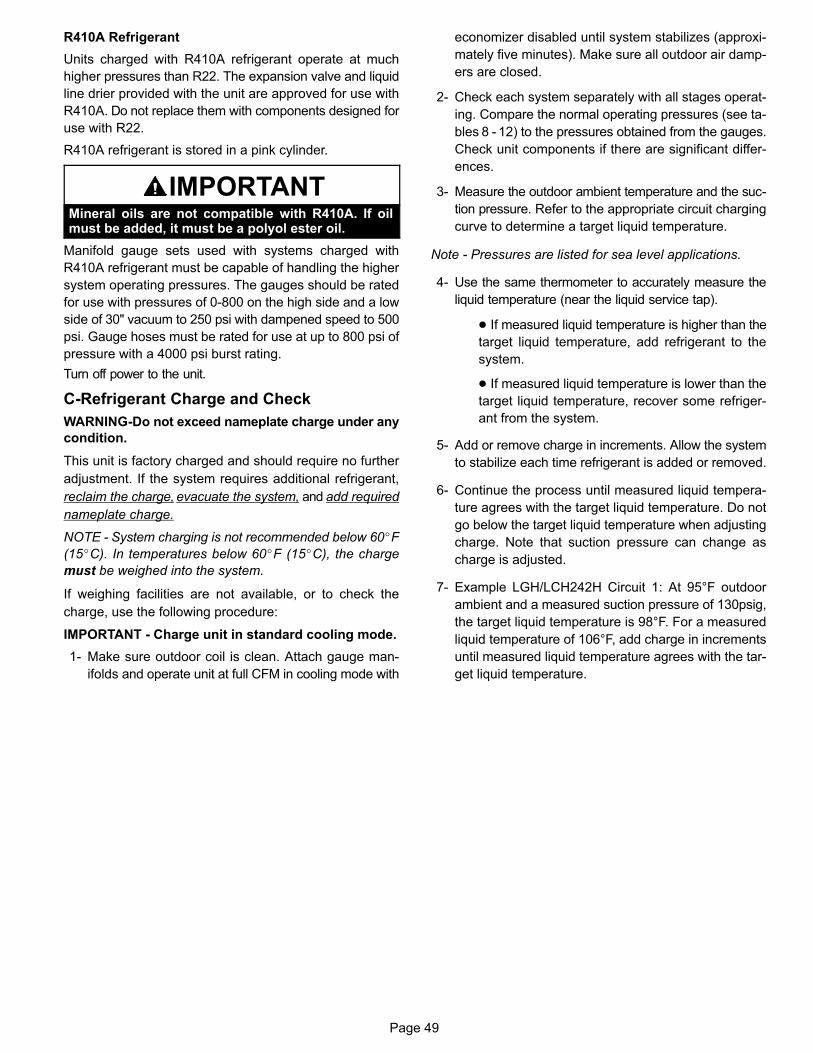
Page 49
R410A Refrigerant
Units charged with R410A refrigerant operate at much
higher pressures than R22. The expansion valve and liquid
line drier provided with the unit are approved for use with
R410A. Do not replace them with components designed for
use with R22.
R410A refrigerant is stored in a pink cylinder.
IMPORTANTMineral oils are not compatible with R410A. If oilmust be added, it must be a polyol ester oil.
Manifold gauge sets used with systems charged with
R410A refrigerant must be capable of handling the higher
system operating pressures. The gauges should be rated
for use with pressures of 0-800 on the high side and a low
side of 30" vacuum to 250 psi with dampened speed to 500
psi. Gauge hoses must be rated for use at up to 800 psi of
pressure with a 4000 psi burst rating.
Turn off power to the unit.
C-Refrigerant Charge and Check
WARNING-Do not exceed nameplate charge under any
condition.
This unit is factory charged and should require no further
adjustment. If the system requires additional refrigerant,
reclaim the charge, evacuate the system, and add required
nameplate charge.
NOTE - System charging is not recommended below 60�F
(15�C). In temperatures below 60�F (15�C), the charge
must be weighed into the system.
If weighing facilities are not available, or to check the
charge, use the following procedure:
IMPORTANT - Charge unit in standard cooling mode.
1- Make sure outdoor coil is clean. Attach gauge man
ifolds and operate unit at full CFM in cooling mode with
economizer disabled until system stabilizes (approxi
mately five minutes). Make sure all outdoor air damp
ers are closed.
2- Check each system separately with all stages operat
ing. Compare the normal operating pressures (see ta
bles 8 - 12) to the pressures obtained from the gauges.
Check unit components if there are significant differ
ences.
3- Measure the outdoor ambient temperature and the suc
tion pressure. Refer to the appropriate circuit charging
curve to determine a target liquid temperature.
Note - Pressures are listed for sea level applications.
4- Use the same thermometer to accurately measure the
liquid temperature (near the liquid service tap).
� If measured liquid temperature is higher than the
target liquid temperature, add refrigerant to the
system.
� If measured liquid temperature is lower than the
target liquid temperature, recover some refriger
ant from the system.
5- Add or remove charge in increments. Allow the system
to stabilize each time refrigerant is added or removed.
6- Continue the process until measured liquid tempera
ture agrees with the target liquid temperature. Do not
go below the target liquid temperature when adjusting
charge. Note that suction pressure can change as
charge is adjusted.
7- Example LGH/LCH242H Circuit 1: At 95°F outdoor
ambient and a measured suction pressure of 130psig,
the target liquid temperature is 98°F. For a measured
liquid temperature of 106°F, add charge in increments
until measured liquid temperature agrees with the tar
get liquid temperature.
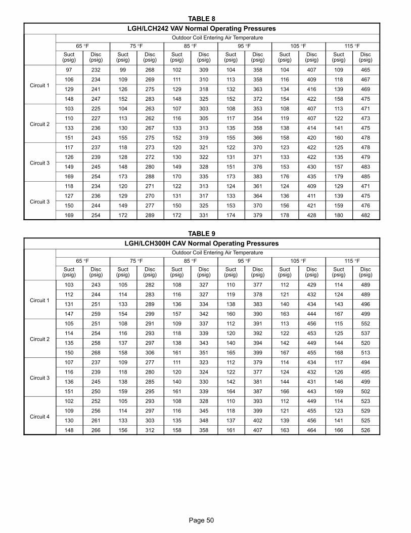
Page 50
TABLE 8
LGH/LCH242 VAV Normal Operating Pressures
Outdoor Coil Entering Air Temperature
65 °F 75 °F 85 °F 95 °F 105 °F 115 °FSuct(psig)
Disc(psig)
Suct(psig)
Disc(psig)
Suct(psig)
Disc(psig)
Suct(psig)
Disc(psig)
Suct(psig)
Disc(psig)
Suct(psig)
Disc(psig)
Circuit 1
97 232 99 268 102 309 104 358 104 407 109 465
106 234 109 269 111 310 113 358 116 409 118 467
129 241 126 275 129 318 132 363 134 416 139 469
148 247 152 283 148 325 152 372 154 422 158 475
Circuit 2
103 225 104 263 107 303 108 353 108 407 113 471
110 227 113 262 116 305 117 354 119 407 122 473
133 236 130 267 133 313 135 358 138 414 141 475
151 243 155 275 152 319 155 366 158 420 160 478
Circuit 3
117 237 118 273 120 321 122 370 123 422 125 478
126 239 128 272 130 322 131 371 133 422 135 479
149 245 148 280 149 328 151 376 153 430 157 483
169 254 173 288 170 335 173 383 176 435 179 485
Circuit 3
118 234 120 271 122 313 124 361 124 409 129 471
127 236 129 270 131 317 133 364 136 411 139 475
150 244 149 277 150 325 153 370 156 421 159 476
169 254 172 289 172 331 174 379 178 428 180 482
TABLE 9
LGH/LCH300H CAV Normal Operating Pressures
Outdoor Coil Entering Air Temperature
65 °F 75 °F 85 °F 95 °F 105 °F 115 °FSuct(psig)
Disc(psig)
Suct(psig)
Disc(psig)
Suct(psig)
Disc(psig)
Suct(psig)
Disc(psig)
Suct(psig)
Disc(psig)
Suct(psig)
Disc(psig)
Circuit 1
103 243 105 282 108 327 110 377 112 429 114 489
112 244 114 283 116 327 119 378 121 432 124 489
131 251 133 289 136 334 138 383 140 434 143 496
147 259 154 299 157 342 160 390 163 444 167 499
Circuit 2
105 251 108 291 109 337 112 391 113 456 115 552
114 254 116 293 118 339 120 392 122 453 125 537
135 258 137 297 138 343 140 394 142 449 144 520
150 268 158 306 161 351 165 399 167 455 168 513
Circuit 3
107 237 109 277 111 323 112 379 114 434 117 494
116 239 118 280 120 324 122 377 124 432 126 495
136 245 138 285 140 330 142 381 144 431 146 499
151 250 159 295 161 339 164 387 166 443 169 502
Circuit 4
102 252 105 293 108 328 110 393 112 449 114 523
109 256 114 297 116 345 118 399 121 455 123 529
130 261 133 303 135 348 137 402 139 456 141 525
148 266 156 312 158 358 161 407 163 464 166 526
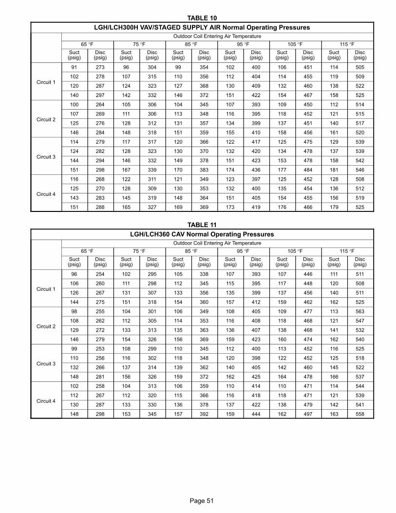
Page 51
TABLE 10
LGH/LCH300H VAV/STAGED SUPPLY AIR Normal Operating Pressures
Outdoor Coil Entering Air Temperature
65 °F 75 °F 85 °F 95 °F 105 °F 115 °FSuct(psig)
Disc(psig)
Suct(psig)
Disc(psig)
Suct(psig)
Disc(psig)
Suct(psig)
Disc(psig)
Suct(psig)
Disc(psig)
Suct(psig)
Disc(psig)
Circuit 1
91 273 96 304 99 354 102 400 106 451 114 505
102 278 107 315 110 356 112 404 114 455 119 509
120 287 124 323 127 368 130 409 132 460 138 522
140 297 142 332 146 372 151 422 154 467 158 525
Circuit 2
100 264 105 306 104 345 107 393 109 450 112 514
107 269 111 306 113 348 116 395 118 452 121 515
125 276 128 312 131 357 134 399 137 451 140 517
146 284 148 318 151 359 155 410 158 456 161 520
Circuit 3
114 279 117 317 120 366 122 417 125 475 129 539
124 282 128 323 130 370 132 420 134 478 137 539
144 294 146 332 149 378 151 423 153 478 158 542
151 298 167 339 170 383 174 436 177 484 181 546
Circuit 4
116 268 122 311 121 349 123 397 125 452 128 508
125 270 128 309 130 353 132 400 135 454 136 512
143 283 145 319 148 364 151 405 154 455 156 519
151 288 165 327 169 369 173 419 176 466 179 525
TABLE 11
LGH/LCH360 CAV Normal Operating Pressures
Outdoor Coil Entering Air Temperature
65 °F 75 °F 85 °F 95 °F 105 °F 115 °FSuct(psig)
Disc(psig)
Suct(psig)
Disc(psig)
Suct(psig)
Disc(psig)
Suct(psig)
Disc(psig)
Suct(psig)
Disc(psig)
Suct(psig)
Disc(psig)
Circuit 1
96 254 102 295 105 338 107 393 107 446 111 511
106 260 111 298 112 345 115 395 117 448 120 508
126 267 131 307 133 356 135 399 137 456 140 511
144 275 151 318 154 360 157 412 159 462 162 525
Circuit 2
98 255 104 301 106 349 108 405 109 477 113 563
108 262 112 305 114 353 116 408 118 468 121 547
129 272 133 313 135 363 136 407 138 468 141 532
146 279 154 326 156 369 159 423 160 474 162 540
Circuit 3
99 253 108 299 110 345 112 400 113 452 116 525
110 256 116 302 118 348 120 398 122 452 125 518
132 266 137 314 139 362 140 405 142 460 145 522
148 281 156 326 159 372 162 425 164 478 166 537
Circuit 4
102 258 104 313 106 359 110 414 110 471 114 544
112 267 112 320 115 366 116 418 118 471 121 539
130 287 133 330 136 378 137 422 138 479 142 541
148 298 153 345 157 392 159 444 162 497 163 558
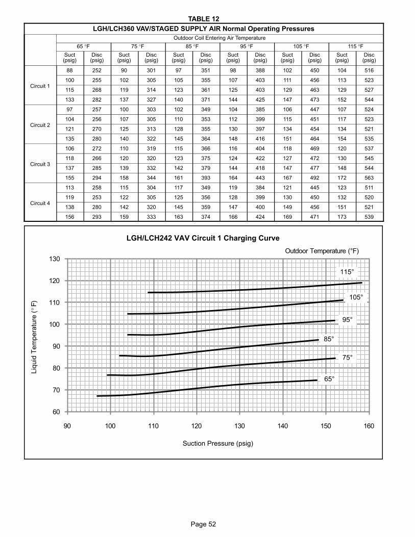
Page 52
TABLE 12
LGH/LCH360 VAV/STAGED SUPPLY AIR Normal Operating Pressures
Outdoor Coil Entering Air Temperature
65 °F 75 °F 85 °F 95 °F 105 °F 115 °FSuct(psig)
Disc(psig)
Suct(psig)
Disc(psig)
Suct(psig)
Disc(psig)
Suct(psig)
Disc(psig)
Suct(psig)
Disc(psig)
Suct(psig)
Disc(psig)
Circuit 1
88 252 90 301 97 351 98 388 102 450 104 516
100 255 102 305 105 355 107 403 111 456 113 523
115 268 119 314 123 361 125 403 129 463 129 527
133 282 137 327 140 371 144 425 147 473 152 544
Circuit 2
97 257 100 303 102 349 104 385 106 447 107 524
104 256 107 305 110 353 112 399 115 451 117 523
121 270 125 313 128 355 130 397 134 454 134 521
135 280 140 322 145 364 148 416 151 464 154 535
Circuit 3
106 272 110 319 115 366 116 404 118 469 120 537
118 266 120 320 123 375 124 422 127 472 130 545
137 285 139 332 142 379 144 418 147 477 148 544
155 294 158 344 161 393 164 443 167 492 172 563
Circuit 4
113 258 115 304 117 349 119 384 121 445 123 511
119 253 122 305 125 356 128 399 130 450 132 520
138 280 142 320 145 359 147 400 149 456 151 521
156 293 159 333 163 374 166 424 169 471 173 539
60
70
80
90
100
110
120
130
90 100 110 120 130 140 150 160
Suction Pressure (psig)
Outdoor Temperature (°F)
115°
105°
95°
85°
75°
65°
LGH/LCH242 VAV Circuit 1 Charging Curve
Liq
uid
Tem
pera
ture
(°F
)
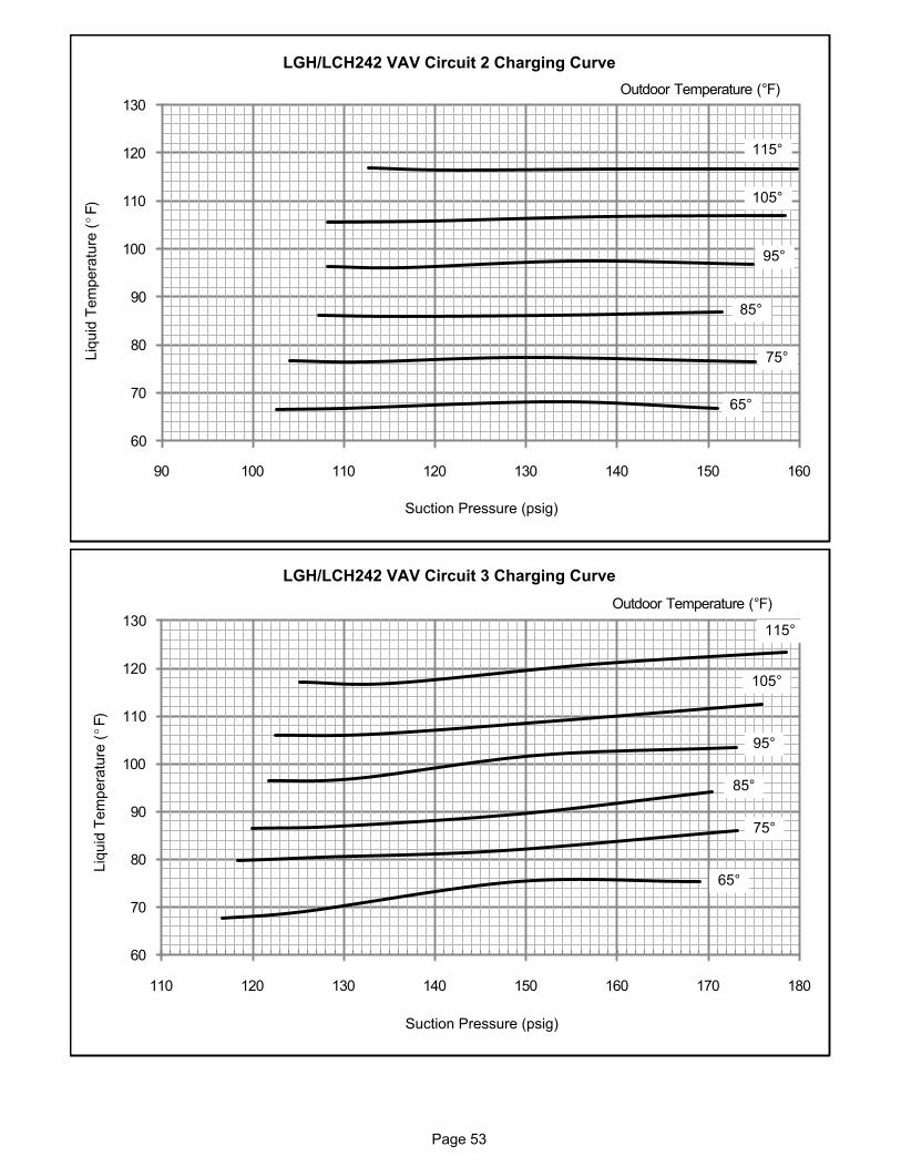
Page 53
60
70
80
90
100
110
120
130
90 100 110 120 130 140 150 160
Suction Pressure (psig)
Outdoor Temperature (°F)
115°
105°
95°
85°
75°
65°
LGH/LCH242 VAV Circuit 2 Charging Curve
Liq
uid
Tem
pera
ture
(°F
)
60
70
80
90
100
110
120
130
110 120 130 140 150 160 170 180
Suction Pressure (psig)
Outdoor Temperature (°F)
115°
105°
95°
85°
75°
65°
LGH/LCH242 VAV Circuit 3 Charging Curve
Liq
uid
Tem
pe
ratu
re (
°F)
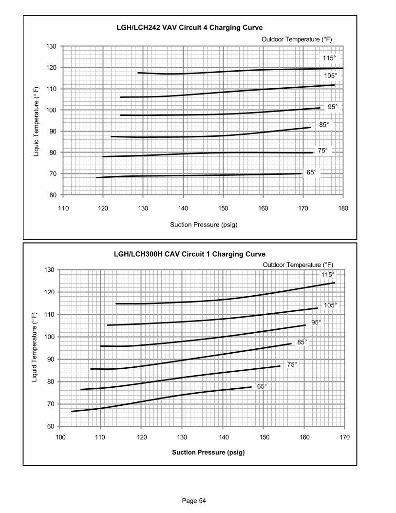
Page 54
60
70
80
90
100
110
120
130
110 120 130 140 150 160 170 180
Suction Pressure (psig)
Outdoor Temperature (°F)
115°
105°
95°
85°
75°
65°
LGH/LCH242 VAV Circuit 4 Charging CurveLiq
uid
Tem
pera
ture
(°F
)
110 120 130 140 150 160 170100
60
70
80
90
100
110
120
130
Suction Pressure (psig)
115°
105°
95°
85°
75°
65°
Outdoor Temperature (°F)
Liq
uid
Tem
pera
ture
(°F
)
LGH/LCH300H CAV Circuit 1 Charging Curve

Page 55
60
70
80
90
100
110
120
130
100 110 120 130 140 150 160 170
Suction Pressure (psig)
115°
105°
95°
85°
75°
65°
Outdoor Temperature (°F)Liq
uid
Tem
pera
ture
(°F
)
LGH/LCH300H CAV Circuit 2 Charging Curve
60
70
80
90
100
110
120
130
100 110 120 130 140 150 160 170
115°
105°
95°
85°
75°
65°
Suction Pressure (psig)
Outdoor Temperature (°F)
Liq
uid
Tem
pera
ture
(°F
)
LGH/LCH300H CAV Circuit 3 Charging Curve
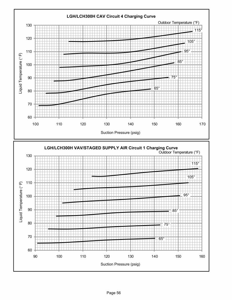
Page 56
60
70
80
90
100
110
120
130
100 110 120 130 140 150 160 170
Suction Pressure (psig)
Liq
uid
Tem
pera
ture
(°F
)
115°
105°
95°
85°
75°
65°
Outdoor Temperature (°F)
LGH/LCH300H CAV Circuit 4 Charging Curve
60
70
80
90
100
110
120
130
90 100 110 120 130 140 150 160
Suction Pressure (psig)
Outdoor Temperature (°F)
Liq
uid
Tem
pera
ture
(°F
)
115°
105°
95°
85°
75°
65°
LGH/LCH300H VAV/STAGED SUPPLY AIR Circuit 1 Charging Curve
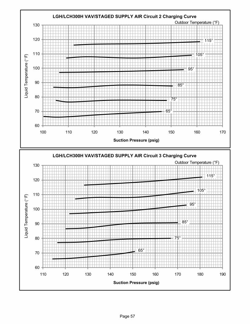
Page 57
60
70
80
90
100
110
120
130
100 110 120 130 140 150 160 170
Suction Pressure (psig)
Outdoor Temperature (°F)Liq
uid
Tem
pera
ture
(°F
)
115°
105°
95°
85°
75°
65°
LGH/LCH300H VAV/STAGED SUPPLY AIR Circuit 2 Charging Curve
60
70
80
90
100
110
120
130
110 120 130 140 150 160 170 180 190
Suction Pressure (psig)
Outdoor Temperature (°F)
Liq
uid
Tem
pera
ture
(°F
)
115°
105°
95°
85°
75°
65°
LGH/LCH300H VAV/STAGED SUPPLY AIR Circuit 3 Charging Curve
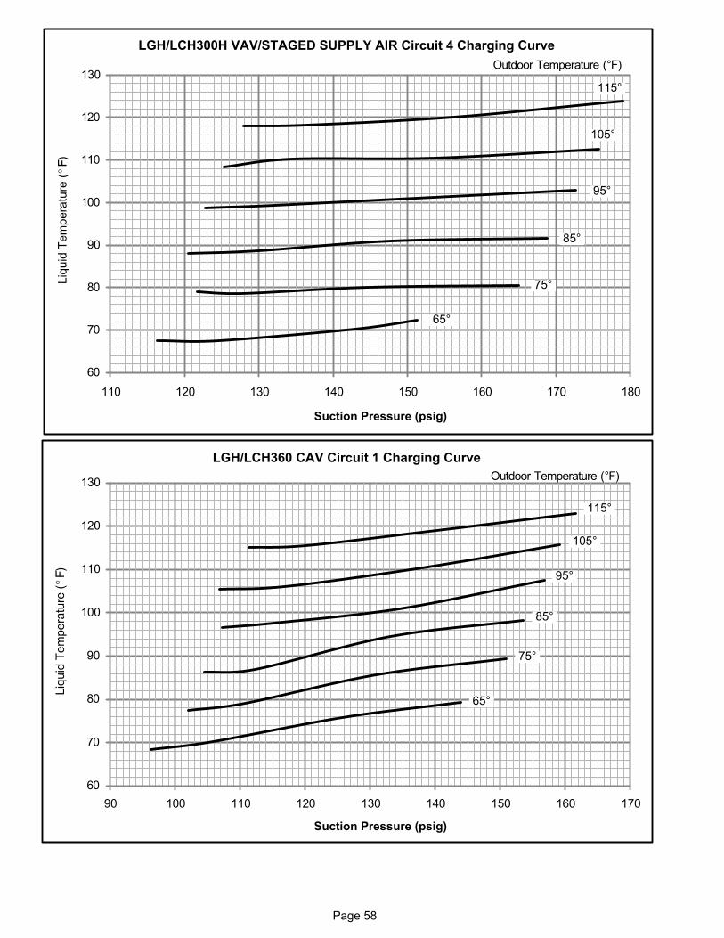
Page 58
60
70
80
90
100
110
120
130
110 120 130 140 150 160 170 180
Suction Pressure (psig)
Outdoor Temperature (°F)Liq
uid
Tem
pera
ture
(°F
)
115°
105°
95°
85°
75°
65°
LGH/LCH300H VAV/STAGED SUPPLY AIR Circuit 4 Charging Curve
60
70
80
90
100
110
120
130
90 100 110 120 130 140 150 160 170
Suction Pressure (psig)
Outdoor Temperature (°F)
Liq
uid
Tem
pera
ture
(°F
)
115°
105°
95°
85°
75°
65°
LGH/LCH360 CAV Circuit 1 Charging Curve
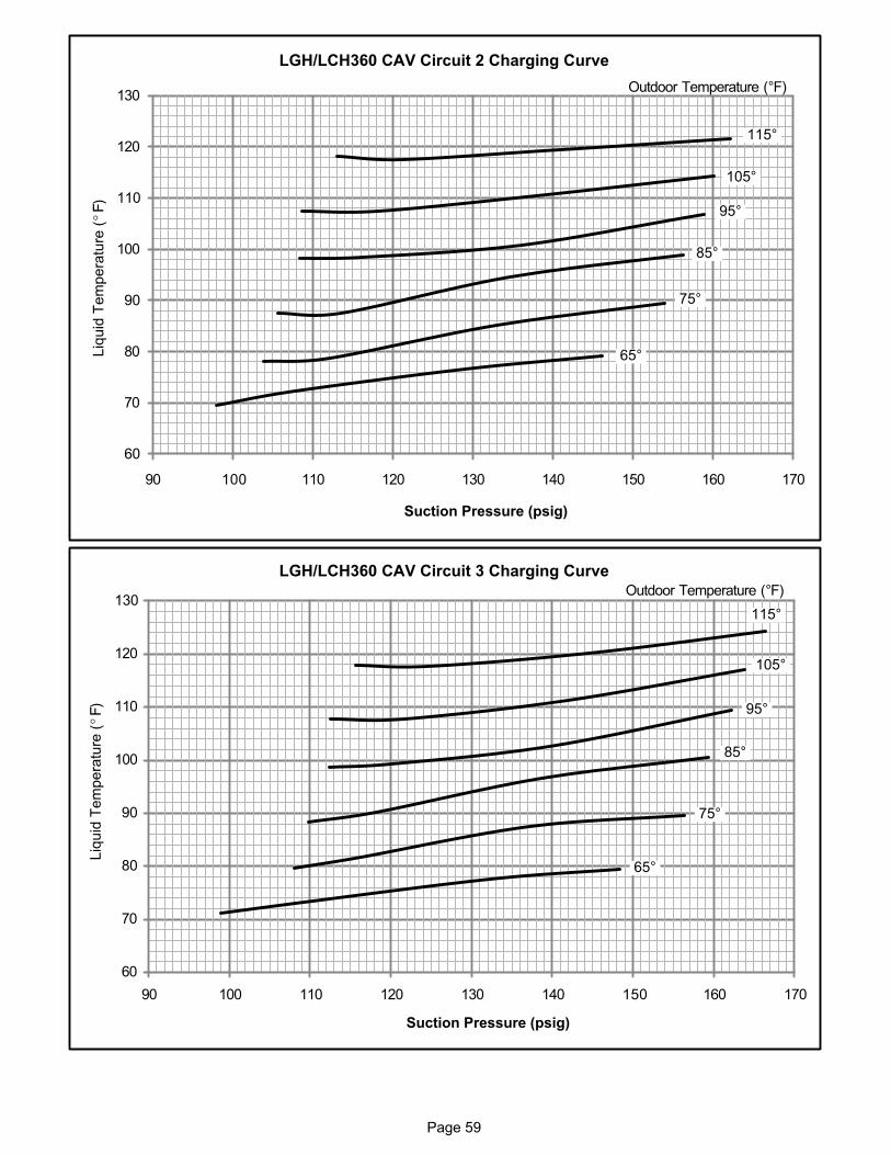
Page 59
60
70
80
90
100
110
120
130
90 100 110 120 130 140 150 160 170
Suction Pressure (psig)
Outdoor Temperature (°F)Liq
uid
Tem
pera
ture
(°F
)
115°
105°
95°
85°
75°
65°
LGH/LCH360 CAV Circuit 2 Charging Curve
60
70
80
90
100
110
120
130
90 100 110 120 130 140 150 160 170
Suction Pressure (psig)
Outdoor Temperature (°F)
Liq
uid
Tem
pera
ture
(°F
)
115°
105°
95°
85°
75°
65°
LGH/LCH360 CAV Circuit 3 Charging Curve
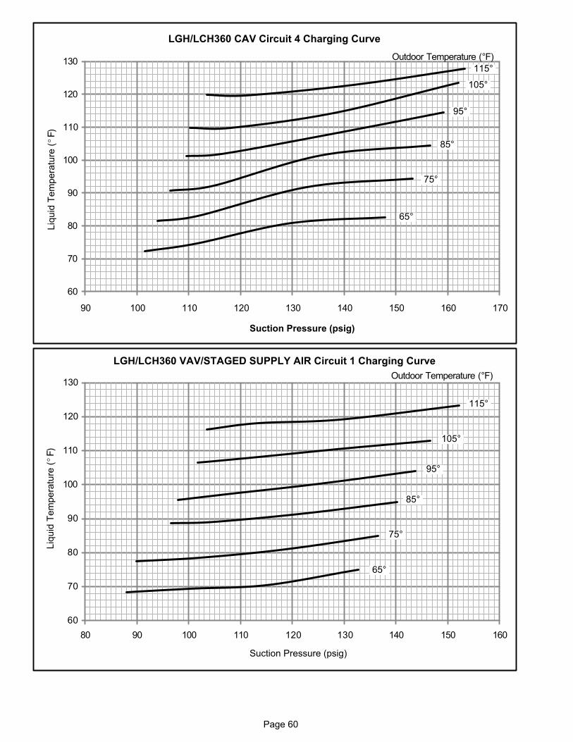
Page 60
60
70
80
90
100
110
120
130
90 100 110 120 130 140 150 160 170
Suction Pressure (psig)
Outdoor Temperature (°F)Liq
uid
Tem
pera
ture
(°F
)
115°
105°
95°
85°
75°
65°
LGH/LCH360 CAV Circuit 4 Charging Curve
60
70
80
90
100
110
120
130
80 90 100 110 120 130 140 150 160
Suction Pressure (psig)
Outdoor Temperature (°F)
Liq
uid
Tem
pera
ture
(°F
)
115°
105°
95°
85°
75°
65°
LGH/LCH360 VAV/STAGED SUPPLY AIR Circuit 1 Charging Curve
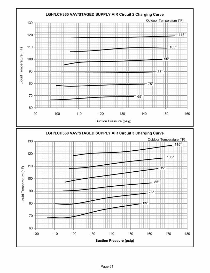
Page 61
60
70
80
90
100
110
120
130
90 100 110 120 130 140 150 160
Suction Pressure (psig)
Outdoor Temperature (°F)Liq
uid
Tem
pera
ture
(°F
)
115°
105°
95°
85°
75°
65°
LGH/LCH360 VAV/STAGED SUPPLY AIR Circuit 2 Charging Curve
60
70
80
90
100
110
120
130
100 110 120 130 140 150 160 170 180
Suction Pressure (psig)
Outdoor Temperature (°F)
Liq
uid
Tem
pera
ture
(°F
)
115°
105°
95°
85°
75°
65°
LGH/LCH360 VAV/STAGED SUPPLY AIR Circuit 3 Charging Curve
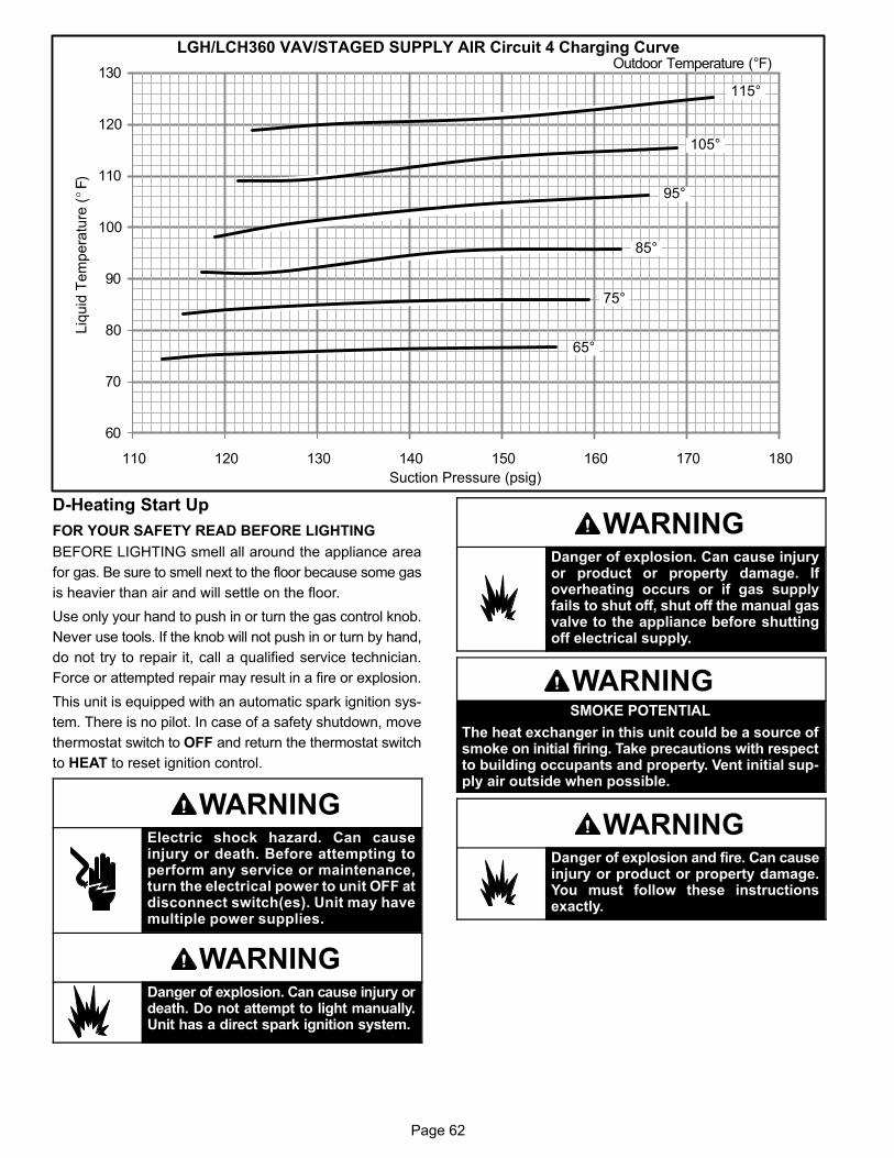
Page 62
60
70
80
90
100
110
120
130
110 120 130 140 150 160 170 180
Suction Pressure (psig)
Outdoor Temperature (°F)
Liq
uid
Tem
pera
ture
(°F
)115°
105°
95°
85°
75°
65°
LGH/LCH360 VAV/STAGED SUPPLY AIR Circuit 4 Charging Curve
D-Heating Start Up
FOR YOUR SAFETY READ BEFORE LIGHTING
BEFORE LIGHTING smell all around the appliance area
for gas. Be sure to smell next to the floor because some gas
is heavier than air and will settle on the floor.
Use only your hand to push in or turn the gas control knob.
Never use tools. If the knob will not push in or turn by hand,
do not try to repair it, call a qualified service technician.
Force or attempted repair may result in a fire or explosion.
This unit is equipped with an automatic spark ignition sys
tem. There is no pilot. In case of a safety shutdown, move
thermostat switch to OFF and return the thermostat switch
to HEAT to reset ignition control.
WARNINGElectric shock hazard. Can causeinjury or death. Before attempting toperform any service or maintenance,turn the electrical power to unit OFF atdisconnect switch(es). Unit may havemultiple power supplies.
WARNINGDanger of explosion. Can cause injury ordeath. Do not attempt to light manually.Unit has a direct spark ignition system.
WARNINGDanger of explosion. Can cause injuryor product or property damage. Ifoverheating occurs or if gas supplyfails to shut off, shut off the manual gasvalve to the appliance before shuttingoff electrical supply.
WARNINGSMOKE POTENTIAL
The heat exchanger in this unit could be a source ofsmoke on initial firing. Take precautions with respectto building occupants and property. Vent initial supply air outside when possible.
WARNINGDanger of explosion and fire. Can causeinjury or product or property damage.You must follow these instructionsexactly.
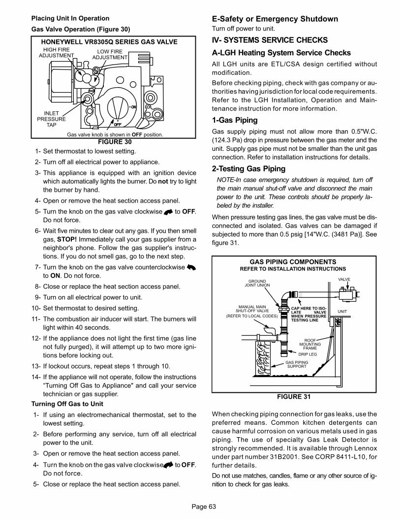
Page 63
Placing Unit In Operation
Gas Valve Operation (Figure 30)
HONEYWELL VR8305Q SERIES GAS VALVE
Gas valve knob is shown in OFF position.
FIGURE 30
LOW FIREADJUSTMENT
HIGH FIREADJUSTMENT
INLETPRESSURE
TAP
1- Set thermostat to lowest setting.
2- Turn off all electrical power to appliance.
3- This appliance is equipped with an ignition device
which automatically lights the burner. Do not try to light
the burner by hand.
4- Open or remove the heat section access panel.
5- Turn the knob on the gas valve clockwise to OFF.
Do not force.
6- Wait five minutes to clear out any gas. If you then smell
gas, STOP! Immediately call your gas supplier from a
neighbor's phone. Follow the gas supplier's instruc
tions. If you do not smell gas, go to the next step.
7- Turn the knob on the gas valve counterclockwise
to ON. Do not force.
8- Close or replace the heat section access panel.
9- Turn on all electrical power to unit.
10- Set thermostat to desired setting.
11- The combustion air inducer will start. The burners will
light within 40 seconds.
12- If the appliance does not light the first time (gas line
not fully purged), it will attempt up to two more igni
tions before locking out.
13- If lockout occurs, repeat steps 1 through 10.
14- If the appliance will not operate, follow the instructions
“Turning Off Gas to Appliance" and call your service
technician or gas supplier.
Turning Off Gas to Unit
1- If using an electromechanical thermostat, set to the
lowest setting.
2- Before performing any service, turn off all electrical
power to the unit.
3- Open or remove the heat section access panel.
4- Turn the knob on the gas valve clockwise to OFF.
Do not force.
5- Close or replace the heat section access panel.
E-Safety or Emergency Shutdown
Turn off power to unit.
IV- SYSTEMS SERVICE CHECKS
A-LGH Heating System Service Checks
All LGH units are ETL/CSA design certified without
modification.
Before checking piping, check with gas company or au
thorities having jurisdiction for local code requirements.
Refer to the LGH Installation, Operation and Main
tenance instruction for more information.
1-Gas Piping
Gas supply piping must not allow more than 0.5"W.C.
(124.3 Pa) drop in pressure between the gas meter and the
unit. Supply gas pipe must not be smaller than the unit gas
connection. Refer to installation instructions for details.
2-Testing Gas Piping
NOTE-In case emergency shutdown is required, turn off
the main manual shut‐off valve and disconnect the main
power to the unit. These controls should be properly la
beled by the installer.
When pressure testing gas lines, the gas valve must be dis
connected and isolated. Gas valves can be damaged if
subjected to more than 0.5 psig [14"W.C. (3481 Pa)]. See
figure 31.
UNIT
GROUNDJOINT UNION
MANUAL MAINSHUT-OFF VALVE
(REFER TO LOCAL CODES)
GAS PIPINGSUPPORT
DRIP LEG
ROOFMOUNTING
FRAME
GAS PIPING COMPONENTSREFER TO INSTALLATION INSTRUCTIONS
FIGURE 31
VALVE
CAP HERE TO ISOLATE VALVEWHEN PRESSURETESTING LINE
When checking piping connection for gas leaks, use the
preferred means. Common kitchen detergents can
cause harmful corrosion on various metals used in gas
piping. The use of specialty Gas Leak Detector is
strongly recommended. It is available through Lennox
under part number 31B2001. See CORP 8411-L10, for
further details.
Do not use matches, candles, flame or any other source of ig
nition to check for gas leaks.
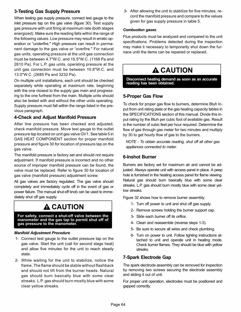
Page 64
3-Testing Gas Supply Pressure
When testing gas supply pressure, connect test gauge to the
inlet pressure tap on the gas valve (figure 30). Test supply
gas pressure with unit firing at maximum rate (both stages
energized). Make sure the reading falls within the range of
the following values. Low pressure may result in erratic op
eration or “underfire." High pressure can result in perma
nent damage to the gas valve or “overfire." For natural
gas units, operating pressure at the unit gas connection
must be between 4.7"W.C. and 10.5"W.C. (1168 Pa and
2610 Pa). For L.P. gas units, operating pressure at the
unit gas connection must be between 10.8"W.C. and
13.0"W.C. (2685 Pa and 3232 Pa).
On multiple unit installations, each unit should be checked
separately while operating at maximum rate, beginning
with the one closest to the supply gas main and progress
ing to the one furthest from the main. Multiple units should
also be tested with and without the other units operating.
Supply pressure must fall within the range listed in the pre
vious paragraph.
4-Check and Adjust Manifold Pressure
After line pressure has been checked and adjusted,
check manifold pressure. Move test gauge to the outlet
pressure tap located on unit gas valve GV1. See table 5 in
GAS HEAT COMPONENT section for proper manifold
pressure and figure 30 for location of pressure tap on the
gas valve.
The manifold pressure is factory set and should not require
adjustment. If manifold pressure is incorrect and no other
source of improper manifold pressure can be found, the
valve must be replaced. Refer to figure 30 for location of
gas valve (manifold pressure) adjustment screw.
All gas valves are factory regulated. The gas valve should
completely and immediately cycle off in the event of gas or
power failure. The manual shut‐off knob can be used to imme
diately shut off gas supply.
CAUTIONFor safety, connect a shut‐off valve between themanometer and the gas tap to permit shut off ofgas pressure to the manometer.
Manifold Adjustment Procedure
1- Connect test gauge to the outlet pressure tap on the
gas valve. Start the unit (call for second stage heat)
and allow five minutes for the unit to reach steady
state.
2- While waiting for the unit to stabilize, notice the
flame. The flame should be stable without flashback
and should not lift from the burner heads. Natural
gas should burn basically blue with some clear
streaks. L.P. gas should burn mostly blue with some
clear yellow streaks.
3- After allowing the unit to stabilize for five minutes, re
cord the manifold pressure and compare to the values
given for gas supply pressure in table 5.
Combustion gases
Flue products must be analyzed and compared to the unit
specifications. Problems detected during the inspection
may make it necessary to temporarily shut down the fur
nace until the items can be repaired or replaced.
CAUTIONDisconnect heating demand as soon as an accuratereading has been obtained.
5-Proper Gas Flow
To check for proper gas flow to burners, determine Btuh in
put from unit rating plate or the gas heating capacity tables in
the SPECIFICATIONS section of this manual. Divide this in
put rating by the Btuh per cubic foot of available gas. Result
is the number of cubic feet per hour required. Determine the
flow of gas through gas meter for two minutes and multiply
by 30 to get hourly flow of gas to the burners.
NOTE - To obtain accurate reading, shut off all other gas
appliances connected to meter.
6-Inshot Burner
Burners are factory set for maximum air and cannot be ad
justed. Always operate unit with access panel in place. A peep
hole is furnished in the heating access panel for flame viewing.
Natural gas should burn basically blue with some clear
streaks. L.P. gas should burn mostly blue with some clear yel
low streaks.
Figure 32 shows how to remove burner assembly.
1- Turn off power to unit and shut off gas supply.
2- Remove screws holding the burner support cap.
3- Slide each burner off its orifice.
4- Clean and reassemble (reverse steps 1-3).
5- Be sure to secure all wires and check plumbing.
6- Turn on power to unit. Follow lighting instructions at
tached to unit and operate unit in heating mode.
Check burner flames. They should be blue with yellow
streaks.
7-Spark Electrode Gap
The spark electrode assembly can be removed for inspection
by removing two screws securing the electrode assembly
and sliding it out of unit.
For proper unit operation, electrodes must be positioned and
gapped correctly.
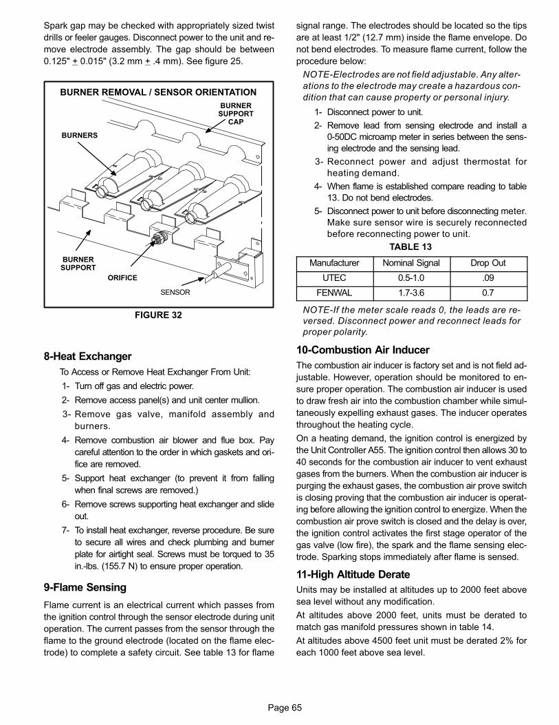
Page 65
Spark gap may be checked with appropriately sized twist
drills or feeler gauges. Disconnect power to the unit and re
move electrode assembly. The gap should be between
0.125" + 0.015" (3.2 mm + .4 mm). See figure 25.
FIGURE 32
BURNER REMOVAL / SENSOR ORIENTATION
BURNERS
ORIFICE
BURNERSUPPORT
BURNERSUPPORT
CAP
SENSOR
8-Heat Exchanger
To Access or Remove Heat Exchanger From Unit:
1- Turn off gas and electric power.
2- Remove access panel(s) and unit center mullion.
3- Remove gas valve, manifold assembly and
burners.
4- Remove combustion air blower and flue box. Pay
careful attention to the order in which gaskets and ori
fice are removed.
5- Support heat exchanger (to prevent it from falling
when final screws are removed.)
6- Remove screws supporting heat exchanger and slide
out.
7- To install heat exchanger, reverse procedure. Be sure
to secure all wires and check plumbing and burner
plate for airtight seal. Screws must be torqued to 35
in.‐lbs. (155.7 N) to ensure proper operation.
9-Flame Sensing
Flame current is an electrical current which passes from
the ignition control through the sensor electrode during unit
operation. The current passes from the sensor through the
flame to the ground electrode (located on the flame elec
trode) to complete a safety circuit. See table 13 for flame
signal range. The electrodes should be located so the tips
are at least 1/2" (12.7 mm) inside the flame envelope. Do
not bend electrodes. To measure flame current, follow the
procedure below:
NOTE-Electrodes are not field adjustable. Any alter
ations to the electrode may create a hazardous con
dition that can cause property or personal injury.
1- Disconnect power to unit.
2- Remove lead from sensing electrode and install a
0-50DC microamp meter in series between the sens
ing electrode and the sensing lead.
3- Reconnect power and adjust thermostat for
heating demand.
4- When flame is established compare reading to table
13. Do not bend electrodes.
5- Disconnect power to unit before disconnecting meter.
Make sure sensor wire is securely reconnected
before reconnecting power to unit.
TABLE 13
Manufacturer Nominal Signal Drop Out
UTEC 0.5-1.0 .09
FENWAL 1.7-3.6 0.7
NOTE-If the meter scale reads 0, the leads are re
versed. Disconnect power and reconnect leads for
proper polarity.
10-Combustion Air Inducer
The combustion air inducer is factory set and is not field ad
justable. However, operation should be monitored to en
sure proper operation. The combustion air inducer is used
to draw fresh air into the combustion chamber while simul
taneously expelling exhaust gases. The inducer operates
throughout the heating cycle.
On a heating demand, the ignition control is energized by
the Unit Controller A55. The ignition control then allows 30 to
40 seconds for the combustion air inducer to vent exhaust
gases from the burners. When the combustion air inducer is
purging the exhaust gases, the combustion air prove switch
is closing proving that the combustion air inducer is operat
ing before allowing the ignition control to energize. When the
combustion air prove switch is closed and the delay is over,
the ignition control activates the first stage operator of the
gas valve (low fire), the spark and the flame sensing elec
trode. Sparking stops immediately after flame is sensed.
11-High Altitude Derate
Units may be installed at altitudes up to 2000 feet above
sea level without any modification.
At altitudes above 2000 feet, units must be derated to
match gas manifold pressures shown in table 14.
At altitudes above 4500 feet unit must be derated 2% for
each 1000 feet above sea level.
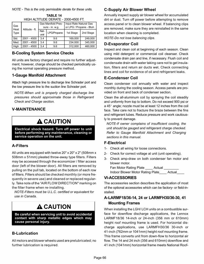
Page 66
NOTE - This is the only permissible derate for these units.
TABLE 14HIGH ALTITUDE DERATE - 2000-4500 FT.
Gas
Heat
Type
Altitude - ft.
Gas Manifold Pres
sure - in. w.g.
Input Rate Natural Gas
or LPG / Propane - Btuh
Nat
uralLPG/Propane 1st Stage 2nd Stage
Std. 2001 - 4500 3.4 9.6 169,000 249,000
Med. 2001 - 4500 3.4 9.6 234,000 345,000
High 2001 - 4500 3.4 9.6 312,000 460,000
B-Cooling System Service Checks
All units are factory charged and require no further adjust
ment; however, charge should be checked periodically us
ing the normal operating pressure method.
1-Gauge Manifold Attachment
Attach high pressure line to discharge line Schrader port and
the low pressure line to the suction line Schrader port.
NOTE-When unit is properly charged discharge line
pressures should approximate those in Refrigerant
Check and Charge section.
V-MAINTENANCE
CAUTIONElectrical shock hazard. Turn off power to unitbefore performing any maintenance, cleaning orservice operation on the unit.
A-Filters
All units are equipped with twelve 20" x 20" x 2" (508mm x
508mm x 51mm) pleated throw-away type filters. Filters
may be accessed through the economizer / filter access
door (left of the blower door). All filters are removed by
pulling on the pull tab, located on the bottom of each row
of filters. Filters should be checked monthly (or more fre
quently in severe use) and cleaned or replaced regular
ly. Take note of the “AIR FLOW DIRECTION" marking on
the filter frame when re-installing.
NOTE-Filters must be U.L.C. certified or equivalent for
use in Canada.
CAUTIONBe careful when servicing unit to avoid accidentalcontact with sharp metallic edges which maycause personal injury.
B-Lubrication
All motors and blower wheels used are prelubricated; no
further lubrication is required.
C-Supply Air Blower Wheel
Annually inspect supply air blower wheel for accumulated
dirt or dust. Turn off power before attempting to remove
access panel or to clean blower wheel. If balancing clips
are removed, make sure they are reinstalled in the same
location when cleaning is completed.
NOTE-Do not lose balancing clips.
D-Evaporator Coil
Inspect and clean coil at beginning of each season. Clean
using mild detergent or commercial coil cleanser. Check
condensate drain pan and line, if necessary. Flush coil and
condensate drain with water taking care not to get insula
tion, filters and return air ducts wet. Check connecting
lines and coil for evidence of oil and refrigerant leaks.
E-Condenser Coil
Clean condenser coil annually with water and inspect
monthly during the cooling season. Access panels are pro
vided on front and back of condenser section.
Clean the all-aluminum coil by spraying the coil steadily
and uniformly from top to bottom. Do not exceed 900 psi or
a 45� angle; nozzle must be at least 12 inches from the coil
face. Take care not to fracture the braze between the fins
and refrigerant tubes. Reduce pressure and work cautious
ly to prevent damage.
NOTE-If owner complains of insufficient cooling, the
unit should be gauged and refrigerant charge checked.
Refer to Gauge Manifold Attachment and Charging
sections in this manual.
F-Electrical
1- Check all wiring for loose connections.
2- Check for correct voltage at unit (unit operating).
3- Check amp-draw on both condenser fan motor and
blower motor.
Fan Motor Rating Plate ____ Actual ________
Indoor Blower Motor Rating Plate____ Actual____
VI-ACCESSORIES
The accessories section describes the application of most
of the optional accessories which can be factory- or field-in
stalled.
A-LARMF18/36‐14, 24 or LARMFH30/36-30, 41
Mounting Frames
When installing the LGH/ LCH units on a combustible sur
face for downflow discharge applications, the Lennox
LARMF18/36 14‐inch or 24‐inch (356 mm or 610mm)
height roof mounting frame is used. For horizontal dis
charge applications, use LARMFH30/36 30‐inch or
41‐inch (762mm or 1041mm) height roof mounting frame.
This frame converts unit from down‐flow to horizontal air
flow. The 14 and 24 inch (356 and 610mm) downflow and
41 inch (1041mm) horizontal frame meets National Roof
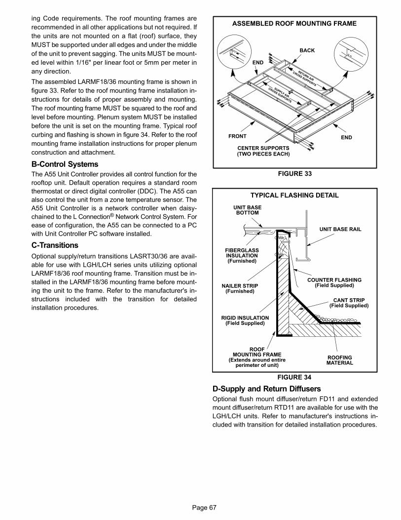
Page 67
ing Code requirements. The roof mounting frames are
recommended in all other applications but not required. If
the units are not mounted on a flat (roof) surface, they
MUST be supported under all edges and under the middle
of the unit to prevent sagging. The units MUST be mount
ed level within 1/16" per linear foot or 5mm per meter in
any direction.
The assembled LARMF18/36 mounting frame is shown in
figure 33. Refer to the roof mounting frame installation in
structions for details of proper assembly and mounting.
The roof mounting frame MUST be squared to the roof and
level before mounting. Plenum system MUST be installed
before the unit is set on the mounting frame. Typical roof
curbing and flashing is shown in figure 34. Refer to the roof
mounting frame installation instructions for proper plenum
construction and attachment.
B-Control Systems
The A55 Unit Controller provides all control function for the
rooftop unit. Default operation requires a standard room
thermostat or direct digital controller (DDC). The A55 can
also control the unit from a zone temperature sensor. The
A55 Unit Controller is a network controller when daisy-
chained to the L Connection® Network Control System. For
ease of configuration, the A55 can be connected to a PC
with Unit Controller PC software installed.
C-Transitions
Optional supply/return transitions LASRT30/36 are avail
able for use with LGH/LCH series units utilizing optional
LARMF18/36 roof mounting frame. Transition must be in
stalled in the LARMF18/36 mounting frame before mount
ing the unit to the frame. Refer to the manufacturer's in
structions included with the transition for detailed
installation procedures.
FIGURE 33
ASSEMBLED ROOF MOUNTING FRAME
FRONT
END
END
BACK
CENTER SUPPORTS(TWO PIECES EACH)
FIGURE 34
ROOFMOUNTING FRAME
(Extends around entireperimeter of unit)
FIBERGLASSINSULATION(Furnished)
COUNTER FLASHING(Field Supplied)
UNIT BASEBOTTOM
RIGID INSULATION(Field Supplied)
ROOFINGMATERIAL
CANT STRIP(Field Supplied)
NAILER STRIP(Furnished)
UNIT BASE RAIL
TYPICAL FLASHING DETAIL
D-Supply and Return Diffusers
Optional flush mount diffuser/return FD11 and extended
mount diffuser/return RTD11 are available for use with the
LGH/LCH units. Refer to manufacturer's instructions in
cluded with transition for detailed installation procedures.
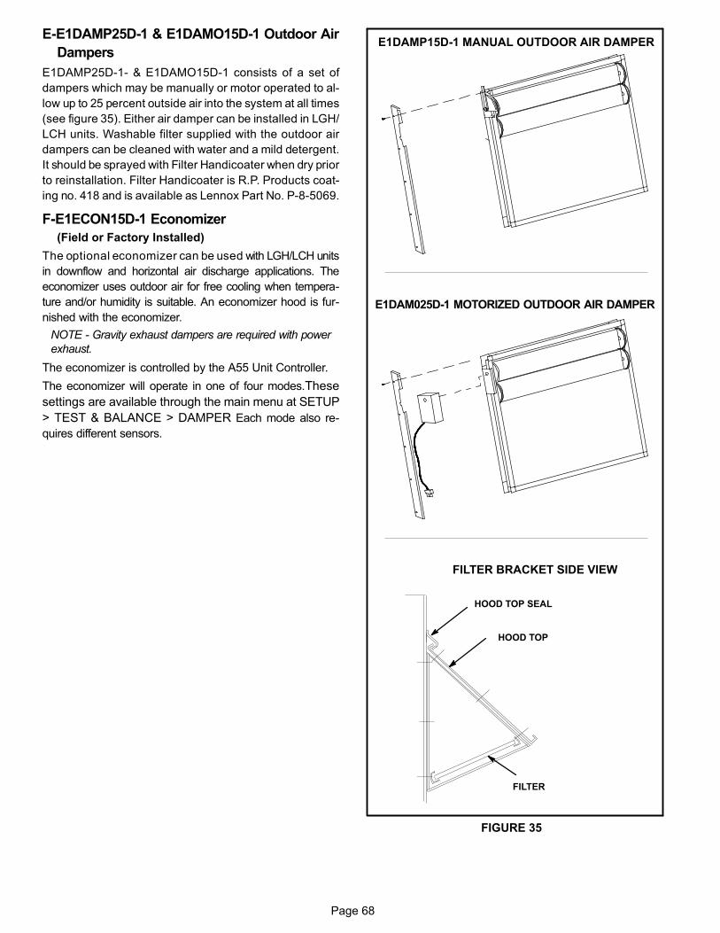
Page 68
E-E1DAMP25D-1 & E1DAMO15D-1 Outdoor Air
Dampers
E1DAMP25D-1- & E1DAMO15D-1 consists of a set of
dampers which may be manually or motor operated to al
low up to 25 percent outside air into the system at all times
(see figure 35). Either air damper can be installed in LGH/
LCH units. Washable filter supplied with the outdoor air
dampers can be cleaned with water and a mild detergent.
It should be sprayed with Filter Handicoater when dry prior
to reinstallation. Filter Handicoater is R.P. Products coat
ing no. 418 and is available as Lennox Part No. P-8-5069.
F-E1ECON15D-1 Economizer
(Field or Factory Installed)
The optional economizer can be used with LGH/LCH units
in downflow and horizontal air discharge applications. The
economizer uses outdoor air for free cooling when tempera
ture and/or humidity is suitable. An economizer hood is fur
nished with the economizer.
NOTE - Gravity exhaust dampers are required with power
exhaust.
The economizer is controlled by the A55 Unit Controller.
The economizer will operate in one of four modes.These
settings are available through the main menu at SETUP
> TEST & BALANCE > DAMPER Each mode also re
quires different sensors.
E1DAM025D-1 MOTORIZED OUTDOOR AIR DAMPER
E1DAMP15D-1 MANUAL OUTDOOR AIR DAMPER
FIGURE 35
FILTER BRACKET SIDE VIEW
HOOD TOP
FILTER
HOOD TOP SEAL
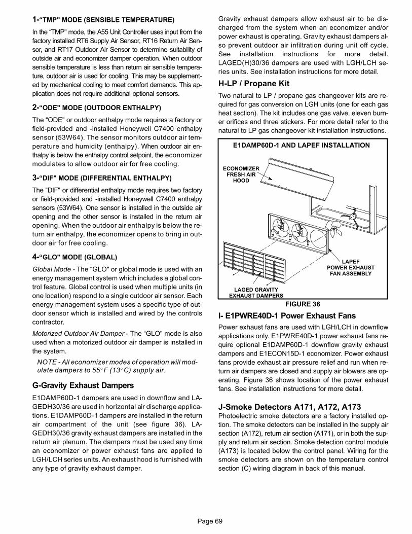
Page 69
1-“TMP" MODE (SENSIBLE TEMPERATURE)
In the “TMP" mode, the A55 Unit Controller uses input from the
factory installed RT6 Supply Air Sensor, RT16 Return Air Sen
sor, and RT17 Outdoor Air Sensor to determine suitability of
outside air and economizer damper operation. When outdoor
sensible temperature is less than return air sensible tempera
ture, outdoor air is used for cooling. This may be supplement
ed by mechanical cooling to meet comfort demands. This ap
plication does not require additional optional sensors.
2-“ODE" MODE (OUTDOOR ENTHALPY)
The “ODE" or outdoor enthalpy mode requires a factory or
field-provided and -installed Honeywell C7400 enthalpy
sensor (53W64). The sensor monitors outdoor air tem
perature and humidity (enthalpy). When outdoor air en
thalpy is below the enthalpy control setpoint, the economizer
modulates to allow outdoor air for free cooling.
3-“DIF" MODE (DIFFERENTIAL ENTHALPY)
The “DIF" or differential enthalpy mode requires two factory
or field-provided and -installed Honeywell C7400 enthalpy
sensors (53W64). One sensor is installed in the outside air
opening and the other sensor is installed in the return air
opening. When the outdoor air enthalpy is below the re
turn air enthalpy, the economizer opens to bring in out
door air for free cooling.
4-“GLO" MODE (GLOBAL)
Global Mode - The “GLO" or global mode is used with an
energy management system which includes a global con
trol feature. Global control is used when multiple units (in
one location) respond to a single outdoor air sensor. Each
energy management system uses a specific type of out
door sensor which is installed and wired by the controls
contractor.
Motorized Outdoor Air Damper - The “GLO" mode is also
used when a motorized outdoor air damper is installed in
the system.
NOTE - All economizer modes of operation will mod
ulate dampers to 55�F (13�C) supply air.
G-Gravity Exhaust Dampers
E1DAMP60D-1 dampers are used in downflow and LA
GEDH30/36 are used in horizontal air discharge applica
tions. E1DAMP60D-1 dampers are installed in the return
air compartment of the unit (see figure 36). LA
GEDH30/36 gravity exhaust dampers are installed in the
return air plenum. The dampers must be used any time
an economizer or power exhaust fans are applied to
LGH/LCH series units. An exhaust hood is furnished with
any type of gravity exhaust damper.
Gravity exhaust dampers allow exhaust air to be dis
charged from the system when an economizer and/or
power exhaust is operating. Gravity exhaust dampers al
so prevent outdoor air infiltration during unit off cycle.
See installation instructions for more detail.
LAGED(H)30/36 dampers are used with LGH/LCH se
ries units. See installation instructions for more detail.
H-LP / Propane Kit
Two natural to LP / propane gas changeover kits are re
quired for gas conversion on LGH units (one for each gas
heat section). The kit includes one gas valve, eleven burn
er orifices and three stickers. For more detail refer to the
natural to LP gas changeover kit installation instructions.
FIGURE 36
LAPEFPOWER EXHAUSTFAN ASSEMBLY
LAGED GRAVITYEXHAUST DAMPERS
ECONOMIZERFRESH AIR
HOOD
E1DAMP60D-1 AND LAPEF INSTALLATION
I- E1PWRE40D-1 Power Exhaust Fans
Power exhaust fans are used with LGH/LCH in downflow
applications only. E1PWRE40D-1 power exhaust fans re
quire optional E1DAMP60D-1 downflow gravity exhaust
dampers and E1ECON15D-1 economizer. Power exhaust
fans provide exhaust air pressure relief and run when re
turn air dampers are closed and supply air blowers are op
erating. Figure 36 shows location of the power exhaust
fans. See installation instructions for more detail.
J-Smoke Detectors A171, A172, A173 Photoelectric smoke detectors are a factory installed op
tion. The smoke detectors can be installed in the supply air
section (A172), return air section (A171), or in both the sup
ply and return air section. Smoke detection control module
(A173) is located below the control panel. Wiring for the
smoke detectors are shown on the temperature control
section (C) wiring diagram in back of this manual.
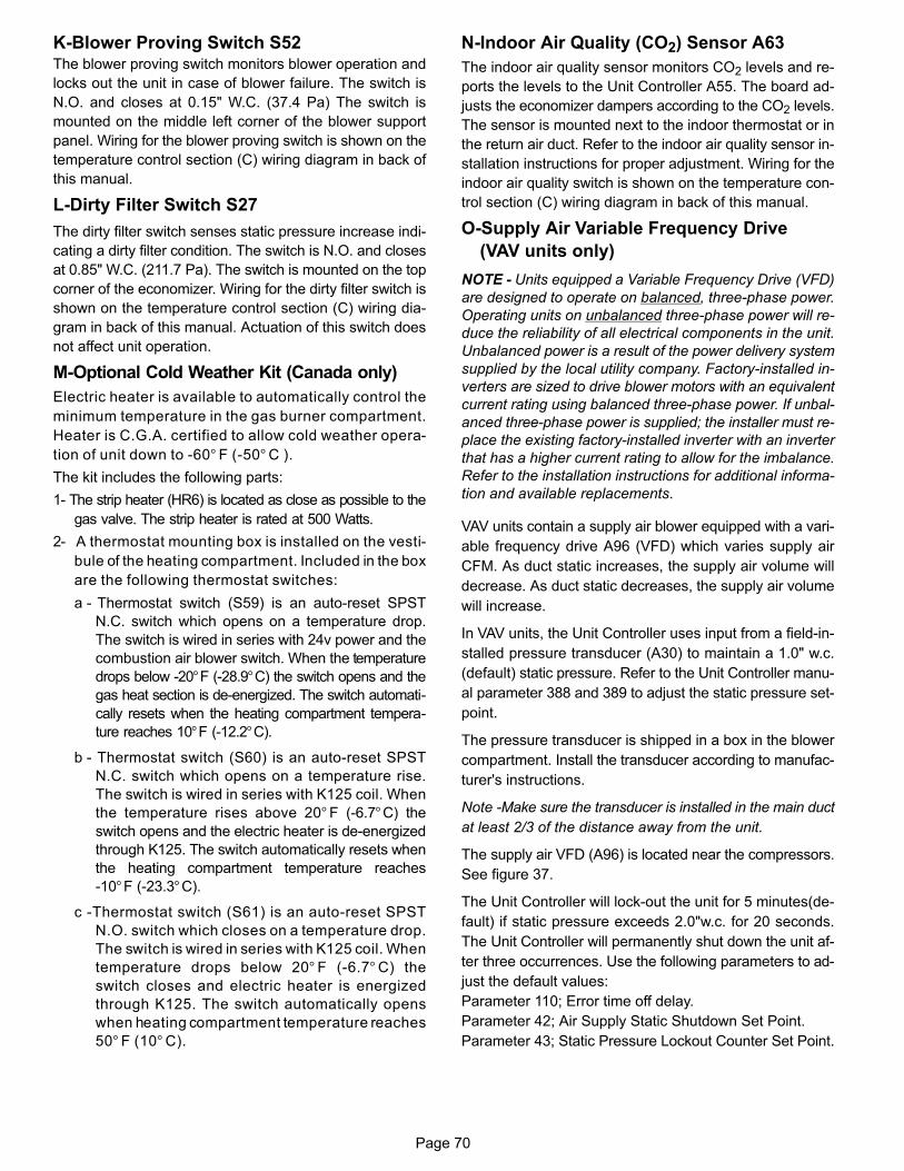
Page 70
K-Blower Proving Switch S52 The blower proving switch monitors blower operation and
locks out the unit in case of blower failure. The switch is
N.O. and closes at 0.15" W.C. (37.4 Pa) The switch is
mounted on the middle left corner of the blower support
panel. Wiring for the blower proving switch is shown on the
temperature control section (C) wiring diagram in back of
this manual.
L-Dirty Filter Switch S27
The dirty filter switch senses static pressure increase indi
cating a dirty filter condition. The switch is N.O. and closes
at 0.85" W.C. (211.7 Pa). The switch is mounted on the top
corner of the economizer. Wiring for the dirty filter switch is
shown on the temperature control section (C) wiring dia
gram in back of this manual. Actuation of this switch does
not affect unit operation.
M-Optional Cold Weather Kit (Canada only)
Electric heater is available to automatically control the
minimum temperature in the gas burner compartment.
Heater is C.G.A. certified to allow cold weather opera
tion of unit down to ‐60° F (‐50° C ).
The kit includes the following parts:
1- The strip heater (HR6) is located as close as possible to the
gas valve. The strip heater is rated at 500 Watts.
2- A thermostat mounting box is installed on the vesti
bule of the heating compartment. Included in the box
are the following thermostat switches:
a - Thermostat switch (S59) is an auto‐reset SPST
N.C. switch which opens on a temperature drop.
The switch is wired in series with 24v power and the
combustion air blower switch. When the temperature
drops below ‐20°F (-28.9°C) the switch opens and the
gas heat section is de‐energized. The switch automati
cally resets when the heating compartment tempera
ture reaches 10°F (‐12.2°C).
b - Thermostat switch (S60) is an auto‐reset SPST
N.C. switch which opens on a temperature rise.
The switch is wired in series with K125 coil. When
the temperature rises above 20° F (‐6.7°C) the
switch opens and the electric heater is de‐energized
through K125. The switch automatically resets when
the heating compartment temperature reaches
‐10°F (-23.3°C).
c -Thermostat switch (S61) is an auto‐reset SPST
N.O. switch which closes on a temperature drop.
The switch is wired in series with K125 coil. When
temperature drops below 20° F (‐6.7° C) the
switch closes and electric heater is energized
through K125. The switch automatically opens
when heating compartment temperature reaches
50° F (10° C).
N-Indoor Air Quality (CO2) Sensor A63
The indoor air quality sensor monitors CO2 levels and re
ports the levels to the Unit Controller A55. The board ad
justs the economizer dampers according to the CO2 levels.
The sensor is mounted next to the indoor thermostat or in
the return air duct. Refer to the indoor air quality sensor in
stallation instructions for proper adjustment. Wiring for the
indoor air quality switch is shown on the temperature con
trol section (C) wiring diagram in back of this manual.
O-Supply Air Variable Frequency Drive
(VAV units only)
NOTE - Units equipped a Variable Frequency Drive (VFD)
are designed to operate on balanced, three-phase power.
Operating units on unbalanced three-phase power will re
duce the reliability of all electrical components in the unit.
Unbalanced power is a result of the power delivery system
supplied by the local utility company. Factory-installed in
verters are sized to drive blower motors with an equivalent
current rating using balanced three-phase power. If unbal
anced three-phase power is supplied; the installer must re
place the existing factory-installed inverter with an inverter
that has a higher current rating to allow for the imbalance.
Refer to the installation instructions for additional informa
tion and available replacements.
VAV units contain a supply air blower equipped with a vari
able frequency drive A96 (VFD) which varies supply air
CFM. As duct static increases, the supply air volume will
decrease. As duct static decreases, the supply air volume
will increase.
In VAV units, the Unit Controller uses input from a field-in
stalled pressure transducer (A30) to maintain a 1.0" w.c.
(default) static pressure. Refer to the Unit Controller manu
al parameter 388 and 389 to adjust the static pressure set
point.
The pressure transducer is shipped in a box in the blower
compartment. Install the transducer according to manufac
turer's instructions.
Note -Make sure the transducer is installed in the main duct
at least 2/3 of the distance away from the unit.
The supply air VFD (A96) is located near the compressors.
See figure 37.
The Unit Controller will lock-out the unit for 5 minutes(de
fault) if static pressure exceeds 2.0"w.c. for 20 seconds.
The Unit Controller will permanently shut down the unit af
ter three occurrences. Use the following parameters to ad
just the default values:
Parameter 110; Error time off delay.
Parameter 42; Air Supply Static Shutdown Set Point.
Parameter 43; Static Pressure Lockout Counter Set Point.

Page 71
VAV By-Pass Operation (Optional)
IMPORTANT - All dampers must be open to prevent
damage to duct work and dampers.
1- Turn off all power to unit.
2- Locate K3, K203, J248 and J249 connectors near the
VFD. See figure 41.
3- Disconnect J248 from P248 and connect connect
P248 jumper plug to J248. P248 jumper plug is at
tached to the J248 wire harness near the J248 jack
connector. See figure 40.
4- Disconnect P247 from J247 and connect J249 to
P247. See figure 39.
FIGURE 37
SUPPLY AIR VARIABLE FREQUENCY DRIVE
A96 SUPPLYAIR VFD
K203-A
VAV BY-PASS CONNECTOR
K203-A
K203-A
K3-A
From Relay ConnectFrom Contactor
FIGURE 38
K203-B
K3-B
K203-B
K203-B From A55
From A55
Disconnect
J249
BY-PASS CONNECTOR
P247
J247
P247
Disconnect Connect
FIGURE 39
P248Jumper
Plug
J248
VAV BY-PASS CONNECTOR
P248
J248
Disconnect
Connect
FIGURE 40
5- Locate VFD control relay K203 on the lower control
panel. See figure 41.
6- Disconnect wires marked K203-A and K203-B
7- Connect K3-A (female terminal) to K203-A (male ter
minal) and K3-B (female terminal) to K3-B (male termi
nal)
8- Restore power to unit. Blower will operate in constant
air volume (CAV) mode.
9- Check the indoor blower motor nameplate for full load
amperage (FLA) value. Measure the amp readings
from the indoor blower motor operating in bypass
mode. If measured amps are higher than nameplate
FLA value, decrease the CFM by opening (turning
counterclockwise) the motor pulley. Refer to the Indoor
Blower Motor section. Do not exceed minimum and
maximum number of pulley turns as shown in table 1.
P-Drain Pan Overflow Switch S149 (optional)The overflow switch is used to interrupt cooling operation
when excessive condensate collects in the drain pan. The
N.O. overflow switch is controlled by K220 and DL46 re
lays, located in the unit control panel. When the overflow
switch closes, 24VAC power is interrupted and after a five-
second delay the unit compressors are de-energized.
Once the condensate level drops below the set level, the
switch will open. After a five-minute delay the compressor
will be energized.

Page 72
SUPPLY AIR VFD BY-PASS COMPONENTS
FIGURE 41
VII-WIRING DIAGRAMS AND
OPERATION SEQUENCE
The following pages contain the wiring diagrams for LGH/
LCH242/300/360 series units. An economizer and ther
mostat are also shown. Each wiring diagram is followed by
a sequence of operation.
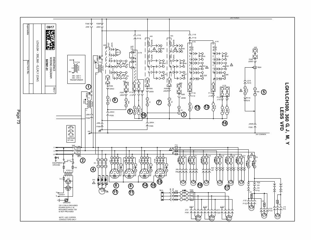
Pag
e 7
3
B2 B20B1
F6F6
F10
B13
F30
F31
K3
A
B
K65
A
B
S42
B3
K20
5
A
B
GND GND
K14
9
A
B
K15
0
A
B
K10
A
B K68
A
B
K2
A
B
K1
A
B
BLK
K15
3
A
B
K15
2
A
B
K14
A
B
K14
6
A
B
A178 A178
A178
A55 A55
K1-2
C
NC
K2-2
C
NC
K14-2
C
NC
K146-2
C
NC
1
2
3
4
5
7
8 8
9
9
10
11 11
13 13
1415
16
16
1718
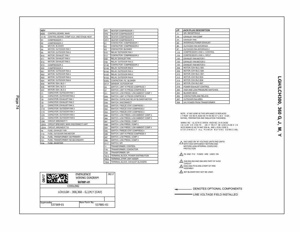
Pag
e 7
4
NOTE - IF ANY WIRE IN THIS APPLIANCE IS REPLACED
I T MUST B E RE PL ACED WI TH WI RE O F L IK E S IZE ,
RATING, TERMINATION AND INSULATION THICKNESS.
WARN I NG - EL ECTR IC SHOCK HAZA RD, CA N CAUSE
I N J U RY O R D EA TH . UN I T MU S T BE G RO U N DE D I N
ACCO RDAN CE WI TH NAT ION AL AND L OCAL CODE S.
D I S C O N N E C T A LL P O W E R B E F O R E S E RVI C I NG.
S42 USED ON ”M” VOLTAGE UNITS AND UNITSWITH HIGH EFFICIENCY MOTORS ANDMOTORS LESS INTERNAL OVERLOADPROTECTION
F6 AND F10 FUSES ARE USED ON
B37 BLOWER MAY NOT BE USED
212 MOTOR, EXH BLO B35
213 MOTOR, EXH BLO B36
214 MOTOR, EXH BLO B37
18 EXHAUST FAN COMP
24 EXHAUST FAN
69 INTERFACE,POWER EXHAUST
86 OUTDOOR FAN INTERFACE
87 OUTDOOR FAN INTERFACE 2
118 COMPRESSOR 3 AND 4, CONTROL
119 COMPRESSOR 3 AND 4, INPUT
132 EXHAUST FAN MOTOR 1
133 EXHAUST FAN MOTOR 2
134 EXHAUST FAN MOTOR 3
208 MOTOR, EXH BLO, B35
209 MOTOR, EXH BLO, B36
210 MOTOR, EXH BLO, B37
218 POWER EXHAUST CONTROL
263 HIGH AND LOW PRESSURE SWITCHES
264 BLOWER DECK
265 CONTACTORS AND RELAYS
267 OUTDOOR FAN AREA
268 24V POWER FROM TRANSFORMER
S49,S50,S53 AND S95 ARE PART OF 5VDCCIRCUIT
J/P JACK/PLUG DESCRIPTION
K205 AND P218 ARE A PART OF RRSASSEMBLY
11 GFI, RECEPTACLEKEY
CONTROL BOARD, MAIN
A178
B1 COMPRESSOR 1
B2 COMPRESSOR 2
B3 MOTOR, BLOWER
B4 MOTOR, OUTDOOR FAN 1
B5 MOTOR, OUTDOOR FAN 2
B10 MOTOR, EXHAUST FAN 1
B11 MOTOR, EXHAUST FAN 2
B12 MOTOR, EXHAUST FAN 3
B13 COMPRESSOR 3
B20 COMPRESSOR 4
B21 MOTOR, OUTDOOR FAN 3
B22 MOTOR, OUTDOOR FAN 4
B23 MOTOR, OUTDOOR FAN 5
B24 MOTOR, OUTDOOR FAN 6
B35 MOTOR, EXH, BLO 1
B36 MOTOR, EXH, BLO 2
B37 MOTOR, EXH, BLO 3
C1 CAPACITOR, OUTDOOR FAN 1
C2 CAPACITOR, OUTDOOR FAN 2
C6 CAPACITOR, EXHAUST FAN 1
C8 CAPACITOR, EXHAUST FAN 2
C9 CAPACITOR, EXHAUST FAN 3
C18 CAPACITOR, OUTDOOR FAN 3
C19 CAPACITOR, OUTDOOR FAN 4
C20 CAPACITOR, OUTDOOR FAN 5
C21 CAPACITOR, OUTDOOR FAN 6
CB8 CIRCUIT, BREAKER T1
CB10 CIRCUIT BREAKER, MAIN DISCONNECT UNIT
CB18 CIRCUIT, BREAKER T18
F6 FUSE, EXHAUST FAN
F10 FUSE, OUTDOOR FAN MOTOR
F30 FUSE, TRANSFORMER T29 PRIMARY
F31 FUSE, TRANSFORMER T29 SECONDARY
F36 FUSE, INVERTER
CONTROL BOARD, COMP 3 & 4, 2ND STAGE HEAT
HR1 HEATER COMPRESSOR 1
HR2 HEATER COMPRESSOR 2
HR5 HEATER COMPRESSOR 3
HR11 HEATER COMPRESSOR 4
K1 CONTACTOR, COMPRESSOR 1
K2 CONTACTOR, COMPRESSOR 2
K3 CONTACTOR, BLOWER
K10 RELAY, OUTDOOR FAN 1
K14 CONTACTOR, COMPRESSOR 3
K65 RELAY, EXHAUST FAN
K68 RELAY, OUTDOOR FAN 2
K146 CONTACTOR, COMPRESSOR 4
K149 RELAY, OUTDOOR FAN 3
K150 RELAY, OUTDOOR FAN 4
K152 RELAY, OUTDOOR FAN 5
K153 RELAY, OUTDOOR FAN 6
K205 CONTACTOR, P.E. BLOWER
RT17 SENSOR, OUTDOOR AIR
S4 SWITCH, LIMIT HI PRESS COMPRESS 1
S7 SWITCH, LIMIT HI PRESS COMPRESS 2
S11 SWITCH, LOW PRESS, LOW AMBIENT COMP 1
S28 SWITCH, LIMIT HI PRESS COMPRESS 3
S42 SWITCH, OVERLOAD RELAY BLOWER MOTOR
S48 SWITCH, DISCONNECT
S49 SWITCH, FREEZE STAT COMPRESS 1
S50 SWITCH, FREEZE STAT COMPRESS 2
S53 SWITCH, FREEZE STAT COMPRESS 3
S84 SWITCH, LOW PRESS, LOW AMBIENT COMP 2
S85 SWITCH, LOW PRESS, LOW AMBIENT COMP 3
S87 SWITCH, LOW PRESS, COMP 1
S88 SWITCH, LOW PRESS, COMP 2
S94 SWITCH, LOW PRESS, LOW AMBIENT COMP 4
S95 SWITCH, FREEZE STAT COMPRESS 4
S96 SWITCH, LIMIT HI PRESS COMPRESS 4
S97 SWITCH, LOW PRESS, COMP 4
S98 SWITCH, LOW PRESS, COMP 3
S117 SWITCH, GFI
T1 TRANSFORMER, CONTROL
T18 TRANSFORMER, CONTACTOR
T29 TRANSFORMER, GFI
TB13 TERMINAL BLOCK, POWER DISTRIBUTION
TB24 TERMINAL STRIP, UNIT ADDER
TB58 TERMINAL BLOCK, EXHAUST BLOWERS
COOLING
537369-01 537881-01
A55
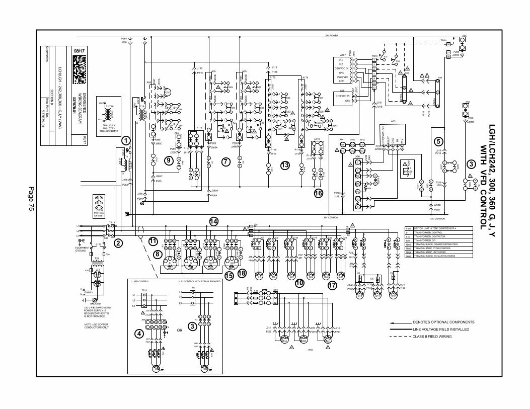
Pag
e 7
5
2
4
5
10
14
11
16
3
13
15
1
8
9
17
18
B2 B20B1
F10
B13
F30
F31
K14
9
A
B
K15
0
K10
K68
A
B
K2
A
B
K1
A
B
K20
3
K20
7
A
B
0-10 VDC IN
K65
A
B
24V COMMON
7
K3
A
B
+
−
+S
A30
+
O
−
A347
6
T1 TRANSFORMER, CONTROL
T18 TRANSFORMER, CONTACTOR
T29 TRANSFORMER, GFI
TB13 TERMINAL BLOCK, POWER DISTRIBUTION
TB24 TERMINAL STRIP, UNIT ADDER
VIA
A137
CC
VIA
A141
CC
VIA
A142
CC
TB13
B3
R S T
W VU
G
G
A96
B3
B3 CONTROL WITH BYPASS ENGAGEDVFD CONTROL1. 2.
9
8
S180 SWITCH, LIMIT HI TEMP COMPRESSOR 4
9
BLK
SD
STF
C
B
2
5
6
9
TB13
K15
3
A
BK15
2
K14
K14
6
F6
F6
K23
1
A
B
8
6
11RRS
10
BYPASS
TB58 TERMINAL BLOCK, EXHAUST BLOWERS
10
GND
K1-2
C
NC
K14-2
C
NC
K2-2
C
NC
K146-2
C
NC
5
TB18 TERMINAL STRIP, CYCLE CONTROL
PWH/VDC
0-10 VDC IN
GND
COM
DI2
DI1
20 VFBD
NG
YA
LE
R
OV/
1M
WP)
BDI (
PC
R55
10
K20
5 37
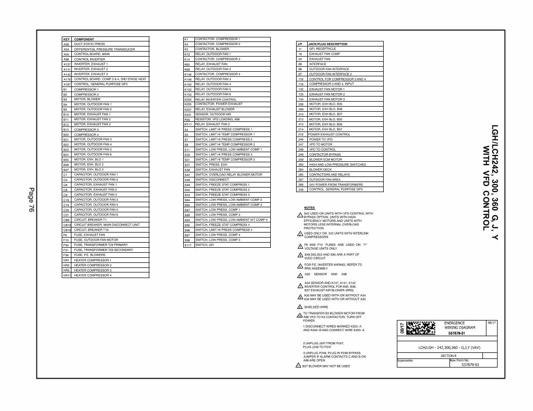
Pag
e 7
6
18 EXHAUST FAN COMP
24 EXHAUST FAN
86 OUTDOOR FAN INTERFACE
87 OUTDOOR FAN INTERFACE 2
118 CONTROL FOR COMPRESSOR 3 AND 4
119 COMPRESSOR 3 AND 4, INPUT
132 EXHAUST FAN MOTOR 1
133 EXHAUST FAN MOTOR 2
134 EXHAUST FAN MOTOR 3
246 POWER TO VFD
247 VFD TO MOTOR
248 VFD TO CONTROL
249 CONTACTOR BYPASS
263 HIGH AND LOW PRESSURE SWITCHES
264 BLOWER DECK
265 CONTACTORS AND RELAYS
267 OUTDOOR FAN AREA
268 24V POWER FROM TRANSFORMERS
J/P JACK/PLUG DESCRIPTION
218 POWER EXHAUST CONTROL
259 BLOWER ECM MOTOR
69 INTERFACE
209 MOTOR, EXH BLO, B36
210 MOTOR, EXH BLO, B37
212
213
214
208 MOTOR, EXH BLO, B35
MOTOR, EXH BLO, B36
MOTOR, EXH BLO, B37
MOTOR, EXH BLO, B35
348 CONTROL, GENERAL PURPOSE GP3
11 GFI, RECEPTACLE
S42 USED ON UNITS WITH VFD CONTROL WITHBYPASS OPTION, UNITS WITH HIGHEFFICIENCY MOTORS AND UNITS WITHMOTORS LESS INTERNAL OVERLOADPROTECTION
USED ONLY ON 242 UNITS WITH INTERLINKCOMPRESSORS
F6 AND F10 FUSES ARE USED ON ”Y”VOLTAGE UNITS ONLY
S49,S50,S53 AND S95 ARE A PART OF5VDC CIRCUIT
FOR P.E. INVERTER WIRING, REFER TORRS ASSEMBLY
A30 SENSOR AND A96
A34 SENSOR AND A137, A141, A142INVERTER CONTROL FOR B35, B36,B37 EXHAUST AIR BLOWER (RRS)
A30 MAY BE USED WITH OR WITHOUT A34A34 MAY BE USED WITH OR WITHOUT A30
SHIELDED WIRE
NOTES
TO TRANSFER B3 BLOWER MOTOR FROMA96 VFD TO K3 CONTACTOR, TURN OFFPOWER
1.DISCONNECT WIRES MARKED K203−AAND K203−B AND CONNECT WIRE K203−A
2.UNPLUG J247 FROM P247,PLUG J249 TO P247
3.UNPLUG P248, PLUG IN P248 BYPASSJUMPER IF ALARM CONTACTS C AND B ONA96 ARE OPEN
10
11 B37 BLOWER MAY NOT BE USED
KEY COMPONENT
A30 DUCT STATIC PRESS
A34 DIFFERENTIAL PRESSURE TRANSDUCER
A55 CONTROL BOARD, MAIN
A96 CONTROL INVERTER
A142 INVERTER, EXHAUST 3
B1 COMPRESSOR 1
B2 COMPRESSOR 2
B3 MOTOR, BLOWER
B4 MOTOR, OUTDOOR FAN 1
B5 MOTOR, OUTDOOR FAN 2
B10 MOTOR, EXHAUST FAN 1
B11 MOTOR, EXHAUST FAN 2
B12 MOTOR, EXHAUST FAN 3
B13 COMPRESSOR 3
B20 COMPRESSOR 4
B21 MOTOR, OUTDOOR FAN 3
B22 MOTOR, OUTDOOR FAN 4
B23 MOTOR, OUTDOOR FAN 5
B24 MOTOR, OUTDOOR FAN 6
C1 CAPACITOR, OUTDOOR FAN 1
C2 CAPACITOR, OUTDOOR FAN 2
C6 CAPACITOR, EXHAUST FAN 1
C8 CAPACITOR, EXHAUST FAN 2
C9 CAPACITOR, EXHAUST FAN 3
C18 CAPACITOR, OUTDOOR FAN 3
C19 CAPACITOR, OUTDOOR FAN 4
C20 CAPACITOR, OUTDOOR FAN 5
C21 CAPACITOR, OUTDOOR FAN 6
CB8 CIRCUIT, BREAKER T1
CB10 CIRCUIT BREAKER, MAIN DISCONNECT UNIT
CB18 CIRCUIT, BREAKER T18
F6 FUSE, EXHAUST FAN
F10 FUSE, OUTDOOR FAN MOTOR
F30 FUSE, TRANSFORMER T29 PRIMARY
F31 FUSE, TRANSFORMER T29 SECONDARY
HR1 HEATER COMPRESSOR 1
HR2 HEATER COMPRESSOR 2
HR5 HEATER COMPRESSOR 3
HR11 HEATER COMPRESSOR 4
A137 INVERTER, EXHAUST 1
A141 INVERTER, EXHAUST 2
A187 CONTROL, GENERAL PURPOSE GP3
A178 CONTROL BOARD, COMP 3 & 4, 2ND STAGE HEAT
F36 FUSE, P.E. BLOWERS
B37 MOTOR, EXH, BLO 3
B36 MOTOR, EXH, BLO 2
B35 MOTOR, EXH, BLO 1
K1 CONTACTOR, COMPRESSOR 1
K2 CONTACTOR, COMPRESSOR 2
K3 CONTACTOR, BLOWER
K10 RELAY, OUTDOOR FAN 1
K14 CONTACTOR, COMPRESSOR 3
K65 RELAY, EXHAUST FAN
K68 RELAY, OUTDOOR FAN 2
K146 CONTACTOR, COMPRESSOR 4
K149 RELAY, OUTDOOR FAN 3
K150 RELAY, OUTDOOR FAN 4
K152 RELAY, OUTDOOR FAN 5
K153 RELAY, OUTDOOR FAN 6
K203 RELAY INVERTER CONTROL
RT17
SENSOR, OUTDOOR AIR
S4 SWITCH, LIMIT HI PRESS COMPRESS 1
S5 SWITCH, LIMIT HI TEMP COMPRESSOR 1
S7 SWITCH, LIMIT HI PRESS COMPRESS 2
S8 SWITCH, LIMIT HI TEMP COMPRESSOR 2
S11 SWITCH, LOW PRESS, LOW AMBIENT COMP 1
S28 SWITCH, LIMIT HI PRESS COMPRESS 3
S31 SWITCH, LIMIT HI TEMP COMPRESSOR 3
S37 SWITCH, PRESS, EXH
S42 SWITCH, OVERLOAD RELAY BLOWER MOTOR
S48 SWITCH, DISCONNECT
S49 SWITCH, FREEZE STAT COMPRESS 1
S50 SWITCH, FREEZE STAT COMPRESS 2
S53 SWITCH, FREEZE STAT COMPRESS 3
S84 SWITCH, LOW PRESS, LOW AMBIENT COMP 2
S85 SWITCH, LOW PRESS, LOW AMBIENT COMP 3
S87 SWITCH, LOW PRESS, COMP 1
S88 SWITCH, LOW PRESS, COMP 2
S94 SWITCH, LOW PRESS, LOW AMBIENT KIT COMP 4
S95 SWITCH, FREEZE STAT COMPRESS 4
S96 SWITCH, LIMIT HI PRESS COMPRESS 4
S97 SWITCH, LOW PRESS, COMP 4
S98 SWITCH, LOW PRESS, COMP 3
S117 SWITCH, GFI
K231
RELAY, EXHAUST FAN 2
S39 SWITCH, EXHAUST FAN
K207 RELAY, EXHAUST BLOWER
R55 RESISTOR, VFD LOADING, A96
K205 CONTACTOR, POWER EXHAUST
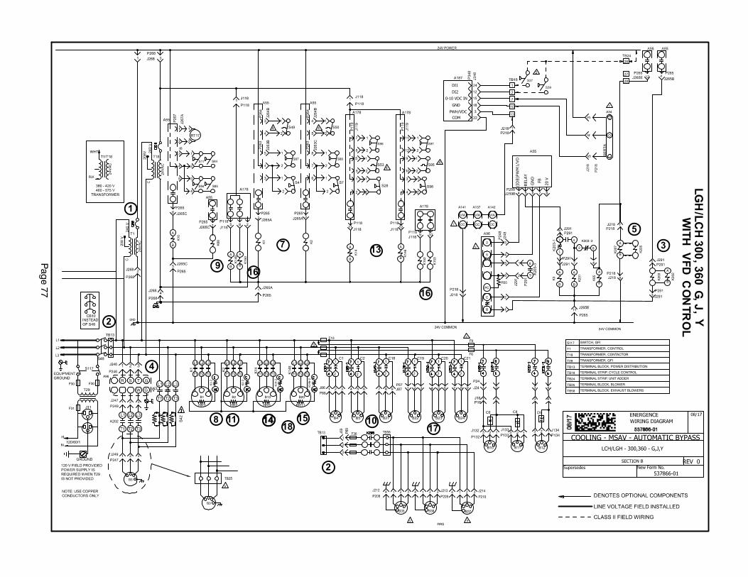
Pag
e 7
7
GND
B2 B20B1
F10
B13
F30
F31
K14
9A
B
K15
0
A
B
K10
A
B K68 K2
K1
K20
3
K20
7
A
B
20 VFBD
NG
YA
LE
R
K65
A
B
24V COMMON
7
K20
2
A
B
+
O
−
A34
7
VIA
A137
CC
VIA
A141
CC
VIA
A142
CC
BLK
C
B
2
5
6
9
K15
3
K15
2
K14
A
B
K14
6
A
B
F6
F6
OV/
1M
WP)
BD I(
K3
A
B
K23
1
A
B
7
1
4
82
K203−2
6
8RRS
T1 TRANSFORMER, CONTROL
T18 TRANSFORMER, CONTACTOR
T29 TRANSFORMER, GFI
TB13 TERMINAL BLOCK, POWER DISTRIBUTION
TB24 TERMINAL STRIP, UNIT ADDER
TB25 TERMINAL BLOCK, BLOWER
3
F30
PWH/VDC
0-10 VDC IN
GND
COM
DI2
DI1
K1-2
K2-2
K14-2
K146-2
TB18 TERMINAL STRIP, CYCLE CONTROL
5
PC
R55
B3
R S T
W V U
G
G
A96
TB58 TERMINAL BLOCK, EXHAUST BLOWERS
B3
9
K20
5
S117 SWITCH, GFI
COOLING - MSAV - AUTOMATIC BYPASS
REV 0
1
2
2
3
4
5
7
8
9
1011`
13
1414 15
16
16
1718

Pag
e 7
8
COOLING - MSAV - AUTOMATIC BYPASS
REV 0
S42 USED ON UNITS WITH VFD CONTROL WITHBYPASS OPTION, UNITS WITH HIGHEFFICIENCY MOTORS AND UNITS WITHMOTORS LESS INTERNAL OVERLOADPROTECTION
F6 AND F10 FUSES ARE USED ON ”Y”VOLTAGE UNITS ONLY
S49,S50,S53 AND S95 ARE A PART OF5VDC CIRCUIT
FOR P.E. INVERTER WIRING, REFER TORRS ASSEMBLY
A34 SENSOR AND A137, A141, A142INVERTER CONTROL FOR B35, B36,B37 EXHAUST AIR BLOWER (RRS)
TB25 USED IN PLACE OF P247/J249ON Y VOLT UNITS
NOTES
B37 BLOWER MAY NOT BE USED
18 EXHAUST FAN COMP
24 EXHAUST FAN
86 OUTDOOR FAN INTERFACE
87 OUTDOOR FAN INTERFACE 2
118 CONTROL FOR COMPRESSOR 3 AND 4
119 COMPRESSOR 3 AND 4, INPUT
132 EXHAUST FAN MOTOR 1
133 EXHAUST FAN MOTOR 2
134 EXHAUST FAN MOTOR 3
246 POWER TO VFD
247 VFD TO MOTOR
248 VFD TO CONTROL
249 CONTACTOR BYPASS
263 HIGH AND LOW PRESSURE SWITCHES
264 BLOWER DECK
265 CONTACTORS AND RELAYS
268 24V POWER FROM TRANSFORMERS
J/P JACK/PLUG DESCRIPTION
218 POWER EXHAUST CONTROL
291 VFD BYPASS LOW VOLTAGE
259 BLOWER ECM MOTOR
69 INTERFACE
209 MOTOR, EXH BLO, B36
210 MOTOR, EXH BLO, B37
212
213
214
208 MOTOR, EXH BLO, B35
MOTOR, EXH BLO, B36
MOTOR, EXH BLO, B37
MOTOR, EXH BLO, B35
348 CONTROL, GENERAL PURPOSE GP3
11 GFI, RECEPTACLE
KEY COMPONENT
A34 DIFFERENTIAL PRESSURE TRANSDUCER
A55 CONTROL BOARD, MAIN
A96 CONTROL INVERTER
A142 INVERTER, EXHAUST 3
B1 COMPRESSOR 1
B2 COMPRESSOR 2
B3 MOTOR, BLOWER
B4 MOTOR, OUTDOOR FAN 1
B5 MOTOR, OUTDOOR FAN 2
B10 MOTOR, EXHAUST FAN 1
B11 MOTOR, EXHAUST FAN 2
B12 MOTOR, EXHAUST FAN 3
B13 COMPRESSOR 3
B20 COMPRESSOR 4
B21 MOTOR, OUTDOOR FAN 3
B22 MOTOR, OUTDOOR FAN 4
B23 MOTOR, OUTDOOR FAN 5
B24 MOTOR, OUTDOOR FAN 6
C1 CAPACITOR, OUTDOOR FAN 1
C2 CAPACITOR, OUTDOOR FAN 2
C6 CAPACITOR, EXHAUST FAN 1
C8 CAPACITOR, EXHAUST FAN 2
C9 CAPACITOR, EXHAUST FAN 3
C18 CAPACITOR, OUTDOOR FAN 3
C19 CAPACITOR, OUTDOOR FAN 4
C20 CAPACITOR, OUTDOOR FAN 5
C21 CAPACITOR, OUTDOOR FAN 6
CB8 CIRCUIT, BREAKER T1
CB10 CIRCUIT BREAKER, MAIN DISCONNECT UNIT
CB18 CIRCUIT, BREAKER T18
F6 FUSE, EXHAUST FAN
F10 FUSE, OUTDOOR FAN MOTOR
F30 FUSE, TRANSFORMER T29 PRIMARY
F31 FUSE, TRANSFORMER T29 SECONDARY
A137 INVERTER, EXHAUST 1
A141 INVERTER, EXHAUST 2
A187 CONTROL, GENERAL PURPOSE GP3
A178 CONTROL BOARD, COMP 3 & 4, 2ND STAGE HEAT
F36 FUSE,P.E. BLOWERS
B37 MOTOR, EXH, BLO 3
B36 MOTOR, EXH, BLO 2
B35 MOTOR, EXH, BLO 1
HR1 HEATER COMPRESSOR 1
HR2 HEATER COMPRESSOR 2
HR5 HEATER COMPRESSOR 3
HR11 HEATER COMPRESSOR 4
K1 CONTACTOR, COMPRESSOR 1
K2 CONTACTOR, COMPRESSOR 2
K3 CONTACTOR, BLOWER
K10 RELAY, OUTDOOR FAN 1
K14 CONTACTOR, COMPRESSOR 3
K65 RELAY, EXHAUST FAN
K68 RELAY, OUTDOOR FAN 2
K146 CONTACTOR, COMPRESSOR 4
K149 RELAY, OUTDOOR FAN 3
K150 RELAY, OUTDOOR FAN 4
K152 RELAY, OUTDOOR FAN 5
K153 RELAY, OUTDOOR FAN 6
K203 RELAY INVERTER CONTROL
K207 RELAY, EXHAUST BLOWER
RT17 SENSOR, OUTDOOR AIR
S4 SWITCH, LIMIT HI PRESS COMPRESS 1
S7 SWITCH, LIMIT HI PRESS COMPRESS 2
S11 SWITCH, LOW PRESS, LOW AMBIENT COMP 1
S31 SWITCH, LIMIT HI TEMP COMPRESSOR 3
S42 SWITCH, OVERLOAD RELAY BLOWER MOTOR
S48 SWITCH, DISCONNECT
S49 SWITCH, FREEZE STAT COMPRESS 1
S50 SWITCH, FREEZE STAT COMPRESS 2
S53 SWITCH, FREEZE STAT COMPRESS 3
S84 SWITCH, LOW PRESS, LOW AMBIENT COMP 2
S85 SWITCH, LOW PRESS, LOW AMBIENT COMP 3
S87 SWITCH, LOW PRESS, COMP 1
S88 SWITCH, LOW PRESS, COMP 2
S94 SWITCH, LOW PRESS, LOW AMBIENT KIT COMP 4
S95 SWITCH, FREEZE STAT COMPRESS 4
S96 SWITCH, LIMIT HI PRESS COMPRESS 4
S97 SWITCH, LOW PRESS, COMP 4
S98 SWITCH, LOW PRESS, COMP 3
K231 RELAY, EXHAUST FAN 2
K202 CONTACTOR, INVERTER
S37 SWITCH, PRESS, EXH
S39 SWITCH, EXHAUST FAN
R55 RESISTOR, VFD LOADING, A96
K205 CONTACTOR,POWER EXHAUST
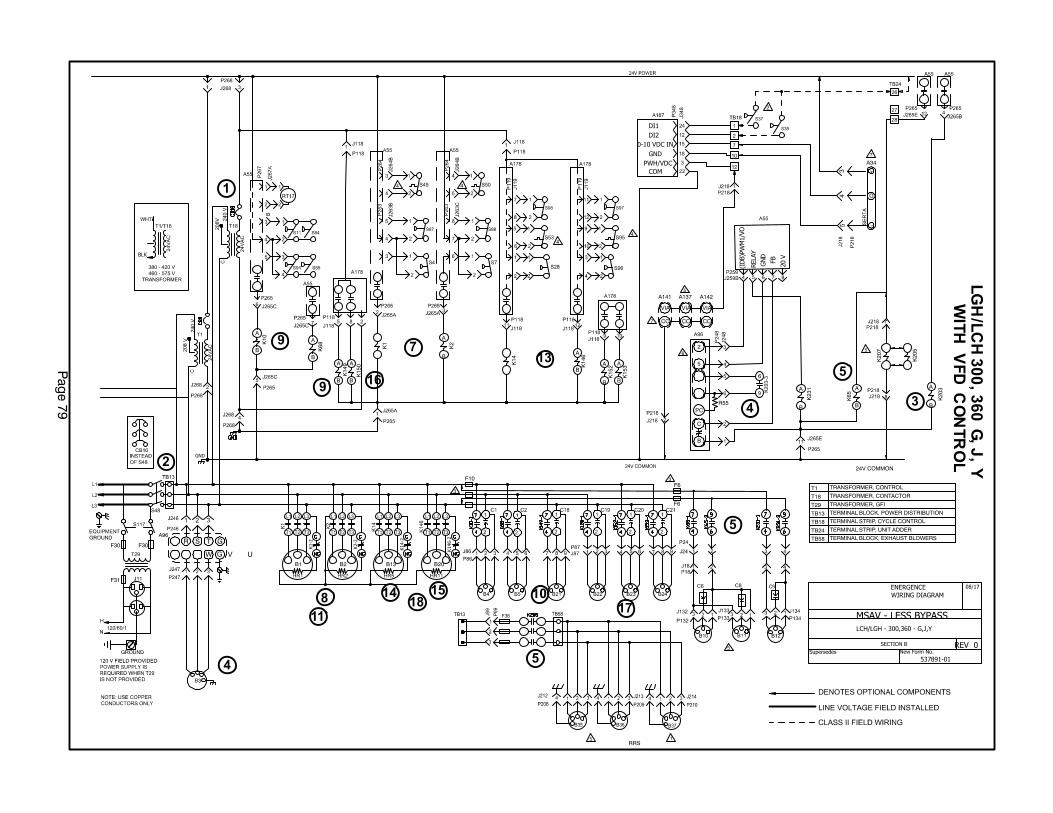
Pag
e 7
9
GND
B2 B20B1
F10
B13
F30
F31
K14
9A
B
K15
0A
B
K10
A
B K68
A
B
K2
A
B
K1
K20
3A
B
K20
7
V0
2
FBD
NG
YA L
ER
K65
A
B
24V COMMON
7
+
O
−
A34
7
VIA
A137
CC
VIA
A141
CC
VIA
A142
CC
BLK
C
B
2
5
6
9
K15
3A
B
K15
2A
B
K14
K14
6A
B
F6
F6
OV/
1M
WP)
BDI(
K23
1A
B
6
1RRS
T1 TRANSFORMER, CONTROL
T18 TRANSFORMER, CONTACTOR
T29 TRANSFORMER, GFI
TB13 TERMINAL BLOCK, POWER DISTRIBUTION
TB24 TERMINAL STRIP, UNIT ADDER
3
F30
PWH/VDC
0-10 VDC IN
GND
COM
DI2
DI1
K1-2
K2-2
K14-2
K146-2
TB18 TERMINAL STRIP, CYCLE CONTROL
5
PCR55
B3
R S T
W V U
G
G
A96TB58 TERMINAL BLOCK, EXHAUST BLOWERS
K20
55
5
1
2
3
4
4
5
5
7
8
9
9
10
5
11`
13
14 1518
16
17MSAV - LESS BYPASS
REV 0
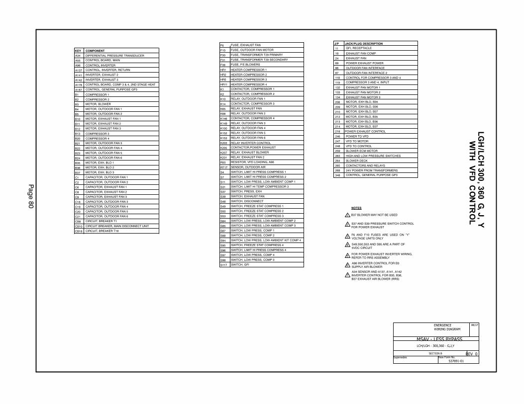
Pag
e 8
0
18 EXHAUST FAN COMP
24 EXHAUST FAN
86 OUTDOOR FAN INTERFACE
87 OUTDOOR FAN INTERFACE 2
118 CONTROL FOR COMPRESSOR 3 AND 4
119 COMPRESSOR 3 AND 4, INPUT
132 EXHAUST FAN MOTOR 1
133 EXHAUST FAN MOTOR 2
134 EXHAUST FAN MOTOR 3
246 POWER TO VFD
247 VFD TO MOTOR
248 VFD TO CONTROL
263 HIGH AND LOW PRESSURE SWITCHES
264 BLOWER DECK
265 CONTACTORS AND RELAYS
268 24V POWER FROM TRANSFORMERS
J/P JACK/PLUG DESCRIPTION
218 POWER EXHAUST CONTROL
259 BLOWER ECM MOTOR
69 POWER EXHAUST POWER
209 MOTOR, EXH BLO, B36
210 MOTOR, EXH BLO, B37
212
213
214
208 MOTOR, EXH BLO, B35
MOTOR, EXH BLO, B36
MOTOR, EXH BLO, B37
MOTOR, EXH BLO, B35
348 CONTROL, GENERAL PURPOSE GP3
11 GFI, RECEPTACLE
S37 AND S39 PRESSURE SWITCH CONTROLFOR POWER EXHAUST
F6 AND F10 FUSES ARE USED ON ”Y”VOLTAGE UNITS ONLY
S49,S50,S53 AND S95 ARE A PART OF5VDC CIRCUIT
FOR POWER EXHAUST INVERTER WIRING,REFER TO RRS ASSEMBLY
A96 INVERTER CONTROL FOR B3SUPPLY AIR BLOWER
A34 SENSOR AND A137, A141, A142INVERTER CONTROL FOR B35, B36,B37 EXHAUST AIR BLOWER (RRS)
NOTES
B37 BLOWER MAY NOT BE USED
KEY COMPONENT
A34 DIFFERENTIAL PRESSURE TRANSDUCER
A55 CONTROL BOARD, MAIN
A96 CONTROL INVERTER
A142 INVERTER, EXHAUST 3
B1 COMPRESSOR 1
B2 COMPRESSOR 2
B3 MOTOR, BLOWER
B4 MOTOR, OUTDOOR FAN 1
B5 MOTOR, OUTDOOR FAN 2
B10 MOTOR, EXHAUST FAN 1
B11 MOTOR, EXHAUST FAN 2
B12 MOTOR, EXHAUST FAN 3
B13 COMPRESSOR 3
B20 COMPRESSOR 4
B21 MOTOR, OUTDOOR FAN 3
B22 MOTOR, OUTDOOR FAN 4
B23 MOTOR, OUTDOOR FAN 5
B24 MOTOR, OUTDOOR FAN 6
C1 CAPACITOR, OUTDOOR FAN 1
C2 CAPACITOR, OUTDOOR FAN 2
C6 CAPACITOR, EXHAUST FAN 1
C8 CAPACITOR, EXHAUST FAN 2
C9 CAPACITOR, EXHAUST FAN 3
C18 CAPACITOR, OUTDOOR FAN 3
C19 CAPACITOR, OUTDOOR FAN 4
C20 CAPACITOR, OUTDOOR FAN 5
C21 CAPACITOR, OUTDOOR FAN 6
CB8 CIRCUIT, BREAKER T1
CB10 CIRCUIT BREAKER, MAIN DISCONNECT UNIT
CB18 CIRCUIT, BREAKER T18
A137 CONTROL, INVERTER, RETURN
A141 INVERTER, EXHAUST 2
A187 CONTROL, GENERAL PURPOSE GP3
A178 CONTROL BOARD, COMP 3 & 4, 2ND STAGE HEAT
B37 MOTOR, EXH, BLO 3
B36 MOTOR, EXH, BLO 2
B35 MOTOR, EXH, BLO 1
F6 FUSE, EXHAUST FAN
F10 FUSE, OUTDOOR FAN MOTOR
F30 FUSE, TRANSFORMER T29 PRIMARY
F31 FUSE, TRANSFORMER T29 SECONDARY
HR1 HEATER COMPRESSOR 1
HR2 HEATER COMPRESSOR 2
HR5 HEATER COMPRESSOR 3
HR11 HEATER COMPRESSOR 4
K1 CONTACTOR, COMPRESSOR 1
K2 CONTACTOR, COMPRESSOR 2
K10 RELAY, OUTDOOR FAN 1
K14 CONTACTOR, COMPRESSOR 3
K65 RELAY, EXHAUST FAN
K68 RELAY, OUTDOOR FAN 2
K146 CONTACTOR, COMPRESSOR 4
K149 RELAY, OUTDOOR FAN 3
K150 RELAY, OUTDOOR FAN 4
K152 RELAY, OUTDOOR FAN 5
K153 RELAY, OUTDOOR FAN 6
K203 RELAY INVERTER CONTROL
K207 RELAY, EXHAUST BLOWER
RT17 SENSOR, OUTDOOR AIR
S4 SWITCH, LIMIT HI PRESS COMPRESS 1
S7 SWITCH, LIMIT HI PRESS COMPRESS 2
S11 SWITCH, LOW PRESS, LOW AMBIENT COMP 1
S31 SWITCH, LIMIT HI TEMP COMPRESSOR 3
S48 SWITCH, DISCONNECT
S49 SWITCH, FREEZE STAT COMPRESS 1
S50 SWITCH, FREEZE STAT COMPRESS 2
S53 SWITCH, FREEZE STAT COMPRESS 3
S84 SWITCH, LOW PRESS, LOW AMBIENT COMP 2
S85 SWITCH, LOW PRESS, LOW AMBIENT COMP 3
S87 SWITCH, LOW PRESS, COMP 1
S88 SWITCH, LOW PRESS, COMP 2
S94 SWITCH, LOW PRESS, LOW AMBIENT KIT COMP 4
S95 SWITCH, FREEZE STAT COMPRESS 4
S96 SWITCH, LIMIT HI PRESS COMPRESS 4
S97 SWITCH, LOW PRESS, COMP 4
S98 SWITCH, LOW PRESS, COMP 3
S117 SWITCH, GFI
K231 RELAY, EXHAUST FAN 2
F36 FUSE, P.E.BLOWERS
S37 SWITCH, PRESS, EXH
S39 SWITCH, EXHAUST FAN
R55 RESISTOR, VFD LOADING, A96
K205 CONTACTOR,POWER EXHAUST
MSAV - LESS BYPASS
REV 0
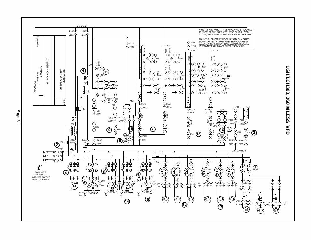
Pag
e 8
1
24V COMMON
NOTE - IF ANY WIRE IN THIS APPLIANCE IS REPLACEDIT MUST BE REPLACED WITH WIRE OF LIKE SIZE,RATING, TERMINATION AND INSULATION THICKNESS.
WARNING - ELECTRIC SHOCK HAZARD, CAN CAUSEINJURY OR DEATH . UNIT MUST BE GROUNDED INACCORDANCE WITH NATIONAL AND LOCAL CODES.DISCONNECT ALL POWER BEFORE SERVICING.
K14
9A
B
K15
0
K15
3
K15
2
K10K68
A
B
K2
K14A
B
K1A
B
K14
6A
B
K3
A
B
K65
S176
95
96
S177
95
96
S178
95
96
S179 95
96
F10F6
F1
F18
24 V POWER
1
2
33
4
5
57
8
9
10
13
9
14 15
1616
17

Pag
e 8
2
J/P JACK/PLUG DESCRIPTION
A55 CONTROL BOARD, MAIN
CONTROL BOARD, COMP 3 & 4, 2ND STAGE HEAT
B1 COMPRESSOR 1
B2 COMPRESSOR 2
B3 MOTOR, BLOWER
B4 MOTOR, OUTDOOR FAN 1
B5 MOTOR, OUTDOOR FAN 2
B10 MOTOR, EXHAUST FAN 1
B11 MOTOR, EXHAUST FAN 2
B13
COMPRESSOR 4
B21 MOTOR, OUTDOOR FAN 3
B22 MOTOR, OUTDOOR FAN 4
B23 MOTOR, OUTDOOR FAN 5
B24 MOTOR, OUTDOOR FAN 6
C1 CAPACITOR, OUTDOOR FAN 1
C2 CAPACITOR, OUTDOOR FAN 2
C6 CAPACITOR, EXHAUST FAN 1
C8 CAPACITOR, EXHAUST FAN 2
C18 CAPACITOR, OUTDOOR FAN 3
C19 CAPACITOR, OUTDOOR FAN 4
C20 CAPACITOR, OUTDOOR FAN 5
C21 CAPACITOR, OUTDOOR FAN 6
CB8 CIRCUIT, BREAKER T1
CB18 CIRCUIT, BREAKER T18
HR1 HEATER COMPRESSOR 1
HR2
HEATER COMPRESSOR 3
HR11 HEATER COMPRESSOR 4K1,−1 CONTACTOR, COMPRESSOR 1
K2,−1
CONTACTOR, BLOWER
K10,−1,2
RELAY, EXHAUST FAN
K68,−1
RELAY, OUTDOOR FAN 3
K150,−1
RELAY, OUTDOOR FAN 6
18 EXHAUST FAN COMP
24 EXHAUST FAN
86
COMPRESSOR 3 AND 4, CONTROL
119 COMPRESSOR 3 AND 4, INPUT
132
EXHAUST FAN MOTOR 2
134
BLOWER DECK
265
T1 TRANSFORMER
310 CRANKCASE HEATERS
RT17 SENSOR, OUTDOOR AIR
S4 SWITCH, LIMIT HI PRESS COMPRESS 1
S7 SWITCH, LIMIT HI PRESS COMPRESS 2
S11 SWITCH, LOW PRESS, LOW AMBIENT COMP 1
S28 SWITCH, LIMIT HI PRESS COMPRESS 3
S42 SWITCH, OVERLOAD RELAY BLOWER MOTOR
S48 SWITCH, DISCONNECT
S49 SWITCH, FREEZE STAT COMPRESS 1
S50 SWITCH, FREEZE STAT COMPRESS 2
S53 SWITCH, FREEZE STAT COMPRESS 3
S94 SWITCH, LOW PRESS, LOW AMBIENT KIT COMP 4
S95 SWITCH, FREEZE STAT COMPRESS 4
S96 SWITCH, LIMIT HI PRESS COMPRESS 4
S97 SWITCH, LOW PRESS, COMP 4
S98 SWITCH, LOW PRESS, COMP 3
S176 SWITCH, OVERLOAD COMPRESSOR 1
S177 SWITCH, OVERLOAD COMPRESSOR 2
S178 SWITCH, OVERLOAD COMPRESSOR 3
S179 SWITCH, OVERLOAD COMPRESSOR 4
T1 TRANSFORMER, CONTROL
T18 TRANSFORMER, CONTACTOR
TB13 TERMINAL STRIP, POWER DISTRIBUTION
S49,S50,S53 AND S95 ARE PART OF 5VDCCIRCUIT
KEY COMPONENT DESCRIPTIONS84 SWITCH, LOW PRESS, LOW AMBIENT KIT COMP 2
S85 SWITCH, LOW PRESS, LOW AMBIENT KIT COMP 3
S87 SWITCH, LOW PRESS, COMP 1
S88 SWITCH, LOW PRESS, COMP 2
F1 FUSE, TRANSFORMER, T1
F6 FUSE, EXHAUST FAN
F10 FUSE, OUTDOOR FAN MOTOR
F18 FUSE, TRANSFORMER, T18
C9 CAPACITOR, EXHAUST FAN 3
B12 MOTOR, EXHAUST FAN 3
A178
COMPRESSOR 3
B20
HEATER COMPRESSOR 2
HR5
CONTACTOR, COMPRESSOR 2
K3-1
RELAY, OUTDOOR FAN 1
K14-01 CONTACTOR, COMPRESSOR 3
K65-1,2
RELAY,OUTDOOR FAN 2
K146-1 CONTACTOR, COMPRESSOR 4
K149-1
RELAY, OUTDOOR 4
RELAY, OUTDOOR 5K152-1
K153-1, -2
87
OUTDOOR FAN INTERFACE
OUTDOOR FAN INTERFACE 2
118
EXHAUST FAN MOTOR 1
133
EXHAUST FAN MOTOR 3
HIGH AND LOW PRESSURE SWITCHES263
264
CONTACTORS AND RELAYS
OUTDOOR FAN AREA267
268

Pag
e 8
3
POWER:
1- Line voltage from TB2, unit disconnect S48, or other factory or field in
stalled optional power disconnects, such as CB10, energizes transformer
T1 and T18. Transformer T1 provides 24VAC power to the A55 Unit Con
troller and T18 provides 24VAC power to A178 Compressor 3 and 4 Con
troller. The two controllers provide 24VAC power to the unit cooling, heat
ing and blower controls and thermostat.
2- Terminal block TB13 is also energized when the unit disconnect closes.
TB13 supplies line voltage to compressor crankcase heaters, com
pressors, blower motors and fan motors.
BLOWER OPERATION (OCP INPUT MUST BE ON):
3- The A55 Unit Controller receives a demand from thermostat terminal G.
A55 energizes blower contactor K3 with 24VAC. On VFD units, A55 en
ergizes relay K203.
4- N.O. K3‐1 closes, energizing blower B3. On VFD units, N.O. K203-2 clos
es, sending a signal to the inverter, A96, to start forward rotation. P259 pin
#4 sends a 0 -10VDC signal to A96 to control blower B3 speed.
POWER EXHAUST FANS/BLOWERS:
5- The A55 Unit Controller receives a demand and energizes exhaust fan
relay K65 OR exhaust blower contactor K205 or exhaust blower relay
K207.
1ST STAGE COOLING (BOTH COMPRESSORS B1 AND B2 ARE ENER
GIZED):
6- First stage cooling demand energizes Y1 and G in the thermostat. G ener
gizes blower, if blower is not already running (see step 3).
7- 24VAC is routed to the A55 Unit Controller. After A55 proves N.C. low
pressure switch S87 and S88, N.C. freezestat S49 and S50 and N.C.
high pressure switch S4 and S7, compressor contactors K1 and K2
are energized.
8- N.O. contacts K1-1 and K2-1 close energizing compressor B1 and B2.
9- A55 Unit Controller and A178 Controller energize fan contactor K10,
K68, and K149 based on low ambient switch S11 and S84 inputs and
predefined control logic.
10-N.O. contact K10-1, K68-1, K149-1 close energizing fan B4, B5 and B21
respectively.
11- N.C. Contacts K1-2 and K2-2 open de-energizing compressor 1 and 2
crankcase heater HR1 and HR2.
2ND STAGE COOLING:
12- Second stage cooling demand energizes Y2.
13-24VAC is routed to A178 Compressor 3 and 4 Controller. After A178
proves N.C. low pressure switches S98 and S97, N.C. freezestats
S53 and S95 and N.C. high pressure switches S28 and S96, com
pressor contactors K14 and K146 are energized.
14- N.O. contacts K14-1 close energizing compressor B13.
15- N.O. contacts K146-1 close energizing compressor B20.
16- A178 Controller energizes fan contactor K150, K152, K153 based on
low ambient switch S85 and S94 inputs and predefined control logic.
17-N.O. contacts K150-1, K152-1 and K153-1 close energizing con
denser fan B22, B23 and B24 respectively.
18-N.C contacts K14-2 and K146-2 open de-energizing compressor 3
and 4 crankcase heater HR5 and HR11.
Sequence of Operation LGH/LCH242/300/360
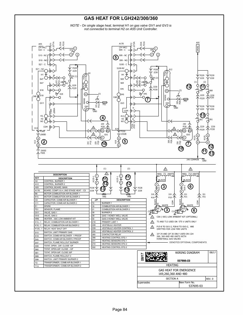
Page 84
GAS HEAT FOR LGH242/300/360
NOTE - On single stage heat, terminal H1 on gas valve GV1 and GV3 isnot connected to terminal H2 on A55 Unit Controller.
2
4
510 7
11
12
11
12
11
13
3 6
10
HEATING
REV. 0
BLACK
HI
CO
M
WHITE
T3
2
1
B6
C3
HR6
(2)
K125-1
7
4
J19 1
K13-1
7
4
P19
S99
J216
4
6
P216
J19 2
P19
J28
9
P28
BLACK
HI
CO
M
WHITE
T13
B15
C11
J211
K19-1
7
4
P21
J212P21HR6
K125-1 7
4
(1) 2
P28
J28
4
3
S69
KEY DESCRIPTIONA3 CONTROL, BURNER 1
A12 CONTROL, BURNER 2
A55
3
B6 MOTOR COMBUSTION AIR BLOWER 1
B15 MOTOR COMBUSTION AIR BLOWER 2
C3 CAPACITOR, COMB AIR BLOWER 1
C11 CAPACITOR, COMB AIR BLOWER 2
E1 SPARK
FS1 SENSOR, FLAME
GV1 VALVE, GAS 1
GV3 VALVE, GAS 2
HR6 HEATER, −50C LOW AMBIENT KIT
K13,−1 RELAY, COMBUSTION AIR BLOWER 1
K19,−1 RELAY, COMBUSTION AIR BLOWER 2
K125,−1 RELAY, HEAT SHUT OFF
S10 SWITCH, LIMIT PRIMARY GAS
S18 SWITCH, COMB AIR BLOWER 1 PROOF
S45 SWITCH, COMB AIR BLOWER 2 PROOF
S47 SWITCH, FLAME ROLLOUT BURNER
S59 TSTAT, OPEN −20F, CLOSE 10F
S60 TSTAT, OPEN 20F, CLOSE −10F
S61 TSTAT, OPEN 50F, CLOSE 20F
S69 SWITCH, FLAME ROLLOUT 2
S99 SWITCH, LIMIT PRIMARY BURNER 2
T3 TRANSFORMER, COMB AIR BLOWER 1
1
2
3
2
3
4
5
6
9
8
10
COM
K19
B
2
A
1
1
CONTROL BOARD, MAIN
A12,
H2
(24 VAC)
S99 - C
S100-NC
S69
S99 - NC
S99 - NO
S100 - C
S69
S45
GV3
S45
CAB
3
A178
5
K13
A
B
E1
FS1
GND
2
3
4
5
6
7
9
8
10
1
(24 VAC)
S10 - C
2
1
3
COM
W2
A3,
K13
H2
CAB
A55
J265D8P265
W2
GV1
S18
P15
J15
4
3
K19
A
B
8
J15
9
7
GV3
S10
J216
1
3
P216
2
E1
FS1
GND
8
7
A12
J28
5
P28
A3
J15
5
P15
3
K125 A
B
S60
S61
S60
S61
(2)
K125 A
B
P229
J2294P230
J2304
P229
J229
P230
J230
P229
J2292P230J2302
P229
J2291
P230
J2301S59 (1)
J2296
P229
P229
J2295
S59 (2)
J2306
P230
P230
J2305
P228
J2281
P228
J22822 1
(1)
DESCRIPTION
A178 BOARD, COMP 3 & 4, 2ND STAGE HEAT − C3
15 BURNER 1
19 COMBUSTION AIR BLOWER 1
21 COMBUSTION AIR BLOWER 2
28 BURNER 2
216 PRIMARY LIMIT 1
228 VESTIBULE HEATER
229 VESTIBULE HEATER CONTROL 1
230 VESTIBULE HEATER CONTROL 2
265 CONTACTOR RELAY
266 HEATING CONTROL STG 1
271 HEATING SENSORS STG 1
272 HEATING SENSORS STG 2
J/P DESCRIPTION
S45
332 HEATING CONTROL STG 2
T13 TRANSFORMER, COMB AIR BLOWER 2
S47
J29
1
2
J29 3
J30
1
2
J30 3
4 4
29 GAS 1 HONEY WELL VALVE
30 GAS 2 HONEY WELL VALVE
4
24VAC
A55
24V COMMONGND
3
5
6
7
11
13
13
12
13
12
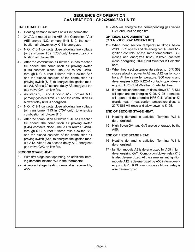
Page 85
SEQUENCE OF OPERATIONGAS HEAT FOR LGH242/300/360 UNITS
FIRST STAGE HEAT:
1 - Heating demand initiates at W1 in thermostat.
2 - 24VAC is routed to the A55 Unit Controller. After
A55 proves N.C. primary limit S10, the com
bustion air blower relay K13 is energized.
3 - N.O. K13‐1 contacts close allowing line voltage
(or transformer T3 in 575V only) to energize com
bustion air blower B6.
4 - After the combustion air blower B6 has reached
full speed, the combustion air proving switch
(S18) contacts close. The A55 routes 24VAC
through N.C. burner 1 flame rollout switch S47
and the closed contacts of the combustion air
proving switch (S18) to energize the ignition mod
ule A3. After a 30 second delay A3 energizes the
gas valve GV1 on low fire.
5 - As steps 2, 3 and 4 occur, A178 proves N.C.
primary gas heat limit S99 and the combustion air
blower relay K19 is energized.
6 - N.O. K19‐1 contacts close allowing line voltage
(or transformer T13 in 575V only) to energize
combustion air blower B15.
7 - After the combustion air blower B15 has reached
full speed, the combustion air proving switch
(S45) contacts close. The A178 routes 24VAC
through N.C. burner 2 flame rollout switch S69
and the closed contacts of the combustion air
proving switch (S45) to energize the ignition mod
ule A12. After a 30 second delay A12 energizes
gas valve GV3 on low fire.
SECOND STAGE HEAT:
8 - With first stage heat operating, an additional heat
ing demand initiates W2 in the thermostat.
9 - A second stage heating demand is received by
A55.
10 - A55 will energize the corresponding gas valves
GV1 and GV3 on high fire.
OPTIONAL LOW AMBIENT KIT(C.G.A. ‐50°C LOW AMBIENT KIT):
11 - When heat section temperature drops below
-20°F, S59 opens and de-energized A3 and A12
ignition controls. At the same temperature, S60
closes and energizes K125. K125-1 contacts
close energizing HR6 Cold Weather Kit electric
heat.
12 - When heat section temperature rises to 10°F, S59
closes allowing power to A3 and A12 ignition con
trols. At the same temperature, S60 opens and
de-energizes K125. K125-1 contacts open de-en
ergizing HR6 Cold Weather Kit electric heat.
13 - If heat section temperature rises above 50°F, S61
will open and de-energize K125. K125-1 contacts
will open and de-energize HR6 Cold Weather Kit
electric heat. If heat section temperature drops to
20°F, S61 will close and allow power to K125.
END OF SECOND STAGE HEAT:
14 - Heating demand is satisfied. Terminal W2 is
de‐energized.
15 - High fire on GV1 and GV3 are de‐energized by the
A55.
END OF FIRST STAGE HEAT:
16 - Heating demand is satisfied. Terminal W1 is
de‐energized.
17 - Ignition module A3 is de‐energized by A55 in turn
de‐energizing GV1. Combustion blower relay K13
is also de‐energized. At the same instant, ignition
module A12 is de‐energized by A55 in turn de‐en
ergizing GV3. K19 combustion air blower relay is
also de‐energized.
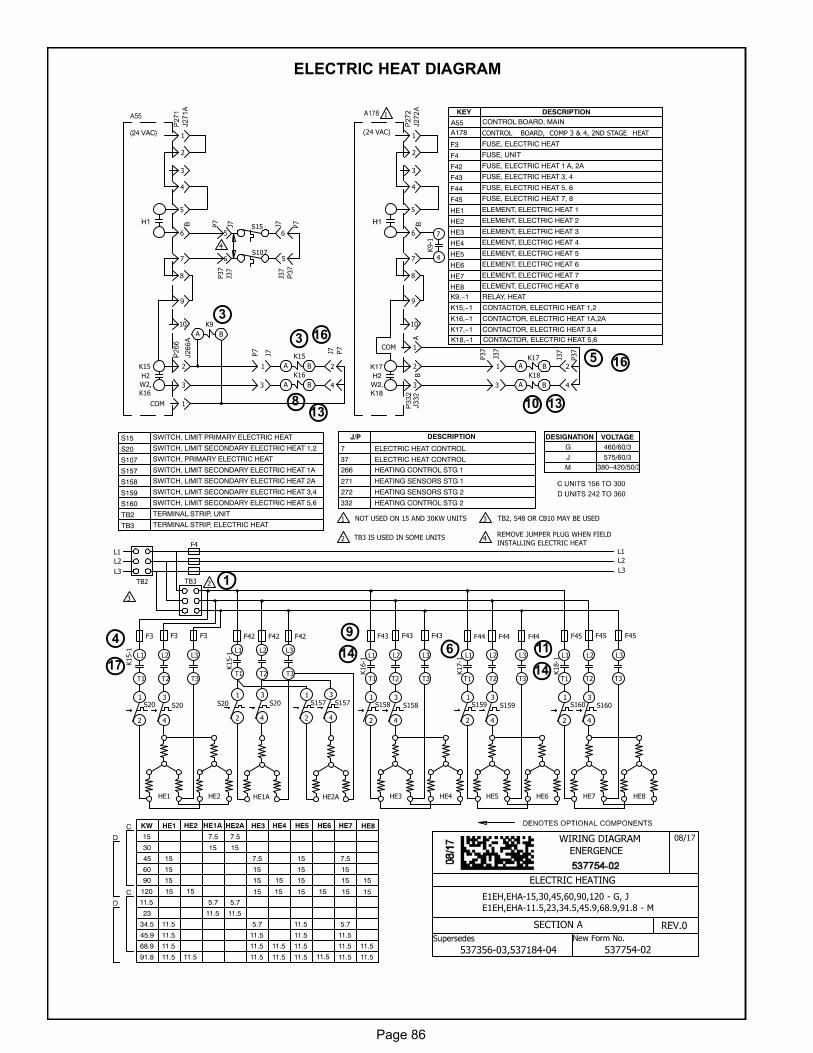
Page 86
ELECTRIC HEAT DIAGRAM
11
5
8
17
6
3
10
3
4
16
13
14
9
E1EH,EHA-15,30,45,60,90,120 - G, J
E1EH,EHA-11.5,23,34.5,45.9,68.9,91.8 - M
ELECTRIC HEATING
1
2 4
3NOT USED ON 15 AND 30KW UNITS
TB3 IS USED IN SOME UNITS REMOVE JUMPER PLUG WHEN FIELD
INSTALLING ELECTRIC HEAT
TB2, S48 OR CB10 MAY BE USED
KW HE1 HE2 HE1A HE2A HE3 HE4 HE5 HE6 HE7 HE8
15 7.5 7.5
30 15 15
45 15 7.5 15 7.5
60 15 15 15 15
90 15 15 15 15 15 15
L2
L1 L1
L2
L3L3
F4
TB2 TB3 2
F45
HE7
F45 F45
HE8
S1601
2
S1603
4
F43
HE3
F43 F43
HE4
S1581
2
S1583
4
F44 F44 F44
HE2A
F42
HE1A
F42 F42
S20
1
2
S203
4
S1571
2
S1573
4
F3
HE1
F3 F3
HE2
S201
2
S203
4
HE5 HE6
S1591
2
S1593
4
K15-1
L1
T1
L2
T2
L3
T3
K15-1
L1
T1
L2
T2
L3
T3 K16-1
L1
T1
L2
T2
L3
T3
K17-1
L1
T1
L2
T2
L3
T3
K18-1
L1
T1
L2
T2
L3
T3
3
P7
J75
P37
J37
6S107
S15 J7
6
J37
5
P7
P7
J7
1
3
P37
J37
1
3
K9-1
7
4
KEY DESCRIPTION
A55
F3 FUSE, ELECTRIC HEAT
F4 FUSE, UNIT
F42 FUSE, ELECTRIC HEAT 1 A, 2A
F43 FUSE, ELECTRIC HEAT 3, 4
F44 FUSE, ELECTRIC HEAT 5, 6
F45 FUSE, ELECTRIC HEAT 7, 8
HE1 ELEMENT, ELECTRIC HEAT 1
HE2 ELEMENT, ELECTRIC HEAT 2
HE3 ELEMENT, ELECTRIC HEAT 3
HE4 ELEMENT, ELECTRIC HEAT 4
HE5 ELEMENT, ELECTRIC HEAT 5
HE6 ELEMENT, ELECTRIC HEAT 6
HE7 ELEMENT, ELECTRIC HEAT 7
HE8 ELEMENT, ELECTRIC HEAT 8
K9,−1 RELAY, HEAT
K15,−1 CONTACTOR, ELECTRIC HEAT 1,2
K16,−1 CONTACTOR, ELECTRIC HEAT 1A,2A
K17,−1 CONTACTOR, ELECTRIC HEAT 3,4
K18,−1 CONTACTOR, ELECTRIC HEAT 5,6
S15 SWITCH, LIMIT PRIMARY ELECTRIC HEAT
S20 SWITCH, LIMIT SECONDARY ELECTRIC HEAT 1,2
S107 SWITCH, PRIMARY ELECTRIC HEAT
S157 SWITCH, LIMIT SECONDARY ELECTRIC HEAT 1A
S158 SWITCH, LIMIT SECONDARY ELECTRIC HEAT 2A
S159 SWITCH, LIMIT SECONDARY ELECTRIC HEAT 3,4
S160 SWITCH, LIMIT SECONDARY ELECTRIC HEAT 5,6
TB2 TERMINAL STRIP, UNIT
TB3 TERMINAL STRIP, ELECTRIC HEAT
P37
J37
2
4
P7
J7
2
4
2
3
4
5
6
7
8
10
1
CONTROL BOARD, MAIN
2
1
3
COM
K15
W2,
K16
H2
2
3
4
5
6
7
9
8
10
COM
2
1
3
1(24 VAC)
K17
W2,K18
H2
1
DESIGNATION VOLTAGEG 460/60/3J 575/60/3
A178(24 VAC)
A B
K17
K18
A B
K16
A B
K15
A B
K9
A B
7 ELECTRIC HEAT CONTROL
37 ELECTRIC HEAT CONTROL
266 HEATING CONTROL STG 1
271 HEATING SENSORS STG 1
272 HEATING SENSORS STG 2
J/P DESCRIPTION
4
AB
M 380−420/50/3
11.5 5.7 5.7
23 11.5 11.5
34.5 11.5 5.7 11.5 5.7
45.9 11.5 11.5 11.5 11.5
68.9 11.5 11.5 11.5 11.5 11.5 11.5
CONTROL BOARD, COMP 3 & 4, 2ND STAGE HEAT
91.8 11.5 11.5 11.5 11.5 11.5 11.511.5 11.5
120 15 15 15 15 15 15 15 15
332 HEATING CONTROL STG 2
ENERGENCE
1
13
14
16
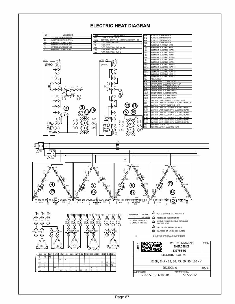
Page 87
ELECTRIC HEAT DIAGRAM
11
58
17
13
6
316
103
4
16
13
14
9
17 14
ELECTRIC HEATING
NOT USED ON 15 AND 30KW UNITS
TB3 IS USED IN SOME UNITS
KW HE1 HE2 HE3 HE4 HE5 HE6 HE7 HE10 HE11
15 7.5 7.5
30 15 15
90 15 15 15 15
F4
F3 F3 F3
HE1
S201
2
HE2
S157
1
2
HE12
HE3 OR HE13
HE14
F42 F42 F42 F43 F43 F43 F44 F44 F44
S157
3
4
S202
1
K15-1 L2
T2
K15-1
1L 1T
F3
F3
F42
F42K15-1
T3
L3
F3
F42
S157
21
HE4
HE4
HE4
REMOVE PLUG WHEN FIELD INSTALLING
ELECTRIC HEAT
TB2, CB10 OR S48 MAY BE USED
S159
1
2
S1584
3
K16-1 L2
T2
K16-1
1L 1T
F43
F43
F44
F44
K16-1
T3
L3
F43
F44
S159
4 3
HE6
HE6
HE6
S172
1
2
S1714
3
K18-1 L2
T2
K18-1
T1L1
F49
F49
F50
F50
K18-1
T3
L3
F49
F50
HE10
HE10
HE10
S172
43
K15-1
L1
T1
K15-1
L2
T2
K15-1
L3
T3 K16-1
L1
T1
K16-1
L2
T2
K16-1
L3
T3
K17-1
L1
T1
K17-1
L2
T2
K17-1
L3
T3
K18-1
L1
T1
K18-1
L2
T2
K18-1
L3
T3
S157
3
4
S158
1
2
S158
3
4
S159
1
2
S159
3
4
S160
1
2
S160
3
4
HE12 HE13 HE14
45
60 15
15 7.5
15
15
15
7.5
15
1515
J7J3
7
S107
S15 J7J3
7
P7
P37
P7
J7
P37
J37
K9-1
7
4
P37
J37K15
A B
K16
A B
K17A B
K18
A B
K9
A B
1
2
3
4
5
6
7
8
9
10
2
3
1COMK16W2
K15
H1
J266A
P266
J271A
P271A55
1
2
3
4
5
6
7
8
9
10
2
3
1
(24 VAC)
COM
K18W2
K17
H1
J332
P332
J272A
P272A178
HE1 ELEMENT, ELECTRIC HEAT 1
HE2 ELEMENT, ELECTRIC HEAT 2
HE3 ELEMENT, ELECTRIC HEAT 3
HE4 ELEMENT, ELECTRIC HEAT 4
HE5 ELEMENT, ELECTRIC HEAT 5
HE6 ELEMENT, ELECTRIC HEAT 6
HE7 ELEMENT, ELECTRIC HEAT 7
HE10 ELEMENT, ELECTRIC HEAT 10
7 ELECTRIC HEAT CONTROL37 ELECTRIC HEAT CONTROL
266 HEATING CONTROL STG 1271 HEATING SENSORS STG 1272 HEATING SENSORS STG 2
S15 SWITCH, LIMIT PRIMARY ELECTRIC HEAT
S20 SWITCH, LIMIT SECONDARY ELECTRIC HEAT 1,2
S107 SWITCH, PRIMARY ELECTRIC HEAT
S157 SWITCH, LIMIT SECONDARY ELECTRIC HEAT 2
S158 SWITCH, LIMIT SECONDARY ELECTRIC HEAT 3
S159 SWITCH, LIMIT SECONDARY ELECTRIC HEAT 4
S160 SWITCH, LIMIT SECONDARY ELECTRIC HEAT 5
K9,−1 RELAY, HEAT
K15,−1 CONTACTOR, ELECTRIC HEAT 1,2
K16,−1 CONTACTOR, ELECTRIC HEAT 1A,2A
K17,−1 CONTACTOR, ELECTRIC HEAT 3,4
K18,−1 CONTACTOR, ELECTRIC HEAT 5,6
J/P JACK/PLUG
HE11 ELEMENT, ELECTRIC HEAT 11
HE12 ELEMENT, ELECTRIC HEAT 12
HE13 ELEMENT, ELECTRIC HEAT 13
HE14 ELEMENT, ELECTRIC HEAT 14
S161
S203
4
1
2
3
4
4
2
3
1
DESIGNATION VOLTAGE
Y 208−230/60/3
BA
BB
K243
A B
K242
A B
K245A B
F49 FUSE, ELECTRIC HEAT 7
F50 FUSE, ELECTRIC HEAT 8
K242 CONTACTOR, ELECTRIC HEAT 1
K243 CONTACTOR, ELECTRIC HEAT 2
K245 CONTACTOR, ELECTRIC HEAT 4
K242 T1
L1
K243
T1
L1
K245 T1
L1
K243
L2
T2
K245
L2
T2
K242
3T 3L
K243
L3T3
K245
3T 3L
K242
L2
T2
H2H2
332 HEATING CONTROL STG 2
SWITCH, LIMIT SECONDARY ELECTRIC HEAT 6
S161
3
4
S1602
1
K17-1 L2
T2
K17-1
T1L1
F46
S160
K17-1
T3
L3
F45
F46
S161
43
HE9
HE9
HE9
K244 T1
L1
K244
L2
T2
K244
L3T3
F46
F46
HE8 HE9
15 15120 15 151515 15 15
C
D
ONLY USED ON 120KW D BOX UNITS5
5
A BK244
5
F45 FUSE, ELECTRIC HEAT 5
F46 FUSE, ELECTRIC HEAT 6
TB2 TERMINAL STRIP, UNIT
TB3 TERMINAL STRIP, ELECTRIC HEAT
S172S171 SWITCH, LIMIT SECONDARY ELECTRIC HEAT 7
SWITCH, LIMIT SECONDARY ELECTRIC HEAT 8
HE8 ELEMENT, ELECTRIC HEAT 8
HE9 ELEMENT, ELECTRIC HEAT 9
K244 CONTACTOR, ELECTRIC HEAT 3
KEY DESCRIPTION
A55
(24 VAC)
CONTROL BOARD, MAIN
F3 FUSE, ELECTRIC HEAT
F4 FUSE, UNIT
F42 FUSE, ELECTRIC HEAT 1 A, 2A
F43 FUSE, ELECTRIC HEAT 3
F44 FUSE, ELECTRIC HEAT 4
A178 CONTROL, COMP 3 & 4, 2ND STAGE HEAT − C3
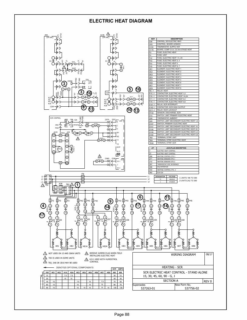
Page 88
ELECTRIC HEAT DIAGRAM
11
5
8
17
6
3
10
4
16
13
149
1
13
14
16
HEATING - SCR
NOT USED ON 15 AND 30KW UNITS
TB3 IS USED IN SOME UNITS
REMOVE JUMPER PLUG WHEN FIELD
INSTALLING ELECTRIC HEAT
TB2, S48 OR CB10 MAY BE USED
KW HE1 HE2 H1A H2A HE3 HE4 HE5 HE6 HE8
15 7.5 7.5
30 15 15
45 15 7.5 15 7.5
60 15 15 15 15
90 15 15 15 15 15 15
HE7 HE8HE3 HE4HE2AHE1A
S1571
2
HE1 HE2
S201
2
HE5 HE6
K15-1
L1
T1
J7J3
7S107
S15 J7J3
7
P7
P37
P7
J7
P37
J37
K9-1
7
4
KEY DESCRIPTION
A55 CONTROL, BOARD LENNOX
F3 FUSE, ELECTRIC HEAT
F4 FUSE, UNIT
F42 FUSE, ELECTRIC HEAT 1 A, 2A
F43 FUSE, ELECTRIC HEAT 3, 4
F44 FUSE, ELECTRIC HEAT 5
F45 FUSE, ELECTRIC HEAT 6, 7
HE1 ELEMENT, ELECTRIC HEAT 1
HE3 ELEMENT, ELECTRIC HEAT 3
HE4 ELEMENT, ELECTRIC HEAT 4
HE5 ELEMENT, ELECTRIC HEAT 5
HE6 ELEMENT, ELECTRIC HEAT 6
HE7 ELEMENT, ELECTRIC HEAT 7
HE8 ELEMENT, ELECTRIC HEAT 8
7 ELECTRIC HEAT CONTROL
37 ELECTRIC HEAT CONTROL
266 HEATING CONTROL STG 1
271 HEATING SENSORS STG 1
272 HEATING SENSORS STG 2
S15 SWITCH, LIMIT PRIMARY ELECTRIC HEAT
S20 SWITCH, LIMIT SECONDARY ELECTRIC HEAT 1,2
S107 SWITCH, PRIMARY ELECTRIC HEAT
S157 SWITCH, LIMIT SECONDARY ELECTRIC HEAT 1A
S158 SWITCH, LIMIT SECONDARY ELECTRIC HEAT 2A
S159 SWITCH, LIMIT SECONDARY ELECTRIC HEAT 3,4
S160 SWITCH, LIMIT SECONDARY ELECTRIC HEAT 5,6
TB2 TERMINAL STRIP, UNIT
TB3 TERMINAL STRIP, ELECTRIC HEATP37
J37
DESIGNATION VOLTAGE
G 460/60/3
J 575/60/3
F3 F3 F3 F42 F42 F42 F43 F43 F43 F44 F44 F44 F45 F45 F45
K15
A B
K16
A B
K17
A B
K18
A B
K9
A B
S203
4
S201
2
S203
4
S1573
4
S1581
2
S1583
4
S1591
2
S1593
4
S1601
2
S1603
4
L2
T2
L3
T3
K15-1
L1
T1
L2
T2
L3
T3 K16-1
L1
T1
L2
T2
L3
T3
K17-1
L1
T1
L2
T2
L3
T3
K18-1
L1
T1
L2
T2
L3
T3
480 600
75
90
SCR AMPS
40
30
50
75
40
15
TB2A38 TB3
K162-1
7
2
P297J297A
B
W2
A55
24
2
3
4
6
CM
A38
4
5
6
3
A104TB36
26
27
28
RT20
TSTAT
SCR CONTROL
W1
P298J298D
DO 1
C
DO 2
A55
K211-1
7 2
TB36
30STG1
S26
K161-1
7 2
A B
K162
B A
K161
B A
K211
K9,−1 RELAY, HEAT
K15,−1 CONTACTOR, ELECTRIC HEAT 1,2
K16,−1 CONTACTOR, ELECTRIC HEAT 1A,2A
K17,−1 CONTACTOR, ELECTRIC HEAT 3,4
K18,−1 CONTACTOR, ELECTRIC HEAT 5,6
1
2
3
4
5
6
7
8
9
10
2
3
1COM
K16
W2
K15
H1
(24 VAC)
J266A
P266
J271A
P271A55
1
2
3
4
5
6
7
8
9
10
2
3
1COM
K18
W2
K17
H1
(24 VAC)
J332
P332
J272A
P272A178
24VAC24
C
S26
S26 THERMOSTAT, AMBIENT
A38 CONTROL, SCR ELECTRIC HEAT
RT20 SENSOR, DISCHARGE, SCR
A104 THERMOSTAT, SUPPLY AIR
K211−1 RELAY, HEAT LOCKOUT
K162−1 CONTACTOR, SCR HIGH OUTPUT
K161−1 RELAY, SCR INTERRUPT
J/P JACK/PLUG DESCRIPTION
297 THERMOSTAT DDC INTERFACE
298 IAQ INTERFACE
A178 BOARD, COMP 3 & 4, C3 2nd STAGE HEAT
TB36 TERMINAL STRIP, SCR
1
2
4
3
32
5
5
4
1
K211 USED WITH HUMIDITROL
CONTROL5
F4
B
332 HEATING CONTROL STG. 2
HE2 ELEMENT, ELECTRIC HEAT 2
HE7
BA
B
135 135
C
D
H2
H2
1
2
J362
P362
3J362
P362
362 SCR-S26
NO C
3
17
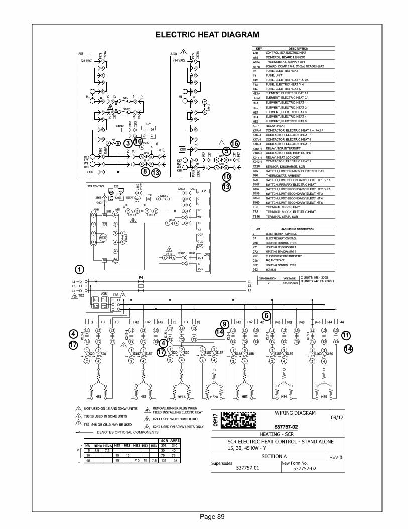
Page 89
ELECTRIC HEAT DIAGRAM
11
5
8
17
6
3
10
4
16
13
14
9
1
13
14
16
17
4
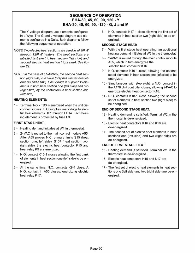
Page 90
SEQUENCE OF OPERATIONEHA-30, 45, 60, 90, 120 - Y
EHA-30, 45, 60, 90, -120 - G, J and M
The Y voltage diagram use elements configured
in a Wye. The G and J voltage diagram use ele
ments configured in a Delta. Both diagrams follow
the following sequence of operation:
NOTE:Two electric heat sections are used in all 30kW
through 120kW heaters. The heat sections are
labelled first electric heat section (left side) and
second electric heat section (right side). See fig
ure 29.
NOTE: In the case of EHA30kW, the second heat sec
tion (right side) is a slave (only has electric heat el
ements and a limit). Line voltage is supplied to ele
ments in both heat section one (left side) and two
(right side) by the contactors in heat section one
(left side).
HEATING ELEMENTS:
1 - Terminal block TB3 is energized when the unit dis
connect closes. TB3 supplies line voltage to elec
tric heat elements HE1 through HE14. Each heat
ing element is protected by fuse F3.
FIRST STAGE HEAT:
2 - Heating demand initiates at W1 in thermostat.
3 - 24VAC is routed to the main control module A55.
After A55 proves N.C. primary limits S15 (heat
section one, left side), S107 (heat section two,
right side), the electric heat contactor K15 and
heat relay K9 are energized.
4 - N.O. contact K15‐1 closes allowing the first bank
of elements in heat section one (left side) to be en
ergized.
5 - At the same time, N.O. contacts K9‐1 close. A
N.O. contact in A55 closes, energizing electric
heat relay K17.
6 - N.O. contacts K17‐1 close allowing the first set of
elements in heat section two (right side) to be en
ergized.
SECOND STAGE HEAT:
7 - With the first stage heat operating, an additional
heating demand initiates at W2 in the thermostat.
8 - 24VAC is routed through the main control module
A55, which in turn energizes the
electric heat contactor K16.
9 - N.O. contacts K16‐1 close allowing the second
set of elements in heat section one (left side) to be
energized.
10 - Simultaneous with step eight, a N.O. contact in
the A178 Unit controller closes, allowing 24VAC to
energize electric heat contactor K18.
11 - N.O. contacts K18‐1 close allowing the second
set of elements in heat section two (right side) to
be energized.
END OF SECOND STAGE HEAT:
12 - Heating demand is satisfied. Terminal W2 in the
thermostat is de‐energized.
13 - Electric heat contactors K16 and K18 are
de‐energized.
14 - The second set of electric heat elements in heat
sections one (left side) and two (right side) are
de‐energized.
END OF FIRST STAGE HEAT:
15 - Heating demand is satisfied. Terminal W1 in the
thermostat is de‐energized.
16 - Electric heat contactors K15 and K17 are
de‐energized.
17 - The first set of electric heat elements in heat sec
tions one (left side) and two (right side) are de‐en
ergized.
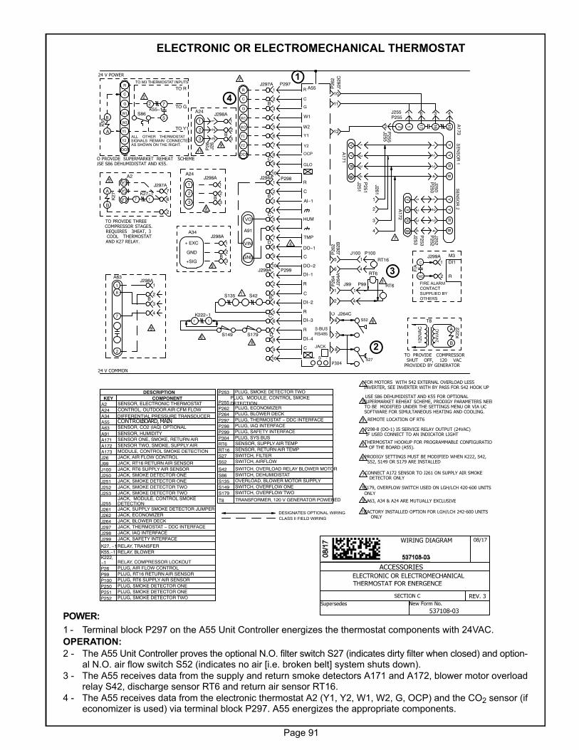
Page 91
ELECTRONIC OR ELECTROMECHANICAL THERMOSTAT
POWER:
1 - Terminal block P297 on the A55 Unit Controller energizes the thermostat components with 24VAC.
OPERATION:
2 - The A55 Unit Controller proves the optional N.O. filter switch S27 (indicates dirty filter when closed) and optional N.O. air flow switch S52 (indicates no air [i.e. broken belt] system shuts down).
3 - The A55 receives data from the supply and return smoke detectors A171 and A172, blower motor overloadrelay S42, discharge sensor RT6 and return air sensor RT16.
4 - The A55 receives data from the electronic thermostat A2 (Y1, Y2, W1, W2, G, OCP) and the CO2 sensor (ifeconomizer is used) via terminal block P297. A55 energizes the appropriate components.
ACCESSORIES
REV. 3
F/A
1
3
P298-8 (DO-1) IS SERVICE RELAY OUTPUT (24VAC)IF USED CONNECT TO AN INDICATOR LIGHT
FOR MOTORS WITH S42 EXTERNAL OVERLOAD LESSINVERTER, SEE INVERTER WITH BY PASS FOR S42 HOOK UP
REMOTE LOCATION OF RT6
DESCRIPTIONKEY COMPONENT
A2 SENSOR, ELECTRONIC THERMOSTATA24 CONTROL, OUTDOOR AIR CFM FLOWA34 DIFFERENTIAL PRESSURE TRANSDUCERA55A63 SENSOR, CO2 (IAQ) OPTIONAL
A91 SENSOR, HUMIDITYA171 SENSOR ONE, SMOKE, RETURN AIRA172 SENSOR TWO, SMOKE, SUPPLY AIRA173 MODULE, CONTROL SMOKE DETECTION
J99 JACK, RT16 RETURN AIR SENSORJ100 JACK, RT6 SUPPLY AIR SENSORJ250 JACK, SMOKE DETECTOR ONEJ251 JACK, SMOKE DETECTOR ONEJ252 JACK, SMOKE DETECTOR TWOJ253 JACK, SMOKE DETECTOR TWO
J255JACK, MODULE, CONTROL SMOKEDETECTION
J261 JACK, SUPPLY SMOKE DETECTOR JUMPERJ262 JACK, ECONOMIZERJ264 JACK, BLOWER DECKJ297 JACK, THERMOSTAT − DDC INTERFACEJ298 JACK, IAQ INTERFACEJ299 JACK, SAFETY INTERFACE
K27, −1RELAY, TRANSFERK55,−1 RELAY, BLOWERK222,−1 RELAY, COMPRESSOR LOCKOUT
P99 PLUG, RT16 RETURN AIR SENSORP100 PLUG, RT6 SUPPLY AIR SENSORP250 PLUG, SMOKE DETECTOR ONEP251 PLUG, SMOKE DETECTOR ONEP252 PLUG, SMOKE DETECTOR TWO
P253 PLUG, SMOKE DETECTOR TWO
P255PLUG, MODULE, CONTROL SMOKEDETECTION
P262 PLUG, ECONOMIZERP264 PLUG, BLOWER DECKP297 PLUG, THERMOSTAT − DDC INTERFACEP298 PLUG, IAQ INTERFACEP299 PLUG, SAFETY INTERFACEP304 PLUG, SYS BUSRT6 SENSOR, SUPPLY AIR TEMPRT16 SENSOR, RETURN AIR TEMPS27 SWITCH, FILTERS52 SWITCH, AIRFLOW
S42 SWITCH, OVERLOAD RELAY BLOWER MOTORS86 SWITCH, DEHUMIDISTAT
S149 SWITCH, OVERFLOW ONES179 SWITCH, OVERFLOW TWO
T8 TRANSFORMER, 120 V GENERATOR POWERED
CONTROL BOARD, MAIN
K27
A
B
A2
Y1
Y2
Y3
K27−117
TO PROVIDE THREECOMPRESSOR STAGES.REQUIRES 3HEAT, 3COOL THERMOSTATAND K27 RELAY.
K55
B
A
K55−17
5
2
S86
J264
A
1
2
J262
B
5
6RT6
RT6
RT16
3
A172
J253
A173P
255
P255
J250J252
P250
P252
P253
J255 1 6 3 4
J255
2
S421
J262
C
10
11
12
P297
P298J298A1
2B
3
4C
5
6
7
P299
D8
9
10J299A
1
2
3B
4
5C
6
7
10
J1001
4
P100
J991
4
P99
D8
9
J297A1
2B
3
4
5
6
7
8C
9
10
A91
VO
VIN
GND J299A1
2
J297A7
6
2
R
OCP
C
G
W1
W2
Y1
Y2
24 V COMMON
24 V POWER
4
4
S52
S27
J264C6
7
8
USE S86 DEHUMIDISTAT AND K55 FOR OPTIONALSUPERMARKET REHEAT SCHEME, PRODIGY PARAMETERS NEEDTO BE MODIFIED UNDER THE SETTINGS MENU OR VIA UCSOFTWARE FOR SIMULTANEOUS HEATING AND COOLING.
2
THERMOSTAT HOOKUP FOR PROGRAMMABLE CONFIGURATIOOF THE BOARD (A55).
5
5
6
W1
W2
P26
2P
262
P26
4C
R
C
AI−1
HUM
TMP
DO−1
C
DO−2
DI−1
R
C
DI−2
R
DI−3
R
DI−4
C
A55
P304
PRODIGY SETTINGS MUST BE MODIFIED WHEN K222, S42,S52, S149 OR S179 ARE INSTALLED
A171
J251P
251
J2611
2
3
4
7
CONNECT A172 SENSOR TO J261 ON SUPPLY AIR SMOKEDETECTOR ONLY
7
R
OCP
C
G
W1
W2
Y1
Y2
TO R
TO G
TO Y1
O PROVIDE SUPERMARKET REHEAT SCHEMEUSE S86 DEHUMIDISTAT AND K55.
ALL OTHER THERMOSTATSIGNALS REMAIN CONNECTEDAS SHOWN ON THE RIGHT.
TO M3 THERMOSTAT INPUTS2
2
DI1
R
M3
K222−1T8
120V
AC
K22
2A
B
TO PROVIDE COMPRESSORSHUT OFF, 120 VAC
PROVIDED BY GENERATOR
S1496 S179
8
8S179, OVERFLOW SWITCH USED ON LGH/LCH 420-600 UNITS
ONLY
1+ EXC
GND
+SIG
A34
2
3
J298A
B
1
2
3
J298A
B
1
2
3
A24
9
9
A63J298A
1
2B
3
4
9
9 A63, A34 & A24 ARE MUTUALLY EXCLUSIVE
1
2
3
J298A
B
1
2
3
A24
9
6
J26
3P
262
1
10FACTORY INSTALLED OPTION FOR LGH/LCH 242-600 UNITSONLY
10
P26 PLUG, AIR FLOW CONTROL
J26 JACK, AIR FLOW CONTROL
S135 OVERLOAD, BLOWER MOTOR SUPPLY
S135
3
1
4
2
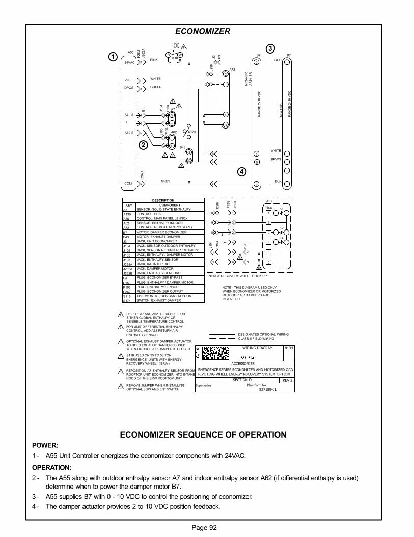
Page 92
ECONOMIZER
ECONOMIZER SEQUENCE OF OPERATION
POWER:
1 - A55 Unit Controller energizes the economizer components with 24VAC.
OPERATION:
2 - The A55 along with outdoor enthalpy sensor A7 and indoor enthalpy sensor A62 (if differential enthalpy is used)
determine when to power the damper motor B7.
3 - A55 supplies B7 with 0 - 10 VDC to control the positioning of economizer.
4 - The damper actuator provides 2 to 10 VDC position feedback.
31
4
2
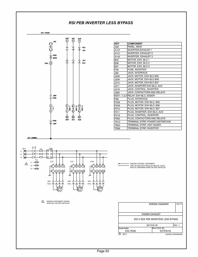
Page 93
RSI PEB INVERTER LESS BYPASS
Lennox Commercial
POWER EXHAUST
REV 1
1
R S T
WVU
GN
D
R S T
WVU
GN
D
R S T
WVU
GN
D
K20
7A
B
LINE VOLTAGE FIELD INSTALLED NEC/CEC CLASS I
DENOTES OPTIONAL COMPONENTS
NOTE-ALL REMAINING WIRES FACTORY INSTALLED
1 SEPARATE DISCONNECT WIRING
WHEN NOT FACTORY INSTALLED
KEY COMPONENTA55 PANEL, MAIN
A137 INVERTER,EXHAUST 1
A141 INVERTER, EXHAUST 2
A142 INVERTER, EXHAUST 3
B35 MOTOR, EXH, BLO 1
B36 MOTOR, EXH, BLO 2
B37 MOTOR, EXH, BLO 3
F36 FUSE, INVERTER
J69 JACK, INTERFACE
J208 JACK, MOTOR, EXH BLO B35
J209 JACK, MOTOR, EXH BLO B36
J210 JACK, MOTOR, EXH BLO B37
J211 JACK, INVERTER EXH BLO, AUX
J218 JACK, CONTROL, INVERTER
J265 JACK, CONTACTORS AND RELAYSK207,−1,2,3 RELAY, EXH BLO, ADDER
P69 PLUG, INTERFACE
P208 PLUG, MOTOR, EXH BLO, B35
P209 PLUG, MOTOR, EXH BLO, B36
P210 PLUG, MOTOR, EXH BLO, B37
P211 PLUG, INVERTER, EXH BLO, AUX
P218 PLUG, CONTROL, INVERTER
P265 PLUG, CONTACTORS AND RELAYS
TB13 TERMINAL STRIP, POWER DISTRIBTION
TB24 TERMINAL STRIP, UNIT ADDER
TB58 TERMINAL STRIP, INVERTER
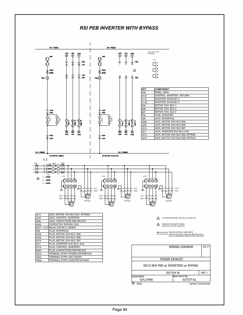
Page 94
RSI PEB INVERTER WITH BYPASS
2
R S T
WVU
GN
D
R S T
WVU
GN
D
R S T
WVU
GN
D
K20
7A
B
K20
5A
B
K20
7A
B
K20
5A
B
A137, A141, A142INVERTER
1
2
LINE VOLTAGE FIELD INSTALLED NEC/CEC CLASS I
DENOTES OPTIONAL COMPONENTS
SEPARATE DISCONNECT WIRING
WHEN NOT FACTORY INSTALLED
NOTE-ALL REMAINING WIRES FACTORY INSTALLED
KEY COMPONENTA55 PANEL, MAIN
A137 CONTROL, INVERTER, RETURN
A141 INVERTER, EXHAUST 2
A142 INVERTER, EXHAUST 3
B35 MOTOR, EXH, BLO 1
B36 MOTOR, EXH, BLO 2
B37 MOTOR, EXH, BLO 3
F36 FUSE, INVERTER
J69 JACK, INTERFACE
J208 JACK, MOTOR, EXH BLO B35
J209 JACK, MOTOR, EXH BLO B36
J210 JACK, MOTOR, EXH BLO B37
J211 JACK, INVERTER EXH BLO, AUX
J212 JACK, MOTOR, EXH BLO B35, BYPASS
J213 JACK, MOTOR, EXH BLO B36, BYPASS
J214 JACK, MOTOR, EXH BLO B37, BYPASS
J218 JACK, CONTROL, INVERTER
J265 JACK, CONTACTORS AND RELAYS
K205 CONTACTOR, BYPASS, EXH.
K207,−1,2,3 RELAY, EXH BLO, ADDER
P69 PLUG, INTERFACE
P208 PLUG, MOTOR, EXH BLO, B35
P209 PLUG, MOTOR, EXH BLO, B36
P210 PLUG, MOTOR, EXH BLO, B37
P211 PLUG, INVERTER, EXH BLO, AUX
P218 PLUG, CONTROL, INVERTER
P265 PLUG, CONTACTORS AND RELAYS
TB13 TERMINAL STRIP, POWER DISTRIBTION
TB24 TERMINAL STRIP, UNIT ADDER
TB58 TERMINAL STRIP, INVERTER BYPASS
J211
1 TO BYPASS INVERTERS, UNPLUG J211 FROM P211
Lennox Commercial
RSI D BOX PEB w/ INVERTERS w/ BYPASS
POWER EXHAUST
REV 1


![dl.mitsubishielectric.co.jp · 2019-11-07 · 1/1 lb- lb-odf6 lf-ûx2 lb-okx5 lp-a lpb-c]kx5 lb-obf7 lgh-nÛrs2 lgh-nÜrs2dÜ* lgh-nûrs3 lgh-nûrs3d lgh-nc]rx 500—5000 atž250,](https://img.pdfslide.net/doc/110x75/5e51f7fccbd97e57577c924b/dl-2019-11-07-11-lb-lb-odf6-lf-x2-lb-okx5-lp-a-lpb-ckx5-lb-obf7-lgh-nrs2.jpg)