Embed Size (px)
Citation preview
07-01802H F412-230V EU F412-110V UK 1 Legend Brands Holdings, Inc.
Owner’s Manual LGR 7000XLi Dehumidifier
Original Instructions
Models F412-230V EU & F412-110V UK LEGEND BRANDS HOLDINGS LTD.
22 Plover Close, Interchange Park, Newport Pagnell, MK16 9PS Tel: +44 (0)1908-611-211 Fax: +44 (0)1908-611-363 www.legendbrandseurope.com
Dri-Eaz® dehumidifiers reduce humidity in enclosed environments by removing water vapor
from the air. This unit is rugged, durable and highly portable, making it ideal for water damage
restoration, structural drying, construction, and other applications requiring temporary, high-
performance dehumidification.
Patents: http://www.LBpatents.com
R E A D T H E S E I N S T R U C T I O N S
SAFETY INSTRUCTIONS
WARNING! Do not alter or modify your dehumidifier
in any way. Use only replacement parts authorized
by Dri-Eaz Products, Inc. Modifications or use of
unapproved parts could create a hazard and will
void your warranty. Contact your authorized
distributor for assistance.
WARNING! Electric shock hazard, rotating fan
hazard and hot surface hazards.
Inspect the power cord before use. If cord is
damaged, do not use. Always grasp the plug (not
the cord) to unplug.
Must be earthed. Insert three-prong plug on power
cord into a matching electrically earthed outlet. Do
not use adapter. Never cut off third prong. Do not
use an extension cord.
The unit must be operated on a 230V or 110V outlet
(as appropriate) circuit protected by a Residual
Current Device device.
Keep motor and wiring dry.
Always unplug unit before cleaning or servicing.
Do not attempt to repair the unit. For service, contact
your local distributor.
FIRE HAZARD
Keep away from open flames and heat sources.
Do not use or store where vapors from gasoline,
solvents, thinners or other flammable materials may
be present.
BEFORE YOU BEGIN
Warranty registration
Warranty registration procedures vary by
country/market. Contact your local distributor for
assistance. Registration allows us to better assist you
with using, maintaining or servicing your equipment and
to contact you in case we have important safety
information concerning your Dri-Eaz product. If you
determine service is required, have your equipment
model, serial number and original proof of purchase
available and ask for assistance with obtaining a return
material authorization (RMA).
GROUNDING INSTRUCTIONS
This unit’s plug must be inserted into an appropriate outlet that is properly installed and grounded in accordance with all local codes and ordinances.
WARNING! Improper connection of the equipment-grounding conductor can result in a risk of electric shock. Check with a qualified electrician or service person if you are in doubt as to whether the outlets are properly grounded. Do not modify the plugs provided with the appliance – if the plugs do not fit the outlets, have proper outlets installed by a qualified electrician.
This equipment is for use on circuits with a nominal rating of no more than 230V or 110V (as appropriate).
Handle the unit carefully
Always operate the unit on a stable, level surface. Do
not drop, throw, or place where it could fall. Rough
treatment can damage the unit, and may create a
hazardous condition or void the warranty.
This unit intended for household and commercial use.
WARNING
07-01802H F412-230V EU F412-110V UK 2 Legend Brands Holdings, Inc.
CONTROLS AND OPERATING INSTRUCTIONS
Set unit upright NOTICE: Always store, transport, and use the unit in a horizontal position. If the unit is ever placed in a vertical position, return it to the horizontal position and let it stand for at least 30 minutes before turning it on.
Positioning a Dehumidifier
For best results, operate your dehumidifiers in an
enclosed area. Close all doors and windows that open to
the outside to maximize water removal efficiency. Place
your dehumidifier away from obstructions, and keep it
away from anything that could block airflow into and out
of the unit. For more information about creating an
optimum drying environment, contact your local
distributor.
Set up drain hose
The condensate pump connects to a plastic drainage
hose. This hose is equipped with a quick-connect fitting
for quick attachment to the provided 12 m drain hose.
Unwrap the entire hose and place the unattached end in
a sink, drain, bucket or outdoors – anywhere that water
can drain out safely. If you use a bucket or other
container for water collection, check it regularly to
prevent overflows.
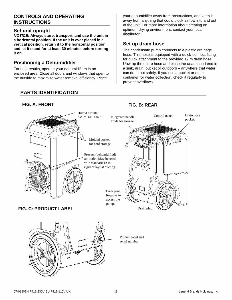
Product label and
serial number.
FIG. A: FRONT FIG. B: REAR
Humid air inlet.
3M™ HAF filter.
Molded pocket
for cord storage.
Process (dehumidified)
air outlet. May be used
with standard 12 in.
rigid or layflat ducting.
FIG. C: PRODUCT LABEL
Back panel.
Remove to
access the
pump.
Integrated handle.
Folds for storage.
Drain hose
pocket. Control panel.
PARTS IDENTIFICATION
Drain plug
07-01802H F412-230V EU F412-110V UK 3 Legend Brands Holdings, Inc.
NOTICE: Uncoil and straighten the entire drain hose. Do
not leave any part of the hose coiled and do not place
the end of the hose higher than 6 m above the bottom of
the unit. Also check for kinks or other obstructions that
might restrict the flow of water. Obstructions may cause
a water backup and result in overflows.
Plug in electrical cord
The 110V UK unit should be plugged into a 5kVA
transformer box. The 230V unit should be plugged into
an appropriate outlet.
Startup display and normal display modes
When unit is first plugged in to AC power, the control
panel display will briefly cycle through a series of
readouts. This is part of the unit’s self-diagnosis
procedure and no user intervention is required.
Startup display and normal display modes
When unit is first plugged in to AC power, the control
panel display will briefly cycle through a series of
readouts. This is part of the unit’s self-diagnosis
procedure and no user intervention is required.
Once the self-diagnosis is complete, the display will
switch to normal display mode.
Turn the unit on
The control panel has a display and a touchpad with four
keys. Press the ON/OFF to turn the unit on. The unit
will now go through a compressor delay countdown (up
to sixty seconds in duration) and a self diagnostics
process.
Once the compressor delay countdown and self-
diagnostics are complete, the display will switch to
normal display mode.
UNIT ON 00 HRS
INLET 00°C / INLET 00%
The first line of the display shows the total number of
hours the unit has been in operation. This value may be
reset to zero to track job hours (see “Job Hours Reset”
below). The second line of the display alternates
between inlet temperature and inlet humidity.
User Settings Menu
A number of display settings may be changed by the
user. System information can also be displayed. These
items are accessed by pressing DISPLAY MENU.
Each press of the key will display the next parameter.
When you reach the parameter you wish to adjust, press
MENU SELECTION to increase the value. Press
DISPLAY MENU again to accept the setting and re-start
the display cycle.
Note that only menu items followed by a greater-than symbol ( > ) may be adjusted.
Error messages
If the onboard diagnostics discover a problem, the unit will display an error message. See “Error Messages,” p. 9, for an explanation of each message.
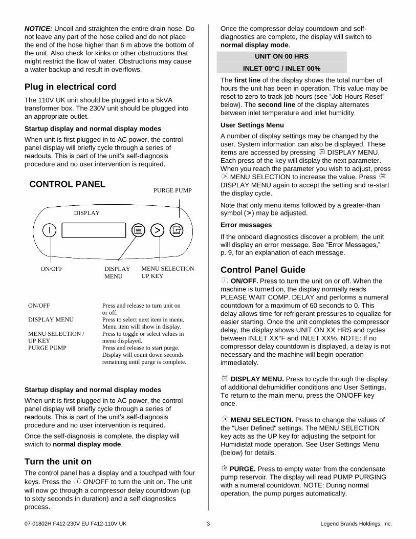
Control Panel Guide
ON/OFF. Press to turn the unit on or off. When the
machine is turned on, the display normally reads
PLEASE WAIT COMP. DELAY and performs a numeral
countdown for a maximum of 60 seconds to 0. This
delay allows time for refrigerant pressures to equalize for
easier starting. Once the unit completes the compressor
delay, the display shows UNIT ON XX HRS and cycles
between INLET XX°F and INLET XX%. NOTE: If no
compressor delay countdown is displayed, a delay is not
necessary and the machine will begin operation
immediately.
DISPLAY MENU. Press to cycle through the display
of additional dehumidifier conditions and User Settings.
To return to the main menu, press the ON/OFF key
once.
MENU SELECTION. Press to change the values of
the "User Defined" settings. The MENU SELECTION
key acts as the UP key for adjusting the setpoint for
Humidistat mode operation. See User Settings Menu
(below) for details.
PURGE. Press to empty water from the condensate
pump reservoir. The display will read PUMP PURGING
with a numeral countdown. NOTE: During normal
operation, the pump purges automatically.
ON/OFF Press and release to turn unit on
or off.
DISPLAY MENU Press to select next item in menu.
Menu item will show in display.
MENU SELECTION /
UP KEY
Press to toggle or select values in
menu displayed.
PURGE PUMP Press and release to start purge.
Display will count down seconds
remaining until purge is complete.
CONTROL PANEL
ON/OFF
DISPLAY
DISPLAY
MENU
MENU SELECTION /
UP KEY
PURGE PUMP
07-01802H F412-230V EU F412-110V UK 4 Legend Brands Holdings, Inc.
Changing settings and viewing system information
Display setting changes and system information can be
accessed by pressing DISPLAY MENU. Each press
of the key will display the next parameter (see list
below). When you reach the parameter you wish to
adjust, press MENU SELECTION to increase the
value. Press DISPLAY MENU again to accept the
setting and re-start the display cycle Note that only menu items followed by a greater-than symbol ( > ) may be adjusted.
07-01802H F412-230V EU F412-110V UK 5 Legend Brands Holdings, Inc.
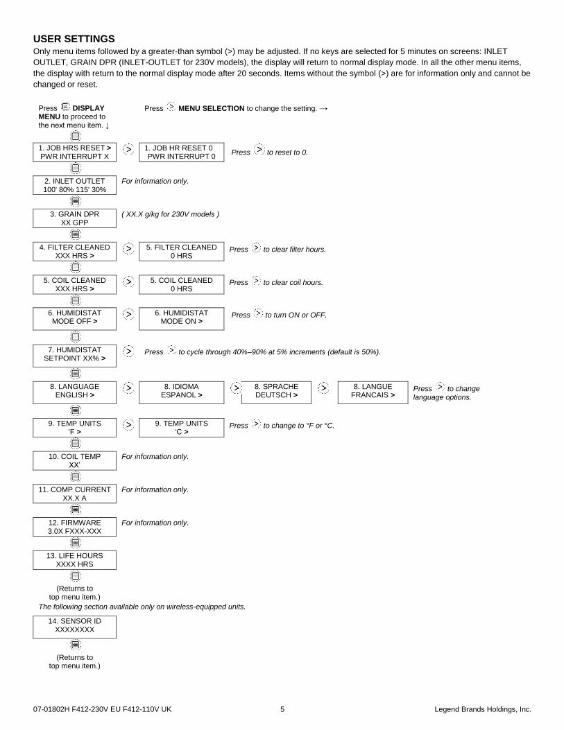
USER SETTINGS Only menu items followed by a greater-than symbol (>) may be adjusted. If no keys are selected for 5 minutes on screens: INLET
OUTLET, GRAIN DPR (INLET-OUTLET for 230V models), the display will return to normal display mode. In all the other menu items,
the display with return to the normal display mode after 20 seconds. Items without the symbol (>) are for information only and cannot be
changed or reset.
Press DISPLAY MENU to proceed to the next menu item. ↓
Press MENU SELECTION to change the setting. →
1. JOB HRS RESET > PWR INTERRUPT X
1. JOB HR RESET 0 PWR INTERRUPT 0
Press to reset to 0.
2. INLET OUTLET 100' 80% 115' 30%
For information only.
3. GRAIN DPR XX GPP
( XX.X g/kg for 230V models )
4. FILTER CLEANED XXX HRS >
5. FILTER CLEANED
0 HRS Press to clear filter hours.
5. COIL CLEANED XXX HRS >
5. COIL CLEANED
0 HRS Press to clear coil hours.
6. HUMIDISTAT MODE OFF >
6. HUMIDISTAT
MODE ON > Press to turn ON or OFF.
7. HUMIDISTAT SETPOINT XX% >
Press to cycle through 40%–90% at 5% increments (default is 50%).
8. LANGUAGE ENGLISH >
8. IDIOMA
ESPANOL >
8. SPRACHE DEUTSCH >
8. LANGUE
FRANCAIS > Press to change language options.
9. TEMP UNITS 'F >
9. TEMP UNITS
‘C > Press to change to °F or °C.
10. COIL TEMP XX’
For information only.
11. COMP CURRENT XX.X A
For information only.
12. FIRMWARE 3.0X FXXX-XXX
For information only.
13. LIFE HOURS XXXX HRS
(Returns to top menu item.)
The following section available only on wireless-equipped units.
14. SENSOR ID XXXXXXXX
(Returns to top menu item.)
07-01802H F412-230V EU F412-110V UK 6 Legend Brands Holdings, Inc.
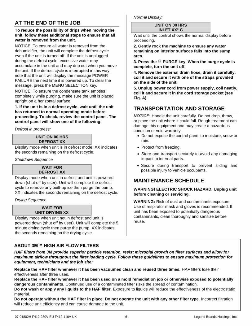
AT THE END OF THE JOB
To reduce the possibility of drips when moving the
unit, follow these additional steps to ensure that all
water is removed from the unit.
NOTICE: To ensure all water is removed from the
dehumidifier, the unit will complete the defrost cycle
even if the unit is turned off. If the unit is unplugged
during the defrost cycle, excessive water may
accumulate in the unit and may drip out when you move
the unit. If the defrost cycle is interrupted in this way,
note that the unit will display the message POWER
FAILURE the next time it is powered up. To clear the
message, press the MENU SELECTION key.
NOTICE: To ensure the condensate tank empties
completely while purging, make sure the unit is placed
upright on a horizontal surface.
1. If the unit is in a defrost cycle, wait until the unit
has returned to normal operating mode before
proceeding. To check, review the control panel. The
control panel will show one of the following:
Defrost in progress:
UNIT ON 00 HRS DEFROST XX
Display mode when unit is in defrost mode. XX indicates
the seconds remaining on the defrost cycle.
Shutdown Sequence
WAIT FOR DEFROST XX
Display mode when unit in defrost and unit is powered
down (shut off by user). Unit will complete the defrost
cycle to remove any built-up ice then purge the pump.
XX indicates the seconds remaining on the defrost cycle.
Drying Sequence
WAIT FOR UNIT DRYING XX
Display mode when unit not in defrost and unit is
powered down (shut off by user). Unit will complete the 5
minute drying cycle then purge the pump. XX indicates
the seconds remaining on the drying cycle.
Normal Display:
UNIT ON 00 HRS INLET XX° C
Wait until the control shows the normal display before
proceeding.
2. Gently rock the machine to ensure any water
remaining on interior surfaces falls into the sump
area.
3. Press the PURGE key. When the purge cycle is
complete, turn the unit off.
4. Remove the external drain hose, drain it carefully,
coil it and secure it with one of the straps provided
on the side of the unit.
5. Unplug power cord from power supply, coil neatly,
coil it and secure it in the cord storage pocket (see
Fig. A).
TRANSPORTATION AND STORAGE
NOTICE: Handle the unit carefully. Do not drop, throw,
or place the unit where it could fall. Rough treatment can
damage this equipment and may create a hazardous
condition or void warranty.
Do not expose the control panel to moisture, snow or
rain.
Protect from freezing.
Store and transport securely to avoid any damaging
impact to internal parts.
Secure during transport to prevent sliding and possible injury to vehicle occupants.
MAINTENANCE SCHEDULE
WARNING! ELECTRIC SHOCK HAZARD. Unplug unit
before cleaning or servicing.
WARNING: Risk of dust and contaminants exposure.
Use of respirator mask and gloves is recommended. If
unit has been exposed to potentially dangerous
contaminants, clean thoroughly and sanitize before
reuse.
ABOUT 3M™ HIGH AIR FLOW FILTERS
HAF filters from 3M provide superior particle retention, resist microbial growth on filter surfaces and allow for
maximum airflow throughout the filter loading cycle. Follow these guidelines to ensure maximum protection for
equipment, technicians and the job site:
Replace the HAF filter whenever it has been vacuumed clean and reused three times. HAF filters lose their
effectiveness after three uses.
Replace the HAF filter whenever it has been used on a mold remediation job or otherwise exposed to potentially
dangerous contaminants. Continued use of a contaminated filter risks the spread of contamination.
Do not wash or apply any liquids to the HAF filter. Exposure to liquids will reduce the effectiveness of the electrostatic
material.
Do not operate without the HAF filter in place. Do not operate the unit with any other filter type. Incorrect filtration
will reduce unit efficiency and can cause damage to the unit.
07-01802H F412-230V EU F412-110V UK 7 Legend Brands Holdings, Inc.
NOTICE: The unit is fitted with sensitive electronic
sensors. Protect the sensors and their lead wires from
damage and do not expose them to water or cleaning
solution.
Before each use
Inspect the electrical cord for damage. Look for
fraying, cuts, etc. Replace the cord if you find any
damage.
Inspect, vacuum or replace filter. The unit is provided
with a 3M™ HAF High Air Flow filter (part no. F372).
HAF filters may be vacuumed clean and reused up to
three times before replacement. Use a HEPA vacuum
and brush tool to remove any dust or debris. Do not use
compressed air or expose the filter to any liquids, as this
may damage the filter.
Monthly Inspect coils. Clean when dust accumulation is visible.
In normal use, dust can accumulate and can restrict
airflow, reducing performance and causing the unit to
overheat. Use a vacuum cleaner with a brush tool and a
soft cloth to remove any debris. Take care not to
damage any interior components.
To maintain appearance, wipe interior and exterior
surfaces with a damp cloth. For deep cleaning and a
lasting, protective shine, use an automotive interior
cleaner.
As Needed
Clean pump check valve and basin. If the unit displays
the message “ER9 PUMP BLOCKED PUMP & HOSE”,
the pump check valve and pump basin may need to be
cleaned. Remove cover. Remove screws from pump
base and lift out pump. Wipe out pump basin with a
damp cloth. Unthread barbed fitting with check valve and
rinse fitting and check valve with clean water. Reinstall
barbed fitting into pump. Do not overtighten. Reinstall
pump on base. Reinstall cover. Clean coils. With the
cover removed, inspect both coils. If excessive dust and
debris is present, vacuum thoroughly and/or clean with
coil cleaner.
For detailed maintenance instructions visit
www.legendbrandseurope.com
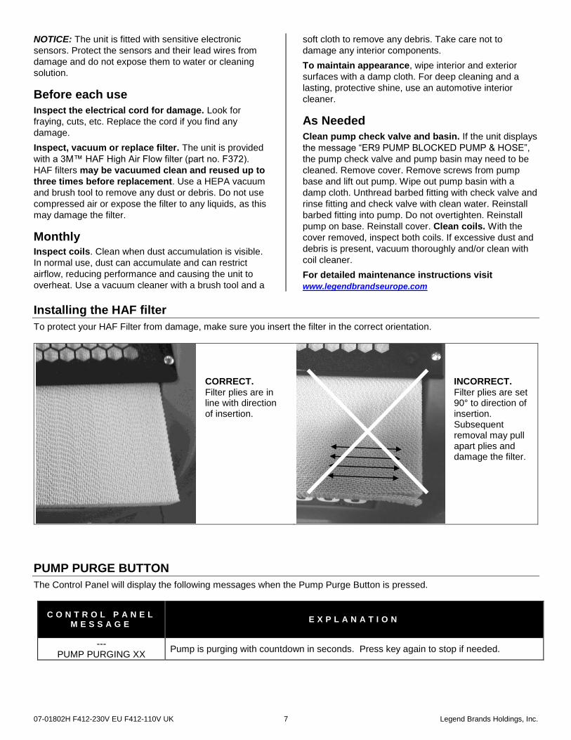
Installing the HAF filter
To protect your HAF Filter from damage, make sure you insert the filter in the correct orientation.
CORRECT. Filter plies are in line with direction of insertion.
INCORRECT. Filter plies are set 90° to direction of insertion. Subsequent removal may pull apart plies and damage the filter.
PUMP PURGE BUTTON
The Control Panel will display the following messages when the Pump Purge Button is pressed.
C O N T R O L P A N E L M E S S A G E
E X P L A N A T I O N
--- PUMP PURGING XX
Pump is purging with countdown in seconds. Press key again to stop if needed.
07-01802H F412-230V EU F412-110V UK 8 Legend Brands Holdings, Inc.
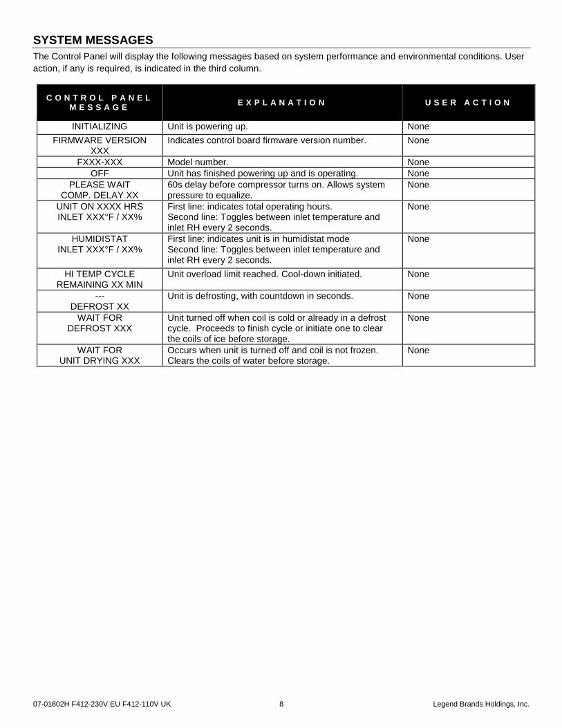
SYSTEM MESSAGES
The Control Panel will display the following messages based on system performance and environmental conditions. User
action, if any is required, is indicated in the third column.
C O N T R O L P A N E L M E S S A G E
E X P L A N A T I O N U S E R A C T I O N
INITIALIZING Unit is powering up. None
FIRMWARE VERSION XXX
Indicates control board firmware version number. None
FXXX-XXX Model number. None
OFF Unit has finished powering up and is operating. None
PLEASE WAIT COMP. DELAY XX
60s delay before compressor turns on. Allows system pressure to equalize.
None
UNIT ON XXXX HRS INLET XXX°F / XX%
First line: indicates total operating hours. Second line: Toggles between inlet temperature and inlet RH every 2 seconds.
None
HUMIDISTAT INLET XXX°F / XX%
First line: indicates unit is in humidistat mode Second line: Toggles between inlet temperature and inlet RH every 2 seconds.
None
HI TEMP CYCLE REMAINING XX MIN
Unit overload limit reached. Cool-down initiated. None
--- DEFROST XX
Unit is defrosting, with countdown in seconds. None
WAIT FOR DEFROST XXX
Unit turned off when coil is cold or already in a defrost cycle. Proceeds to finish cycle or initiate one to clear the coils of ice before storage.
None
WAIT FOR UNIT DRYING XXX
Occurs when unit is turned off and coil is not frozen. Clears the coils of water before storage.
None
07-01802H F412-230V EU F412-110V UK 9 Legend Brands Holdings, Inc.
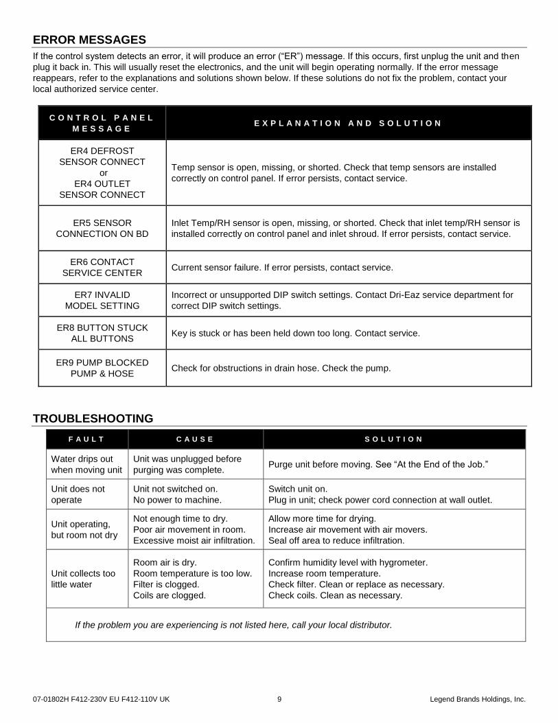
ERROR MESSAGES
If the control system detects an error, it will produce an error (“ER”) message. If this occurs, first unplug the unit and then
plug it back in. This will usually reset the electronics, and the unit will begin operating normally. If the error message
reappears, refer to the explanations and solutions shown below. If these solutions do not fix the problem, contact your
local authorized service center.
C O N T R O L P A N E L
M E S S A G E E X P L A N A T I O N A N D S O L U T I O N
ER4 DEFROST
SENSOR CONNECT
or
ER4 OUTLET
SENSOR CONNECT
Temp sensor is open, missing, or shorted. Check that temp sensors are installed
correctly on control panel. If error persists, contact service.
ER5 SENSOR
CONNECTION ON BD
Inlet Temp/RH sensor is open, missing, or shorted. Check that inlet temp/RH sensor is
installed correctly on control panel and inlet shroud. If error persists, contact service.
ER6 CONTACT
SERVICE CENTER Current sensor failure. If error persists, contact service.
ER7 INVALID
MODEL SETTING
Incorrect or unsupported DIP switch settings. Contact Dri-Eaz service department for
correct DIP switch settings.
ER8 BUTTON STUCK
ALL BUTTONS Key is stuck or has been held down too long. Contact service.
ER9 PUMP BLOCKED
PUMP & HOSE Check for obstructions in drain hose. Check the pump.
TROUBLESHOOTING
F A U L T C A U S E S O L U T I O N
Water drips out
when moving unit
Unit was unplugged before
purging was complete. Purge unit before moving. See “At the End of the Job.”
Unit does not
operate
Unit not switched on.
No power to machine.
Switch unit on.
Plug in unit; check power cord connection at wall outlet.
Unit operating,
but room not dry
Not enough time to dry.
Poor air movement in room.
Excessive moist air infiltration.
Allow more time for drying.
Increase air movement with air movers.
Seal off area to reduce infiltration.
Unit collects too
little water
Room air is dry.
Room temperature is too low.
Filter is clogged.
Coils are clogged.
Confirm humidity level with hygrometer.
Increase room temperature.
Check filter. Clean or replace as necessary.
Check coils. Clean as necessary.
If the problem you are experiencing is not listed here, call your local distributor.
07-01802H F412-230V EU F412-110V UK 10 Legend Brands Holdings, Inc.
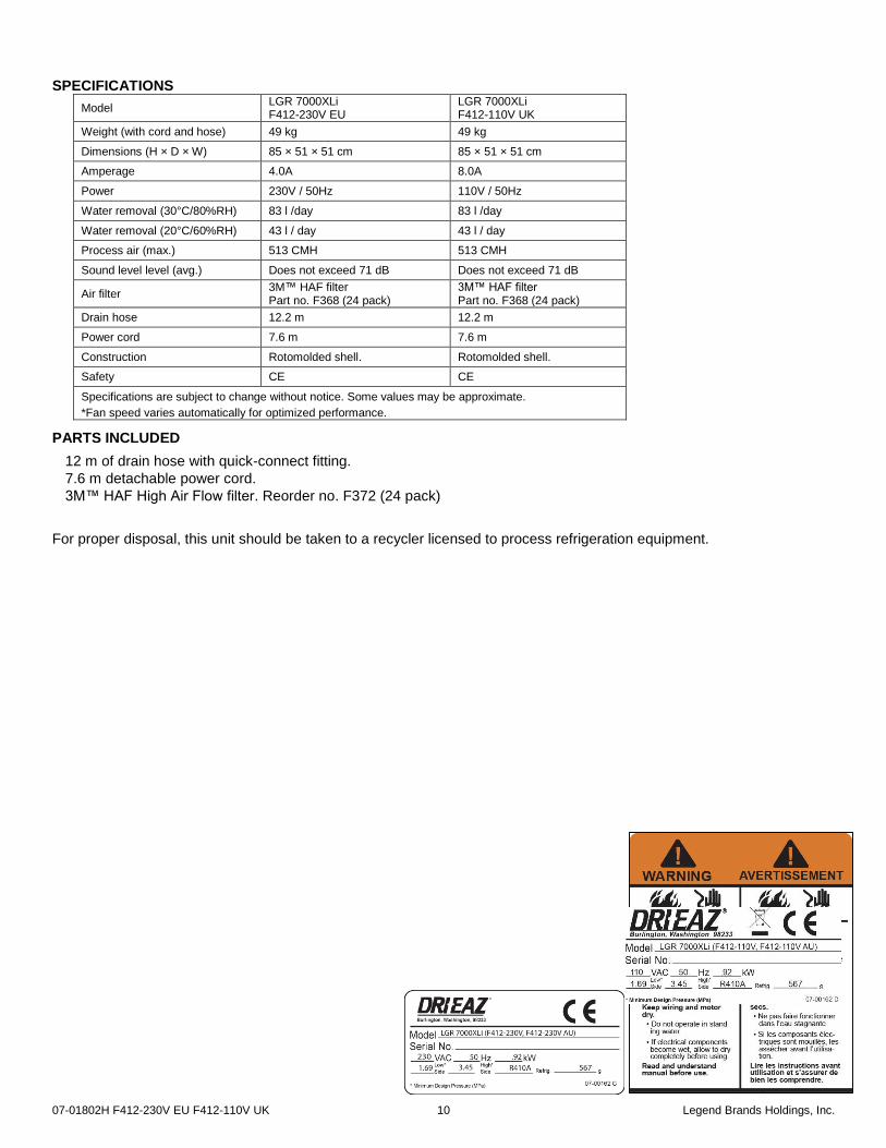
SPECIFICATIONS
Model LGR 7000XLi F412-230V EU
LGR 7000XLi F412-110V UK
Weight (with cord and hose) 49 kg 49 kg
Dimensions (H × D × W) 85 × 51 × 51 cm 85 × 51 × 51 cm
Amperage 4.0A 8.0A
Power 230V / 50Hz 110V / 50Hz
Water removal (30°C/80%RH) 83 l /day 83 l /day
Water removal (20°C/60%RH) 43 l / day 43 l / day
Process air (max.) 513 CMH 513 CMH
Sound level level (avg.) Does not exceed 71 dB Does not exceed 71 dB
Air filter 3M™ HAF filter Part no. F368 (24 pack)
3M™ HAF filter Part no. F368 (24 pack)
Drain hose 12.2 m 12.2 m
Power cord 7.6 m 7.6 m
Construction Rotomolded shell. Rotomolded shell.
Safety CE CE
Specifications are subject to change without notice. Some values may be approximate.
*Fan speed varies automatically for optimized performance.
PARTS INCLUDED
12 m of drain hose with quick-connect fitting.
7.6 m detachable power cord.
3M™ HAF High Air Flow filter. Reorder no. F372 (24 pack)
For proper disposal, this unit should be taken to a recycler licensed to process refrigeration equipment.
07-01802H F412-230V EU F412-110V UK 11 Legend Brands Holdings, Inc.
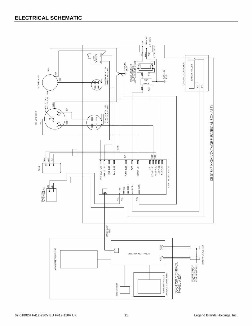
ELECTRICAL SCHEMATIC