Embed Size (px)
Citation preview

LHeC : Muon Systems
L. Pontecorvo

OutlineReview of LHC Muon Systems
Different Magnetic Field configurationsATLAS & CMS Installation and CommissioningPerformance
Review of Muon Detector TechnologiesTechnologies considered for the LHC experiments Upgrades.
Muon Physics at LHeC Possible Muon System for LHeC

3
The magnetic field choice Central solenoid with muon
measurement in the Iron used for Flux return (CMS) Compact detector Very good muon identification capability No need of very high resolution detectors High precision muon measurement rely
on the inner tracker (ITK) measurement. Pt resolution quite dependent on h
Air Core Toroid (ATLAS) Excellent Stand Alone momentum
measurement Quite uniform resolution even at large h But… Need very large detector Very not-uniform Field Map Very demanding on detectors
performances, calibration and alignment

4
The magnetic field choice
Field Integral vs h
Air Core Toroids:• Inhomogeneous Field integral in the
tracking volume• Calibration dependent from the non
bending coordinate • Precision tracking more difficult:
very accurate knowledge of B field required
Central Solenoid with Iron return Flux:• Very homogeneous in the Central
region, but high gradients in the Forwards Region.
• The Bending Power in the ITK is small in the Forward: Pt resolution is limited by MS in the Iron Yoke .

5
The ATLAS muon spectrometer
Precision Chambers: from 3 Stations Sagitta in bending plane -> measure P Monitored Drift Tubes (MDT)+ Cathode Drift Chambers (CSC) 2.0<h<2.7
Trigger Chambers: LVL1 m trigger + coordinate in non-bending plane Resistive Plate Chambers (RPC) |h|<1+Thin Gas Chamber (TGC) 2.4>|h|>1
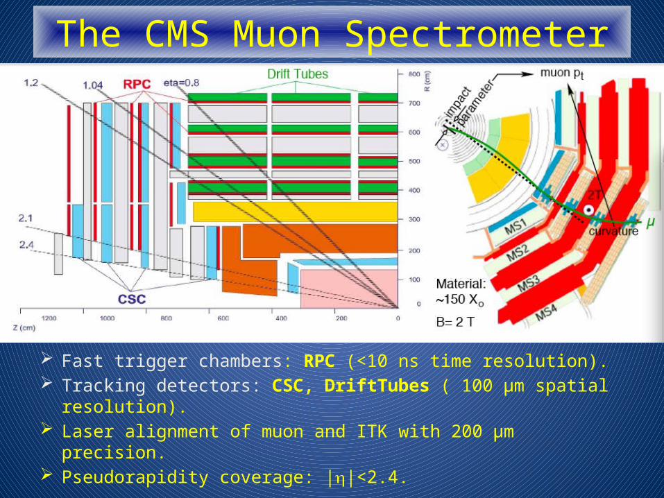
The CMS Muon Spectrometer
Fast trigger chambers: RPC (<10 ns time resolution). Tracking detectors: CSC, DriftTubes ( 100 μm spatial resolution). Laser alignment of muon and ITK with 200 μm precision. Pseudorapidity coverage: |h|<2.4.

Installation and Commissioning Installation of both ATLAS and CMS took years
Ex. The Construction of the ATLAS Muon Spectrometer started in 2005 (Barrel) and ended in 2008 (End Cap).
Very long years of commissioning with Cosmic rays were essential to be able to efficiently record and understand data from the very first collision.
This has to be considered in building the schedule for the construction and commissioning of the LHeC detector
ATLAS Barrel Resolution with Cosmic rays

Muon Reconstruction 1. Definition of regions of
activity (RoA).
2. Reconstruction of local straight segments in the RoA.
3. Combination of local segments.
4. Global fit in the muon system.
Final combination/global fit with the Inner Tracker (ITK)
- to refine the momentum measurement
- to identify low-pt muons
- to identify isolated muons and remove fakes ( ,p K decays)
Muon Definitions Segment tagged (Tag) : Pt Measured only by ITK, high efficiencyCombined (CB): Pt measured combining ITK and MS, best Momentum determination over the full range high purityStand Alone (SA): Muon measured only in the MS (High eta region in ATLAS)

Performance

Combined Pt ResolutionCombined Muons:
excellent Pt measurement up to 1 TeV (s pt)/pt<12%.
Better Combined resolution in CMS Barrel mainly due to higher B field.Better Combined End Cap Resolution in ATLAS due to Air Core Toroid

Tracking efficiency: Tag and ProbeCombined + segment
tagged muons very high and uniform
tracking efficiency
• Very high efficiency down to low transverse momenta.

Resolution Spectacular Di-muon Spectrum Well understood Z mass resolution
Resolution at High Momentum very close to design value
Limited by alignment and calibration accuracy Muon Chambers alignment in ATLAS
< 100 mm

Detector technologies: TrackingAll the detector technologies used for the present LHC
detectors can be re-used (at least in the Central-End Cap Region) in a LHeC muon system.Both CMS and ATLAS are Using Drift Tubes and CSC for
precision tracking.

Detector technologies: TrackingDrift Tube Example: ATLAS MDT.
Drift tubes mechanical parameters:Tube Radius : 15 mmTube thickness 400 mmWire diameter. 50 mmTube length: 1-6 mtChamber mech. Precision 20 mmTwo Multilayers of 3 or 4 layers each.
Operating Conditions
Gas Mixture: 93 % Ar 7% CO2
Absolute pressure: 3 Bar
HV: 3080 V
Gas Gain: 2x10⁴
Threshold: 25 electronsSingle Hit resolution

Detector technologies: Tracking MDT performance vs hit rate
Perfectly adequate for the rates foreseen in the Barrel and part of End Cap region
Not enough rate capabilities for the inner region of the End Cap at luminosities exceeding 2x1034 cm-1s-1
Using smaller diameter tubes can enhance the rate performance
Using Drift Tubes in the Central-Forward region of an LHeC muon detector should not be a problem.

Detector Technologies: Trigger Trigger chambers requirements:
Time resolution adequate to resolve the Bunch ID (few ns)
Moderate Space resolution to define Coincidence Roads (cm)
Both ATLAS and CMS use RPC (+DT, CMS) in the Barrel Region
ATLAS uses TGC (| |h <2.4) due to better rate capabilities and CMS uses RPC in the End Cap region (| |h <1.6).
New developments on RPC and TGC will improve both Spatial and Time resolution on these Detectors Possibility to use these detectors both
for triggering and tracking in the Central-Forward region of the LHeC Muon detector

Detector Technologies: TriggerRPCs: High efficiency and excellent time resolution
Operating Conditions
(Egas~ 5 KV/mm)
Gas: C2H2F4 95% - C4H10 4.5% - SF6 0.5% ;
bakelite ~ 2x1010 cm ;
Gas Gap d = 2 mm ; Graphite coated HV electrodesCu read out strips 30 mm pitchTime resolution ~2.0 ns
Bakelite Plates Foam
PET spacers
Graphite electrode
s
X readout stripsHV
Y readout strips
Grounded planes
Gas

Detector Technologies: Trigger
MWPC with small cathode-cathode distance:Anode pitch: 1.8 mmAnode-Cathode dist: 1.4 mmCathode-Cathode dist: 2.8 mm
Operating conditionsGas : 55 % CO2 , 45 % N-Pentane
HV: 3.1 KVSaturated avalanche modeVery short drift time due to the thin gap: ensures the good time resolution needed for Bunch Crossing IDWire signal used to provide the triggerStrip signals used for the second coordinate (< cm resolution)
s
l

Detectors for the Upgrade sTGC:
Small strips TGC are considered for tracking and trigger in the ATLAS New Small Wheel project.
Charge on 3 mm strips, read-out with Time over Threshold technique will ensure ~100 mm space resolution at trigger level.
Time resolution (same as for Standard TGC) adequate for BC ID.
Test Beam Result :Space Resolution< 100 mm
Test Beam Result :Angular Resolution< 0.5 mrad

Detectors for the Upgrade mRPC:
Use of new Front End electronics extends the Rate Capability in the 10 KHz/cm2 range
Time resolution improvements down to sub ns range (New electronics and smaller backelite thickness )
Space resolution using COG technique with 3 mm strips in the 100 mm range
Signal for 2 mm backelite
Signal for 1 mm backelite
Position resolution 200 mm with 3 mm strips

Detectors for the Upgrade Micromegas: Tracking (+Trigger)
Excellent Position resolution Very high granularity (excellent 2
track separation) Very good rate capability. Use of resistive strips improved
dramatically Spark behaviour Chosen for the ATLAS Phase 1
upgrade: Technology under development
500 µm strip pitch

Detectors for the UpgradeTriple GEMs: Tracking+Trigger
Good Position and time resolutionVery high granularity (excellent 2
track separation)Very good rate capability.Chosen for the CMS Phase 1
upgrade: Technology under development
0.4 mm stripss~115 mm
Stable Gain vs very large integrated charge
Ageing properties

Examples of Muon Physics at LHeC Heavy Flavour production and
Gluon PDFs Top Production
Precision measurement of Mass and Cross Section
Vector mesons: J/Psi and Y Higgs
Possibility to study Higgs coupling (e.g to bb) in a cleaner environment wrt LHC
General features: Interesting events at very small/large polar angle, high momentum muons emitted very forward. Need to further study and simulate
these physics channels to better asses the muon detector requirements

LHeC Muon Detector requirements Very large acceptance
down to 1o and 179o
Muon Identification through matching of Inner tracker track with muon Segments in the muon system.
Stand alone muon measurement in the very forward region
Muon trigger Integration in the proposed
magnet systems (Central Solenoid + 2 Dipoles)
Very mild requirements on rate capabilities compared with LHC muon detectors

Possible Muon SystemsBarrel and End Cap Region (up to 10o<q< 170o)
Region Covered by Inner Tracker AcceptanceGood momentum, impact parameter and polar angle
measurement up to ~TeV. Need Muon identification
60% @ 1 TeV
spt/pt2 vs Polar Angle sIP vs Polar Angle
<10 mm@ 1 TeV
1 GeV
10 GeV1000 GeV
Forward tracker Backward tracker

Possible Muon Systems Barrel and End Cap Region Option 1)
Muon Tagger
Trigger and tracking detectors with good time resolution and rough space resolution
mRPC or sTGC good candidates (see previous slides) OR
Drift Tubes and RPC for triggering
Matching the ID muon track with the Muon catcher segments using only position information (within a given time window)
No Pt matching.
Z mass with segment tagged m
Tagging Efficiency

Possible Muon SystemsBarrel and and End Cap
RegionOption 1 cntd)
Three stations of triggering and tracking detectors spaced by iron absorbers.
Can possibly profit from an Existing Magnet As Absorber
Iron 30-40 cm Density 7.87 g/cm3 Radiation length 1.76 cmInteraction Length 131.9
g/cm2
dE/dx 1.45 MeV/g/cm2
3 Stations3-4 layers of measuring planes per stationNo momentum selection from trigger only geometrical coincidences.Pointing to IP
~2 l ~17 X0

Possible Muon SystemsBarrel and End Cap Region
(up to10o<q< 170o)Option 2) (Ferrari Solution)
Muon Spectrometer with Stand Alone capabilitiesUse of 2 coupled Solenoid one in
the inner region (ID) and the other one in the Muon Region.
Excellent Field configuration (very uniform) 1.5 T. Coverage of bending power down to very small angles.
Precise momentum measurement from few GeV to 500 GeV.
Trigger and tracking detectors with good time resolution and excellent space resolution
Matching the ID muon track with the Muon Spectrometer track both in position and in momentum
Three stations of triggering and tracking detectors
Need sophisticated and excellent alignment system to exploit the stand alone capability.

Very Forward region Coverage up to 1o<q < 10o and 170o<
q<179o for superior acceptance of vector mesons, Top decay products, Leptoquarks etc.
Stand alone momentum measurements needed Poor performance of Inner tracker in this region
Some overlap with the Forward region needed to understand efficiencies, fakes and
resolution of Stand Alone muons.
In Forward direction high momentum muons, opening angles between muons very small Very good two tracks resolution
Highly segmented detectors Micromegas or GEMs
High momentum resolution can be achieved with air core toroids.
Vector meson Acceptance

Possible Magnetic configurations Air Core Toroid
Excellent stand alone momentum resolution
Need of excellent space resolution, segmentation and alignment on detector side
More Complex Possible interference of the
fringe field on Beam
Iron Toroid Easy and Chip No Fringe Field on Beam Limited Pt resolution due to
Multiple Scattering: > 10% Higher production of d rays Need of average spatial
resolution and mild requirements on alignment.
Tracking ChambersMicromegas or Triple Gem
Iron toroids
Beam Pie

Conclusions The LHeC muon detector has to be further studied and optimized
against the relevant physics channels. The present technologies used for the LHC detectors are
perfectly adequate for most of the acceptance No special requirements on resolution or alignment, a good Muon
Catcher combined with the Inner tracker should be enough for the physics goals.
Need very high angular coverage Very segmented detectors coupled with Toroids should allow stand
alone muon measurement in the very forward region.
On a personal note: It was very interesting for me to prepare this talk and I wish you all
Good Luck

Back Up

Momentum measurements basic formulae
( ) ( )
( ) ( )0
24
2
1186.0//
1033.03.0
96//
/:
:
:
3.0
X
x
LBsspp
mLB
p
LB
psspp
cGevp
m
TeslaB
Bp
MSMS
Mis
⋅⋅
⋅=Δ=Δ
⋅⋅
⋅⋅=⋅⋅⋅
⋅=Δ=Δ
⎪⎭
⎪⎬
⎫
⎪⎩
⎪⎨
⎧⇒⋅⋅=
− μσσ
ρρ
(p/p)Mis : Gets better for larger L (1/L2)
(p/p)MS : Gets better for low mass detectors
For the Best part of ATLAS air core spectrometer
B=0.6 T L= 5 m = 50 m x = 0.2 X0
p/pMS dominates resolution up to 250 GeV
Dp/pMS = 2.7 %
Dp/pMis = Dp/pMS @ 270 GeV
Dp/pMis = 10 % for p = 1 TeV/c
Energy loss fluctuations
Multiple scattering
Chamber resol and align.


![Title The LHeC Project at CERN Design Concepts for the LHeC [WEODA03] Max Klein (U.Liverpool+CERN) for the LHeC Study Group TUPC017 Civil Engineering Studies](https://img.pdfslide.net/doc/110x75/551abf695503466b6a8b4ba0/title-the-lhec-project-at-cern-design-concepts-for-the-lhec-weoda03-max-klein-uliverpoolcern-for-the-lhec-study-group-tupc017-civil-engineering-studies.jpg)