Embed Size (px)
Citation preview
Library Data Preparation for IC Compiler User GuideVersion F-2011.09, September 2011
Copyright Notice and Proprietary InformationCopyright © 2011 Synopsys, Inc. All rights reserved. This software and documentation contain confidential and proprietary information that is the property of Synopsys, Inc. The software and documentation are furnished under a license agreement and may be used or copied only in accordance with the terms of the license agreement. No part of the software and documentation may be reproduced, transmitted, or translated, in any form or by any means, electronic, mechanical, manual, optical, or otherwise, without prior written permission of Synopsys, Inc., or as expressly provided by the license agreement.
Right to Copy DocumentationThe license agreement with Synopsys permits licensee to make copies of the documentation for its internal use only. Each copy shall include all copyrights, trademarks, service marks, and proprietary rights notices, if any. Licensee must assign sequential numbers to all copies. These copies shall contain the following legend on the cover page:
This document is duplicated with the permission of Synopsys, Inc., for the exclusive use of __________________________________________ and its employees. This is copy number __________.
Destination Control StatementAll technical data contained in this publication is subject to the export control laws of the United States of America. Disclosure to nationals of other countries contrary to United States law is prohibited. It is the reader s responsibility to determine the applicable regulations and to comply with them.
DisclaimerSYNOPSYS, INC., AND ITS LICENSORS MAKE NO WARRANTY OF ANY KIND, EXPRESS OR IMPLIED, WITH REGARD TO THIS MATERIAL, INCLUDING, BUT NOT LIMITED TO, THE IMPLIED WARRANTIES OF MERCHANTABILITY AND FITNESS FOR A PARTICULAR PURPOSE.
Registered Trademarks (®)Synopsys, AEON, AMPS, Astro, Behavior Extracting Synthesis Technology, Cadabra, CATS, Certify, CHIPit, CODE V, CoMET, Confirma, Design Compiler, DesignSphere, DesignWare, Eclypse, EMBED-IT!, Formality, Galaxy Custom Designer, Global Synthesis, HAPS, HapsTrak, HDL Analyst, HSIM, HSPICE, Identify, Leda, LightTools, MAST, METeor, ModelTools, NanoSim, NOVeA, OpenVera, ORA, PathMill, Physical Compiler, PrimeTime, SCOPE, Simply Better Results, SiVL, SNUG, SolvNet, Sonic Focus, STAR Memory System, Syndicated, Synplicity, Synplify, Synplify Pro, Synthesis Constraints Optimization Environment, TetraMAX, the Synplicity logo, UMRBus, VCS, Vera, and YIELDirector are registered trademarks of Synopsys, Inc.
Trademarks (™)AFGen, Apollo, ARC, ASAP, Astro-Rail, Astro-Xtalk, Aurora, AvanWaves, BEST, Columbia, Columbia-CE, Cosmos, CosmosLE, CosmosScope, CRITIC, CustomExplorer, CustomSim, DC Expert, DC Professional, DC Ultra, Design Analyzer, Design Vision, DesignerHDL, DesignPower, DFTMAX, Direct Silicon Access, Discovery, Encore, EPIC, Galaxy, HANEX, HDL Compiler, Hercules, Hierarchical Optimization Technology, High-performance ASIC Prototyping System,
HSIMplus
, i-Virtual Stepper, IICE, in-Sync, iN-Tandem, Intelli, Jupiter, Jupiter-DP, JupiterXT, JupiterXT-ASIC, Liberty, Libra-Passport, Library Compiler, Macro-PLUS, Magellan, Mars, Mars-Rail, Mars-Xtalk, Milkyway, ModelSource, Module Compiler, MultiPoint, ORAengineering, Physical Analyst, Planet, Planet-PL, Polaris, Power Compiler, Raphael, RippledMixer, Saturn, Scirocco, Scirocco-i, SiWare, Star-RCXT, Star-SimXT, StarRC, System Compiler, System Designer, Taurus, TotalRecall, TSUPREM-4, VCSi, VHDL Compiler, Virtualizer, VMC, and Worksheet Buffer are trademarks of Synopsys, Inc.
Service Marks (SM)MAP-in, SVP Café, and TAP-in are service marks of Synopsys, Inc.
SystemC is a trademark of the Open SystemC Initiative and is used under license.ARM and AMBA are registered trademarks of ARM Limited.Saber is a registered trademark of SabreMark Limited Partnership and is used under license.All other product or company names may be trademarks of their respective owners.
Library Data Preparation for IC Compiler User Guide, version F-2011.09 ii
Copyright Statement for the Command-Line Editing FeatureCopyright © 1992, 1993 The Regents of the University of California. All rights reserved. This code is derived from software contributed to Berkeley by Christos Zoulas of Cornell University.
Redistribution and use in source and binary forms, with or without modification, are permitted provided that the following conditions are met:1. Redistributions of source code must retain the above copyright notice, this list of conditions and the following disclaimer.2. Redistributions in binary form must reproduce the above copyright notice, this list of conditions and the following disclaimer in the documentation and/or other materials provided with the distribution.3. All advertising materials mentioning features or use of this software must display the following acknowledgement:This product includes software developed by the University of California, Berkeley and its contributors.4. Neither the name of the University nor the names of its contributors may be used to endorse or promote products derived from this software without specific prior written permission.
THIS SOFTWARE IS PROVIDED BY THE REGENTS AND CONTRIBUTORS "AS IS" AND ANY EXPRESS OR IMPLIED WARRANTIES, INCLUDING, BUT NOT LIMITED TO, THE IMPLIED WARRANTIES OF MERCHANTABILITY AND FITNESS FOR A PARTICULAR PURPOSE ARE DISCLAIMED. IN NO EVENT SHALL THE REGENTS OR CONTRIBUTORS BE LIABLE FOR ANY DIRECT, INDIRECT, INCIDENTAL, SPECIAL, EXEMPLARY, OR CONSEQUENTIAL DAMAGES (INCLUDING, BUT NOT LIMITED TO, PROCUREMENT OF SUBSTITUTE GOODS OR SERVICES; LOSS OF USE, DATA, OR PROFITS; OR BUSINESS INTERRUPTION) HOWEVER CAUSED AND ON ANY THEORY OF LIABILITY, WHETHER IN CONTRACT, STRICT LIABILITY, OR TORT (INCLUDING NEGLIGENCE OR OTHERWISE) ARISING IN ANY WAY OUT OF THE USE OF THIS SOFTWARE, EVEN IF ADVISED OF THE POSSIBILITY OF SUCH DAMAGE.
Copyright Statement for the Line-Editing LibraryCopyright © 1992 Simmule Turner and Rich Salz. All rights reserved.
This software is not subject to any license of the American Telephone and Telegraph Company or of the Regents of the University of California.
Permission is granted to anyone to use this software for any purpose on any computer system, and to alter it and redistribute it freely, subject to the following restrictions: 1. The authors are not responsible for the consequences of use of this software, no matter how awful, even if they arise from flaws in it. 2. The origin of this software must not be misrepresented, either by explicit claim or by omission. Since few users ever read sources, credits must appear in the documentation. 3. Altered versions must be plainly marked as such, and must not be misrepresented as being the original software. Since few users ever read sources, credits must appear in the documentation. 4. This notice may not be removed or altered.
Library Data Preparation for IC Compiler User Guide, version F-2011.09 iii

Library Data Preparation for IC Compiler User Guide, version F-2011.09 iv

Contents
What’s New in This Release . . . . . . . . . . . . . . . . . . . . . . . . . . . . . . . . . . . . . . . . . . . x
About This User Guide . . . . . . . . . . . . . . . . . . . . . . . . . . . . . . . . . . . . . . . . . . . . . . . x
Customer Support. . . . . . . . . . . . . . . . . . . . . . . . . . . . . . . . . . . . . . . . . . . . . . . . . . . xii
1. Library Data Preparation
Libraries Used in IC Compiler. . . . . . . . . . . . . . . . . . . . . . . . . . . . . . . . . . . . . . . . . . 1-2
Physical Libraries: Milkyway Database . . . . . . . . . . . . . . . . . . . . . . . . . . . . . . . 1-2
Logical Libraries: Synopsys .db Files . . . . . . . . . . . . . . . . . . . . . . . . . . . . . . . . 1-4
Library Data Preparation. . . . . . . . . . . . . . . . . . . . . . . . . . . . . . . . . . . . . . . . . . . . . . 1-5
Milkyway Library Editing in IC Compiler. . . . . . . . . . . . . . . . . . . . . . . . . . . . . . . 1-7
Library Preparation in the Milkyway Environment . . . . . . . . . . . . . . . . . . . . . . . 1-9
Library Checking. . . . . . . . . . . . . . . . . . . . . . . . . . . . . . . . . . . . . . . . . . . . . . . . . . . . 1-10
2. Milkyway Environment Tool
Starting the Milkyway Environment. . . . . . . . . . . . . . . . . . . . . . . . . . . . . . . . . . . . . . 2-2
Command Entry Methods . . . . . . . . . . . . . . . . . . . . . . . . . . . . . . . . . . . . . . . . . . . . . 2-3
GUI Menu Command Entry . . . . . . . . . . . . . . . . . . . . . . . . . . . . . . . . . . . . . . . . 2-3
Tcl Command Entry. . . . . . . . . . . . . . . . . . . . . . . . . . . . . . . . . . . . . . . . . . . . . . 2-8Tcl Help. . . . . . . . . . . . . . . . . . . . . . . . . . . . . . . . . . . . . . . . . . . . . . . . . . . . 2-9Tcl Command Scripts . . . . . . . . . . . . . . . . . . . . . . . . . . . . . . . . . . . . . . . . . 2-10Tcl Command Results . . . . . . . . . . . . . . . . . . . . . . . . . . . . . . . . . . . . . . . . 2-10Tcl Variables . . . . . . . . . . . . . . . . . . . . . . . . . . . . . . . . . . . . . . . . . . . . . . . . 2-11
Scheme Command Entry . . . . . . . . . . . . . . . . . . . . . . . . . . . . . . . . . . . . . . . . . 2-11
v
Library Data Preparation for IC Compiler User Guide F-2011.09Library Data Preparation for IC Compiler User Guide Version F-2011.09
Online Help . . . . . . . . . . . . . . . . . . . . . . . . . . . . . . . . . . . . . . . . . . . . . . . . . . . . . . . . 2-12
Library Data Preparation Flow . . . . . . . . . . . . . . . . . . . . . . . . . . . . . . . . . . . . . . . . . 2-13
Creating a New Milkyway Library . . . . . . . . . . . . . . . . . . . . . . . . . . . . . . . . . . . . . . . 2-15
3. Library Preparation Using GDSII and OASIS
GDSII to Milkyway. . . . . . . . . . . . . . . . . . . . . . . . . . . . . . . . . . . . . . . . . . . . . . . . . . . 3-2
Cell-Type Definition File . . . . . . . . . . . . . . . . . . . . . . . . . . . . . . . . . . . . . . . . . . . 3-3
Layer Mapping File: GDSII or OASIS to Milkyway . . . . . . . . . . . . . . . . . . . . . . . 3-5
Milkyway to GDSII. . . . . . . . . . . . . . . . . . . . . . . . . . . . . . . . . . . . . . . . . . . . . . . . . . . 3-7
Objects in Milkyway That Can Be Streamed Out. . . . . . . . . . . . . . . . . . . . . . . . 3-8
Layer Mapping File: Milkyway to GDSII or OASIS . . . . . . . . . . . . . . . . . . . . . . . 3-9
OASIS to Milkyway . . . . . . . . . . . . . . . . . . . . . . . . . . . . . . . . . . . . . . . . . . . . . . . . . . 3-12
Milkyway to OASIS . . . . . . . . . . . . . . . . . . . . . . . . . . . . . . . . . . . . . . . . . . . . . . . . . . 3-14
4. Library Preparation Using LEF/DEF
LEF and DEF Data . . . . . . . . . . . . . . . . . . . . . . . . . . . . . . . . . . . . . . . . . . . . . . . . . . 4-2
LEF to Milkyway . . . . . . . . . . . . . . . . . . . . . . . . . . . . . . . . . . . . . . . . . . . . . . . . . . . . 4-2
Automated LEF Input Flow . . . . . . . . . . . . . . . . . . . . . . . . . . . . . . . . . . . . . . . . 4-4
Advanced LEF Input Flow . . . . . . . . . . . . . . . . . . . . . . . . . . . . . . . . . . . . . . . . . 4-6
LEF to Milkyway Layer Mapping File . . . . . . . . . . . . . . . . . . . . . . . . . . . . . . . . . 4-8
Mixed Input Flows Using LEF, GDSII, TF, CLF, and PLIB . . . . . . . . . . . . . . . . . 4-9
Milkyway to LEF . . . . . . . . . . . . . . . . . . . . . . . . . . . . . . . . . . . . . . . . . . . . . . . . . . . . 4-10
DEF Input and Output . . . . . . . . . . . . . . . . . . . . . . . . . . . . . . . . . . . . . . . . . . . . . . . . 4-11
Importing DEF Files. . . . . . . . . . . . . . . . . . . . . . . . . . . . . . . . . . . . . . . . . . . . . . 4-11
Exporting DEF Files. . . . . . . . . . . . . . . . . . . . . . . . . . . . . . . . . . . . . . . . . . . . . . 4-13
Recommended DEF Flows . . . . . . . . . . . . . . . . . . . . . . . . . . . . . . . . . . . . . . . . 4-15
5. Library Cell Preparation
Identify Power and Ground Ports . . . . . . . . . . . . . . . . . . . . . . . . . . . . . . . . . . . . . . . 5-2
Flatten Hierarchical Cells . . . . . . . . . . . . . . . . . . . . . . . . . . . . . . . . . . . . . . . . . . . . . 5-3
Extract Blockage, Pin, and Via Information for FRAM View . . . . . . . . . . . . . . . . . . . 5-4
Extraction From Standard Cells and Pad Cells . . . . . . . . . . . . . . . . . . . . . . . . . 5-6Extract Blockage Options . . . . . . . . . . . . . . . . . . . . . . . . . . . . . . . . . . . . . . 5-7
Contents vi

Library Data Preparation for IC Compiler User Guide Version F-2011.09
Extract Pin by Text Options. . . . . . . . . . . . . . . . . . . . . . . . . . . . . . . . . . . . . 5-9Extract Via Options . . . . . . . . . . . . . . . . . . . . . . . . . . . . . . . . . . . . . . . . . . . 5-11
Extraction From Macros. . . . . . . . . . . . . . . . . . . . . . . . . . . . . . . . . . . . . . . . . . . 5-12Extract Blockage Options . . . . . . . . . . . . . . . . . . . . . . . . . . . . . . . . . . . . . . 5-12Extract Pin by Text Options. . . . . . . . . . . . . . . . . . . . . . . . . . . . . . . . . . . . . 5-14Extract Via Options . . . . . . . . . . . . . . . . . . . . . . . . . . . . . . . . . . . . . . . . . . . 5-15
Identifying Pins . . . . . . . . . . . . . . . . . . . . . . . . . . . . . . . . . . . . . . . . . . . . . . . . . 5-15Text on the Same Layer as Its Geometry . . . . . . . . . . . . . . . . . . . . . . . . . . 5-15Text on a Different Layer From Its Geometry . . . . . . . . . . . . . . . . . . . . . . . 5-16All Text on the Same Layer . . . . . . . . . . . . . . . . . . . . . . . . . . . . . . . . . . . . . 5-16
Creating Blockage Areas . . . . . . . . . . . . . . . . . . . . . . . . . . . . . . . . . . . . . . . . . . 5-16
Horizontal Via Placement . . . . . . . . . . . . . . . . . . . . . . . . . . . . . . . . . . . . . . . . . 5-18
Exclusion of Internal Pins . . . . . . . . . . . . . . . . . . . . . . . . . . . . . . . . . . . . . . . . . 5-19
Set the Place-and-Route Boundary . . . . . . . . . . . . . . . . . . . . . . . . . . . . . . . . . . . . . 5-19
Set the Multiple-Height Boundary . . . . . . . . . . . . . . . . . . . . . . . . . . . . . . . . . . . . . . . 5-23
Define the Unit Tile Wire Tracks . . . . . . . . . . . . . . . . . . . . . . . . . . . . . . . . . . . . . . . . 5-23
Define the Wire Tracks. . . . . . . . . . . . . . . . . . . . . . . . . . . . . . . . . . . . . . . . . . . . 5-25
Check the Wire Tracks . . . . . . . . . . . . . . . . . . . . . . . . . . . . . . . . . . . . . . . . . . . . 5-27
6. Library Checking
Library Checking Overview. . . . . . . . . . . . . . . . . . . . . . . . . . . . . . . . . . . . . . . . . . . . 6-2
Validating Logic Libraries . . . . . . . . . . . . . . . . . . . . . . . . . . . . . . . . . . . . . . . . . . . . . 6-5
General Logic Checks . . . . . . . . . . . . . . . . . . . . . . . . . . . . . . . . . . . . . . . . . . . . 6-6Specific Logic Checks. . . . . . . . . . . . . . . . . . . . . . . . . . . . . . . . . . . . . . . . . 6-7Special Checks . . . . . . . . . . . . . . . . . . . . . . . . . . . . . . . . . . . . . . . . . . . . . . 6-7
Library Checking Report Format . . . . . . . . . . . . . . . . . . . . . . . . . . . . . . . . . . . . 6-8
Validating Physical Libraries . . . . . . . . . . . . . . . . . . . . . . . . . . . . . . . . . . . . . . . . . . . 6-9
Verifying the Electromigration Constraints . . . . . . . . . . . . . . . . . . . . . . . . . . . . . 6-13
Library Check Reporting Examples . . . . . . . . . . . . . . . . . . . . . . . . . . . . . . . . . . . . . 6-14
7. Using Milkyway Libraries in IC Compiler
Milkyway Library Structure . . . . . . . . . . . . . . . . . . . . . . . . . . . . . . . . . . . . . . . . . . . . 7-2
Milkyway Reference Libraries . . . . . . . . . . . . . . . . . . . . . . . . . . . . . . . . . . . . . . . . . . 7-2
Setting Milkyway Reference Libraries . . . . . . . . . . . . . . . . . . . . . . . . . . . . . . . . 7-4
Milkyway Reference Control File . . . . . . . . . . . . . . . . . . . . . . . . . . . . . . . . . . . . 7-6
Chapter 1: Contents 1-vii
Contents vii
Library Data Preparation for IC Compiler User Guide F-2011.09Library Data Preparation for IC Compiler User Guide Version F-2011.09
Opening and Closing Milkyway Libraries . . . . . . . . . . . . . . . . . . . . . . . . . . . . . . . . . 7-6
Opening and Closing Milkyway Cells . . . . . . . . . . . . . . . . . . . . . . . . . . . . . . . . . . . . 7-8
Creating New Milkyway Libraries and Cells . . . . . . . . . . . . . . . . . . . . . . . . . . . . . . . 7-12
Creating and Copying Milkyway Libraries . . . . . . . . . . . . . . . . . . . . . . . . . . . . . 7-12
Creating and Copying Milkyway Cells . . . . . . . . . . . . . . . . . . . . . . . . . . . . . . . . 7-14
Splitting a Milkyway Design Library . . . . . . . . . . . . . . . . . . . . . . . . . . . . . . . . . . 7-15
Reading and Writing GDSII and OASIS in IC Compiler . . . . . . . . . . . . . . . . . . . . . . 7-15
read_stream. . . . . . . . . . . . . . . . . . . . . . . . . . . . . . . . . . . . . . . . . . . . . . . . . . . . 7-15
write_stream . . . . . . . . . . . . . . . . . . . . . . . . . . . . . . . . . . . . . . . . . . . . . . . . . . . 7-16
Milkyway Database Versions . . . . . . . . . . . . . . . . . . . . . . . . . . . . . . . . . . . . . . . . . . 7-18
Appendix A. Aserver, Amonitor, and Null Display
AServer and AMonitor . . . . . . . . . . . . . . . . . . . . . . . . . . . . . . . . . . . . . . . . . . . . . . . A-2
Null Display . . . . . . . . . . . . . . . . . . . . . . . . . . . . . . . . . . . . . . . . . . . . . . . . . . . . . . . . A-2
Appendix B. DEF 5.6 and 5.7 Supported Syntax
Supported DEF Version 5.6 and 5.7 Syntax . . . . . . . . . . . . . . . . . . . . . . . . . . . . . . . B-2
Index
Contents viii
Preface
This preface includes the following sections:
• What’s New in This Release
• About This User Guide
• Customer Support
ix

Library Data Preparation for IC Compiler User Guide F-2011.09Library Data Preparation for IC Compiler User Guide Version F-2011.09
What’s New in This Release
Information about new features, enhancements, and changes, along with known problems and limitations and resolved Synopsys Technical Action Requests (STARs), is available in
the IC Compiler Release Notes and Milkyway™ Environment Release Notes in SolvNet.
To see the IC Compiler Release Notes and Milkyway Environment Release Notes,
1. Go to the Download Center on SolvNet located at the following address:
https://solvnet.synopsys.com/DownloadCenter
If prompted, enter your user name and password. If you do not have a Synopsys user name and password, follow the instructions to register with SolvNet.
2. Select the tool name, and then select a release in the list that appears.
About This User Guide
The Library Data Preparation for IC Compiler User Guide describes how to use IC Compiler and the Milkyway Environment to prepare libraries that IC Compiler can use for physical implementation of chip designs. The book describes Milkyway libraries, library data preparation from GDSII and OASIS, library data preparation from LEF/DEF, library cell preparation, and library checking.
Audience
Users of this manual should be familiar with Tcl scripting and physical IC implementation concepts, including standard-cell-based design.
Related Publications
For additional information about IC Compiler and Milkyway, see the documentation on SolvNet at the following address:
https://solvnet.synopsys.com/DocsOnWeb
You might also want to see the documentation for the following related Synopsys products:
• IC Compiler
• Milkyway Environment
Preface What’s New in This Release x
Library Data Preparation for IC Compiler User Guide Version F-2011.09
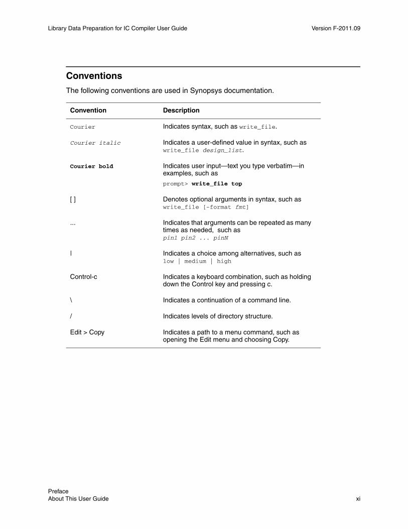
Conventions
The following conventions are used in Synopsys documentation.
Convention Description
Courier Indicates syntax, such as write_file.
Courier italic Indicates a user-defined value in syntax, such as write_file design_list.
Courier bold Indicates user input—text you type verbatim—in examples, such as
prompt> write_file top
[ ] Denotes optional arguments in syntax, such as write_file [-format fmt]
... Indicates that arguments can be repeated as many times as needed, such as pin1 pin2 ... pinN
| Indicates a choice among alternatives, such as low | medium | high
Control-c Indicates a keyboard combination, such as holding down the Control key and pressing c.
\ Indicates a continuation of a command line.
/ Indicates levels of directory structure.
Edit > Copy Indicates a path to a menu command, such as opening the Edit menu and choosing Copy.
Chapter 1: Preface About This User Guide 1-xiPreface About This User Guide xi
Library Data Preparation for IC Compiler User Guide F-2011.09Library Data Preparation for IC Compiler User Guide Version F-2011.09
Customer Support
Customer support is available through SolvNet online customer support and through contacting the Synopsys Technical Support Center.
Accessing SolvNet
SolvNet includes a knowledge base of technical articles and answers to frequently asked questions about Synopsys tools. SolvNet also gives you access to a wide range of Synopsys online services including software downloads, documentation, and technical support.
To access SolvNet, go to the following address:
https://solvnet.synopsys.com
If prompted, enter your user name and password. If you do not have a Synopsys user name and password, follow the instructions to register with SolvNet.
If you need help using SolvNet, click HELP in the top-right menu bar.
Contacting the Synopsys Technical Support Center
If you have problems, questions, or suggestions, you can contact the Synopsys Technical Support Center in the following ways:
• Open a support case to your local support center online by signing in to SolvNet at https://solvnet.synopsys.com, clicking Support, and then clicking “Open A Support Case.”
• Send an e-mail message to your local support center.
• E-mail [email protected] from within North America.
• Find other local support center e-mail addresses at http://www.synopsys.com/Support/GlobalSupportCenters/Pages
• Telephone your local support center.
• Call (800) 245-8005 from within North America.
• Find other local support center telephone numbers at http://www.synopsys.com/Support/GlobalSupportCenters/Pages
Preface Customer Support xii
1Library Data Preparation 1
Before you use IC Compiler, logical and physical libraries must be created that accurately reflect the characteristics of the available technology and cells that will be used to fabricate the chip. The physical libraries are prepared from layout data provided by an external source. The processing of this information is called library data preparation, as described the following sections:
• Libraries Used in IC Compiler
• Library Data Preparation
• Library Checking
1-1

Library Data Preparation for IC Compiler User Guide F-2011.09Library Data Preparation for IC Compiler User Guide Version F-2011.09
Libraries Used in IC Compiler
IC Compiler is a physical implementation tool that performs placement, clock tree synthesis, routing, and optimization of a chip design. To perform these tasks, it needs to read in a design netlist and both physical and logical libraries. These libraries contain information about the cells used in the design netlist.
A physical library contains information about the geometry of the cells that are placed in the design and connected with power, ground, clock, and signal routes. This library information includes the cell dimensions, border, pin locations, and mask layers, as well as technology information such as wire tracks, antenna rules, and electromigration data.
A logical library contains functional information about these cells, including the logical function, timing characteristics, and power characteristics. IC Compiler needs this information to perform analysis and optimization of the design based on the physical characteristics and the timing, power, noise, and signal integrity requirements.
Physical Libraries: Milkyway DatabaseIn typical IC Compiler flows, the physical library information is contained in the Milkyway™ database, the unifying design storage format for the Synopsys Galaxy™ implementation platform. Galaxy tools such as Design Compiler, IC Compiler, and Formality can access the design and library information contained in the database. The database contains not only leaf-level physical cell information and technology information, but also design-specific physical information such as the placement and routing of the design.
The Milkyway database is organized as a hierarchy of data files. However, you should not create, delete, copy, or edit these files directly using operating system commands such as cp and rm. Instead, you should access the database by using a Synopsys tool and use the tool commands to read, write, or change the database contents. This will ensure the consistency and integrity of the database.
In IC Compiler, you open a Milkyway database with the open_mw_lib command. By default, opening a Milkyway library makes that library accessible to the tool for both reading and writing physical design information. You can open no more than one Milkyway design library at a time. However, the design can contain references to cells contained in other Milkyway libraries, called reference libraries. Multiple users can open same design library in different sessions. However, only one user at a time can have permission to write into a Milkyway design library.
The basic unit of information in a Milkyway library is the cell. A cell is a representation of a physical structure in the chip layout, which can be something as simple as an I/O pad or as large and complex as an entire chip. You open a cell for editing by using the open_mw_cel command. The cell must be contained in the Milkyway library that is currently open.
Chapter 1: Library Data Preparation Libraries Used in IC Compiler 1-2

Library Data Preparation for IC Compiler User Guide Version F-2011.09
A design is typically built as a hierarchy of cells. The entire chip is a single cell built out of lower-level blocks, which are also cells. These blocks are built out of smaller blocks, and so on, down to the level of leaf-level cells, which are gate-level standard cells.
The Milkyway database can contain different representations of the same cell, called “views” of that cell. These are the main types of views used in IC Compiler:
• CEL view: The full layout view of a physical structure such as a via, standard cell, macro, or whole chip; contains placement, routing, pin, and netlist information for the cell
• FRAM view: An abstract representation of a cell used for placement and routing; contains only the metal blockages, allowed via areas, and pins of the cell
• ILM view: An interface logic model representation of a cell, which is created from a CEL view by the create_ilm command in IC Compiler
• FILL view: A view of metal fill, which is used for chip finishing and has no logical function, created by the signoff_metal_fill command in IC Compiler.
• CONN view: A representation of the power and ground networks of a cell, created by PrimeRail or IC Compiler and used by PrimeRail for IR drop and electromigration analysis.
• ERR view: A graphical view of physical design rule violations found by verification commands in IC Compiler such as verify_zrt_route or signoff_drc.
A design stored in a Milkyway library must have at least a CEL view, which contains all of the cell information needed for placement, routing, and mask generation. This includes placement information such as tracks, site rows, and placement blockages; routing information such as netlist, pin, route guide, and interconnect modeling information, and all mask layer geometries, which are used for final mask generation.
Each macro cell typically has both a CEL view and a FRAM view. The FRAM view is an abstraction of the cell containing only the information needed for placement and routing: the metal blockage areas where routes are not allowed, the allowed via areas, and the pin locations. The process of creating a FRAM view from a CEL view is often called blockage, pin, and via (BPV) extraction.
Each gate-level standard cell can also have both a CEL view and a FRAM view. The FRAM view is used for placement and routing, whereas the CEL view is used only for generating the final stream of mask data for chip manufacturing.
IC Compiler creates additional, temporary views in the Milkyway database while it performs tasks such as routing, pin assignment, and hierarchy flattening. It empties or deletes these views upon completion of each task. You can see these views in the directory structure of the Milkyway library during performance of the task. However, you should not attempt to
Chapter 1: Library Data Preparation Libraries Used in IC Compiler 1-3Chapter 1: Library Data Preparation Libraries Used in IC Compiler 1-3
Library Data Preparation for IC Compiler User Guide F-2011.09Library Data Preparation for IC Compiler User Guide Version F-2011.09
modify or use these views outside of the IC Compiler tool, except the case where the task is abnormally terminated. The views called ROUTE, PINASSIGN, and SMASH can be safely removed so that you can restart the corresponding process from the beginning.
Logical Libraries: Synopsys .db FilesThe cell logic, timing, and power information is typically contained in a set of Synopsys database (.db) files produced by Library Compiler. The creator of the library determines the electrical behavior of the leaf-level cells by using a simulation-based characterization tool such as Liberty NCX in combination with a circuit simulator such as HSPICE. The characterization tool produces a set of files in Liberty (.lib) format.
The Liberty (.lib) files are ASCII-format files that fully describe the cell logic, timing, and power characteristics of the leaf-level logic cells. Library Compiler compiles the .lib files to produce .db files, which contain the same information as the .lib files, but in a compiled binary format that is more efficient for Galaxy tools to use.
In IC Compiler, you specify the .db files to use for the design by setting the search_path, target_library, and link_library variables:
• The search_path variable specifies the directory paths in which the .db files and other files needed by the tool can be found.
• The target_library variable specifies the .db library files containing the logic cells that can be used for optimization, for example, different NAND gates having various areas, drive strengths, delays, and power usage.
• The link_library variable specifies the .db libraries containing all the logic cells that can be used to resolve hierarchical references in the design during execution of the link command.
For example, an IC Compiler script might contain commands like these:
set_app_var search_path "/remote/tech/libs ~/LIBS/mysdc ~/LIBS/def"set_app_var target_library "stdcell.db"set_app_var link_library "* stdcell.db macrocell.db pll.db memory.db"
The list of libraries set in the link_library variable should include all of those set in the target_library variable. The link_library variable should also include an asterisk character, which causes the link command to search through all designs already loaded into memory to find referenced cells. It should also include the names of any libraries containing cells that exist in the design but are not targets of optimization, such as macro and RAM cells.
A design attribute (not variable) called local_link_library can be used to specify additional libraries that can be used for design linking. It can be set with the set_local_link_library command.
Chapter 1: Library Data Preparation Libraries Used in IC Compiler 1-4

Library Data Preparation for IC Compiler User Guide Version F-2011.09
The names of the cells in the logical libraries must match the names of the corresponding cells in the physical libraries in the Milkyway database. You can verify that the logical and physical libraries properly match by using the check_library command.
Library Data Preparation
Before you use IC Compiler, logical and physical libraries must be created that accurately reflect the characteristics of the available technology and contain the standard cells that will be used to fabricate the chip. IC Compiler needs these libraries to place, route, analyze, and optimize the chip design.
The Synopsys tools for creating .db logical libraries are Liberty NCX, HSPICE, and Library Compiler. Liberty NCX and HSPICE characterize the standard cells and generate a set of .lib files that describe the cell behavior, and Library Compiler compiles the .lib files to produce the .db files. The use of these tools is beyond the scope of this user guide. For more information about creating .db files, see the documentation for the applicable products.
The focus of this user guide is the preparation of physical library data in the Milkyway database format from the technology information provided by an outside source. This information is usually provided in one of the following standard data interchange formats:
• GDSII stream format, a well-established industry-standard data exchange format for integrated circuit layout information
• OASIS, a newer data stream format designed as an improved replacement for GDSII
• LEF/DEF, a set of standard data exchange formats for physical libraries (Library Exchange Format) and design data (Design Exchange Format)
To convert this information into the Milkyway database format, you need to read in the layout information in the provided format, add library information that is not provided in the exchange format, and write the data out to the Milkyway database. In addition, you need to prepare the standard cells for use in IC Compiler by identifying power and ground pins, flattening cells that are hierarchical, extracting FRAM views from CEL views, setting the place and route boundaries, and defining the wire tracks.
The tool for performing these tasks is the Milkyway Environment. The conversion of GDSII and OASIS data streams to the Milkyway format is described in Chapter 3, “Library Preparation Using GDSII and OASIS.” The conversion of LEF/DEF library and design data to the Milkyway format is described in Chapter 4, “Library Preparation Using LEF/DEF.” The further preparation of cells for use in IC Compiler is described in Chapter 5, “Library Cell Preparation.”
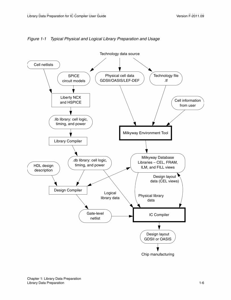
Figure 1-1 shows the typical library preparation and usage flow for IC Compiler.
Chapter 1: Library Data Preparation Library Data Preparation 1-5Chapter 1: Library Data Preparation Library Data Preparation 1-5
Library Data Preparation for IC Compiler User Guide F-2011.09Library Data Preparation for IC Compiler User Guide Version F-2011.09
Figure 1-1 Typical Physical and Logical Library Preparation and Usage
Technology data source
Chip manufacturing
Liberty NCXand HSPICE
Physical cell dataGDSII/OASIS/LEF-DEF
Technology file.tf
Cell netlists
Milkyway Environment Tool
SPICEcircuit models
.lib library: cell logic, timing, and power
Library Compiler
.db library: cell logic,timing, and power
Cell informationfrom user
Milkyway DatabaseLibraries – CEL, FRAM,
ILM, and FILL views
IC Compiler
Design Compiler
Gate-levelnetlist
HDL design description
Design layoutGDSII or OASIS
Physical library data
Design layout data (CEL views)
Logicallibrary data
Chapter 1: Library Data Preparation Library Data Preparation 1-6

Library Data Preparation for IC Compiler User Guide Version F-2011.09
Milkyway Library Editing in IC CompilerIC Compiler provides commands to perform several types of library data preparation tasks. You can open a Milkyway library and create, copy, and delete cells contained in the open library. You can also perform blockage, pin, and via extraction from CEL views to create FRAM views for placement and routing.
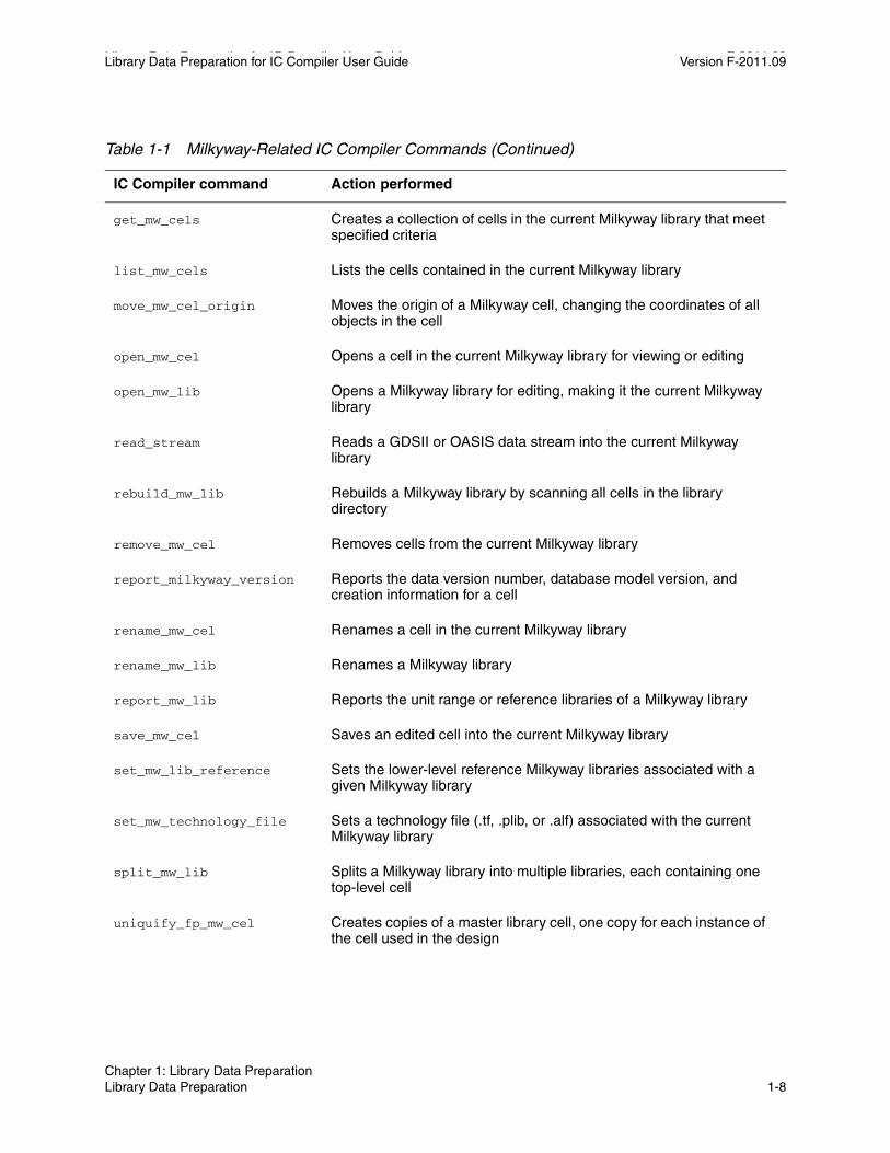
Table 1-1 lists and briefly describes the IC Compiler commands used to open a Milkyway library and to report, check, or change the library contents.
Table 1-1 Milkyway-Related IC Compiler Commands
IC Compiler command Action performed
archive_design Archives a Milkyway design
check_library Checks logical and physical libraries for quality and consistency
close_mw_cel Closes one or more open cells in the open Milkyway library
close_mw_lib Closes the current Milkyway library
convert_mw_lib Converts the design data in a Milkyway library to the current database model version or to the previous version
copy_mw_cel Copies a cell to create a new cell in the current Milkyway library
copy_mw_lib Copies a Milkyway library
create_boundary Creates or modifies a boundary of a design or a library cell
create_macro_fram Extracts a macro cell from a CEL view to make a FRAM view
create_mw_cel Creates a new cell in the current Milkyway library
create_mw_lib Creates a new Milkyway library
current_mw_cel Specifies or reports the current cell on which commands operate
current_mw_lib Reports the current Milkyway library; creates a collection containing that library
decrypt_lib Decrypts a library encrypted with the encrypt_lib command in the Milkyway Environment
extract_blockage_pin_via Extracts blockage, pin, and via information from a CEL view to make a FRAM view
Chapter 1: Library Data Preparation Library Data Preparation 1-7Chapter 1: Library Data Preparation Library Data Preparation 1-7
Library Data Preparation for IC Compiler User Guide F-2011.09Library Data Preparation for IC Compiler User Guide Version F-2011.09
get_mw_cels Creates a collection of cells in the current Milkyway library that meet specified criteria
list_mw_cels Lists the cells contained in the current Milkyway library
move_mw_cel_origin Moves the origin of a Milkyway cell, changing the coordinates of all objects in the cell
open_mw_cel Opens a cell in the current Milkyway library for viewing or editing
open_mw_lib Opens a Milkyway library for editing, making it the current Milkyway library
read_stream Reads a GDSII or OASIS data stream into the current Milkyway library
rebuild_mw_lib Rebuilds a Milkyway library by scanning all cells in the library directory
remove_mw_cel Removes cells from the current Milkyway library
report_milkyway_version Reports the data version number, database model version, and creation information for a cell
rename_mw_cel Renames a cell in the current Milkyway library
rename_mw_lib Renames a Milkyway library
report_mw_lib Reports the unit range or reference libraries of a Milkyway library
save_mw_cel Saves an edited cell into the current Milkyway library
set_mw_lib_reference Sets the lower-level reference Milkyway libraries associated with a given Milkyway library
set_mw_technology_file Sets a technology file (.tf, .plib, or .alf) associated with the current Milkyway library
split_mw_lib Splits a Milkyway library into multiple libraries, each containing one top-level cell
uniquify_fp_mw_cel Creates copies of a master library cell, one copy for each instance of the cell used in the design
Table 1-1 Milkyway-Related IC Compiler Commands (Continued)
IC Compiler command Action performed
Chapter 1: Library Data Preparation Library Data Preparation 1-8

Library Data Preparation for IC Compiler User Guide Version F-2011.09
IC Compiler has some commands that resemble Milkyway Environment library data preparation commands but are not used for library data preparation:
• The read_lib and write_lib commands can read and write library files of various types. However, they are not used to read or write Milkyway data files.
• The read_def and write_def commands can read and write DEF files. However, they are used only to read and write floorplanning and scan chain information in the DEF file, not standard cell library information.
Library Preparation in the Milkyway EnvironmentThe Milkyway Environment is a separate, standalone tool for preparing physical libraries from the layout data provided by an outside source. The tool offers interactive, menu-based GUI command entry, Tcl command entry, and Tcl script execution. The tool allows you to perform the following tasks, which are essential for library data preparation:
• Create standard cell libraries
• Import cell data in GDSII, OASIS, and LEF/DEF format
• Specify technology information
• Write technology information to a file
• Flatten cell hierarchy
• Specify power and ground port types
• Optimize the standard cell layout
• Extract blockage, pin, and via information to make FRAM views
• Set place and route boundaries
• Define wire tracks
write_mw_lib_files Writes the library technology information or library reference information to a file
write_stream Writes one or more cells in the Milkyway database to a GDSII or OASIS data stream
Table 1-1 Milkyway-Related IC Compiler Commands (Continued)
IC Compiler command Action performed
Chapter 1: Library Data Preparation Library Data Preparation 1-9Chapter 1: Library Data Preparation Library Data Preparation 1-9

Library Data Preparation for IC Compiler User Guide F-2011.09Library Data Preparation for IC Compiler User Guide Version F-2011.09
Usage of the Milkyway Environment is described in detail in Chapter 2, “Milkyway Environment Tool.”
Library Checking
After you prepare new logic libraries in .db format or physical libraries in Milkyway format, you should check the libraries for accuracy and consistency by using the check_library command. This command is available in both IC Compiler and the Milkyway Environment.
The check_library command checks the physical library quality, the consistency between the physical library and the corresponding logical library, and the consistency between multiple logic libraries. It verifies the consistency of cell names, pin names, area values, bus naming conventions, operating condition scaling, antenna rules, and so on. It generates a detailed report on any errors or inconsistencies that are found.
Usage of the check_library command is described in detail in Chapter 6, “Library Checking.”
Chapter 1: Library Data Preparation Library Checking 1-10
2Milkyway Environment Tool 2
The Milkyway Environment is a standalone tool for preparing physical libraries from the layout data provided by an outside source. The tool offers interactive, menu-based GUI command entry, Tcl command entry, and Tcl script execution. Usage of the tool is described in the following sections:
• Starting the Milkyway Environment
• Command Entry Methods
• Online Help
• Library Data Preparation Flow
• Creating a New Milkyway Library
2-1
Library Data Preparation for IC Compiler User Guide F-2011.09Library Data Preparation for IC Compiler User Guide Version F-2011.09
Starting the Milkyway Environment
The Milkyway Environment tool allows you to perform several tasks that are essential for library data preparation. Before you can use the tool, the software must be installed and licensed at your site. For information on installation and licensing, see the documentation that comes with the product release.
Before you start the Milkyway Environment tool, might want to change to the directory containing your design files. This will make it easier to access your working files.
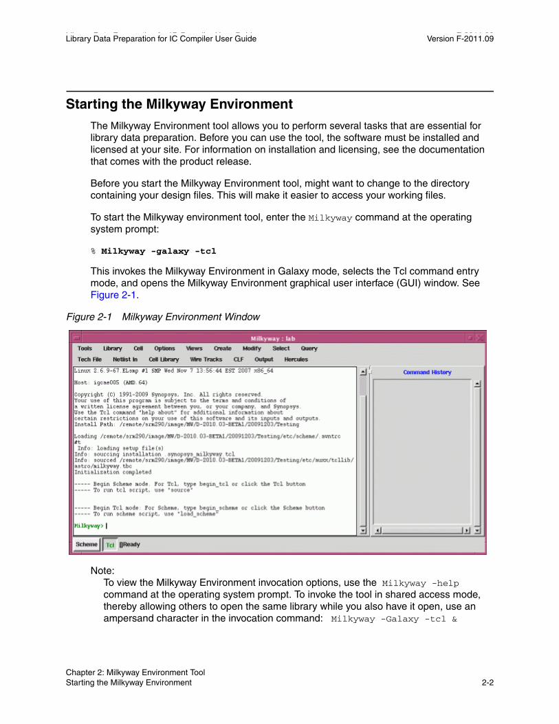
To start the Milkyway environment tool, enter the Milkyway command at the operating system prompt:
% Milkyway -galaxy -tcl
This invokes the Milkyway Environment in Galaxy mode, selects the Tcl command entry mode, and opens the Milkyway Environment graphical user interface (GUI) window. See Figure 2-1.
Figure 2-1 Milkyway Environment Window
Note: To view the Milkyway Environment invocation options, use the Milkyway -help command at the operating system prompt. To invoke the tool in shared access mode, thereby allowing others to open the same library while you also have it open, use an ampersand character in the invocation command: Milkyway -Galaxy -tcl &
Chapter 2: Milkyway Environment Tool Starting the Milkyway Environment 2-2
Library Data Preparation for IC Compiler User Guide Version F-2011.09
You control the Milkyway Environment tool by using the GUI menu commands at the top or by entering Tcl commands or Scheme commands. The large text area in the middle is for displaying system messages and entering commands. The command history appears in a separate window on the right.
To exit from the Milkyway Environment tool and end the session, enter the command exit at the bottom or use the GUI menu command Tools > Quit.
Command Entry Methods
The Milkyway Environment offers three methods of command entry:
• GUI menu commands
• Tcl commands
• Scheme commands
The GUI menu commands and associated dialog boxes provide interactive guidance for performing various tasks such as opening and closing Milkyway libraries, opening and closing cells, importing physical data in GDSII, OASIS, or LEF/DEF format, creating FRAM views from CEL views, and exporting physical design data to external tools.
The Tcl command interface provides a method for entering commands that is familiar to Synopsys product users. You enter Tcl commands at the Milkyway> command prompt, similar to other Tcl-based tools such as Design Compiler, IC Compiler, and PrimeTime.
The Scheme command interface is a command-line interface that is familiar to users of the older Synopsys place-and-route and floorplanning tools, Astro and Jupiter XT. This command interface is provided mainly for the benefit of customers still using the older tools.
The Milkyway Environment can operate in the Tcl or Scheme mode but not both modes at the same time. To switch from one mode to the other, click on the Scheme or Tcl button in the lower-left corner of the Milkyway Environment window. The GUI menus work in both the Scheme and Tcl modes.
GUI Menu Command EntryThe GUI command menus provide an easy-to-use, directed method to enter commands and to perform all kinds of tasks. The top-level commands are displayed at the top of the Milkyway Environment GUI window, as shown in Figure 2-2.
Chapter 2: Milkyway Environment Tool Command Entry Methods 2-3Chapter 2: Milkyway Environment Tool Command Entry Methods 2-3

Library Data Preparation for IC Compiler User Guide F-2011.09Library Data Preparation for IC Compiler User Guide Version F-2011.09
Figure 2-2 Top-Level Menu Commands
Typically, the first action taken in a session is to open an existing Milkyway library. To do this, choose Library > Open, which displays the Open Library dialog box as shown in Figure 2-3.
Figure 2-3 Library > Open Dialog Box
You can enter the Milkyway library name and the directory path to the library in the text boxes provided, or you can browse and select the Milkyway library from a directory tree. Clicking the Browse button opens the Browse Library dialog box as shown in Figure 2-4.
Figure 2-4 Browse Library Dialog Box
Chapter 2: Milkyway Environment Tool Command Entry Methods 2-4
Library Data Preparation for IC Compiler User Guide Version F-2011.09
You can browse the directory tree to find the desired Milkyway library. Each Milkyway library is displayed as a brown folder marked with the letter “L.” Select the desired Milkyway library, click Hide to close the Browse Library dialog box, and then click OK in the Open Library dialog box to open the library.
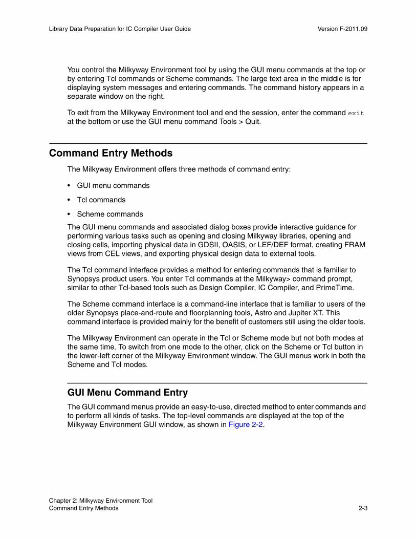
The next action might be to open a cell. To do this, choose Cell > Open, which displays the Open Cell dialog box. Then click the Browse button to open the Browse Cell dialog box, which lists the open Milkyway library and other referenced Milkyway libraries, as shown in Figure 2-5.
Figure 2-5 Cell > Open and Browse Cell Dialog Boxes
From the Libraries list on the right, select the desired Milkyway library. The cells contained in that library appear in the Cells list. Select the desired cell, and the cell name appears in the Open Cell dialog box. Click Hide to close the Browse Cell dialog box, and then click OK to open the cell.
Note: If you choose a cell from a reference library rather than the open library, you must enable the read-only option in the Open Cell dialog box. Only cells in the currently open Milkyway library can be opened with read/write privileges.
When you open a cell, the Milkyway Environment displays the cell layout graphically in a new window like the one shown in Figure 2-6.
Chapter 2: Milkyway Environment Tool Command Entry Methods 2-5Chapter 2: Milkyway Environment Tool Command Entry Methods 2-5
Library Data Preparation for IC Compiler User Guide F-2011.09Library Data Preparation for IC Compiler User Guide Version F-2011.09
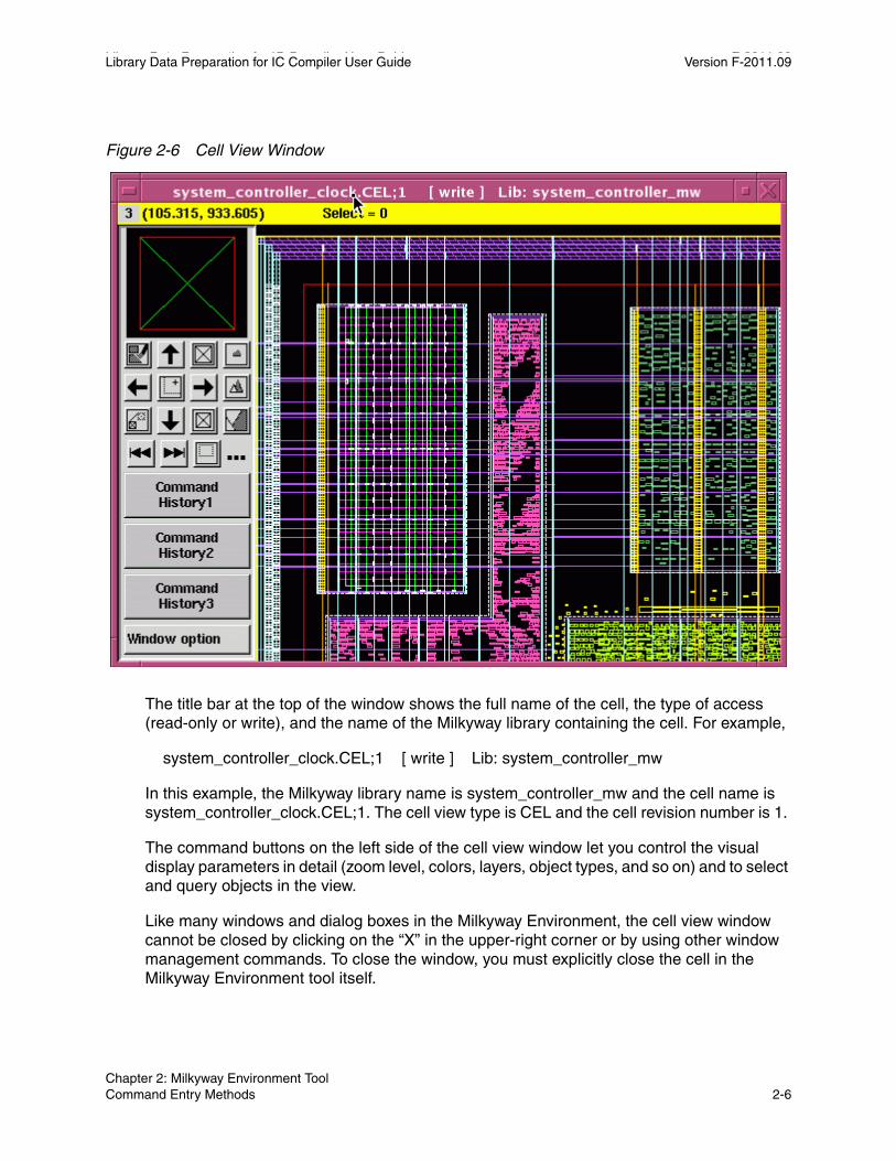
Figure 2-6 Cell View Window
The title bar at the top of the window shows the full name of the cell, the type of access (read-only or write), and the name of the Milkyway library containing the cell. For example,
system_controller_clock.CEL;1 [ write ] Lib: system_controller_mw
In this example, the Milkyway library name is system_controller_mw and the cell name is system_controller_clock.CEL;1. The cell view type is CEL and the cell revision number is 1.
The command buttons on the left side of the cell view window let you control the visual display parameters in detail (zoom level, colors, layers, object types, and so on) and to select and query objects in the view.
Like many windows and dialog boxes in the Milkyway Environment, the cell view window cannot be closed by clicking on the “X” in the upper-right corner or by using other window management commands. To close the window, you must explicitly close the cell in the Milkyway Environment tool itself.
Chapter 2: Milkyway Environment Tool Command Entry Methods 2-6
Library Data Preparation for IC Compiler User Guide Version F-2011.09
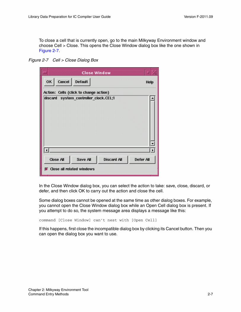
To close a cell that is currently open, go to the main Milkyway Environment window and choose Cell > Close. This opens the Close Window dialog box like the one shown in Figure 2-7.
Figure 2-7 Cell > Close Dialog Box
In the Close Window dialog box, you can select the action to take: save, close, discard, or defer, and then click OK to carry out the action and close the cell.
Some dialog boxes cannot be opened at the same time as other dialog boxes. For example, you cannot open the Close Window dialog box while an Open Cell dialog box is present. If you attempt to do so, the system message area displays a message like this:
command [Close Window] can’t nest with [Open Cell]
If this happens, first close the incompatible dialog box by clicking its Cancel button. Then you can open the dialog box you want to use.
Chapter 2: Milkyway Environment Tool Command Entry Methods 2-7Chapter 2: Milkyway Environment Tool Command Entry Methods 2-7
Library Data Preparation for IC Compiler User Guide F-2011.09Library Data Preparation for IC Compiler User Guide Version F-2011.09
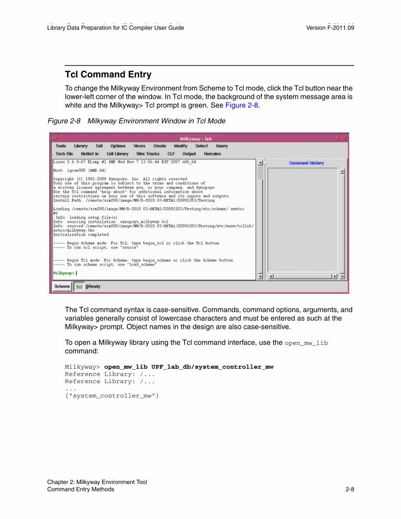
Tcl Command EntryTo change the Milkyway Environment from Scheme to Tcl mode, click the Tcl button near the lower-left corner of the window. In Tcl mode, the background of the system message area is white and the Milkyway> Tcl prompt is green. See Figure 2-8.
Figure 2-8 Milkyway Environment Window in Tcl Mode
The Tcl command syntax is case-sensitive. Commands, command options, arguments, and variables generally consist of lowercase characters and must be entered as such at the Milkyway> prompt. Object names in the design are also case-sensitive.
To open a Milkyway library using the Tcl command interface, use the open_mw_lib command:
Milkyway> open_mw_lib UPF_lab_db/system_controller_mwReference Library: /...Reference Library: /......{"system_controller_mw"}
Chapter 2: Milkyway Environment Tool Command Entry Methods 2-8

Library Data Preparation for IC Compiler User Guide Version F-2011.09
To open a cell in a Milkyway library, use the open_mw_cel command:
Milkyway> open_mw_cel -library system_controller_mw \ system_controller_clockInformation: Opened "system_controller_clock.CEL;1 from "/..."{"system_controller_clock"}
The cell is displayed in a GUI viewing window, just like opening the cell using the GUI command Cell > Open.
For detailed information on using Tcl commands and Tcl scripting, procedures, and collections, see the Using Tcl With Synopsys Tools manual, available on SolvNet.
Tcl HelpTo get help on Tcl commands, use the help command. The help command by itself lists all the Tcl commands. To get a list of all commands containing the word “cell,” use the following command:
Milkyway> help *cell* create_cell # creates cell flatten_cell # Flatten a Milkyway design get_cells # create a collection of cells ...
To get the syntax for a particular command, use the -help option of that command:
Milkyway> create_cell -help create_cell # creates cell -from_design design_name (design from which to create the cell) [-from_library library_name (library from which to create the cell) [-rotation 90 | 180 | 270] (Degree to which you want the cell rotated) ...
To get detailed information about a command, use the man command:
Milkyway> man create_cellcreate_cell 2. Synopsys Commands Command Reference
NAME create_cell Creates a cell in the current design.
SYNTAX int create_cell [-from_library library] [-rotation {90 | 180 | 270}] [-mirror {x | y}]
Chapter 2: Milkyway Environment Tool Command Entry Methods 2-9Chapter 2: Milkyway Environment Tool Command Entry Methods 2-9
Library Data Preparation for IC Compiler User Guide F-2011.09Library Data Preparation for IC Compiler User Guide Version F-2011.09
[-ignore_eco] [-without_check_status] -origin {x y} -from_design from_design cell_name
string cell_name string from_design string from_libraryARGUMENTS ...
DESCRIPTION ...
EXAMPLES
...SEE ALSO ...
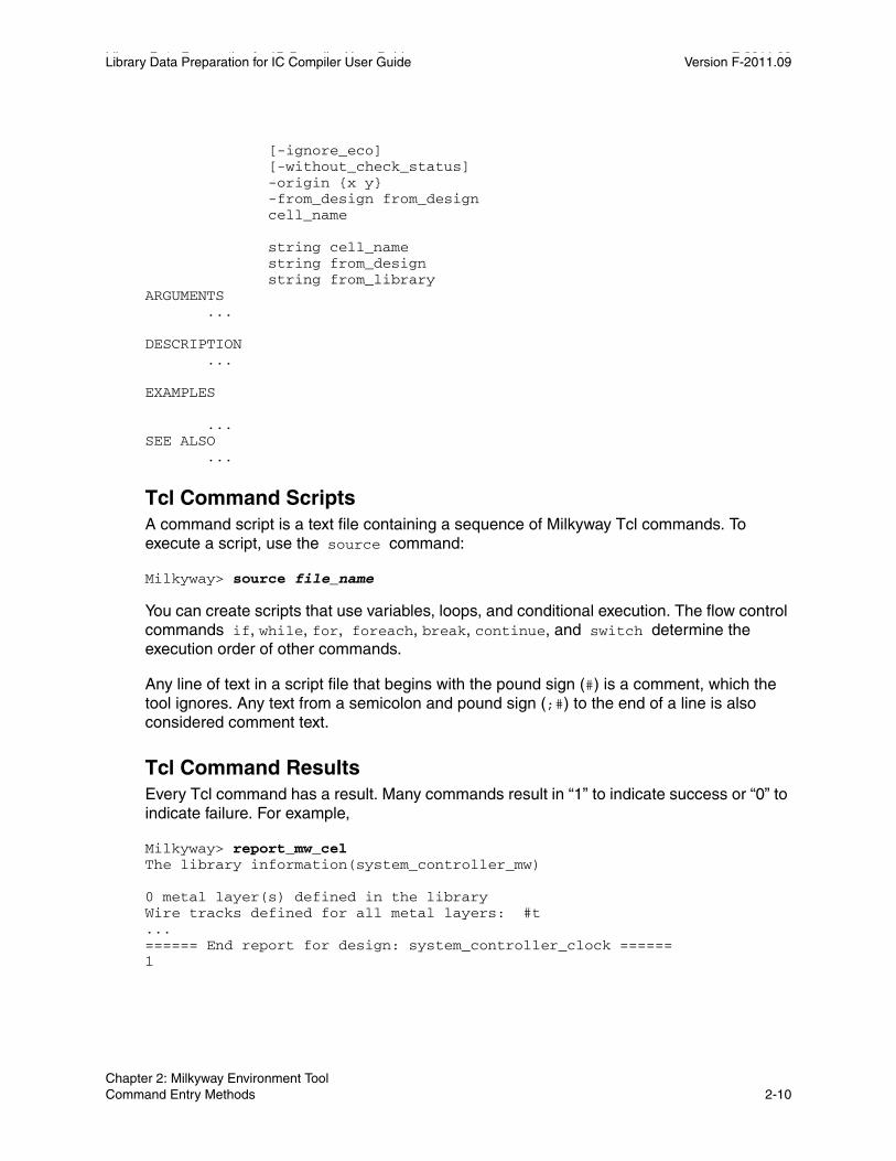
Tcl Command ScriptsA command script is a text file containing a sequence of Milkyway Tcl commands. To execute a script, use the source command:
Milkyway> source file_name
You can create scripts that use variables, loops, and conditional execution. The flow control commands if, while, for, foreach, break, continue, and switch determine the execution order of other commands.
Any line of text in a script file that begins with the pound sign (#) is a comment, which the tool ignores. Any text from a semicolon and pound sign (;#) to the end of a line is also considered comment text.
Tcl Command ResultsEvery Tcl command has a result. Many commands result in “1” to indicate success or “0” to indicate failure. For example,
Milkyway> report_mw_celThe library information(system_controller_mw)
0 metal layer(s) defined in the libraryWire tracks defined for all metal layers: #t...====== End report for design: system_controller_clock ======1
Chapter 2: Milkyway Environment Tool Command Entry Methods 2-10

Library Data Preparation for IC Compiler User Guide Version F-2011.09
For many other commands, the result is a collection. For example, the result of the get_nets command is a collection of the nets in the cell:
Milkyway> get_nets{"n704", "feed_data_out[8]", “thirtyfirst_row[0]”, ... }
Tcl VariablesThe tool offers many options that you control by setting variables. To set a variable, you use the set_app_var command:
Milkyway> set_app_var variable_name variable_settingreplace all nt_shell with Milkyway
When you set a variable, the displayed result is simply the new setting for the variable. For example,
Milkyway> set_app_var sh_enable_page_mode truetrue
To find out the current setting for a variable, use the printvar command. For example,
Milkyway> printvar sh_enable_page_modesh_enable_page_mode = "true"
You can use the wildcard character (*) to view multiple related settings. For example, to see a list of shell-related variables, enter
Milkyway> printvar sh_*sh_allow_tcl_with_set_app_var = "true"sh_allow_tcl_with_set_app_var_no_message_list = "true"sh_arch ="amd64"...
Scheme Command EntryThe Scheme command interface is provided mainly for the benefit of customers still using the older Synopsys tools Astro and Jupiter XT. For users of IC Compiler, either Tcl commands or GUI menu commands are recommended.
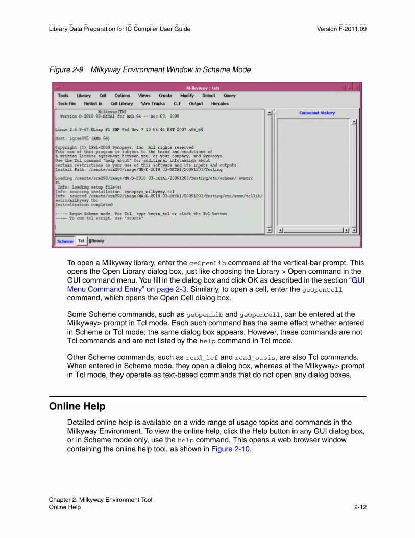
To change the Milkyway Environment from Tcl to Scheme mode, click the Scheme button in the lower-left corner of the window. In Scheme mode, the background of the system message area is gray, as shown in Figure 2-9. You enter Scheme commands at the bottom of this area.
Chapter 2: Milkyway Environment Tool Command Entry Methods 2-11Chapter 2: Milkyway Environment Tool Command Entry Methods 2-11
Library Data Preparation for IC Compiler User Guide F-2011.09Library Data Preparation for IC Compiler User Guide Version F-2011.09
Figure 2-9 Milkyway Environment Window in Scheme Mode
To open a Milkyway library, enter the geOpenLib command at the vertical-bar prompt. This opens the Open Library dialog box, just like choosing the Library > Open command in the GUI command menu. You fill in the dialog box and click OK as described in the section “GUI Menu Command Entry” on page 2-3. Similarly, to open a cell, enter the geOpenCell command, which opens the Open Cell dialog box.
Some Scheme commands, such as geOpenLib and geOpenCell, can be entered at the Milkyway> prompt in Tcl mode. Each such command has the same effect whether entered in Scheme or Tcl mode; the same dialog box appears. However, these commands are not Tcl commands and are not listed by the help command in Tcl mode.
Other Scheme commands, such as read_lef and read_oasis, are also Tcl commands. When entered in Scheme mode, they open a dialog box, whereas at the Milkyway> prompt in Tcl mode, they operate as text-based commands that do not open any dialog boxes.
Online Help
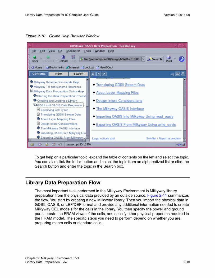
Detailed online help is available on a wide range of usage topics and commands in the Milkyway Environment. To view the online help, click the Help button in any GUI dialog box, or in Scheme mode only, use the help command. This opens a web browser window containing the online help tool, as shown in Figure 2-10.
Chapter 2: Milkyway Environment Tool Online Help 2-12
Library Data Preparation for IC Compiler User Guide Version F-2011.09
Figure 2-10 Online Help Browser Window
To get help on a particular topic, expand the table of contents on the left and select the topic. You can also click the Index button and select the topic from an alphabetized list or click the Search button and enter the topic in the Search box.
Library Data Preparation Flow
The most important task performed in the Milkyway Environment is Milkyway library preparation from the physical data provided by an outside source. Figure 2-11 summarizes the flow. You start by creating a new Milkyway library. Then you import the physical data in GDSII, OASIS, or LEF/DEF format and provide any additional information needed to create Milkyway CEL models for the cells in the library. You then specify the power and ground ports, create the FRAM views of the cells, and specify other physical properties required in the FRAM model. The specific steps you need to perform depend on whether you are preparing macro cells or standard cells.
Chapter 2: Milkyway Environment Tool Library Data Preparation Flow 2-13Chapter 2: Milkyway Environment Tool Library Data Preparation Flow 2-13

Library Data Preparation for IC Compiler User Guide F-2011.09Library Data Preparation for IC Compiler User Guide Version F-2011.09
Figure 2-11 Library Preparation Flow in the Milkyway Environment
Technology file
Identify power and ground portsset_attribute port_type ...
Import GDSII or OASISCell Library > Stream In
or read_oasis
Flatten macro cell hierarchyCell Library > Smash
Extract BPV to make FRAMCell Library > Blockage, Pin & Via
Set place & route boundaryCell Library > Set PR Boundary
Set multiple-height PR boundaryCell Library > Multi Height Cell
Define wire tracksWire Tracks > Define Unit Tile ...
Create Milkyway LibraryLibrary > Create
Import LEFCell Library > LEF In or
Cell Library > Library Preparation
Macro cells done
Extract BPV to make FRAMCell > Make Macro Abstract
Standard cells done
LEF fileGDSII stream file
OASIS stream file
Cell type definition
Layer mapping
Macro cell preparation Standard cell preparation
The first step, creating a new Milkyway library, is described in the next section, “Creating a New Milkyway Library.” The next step, importing the physical data, is described in Chapter 3, “Library Preparation Using GDSII and OASIS” and Chapter 4, “Library Preparation Using LEF/DEF.” The remaining steps are described in Chapter 5, “Library Cell Preparation.”
Chapter 2: Milkyway Environment Tool Library Data Preparation Flow 2-14

Library Data Preparation for IC Compiler User Guide Version F-2011.09
Creating a New Milkyway Library
The first step in Milkyway library preparation is to create a new library. You must have a technology (.tf) file to specify the basic parameters for the library, and the cells you later add to the library must be consistent with that technology file.
To create a new Milkyway library using the Milkyway Environment GUI, choose Library > Create. This opens the Create Library dialog box. See Figure 2-12.
Figure 2-12 Library > Create Dialog Box
Enter the new library name, the name of the associated technology (.tf) file, and the hierarchy separator character. Then click OK to create the library.
The library name must start with an alphabetic character. The remaining characters can be alphabetic, numeric, or the underscore character.
The hierarchy separator character must be one of the following: / . | # @ ^
The Technology File Checking Mode options specify the level of detail provided in error messages during library development. Select “Library Developer Mode” to get more detailed messages if you are the library developer. Otherwise, keep the “Library End-User Mode” setting.
You can also create a new library by using the create_mw_lib command at the Milkyway> Tcl prompt or the icc_shell> prompt in IC Compiler. The create_mw_lib command options let you specify the same options as the Create Library dialog box, plus additional options to specify the reference libraries and bus naming style. For details, see the man page.
Chapter 2: Milkyway Environment Tool Creating a New Milkyway Library 2-15Chapter 2: Milkyway Environment Tool Creating a New Milkyway Library 2-15
Library Data Preparation for IC Compiler User Guide F-2011.09Library Data Preparation for IC Compiler User Guide Version F-2011.09
Chapter 2: Milkyway Environment Tool Creating a New Milkyway Library 2-16
3Library Preparation Using GDSII and OASIS 3
To prepare a Milkyway reference library from physical cell data, you import the data as a GDSII or OASIS data stream into the Milkyway Environment and translate that data into the Milkyway database format. Importing GDSII and OASIS data streams into the Milkyway database and exporting the Milkyway database to GDSII and OASIS output streams are described in the following sections:
• GDSII to Milkyway
• Milkyway to GDSII
• OASIS to Milkyway
• Milkyway to OASIS
3-1
Library Data Preparation for IC Compiler User Guide F-2011.09Library Data Preparation for IC Compiler User Guide Version F-2011.09
GDSII to Milkyway
The GDSII stream format is an industry-standard data exchange format for integrated circuit layout information. A GDSII file contains information about layers, wire paths, boundaries, structures, arrays, and text labels in the cell or chip layout.
When an outside source provides library cell information in GDSII format, you need to read the data file into the Milkyway Environment and convert the data stream into a cell library in the Milkyway database. In addition to the GDSII file, you typically provide a cell-type definition file and a layer mapping file to specify how to translate the data.
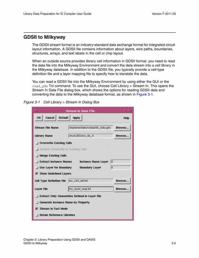
You can read a GDSII file into the Milkyway Environment by using either the GUI or the read_gds Tcl command. To use the GUI, choose Cell Library > Stream In. This opens the Stream In Data File dialog box, which shows the options for reading GDSII data and converting the data to the Milkyway database format, as shown in Figure 3-1.
Figure 3-1 Cell Library > Stream In Dialog Box
Chapter 3: Library Preparation Using GDSII and OASIS GDSII to Milkyway 3-2

Library Data Preparation for IC Compiler User Guide Version F-2011.09
You must at least specify the Stream File Name, which is the name of GDSII file being read in, and the Library Name, which is the name of the Milkyway reference library in which to store the translated data. You might also want to provide the following additional information:
• A cell-type definition file, which identifies the cell types: standard cell, pad cell, filler cell, macro, and so on. The cell function affects the translation of physical data to the Milkyway format. If this file is not provided, all cells are assumed to be standard cells. For information about the file format, see the next subsection, “Cell-Type Definition File.”
• A layer mapping file, which identifies the corresponding layer names in the GDSII and Milkyway database formats. If this file is not provided, the layer names defined in the GDSII data stream are retained in the Milkyway database. For information about the file format, see “Layer Mapping File: GDSII or OASIS to Milkyway” on page 3-5.
Some of the dialog box options specify how to handle cells that already exist in the Milkyway library. Others determine how to handle cell boundary layers and layers not defined in the layer mapping file. For a detailed explanation of each option, see the Milkyway Environment online help for the Scheme command auStreamIn.
After you set the dialog box options, click OK. The Milkyway Environment tool reads the GDSII data stream, creates a CEL view for each cell, and stores the cells into the specified Milkyway library.
Instead of using the GUI, you can use the equivalent Tcl command in the Milkyway Environment, read_gds. The Tcl command offers a few options that are not available in the GUI dialog box. These options are related to the processing of text in the GDSII data stream. For details, see the man page for the read_gds command, available on SolvNet and in the Milkyway Environment tool.
In IC Compiler, you can read in GDSII data with the read_stream command. For details, see “Reading and Writing GDSII and OASIS in IC Compiler” on page 7-15.
Cell-Type Definition FileA GDSII or OASIS stream file contains physical information about library cells, but it does not specify the cell types. The Milkyway database needs the cell type information so that it can properly process the cells for use by IC Compiler.
You specify the cell types in a text file. The file contains a list of cell types and the names of cells in the GDSII or OASIS data stream matching that type. For example, consider the following simple cell-type definition file:
gdsMacroCell BLOCK1 BLOCK2gdsOtherCell TEST VIA1 RCAP FEED2gdsStandardCell *
Chapter 3: Library Preparation Using GDSII and OASIS GDSII to Milkyway 3-3Chapter 3: Library Preparation Using GDSII and OASIS GDSII to Milkyway 3-3
Library Data Preparation for IC Compiler User Guide F-2011.09Library Data Preparation for IC Compiler User Guide Version F-2011.09
This file identifies the cells BLOCK1 and BLOCK2 as macro cells, the cells TEST, VIA1, RCAP, and FEED2 and “other” type cells, all other cells as standard cells. Later in the library data preparation flow, each type of cell receives a different type of processing. Cells in the “other” category are translated to Milkyway format but not processed any further.
Any cells in the GDSII or OASIS data stream that are not listed in the cell-type definition file are considered standard cells. In the absence of a cell-type definition file, all cells are considered standard cells.
In general, the cell-type definition file contains statements in the following format:
cellType cellNameListcellType cellNameListcellType cellNameList...
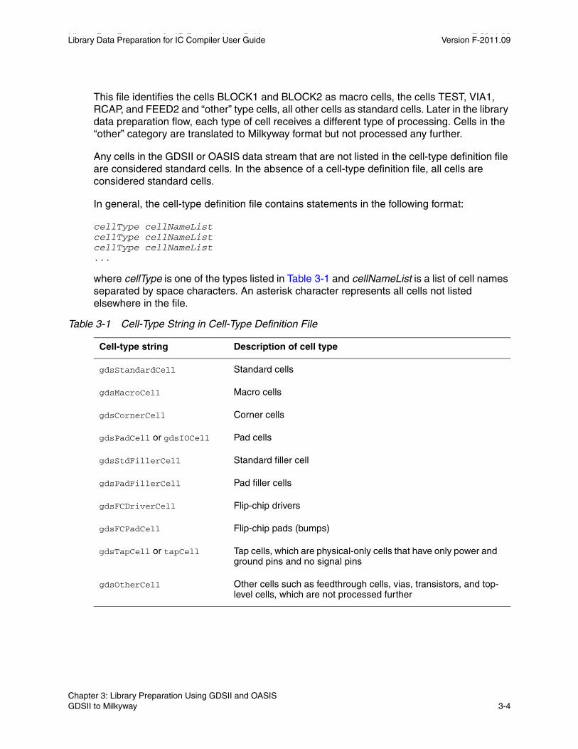
where cellType is one of the types listed in Table 3-1 and cellNameList is a list of cell names separated by space characters. An asterisk character represents all cells not listed elsewhere in the file.
Table 3-1 Cell-Type String in Cell-Type Definition File
Cell-type string Description of cell type
gdsStandardCell Standard cells
gdsMacroCell Macro cells
gdsCornerCell Corner cells
gdsPadCell or gdsIOCell Pad cells
gdsStdFillerCell Standard filler cell
gdsPadFillerCell Pad filler cells
gdsFCDriverCell Flip-chip drivers
gdsFCPadCell Flip-chip pads (bumps)
gdsTapCell or tapCell Tap cells, which are physical-only cells that have only power and ground pins and no signal pins
gdsOtherCell Other cells such as feedthrough cells, vias, transistors, and top-level cells, which are not processed further
Chapter 3: Library Preparation Using GDSII and OASIS GDSII to Milkyway 3-4
Library Data Preparation for IC Compiler User Guide Version F-2011.09
You can add a comment by inserting a semicolon. Text is ignored from the semicolon to the end of the line.
In the Milkyway Environment GUI, you can define or redefine a cell type for an existing cell by choosing Cell Library > Mark Cell Type.
Layer Mapping File: GDSII or OASIS to MilkywayEach geometric object in a layout database has an associated layer number and data type number. In GDSII and OASIS, the layer number and data type are integers ranging from 0 to 32767. The Milkyway database supports layer numbers and data types ranging from 0 to 255. By default, numbers from 0 to 255 are left unchanged by a translation of physical data from GDSII or OASIS to Milkyway format. Any GDSII and OASIS layer or data type numbers greater than 255 must be translated to lower numbers when they are read into the Milkyway database.
To have the layer numbers or data types changed by the translation process, specify the desired layer-to-layer mapping in a file and invoke that file in the Cell Library > Stream In dialog box, in the read_gds or read_oasis command in the Milkyway Environment, or in the set_read_stream_options command in IC Compiler.
Each line in the layer mapping file shows a Milkyway layer number and the corresponding GDSII or OASIS layer number, optionally together with the Milkyway and GDSII or OASIS data types. This is the general syntax:
MilkywayLayer[:MilkywayDataType] GDSIILayer[:GDSIIDataType]
For example,
44 36:3 ; converts GDSII data of type 3 on layer #36 ; to MilkywayLayer #4445:3 36:6 ; converts GDSII data of type 6 on layer #36 ; to MilkywayLayer #45 dataType 3
In each line, the first number is the Milkyway layer number, which should be a layer number defined in the technology file associated with the destination Milkyway library. If the layer number is followed by a colon and another number, the number after the colon is the Milkyway data type number, which must be an integer from 0 to 32767.
The next number is the GDSII or OASIS layer number, which must be an integer from 0 to 32767. If the layer number is followed by a colon and another number, the number after the colon is the GDSII or OASIS data type, which must be an integer from 0 to 32767.
You can add a comment to the file by inserting a semicolon. Text is ignored from the semicolon to the end of the line.
Chapter 3: Library Preparation Using GDSII and OASIS GDSII to Milkyway 3-5Chapter 3: Library Preparation Using GDSII and OASIS GDSII to Milkyway 3-5
Library Data Preparation for IC Compiler User Guide F-2011.09Library Data Preparation for IC Compiler User Guide Version F-2011.09
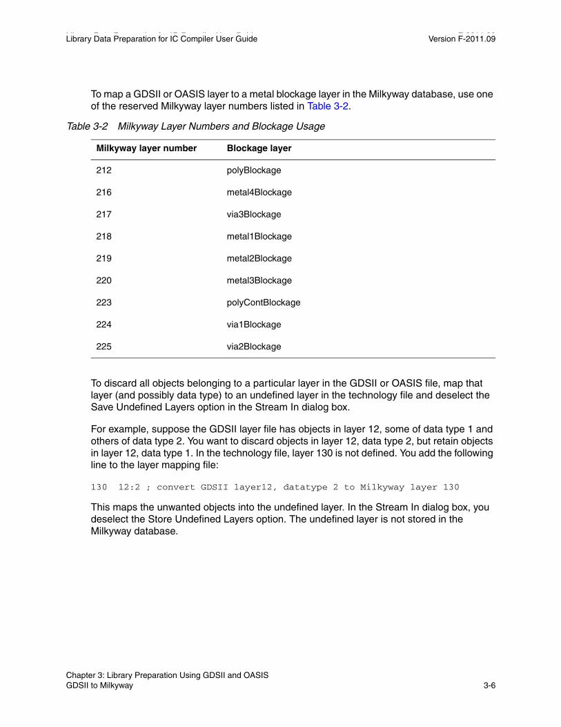
To map a GDSII or OASIS layer to a metal blockage layer in the Milkyway database, use one of the reserved Milkyway layer numbers listed in Table 3-2.
Table 3-2 Milkyway Layer Numbers and Blockage Usage
Milkyway layer number Blockage layer
212 polyBlockage
216 metal4Blockage
217 via3Blockage
218 metal1Blockage
219 metal2Blockage
220 metal3Blockage
223 polyContBlockage
224 via1Blockage
225 via2Blockage
To discard all objects belonging to a particular layer in the GDSII or OASIS file, map that layer (and possibly data type) to an undefined layer in the technology file and deselect the Save Undefined Layers option in the Stream In dialog box.
For example, suppose the GDSII layer file has objects in layer 12, some of data type 1 and others of data type 2. You want to discard objects in layer 12, data type 2, but retain objects in layer 12, data type 1. In the technology file, layer 130 is not defined. You add the following line to the layer mapping file:
130 12:2 ; convert GDSII layer12, datatype 2 to Milkyway layer 130
This maps the unwanted objects into the undefined layer. In the Stream In dialog box, you deselect the Store Undefined Layers option. The undefined layer is not stored in the Milkyway database.
Chapter 3: Library Preparation Using GDSII and OASIS GDSII to Milkyway 3-6
Library Data Preparation for IC Compiler User Guide Version F-2011.09
Milkyway to GDSII
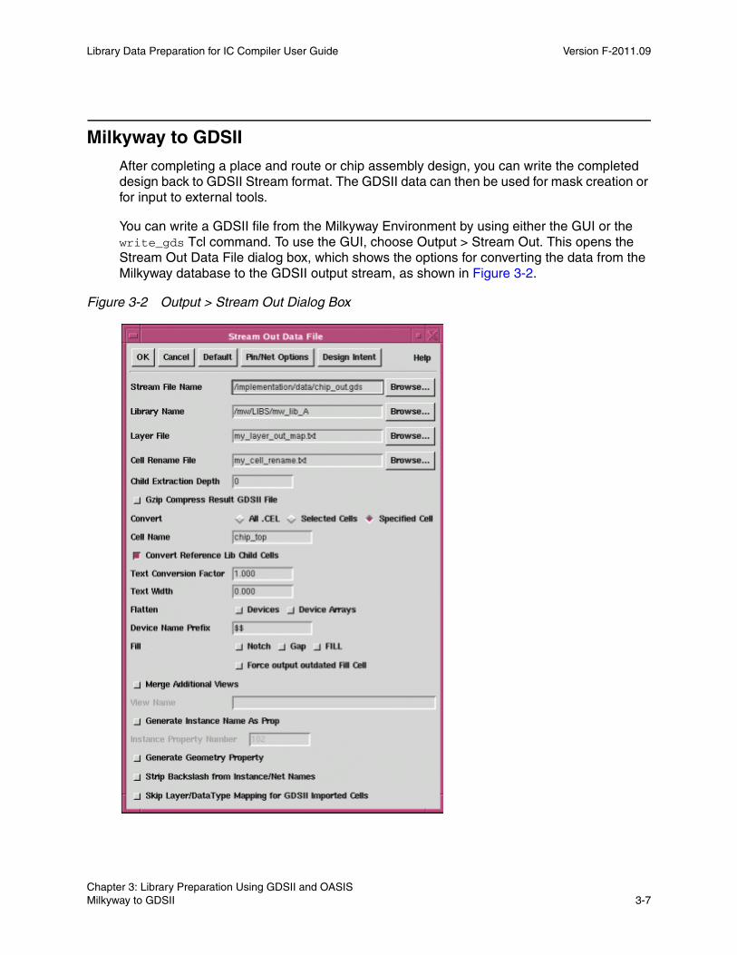
After completing a place and route or chip assembly design, you can write the completed design back to GDSII Stream format. The GDSII data can then be used for mask creation or for input to external tools.
You can write a GDSII file from the Milkyway Environment by using either the GUI or the write_gds Tcl command. To use the GUI, choose Output > Stream Out. This opens the Stream Out Data File dialog box, which shows the options for converting the data from the Milkyway database to the GDSII output stream, as shown in Figure 3-2.
Figure 3-2 Output > Stream Out Dialog Box
Chapter 3: Library Preparation Using GDSII and OASIS Milkyway to GDSII 3-7Chapter 3: Library Preparation Using GDSII and OASIS Milkyway to GDSII 3-7
Library Data Preparation for IC Compiler User Guide F-2011.09Library Data Preparation for IC Compiler User Guide Version F-2011.09
You must at least specify the Stream File Name, which is the name of the GDSII file being written, and the Library Name, which is the name of the Milkyway library containing the cell data to be written. You can convert all cells, the selected cells, or a specified cell in the Milkyway library.
You might also want to specify a stream-out layer mapping file, which identifies the corresponding layer names in the Milkyway and GDSII formats. If this file is not provided, the layer names defined in the Milkyway database are retained in the written GDSII stream. The file format is different from that of the layer mapping file used for GDSII stream-in conversion. For information about the stream-out file format, see “Layer Mapping File: Milkyway to GDSII or OASIS” on page 3-9.
The dialog box options let you specify many options: which cells in the Milkyway library to write, cell renaming, hierarchical extraction depth, hierarchical flattening, the handling of text objects, notch and gap filling, and several other options. Two buttons at the top, Pin/Net Options and Design Intent, open dialog boxes for setting additional options. For a detailed explanation of each option, see the Milkyway Environment online help for the Scheme command auStreamOut.
After you set the dialog box options, click OK. The Milkyway Environment tool translates the specified cells from Milkyway format to GDSII format and writes out the GDSII file.
Instead of using the GUI, you can use the equivalent Tcl command in the Milkyway Environment, write_gds. For details, see the man page for the write_gds command.
In IC Compiler, you can write GDSII data with the write_stream command. For details, see “Reading and Writing GDSII and OASIS in IC Compiler” on page 7-15.
Objects in Milkyway That Can Be Streamed OutOnly physical information can be streamed out from the Milkyway database to the GDSII stream file. Table 3-3 lists the types of Milkyway objects that can be streamed out and the resulting object types in the GDSII output stream.
Table 3-3 Stream Out Objects in Milkyway
Milkyway object GDSII output stream object
CellInstance SREF (structure reference element)
CellInstArray AREF (array reference element)
Contact SREF or boundary element
ContactArray SREF or boundary element
Chapter 3: Library Preparation Using GDSII and OASIS Milkyway to GDSII 3-8

Library Data Preparation for IC Compiler User Guide Version F-2011.09
If you choose the Flatten Devices or Device Arrays option in the Cell Output > Stream Out dialog box, each contact or contact array is converted into several GDSII boundary elements. By default, Milkyway outputs each device or device array as a structure reference element (SREF) with an optional device name prefix if specified in the dialog box.
Because the GDSII format contains only layout information, the Milkyway Environment tool cannot stream out connectivity information or place-and-route objects such as ports, nets, port instances, regions, and cell rows. Extension type objects, such as group, property, and attached file, also cannot be streamed out.
Layer Mapping File: Milkyway to GDSII or OASISFor the stream-out conversion process, specify the desired object-to-layer mapping in the layer mapping file. Specify the file name in the Output > Stream Out dialog box, in the write_gds or write_oasis command in the Milkyway Environment, or in the set_write_stream_options command in IC Compiler.
Each line in the layer mapping file shows a Milkyway object type, Milkyway layer, and resulting GDSII or OASIS layer in the output stream. This is the general syntax:
MilkywayObjType[MilkywayNetType][PinCode] MilkywayLayer[:MilkywayDataType] GDSIILayer [GDSIIDataType]
HorizontalWire Path
Path Path
Pin Boundary element
Polygon Boundary element
Rectangle Boundary element
Text Text
VerticalWire Path
Table 3-3 Stream Out Objects in Milkyway (Continued)
Milkyway object GDSII output stream object
Chapter 3: Library Preparation Using GDSII and OASIS Milkyway to GDSII 3-9Chapter 3: Library Preparation Using GDSII and OASIS Milkyway to GDSII 3-9
Library Data Preparation for IC Compiler User Guide F-2011.09Library Data Preparation for IC Compiler User Guide Version F-2011.09
The first character in the line is the code for the type of Milkyway object to be translated. Use A for all, T for text, or D for data. The optional second character specifies the net type, such as S for signal, P for power, or G for ground. An optional third character specifies the pin code. The Milkyway layer is a name or an integer. The GDSII or OASIS layers and data types are integers.
By default, net text and pin text are mapped into the same layer as the associated net or pin. However, you can specify a different layer for net text or pin text in the layer mapping file.
The following example demonstrates the stream-out layer mapping syntax.
T METAL:2 3 5 ; converts text on Milkyway layer ; METAL data Type 2 to GDSII Stream ; layer #3 data type 5 ; Note: If you stream back into ; Milkyway database without using ; the layer map file, this will ; switch your text on layer METAL ; to layer METAL5
TS 16 31 6 ; converts text associated with ; signal nets on Milkyway layer #16 ; to GDSII Stream layer #31 and ; data type 6
TP METAL3 16 ; converts text associated with ; power on Milkyway layer METAL3 ; to GDSII Stream layer #16
TG 28 16 ; converts text associated with ; ground on Milkyway layer #28 ; to GDSII Stream layer #16
D METAL2 45 ; converts data on Milkyway layer ; METAL2 to GDSII Stream layer #45
DS 45:2 18 5 ; converts data associated with ; signal nets on Milkyway layer #45 ; data Type 2 to GDSII Stream layer #18 ; data Type 5
A METAL6 3 4 ; converts text and data on ; Milkyway Layer METAL6 to GDSII ; Stream layer #3 and datatype 4
A METAL4 - ; minus sign (hyphen) prevents transfer of all ; text and data on Milkyway layer METAL4
Chapter 3: Library Preparation Using GDSII and OASIS Milkyway to GDSII 3-10
Library Data Preparation for IC Compiler User Guide Version F-2011.09
You can add a comment to the file by inserting a semicolon. Text is ignored from the semicolon to the end of the line. A hyphen character in the GDSII or OASIS layer position prevents the transfer of all text and data in the specified Milkyway object and layer.
Table 3-4 describes the items used in each line of the layer mapping file.
Table 3-4 GDSII Stream-Out Layer Mapping File Syntax
Variable Description
MilkywayObjType The code for the type of object in the data to be translated:
A for all types
T for text
D for data
MilkywayNetType The code for the net type of the object in the data to be translated:
S for signal
P for power
G for ground
C for clock
U for Up conduction layer (upper layer in a via). Example: metal2 in an m1/m2 via
D for Down conduction layer (lower layer in a via). Example: metal1 in an m1/m2 via
X for power and ground wires or contacts with a “signal” or “tie-off” routing type.
A for all net types.
Note that U and D are used only for via and flattened via objects. They override any other net type set for the layer when the layer is in a via.
If MilkywayNetType is omitted, the Milkyway tool maps all Milkyway data of the specified object type to the specified GDSII or OASIS layer.
If MilkywayNetType is included, the Milkyway tool examines every object of the object type to determine its net type and maps it to the layer you specify. If an object has no net or a net has no type, Milkyway assumes that it is a signal net.
If a layer file contains contradictory lines, the last line overrides any previous line. For example, if an earlier line of a layer file specifies mapping for a particular object or net type and a later line specifies mapping for the same object type but no net type, the Milkyway tool translates all data of the specified object type as defined by the later line.
Chapter 3: Library Preparation Using GDSII and OASIS Milkyway to GDSII 3-11Chapter 3: Library Preparation Using GDSII and OASIS Milkyway to GDSII 3-11
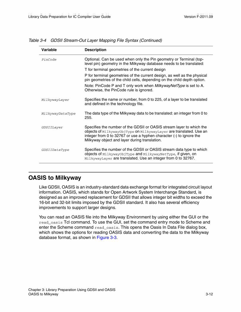
Library Data Preparation for IC Compiler User Guide F-2011.09Library Data Preparation for IC Compiler User Guide Version F-2011.09
OASIS to Milkyway
Like GDSII, OASIS is an industry-standard data exchange format for integrated circuit layout information. OASIS, which stands for Open Artwork System Interchange Standard, is designed as an improved replacement for GDSII that allows integer bit widths to exceed the 16-bit and 32-bit limits imposed by the GDSII standard. It also has several efficiency improvements to support larger designs.
You can read an OASIS file into the Milkyway Environment by using either the GUI or the read_oasis Tcl command. To use the GUI, set the command entry mode to Scheme and enter the Scheme command read_oasis. This opens the Oasis In Data File dialog box, which shows the options for reading OASIS data and converting the data to the Milkyway database format, as shown in Figure 3-3.
PinCode Optional. Can be used when only the Pin geometry or Terminal (top-level pin) geometry in the Milkyway database needs to be translated:
T for terminal geometries of the current design
P for terminal geometries of the current design, as well as the physical pin geometries of the child cells, depending on the child depth option.
Note: PinCode P and T only work when MilkywayNetType is set to A. Otherwise, the PinCode rule is ignored.
MilkywayLayer Specifies the name or number, from 0 to 225, of a layer to be translated and defined in the technology file.
MilkywayDataType The data type of the Milkyway data to be translated: an integer from 0 to 255.
GDSIILayer Specifies the number of the GDSII or OASIS stream layer to which the objects of MilkywayObjType on MilkywayLayer are translated. Use an integer from 0 to 32767 or use a hyphen character (-) to ignore the Milkyway object and layer during translation.
GDSIIDataType Specifies the number of the GDSII or OASIS stream data type to which objects of MilkywayObjType and MilkywayNetType, if given, on MilkywayLayer are translated. Use an integer from 0 to 32767.
Table 3-4 GDSII Stream-Out Layer Mapping File Syntax (Continued)
Variable Description
Chapter 3: Library Preparation Using GDSII and OASIS OASIS to Milkyway 3-12
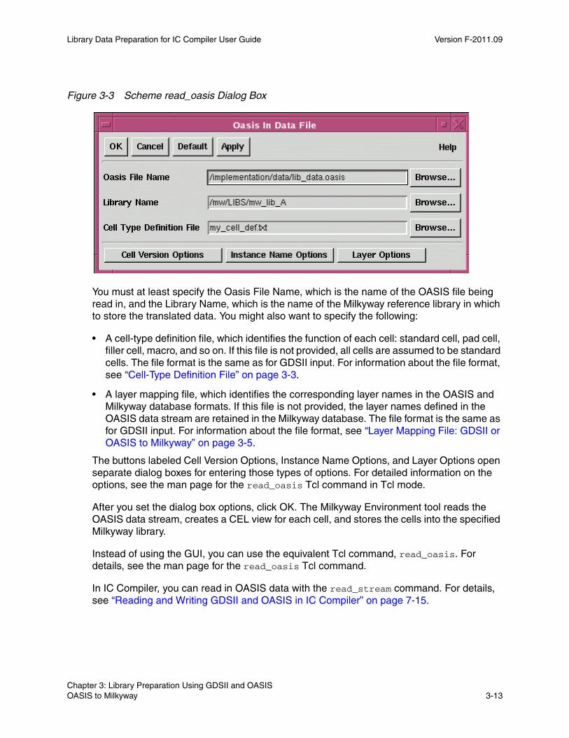
Library Data Preparation for IC Compiler User Guide Version F-2011.09
Figure 3-3 Scheme read_oasis Dialog Box
You must at least specify the Oasis File Name, which is the name of the OASIS file being read in, and the Library Name, which is the name of the Milkyway reference library in which to store the translated data. You might also want to specify the following:
• A cell-type definition file, which identifies the function of each cell: standard cell, pad cell, filler cell, macro, and so on. If this file is not provided, all cells are assumed to be standard cells. The file format is the same as for GDSII input. For information about the file format, see “Cell-Type Definition File” on page 3-3.
• A layer mapping file, which identifies the corresponding layer names in the OASIS and Milkyway database formats. If this file is not provided, the layer names defined in the OASIS data stream are retained in the Milkyway database. The file format is the same as for GDSII input. For information about the file format, see “Layer Mapping File: GDSII or OASIS to Milkyway” on page 3-5.
The buttons labeled Cell Version Options, Instance Name Options, and Layer Options open separate dialog boxes for entering those types of options. For detailed information on the options, see the man page for the read_oasis Tcl command in Tcl mode.
After you set the dialog box options, click OK. The Milkyway Environment tool reads the OASIS data stream, creates a CEL view for each cell, and stores the cells into the specified Milkyway library.
Instead of using the GUI, you can use the equivalent Tcl command, read_oasis. For details, see the man page for the read_oasis Tcl command.
In IC Compiler, you can read in OASIS data with the read_stream command. For details, see “Reading and Writing GDSII and OASIS in IC Compiler” on page 7-15.
Chapter 3: Library Preparation Using GDSII and OASIS OASIS to Milkyway 3-13Chapter 3: Library Preparation Using GDSII and OASIS OASIS to Milkyway 3-13

Library Data Preparation for IC Compiler User Guide F-2011.09Library Data Preparation for IC Compiler User Guide Version F-2011.09
Milkyway to OASIS
After completing placement and routing or a chip assembly, you can write the completed design to OASIS format. The OASIS data can then be used for mask creation or for input to external tools.
You can write an OASIS file from the Milkyway Environment by using either the GUI or the write_oasis Tcl command. To use the GUI, set the command entry mode to Scheme and enter the Scheme command write_oasis. This opens the Oasis Out Data File dialog box, which shows the options for converting the data from the Milkyway database to the OASIS output stream, as shown in Figure 3-4.
Figure 3-4 Scheme write_oasis Dialog Box
You must at least specify the Oasis File Name, which is the name of file being written, and the Library Name, which is the name of the Milkyway library containing the cell data to be written.
You might also want to specify a stream-out layer mapping file, which identifies the corresponding layer names in the Milkyway and OASIS database formats. If this file is not provided, the layer names defined in the Milkyway database are retained in the written
Chapter 3: Library Preparation Using GDSII and OASIS Milkyway to OASIS 3-14

Library Data Preparation for IC Compiler User Guide Version F-2011.09
OASIS stream. The file format is the same as that used for GDSII stream-out conversion. For information about the stream-out file format, see “Layer Mapping File: Milkyway to GDSII or OASIS” on page 3-9.
The dialog box options let you specify several options, including the cells in the Milkyway library to write, the hierarchical extraction depth, and the output file compression. Four buttons at the bottom, Net/Pin Options, Fill Options, Contact Options, and Special Options, open dialog boxes for setting additional options. For a detailed explanation of each option, see the man page for the Tcl command write_oasis in Tcl mode.
After you set the dialog box options, click OK. The Milkyway Environment tool translates the specified cells from Milkyway format to OASIS format and writes out the OASIS file.
Instead of using the GUI, you can use the equivalent Tcl command, write_oasis. For details, see the man page for the write_oasis command.
In IC Compiler, you can write OASIS data with the write_stream command. For details, see “Reading and Writing GDSII and OASIS in IC Compiler” on page 7-15.
The types of Milkyway objects that can be streamed out are the same as for exporting data in GDSII format. For details, see “Objects in Milkyway That Can Be Streamed Out” on page 3-8.
Chapter 3: Library Preparation Using GDSII and OASIS Milkyway to OASIS 3-15Chapter 3: Library Preparation Using GDSII and OASIS Milkyway to OASIS 3-15
Library Data Preparation for IC Compiler User Guide F-2011.09Library Data Preparation for IC Compiler User Guide Version F-2011.09
Chapter 3: Library Preparation Using GDSII and OASIS Milkyway to OASIS 3-16

4Library Preparation Using LEF/DEF 4
To prepare a Milkyway reference library from cell data in LEF format, you import the data into the Milkyway Environment and translate that data into the Milkyway database. You can also import and export design data in DEF format. Importing and exporting LEF and DEF data are described in the following sections:
• LEF and DEF Data
• LEF to Milkyway
• Milkyway to LEF
• DEF Input and Output
4-1
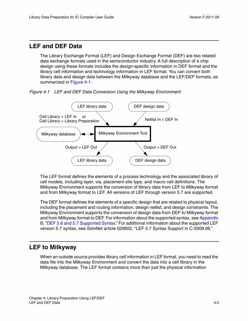
Library Data Preparation for IC Compiler User Guide F-2011.09Library Data Preparation for IC Compiler User Guide Version F-2011.09
LEF and DEF Data
The Library Exchange Format (LEF) and Design Exchange Format (DEF) are two related data exchange formats used in the semiconductor industry. A full description of a chip design using these formats includes the design-specific information in DEF format and the library cell information and technology information in LEF format. You can convert both library data and design data between the Milkyway database and the LEF/DEF formats, as summarized in Figure 4-1.
Figure 4-1 LEF and DEF Data Conversion Using the Milkyway Environment
LEF library data
DEF design data
Milkyway database Milkyway Environment Tool
Cell Library > LEF In orCell Library > Library Preparation
Output > LEF Out Output > DEF Out
Netlist In > DEF In
LEF library data
DEF design data
The LEF format defines the elements of a process technology and the associated library of cell models, including layer, via, placement site type, and macro cell definitions. The Milkyway Environment supports the conversion of library data from LEF to Milkyway format and from Milkyway format to LEF. All versions of LEF through version 5.7 are supported.
The DEF format defines the elements of a specific design that are related to physical layout, including the placement and routing information, design netlist, and design constraints. The Milkyway Environment supports the conversion of design data from DEF to Milkyway format and from Milkyway format to DEF. For information about the supported syntax, see Appendix B, “DEF 5.6 and 5.7 Supported Syntax.” For additional information about the supported LEF version 5.7 syntax, see SolvNet article 029602, “LEF 5.7 Syntax Support in C-2009.06.”
LEF to Milkyway
When an outside source provides library cell information in LEF format, you need to read the data file into the Milkyway Environment and convert the data into a cell library in the Milkyway database. The LEF format contains more than just the physical information
Chapter 4: Library Preparation Using LEF/DEF LEF and DEF Data 4-2
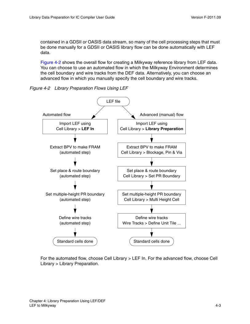
Library Data Preparation for IC Compiler User Guide Version F-2011.09
contained in a GDSII or OASIS data stream, so many of the cell processing steps that must be done manually for a GDSII or OASIS library flow can be done automatically with LEF data.
Figure 4-2 shows the overall flow for creating a Milkyway reference library from LEF data. You can choose to use an automated flow in which the Milkyway Environment determines the cell boundary and wire tracks from the DEF data. Alternatively, you can choose an advanced flow in which you manually specify the cell boundary and wire tracks.
Figure 4-2 Library Preparation Flows Using LEF
Extract BPV to make FRAMCell Library > Blockage, Pin & Via
Set place & route boundaryCell Library > Set PR Boundary
Set multiple-height PR boundaryCell Library > Multi Height Cell
Define wire tracksWire Tracks > Define Unit Tile ...
Import LEF usingCell Library > LEF In
Standard cells done
LEF file
Advanced (manual) flow
Import LEF usingCell Library > Library Preparation
Automated flow
Extract BPV to make FRAM(automated step)
Set place & route boundary(automated step)
Set multiple-height PR boundary(automated step)
Define wire tracks(automated step)
Standard cells done
For the automated flow, choose Cell Library > LEF In. For the advanced flow, choose Cell Library > Library Preparation.
Chapter 4: Library Preparation Using LEF/DEF LEF to Milkyway 4-3Chapter 4: Library Preparation Using LEF/DEF LEF to Milkyway 4-3

Library Data Preparation for IC Compiler User Guide F-2011.09Library Data Preparation for IC Compiler User Guide Version F-2011.09
In addition to the flows shown in Figure 4-2, you can choose a mixed flow that uses some combination of library and technology information in LEF, GDSII, CLF, PLIB, and TF formats. For this flow, you choose Cell Library > Library Preparation.
Automated LEF Input FlowYou can import LEF data in the automated mode by using either the GUI or the read_lef Tcl command. To use the GUI, choose Cell Library > LEF In. This opens the Read LEF dialog box, as shown in Figure 4-3. The dialog box displays the options for reading DEF data and converting the data to the Milkyway database format.
Figure 4-3 Cell Library > LEF In Dialog Box
Specify the name of the Milkyway library in which to store the converted data, the names of the LEF technology files containing the technology information, and the names of the LEF files containing the physical cell data.
Chapter 4: Library Preparation Using LEF/DEF LEF to Milkyway 4-4
Library Data Preparation for IC Compiler User Guide Version F-2011.09
If the specified Milkyway library does not already exist, the tool creates a new Milkyway reference library based on the LEF information. If the Milkyway library already exists, the tool performs an incremental update, which adds new cells to the existing library. During an incremental LEF import, all LEF files must have the same version number if you are using LEF version 5.4 or later.
LEF files can contain technology information, physical cell information, or both. The information you need might be contained in a single LEF file or in multiple LEF files. Enter the name or names of the files in the Tech LEF Files and Cell LEF Files text boxes. Multiple file names in a text box must be separated by space characters.
From the files listed in the Tech LEF Files text box, only the technology information is used, not the cell-level information. Similarly, from the files listed in the Cell LEF Files text box, only the cell-level information is used, not the technology information. If a file contains both technology information and cell information that you need, be sure to enter that file name into both text boxes.
You might also want to specify a layer mapping file, which identifies the corresponding layer names in the DEF and Milkyway database formats. If this file is not provided, the first layer in DEF is mapped to layer 1 in Milkyway, the second layer is mapped to layer 2, and so on. For information about the file format, see “LEF to Milkyway Layer Mapping File” on page 4-8.
The dialog box also offers the following options:
• Overwrite Existing Tech – Use this option to overwrite, rather than add to, the existing technology information in the Milkyway library.
• Ignore Cell Geometries – Use this option to ignore physical cell information, for example, when you want to import only the technology information in DEF format and you plan to get the cell information in GDSII format.
• Advanced Library Prep Mode – Use this option to invoke the advanced (manual) flow after the DEF files have been imported. For information about this flow, see “Advanced LEF Input Flow” on page 4-6.
• Same Name Cell Resolution – Specify how to handle the an imported cell that has the same name as an existing cell in the target Milkyway library.
After you set the dialog box options, click OK. The Milkyway Environment tool reads the DEF, converts the technology information into Milkyway format, creates a CEL view for each cell, and stores the cells into the specified Milkyway library. It also determines the standard-cell place-and-route boundaries, multiple-height place-and-route boundaries, and wire tracks of the cells. If the automated flow does not produce the desired results, start again and choose the advanced flow.
Chapter 4: Library Preparation Using LEF/DEF LEF to Milkyway 4-5Chapter 4: Library Preparation Using LEF/DEF LEF to Milkyway 4-5
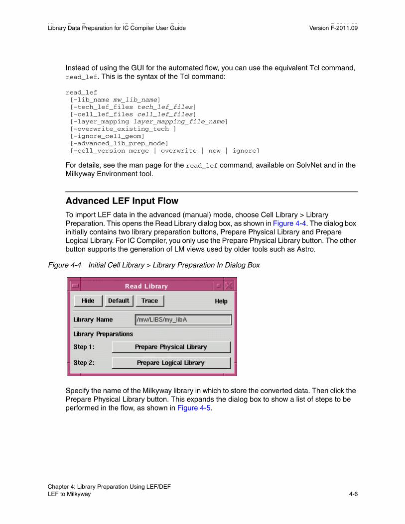
Library Data Preparation for IC Compiler User Guide F-2011.09Library Data Preparation for IC Compiler User Guide Version F-2011.09
Instead of using the GUI for the automated flow, you can use the equivalent Tcl command, read_lef. This is the syntax of the Tcl command:
read_lef [-lib_name mw_lib_name] [-tech_lef_files tech_lef_files] [-cell_lef_files cell_lef_files] [-layer_mapping layer_mapping_file_name] [-overwrite_existing_tech ] [-ignore_cell_geom] [-advanced_lib_prep_mode] [-cell_version merge | overwrite | new | ignore]
For details, see the man page for the read_lef command, available on SolvNet and in the Milkyway Environment tool.
Advanced LEF Input FlowTo import LEF data in the advanced (manual) mode, choose Cell Library > Library Preparation. This opens the Read Library dialog box, as shown in Figure 4-4. The dialog box initially contains two library preparation buttons, Prepare Physical Library and Prepare Logical Library. For IC Compiler, you only use the Prepare Physical Library button. The other button supports the generation of LM views used by older tools such as Astro.
Figure 4-4 Initial Cell Library > Library Preparation In Dialog Box
Specify the name of the Milkyway library in which to store the converted data. Then click the Prepare Physical Library button. This expands the dialog box to show a list of steps to be performed in the flow, as shown in Figure 4-5.
Chapter 4: Library Preparation Using LEF/DEF LEF to Milkyway 4-6

Library Data Preparation for IC Compiler User Guide Version F-2011.09
Figure 4-5 Expanded Cell Library > Library Preparation In Dialog Box
The Physical Library Check: Check Library button opens a separate dialog box that lets you perform a check of a physical library in Milkyway format. Library checking is described in Chapter 6, “Library Checking.”
The Physical Input Format option button specifies the type or types of data files you are importing into the Milkyway format. If you are importing only LEF files, make sure the button is set to LEF as shown in the foregoing figure.
With the Physical Input Format button set to LEF, the list of steps shown below the button reflect the flow for importing data from LEF files. To perform the steps in the flow, click the buttons one at a time, starting from the first step, Import LEF. As each step is completed, a check mark appears in the small box to the right of the corresponding button.
Chapter 4: Library Preparation Using LEF/DEF LEF to Milkyway 4-7Chapter 4: Library Preparation Using LEF/DEF LEF to Milkyway 4-7
Library Data Preparation for IC Compiler User Guide F-2011.09Library Data Preparation for IC Compiler User Guide Version F-2011.09
These are the steps in the LEF-only input flow:
1. Import LEF – Opens the Read LEF dialog box described in the previous section, “Automated LEF Input Flow” on page 4-4.
2. Extract BPV – Opens the Extract Blockage dialog box. See “Extract Blockage Options” on page 5-7.
3. Set PR Boundary – Opens the Set PR Boundary dialog box. See “Set the Place-and-Route Boundary” on page 5-19.
4. Set Property for Multiple Height Cells – Opens the Set Multiple Height PR Boundary dialog box. See “Set the Multiple-Height Boundary” on page 5-23.
5. Define Wire Track – Opens the Define Wire Track dialog box. See “Define the Unit Tile Wire Tracks” on page 5-23.
6. Check Wire Track – Opens the Check Wire Track dialog box. See “Check the Wire Tracks” on page 5-27.
7. Create PDB – Skip this step for Milkyway library usage in IC Compiler. If run, this step creates an LM view, which is used only in older tools such as Astro.
LEF to Milkyway Layer Mapping FileA layer mapping file specifies the Milkyway layer resulting from each LEF layer. If no layer mapping file is used, Milkyway follows its internal default order, with the first layer in LEF mapping to layer 1 in Milkyway, the second layer in LEF mapping to layer 2 in Milkyway, and so on.
You can use a Perl script to create a layer mapping file. The script is available in the SolvNet article “Using the lef_layer_tf_number_mapper.pl script.” This is the usage syntax:
lef_layer_tf_number_mapper.pl tech_file_name lef_file_name
For example, if gold_x.tf and test_y.lef are the .tf technology file and the LEF file, respectively, run this script at the operating system prompt:
% lef_layer_tf_number_mapper.pl gold_x.tf test_y.lef
This generates a map file called test_y_gold_x.map and a log file called test_y_gold_x.log.
The following is an example of a layer mapping file:
LEF layer name Milkyway Layer numberMETAL1 10VIA12 11METAL2 20
Chapter 4: Library Preparation Using LEF/DEF LEF to Milkyway 4-8
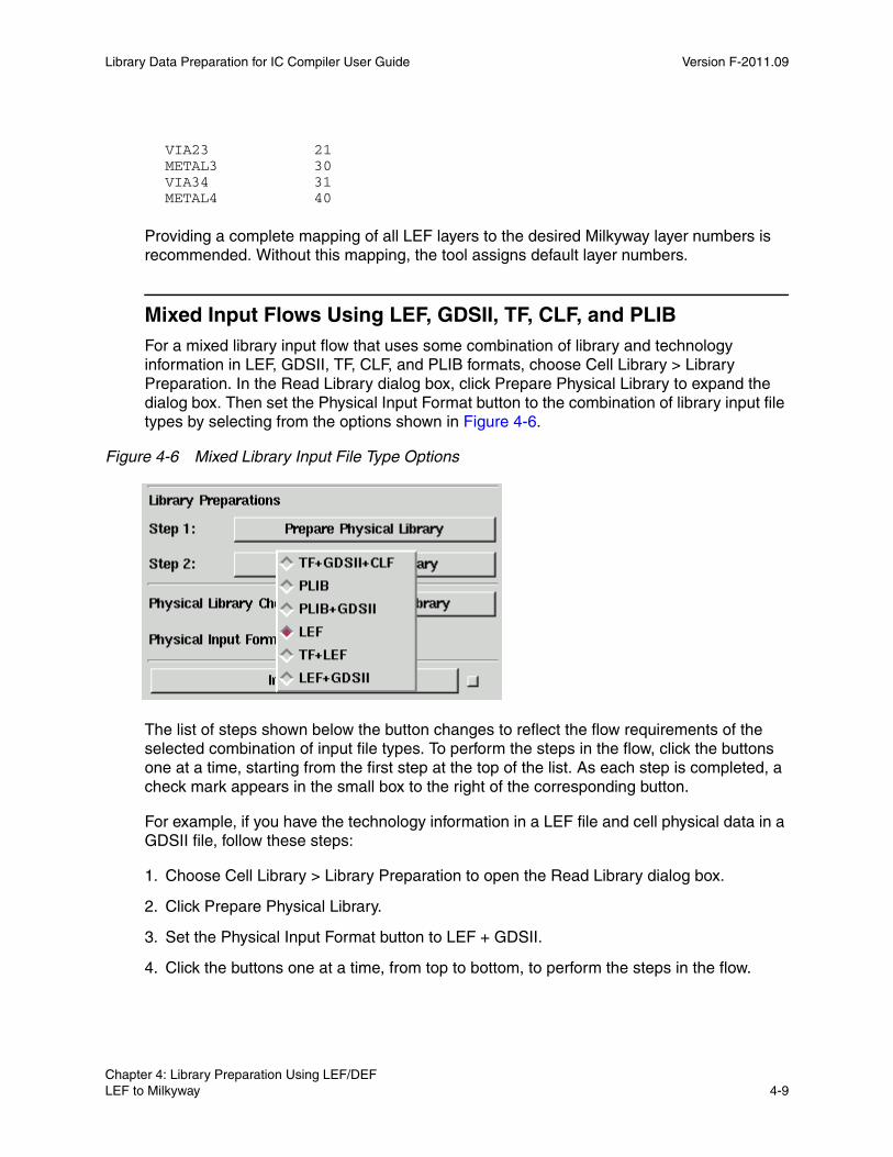
Library Data Preparation for IC Compiler User Guide Version F-2011.09
VIA23 21METAL3 30VIA34 31METAL4 40
Providing a complete mapping of all LEF layers to the desired Milkyway layer numbers is recommended. Without this mapping, the tool assigns default layer numbers.
Mixed Input Flows Using LEF, GDSII, TF, CLF, and PLIBFor a mixed library input flow that uses some combination of library and technology information in LEF, GDSII, TF, CLF, and PLIB formats, choose Cell Library > Library Preparation. In the Read Library dialog box, click Prepare Physical Library to expand the dialog box. Then set the Physical Input Format button to the combination of library input file types by selecting from the options shown in Figure 4-6.
Figure 4-6 Mixed Library Input File Type Options
The list of steps shown below the button changes to reflect the flow requirements of the selected combination of input file types. To perform the steps in the flow, click the buttons one at a time, starting from the first step at the top of the list. As each step is completed, a check mark appears in the small box to the right of the corresponding button.
For example, if you have the technology information in a LEF file and cell physical data in a GDSII file, follow these steps:
1. Choose Cell Library > Library Preparation to open the Read Library dialog box.
2. Click Prepare Physical Library.
3. Set the Physical Input Format button to LEF + GDSII.
4. Click the buttons one at a time, from top to bottom, to perform the steps in the flow.
Chapter 4: Library Preparation Using LEF/DEF LEF to Milkyway 4-9Chapter 4: Library Preparation Using LEF/DEF LEF to Milkyway 4-9

Library Data Preparation for IC Compiler User Guide F-2011.09Library Data Preparation for IC Compiler User Guide Version F-2011.09
If you need information about using a dialog box, click the Help button in the dialog box. This opens an online help window for that dialog box.
Milkyway to LEF
You can export a Milkyway library to LEF format for use by external tools. The LEF format defines the elements of an IC process technology and associated library of cell models and contains library information for a class of designs. This library information includes layer, via, placement site type, and macro cell definitions.
You can write a LEF file from the Milkyway Environment by using either the GUI or the write_lef Tcl command. To use the GUI, choose Output > LEF out. This opens the Write LEF dialog box, which shows the options for converting the data from the Milkyway database to LEF format, as shown in Figure 4-7.
Figure 4-7 Output > LEF Out Dialog Box
Chapter 4: Library Preparation Using LEF/DEF Milkyway to LEF 4-10
Library Data Preparation for IC Compiler User Guide Version F-2011.09
You must at least specify the name of the Milkyway library to be converted, the name of the cell in the library to be converted, and the name of LEF file to be written. If the LEF file already exists, it is overwritten. Use the other dialog box options to specify the LEF version number and the types of technology and cell information to be written. For detailed information about these options, click the Help button in the dialog box or see the man page for the Tcl command write_lef in Tcl mode.
After you set the dialog box options, click OK. The Milkyway Environment tool translates the specified cells from Milkyway format to LEF format and writes out the LEF file.
Instead of using the GUI, you can use the equivalent Tcl command, write_lef. The Tcl command supports LEF version 5.7, which the Output > LEF Out dialog box does not support. This is the Tcl command syntax:
write_lef [-lib_name lib_name] [-output_cell cell_name] [-output_version 5.3 | 5.4 | 5.5 | 5.6 | 5.7] [-ignore_tech_info] [-ignore_tech_signal_em] [-ignore_tech_antenna_rule] [-ignore_tech_other_info] [-ignore_cell_info] [-ignore_cell_geom] [-output_via_blockages] [-output_metal_blockages] [-output_route_guides] lef_file_name
For details, see the man page for the write_lef command.
DEF Input and Output
The Design Exchange Format (DEF) defines the elements of an IC design that are relevant to the physical layout, including the placement and routing information, design netlist, and design constraints. It contains the design-specific information for a circuit and is a representation of the design at any point during the layout process.
You can read DEF files into a Milkyway library and write DEF files from a Milkyway library. DEF versions 5.3 through 5.7 are supported.
Importing DEF FilesThe DEF format defines the elements of a specific design that are related to physical layout, including the placement and routing information, design netlist, and design constraints.
Chapter 4: Library Preparation Using LEF/DEF DEF Input and Output 4-11Chapter 4: Library Preparation Using LEF/DEF DEF Input and Output 4-11
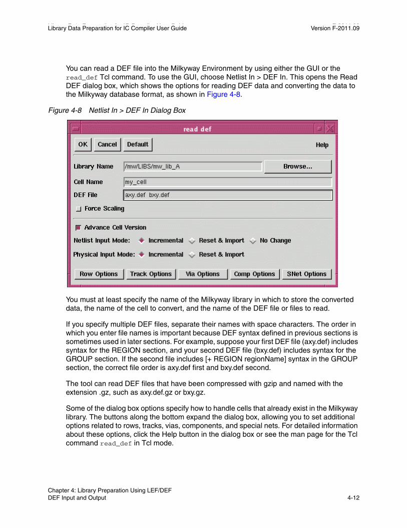
Library Data Preparation for IC Compiler User Guide F-2011.09Library Data Preparation for IC Compiler User Guide Version F-2011.09
You can read a DEF file into the Milkyway Environment by using either the GUI or the read_def Tcl command. To use the GUI, choose Netlist In > DEF In. This opens the Read DEF dialog box, which shows the options for reading DEF data and converting the data to the Milkyway database format, as shown in Figure 4-8.
Figure 4-8 Netlist In > DEF In Dialog Box
You must at least specify the name of the Milkyway library in which to store the converted data, the name of the cell to convert, and the name of the DEF file or files to read.
If you specify multiple DEF files, separate their names with space characters. The order in which you enter file names is important because DEF syntax defined in previous sections is sometimes used in later sections. For example, suppose your first DEF file (axy.def) includes syntax for the REGION section, and your second DEF file (bxy.def) includes syntax for the GROUP section. If the second file includes [+ REGION regionName] syntax in the GROUP section, the correct file order is axy.def first and bxy.def second.
The tool can read DEF files that have been compressed with gzip and named with the extension .gz, such as axy.def.gz or bxy.gz.
Some of the dialog box options specify how to handle cells that already exist in the Milkyway library. The buttons along the bottom expand the dialog box, allowing you to set additional options related to rows, tracks, vias, components, and special nets. For detailed information about these options, click the Help button in the dialog box or see the man page for the Tcl command read_def in Tcl mode.
Chapter 4: Library Preparation Using LEF/DEF DEF Input and Output 4-12
Library Data Preparation for IC Compiler User Guide Version F-2011.09
After you set the dialog box options, click OK. The Milkyway Environment tool reads the DEF files, converts the data into a CEL view, and stores the data into the specified Milkyway library. The conversion process checks the syntax used in the DEF file. Any issues found are reported with information messages, warnings, and error messages, depending on the severity of the violation.
Instead of using the GUI, you can use the equivalent Tcl command, read_def. The Tcl command offers a few options that are not available in the GUI dialog box. These options are related to the processing of text in the GDSII data stream. This is the command syntax:
read_def [-lib library_name] [-design design_name] [-enforce_scaling] [-allow_physical] [-no_incremental] [-advance_cell_version] [-netl_phys {incr_incr | incr_rimport| rimport_rimport | nochange_incr | nochange_rimport}] [-site site_definition_file_name] [-verbose] [-core core_site_name] [-turn_via_to_inst] [-inexactly_matched_via_to_inst] [-skip_signal_nets] [-lef lef_file_name] [-blackbox blackbox_ref_file_name] [-blackbox_size blackbox_size] [-snet_no_shape_as_user_enter] [-snet_no_shape_as_detail_route] def_file_names
For details, see the man page for the read_def command, available on SolvNet and in the Milkyway Environment tool.
Exporting DEF FilesYou can write a DEF file from the Milkyway Environment by using either the GUI or the write_def Tcl command. To use the GUI, choose Output > DEF Out. This opens the Write DEF dialog box, which shows the options for converting the data from the Milkyway database format and writing the DEF file, as shown in Figure 4-9.
Chapter 4: Library Preparation Using LEF/DEF DEF Input and Output 4-13Chapter 4: Library Preparation Using LEF/DEF DEF Input and Output 4-13
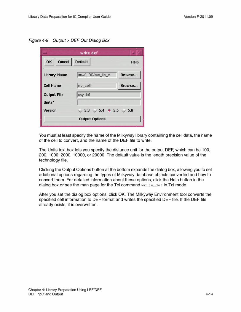
Library Data Preparation for IC Compiler User Guide F-2011.09Library Data Preparation for IC Compiler User Guide Version F-2011.09
Figure 4-9 Output > DEF Out Dialog Box
You must at least specify the name of the Milkyway library containing the cell data, the name of the cell to convert, and the name of the DEF file to write.
The Units text box lets you specify the distance unit for the output DEF, which can be 100, 200, 1000, 2000, 10000, or 20000. The default value is the length precision value of the technology file.
Clicking the Output Options button at the bottom expands the dialog box, allowing you to set additional options regarding the types of Milkyway database objects converted and how to convert them. For detailed information about these options, click the Help button in the dialog box or see the man page for the Tcl command write_def in Tcl mode.
After you set the dialog box options, click OK. The Milkyway Environment tool converts the specified cell information to DEF format and writes the specified DEF file. If the DEF file already exists, it is overwritten.
Chapter 4: Library Preparation Using LEF/DEF DEF Input and Output 4-14
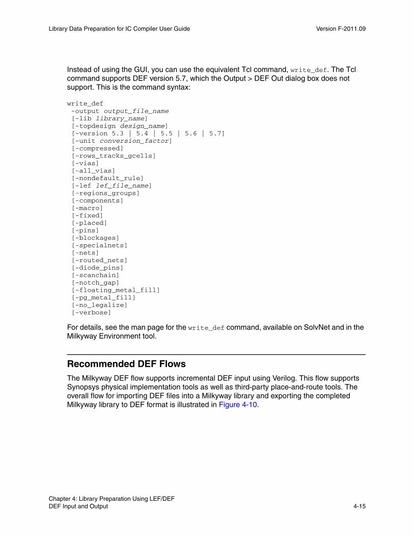
Library Data Preparation for IC Compiler User Guide Version F-2011.09
Instead of using the GUI, you can use the equivalent Tcl command, write_def. The Tcl command supports DEF version 5.7, which the Output > DEF Out dialog box does not support. This is the command syntax:
write_def -output output_file_name [-lib library_name] [-topdesign design_name] [-version 5.3 | 5.4 | 5.5 | 5.6 | 5.7] [-unit conversion_factor] [-compressed] [-rows_tracks_gcells] [-vias] [-all_vias] [-nondefault_rule] [-lef lef_file_name] [-regions_groups] [-components] [-macro] [-fixed] [-placed] [-pins] [-blockages] [-specialnets] [-nets] [-routed_nets] [-diode_pins] [-scanchain] [-notch_gap] [-floating_metal_fill] [-pg_metal_fill] [-no_legalize] [-verbose]
For details, see the man page for the write_def command, available on SolvNet and in the Milkyway Environment tool.
Recommended DEF FlowsThe Milkyway DEF flow supports incremental DEF input using Verilog. This flow supports Synopsys physical implementation tools as well as third-party place-and-route tools. The overall flow for importing DEF files into a Milkyway library and exporting the completed Milkyway library to DEF format is illustrated in Figure 4-10.
Chapter 4: Library Preparation Using LEF/DEF DEF Input and Output 4-15Chapter 4: Library Preparation Using LEF/DEF DEF Input and Output 4-15

Library Data Preparation for IC Compiler User Guide F-2011.09Library Data Preparation for IC Compiler User Guide Version F-2011.09
Figure 4-10 Flow for Importing and Exporting DEF Files
Step 1Create design library
Step 2Add reference libraries
Step 3Check DEF row type
Step 4Check wire track direction
Step 5Import DEF
Step 6Export DEFDEF
This is the procedure for importing and exporting DEF:
1. Create a Milkyway design library from the technology (.tf) file.
2. Add the required reference libraries.
3. Check the input DEF file for the row type.
The name of the site in the design or reference library is “unit.” The row type should match this name. If the row type does not match the site name of the design or reference library (“unit”), the tool does not create rows.
4. Check for the wire track direction.
By default, the wire track direction of all metal layers is horizontal. Therefore, you must tell the tool about the wire track direction of each layer.
During DEF input using the Netlist In > DEF In (Read DEF) dialog box, when the preferred wire track direction for a layer is not initialized, DEF reader attempts to set it according to the wire direction (WireDirection) object unitTile in the main library and reference libraries. If it fails to set, DEF reader generates a warning message.
Chapter 4: Library Preparation Using LEF/DEF DEF Input and Output 4-16
Library Data Preparation for IC Compiler User Guide Version F-2011.09
Next, after you click the Track Options button, enable the Set Layer Preferred Direction option and set the track direction for metal layers M1, M2, M3, and M4. All the metal layers higher than M4 are set to alternating directions with respect to M4.
5. With all the options set as desired, click OK in the Read DEF dialog box to import the DEF file or files into the Milkyway design library.
6. Export the Design information to a DEF file using the Output > DEF Out dialog box.
There are two types of vias in DEF. One type is the set of vias defined in the Milkyway technology file. The other type is the set of vias generated by the implementation tool during design preparation and not defined in the technology file.
For each via referenced in the net section wiring, if a match to any of the Milkyway technology contact codes cannot be found, the via is translated as a Milkyway via cell instance. The vias in the DEF vias section define all generated vias in the design. Therefore, a via cell is created to store all physical information before an effort is made to find the best match to any of the contact codes.
DEF can be read in incrementally, which means that reading DEF files can add more information to the existing cell in the Milkyway database. For example, if you have a placed cell and want to add clock routing on top of this cell using a DEF file, set the Netlist Input Mode and Physical Input Mode options to Incremental in the Read DEF dialog box.
Figure 4-11 shows the incremental DEF flow of reading Verilog followed by DEF.
Chapter 4: Library Preparation Using LEF/DEF DEF Input and Output 4-17Chapter 4: Library Preparation Using LEF/DEF DEF Input and Output 4-17
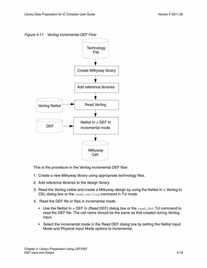
Library Data Preparation for IC Compiler User Guide F-2011.09Library Data Preparation for IC Compiler User Guide Version F-2011.09
Figure 4-11 Verilog Incremental DEF Flow
Technology File
Create Milkyway library
Add reference libraries
Read Verilog
incremental mode
Milkyway Cell
Verilog Netlist
DEFNetlist In > DEF In
This is the procedure in the Verilog incremental DEF flow:
1. Create a new Milkyway library using appropriate technology files.
2. Add reference libraries to the design library.
3. Read the Verilog netlist and create a Milkyway design by using the Netlist In > Verilog to CEL dialog box or the read_verilog command in Tcl mode.
4. Read the DEF file or files in incremental mode.
• Use the Netlist In > DEF In (Read DEF) dialog box or the read_def Tcl command to read the DEF file. The cell name should be the same as that created during Verilog input.
• Select the incremental mode in the Read DEF dialog box by setting the Netlist Input Mode and Physical Input Mode options to Incremental.
Chapter 4: Library Preparation Using LEF/DEF DEF Input and Output 4-18
5Library Cell Preparation 5
After you translate the physical design data into Milkyway library cells, you need to prepare the cells in the Milkyway Environment by performing the steps described in the following sections:
• Identify Power and Ground Ports
• Flatten Hierarchical Cells
• Extract Blockage, Pin, and Via Information for FRAM View
• Set the Place-and-Route Boundary
• Set the Multiple-Height Boundary
• Define the Unit Tile Wire Tracks
5-1
Library Data Preparation for IC Compiler User Guide F-2011.09Library Data Preparation for IC Compiler User Guide Version F-2011.09
Identify Power and Ground Ports
After you import the cells to a Milkyway library from physical data that does not contain power and ground information, you must identify the power and ground ports in the cells. This must be done before blockage, pin, and via extraction to make the FRAM view for a cell.
At this point in the library preparation flow, you use the set_attribute command in Tcl mode to identify power and ground ports. In the Milkyway environment, open the Milkyway library and open the imported cell. Then, in Tcl mode, use the set_attribute command as shown in the following example:
Milkyway> set_attribute [get_ports VDD] port_type "Power"Information: Setting attribute ’port_type’ on port ’VDD’. (MWUI-031){"VDD"}Milkyway> set_attribute [get_ports GND] port_type "Ground"Information: Setting attribute ’port_type’ on port ’GND’. (MWUI-031){"GND"}
In this example, the port named VDD is identified as a Power port and the port named GND is identified as a Ground port in the cell. After you set the attributes, save the modified cell.
To find out about the allowed port_type settings, use the following command:
Milkyway> list_attributes -class port -application...Attribute Name Object Type Properties Constraints...port_type port string A Input, Output, Inout,Tristate, Power, Ground, Clock, ... BackupPG, InternalPG, BiasPG
To report the current settings on the port named VCC, use the following command:
Milkyway> report_attribute -class port -application [get_ports VCC] ...Design Object Type Attribute Name Value...my_cell VCC string port_type Power...
Before you extract back-bias pins, ensure that the n-well, p-well, deep p-well, and deep n-well mask names are added to the technology file. Also ensure that the bias pins port type is set to BiasPG. If the cell has backup or internal power and ground pins, set the port_type attribute for each pin to InternalPG or BackupPG.
For libraries that are to be used with the IEEE 1801 Standard, also known as the Unified Power Format (UPF), you might need to update the .db library and Milkyway library cells with secondary power and ground information. For details, see the UPF Library Preparation Application Notes, available on SolvNet.
Chapter 5: Library Cell Preparation Identify Power and Ground Ports 5-2
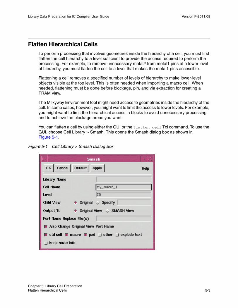
Library Data Preparation for IC Compiler User Guide Version F-2011.09
Flatten Hierarchical Cells
To perform processing that involves geometries inside the hierarchy of a cell, you must first flatten the cell hierarchy to a level sufficient to provide the access required to perform the processing. For example, to remove unnecessary metal2 from metal1 pins at a lower level of hierarchy, you must flatten the cell to a level that makes the metal1 pins accessible.
Flattening a cell removes a specified number of levels of hierarchy to make lower-level objects visible at the top level. This is often needed when importing a macro cell. When needed, flattening must be done before blockage, pin, and via extraction for creating a FRAM view.
The Milkyway Environment tool might need access to geometries inside the hierarchy of the cell. In some cases, however, you might want to limit the access to lower levels. For example, you might want to limit the hierarchical access in blocks to avoid unnecessary processing and to achieve the blockage areas you want.
You can flatten a cell by using either the GUI or the flatten_cell Tcl command. To use the GUI, choose Cell Library > Smash. This opens the Smash dialog box as shown in Figure 5-1.
Figure 5-1 Cell Library > Smash Dialog Box
Chapter 5: Library Cell Preparation Flatten Hierarchical Cells 5-3Chapter 5: Library Cell Preparation Flatten Hierarchical Cells 5-3
Library Data Preparation for IC Compiler User Guide F-2011.09Library Data Preparation for IC Compiler User Guide Version F-2011.09
In the Library Name text box, enter the name of the Milkyway library, or leave the box blank to flatten one or more cells in the currently open Milkyway library. In the cell name text box, enter the name of one cell or an asterisk character (*) to flatten all cells in the library.
The dialog box contains options to specify the number of hierarchical levels flattened, the types of views flattened, the type of new view created by flattening, and the handling of port names. For detailed information about these options, click the Help button in the dialog box or see the man page for the Tcl command flatten_cell in Tcl mode.
After you set the dialog box options, click OK. The Milkyway Environment tool traverses the hierarchy of each cell, flattens the hierarchy, and creates a new view of the cell as specified by the dialog box settings.
Flattening a cell in an unopened Milkyway library changes the contents of the unopened library. Flattening a cell in the open Milkyway library changes the cell in memory; you need to save the new or modified cell to keep the result.
Instead of using the GUI, you can use the equivalent Tcl command, flatten_cell. For details, see the man page for the flatten_cell command, available on SolvNet and in the Milkyway Environment tool.
Extract Blockage, Pin, and Via Information for FRAM View
In a Milkyway reference library that is fully prepared for use in IC Compiler, each cell usually has both a CEL view and a FRAM view. The CEL view contains all of the physical mask layers of the cell, whereas the FRAM view is an abstraction of the cell containing only the information needed for placement and routing at the next higher level of the design hierarchy.
When you place an instance of a cell, you use the FRAM view of the cell. The FRAM view includes the pin names and locations, the metal blockage areas where routes are not allowed, and the allowed via areas. Other cell features are omitted in the FRAM view. The exclusion of unnecessary data can reduce the database size, increase the routing accuracy, and reduce the routing time.
Figure 5-2 shows two views of a standard cell, an inverter. The CEL view is on the left and the FRAM view is on the right. The CEL view contains all of the mask layers of the cell, including the polysilicon, diffusion, and internal contact layers. The FRAM view has only the power rails, input and output pins, and via landing areas (via regions) over the input and output pins. Note that the extraction process slices all metal polygons into rectangles. The FRAM view contains all the information necessary to place the inverter cell in a site row and route the connections to the input and output of the cell.
Chapter 5: Library Cell Preparation Extract Blockage, Pin, and Via Information for FRAM View 5-4
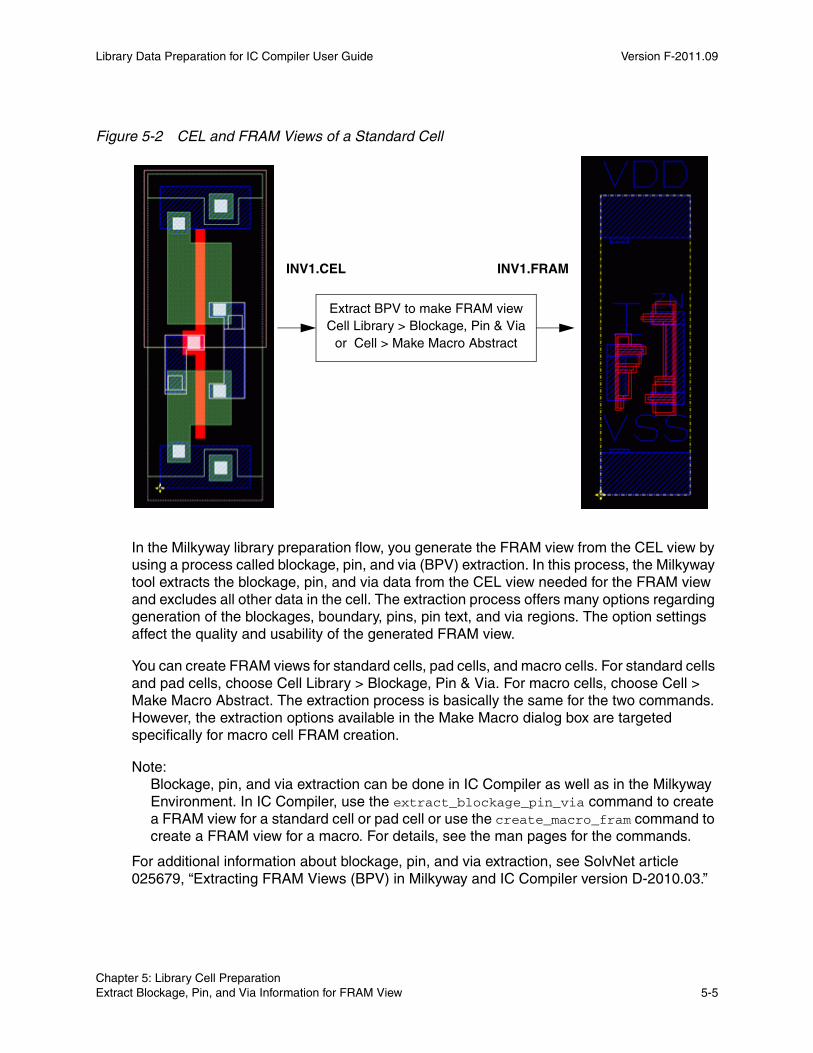
Library Data Preparation for IC Compiler User Guide Version F-2011.09
Figure 5-2 CEL and FRAM Views of a Standard Cell
INV1.CEL INV1.FRAM
Extract BPV to make FRAM viewCell Library > Blockage, Pin & Via
or Cell > Make Macro Abstract
In the Milkyway library preparation flow, you generate the FRAM view from the CEL view by using a process called blockage, pin, and via (BPV) extraction. In this process, the Milkyway tool extracts the blockage, pin, and via data from the CEL view needed for the FRAM view and excludes all other data in the cell. The extraction process offers many options regarding generation of the blockages, boundary, pins, pin text, and via regions. The option settings affect the quality and usability of the generated FRAM view.
You can create FRAM views for standard cells, pad cells, and macro cells. For standard cells and pad cells, choose Cell Library > Blockage, Pin & Via. For macro cells, choose Cell > Make Macro Abstract. The extraction process is basically the same for the two commands. However, the extraction options available in the Make Macro dialog box are targeted specifically for macro cell FRAM creation.
Note: Blockage, pin, and via extraction can be done in IC Compiler as well as in the Milkyway Environment. In IC Compiler, use the extract_blockage_pin_via command to create a FRAM view for a standard cell or pad cell or use the create_macro_fram command to create a FRAM view for a macro. For details, see the man pages for the commands.
For additional information about blockage, pin, and via extraction, see SolvNet article 025679, “Extracting FRAM Views (BPV) in Milkyway and IC Compiler version D-2010.03.”
Chapter 5: Library Cell Preparation Extract Blockage, Pin, and Via Information for FRAM View 5-5Chapter 5: Library Cell Preparation Extract Blockage, Pin, and Via Information for FRAM View 5-5

Library Data Preparation for IC Compiler User Guide F-2011.09Library Data Preparation for IC Compiler User Guide Version F-2011.09
Extraction From Standard Cells and Pad CellsTo perform blockage, pin, and via extraction in the Milkyway Environment to create a FRAM view for a standard cell or pad cell, choose Cell Library > Blockage, Pin & Via. This opens the Extract Blockage dialog box, like the example shown in Figure 5-3.
Figure 5-3 Cell Library > Blockage, Pin & Via Dialog Box
The buttons Extract Blockage, Extract Pin by Text, and Extract Via expand the dialog box to show the options related to the generation of blockages, pins, and vias, respectively. The Extract Via options are shown in the foregoing figure.
To perform FRAM view extraction, enter the name of the Milkyway library and the name of the cell from which to extract. To perform FRAM extraction for all cells in the library, enter an asterisk character (*) for the cell name, and select the type or types of cells from which to extract from the toggle buttons provided: “std/module cell,” “macro,” and “pad.”
Use the Generate Boundary toggle buttons to specify which boundary edges are to be determined by the extraction process. By default, the existing boundary edges of the CEL view are used without change. If you generate a new boundary, the boundary depends on the locations of the extracted blockages, pins, and via landing areas.
Chapter 5: Library Cell Preparation Extract Blockage, Pin, and Via Information for FRAM View 5-6
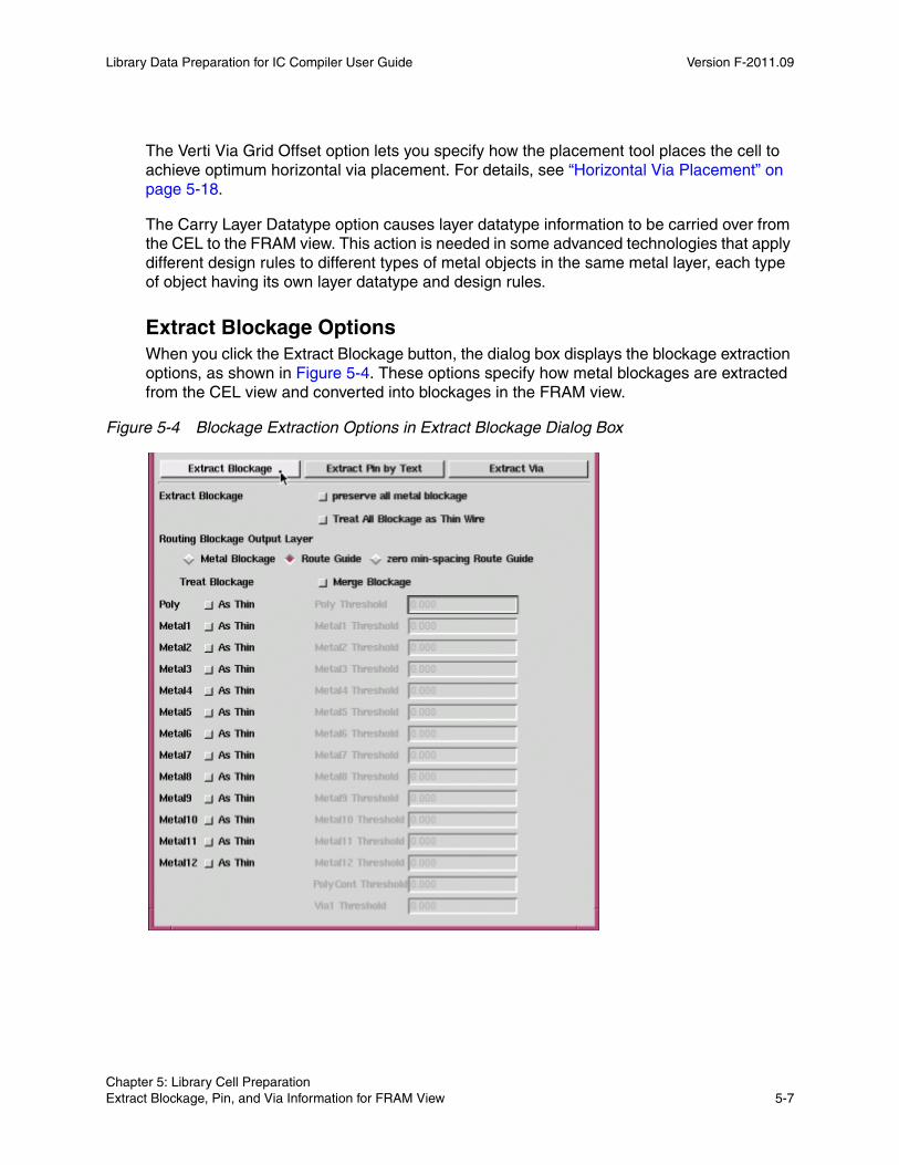
Library Data Preparation for IC Compiler User Guide Version F-2011.09
The Verti Via Grid Offset option lets you specify how the placement tool places the cell to achieve optimum horizontal via placement. For details, see “Horizontal Via Placement” on page 5-18.
The Carry Layer Datatype option causes layer datatype information to be carried over from the CEL to the FRAM view. This action is needed in some advanced technologies that apply different design rules to different types of metal objects in the same metal layer, each type of object having its own layer datatype and design rules.
Extract Blockage OptionsWhen you click the Extract Blockage button, the dialog box displays the blockage extraction options, as shown in Figure 5-4. These options specify how metal blockages are extracted from the CEL view and converted into blockages in the FRAM view.
Figure 5-4 Blockage Extraction Options in Extract Blockage Dialog Box
Chapter 5: Library Cell Preparation Extract Blockage, Pin, and Via Information for FRAM View 5-7Chapter 5: Library Cell Preparation Extract Blockage, Pin, and Via Information for FRAM View 5-7
Library Data Preparation for IC Compiler User Guide F-2011.09Library Data Preparation for IC Compiler User Guide Version F-2011.09
Blockage TypesSystem metal blockages defined in the CEL view can be retained in the FRAM view or converted into system metal blockages, route guides, or zero-minimum-spacing route guides in the FRAM view. Proper extraction of blockages can be used to prevent DRC violations between routes and cell-internal metal, while allowing the greatest possible flexibility to the router. You can choose to preserve all metal blockages or have them trimmed away from pins to allow route connections while preventing DRC violations. For a macro or pad cell, you can also choose to have some or all routing layers treated as thin wire rather than fat wire for blockage extraction and DRC purposes.
System metal blockage can be added to the CEL view or created automatically during FRAM view creation. It can be used to cover up the routing area of the cell. The router always treats system metal blockage as thin wire for design rule checking purposes.
Real metal blockage is a real metal layer in the FRAM view, either extracted from all metal geometries other than pins or converted from system metal blockages in the CEL view. The router observes all design rules, just like for any real metal.
Route guides are geometries in the design that guide the behavior of the router. The route guides produced by blockage extraction are route exclusion areas. The router treats ordinary route guides as thin metal but checks only basic spacing rules between the route guide and the route. The router treats zero-minimum-spacing route guides as geometries that routes can touch but not overlap.
Preserve All System Metal BlockageTo preserve all system metal blockage layers as they exist in the CEL view, select the “preserve all metal blockage” option. The system metal blockages are retained in the FRAM view and remain system metal blockage. Make sure that the preserved system metal blockages do not violate the design rules. This option is recommended for standard cell input in LEF format.
Treat Real Metal Blockage as Thin WireBy default, real metal blockages are treated as fat wire if fat or thin wire if thin for design rule checking purposes. The spacing rules can be different for thin versus fat wire, which affects the spacing required between routes and real metal blockages.
In macro and pad cells, the “Treat All Blockage as Thin Wire” option causes all real metal blockages to be treated as thin wire for design rule checking purposes. This option sets a flag on the FRAM model that tells the router to treat all real metal blockage layers as thin. This option setting also affects the trimming of real metal blockages during extraction.
Chapter 5: Library Cell Preparation Extract Blockage, Pin, and Via Information for FRAM View 5-8
Library Data Preparation for IC Compiler User Guide Version F-2011.09
To treat only some layers as thin, do not select the “Treat All Blockage as Thin Wire” option. Use the Treat Blockage options that you can set for each layer: “As Thin,” “block all,” or “merge.” If you select “As Thin” for a layer, the router trims the metal back to emulate the “treat as thin” behavior. In that case, the router sees the metal as fat, but because it has been trimmed back, the final effect is to observe the min spacing rule.
The amount by which the metal is trimmed back is:
(max value in fatTblSpacing) – (minSpacing)
Routing Blockage Output LayerThe Routing Blockage Output Layer options specify how metal blockage is implemented in the FRAM view: as system metal blockage, ordinary route guide, or zero-minimum-spacing route guide. The router recognizes all three types of layers as blockage and will not route over them, but the spacing rules vary from one type to another.
Treat Blockage As Thin and Merge BlockageUse the Treat Blockage options to control the extraction of real metal blockage layers on an individual layer basis.
The “As Thin” option causes the metal blockage to be trimmed back so that the router, in effect, treats the metal as thin for design rule checking purposes. See the previous section, “Treat Real Metal Blockage as Thin Wire” on page 5-8.
The “Merge Blockage” option merges geometries that are close together. If two nearby geometries are within the specified spacing threshold, the extraction process fills in the space between the two shapes, thereby creating a single larger shape for the blockage in the FRAM view. One possible value to use for the spacing threshold is twice the minSpacing value plus the minWidth value specified in the technology file. This is the narrowest space that could allow a single route to pass between two shapes in that layer.
Extract Pin by Text OptionsWhen you click the Extract Blockage button, the dialog box displays the blockage extraction options as shown in Figure 5-5. These options specify how pins are identified by text objects in the CEL view so that they can be properly extracted to make the FRAM view.
Chapter 5: Library Cell Preparation Extract Blockage, Pin, and Via Information for FRAM View 5-9Chapter 5: Library Cell Preparation Extract Blockage, Pin, and Via Information for FRAM View 5-9

Library Data Preparation for IC Compiler User Guide F-2011.09Library Data Preparation for IC Compiler User Guide Version F-2011.09
Figure 5-5 Extract Pin by Text Options in Extract Blockage Dialog Box
The “Extract Connectivity through” options cause the extraction process to traverse connectivity through the specified cut and via layers to identify connections between pins on different layers and extract the entire pin.
Select the “text fall through” option to use the metal layers beneath the origin of each text label to identify the geometry annotated by the text. Select the “double fall through” option if more than one geometry exists beneath the origin of a text label in two different layers and you want both to be named by the same text label.
For each of the layer text boxes (Poly Text, Metal1 Text, and so on), enter the name or number of the layer used to identify the geometries of that layer. Leave the box blank if the text layer is the same as the associated geometry layer.
Chapter 5: Library Cell Preparation Extract Blockage, Pin, and Via Information for FRAM View 5-10
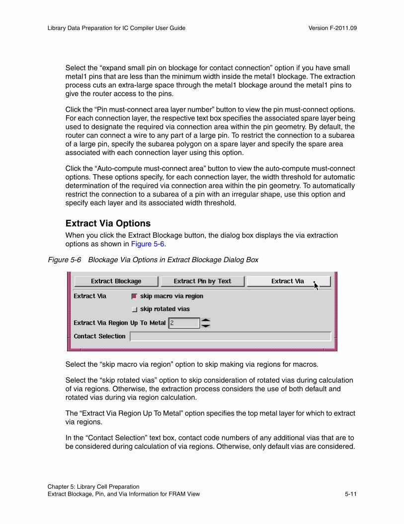
Library Data Preparation for IC Compiler User Guide Version F-2011.09
Select the “expand small pin on blockage for contact connection” option if you have small metal1 pins that are less than the minimum width inside the metal1 blockage. The extraction process cuts an extra-large space through the metal1 blockage around the metal1 pins to give the router access to the pins.
Click the “Pin must-connect area layer number” button to view the pin must-connect options. For each connection layer, the respective text box specifies the associated spare layer being used to designate the required via connection area within the pin geometry. By default, the router can connect a wire to any part of a large pin. To restrict the connection to a subarea of a large pin, specify the subarea polygon on a spare layer and specify the spare area associated with each connection layer using this option.
Click the “Auto-compute must-connect area” button to view the auto-compute must-connect options. These options specify, for each connection layer, the width threshold for automatic determination of the required via connection area within the pin geometry. To automatically restrict the connection to a subarea of a pin with an irregular shape, use this option and specify each layer and its associated width threshold.
Extract Via OptionsWhen you click the Extract Blockage button, the dialog box displays the via extraction options as shown in Figure 5-6.
Figure 5-6 Blockage Via Options in Extract Blockage Dialog Box
Select the “skip macro via region” option to skip making via regions for macros.
Select the “skip rotated vias” option to skip consideration of rotated vias during calculation of via regions. Otherwise, the extraction process considers the use of both default and rotated vias during via region calculation.
The “Extract Via Region Up To Metal” option specifies the top metal layer for which to extract via regions.
In the “Contact Selection” text box, contact code numbers of any additional vias that are to be considered during calculation of via regions. Otherwise, only default vias are considered.
Chapter 5: Library Cell Preparation Extract Blockage, Pin, and Via Information for FRAM View 5-11Chapter 5: Library Cell Preparation Extract Blockage, Pin, and Via Information for FRAM View 5-11

Library Data Preparation for IC Compiler User Guide F-2011.09Library Data Preparation for IC Compiler User Guide Version F-2011.09
Extraction From MacrosTo perform blockage, pin, and via extraction in the Milkyway Environment to create a FRAM view for a macro cell, choose Cell > Make Macro Abstract. This opens the Extract Blockage dialog box, like the example shown in Figure 5-7.
Figure 5-7 Cell > Make Macro Abstract Dialog Box
The buttons Extract Blockage, Extract Pin by Text, and Extract Via expand the dialog box to show the options related to the generation of blockages, pins, and vias, respectively. The Extract Via options are shown in the foregoing figure.
To perform FRAM view extraction, enter the name of the Milkyway library and the name of the cell from which to extract. By default, these text boxes are filled in with the name of the currently open Milkyway library and the name of the current cell.
Select the Execute Hierarchical Smart Smash by Hercules to perform hierarchical flattening using Hercules.
Extract Blockage OptionsWhen you click the Extract Blockage button, the dialog box displays the blockage extraction options, as shown in Figure 5-8. These options specify how metal blockages are extracted from the CEL view and converted into blockages in the FRAM view.
Chapter 5: Library Cell Preparation Extract Blockage, Pin, and Via Information for FRAM View 5-12
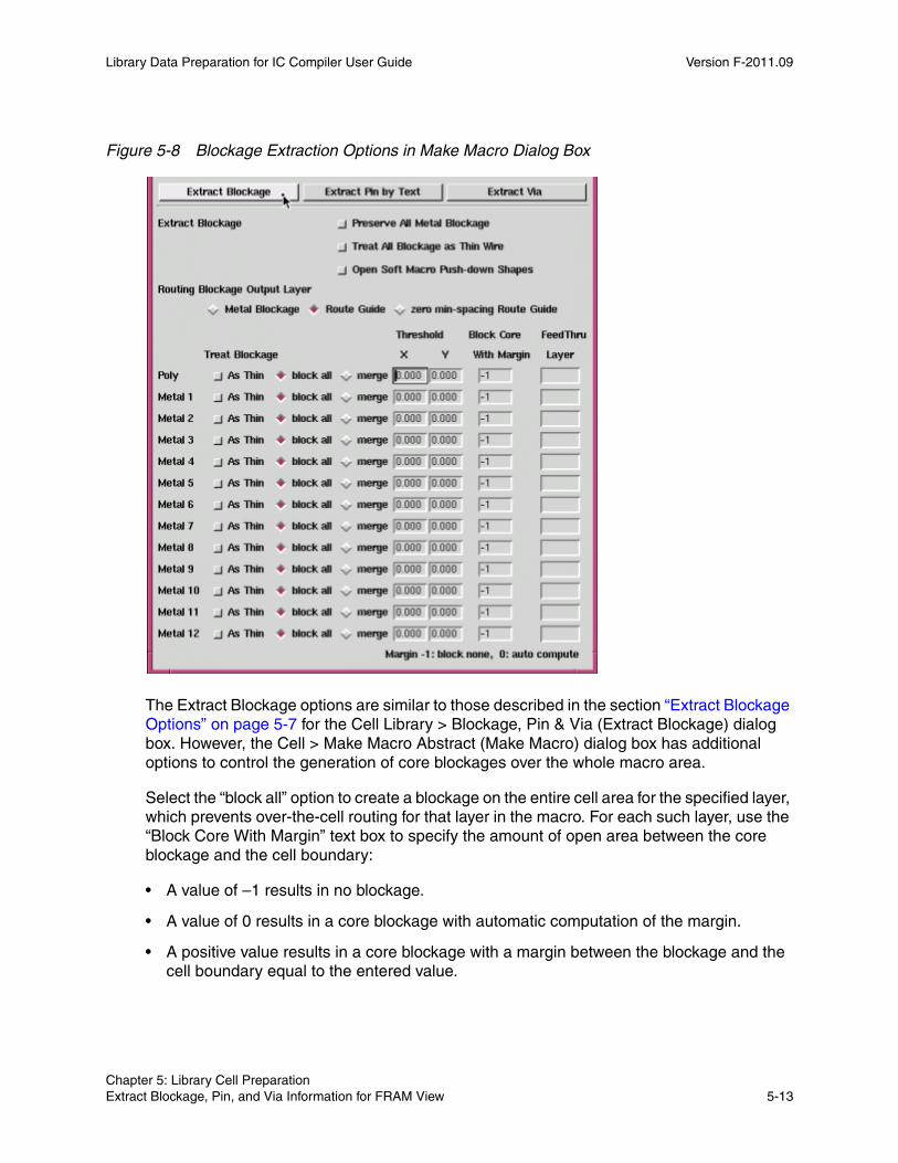
Library Data Preparation for IC Compiler User Guide Version F-2011.09
Figure 5-8 Blockage Extraction Options in Make Macro Dialog Box
The Extract Blockage options are similar to those described in the section “Extract Blockage Options” on page 5-7 for the Cell Library > Blockage, Pin & Via (Extract Blockage) dialog box. However, the Cell > Make Macro Abstract (Make Macro) dialog box has additional options to control the generation of core blockages over the whole macro area.
Select the “block all” option to create a blockage on the entire cell area for the specified layer, which prevents over-the-cell routing for that layer in the macro. For each such layer, use the “Block Core With Margin” text box to specify the amount of open area between the core blockage and the cell boundary:
• A value of –1 results in no blockage.
• A value of 0 results in a core blockage with automatic computation of the margin.
• A positive value results in a core blockage with a margin between the blockage and the cell boundary equal to the entered value.
Chapter 5: Library Cell Preparation Extract Blockage, Pin, and Via Information for FRAM View 5-13Chapter 5: Library Cell Preparation Extract Blockage, Pin, and Via Information for FRAM View 5-13

Library Data Preparation for IC Compiler User Guide F-2011.09Library Data Preparation for IC Compiler User Guide Version F-2011.09
In the “FeedThru Layer” text box, enter the name of a layer that reserves some areas that retain the metal as it exists in the original CEL view. This selection prevents the extraction process from covering the specified area with blockage and also prevents merging the metal geometries in that area.
The Extract Blockage dialog box allows a single merging threshold, whereas the Make Macro dialog box allows different thresholds to be entered for the X and Y directions.
Extract Pin by Text OptionsWhen you click the Extract Blockage button, the dialog box displays the blockage extraction options, as shown in Figure 5-9.
Figure 5-9 Extract Pin by Text Options in Make Macro Dialog Box
The Extract Pin by Text options of the Make Macro dialog box are similar to those described in the section “Extract Pin by Text Options” on page 5-9 for the Cell Library > Blockage, Pin & Via (Extract Blockage) dialog box.
Chapter 5: Library Cell Preparation Extract Blockage, Pin, and Via Information for FRAM View 5-14

Library Data Preparation for IC Compiler User Guide Version F-2011.09
Extract Via OptionsWhen you click the Extract Blockage button, the dialog box displays the blockage extraction options, as shown in Figure 5-10.
Figure 5-10 Blockage Via Options in Make Macro Dialog Box
The Extract Via options of the Make Macro dialog box are similar to those described in the section “Extract Via Options” on page 5-11 for the Cell Library > Blockage, Pin & Via (Extract Blockage) dialog box.
Identifying PinsThe extraction process identifies pins by reading text labels associated with geometries in the cells. Determining which text label refers to which geometry requires information regarding which layers are used for the text labels.
Layers for text labels can follow any of the following conventions:
• Text is on the same layer as the geometry it identifies.
• Text is on a different layer from the geometry it identifies.
• All text is on the same layer. The text location identifies the associated geometry.
In the case of multiple-layer pins with text on only one layer, you select the “Extract Connectivity” option in the “Extract Pin by Text” options to trace the connectivity of the pin and extract the entire pin.
Text on the Same Layer as Its GeometryWhen the text layers match the layers for the geometries they identify, you only need to make sure that “text fall through” is not selected in the dialog box. You do not need to specify the text layers associated with the interconnection metal.
Chapter 5: Library Cell Preparation Extract Blockage, Pin, and Via Information for FRAM View 5-15Chapter 5: Library Cell Preparation Extract Blockage, Pin, and Via Information for FRAM View 5-15
Library Data Preparation for IC Compiler User Guide F-2011.09Library Data Preparation for IC Compiler User Guide Version F-2011.09
Text on a Different Layer From Its GeometryWhen each geometry layer has one or more text layers associated with it, you need to supply the following text-to-metal information in the dialog box: “Poly Text” is the list of layers used for the text identifying poly geometries, “Metal1 Text” is the list of layers used for the text identifying Metal1 geometries, and so on.
Enter the names or numbers of the layers used for the text that annotates geometries on each interconnection metal, or leave the box blank if the text layer matches the geometry layer. To specify multiple layers, separate the names or numbers with commas.
All Text on the Same LayerWhen all text labels are on the same layer, you need to set the “Extract Pin by Text” options as follows:
• Select “text fall through” to look at the layers beneath the origin of each text label on the fall through text layer to identify a geometry annotated by the text. If more than one geometry exists beneath the origin of the text label, the extraction process selects the geometry according to the following priorities, from highest to lowest: Metal3, Metal2, Metal1, Poly.
• Select “double fall through” to look at the layers beneath the origin of each text label on a Metal2 geometry to identify a geometry (in addition to the Metal2 geometry) annotated by the text. If more than one geometry (besides the Metal2 geometry) exists beneath the origin of the text label, the extraction process selects the second geometry as Metal1 if present, and Poly otherwise.
Enter the name or the number of the Fall Through Text layer, the layer used for text labels. The extraction process reads each text label on the Fall Through Text layer to identify the pins represented by the geometry (or two geometries) beneath that text label.
Creating Blockage AreasMilkyway creates blockage areas by merging any geometries on the same layer that are within merging distance of each other except for pins. By default, the merging distance is twice the minSpacing value plus the minWidth value in the technology file. This is the narrowest space that can allow a single minimum-width route to pass through.
For example, if the technology file specifies a poly minSpacing of 2 and a poly minWidth of 4, the merging distance is 2*2 + 4 = 8. Therefore, in Figure 5-11, the extraction process merges the geometries on the left to create the blockage area on the right.
Chapter 5: Library Cell Preparation Extract Blockage, Pin, and Via Information for FRAM View 5-16
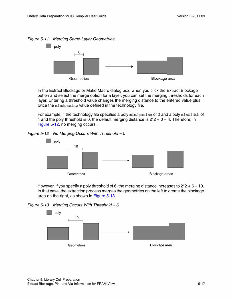
Library Data Preparation for IC Compiler User Guide Version F-2011.09
Figure 5-11 Merging Same-Layer Geometries
8
poly
Geometries Blockage area
In the Extract Blockage or Make Macro dialog box, when you click the Extract Blockage button and select the merge option for a layer, you can set the merging thresholds for each layer. Entering a threshold value changes the merging distance to the entered value plus twice the minSpacing value defined in the technology file.
For example, if the technology file specifies a poly minSpacing of 2 and a poly minWidth of 4 and the poly threshold is 0, the default merging distance is 2*2 + 0 = 4. Therefore, in Figure 5-12, no merging occurs.
Figure 5-12 No Merging Occurs With Threshold = 0
10
poly
Geometries Blockage areas
However, if you specify a poly threshold of 6, the merging distance increases to 2*2 + 6 = 10. In that case, the extraction process merges the geometries on the left to create the blockage area on the right, as shown in Figure 5-13.
Figure 5-13 Merging Occurs With Threshold = 6
10
poly
Geometries Blockage area
Chapter 5: Library Cell Preparation Extract Blockage, Pin, and Via Information for FRAM View 5-17Chapter 5: Library Cell Preparation Extract Blockage, Pin, and Via Information for FRAM View 5-17

Library Data Preparation for IC Compiler User Guide F-2011.09Library Data Preparation for IC Compiler User Guide Version F-2011.09
Horizontal Via PlacementTo specify how you want to place standard cells to achieve optimum horizontal via placement, use the Verti Via Grid Offset option in the Cell Library > Blockage, Pin & Via (Extract Blockage) dialog box.
Indicate how you want to place standard cells to achieve optimum horizontal via placement.
Option Instructs how to place cells so that
auto The maximum number of vias are on a vertical wire track
specify The left side of an unflipped cell or the right side of a flipped cell is at a distance equal to the value you enter from a vertical wire track
To place an unflipped cell so that its left side is on a vertical wire track or a flipped cell so that its right side is on a vertical wire track as shown in Figure 5-14, select “specify” and enter the value 0.
Figure 5-14 Specifying Placement of Cell on Vertical Wire Track
To place an unflipped cell so that its left side is a specified distance from the right of a vertical wire track or a flipped cell so that its right side is a specified distance from the left of a vertical wire track as shown in Figure 5-15, select “specify” and enter a positive number for the distance. This value must be less than the pitch of the vertical routing layer.
Figure 5-15 Specifying Placement of Cell at Specified Distance From Vertical Wire Track
+ +
Chapter 5: Library Cell Preparation Extract Blockage, Pin, and Via Information for FRAM View 5-18

Library Data Preparation for IC Compiler User Guide Version F-2011.09
Exclusion of Internal PinsYou can optionally exclude internal pins during blockage, pin, and via extraction. When you use this option, the FRAM view excludes the internal pins contained of the original CEL view, resulting in a simpler FRAM view without the unnecessary internal pins.
To invoke this option, set the Tcl variable external_pin_file to a list of text files or a list of .db files before you perform blockage, pin, and via extraction. The text files or .db files specify which pins are internal pins that are not be extracted. For example,
Milkyway> set_app_var external_pin_file {my_text_file.txt}
Milkyway> set_app_var external_pin_file {my_lib1.db my_lib2.df}
If you set the variable to the name a text file, you specify the names of the cells and their external pins explicitly in the text file using the following format:
cell_name1 {external_pin_name1 external_pin_name2 ...}cell_name2 {external_pin_name1 external_pin_name2 ...}
Wildcard characters are allowed in the file. For example,
buf* { A B OUT }
In this example, all cell names beginning with “buf” are defined to have the external pins A, B, and OUT. Any other pins in those cells are considered internal pins and are not extracted.
If you set the external_pin_file variable to the name of a .db file, the tool looks inside the .db file to determine which pins are external and internal for each cell. External pins are extracted, including both signal pins and pg_port pins, and internal pins are not extracted. Bias pg_port pins are always extracted, whether external or internal.
After you set the variable, when you perform blockage, pin, and via extraction using Cell Library > Blockage, Pin, & Via or Cell > Make Macro Abstract, the extraction process skips extraction of internal pins for the cells listed in the text files or .db files.
Set the Place-and-Route Boundary
Synopsys tools can use the place-and-route boundary to align wire tracks and power and ground rails during cell placement. The place-and-route boundary is the bounding box of the unit tiles used by a standard cell, as shown in Figure 5-16.
Chapter 5: Library Cell Preparation Set the Place-and-Route Boundary 5-19Chapter 5: Library Cell Preparation Set the Place-and-Route Boundary 5-19
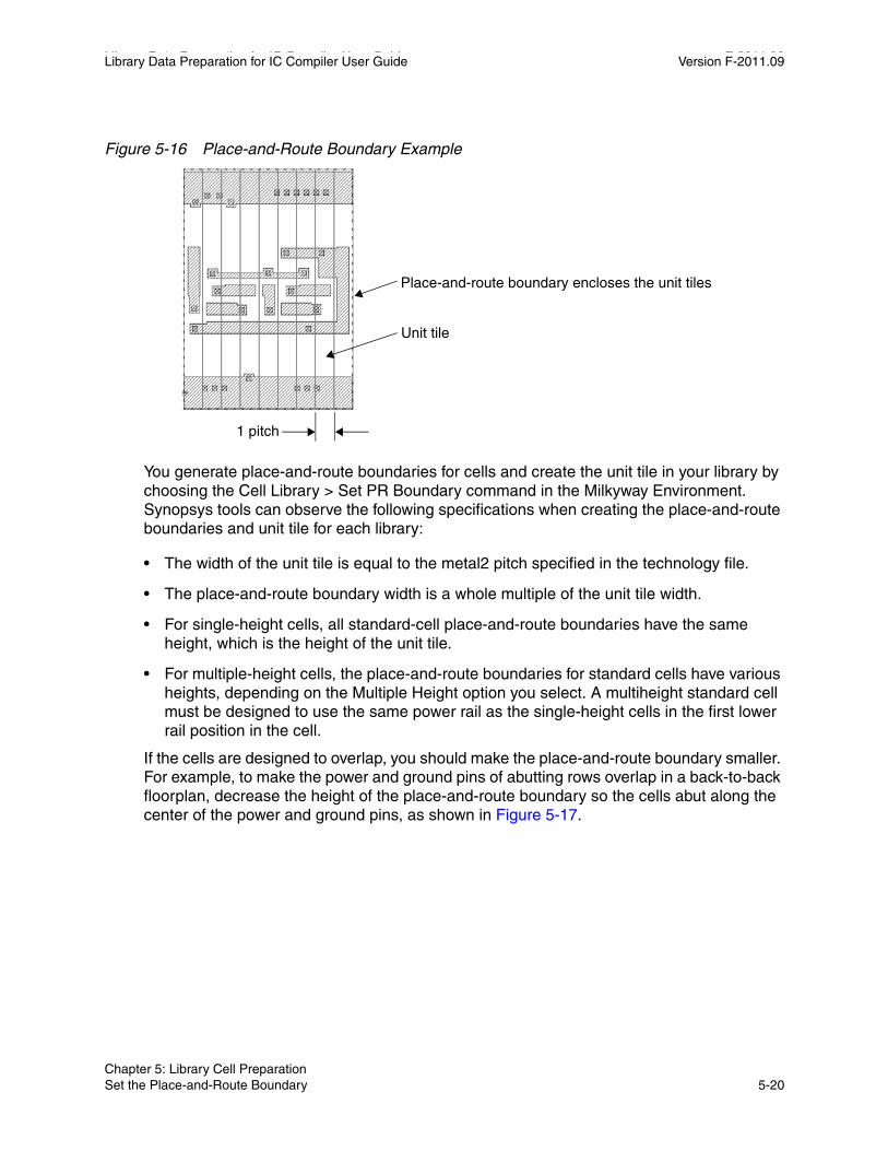
Library Data Preparation for IC Compiler User Guide F-2011.09Library Data Preparation for IC Compiler User Guide Version F-2011.09
Figure 5-16 Place-and-Route Boundary Example
1 pitch
Unit tile
Place-and-route boundary encloses the unit tiles
You generate place-and-route boundaries for cells and create the unit tile in your library by choosing the Cell Library > Set PR Boundary command in the Milkyway Environment. Synopsys tools can observe the following specifications when creating the place-and-route boundaries and unit tile for each library:
• The width of the unit tile is equal to the metal2 pitch specified in the technology file.
• The place-and-route boundary width is a whole multiple of the unit tile width.
• For single-height cells, all standard-cell place-and-route boundaries have the same height, which is the height of the unit tile.
• For multiple-height cells, the place-and-route boundaries for standard cells have various heights, depending on the Multiple Height option you select. A multiheight standard cell must be designed to use the same power rail as the single-height cells in the first lower rail position in the cell.
If the cells are designed to overlap, you should make the place-and-route boundary smaller. For example, to make the power and ground pins of abutting rows overlap in a back-to-back floorplan, decrease the height of the place-and-route boundary so the cells abut along the center of the power and ground pins, as shown in Figure 5-17.
Chapter 5: Library Cell Preparation Set the Place-and-Route Boundary 5-20
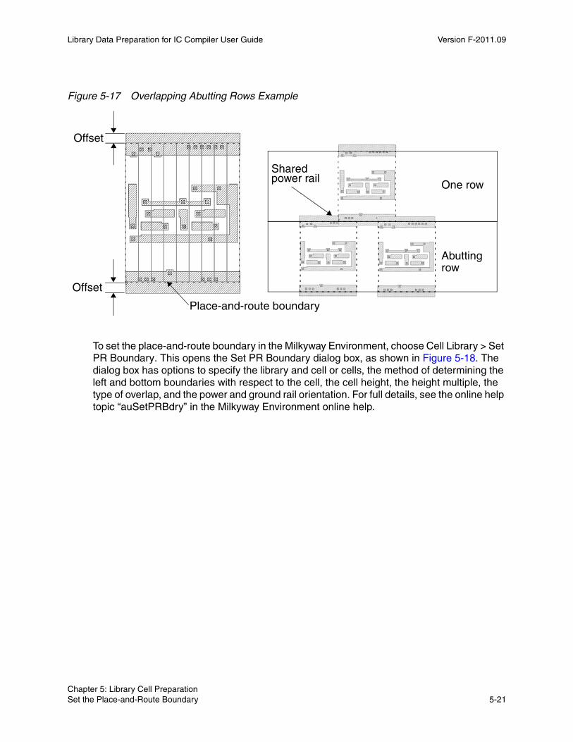
Library Data Preparation for IC Compiler User Guide Version F-2011.09
Figure 5-17 Overlapping Abutting Rows Example
Place-and-route boundary
Abutting
One rowSharedpower rail
Offset
Offset
row
To set the place-and-route boundary in the Milkyway Environment, choose Cell Library > Set PR Boundary. This opens the Set PR Boundary dialog box, as shown in Figure 5-18. The dialog box has options to specify the library and cell or cells, the method of determining the left and bottom boundaries with respect to the cell, the cell height, the height multiple, the type of overlap, and the power and ground rail orientation. For full details, see the online help topic “auSetPRBdry” in the Milkyway Environment online help.
Chapter 5: Library Cell Preparation Set the Place-and-Route Boundary 5-21Chapter 5: Library Cell Preparation Set the Place-and-Route Boundary 5-21
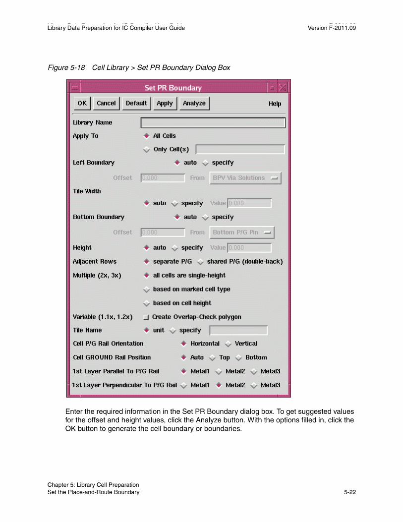
Library Data Preparation for IC Compiler User Guide F-2011.09Library Data Preparation for IC Compiler User Guide Version F-2011.09
Figure 5-18 Cell Library > Set PR Boundary Dialog Box
Enter the required information in the Set PR Boundary dialog box. To get suggested values for the offset and height values, click the Analyze button. With the options filled in, click the OK button to generate the cell boundary or boundaries.
Chapter 5: Library Cell Preparation Set the Place-and-Route Boundary 5-22
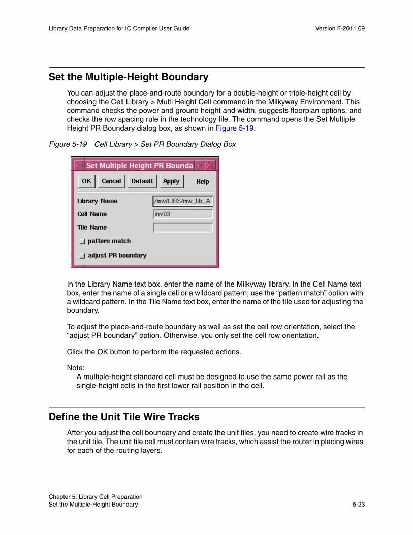
Library Data Preparation for IC Compiler User Guide Version F-2011.09
Set the Multiple-Height Boundary
You can adjust the place-and-route boundary for a double-height or triple-height cell by choosing the Cell Library > Multi Height Cell command in the Milkyway Environment. This command checks the power and ground height and width, suggests floorplan options, and checks the row spacing rule in the technology file. The command opens the Set Multiple Height PR Boundary dialog box, as shown in Figure 5-19.
Figure 5-19 Cell Library > Set PR Boundary Dialog Box
In the Library Name text box, enter the name of the Milkyway library. In the Cell Name text box, enter the name of a single cell or a wildcard pattern; use the “pattern match” option with a wildcard pattern. In the Tile Name text box, enter the name of the tile used for adjusting the boundary.
To adjust the place-and-route boundary as well as set the cell row orientation, select the “adjust PR boundary” option. Otherwise, you only set the cell row orientation.
Click the OK button to perform the requested actions.
Note: A multiple-height standard cell must be designed to use the same power rail as the single-height cells in the first lower rail position in the cell.
Define the Unit Tile Wire Tracks
After you adjust the cell boundary and create the unit tiles, you need to create wire tracks in the unit tile. The unit tile cell must contain wire tracks, which assist the router in placing wires for each of the routing layers.
Chapter 5: Library Cell Preparation Set the Multiple-Height Boundary 5-23Chapter 5: Library Cell Preparation Set the Multiple-Height Boundary 5-23
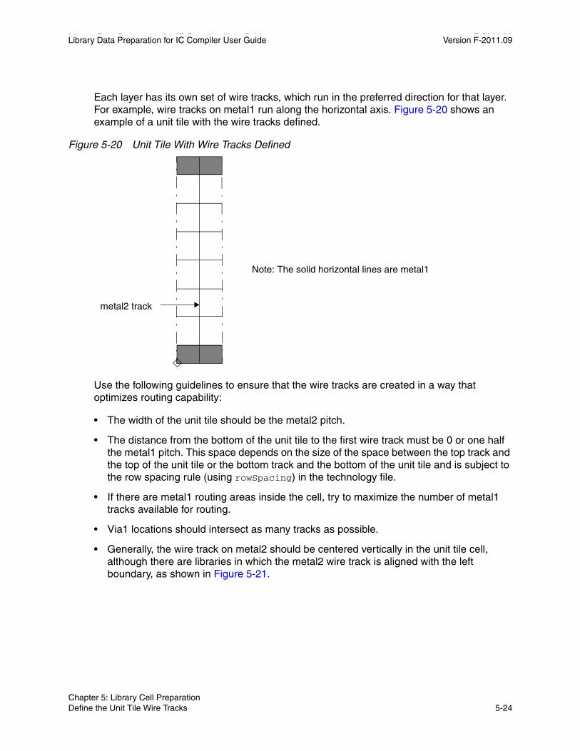
Library Data Preparation for IC Compiler User Guide F-2011.09Library Data Preparation for IC Compiler User Guide Version F-2011.09
Each layer has its own set of wire tracks, which run in the preferred direction for that layer. For example, wire tracks on metal1 run along the horizontal axis. Figure 5-20 shows an example of a unit tile with the wire tracks defined.
Figure 5-20 Unit Tile With Wire Tracks Defined
Note: The solid horizontal lines are metal1
metal2 track
Use the following guidelines to ensure that the wire tracks are created in a way that optimizes routing capability:
• The width of the unit tile should be the metal2 pitch.
• The distance from the bottom of the unit tile to the first wire track must be 0 or one half the metal1 pitch. This space depends on the size of the space between the top track and the top of the unit tile or the bottom track and the bottom of the unit tile and is subject to the row spacing rule (using rowSpacing) in the technology file.
• If there are metal1 routing areas inside the cell, try to maximize the number of metal1 tracks available for routing.
• Via1 locations should intersect as many tracks as possible.
• Generally, the wire track on metal2 should be centered vertically in the unit tile cell, although there are libraries in which the metal2 wire track is aligned with the left boundary, as shown in Figure 5-21.
Chapter 5: Library Cell Preparation Define the Unit Tile Wire Tracks 5-24

Library Data Preparation for IC Compiler User Guide Version F-2011.09
Figure 5-21 Standard Cell Placed on Array of Unit Tiles
Track intersectionsat ideal via1locations
Maximum number
Offset from place-and-
of metal1 tracks free
route boundary
Define the Wire TracksTo define the wire tracks, choose Wire Tracks > Define Unit Tile Wire Tracks in the Milkyway Environment. The command opens the Define Wire Track dialog box, as shown in Figure 5-22.
Chapter 5: Library Cell Preparation Define the Unit Tile Wire Tracks 5-25Chapter 5: Library Cell Preparation Define the Unit Tile Wire Tracks 5-25

Library Data Preparation for IC Compiler User Guide F-2011.09Library Data Preparation for IC Compiler User Guide Version F-2011.09
Figure 5-22 Wire Tracks > Define Unit Tile Wire Tracks Dialog Box
Use the option button to select the unit tile: unit, unit1, or specified. If there is more than one unit tile specified in the technology file, be sure to set the wire tracks for each one. For each layer in the unit tile, specify the offset and the preferred wire track direction. Click the OK button to complete the wire track definition.
Chapter 5: Library Cell Preparation Define the Unit Tile Wire Tracks 5-26
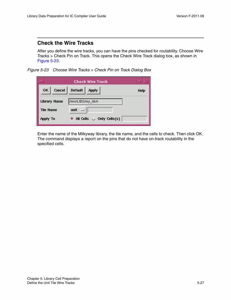
Library Data Preparation for IC Compiler User Guide Version F-2011.09
Check the Wire TracksAfter you define the wire tracks, you can have the pins checked for routability. Choose Wire Tracks > Check Pin on Track. This opens the Check Wire Track dialog box, as shown in Figure 5-23.
Figure 5-23 Choose Wire Tracks > Check Pin on Track Dialog Box
Enter the name of the Milkyway library, the tile name, and the cells to check. Then click OK. The command displays a report on the pins that do not have on-track routability in the specified cells.
Chapter 5: Library Cell Preparation Define the Unit Tile Wire Tracks 5-27Chapter 5: Library Cell Preparation Define the Unit Tile Wire Tracks 5-27

Library Data Preparation for IC Compiler User Guide F-2011.09Library Data Preparation for IC Compiler User Guide Version F-2011.09
Chapter 5: Library Cell Preparation Define the Unit Tile Wire Tracks 5-28

6Library Checking 6
Advanced IC design relies on high-quality libraries. Ensuring that the logical and physical libraries are correct and consistent is an essential step before design creation. You should check any new physical or logical library before you use it by running the check_library command in IC Compiler, as described in the following sections:
• Library Checking Overview
• Validating Logic Libraries
• Validating Physical Libraries
• Library Check Reporting Examples
6-1

Library Data Preparation for IC Compiler User Guide F-2011.09Library Data Preparation for IC Compiler User Guide Version F-2011.09
Library Checking Overview
Consistency between logic libraries and physical libraries is critical to achieving good results. You can perform library checking for logical and physical libraries with the check_library command in IC Compiler.
The Milkyway Environment also has a check_library command that can perform some of the same types of library checking as the command in IC Compiler. However, the command options, command option syntax, default behavior, and setup options are different between the two tools. For information about the Milkyway Environment command, see the man page for the command in the Milkyway Environment in Tcl mode or on SolvNet.
Library Compiler also has a check_library command, which is very similar to the command in IC Compiler. For more information about the command in Library Compiler, see the Library Compiler Modeling Timing, Signal Integrity, and Power in Technology Libraries User Guide, available in the Library Compiler documentation set on SolvNet.
To make sure that your libraries are consistent, run the check_library command in IC Compiler:
icc_shell> check_library
By default, the check_library command performs consistency checking between the logic libraries specified in the link_library variable and the physical libraries that are referenced in the current Milkyway design library. You can also check physical libraries for self-consistency or consistency between logic libraries and other logic libraries. This is the full command syntax:
check_library [-logic_library_name logic_library_names] [-mw_library_name physical_library_names] [-cells cell_list]
The libraries that you explicitly specify in the command override the default libraries. The -logic_library_name option specifies a list of logic libraries to be checked for consistency. If the -logic_library_name option is not explicitly specified but the set_min_library max_library command option is specified, the command checks the minimum and maximum libraries as a pair. If neither the -logic_library_name option nor the minimum and maximum libraries are specified but the link_library and search_path variables are set, the command groups the libraries in the list by cell set, and within each group, it checks the consistencies across all the libraries. Libraries that cannot be paired are not checked.
Use the -cells option to specify a list of cell names to check. If the cell names are not specified, all the cells in the library are checked. The check_library command returns a status message indicating whether the check was successful.
Chapter 6: Library Checking Library Checking Overview 6-2
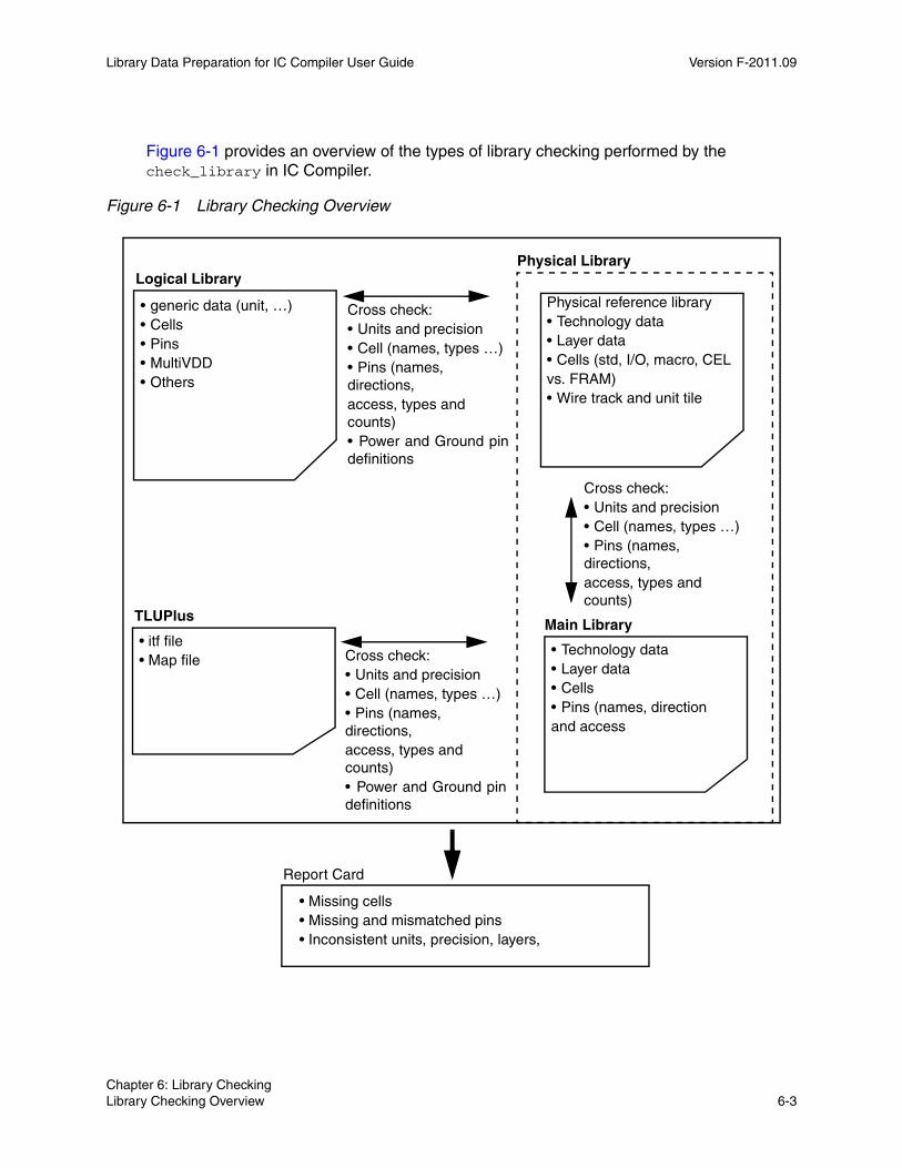
Library Data Preparation for IC Compiler User Guide Version F-2011.09
Figure 6-1 provides an overview of the types of library checking performed by the check_library in IC Compiler.
Figure 6-1 Library Checking Overview
• generic data (unit, …)• Cells• Pins• MultiVDD• Others
Physical Library
Physical reference library• Technology data• Layer data• Cells (std, I/O, macro, CELvs. FRAM)• Wire track and unit tile
Cross check:• Units and precision• Cell (names, types …)• Pins (names, directions,access, types and counts)• Power and Ground pin definitions
Logical Library
Cross check:• Units and precision• Cell (names, types …)• Pins (names, directions,access, types and counts)
• Technology data• Layer data• Cells• Pins (names, directionand access
• itf file• Map file
TLUPlus
Cross check:• Units and precision• Cell (names, types …)• Pins (names, directions,access, types and counts)• Power and Ground pin definitions
Report Card
Main Library
• Missing cells• Missing and mismatched pins• Inconsistent units, precision, layers,
Chapter 6: Library Checking Library Checking Overview 6-3Chapter 6: Library Checking Library Checking Overview 6-3

Library Data Preparation for IC Compiler User Guide F-2011.09Library Data Preparation for IC Compiler User Guide Version F-2011.09
By default, the check_library command verifies that all cells in the logic library and in the physical library also exist in the other library, including any physical-only cells, and that the pins on each cell are consistent between the logic library and the physical library. This validation includes consistency in naming, direction, and type, including power and ground pins.
Note: If the logic library does not contain pg_pin definitions, the command uses the power and ground pins as defined in the physical library.
You can control the types of library checking performed by the check_library command by using the set_check_library_options command. For example, you can explicitly specify the following types of library consistency checking:
• To verify that the area for each cell (other than pad cells) is consistent between the logic library and the physical library.
icc_shell> set_check_library_options -cell_area
• To verify that the cell footprints are consistent between the logic library and the physical library.
icc_shell> set_check_library_options -cell_footprint
• To verify that the same bus naming style is used in the logic library and the physical library.
icc_shell> set_check_library_options -bus_delimiter
Specify the option for each check that you would like to enable, or to enable all consistency checks, use the -logic_vs_physical option. For a full description of the options of the set_check_library_options command, see the man page for the command.
To reset the library checks to the default settings (cell name and pin consistency checks), run the set_check_library_options -reset command.
To see the enabled library consistency library checks, run the report_check_library_options -logic_vs_physical command.
If the check_library command reports any inconsistencies, you must fix them before you begin using the libraries.
Chapter 6: Library Checking Library Checking Overview 6-4
Library Data Preparation for IC Compiler User Guide Version F-2011.09
Validating Logic Libraries
You can use the check_library command to check the quality of a logic library. To perform these logic library checks, enable the specific checks you want by running the set_check_library_options command.
Table 6-1 shows the logic library checks and the set_check_library_options command options used to enable them.
Table 6-1 Logic Library Checks
Option Description
-compare {construct attribute value}
General logic library consistency checking.
-mcmm Logic library consistency checking for multicorner-multimode (MCMM) operation.
-scaling {timing noise power}
Logic library consistency checking for CCS timing, CCS noise, and CCS or NLDM power scaling.
-tolerance {type relative_tolerance absolute_tolerance}
The relative tolerance and an absolute tolerance for characterization value comparison.
-upf Logic library consistency checking for multivoltage and UPF.
-validate Logic library consistency checking for library characterization.
-logical Enables all the logic library checks.
-reset Resets the options to the default.
-all Specifies to check all items for the libraries, including logic versus physical and physical library checking.
Specify an option for each check that you would like to enable, or if you want to enable all logic library checks, use the -logical option. To reset the library checks to the default settings, run the set_check_library_options -reset command. To enable all checks for logic and physical libraries, use the -all option.
Chapter 6: Library Checking Validating Logic Libraries 6-5Chapter 6: Library Checking Validating Logic Libraries 6-5

Library Data Preparation for IC Compiler User Guide F-2011.09Library Data Preparation for IC Compiler User Guide Version F-2011.09
General Logic ChecksThe check_library command performs the following logic versus logic library general checks. For the libraries to pass a flow check, the general logic checks should not have any problems.
Library Group
For the library group, the check_library command reports the library version, library type, and whether the library is power and ground pin based. The command also checks to see if the libraries have the same units and the same slew trip points for CCS timing scaling. The command checks to see if the libraries have default operating conditions defined. The check_library command performs these checks, with the exception of the trip points check, by default. Use the set_check_library_options -scaling timing command to perform the trip points check.
Cell Group
The check_library command checks for the same number of cells in each library. It also checks the area, function_id, dont_use, and dont_touch attributes for cells with the same name for consistency. The check_library command performs these checks by default.
Pin and pg_pin Groups in the Cells
The check_library command checks to see if the libraries have the same number of pins, including PG pins. The command also checks to see if the PG pin names, directions, types, functions, and voltage_name in the two libraries are the same. Apart from these checks, the command also checks to see if the two libraries are the same in the following ways:
• The input_signal_level or output_signal_level for a rail-based library is the same, or the related_power_pin or related_ground_pin is the same for a pg_pin-based library.
• Derived pin_number attribute values are the same. If there is a mismatch, the command performs additional checking in an attempt to determine the cause.
The check_library command performs these checks by default.
Timing Arcs
The check_library command checks for timing arcs that have related pins, timing type, timing sense, and when conditions that match across the libraries. In any two sets of logic (technology) libraries with the same cell group, if such timing arcs are used in at least one design, they are checked for consistency between these libraries. The check_library command performs these checks by default.
Chapter 6: Library Checking Validating Logic Libraries 6-6
Library Data Preparation for IC Compiler User Guide Version F-2011.09
Specific Logic ChecksUse the set_check_library_options -compare construct command to specify that the check_library command compare all groups, subgroups, attributes, and characterized values, such as the timing, power, and current between two libraries.
Use the set_check_library_options -compare value command to specify that the check_library command compare two libraries for all characterized values.
Special ChecksSome flows and applications require special checking in addition to the general checks.
Use the set_check_library_options -scaling timing command to check for CCS timing scaling across the different libraries. This command checks for matching numbers of driver and load index values, consistent usage of receiver models, consistent waveform usage for characterization, and consistent usage of model compression.
Use the set_check_library_options -scaling noise command to check for CCS noise scaling, including consistent voltage index values, ordering of conditional “when” pin models, and number of noise models.
Use the set_check_library_options -scaling power command to check for CCS or NLPM power scaling to ensure that the libraries have the consistent modeling groups, tables, and attributes.
For voltage scaling, the check_library command checks that the voltages are no more than 20 percent apart for good accuracy. This check is performed for reporting and does not determine the success or failure of the check.
Use the set_check_library_options -upf command to check for multivoltage or UPF flows. The command then verifies that different models exist for different characterizations, different voltages are characterized, power devices have consistent and complete attributes, and power data is provided for all operating conditions.
Use the set_check_library_options -mcmm command to perform checking for a multicorner-multimode flow. The command then verifies that different characterization information exists for different operating conditions, cells have consistent attributes, and the power and power-down information exists and is consistent.
Use the set_check_library_options -tolerance {type rel_tol abs_tol ... } command to specify a relative tolerance and an absolute tolerance for characterization value comparison, such as delay values. The options for type are delay, slew, constraint, slew_index, load_index, time, power, current, energy and capacitance. If you specify an absolute tolerance, do not include the unit; the unit in the first library is used.
Chapter 6: Library Checking Validating Logic Libraries 6-7Chapter 6: Library Checking Validating Logic Libraries 6-7
Library Data Preparation for IC Compiler User Guide F-2011.09Library Data Preparation for IC Compiler User Guide Version F-2011.09
The following example specifies tolerances for time and power:
-tolerance {time 0.1 0.2 power 0.3 0.4}
If you do not specify tolerances for a type, the default values are used. The following default values are set in compliance with PrimeTime and the Library Quality Assurance System:
Load Index Time Power
Relative Tolerance 0.01 0.04 0.04
Absolute Tolerance 0.001pF 0.015ns 5pW
If you want to determine whether two libraries are identical by comparing them group by group and attribute by attribute, you can set the tolerances to smaller values.
Use the set_check_library_options -validate {timing} command to enable the following checks for library characterization:
• The same output load index for each individual cell between CCS and NLDM models and the same load indexes for CCS driver and CCS receiver.
• The same number of NLDM delay and slew indexes and values.
• The difference of delays between NLDM and CCS timing within an acceptable range for both compact CCS and expanded CCS.
• That two CCS driver model current waveforms, including compact CCS with expanded CCS data, are consistent within an acceptable margin.
Library Checking Report FormatThe check_library command performs checks on physical and logical libraries and generates reports. By default, the check_library command generates reports in ASCII format. For characterization data validation, comparison and analysis checks, you can specify that the report be in CSV (comma separated value) format, which is compatible with most spreadsheet programs.
The CSV format reports have the following two sections:
• Header and summary
• Comparison values by group type: timing, power, or noise
Chapter 6: Library Checking Validating Logic Libraries 6-8
Library Data Preparation for IC Compiler User Guide Version F-2011.09
To generate library checking reports in CSV format, you must first specify the report format for the check_library command using the set_check_library_options command. The syntax used to specify the report format is
set_check_library_options -report_format {csv[=csv_file_dir]}
By default, the reports are stored in the current working directory. To specify the location to store the reports, use the csv_file_dir argument.
When you perform multiple runs with the same settings, the reports directory is backed up to the csv_file_dir_bak directory.
Validating Physical Libraries
You can use the check_library command to check the quality of a Milkyway design library. To perform these physical library checks, you must enable the specific checks you want by running the set_check_library_options command. By default, the check_library command does not perform physical library checks.
Use the check_library command to check the data and quality for a specified library, as shown in the following example:
icc_shell> check_library -mw_library_name mw_lib_A
To set the physical library checks, run the set_check_library_options command. Table 6-2 shows the physical library checks and the options used to enable them.
Table 6-2 Physical Library Checks
Use this option To check for
-routeability The on-track accessibility of the physical pins.
-drc Design rule constraint (DRC) violations in the routing (FRAM) view of the cells. This requires write permission for the library directory.
-view_comparison Consistency between the layout (CEL) view and the routing (FRAM) view of the cells in reference library. Missing views and mismatched views from earlier FRAM views are reported.
-antenna Missing antenna properties for cells and missing antenna rules for routing layers.
-signal_em Missing signal electromigration rules for routing layers.
Chapter 6: Library Checking Validating Physical Libraries 6-9Chapter 6: Library Checking Validating Physical Libraries 6-9

Library Data Preparation for IC Compiler User Guide F-2011.09Library Data Preparation for IC Compiler User Guide Version F-2011.09
To see the physical library checks that are currently enabled, run the report_check_library_options -physical command.
Physical Library Checking Option Descriptions-routeability
Checks for physical pin on-track accessibility and quality of defined wire tracks. It reports the total number of pins without on-track routability and lists pin names, directions, layers, and tracks for each cell of this issue.
In the track column of the report, H denotes that the pin is not accessible on the Horizontal track, V denotes that the pin is not accessible on the Vertical track, and H&V denotes that the pin is not accessible on both H and V.
If a pin is reported as having poor accessibility, the pin might be routed by off-track wire during detail routing.
-same_name_cell Cells with identical names in different reference libraries. The names of the cells are reported.
-rectilinear_cell Coordinates of cells with rectangular or rectilinear boundaries and the boundaries for macro cells.
-phys_property {types} Physical properties. You can specify one or more of the following types: place, route, cell, and metal_density.
-physical_only_cell Physical-only cells, such as filler cells with and without metal, diode cells with antenna properties, and corner cells.
-rail view_data The power and ground (PG) rail data readiness in the CONN view and the data consistency with the FRAM view. The CONN view contains PG rail information for the PrimeRail tool.
-tech_consistency Consistency in the technology data between the design library and the reference libraries.
-tech The quality of the technology data for a reference library.
-cells Specifies a list of cell names. If not specified, all cells in the library are checked.
-all All options.
-reset Resets all options to the default values.
Table 6-2 Physical Library Checks (Continued)
Use this option To check for
Chapter 6: Library Checking Validating Physical Libraries 6-10
Library Data Preparation for IC Compiler User Guide Version F-2011.09
If a large number of pins is reported as having no on-track routability, you can adjust the offset values of the wire track (0 or half pitch preferred) and run the create_lib_track command to reduce the number of pins with poor accessibility. For a report example, see “Report for the -routeability Option” on page 6-14.
-view_comparison
Checks the CEL view against the FRAM view in the library and reports missing views and mismatched views. In the report table, columns CEL and FRAM list the cell name and cell version number. An X denotes that the cell is missing the view.
If a cell has a FRAM view that is earlier than its CEL view, it is marked as mismatched. None of the cell content, such as pins, is checked for mismatch. For a report example, see “Report for the -view_comparison Option” on page 6-14.
-antenna
Checks for a missing antenna property for cells and checks antenna rules in the layers. If an input pin is missing the gate size or an output pin is missing diode protection, it is counted as missing the property. If a macro is missing the hierarchical antenna property, it is counted as missing the property. For antenna rules, the mode, diode mode, default metal ratio, default cut ratio, and maximum ratio are reported. For a report example, see “Report for the -antenna Option” on page 6-15.
-signal_em
Checks for signal electromigration rule (current model and model type) for each routing layer. For a report example, see “Report for the -signal_em Option” on page 6-15.
-same_name_cell
Checks for cells with identical names among different reference libraries linked to the specified main library and the main library itself. If there are cells with the same name in multiple reference libraries, the first one in the reference control file is used. For a report example, see “Report for the -same_name_cell Option” on page 6-15.
-rectilinear_cell
Checks for cells with rectilinear boundaries. For a report example, see “Report for the -rectilinear_cell Option” on page 6-15.
-phys_property {place route}
Checks for placement and routing properties.
-phys_property {place} checks for placement properties for each standard cell, such as place and route boundary, cell height, unit tile, coordinate, and tile pattern. For macros, it reports cell boundary and height.
-phys_property {route} checks and reports routing properties for each routing layer. For a report example, see “Report for the -phys_property Option” on page 6-16.
Chapter 6: Library Checking Validating Physical Libraries 6-11Chapter 6: Library Checking Validating Physical Libraries 6-11

Library Data Preparation for IC Compiler User Guide F-2011.09Library Data Preparation for IC Compiler User Guide Version F-2011.09
-physical_only_cell
Checks for physical-only cells (filler cells with and without metal, diode cells with antenna properties, and corner cells). For a report example, see “Report for the -physical_only_cell Option” on page 6-16.
-rail view_data
Checks the power and ground (PG) rail data readiness in the CONN view and the data consistency with the FRAM view. The CONN view contains PG rail information for the PrimeRail tool. This check includes the port types and associated net names in the CONN view and matching ports and net names in the FRAM view.
-tech_consistency
Checks technology data for consistency between the main or design library specified in the check_library command and each reference library. It looks for problems such as missing layer data and mismatched technology data. For a report example, see “Report for the -tech_consistency Option” on page 6-16.
-tech
Checks the technology data for the specified library. This option differs from the -tech_consistency option in that it checks the technology data for a single library. The checking messages are similar to those from library creation and technology data replacement. This option requires write permission on the directory where the library resides.
-drc
Checks for DRC violations in the FRAM views of cells in the specified library. It lists the cells with DRC violations in table format with cell name, cell type, and error cell. For details of DRC violations, view the reported error cell information.
This option requires write permission on the directory where the library resides.
-cells {list cell_1, cell_2, cell_3, ... cell_n}
Specifies a list of cell names. If not specified, all cells in the library are checked. The -cells option can be specified with -routeability, -antenna, -rectilinear_cell, -phys_property {place}, and view_cmp. If specified with any other options, this option is ignored.
-all
Performs all checks described above.
-reset
Resets the options to the default values.
Chapter 6: Library Checking Validating Physical Libraries 6-12
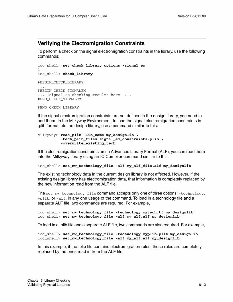
Library Data Preparation for IC Compiler User Guide Version F-2011.09
Verifying the Electromigration ConstraintsTo perform a check on the signal electromigration constraints in the library, use the following commands:
icc_shell> set_check_library_options -signal_em1icc_shell> check_library
#BEGIN_CHECK_LIBRARY...#BEGIN_CHECK_SIGNALEM... (signal EM checking results here) ...#END_CHECK_SIGNALEM...#END_CHECK_LIBRARY
If the signal electromigration constraints are not defined in the design library, you need to add them. In the Milkyway Environment, to load the signal electromigration constraints in .plib format into the design library, use a command similar to this:
Milkyway> read_plib -lib_name my_designlib \ -tech_plib_files signal_em_constraints.plib \ -overwrite_existing_tech
If the electromigration constraints are in Advanced Library Format (ALF), you can read them into the Milkyway library using an IC Compiler command similar to this:
icc_shell> set_mw_technology_file -alf my_alf_file.alf my_designlib
The existing technology data in the current design library is not affected. However, if the existing design library has electromigration data, that information is completely replaced by the new information read from the ALF file.
The set_mw_technology_file command accepts only one of three options: -technology, -plib, or -alf, in any one usage of the command. To load in a technology file and a separate ALF file, two commands are required. For example,
icc_shell> set_mw_technology_file -technology mytech.tf my_designlibicc_shell> set_mw_technology_file -alf my_alf.alf my_designlib
To load in a .plib file and a separate ALF file, two commands are also required. For example,
icc_shell> set_mw_technology_file -technology myplib.plib my_designlibicc_shell> set_mw_technology_file -alf my_alf.alf my_designlib
In this example, if the .plib file contains electromigration rules, those rules are completely replaced by the ones read in from the ALF file.
Chapter 6: Library Checking Validating Physical Libraries 6-13Chapter 6: Library Checking Validating Physical Libraries 6-13

Library Data Preparation for IC Compiler User Guide F-2011.09Library Data Preparation for IC Compiler User Guide Version F-2011.09
If you can get an updated incremental .plib file containing the electromigration data from your vendor, you can read it into the Milkyway library with the following IC Compiler command:
icc_shell> set_mw_technology_file \ -plib signal_em_constraints.plib my_designlib
Library Check Reporting Examples
After checking a library, IC Compiler generates a report in table format. To facilitate reading, each option check report starts with a #BEGIN_CHECK_ITEM and concludes with an #END_CHECK_ITEM string.
You can use the report_check_library_options command to report the values of the options set by the set_check_library_options command. For details, see the man page for the command.
The following check_library reports for different set_check_library_options settings are provided as examples. For more detailed information on a given check option report, see the man pages.
Report for the -routeability Option#BEGIN_CHECK_ROUTEABILITY Total number of pins without on-track routeability: 1 (out of 1125) List of pins with bad routeability -------------------------------------------------------------- Cell Name Pin Name Layer Direction Track -------------------------------------------------------------- SDN_ADDF_1 CI METAL2 Input H&V --------------------------------------------------------------#END_CHECK_ROUTEABILITY
Report for the -view_comparison Option#BEGIN_CHECK_VIEWCMPTotal number of cells missing CEL view: 0 (out of 997)Total number of cells missing FRAM view: 1 (out of 997)Total number of cells with mismatched view (CEL vs. FRAM): 0 (out of 997) X - cell missing view in the Table
List of cells with missing views ---------------------------------------------- Cell Name CEL FRAM ---------------------------------------------- cell_1 cell_1:1 X ----------------------------------------------#END_CHECK_VIEWCMP
Chapter 6: Library Checking Library Check Reporting Examples 6-14
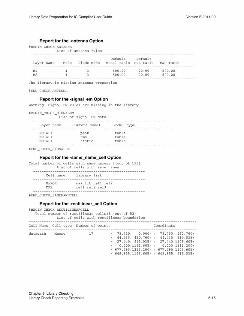
Library Data Preparation for IC Compiler User Guide Version F-2011.09
Report for the -antenna Option#BEGIN_CHECK_ANTENNA List of antenna rules --------------------------------------------------------------------------- Default Default Layer Name Mode Diode mode metal ratio cut ratio Max ratio --------------------------------------------------------------------------- M1 1 3 500.00 20.00 500.00 M2 1 3 500.00 20.00 500.00 ----------------------------------------------------------------------------The library is missing antenna properties
#END_CHECK_ANTENNA
Report for the -signal_em OptionWarning: Signal EM rules are missing in the library.
#BEGIN_CHECK_SIGNALEM List of signal EM data ----------------------------------------------------------------- Layer name Current model Model type ----------------------------------------------------------------- METAL1 peak table METAL1 rms table METAL1 static table -----------------------------------------------------------------#END_CHECK_SIGNALEM
Report for the -same_name_cell OptionTotal number of cells with same names: 2(out of 193) List of cells with same names ---------------------------------------------------- Cell name library list ---------------------------------------------------- MyXOR mainlib ref1 ref2 DFX ref1 ref2 ref3 ----------------------------------------------------#END_CHECK_SAMENAMECELL
Report for the -rectilinear_cell Option#BEGIN_CHECK_RECTILINEARCELL Total number of rectilinear cells:1 (out of 53) List of cells with rectilinear boundaries------------------------------------------------------------------------------Cell Name Cell type Number of points Coordinate------------------------------------------------------------------------------datapath Macro 17 ( 78.750, 0.000) ( 78.750, 490.760) ( 44.435, 490.760) ( 44.435, 915.035) ( 27.440, 915.035) ( 27.440,1143.605) ( 0.000,1143.605) ( 0.000,1313.200) ( 677.295,1313.200) ( 677.295,1143.605) ( 649.855,1143.605) ( 649.855, 915.035)
Chapter 6: Library Checking Library Check Reporting Examples 6-15Chapter 6: Library Checking Library Check Reporting Examples 6-15
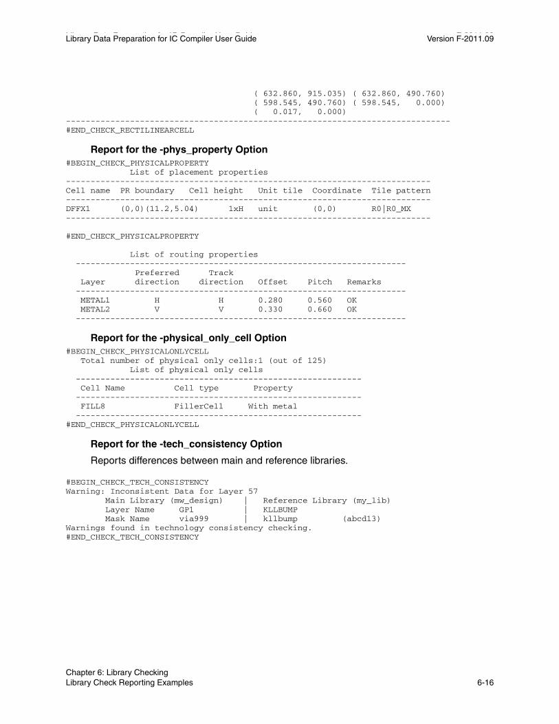
Library Data Preparation for IC Compiler User Guide F-2011.09Library Data Preparation for IC Compiler User Guide Version F-2011.09
( 632.860, 915.035) ( 632.860, 490.760) ( 598.545, 490.760) ( 598.545, 0.000) ( 0.017, 0.000)------------------------------------------------------------------------------#END_CHECK_RECTILINEARCELL
Report for the -phys_property Option#BEGIN_CHECK_PHYSICALPROPERTY List of placement properties--------------------------------------------------------------------------Cell name PR boundary Cell height Unit tile Coordinate Tile pattern--------------------------------------------------------------------------DFFX1 (0,0)(11.2,5.04) 1xH unit (0,0) R0|R0_MX--------------------------------------------------------------------------
#END_CHECK_PHYSICALPROPERTY
List of routing properties ------------------------------------------------------------------- Preferred Track Layer direction direction Offset Pitch Remarks ------------------------------------------------------------------- METAL1 H H 0.280 0.560 OK METAL2 V V 0.330 0.660 OK -------------------------------------------------------------------
Report for the -physical_only_cell Option#BEGIN_CHECK_PHYSICALONLYCELL Total number of physical only cells:1 (out of 125) List of physical only cells ---------------------------------------------------------- Cell Name Cell type Property ---------------------------------------------------------- FILL8 FillerCell With metal ----------------------------------------------------------#END_CHECK_PHYSICALONLYCELL
Report for the -tech_consistency Option
Reports differences between main and reference libraries.
#BEGIN_CHECK_TECH_CONSISTENCYWarning: Inconsistent Data for Layer 57 Main Library (mw_design) | Reference Library (my_lib) Layer Name GP1 | KLLBUMP Mask Name via999 | kllbump (abcd13)Warnings found in technology consistency checking.#END_CHECK_TECH_CONSISTENCY
Chapter 6: Library Checking Library Check Reporting Examples 6-16

7Using Milkyway Libraries in IC Compiler 7
IC Compiler uses the Milkyway database as the storage format for physical library cells and physical chip layout information, including placement and routing results. The entire chip is a single cell built out of lower-level blocks, which are also cells. These blocks are built out of smaller blocks, and so on, down to the level of leaf-level cells. The physical representations of these cells are stored in Milkyway libraries.
Usage of Milkyway libraries in IC Compiler is described in the following sections:
• Milkyway Library Structure
• Milkyway Reference Libraries
• Opening and Closing Milkyway Libraries
• Opening and Closing Milkyway Cells
• Creating New Milkyway Libraries and Cells
• Reading and Writing GDSII and OASIS in IC Compiler
• Milkyway Database Versions
7-1
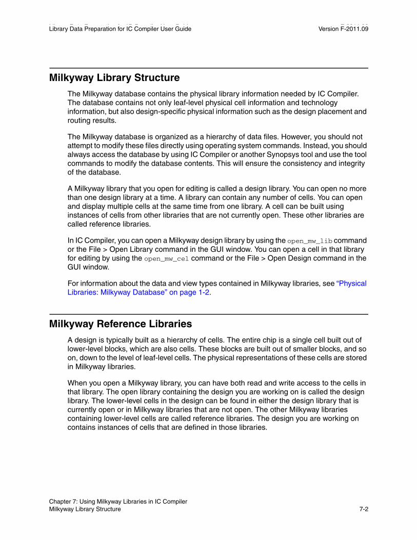
Library Data Preparation for IC Compiler User Guide F-2011.09Library Data Preparation for IC Compiler User Guide Version F-2011.09
Milkyway Library Structure
The Milkyway database contains the physical library information needed by IC Compiler. The database contains not only leaf-level physical cell information and technology information, but also design-specific physical information such as the design placement and routing results.
The Milkyway database is organized as a hierarchy of data files. However, you should not attempt to modify these files directly using operating system commands. Instead, you should always access the database by using IC Compiler or another Synopsys tool and use the tool commands to modify the database contents. This will ensure the consistency and integrity of the database.
A Milkyway library that you open for editing is called a design library. You can open no more than one design library at a time. A library can contain any number of cells. You can open and display multiple cells at the same time from one library. A cell can be built using instances of cells from other libraries that are not currently open. These other libraries are called reference libraries.
In IC Compiler, you can open a Milkyway design library by using the open_mw_lib command or the File > Open Library command in the GUI window. You can open a cell in that library for editing by using the open_mw_cel command or the File > Open Design command in the GUI window.
For information about the data and view types contained in Milkyway libraries, see “Physical Libraries: Milkyway Database” on page 1-2.
Milkyway Reference Libraries
A design is typically built as a hierarchy of cells. The entire chip is a single cell built out of lower-level blocks, which are also cells. These blocks are built out of smaller blocks, and so on, down to the level of leaf-level cells. The physical representations of these cells are stored in Milkyway libraries.
When you open a Milkyway library, you can have both read and write access to the cells in that library. The open library containing the design you are working on is called the design library. The lower-level cells in the design can be found in either the design library that is currently open or in Milkyway libraries that are not open. The other Milkyway libraries containing lower-level cells are called reference libraries. The design you are working on contains instances of cells that are defined in those libraries.
Chapter 7: Using Milkyway Libraries in IC Compiler Milkyway Library Structure 7-2

Library Data Preparation for IC Compiler User Guide Version F-2011.09
A reference library typically contains data that you do not modify yourself. For example, a reference library might contain standard cells provided by an ASIC vendor, intellectual property provided by an IP block seller, or lower-level blocks designed by another group at your company. Design information that you create or modify yourself must be stored in a design library.
The terms “design library” and “reference library” describe a one-way relationship between two Milkyway libraries. If you define mw_lib_B to be a reference library of design library mw_lib_A, then cells contained in mw_lib_B can used to build cells contained in mw_lib_A. However, this does not imply that cells contained in mw_lib_A can be used to build cells in mw_lib_B.
A given Milkyway library can serve as both a design library and a reference library. For example, you can define mw_lib_B to be a reference library of mw_lib_A and define mw_lib_C to be a reference library of mw_lib_B. Then cells in mw_lib_C can be used to build designs in mw_lib_B, and cells in mw_lib_B can be used to build cells in mw_lib_A. Thus, mw_lib_B is a reference library of mw_lib_A and also a design library to mw_lib_C, as shown in Figure 7-1.
Figure 7-1 Design and Reference Library Relationships Example 1
Milkyway librarymw_lib_A
Milkyway librarymw_lib_B
Milkyway librarymw_lib_C
Reference library
Design library
Reference library
Design library
LIBRARY /mw/LIBS/mw_lib_A REFERENCE /mw/LIBS/mw_lib_B
LIBRARY /mw/LIBS/mw_lib_B REFERENCE /mw/LIBS/mw_lib_C
Each reference library definition is one level deep. In Figure 7-1, cells in mw_lib_C cannot be used directly in mw_lib_A because the relationship is two levels deep. However, library mw_lib_C can also be explicitly defined as a reference library of mw_lib_A, which would allow its cells to be used directly in mw_lib_A. See Figure 7-2.
Chapter 7: Using Milkyway Libraries in IC Compiler Milkyway Reference Libraries 7-3Chapter 7: Using Milkyway Libraries in IC Compiler Milkyway Reference Libraries 7-3
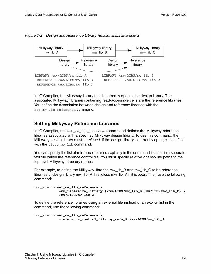
Library Data Preparation for IC Compiler User Guide F-2011.09Library Data Preparation for IC Compiler User Guide Version F-2011.09
Figure 7-2 Design and Reference Library Relationships Example 2
Milkyway librarymw_lib_A
Milkyway librarymw_lib_B
Milkyway librarymw_lib_C
Reference library
Design library
Reference library
Design library
LIBRARY /mw/LIBS/mw_lib_A REFERENCE /mw/LIBS/mw_lib_B REFERENCE /mw/LIBS/mw_lib_C
LIBRARY /mw/LIBS/mw_lib_B REFERENCE /mw/LIBS/mw_lib_C
In IC Compiler, the Milkyway library that is currently open is the design library. The associated Milkyway libraries containing read-accessible cells are the reference libraries. You define the association between design and reference libraries with the set_mw_lib_reference command.
Setting Milkyway Reference LibrariesIn IC Compiler, the set_mw_lib_reference command defines the Milkyway reference libraries associated with a specified Milkyway design library. To use this command, the Milkyway design library must be closed. If the design library is currently open, close it first with the close_mw_lib command.
You can specify the list of reference libraries explicitly in the command itself or in a separate text file called the reference control file. You must specify relative or absolute paths to the top-level Milkyway directory names.
For example, to define the Milkyway libraries mw_lib_B and mw_lib_C to be reference libraries of design library mw_lib_A, first close mw_lib_A if it is open. Then use the following command:
icc_shell> set_mw_lib_reference \ -mw_reference_library {/mw/LIBS/mw_lib_B /mw/LIBS/mw_lib_C} \ /mw/LIBS/mw_lib_A
To define the reference libraries using an external file instead of an explicit list in the command, use the following command:
icc_shell> set_mw_lib_reference \ -reference_control_file my_refs_A /mw/LIBS/mw_lib_A
Chapter 7: Using Milkyway Libraries in IC Compiler Milkyway Reference Libraries 7-4

Library Data Preparation for IC Compiler User Guide Version F-2011.09
You specify an absolute or relative path to the reference control file as well as to the Milkyway design library. The file format is described in the next section, “Milkyway Reference Control File.”
You can also use the IC Compiler main GUI window to specify the reference libraries. If a Milkyway library is currently open, close it using File > Close Library. Then choose File > Set Library Reference. The Set Library Reference dialog box has a browse button that lets you browse for the directory paths to design library and reference libraries, as shown in Figure 7-3.
Figure 7-3 File > Set Library Reference and Select Directory Dialog Boxes
To generate a report showing a list of the reference libraries defined for a particular design library, use the report_mw_lib with the -mw_reference_library option. For example,
icc_shell> report_mw_lib -mw_reference_library mw_lib_A/mw/LIBS/mw_lib_B/mw/LIBS/mw_lib_C
If you do not specify which Milkyway design library to report, the currently open Milkyway library is reported.
Chapter 7: Using Milkyway Libraries in IC Compiler Milkyway Reference Libraries 7-5Chapter 7: Using Milkyway Libraries in IC Compiler Milkyway Reference Libraries 7-5
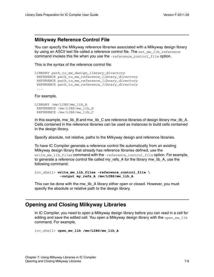
Library Data Preparation for IC Compiler User Guide F-2011.09Library Data Preparation for IC Compiler User Guide Version F-2011.09
Milkyway Reference Control FileYou can specify the Milkyway reference libraries associated with a Milkyway design library by using an ASCII text file called a reference control file. The set_mw_lib_reference command invokes this file when you use the -reference_control_file option.
This is the syntax of the reference control file:
LIBRARY path_to_mw_design_library_directory REFERENCE path_to_mw_reference_library_directory REFERENCE path_to_mw_reference_library_directory REFERENCE path_to_mw_reference_library_directory ...
For example,
LIBRARY /mw/LIBS/mw_lib_A REFERENCE /mw/LIBS/mw_lib_B REFERENCE /mw/LIBS/mw_lib_C
In this example, mw_lib_B and mw_lib_C are reference libraries of design library mw_lib_A. Cells contained in the reference libraries can be used as instances to build cells contained in the design library.
Specify absolute, not relative, paths to the Milkyway design and reference libraries.
To have IC Compiler generate a reference control file automatically from an existing Milkyway design library that already has reference libraries defined, use the write_mw_lib_files command with the -reference_control_file option. For example, to generate a reference control file called my_refs_A for the library mw_lib_A, use the following command:
icc_shell> write_mw_lib_files -reference_control_file \ -output my_refs_A /mw/LIBS/mw_lib_A
This can be done with the mw_lib_A library either open or closed. However, you must specify the absolute or relative path to the design library.
Opening and Closing Milkyway Libraries
In IC Compiler, you need to open a Milkyway design library before you can read in a cell for editing and save the edited cell. You open a Milkyway design library with the open_mw_lib command. For example,
icc_shell> open_mw_lib /mw/LIBS/mw_lib_A
Chapter 7: Using Milkyway Libraries in IC Compiler Opening and Closing Milkyway Libraries 7-6
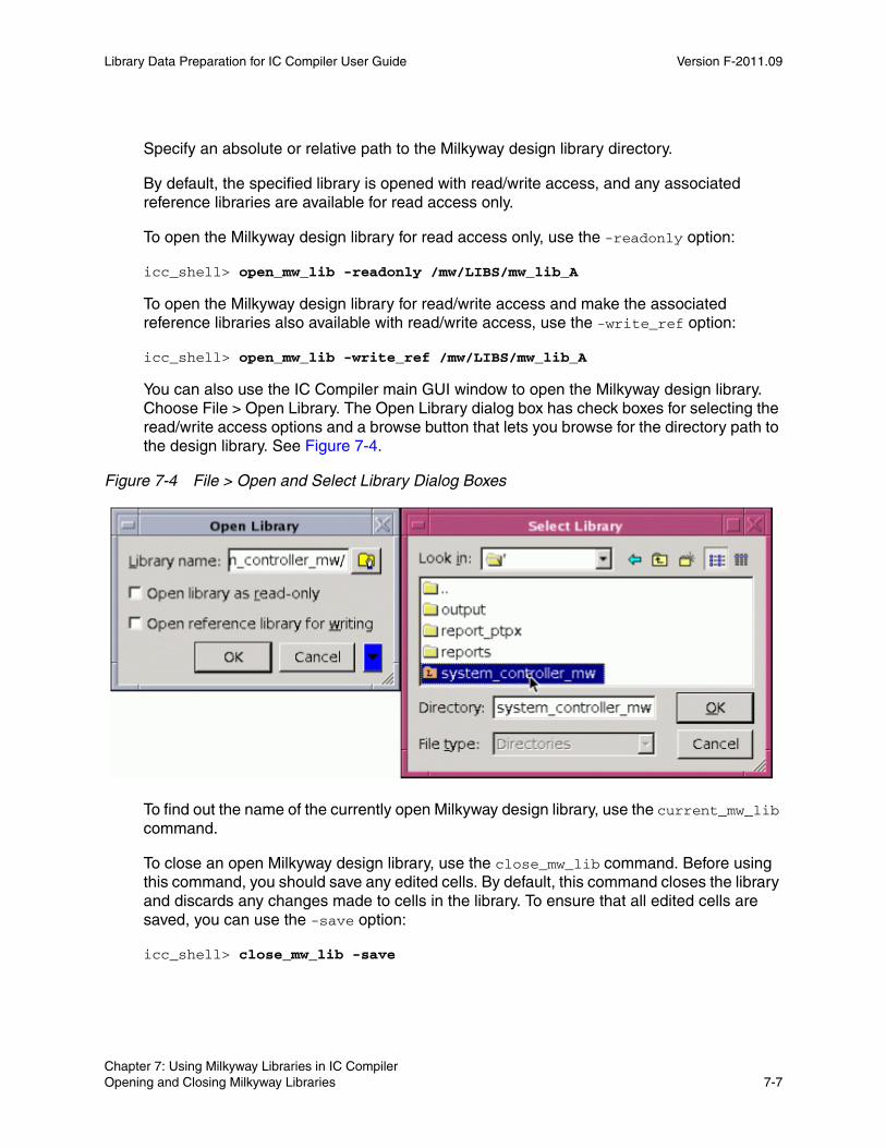
Library Data Preparation for IC Compiler User Guide Version F-2011.09
Specify an absolute or relative path to the Milkyway design library directory.
By default, the specified library is opened with read/write access, and any associated reference libraries are available for read access only.
To open the Milkyway design library for read access only, use the -readonly option:
icc_shell> open_mw_lib -readonly /mw/LIBS/mw_lib_A
To open the Milkyway design library for read/write access and make the associated reference libraries also available with read/write access, use the -write_ref option:
icc_shell> open_mw_lib -write_ref /mw/LIBS/mw_lib_A
You can also use the IC Compiler main GUI window to open the Milkyway design library. Choose File > Open Library. The Open Library dialog box has check boxes for selecting the read/write access options and a browse button that lets you browse for the directory path to the design library. See Figure 7-4.
Figure 7-4 File > Open and Select Library Dialog Boxes
To find out the name of the currently open Milkyway design library, use the current_mw_lib command.
To close an open Milkyway design library, use the close_mw_lib command. Before using this command, you should save any edited cells. By default, this command closes the library and discards any changes made to cells in the library. To ensure that all edited cells are saved, you can use the -save option:
icc_shell> close_mw_lib -save
Chapter 7: Using Milkyway Libraries in IC Compiler Opening and Closing Milkyway Libraries 7-7Chapter 7: Using Milkyway Libraries in IC Compiler Opening and Closing Milkyway Libraries 7-7
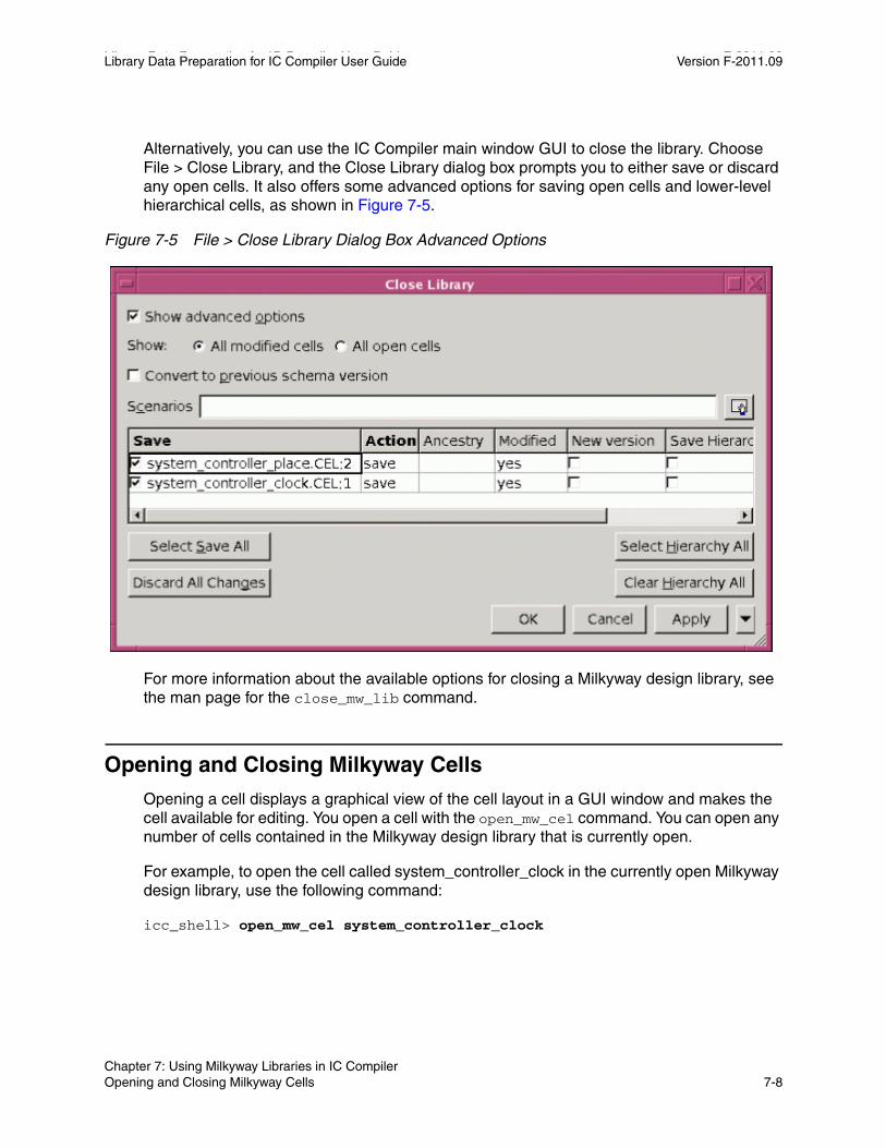
Library Data Preparation for IC Compiler User Guide F-2011.09Library Data Preparation for IC Compiler User Guide Version F-2011.09
Alternatively, you can use the IC Compiler main window GUI to close the library. Choose File > Close Library, and the Close Library dialog box prompts you to either save or discard any open cells. It also offers some advanced options for saving open cells and lower-level hierarchical cells, as shown in Figure 7-5.
Figure 7-5 File > Close Library Dialog Box Advanced Options
For more information about the available options for closing a Milkyway design library, see the man page for the close_mw_lib command.
Opening and Closing Milkyway Cells
Opening a cell displays a graphical view of the cell layout in a GUI window and makes the cell available for editing. You open a cell with the open_mw_cel command. You can open any number of cells contained in the Milkyway design library that is currently open.
For example, to open the cell called system_controller_clock in the currently open Milkyway design library, use the following command:
icc_shell> open_mw_cel system_controller_clock
Chapter 7: Using Milkyway Libraries in IC Compiler Opening and Closing Milkyway Cells 7-8
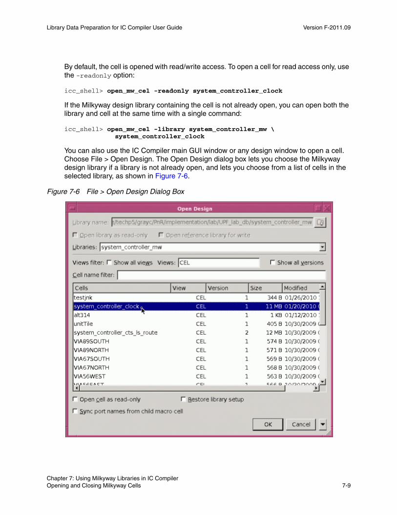
Library Data Preparation for IC Compiler User Guide Version F-2011.09
By default, the cell is opened with read/write access. To open a cell for read access only, use the -readonly option:
icc_shell> open_mw_cel -readonly system_controller_clock
If the Milkyway design library containing the cell is not already open, you can open both the library and cell at the same time with a single command:
icc_shell> open_mw_cel -library system_controller_mw \ system_controller_clock
You can also use the IC Compiler main GUI window or any design window to open a cell. Choose File > Open Design. The Open Design dialog box lets you choose the Milkyway design library if a library is not already open, and lets you choose from a list of cells in the selected library, as shown in Figure 7-6.
Figure 7-6 File > Open Design Dialog Box
Chapter 7: Using Milkyway Libraries in IC Compiler Opening and Closing Milkyway Cells 7-9Chapter 7: Using Milkyway Libraries in IC Compiler Opening and Closing Milkyway Cells 7-9

Library Data Preparation for IC Compiler User Guide F-2011.09Library Data Preparation for IC Compiler User Guide Version F-2011.09
For more information about the available options for opening a design, see the man page for the open_mw_cel command.
To find out the name of the cell currently open for editing, use the current_mw_cel command or look at the title bar of the cell layout window.
You can open multiple cells contained in the currently open Milkyway library. Each open cell is displayed in its own GUI window like the one shown in Figure 7-7.
Figure 7-7 Cell Layout Window Example
One of the open cells is considered the current cell for editing. To find out which cell is the current cell, use the current_mw_cel command. For example,
icc_shell> current_mw_cel{system_controller_clock}
To change the current cell, simply click in the GUI window containing the cell you want to edit, bringing that window to the foreground. Alternatively, you can use the current_mw_cel command to specify the desired current cell:
icc_shell> current_mw_cel system_controller_route
Chapter 7: Using Milkyway Libraries in IC Compiler Opening and Closing Milkyway Cells 7-10
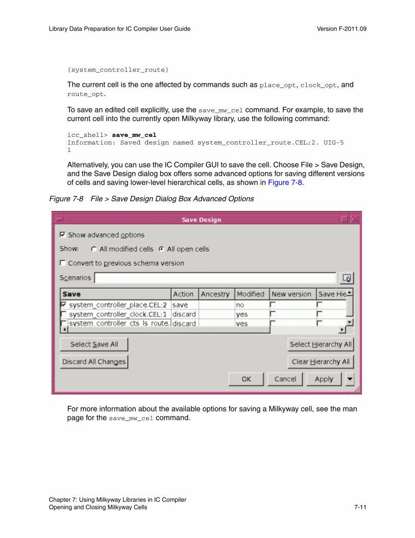
Library Data Preparation for IC Compiler User Guide Version F-2011.09
{system_controller_route}
The current cell is the one affected by commands such as place_opt, clock_opt, and route_opt.
To save an edited cell explicitly, use the save_mw_cel command. For example, to save the current cell into the currently open Milkyway library, use the following command:
icc_shell> save_mw_celInformation: Saved design named system_controller_route.CEL;2. UIG-51
Alternatively, you can use the IC Compiler GUI to save the cell. Choose File > Save Design, and the Save Design dialog box offers some advanced options for saving different versions of cells and saving lower-level hierarchical cells, as shown in Figure 7-8.
Figure 7-8 File > Save Design Dialog Box Advanced Options
For more information about the available options for saving a Milkyway cell, see the man page for the save_mw_cel command.
Chapter 7: Using Milkyway Libraries in IC Compiler Opening and Closing Milkyway Cells 7-11Chapter 7: Using Milkyway Libraries in IC Compiler Opening and Closing Milkyway Cells 7-11

Library Data Preparation for IC Compiler User Guide F-2011.09Library Data Preparation for IC Compiler User Guide Version F-2011.09
To close an open cell, use the close_mw_cel command. Before using this command, you should save the edited cell. By default, this command closes all open cells and discards any changes made to them. To ensure that all edited cells are saved, you can use the -save option:
icc_shell> close_mw_cel -save
Alternatively, you can use the IC Compiler GUI to close the cell. Choose File > Close Design, and the Close Design dialog box prompts you to save or discard any open cells. It also offers some advanced options for saving open cells and lower-level hierarchical cells, similar to the Save Design dialog box.
For more information about the available options for closing a Milkyway cell, see the man page for the close_mw_cel command.
Creating New Milkyway Libraries and Cells
In IC Compiler, you can easily create new, empty Milkyway design libraries for storing designs by using the create_mw_lib command. You can also copy existing Milkyway libraries with the copy_mw_lib command and then modify the contents of the copied library. The split_mw_lib command splits a hierarchical design library into separate design libraries, one for each top-level cell, so that different teams can work on those blocks independently.
Within a given Milkyway library, you can create new cells by using the create_mw_cel command or by copying existing cells with the copy_mw_cel command.
Creating and Copying Milkyway LibrariesBefore you can create a new Milkyway library for storing designs, you must have a technology file (.tf file) to specify the basic parameters for the library. The cells you add to the library must be consistent with this technology file.
To create a new Milkyway library called my_lib_2 in the /mw/LIB path with the technology file my_techfile.tf, use the following command:
icc_shell> create_mw_lib -technology my_techfile.tf mw_lib_2
Alternatively, in the IC Compiler GUI, choose File > Create Library. This opens the Create Library dialog box, which displays the options for creating the new library, as shown in Figure 7-9.
Chapter 7: Using Milkyway Libraries in IC Compiler Creating New Milkyway Libraries and Cells 7-12

Library Data Preparation for IC Compiler User Guide Version F-2011.09
Figure 7-9 File > Create Library Dialog Box
The create_mw_lib command and the Create Library dialog box have options to specify the name of the new Milkyway library, the name of the associated technology file, the names of the associated Milkyway reference libraries, and the bus naming style. For details, see the man page for the create_mw_lib command.
To copy an existing Milkyway design library, use the copy_mw_lib command. For example,
icc_shell> copy_mw_lib -from /mw/LIBS/mw_lib_A /mw/LIBS/mw_lib_A_bak
If you omit the -from option, the currently open library is copied and then closed.
Alternatively, in the IC Compiler GUI, choose File > Copy Library. The Copy Library dialog box lets you browse for the library to copy and browse for the directory in which to store the copied library.
Chapter 7: Using Milkyway Libraries in IC Compiler Creating New Milkyway Libraries and Cells 7-13Chapter 7: Using Milkyway Libraries in IC Compiler Creating New Milkyway Libraries and Cells 7-13

Library Data Preparation for IC Compiler User Guide F-2011.09Library Data Preparation for IC Compiler User Guide Version F-2011.09
Creating and Copying Milkyway CellsTo create a new, empty cell in the currently open Milkyway design library, use the create_mw_cel command. For example,
icc_shell> create_mw_cel my_new_cell
To copy a cell, you must have read permission from the source Milkyway library and read/write permission for the target Milkyway library. Use the copy_mw_cel command.
For example, the following command copies cell_A to cell_B in the currently open Milkyway design library:
icc_shell> copy_mw_cel -from cell_A -to cell_B
Alternatively, in the IC Compiler GUI, choose File > Copy Design. This opens the Copy Design dialog box, which displays the options for copying a cell, as shown in Figure 7-10.
Figure 7-10 File > Copy Design Dialog Box
Chapter 7: Using Milkyway Libraries in IC Compiler Creating New Milkyway Libraries and Cells 7-14
Library Data Preparation for IC Compiler User Guide Version F-2011.09
The copy_mw_cel command and the Copy Design dialog box have options to specify the name of the existing cell to copy, the name of the new cell to be created, the source and destination libraries, and whether to copy the lower-level hierarchical cells as well as the specified cell. For details, see the man page for the copy_mw_cel command.
Splitting a Milkyway Design LibraryThe split_mw_lib command splits a hierarchical design library into separate design libraries, one for each top-level cell, so that different teams can work on those blocks independently. Each library is assigned a new name by adding a prefix to the cell name.
For example, to split the top-level cell called chip_top contained in a design library called myDesignLib into a different library for each top-level cell, use the following command:
icc_shell> split_mw_lib -from_library myDesignLib chip_top
The command has options to specify the source library directory, the destination directory, and the prefix used to create the new library names. There is also an option for checking the potential results without actually performing the library split. For details, see the man page for the split_mw_lib command.
Reading and Writing GDSII and OASIS in IC Compiler
You can read GDSII and OASIS data into the Milkyway database by using the read_stream command in IC Compiler. Similarly, you can write design data in GDSII and OASIS format by using the write_stream command in IC Compiler.
read_streamThe read_stream command in IC Compiler lets you read design data in GDSII or OASIS format into IC Compiler and save that data in Milkyway cell format. You can use this command to convert library cell information in GDSII or OASIS format into a form that can be used in IC Compiler.
The set_read_stream_options command lets you set several data stream-in options, such as how to handle cells that already exist in the Milkyway library and how to handle cell boundary layers. You can also specify the following:
• A cell-type definition file, which identifies the function of each cell: standard cell, pad cell, filler cell, macro, and so on. If this file is not provided, all cells are assumed to be standard cells. For information about the file format, see “Cell-Type Definition File” on page 3-3.
Chapter 7: Using Milkyway Libraries in IC Compiler Reading and Writing GDSII and OASIS in IC Compiler 7-15Chapter 7: Using Milkyway Libraries in IC Compiler Reading and Writing GDSII and OASIS in IC Compiler 7-15
Library Data Preparation for IC Compiler User Guide F-2011.09Library Data Preparation for IC Compiler User Guide Version F-2011.09
• A layer mapping file, which identifies the corresponding layer names in the GDSII or OASIS file versus the Milkyway database. If this file is not provided, the layer names defined in the GDSII or OASIS data stream are retained in the Milkyway database. For information about the file format, see “Layer Mapping File: GDSII or OASIS to Milkyway” on page 3-5.
After you set the stream-in options, you can view the option settings with the report_read_stream_options command.
To read in the GDSII or OASIS file, use the read_stream command. This is the command syntax:
read_stream [-lib_name lib_name] [-format gds | oasis] stream_file_name
You must specify at least the input file name. The default format is GDSII, so to read the design in OASIS format, you must use the -format oasis option. For example,
icc_shell> read_stream -format oasis my_design.oasis
write_streamThe write_stream command in IC Compiler lets you write out design data in GDSII or OASIS format. The GDSII or OASIS data can then be used for mask creation or for input to external tools.
The set_write_stream_options command lets you set many file generation options such as naming conventions, name mapping, hierarchical depth, via flattening, and file compression. You can use the command multiple times to set individual options incrementally. You can report the option settings with the report_write_stream_options command. For full details, see the man page for the set_write_stream_options command.
After you set the options, you use the write_stream command to write out the design in GDSII or OASIS format. This is the syntax of the command:
write_stream [-lib_name lib_name] [-format gds | oasis] [-cells list_of_cells] [-cell_file cell_name_file] stream_file_name
Chapter 7: Using Milkyway Libraries in IC Compiler Reading and Writing GDSII and OASIS in IC Compiler 7-16

Library Data Preparation for IC Compiler User Guide Version F-2011.09
You must specify at least the output file name. The default format is GDSII, so to write the design in OASIS format, you must use the -format oasis option. For example,
icc_shell> write_stream -format oasis my_design.oasis
By default, the command writes out all cells in the library that is currently open. To restrict the output to a specified library or specified cells, use the -lib_name, -cells or -cell_file option. For more information, see the man page for the write_stream command.
Alternatively, in the IC Compiler GUI, choose File > Export > Write Stream. This opens the Write Stream dialog box, which displays the options for writing GDSII and OASIS as shown in Figure 7-11. The dialog box has the same options as the write_stream command. Click OK to generate the GDSII or OASIS file.
Figure 7-11 File > Export > Write Stream Dialog Box in IC Compiler
Chapter 7: Using Milkyway Libraries in IC Compiler Reading and Writing GDSII and OASIS in IC Compiler 7-17Chapter 7: Using Milkyway Libraries in IC Compiler Reading and Writing GDSII and OASIS in IC Compiler 7-17
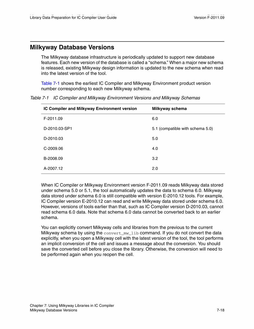
Library Data Preparation for IC Compiler User Guide F-2011.09Library Data Preparation for IC Compiler User Guide Version F-2011.09
Milkyway Database Versions
The Milkyway database infrastructure is periodically updated to support new database features. Each new version of the database is called a “schema.” When a major new schema is released, existing Milkyway design information is updated to the new schema when read into the latest version of the tool.
Table 7-1 shows the earliest IC Compiler and Milkyway Environment product version number corresponding to each new Milkyway schema.
Table 7-1 IC Compiler and Milkyway Environment Versions and Milkyway Schemas
IC Compiler and Milkyway Environment version Milkyway schema
F-2011.09 6.0
D-2010.03-SP1 5.1 (compatible with schema 5.0)
D-2010.03 5.0
C-2009.06 4.0
B-2008.09 3.2
A-2007.12 2.0
When IC Compiler or Milkyway Environment version F-2011.09 reads Milkyway data stored under schema 5.0 or 5.1, the tool automatically updates the data to schema 6.0. Milkyway data stored under schema 6.0 is still compatible with version E-2010.12 tools. For example, IC Compiler version E-2010.12 can read and write Milkyway data stored under schema 6.0. However, versions of tools earlier than that, such as IC Compiler version D-2010.03, cannot read schema 6.0 data. Note that schema 6.0 data cannot be converted back to an earlier schema.
You can explicitly convert Milkyway cells and libraries from the previous to the current Milkyway schema by using the convert_mw_lib command. If you do not convert the data explicitly, when you open a Milkyway cell with the latest version of the tool, the tool performs an implicit conversion of the cell and issues a message about the conversion. You should save the converted cell before you close the library. Otherwise, the conversion will need to be performed again when you reopen the cell.
Chapter 7: Using Milkyway Libraries in IC Compiler Milkyway Database Versions 7-18

Library Data Preparation for IC Compiler User Guide Version F-2011.09
When you open a cell and an implicit update is performed, and you want to save the updated cell and keep a backup copy of the old cell, use the save_mw_cel command with the -increase_version option to save the updated design under a new cell version number. Alternatively, you can use the -as option and specify a different name under which to save the cell.
Using the convert_mw_lib command to convert all your data is recommended. This ensures complete conversion of your data and is more efficient than converting cells one at a time. To make a backup copy of your library before performing the conversion, run the version of IC Compiler or the Milkyway Environment under the previous version and use the copy_mw_lib command.
To save time when converting a Milkyway design library to the new schema, use the remove_mw_cel command to remove cells in the design library that are no longer needed before you run the convert_mw_lib command.
To convert all of the cells contained in the Milkyway design library called mw_lib_A to the latest schema, use the following command:
icc_shell> convert_mw_lib -all /mw/LIBS/mw_lib_A
All CEL and ILM views in the library are converted. FRAM views are not affected.
Only the cells contained in the specified library are converted. Lower-level cells referenced in the design but contained in other libraries are not converted.
To convert the cell named cell_A in library mw_lib_A, use the following command:
icc_shell> convert_mw_lib -cell_name cell_A /mw/LIBS/mw_lib_A
When you use the -cell_name option, all child soft macro cells referenced by the specified cell are converted along with that cell if those cells are contained in the same Milkyway library. If the reference cells are loaded into memory, the in-memory versions are updated but not implicitly saved into their respective reference libraries.
Note: The convert_mw_lib command also works in the Milkyway Environment tool in Tcl mode. After a cell is converted by any Synopsys tool to the latest schema, the cell will work with all Synopsys tools of the same release.
Chapter 7: Using Milkyway Libraries in IC Compiler Milkyway Database Versions 7-19Chapter 7: Using Milkyway Libraries in IC Compiler Milkyway Database Versions 7-19

Library Data Preparation for IC Compiler User Guide F-2011.09Library Data Preparation for IC Compiler User Guide Version F-2011.09
Chapter 7: Using Milkyway Libraries in IC Compiler Milkyway Database Versions 7-20

AAserver, Amonitor, and Null Display A
The following sections describe the software processes required by the Milkyway Environment tool and how to run the tool in batch mode:
• AServer and AMonitor
• Null Display
A-1
Library Data Preparation for IC Compiler User Guide F-2011.09Library Data Preparation for IC Compiler User Guide Version F-2011.09
AServer and AMonitor
AServer is a server process that allows different processes to communicate with each other. Its primary purpose is to allow a tool based on Milkyway to fork a process, run as an executable, through AMonitor.
Each workstation should have only one AServer process per platform running at a time, no matter how many instances of a tool you are executing. This rule is necessary because the port number used by AServer is hard-coded, and any tool based on Milkyway tries to connect to that hard-coded port when starting up.
If AServer fails to start up because the port is already in use by another application, you can set the AServerPort environment variable to a free port number as shown in the following example:
% setenv AServerPort 1978
When you set the AServerPort variable to a free port number, such as 1978, AServer determines whether the port is available. If it is available, the tool connects to it.
If the port is not available, AServer fails to start. If this happens, you will need to reset the AServerPort variable to another free port number until AServer successfully starts up. You can get additional free port numbers from your system administrator.
When all tools connected to the port are disconnected, AServer terminates itself. You can also end the AServer process by issuing the following command:
% kill -9 processID
Ending the process is not recommended and should be used only in cases where there are no tools based on Milkyway running and AServer does not exit. Each tool process has one AMonitor process associated with it. Therefore, AMonitor quits if you terminate the tool process.
Null Display
As an alternative to using the GUI, you can run a script in batch mode by using the -nullDisplay option of the Milkyway command. When you enter -nullDisplay on the command line of a tool based on Milkyway, the tool launches an X server, and all windows are displayed to that X server.
You can also choose a VNC server as the X server. See “Choosing an X Server” for information on how to specify your own X server. Note that you cannot use the VNC server with the -nullDisplay option for debugging purposes.
Appendix A: Aserver, Amonitor, and Null Display AServer and AMonitor A-2
Library Data Preparation for IC Compiler User Guide Version F-2011.09
Using the -nullDisplay option
You can use Tcl scripts with the -nullDisplay option, as shown in the following examples.
To run a Tcl script without the GUI, enter the following command:
% Milkyway -galaxy -tcl -file tcl_script -nullDisplay
The Milkyway tool writes out a log file that is named Milkyway.log.date, which is standard output and a standard error log. This log file is written to the current working directory.
To find help on -nullDisplay and other options, enter the following command:
% Milkyway -galaxy -help
Choosing an X Server
You can choose a specific X server by setting the NullXServerVer environment variable. To specify an X server (such as version 1 in the following example), enter the following on the command line:
% setenv NullXServerVer 1
You can choose from the following X servers:
Version 1
Uses the original X server shipped with Milkyway, NullXServer. The version is stable and fast. It is the recommended version for running regressions. However, you cannot write out a design layout to a GIF (.gif) file, and you cannot monitor the job with a VNC viewer.
Version 2
Uses binary Xvnc as the X server. To use the binary Xvnc server, you must obtain the free Xvnc download from RealVNC. Then make a symbolic link named Xvnc in the directory where Milkyway resides and point it to the downloaded Xvnc. If you do not create this link, the binary named NullXServer2 (Xvnc 3.3.7) is used.
You can monitor the job with a VNC viewer, and you can write out a design layout to a .gif file. However, Xvnc is a third-party, free server, so there is no guarantee that the server will be stable or fast.
Version 3
Uses a VNC server as the X server. You can enter “vncserver” in a console to see whether a VNC server is installed on your system. If you do not have a VNC server installed, you can download it for free from RealVNC.
Note: This version is only for advanced users who are familiar with X server configuration.
Chapter A: Aserver, Amonitor, and Null Display Null Display A-3Appendix A: Aserver, Amonitor, and Null Display Null Display A-3
Library Data Preparation for IC Compiler User Guide F-2011.09Library Data Preparation for IC Compiler User Guide Version F-2011.09
You can monitor the job with a VNC viewer and have full control of the VNC server configuration. You can also write a design layout to a .gif file. However, it requires you to install a VNC server. Xvnc is a third-party, free server, so there is no guarantee that the server will be stable or fast.
Appendix A: Aserver, Amonitor, and Null Display Null Display A-4

BDEF 5.6 and 5.7 Supported Syntax B
Physical library information can be provided in Design Exchange Format (DEF), an industry- standard format for design-specific information. The Milkyway Environment tool supports the conversion of DEF version 5.6 and 5.7 data.
• Supported DEF Version 5.6 and 5.7 Syntax
B-1

Library Data Preparation for IC Compiler User Guide F-2011.09Library Data Preparation for IC Compiler User Guide Version F-2011.09
Supported DEF Version 5.6 and 5.7 Syntax
Table B-1 contains the DEF syntax, versions 5.6 and 5.7, that the write_def command supports. The table headings have the following meanings:
• Parsed – Specifies that the syntax is recognized by Milkyway.
• Annotated – Specifies whether the constructs are stored in the Milkyway database.
• Written Out – Specifies whether a file is written out. The file could be written out in DEF format or as an attached file.
Note: Due to version incompatibilities, you cannot read in a newer version of DEF and write out all corresponding information to an older version of DEF. This is because the older version might be missing constructs that are supported in the newer version.
Table B-1 DEF 5.6 and 5.7 Syntax Supported in Milkyway
DEF 5.6 and 5.7 Syntax Parsed Anno-tated
Written out
Comments
1) VERSION VERSION versionNumber ;
Yes
No
Yes
The parser is a super set of 5.3, 5.4, 5.5, and 5.6.
2) DIVIDERCHAR DIVIDERCHAR "character" ;
Yes
Yes
Yes
This section is optional in DEF 5.6. Always assumed "/".
3) BUSBITCHARS BUSBITCHARS "delimiterPair" ;
Yes
No
Yes
This section is optional in DEF 5.6.
4) DESIGN DESIGN designName ;
Yes
No
Yes
The read_def command ignores the designName. The designName in write_def is the top module name.
5) TECHNOLOGY TECHNOLOGY technologyName ;
Yes
No
Yes
If the technology name is not NULL, it is set by technologyName; if it is NULL, you can ignore technologyName.
Appendix B: DEF 5.6 and 5.7 Supported Syntax Supported DEF Version 5.6 and 5.7 Syntax B-2
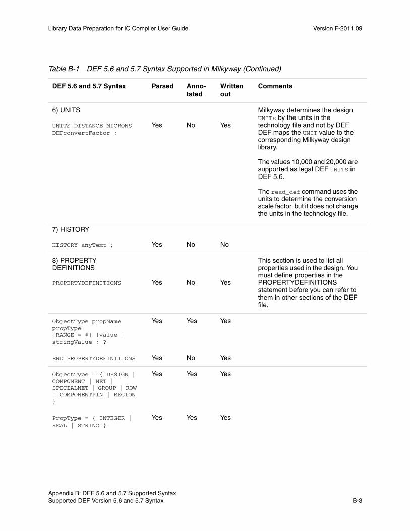
Library Data Preparation for IC Compiler User Guide Version F-2011.09
6) UNITS UNITS DISTANCE MICRONS DEFconvertFactor ;
Yes
No
Yes
Milkyway determines the design UNITs by the units in the technology file and not by DEF. DEF maps the UNIT value to the corresponding Milkyway design library. The values 10,000 and 20,000 are supported as legal DEF UNITS in DEF 5.6. The read_def command uses the units to determine the conversion scale factor, but it does not change the units in the technology file.
7) HISTORY HISTORY anyText ;
Yes
No
No
8) PROPERTY DEFINITIONS PROPERTYDEFINITIONS
Yes
No
Yes
This section is used to list all properties used in the design. You must define properties in the PROPERTYDEFINITIONS statement before you can refer to them in other sections of the DEF file.
ObjectType propName propType [RANGE # #] [value | stringValue ; ?
Yes Yes Yes
END PROPERTYDEFINITIONS Yes No Yes
ObjectType = { DESIGN | COMPONENT | NET | SPECIALNET | GROUP | ROW | COMPONENTPIN | REGION }
Yes Yes Yes
PropType = { INTEGER | REAL | STRING }
Yes Yes Yes
Table B-1 DEF 5.6 and 5.7 Syntax Supported in Milkyway (Continued)
DEF 5.6 and 5.7 Syntax Parsed Anno-tated
Written out
Comments
Chapter B: DEF 5.6 and 5.7 Supported Syntax Supported DEF Version 5.6 and 5.7 Syntax B-3Appendix B: DEF 5.6 and 5.7 Supported Syntax Supported DEF Version 5.6 and 5.7 Syntax B-3
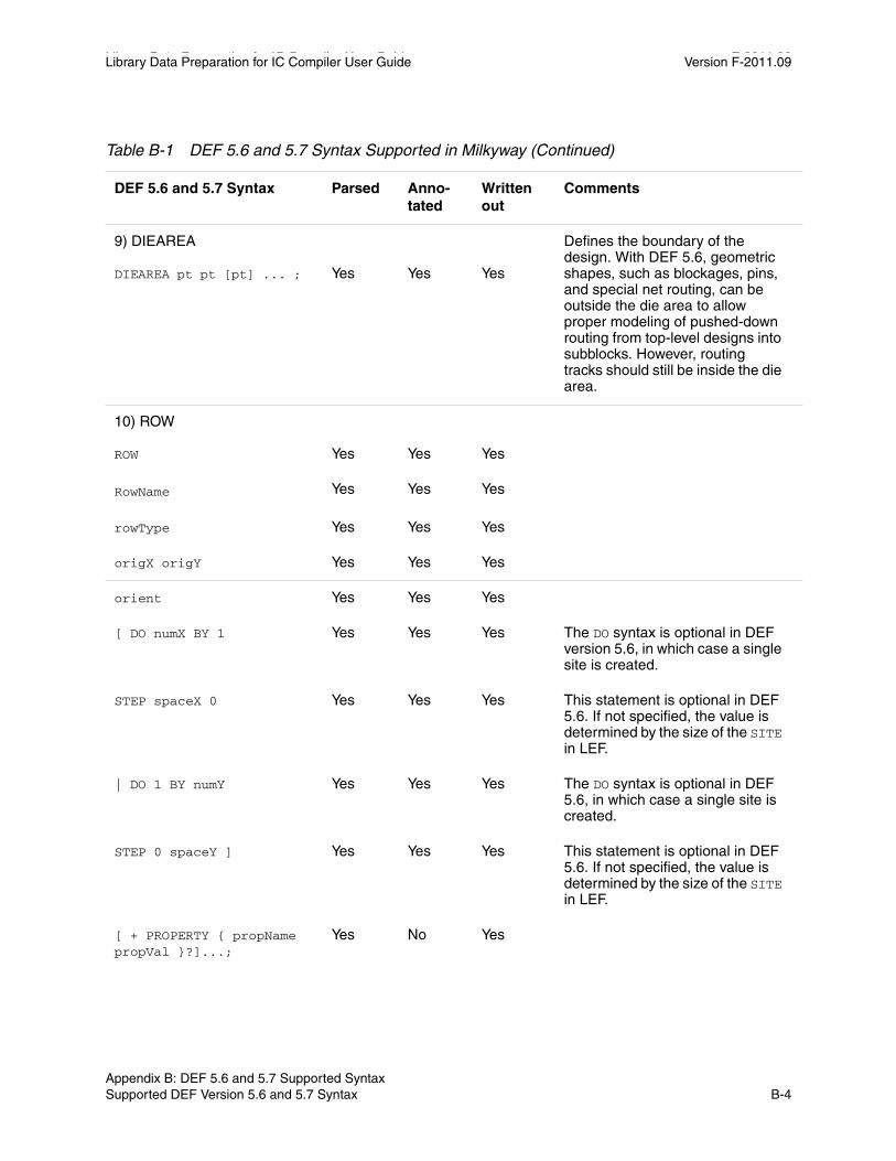
Library Data Preparation for IC Compiler User Guide F-2011.09Library Data Preparation for IC Compiler User Guide Version F-2011.09
9) DIEAREA DIEAREA pt pt [pt] ... ;
Yes
Yes
Yes
Defines the boundary of the design. With DEF 5.6, geometric shapes, such as blockages, pins, and special net routing, can be outside the die area to allow proper modeling of pushed-down routing from top-level designs into subblocks. However, routing tracks should still be inside the die area.
10) ROW ROW
Yes
Yes
Yes
RowName Yes Yes Yes
rowType Yes Yes Yes
origX origY Yes Yes Yes
orient Yes Yes Yes
[ DO numX BY 1 Yes Yes Yes The DO syntax is optional in DEF version 5.6, in which case a single site is created.
STEP spaceX 0 Yes Yes Yes This statement is optional in DEF 5.6. If not specified, the value is determined by the size of the SITE in LEF.
| DO 1 BY numY Yes Yes Yes The DO syntax is optional in DEF 5.6, in which case a single site is created.
STEP 0 spaceY ] Yes Yes Yes This statement is optional in DEF 5.6. If not specified, the value is determined by the size of the SITE in LEF.
[ + PROPERTY { propName propVal }?]...;
Yes No Yes
Table B-1 DEF 5.6 and 5.7 Syntax Supported in Milkyway (Continued)
DEF 5.6 and 5.7 Syntax Parsed Anno-tated
Written out
Comments
Appendix B: DEF 5.6 and 5.7 Supported Syntax Supported DEF Version 5.6 and 5.7 Syntax B-4
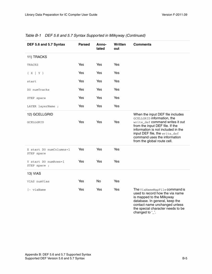
Library Data Preparation for IC Compiler User Guide Version F-2011.09
11) TRACKS TRACKS
Yes
Yes
Yes
{ X | Y } Yes Yes Yes
start Yes Yes Yes
DO numTracks Yes Yes Yes
STEP space Yes Yes Yes
LAYER layerName ; Yes Yes Yes
12) GCELLGRID GCELLGRID
Yes
Yes
Yes
When the input DEF file includes GCELLGRID information, the write_def command writes it out from the input DEF file. If the information is not included in the input DEF file, the write_def command uses the information from the global route cell.
X start DO numColumns+1 STEP space
Yes Yes Yes
Y start DO numRows+1 STEP space ;
Yes Yes Yes
13) VIAS VIAS numVias
Yes
No
Yes
[- viaName Yes Yes Yes The ViaNameMapFile command is used to record how the via name is mapped to the Milkyway database. In general, keep the contact name unchanged unless the special character needs to be changed to ‘_’.
Table B-1 DEF 5.6 and 5.7 Syntax Supported in Milkyway (Continued)
DEF 5.6 and 5.7 Syntax Parsed Anno-tated
Written out
Comments
Chapter B: DEF 5.6 and 5.7 Supported Syntax Supported DEF Version 5.6 and 5.7 Syntax B-5Appendix B: DEF 5.6 and 5.7 Supported Syntax Supported DEF Version 5.6 and 5.7 Syntax B-5
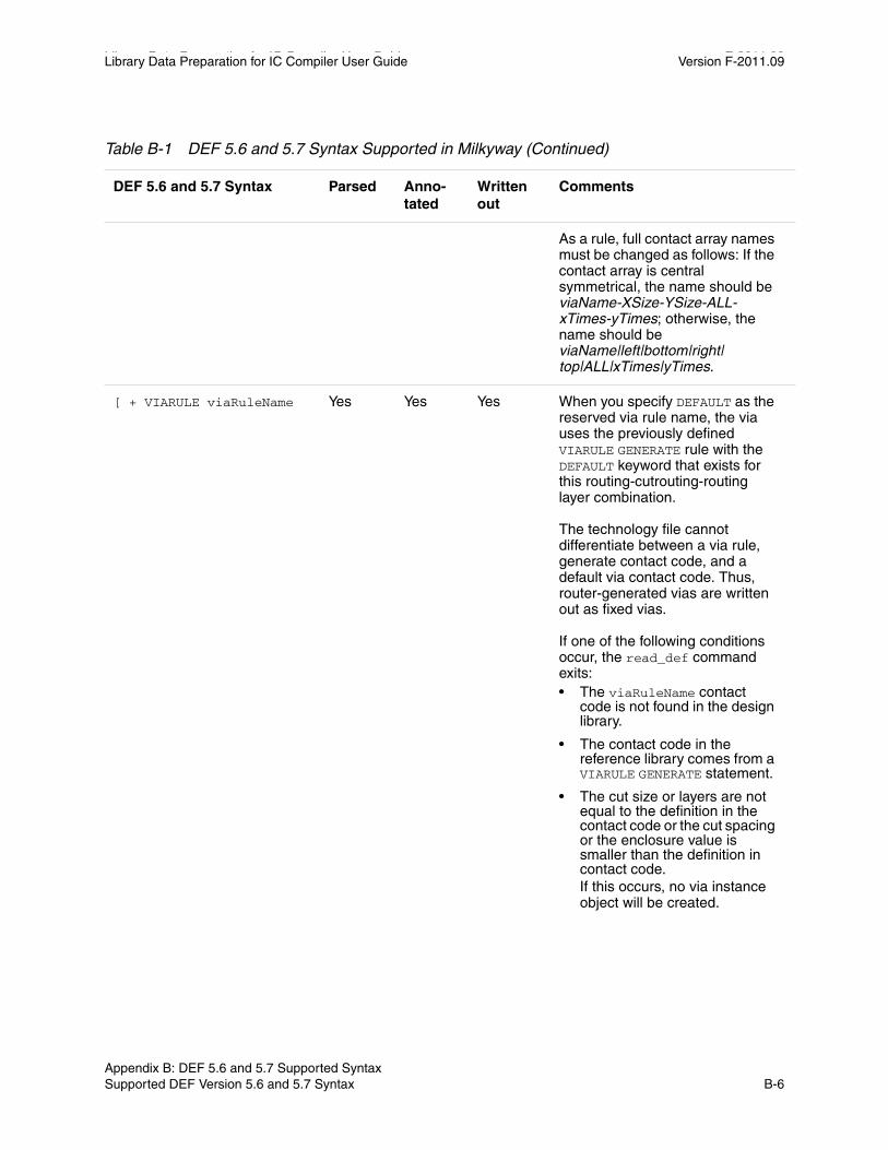
Library Data Preparation for IC Compiler User Guide F-2011.09Library Data Preparation for IC Compiler User Guide Version F-2011.09
As a rule, full contact array names must be changed as follows: If the contact array is central symmetrical, the name should be viaName-XSize-YSize-ALL-xTimes-yTimes; otherwise, the name should be viaName|left|bottom|right| top|ALL|xTimes|yTimes.
[ + VIARULE viaRuleName Yes Yes Yes When you specify DEFAULT as the reserved via rule name, the via uses the previously defined VIARULE GENERATE rule with the DEFAULT keyword that exists for this routing-cutrouting-routing layer combination. The technology file cannot differentiate between a via rule, generate contact code, and a default via contact code. Thus, router-generated vias are written out as fixed vias. If one of the following conditions occur, the read_def command exits:• The viaRuleName contact
code is not found in the design library.
• The contact code in the reference library comes from a VIARULE GENERATE statement.
• The cut size or layers are not equal to the definition in the contact code or the cut spacing or the enclosure value is smaller than the definition in contact code.If this occurs, no via instance object will be created.
Table B-1 DEF 5.6 and 5.7 Syntax Supported in Milkyway (Continued)
DEF 5.6 and 5.7 Syntax Parsed Anno-tated
Written out
Comments
Appendix B: DEF 5.6 and 5.7 Supported Syntax Supported DEF Version 5.6 and 5.7 Syntax B-6

Library Data Preparation for IC Compiler User Guide Version F-2011.09
+ CUTSIZE xSize ySize Yes Yes Yes If the cut size is not equal to the definition in the contact code, the read_def command quits with an error.
+ LAYERS botmetalLayer cutLayer topMetalLayer
Yes Yes Yes If the layers are not equal to the definition in the contact code, the read_def command quits with an error.
+ CUTSPACING xCutSpacing yCutSpacing
Yes Yes Yes If the cut spacing is smaller than the definition in the contact code, the read_def command quits with an error.
+ ENCLOSURE xBotEnc yBotEnc xTopEnc yTopEnc
Yes Yes Yes If the enclosure value is smaller than the definition in the contact code, the read_def command quits with an error.
[+ ROWCOL numCutRows NumCutCols]
Yes Yes Yes
[+ ORIGIN xOffset yOffset]
Yes Yes Yes
[+ OFFSET xBotOffset yBotOffset xTopOffset yTopOffset]
Yes Yes Yes
[+ PATTERN cutPattern] ] Yes Yes Yes
| [ + RECT layerName pt pt
Yes Yes Yes
| + POLYGON layerName pt pt pt] ...];
Yes No No
END VIAS Yes No Yes
14) Styles [Styles
Yes
No
No
This section is currently not supported.
Table B-1 DEF 5.6 and 5.7 Syntax Supported in Milkyway (Continued)
DEF 5.6 and 5.7 Syntax Parsed Anno-tated
Written out
Comments
Chapter B: DEF 5.6 and 5.7 Supported Syntax Supported DEF Version 5.6 and 5.7 Syntax B-7Appendix B: DEF 5.6 and 5.7 Supported Syntax Supported DEF Version 5.6 and 5.7 Syntax B-7

Library Data Preparation for IC Compiler User Guide F-2011.09Library Data Preparation for IC Compiler User Guide Version F-2011.09
numStyles ; Yes No No
{- STYLE styleNum pt pt pt ... ;} ...
Yes No No
END STYLES] Yes No No
15) NONDEFAULTRULES NONDEFAULTRULES numRules ;
Yes
No
Yes
{- ruleName Yes Yes Yes
[+ HARDSPACING] Yes Yes No DEF 5.6 syntax. Specifies that the routing spacing requires hard rules, which implies that routers treat extra spacing requirements as violations.
{+ LAYER layerName Yes Yes Yes
WIDTH minWidth Yes Yes Yes
[DIAGWIDTH diagWidth] Yes No No If used in DEF nondefault rule definitions, the read_def command produces a warning message and the write_def command cannot write it out.
[SPACING minSpacing] Yes Yes Yes
[WIREEXT wireExt]} ... Yes Yes Yes
[+ VIA viaName] ... Yes Yes Yes
[+ VIARULE viaRuleName] ...
Yes Yes Yes
[+ MINCUTS cutLayerName numCuts] ...
Yes No No If used in DEF nondefault rule definitions, the read_def command produces a warning message and the write_def command cannot write it out.
Table B-1 DEF 5.6 and 5.7 Syntax Supported in Milkyway (Continued)
DEF 5.6 and 5.7 Syntax Parsed Anno-tated
Written out
Comments
Appendix B: DEF 5.6 and 5.7 Supported Syntax Supported DEF Version 5.6 and 5.7 Syntax B-8
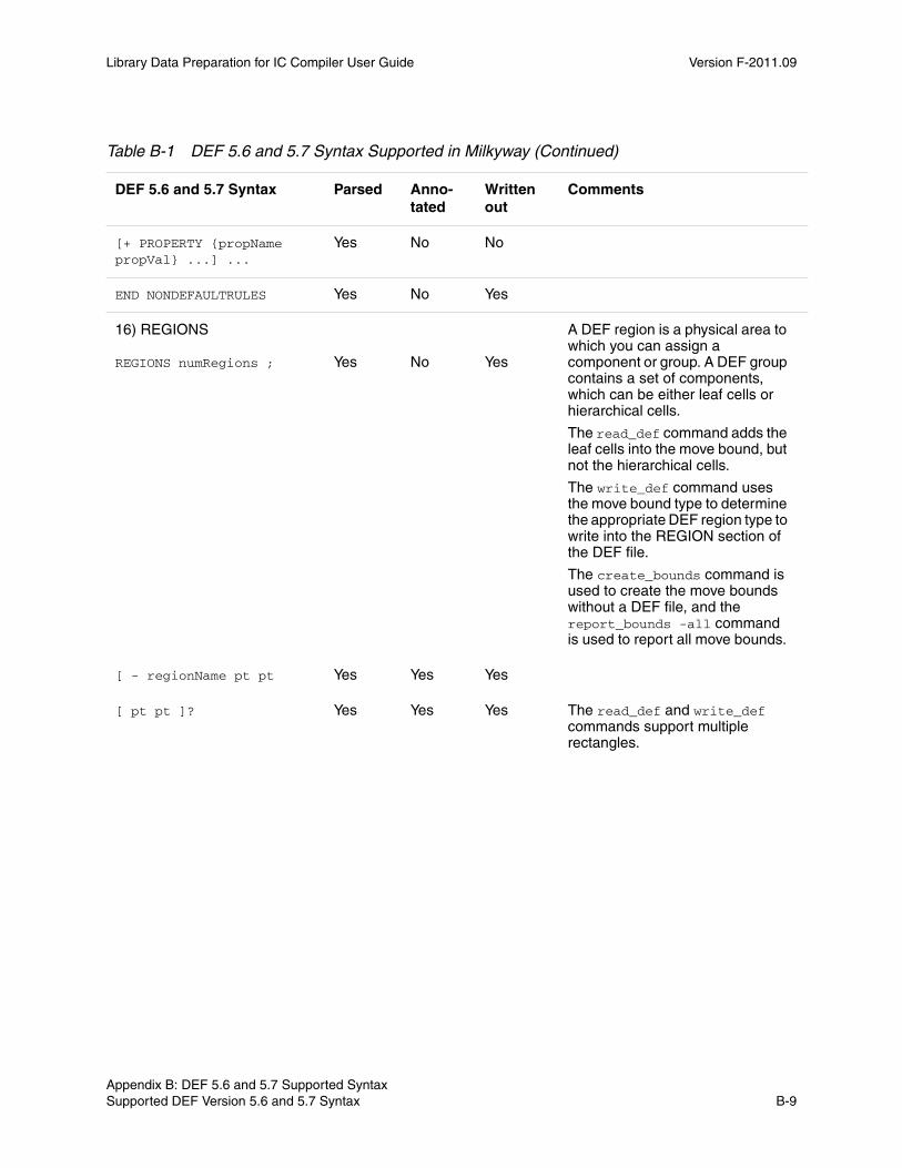
Library Data Preparation for IC Compiler User Guide Version F-2011.09
[+ PROPERTY {propName propVal} ...] ...
Yes No No
END NONDEFAULTRULES Yes No Yes
16) REGIONS REGIONS numRegions ;
Yes
No
Yes
A DEF region is a physical area to which you can assign a component or group. A DEF group contains a set of components, which can be either leaf cells or hierarchical cells.
The read_def command adds the leaf cells into the move bound, but not the hierarchical cells.
The write_def command uses the move bound type to determine the appropriate DEF region type to write into the REGION section of the DEF file.
The create_bounds command is used to create the move bounds without a DEF file, and the report_bounds -all command is used to report all move bounds.
[ - regionName pt pt Yes Yes Yes
[ pt pt ]? Yes Yes Yes The read_def and write_def commands support multiple rectangles.
Table B-1 DEF 5.6 and 5.7 Syntax Supported in Milkyway (Continued)
DEF 5.6 and 5.7 Syntax Parsed Anno-tated
Written out
Comments
Chapter B: DEF 5.6 and 5.7 Supported Syntax Supported DEF Version 5.6 and 5.7 Syntax B-9Appendix B: DEF 5.6 and 5.7 Supported Syntax Supported DEF Version 5.6 and 5.7 Syntax B-9

Library Data Preparation for IC Compiler User Guide F-2011.09Library Data Preparation for IC Compiler User Guide Version F-2011.09
+ TYPE { FENCE | GUIDE } Yes Yes Yes Default - All instances assigned to the region are placed inside the region boundaries, and other cells are also allowed inside the region. It is a hard move bound.
FENCE - All instances assigned to this type of region must be exclusively placed inside the region boundaries. No other instances are allowed inside this region. It is an exclusive move bound.
GUIDE - All instances assigned to this type of region should be placed inside this region. It’s a soft move bound.
[ + PROPERTY { propName propVal }... ]... ; ]?
Yes Yes Yes
END REGIONS Yes No Yes
17) COMPONENTS COMPONENTS numComps ;
Yes
No
Yes
[ - compName modelName Yes Yes Yes
[ + EEQMASTER macroname ]
Yes Yes Yes
[ + SOURCE NETLIST | DIST | USER | TIMING ] ]
Yes Yes Yes
[+ {FIXED pt orient | COVER pt orient | PLACED pt
orient
| UNPLACED} ]
Yes Yes Yes
Table B-1 DEF 5.6 and 5.7 Syntax Supported in Milkyway (Continued)
DEF 5.6 and 5.7 Syntax Parsed Anno-tated
Written out
Comments
Appendix B: DEF 5.6 and 5.7 Supported Syntax Supported DEF Version 5.6 and 5.7 Syntax B-10
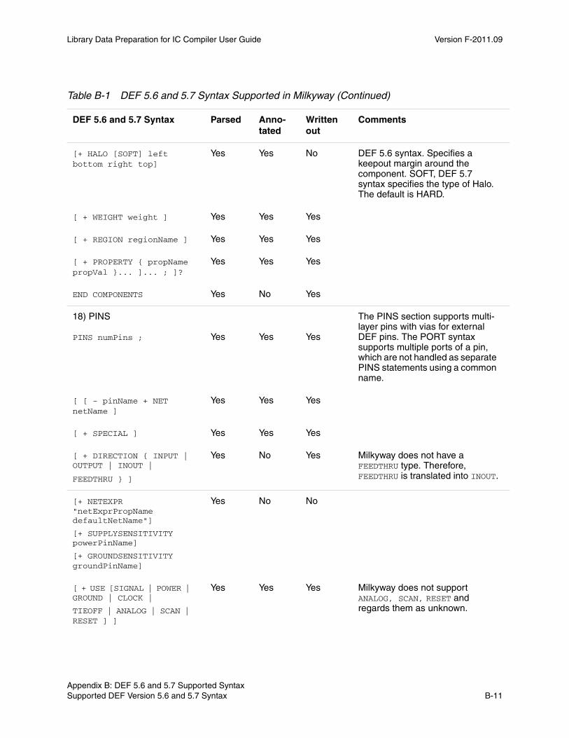
Library Data Preparation for IC Compiler User Guide Version F-2011.09
[+ HALO [SOFT] left bottom right top]
Yes Yes No DEF 5.6 syntax. Specifies a keepout margin around the component. SOFT, DEF 5.7 syntax specifies the type of Halo. The default is HARD.
[ + WEIGHT weight ] Yes Yes Yes
[ + REGION regionName ] Yes Yes Yes
[ + PROPERTY { propName propVal }... ]... ; ]?
Yes Yes Yes
END COMPONENTS Yes No Yes
18) PINS PINS numPins ;
Yes
Yes
Yes
The PINS section supports multi-layer pins with vias for external DEF pins. The PORT syntax supports multiple ports of a pin, which are not handled as separate PINS statements using a common name.
[ [ - pinName + NET netName ]
Yes Yes Yes
[ + SPECIAL ] Yes Yes Yes
[ + DIRECTION { INPUT | OUTPUT | INOUT |
FEEDTHRU } ]
Yes No Yes Milkyway does not have a FEEDTHRU type. Therefore, FEEDTHRU is translated into INOUT.
[+ NETEXPR "netExprPropName defaultNetName"]
[+ SUPPLYSENSITIVITY powerPinName]
[+ GROUNDSENSITIVITY groundPinName]
Yes No No
[ + USE [SIGNAL | POWER | GROUND | CLOCK |
TIEOFF | ANALOG | SCAN | RESET ] ]
Yes Yes Yes Milkyway does not support ANALOG, SCAN, RESET and regards them as unknown.
Table B-1 DEF 5.6 and 5.7 Syntax Supported in Milkyway (Continued)
DEF 5.6 and 5.7 Syntax Parsed Anno-tated
Written out
Comments
Chapter B: DEF 5.6 and 5.7 Supported Syntax Supported DEF Version 5.6 and 5.7 Syntax B-11Appendix B: DEF 5.6 and 5.7 Supported Syntax Supported DEF Version 5.6 and 5.7 Syntax B-11

Library Data Preparation for IC Compiler User Guide F-2011.09Library Data Preparation for IC Compiler User Guide Version F-2011.09
<antenna rules> Yes Yes Yes
[[+PORT] Yes Yes Yes
[ + LAYER layerName pt pt
| + POLYGON layerName
pt pt pt | + VIA viaName pt ...] ...
[ + { FIXED | PLACED | COVER } pt orient ]
Yes Yes Yes pinName is used to set nameId. Polygon-shaped pins are supported in DEF 5.6 and 5.7.
[SPACING minSpacing | DESIGNRULEWIDTH
effectiveWidth
Yes No No
END PINS Yes No Yes
19) PINPROPERTIES PINPROPERTIES num ;
Yes
No
Yes
[- {compName pinName | PIN pinName}
Yes Yes Yes
[ + PROPERTY { propName propVal }... ]... ; ]…
Yes Yes Yes
END PINPROPERTIES Yes No Yes
20) BLOCKAGES Blockage numblockages ;
Yes
No
Yes
- LAYER LayerName Yes Yes Yes Used for route guide. Due to DEF syntax limitation, DEF files cannot distinguish preroute route guides from signal route guides. Therefore, the write_def command does not output preroute route guides.
+ COMPONENT CompName Yes Yes Yes read_def annotates BLOCKAGE + COMPONENT as the keepout margin in the Milkyway database.
Table B-1 DEF 5.6 and 5.7 Syntax Supported in Milkyway (Continued)
DEF 5.6 and 5.7 Syntax Parsed Anno-tated
Written out
Comments
Appendix B: DEF 5.6 and 5.7 Supported Syntax Supported DEF Version 5.6 and 5.7 Syntax B-12
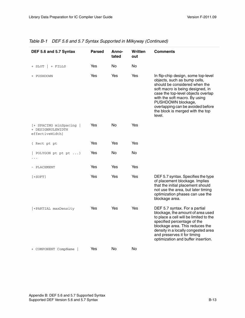
Library Data Preparation for IC Compiler User Guide Version F-2011.09
+ SLOT | + FILLS Yes No No
+ PUSHDOWN Yes Yes Yes In flip-chip design, some top-level objects, such as bump cells, should be considered when the soft macro is being designed, in case the top-level objects overlap with the soft macro. By using PUSHDOWN blockage, overlapping can be avoided before the block is merged with the top level.
[+ SPACING minSpacing | + DESIGNRULEWIDTH effectiveWidth]
Yes No Yes
{ Rect pt pt Yes Yes Yes
| POLYGON pt pt pt ...} ...
Yes No No
- PLACEMENT Yes Yes Yes
[+SOFT] Yes Yes Yes DEF 5.7 syntax. Specifies the type of placement blockage. Implies that the initial placement should not use the area, but later timing optimization phases can use the blockage area.
|+PARTIAL maxDensity Yes Yes Yes DEF 5.7 syntax. For a partial blockage, the amount of area used to place a cell will be limited to the specified percentage of the blockage area. This reduces the density in a locally congested area and preserves it for timing optimization and buffer insertion.
+ COMPONENT CompName | Yes No No
Table B-1 DEF 5.6 and 5.7 Syntax Supported in Milkyway (Continued)
DEF 5.6 and 5.7 Syntax Parsed Anno-tated
Written out
Comments
Chapter B: DEF 5.6 and 5.7 Supported Syntax Supported DEF Version 5.6 and 5.7 Syntax B-13Appendix B: DEF 5.6 and 5.7 Supported Syntax Supported DEF Version 5.6 and 5.7 Syntax B-13
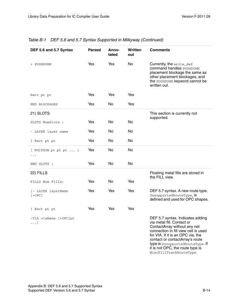
Library Data Preparation for IC Compiler User Guide F-2011.09Library Data Preparation for IC Compiler User Guide Version F-2011.09
+ PUSHDOWN Yes Yes No Currently, the write_def command handles PUSHDOWN placement blockage the same as other placement blockages, and the PUSHDOWN keyword cannot be written out.
Rect pt pt Yes Yes Yes
END BLOCKAGES Yes No Yes
21) SLOTS SLOTS NumSlots ;
Yes
No
No
This section is currently not supported.
- LAYER layer name Yes No No
{ Rect pt pt Yes No No
| POLYGON pt pt pt ... } ...
Yes No No
END SLOTS ; Yes No No
22) FILLS FILLS Num Fills;
Yes
No
Yes
Floating metal fills are stored in the FILL view.
[- LAYER layerName [+OPC]
Yes Yes Yes DEF 5.7 syntax. A new route type, UnsupportedRouteType, is defined and used for OPC shapes.
{ Rect pt pt Yes Yes Yes
-VIA viaName [+OPC]pt ...]
DEF 5.7 syntax. Indicates adding via metal fill. Contact or ContactArray without any net connection in fill view cell is used for VIA. If it is an OPC via, the contact or contactArray’s route type is UnsupportedRouteType. If it is not OPC, the route type is MiscFillTrackRouteType.
Table B-1 DEF 5.6 and 5.7 Syntax Supported in Milkyway (Continued)
DEF 5.6 and 5.7 Syntax Parsed Anno-tated
Written out
Comments
Appendix B: DEF 5.6 and 5.7 Supported Syntax Supported DEF Version 5.6 and 5.7 Syntax B-14
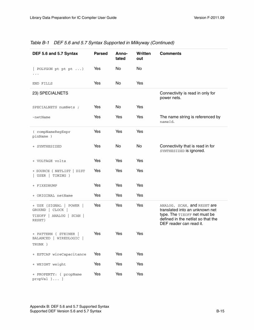
Library Data Preparation for IC Compiler User Guide Version F-2011.09
| POLYGON pt pt pt ...} ...
Yes No No
END FILLS Yes No Yes
23) SPECIALNETS SPECIALNETS numNets ;
Yes
No
Yes
Connectivity is read in only for power nets.
-netName Yes Yes Yes The name string is referenced by nameId.
( compNameRegExpr pinName )
Yes Yes Yes
+ SYNTHESIZED Yes No No Connectivity that is read in for SYNTHESIZED is ignored.
+ VOLTAGE volts Yes Yes Yes
+ SOURCE { NETLIST | DIST | USER | TIMING }
Yes Yes Yes
+ FIXEDBUMP Yes Yes Yes
+ ORIGINAL netName Yes Yes Yes
+ USE {SIGNAL | POWER | GROUND | CLOCK |
TIEOFF | ANALOG | SCAN | RESET}
Yes Yes Yes ANALOG, SCAN, and RESET are translated into an unknown net type. The TIEOFF net must be defined in the netlist so that the DEF reader can read it.
+ PATTERN { STEINER | BALANCED | WIREDLOGIC |
TRUNK }
Yes Yes Yes
+ ESTCAP wireCapacitance Yes Yes Yes
+ WEIGHT weight Yes Yes Yes
+ PROPERTY: { propName propVal }... ]
Yes Yes Yes
Table B-1 DEF 5.6 and 5.7 Syntax Supported in Milkyway (Continued)
DEF 5.6 and 5.7 Syntax Parsed Anno-tated
Written out
Comments
Chapter B: DEF 5.6 and 5.7 Supported Syntax Supported DEF Version 5.6 and 5.7 Syntax B-15Appendix B: DEF 5.6 and 5.7 Supported Syntax Supported DEF Version 5.6 and 5.7 Syntax B-15

Library Data Preparation for IC Compiler User Guide F-2011.09Library Data Preparation for IC Compiler User Guide Version F-2011.09
SPECIALWIRING Using the read_def -preserve_wire_ends command, all special net power and ground routes are created as paths with square ends; FILLWIRE routes are created as rectangles; all other routes are created as wires with half-width extension ends.
You should use this option when the DEF file is from a third party tool after the read_def command. Then, the read_def command can keep the wiring description exactly as described in the DEF. Also, there will not be any incorrect DRC violations and the flow will not be broken.
+ POLYGON layerName pt pt pt ...
Yes No No Milkyway does not support POLYGON. In DEF 5.6, 45-degree routing is described using the routingPoints option. Note: DEF 5.6 allows you to import and export 45-degree preroutes and polygon-shaped pins. However, DEF supports only nonextension and half-width extension 45-degree routing.
+ RECT layerName pt pt Yes No No
{+ COVER | + FIXED | +ROUTED}
Yes Yes Yes
+ SHIELD shieldNetName Yes Yes Yes
{ layerName routhWidth | NEW layerName routeWidth }
Yes Yes Yes
routingPoints x y [extValue]
Yes Yes Yes DEF 5.6 supports 45-degree routing in point-to-point style.
Table B-1 DEF 5.6 and 5.7 Syntax Supported in Milkyway (Continued)
DEF 5.6 and 5.7 Syntax Parsed Anno-tated
Written out
Comments
Appendix B: DEF 5.6 and 5.7 Supported Syntax Supported DEF Version 5.6 and 5.7 Syntax B-16
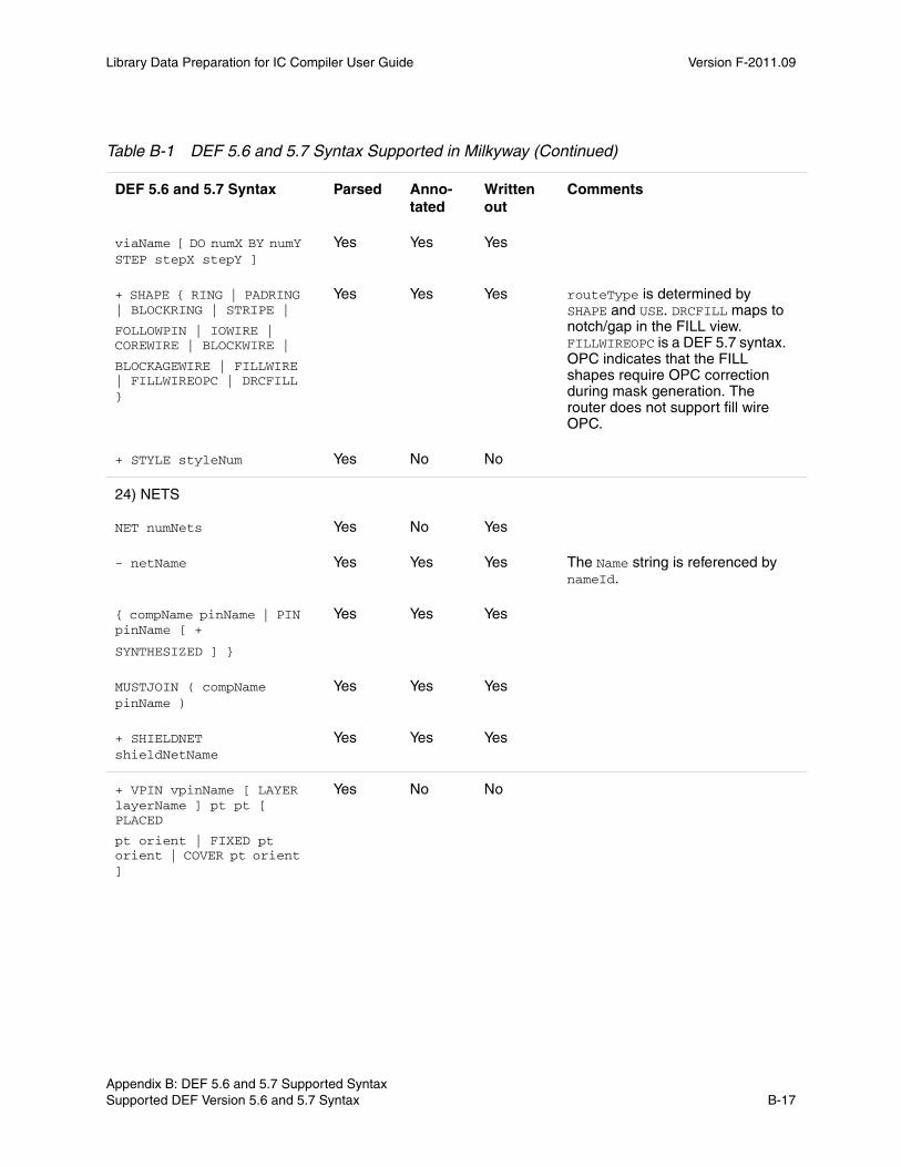
Library Data Preparation for IC Compiler User Guide Version F-2011.09
viaName [ DO numX BY numY STEP stepX stepY ]
Yes Yes Yes
+ SHAPE { RING | PADRING | BLOCKRING | STRIPE |
FOLLOWPIN | IOWIRE | COREWIRE | BLOCKWIRE |
BLOCKAGEWIRE | FILLWIRE | FILLWIREOPC | DRCFILL }
Yes Yes Yes routeType is determined by SHAPE and USE. DRCFILL maps to notch/gap in the FILL view. FILLWIREOPC is a DEF 5.7 syntax. OPC indicates that the FILL shapes require OPC correction during mask generation. The router does not support fill wire OPC.
+ STYLE styleNum Yes No No
24) NETS NET numNets
Yes
No
Yes
- netName Yes Yes Yes The Name string is referenced by nameId.
{ compName pinName | PIN pinName [ +
SYNTHESIZED ] }
Yes Yes Yes
MUSTJOIN ( compName pinName )
Yes Yes Yes
+ SHIELDNET shieldNetName
Yes Yes Yes
+ VPIN vpinName [ LAYER layerName ] pt pt [ PLACED
pt orient | FIXED pt orient | COVER pt orient ]
Yes No No
Table B-1 DEF 5.6 and 5.7 Syntax Supported in Milkyway (Continued)
DEF 5.6 and 5.7 Syntax Parsed Anno-tated
Written out
Comments
Chapter B: DEF 5.6 and 5.7 Supported Syntax Supported DEF Version 5.6 and 5.7 Syntax B-17Appendix B: DEF 5.6 and 5.7 Supported Syntax Supported DEF Version 5.6 and 5.7 Syntax B-17

Library Data Preparation for IC Compiler User Guide F-2011.09Library Data Preparation for IC Compiler User Guide Version F-2011.09
+ SUBNET subnetName [ ( { compName pinName | PIN
pinName | VPIN vpinName } ) ] [NONDEFAULTRULE
ruleName ] [ regularWiring ] …]
Yes No No
+ XTALK class Yes Yes Yes
+ NONDEFAULTRULE ruleName
Yes Yes Yes
+ SOURCE { DIST | NETLIST | TEST | TIMING | USER }
Yes No Yes
+ FIXEDBUMP Yes No Yes
+ FREQUENCY frequency Yes No Yes
+ ORIGINAL netName Yes No Yes
+ USE {ANALOG | CLOCK | GROUND | POWER |
RESET | SCAN | SIGNAL | TIEOFF }
Yes Yes Yes ANALOG, SCAN, and RESET are translated into an unknown net type. The TIEOFF net must be defined in the netlist so that the DEF reader can read it.
+ PATTERN {BALANCE | STEINER | TRUNK |
WIREDLOGIC }
Yes Yes Yes
+ ESTCAP wireCapacitance Yes Yes Yes
+ WEIGHT weight Yes Yes Yes
[ + PROPERTY: { propName propVal }... ]... ; ]?
Yes Yes Yes
REGULARWIRING
{+ COVER | + FIXED | + ROUTED | + NOSHIELD}
Yes Yes Yes The FIXED/COVER wiring route type is user-defined.
Table B-1 DEF 5.6 and 5.7 Syntax Supported in Milkyway (Continued)
DEF 5.6 and 5.7 Syntax Parsed Anno-tated
Written out
Comments
Appendix B: DEF 5.6 and 5.7 Supported Syntax Supported DEF Version 5.6 and 5.7 Syntax B-18
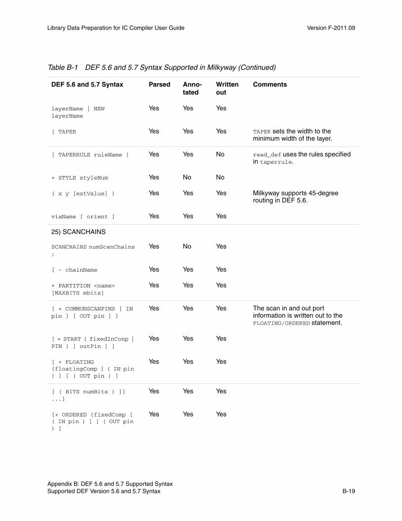
Library Data Preparation for IC Compiler User Guide Version F-2011.09
layerName | NEW layerName
Yes Yes Yes
[ TAPER Yes Yes Yes TAPER sets the width to the minimum width of the layer.
| TAPERRULE ruleName ] Yes Yes No read_def uses the rules specified in taperrule.
+ STYLE styleNum Yes No No
( x y [extValue] ) Yes Yes Yes Milkyway supports 45-degree routing in DEF 5.6.
viaName [ orient ] Yes Yes Yes
25) SCANCHAINS SCANCHAINS numScanChains ;
Yes
No
Yes
[ - chainName Yes Yes Yes
+ PARTITION <name> [MAXBITS mbits]
Yes Yes Yes
[ + COMMONSCANPINS [ IN pin ] [ OUT pin ] ]
Yes Yes Yes The scan in and out port information is written out to the FLOATING/ORDERED statement.
[ + START { fixedInConp | PIN } [ outPin ] ]
Yes Yes Yes
[ + FLOATING {floatingComp [ ( IN pin ) ] [ ( OUT pin ) ]
Yes Yes Yes
[ ( BITS numBits ) ]} ...]
Yes Yes Yes
[+ ORDERED {fixedComp [ ( IN pin ) ] [ ( OUT pin ) ]
Yes Yes Yes
Table B-1 DEF 5.6 and 5.7 Syntax Supported in Milkyway (Continued)
DEF 5.6 and 5.7 Syntax Parsed Anno-tated
Written out
Comments
Chapter B: DEF 5.6 and 5.7 Supported Syntax Supported DEF Version 5.6 and 5.7 Syntax B-19Appendix B: DEF 5.6 and 5.7 Supported Syntax Supported DEF Version 5.6 and 5.7 Syntax B-19
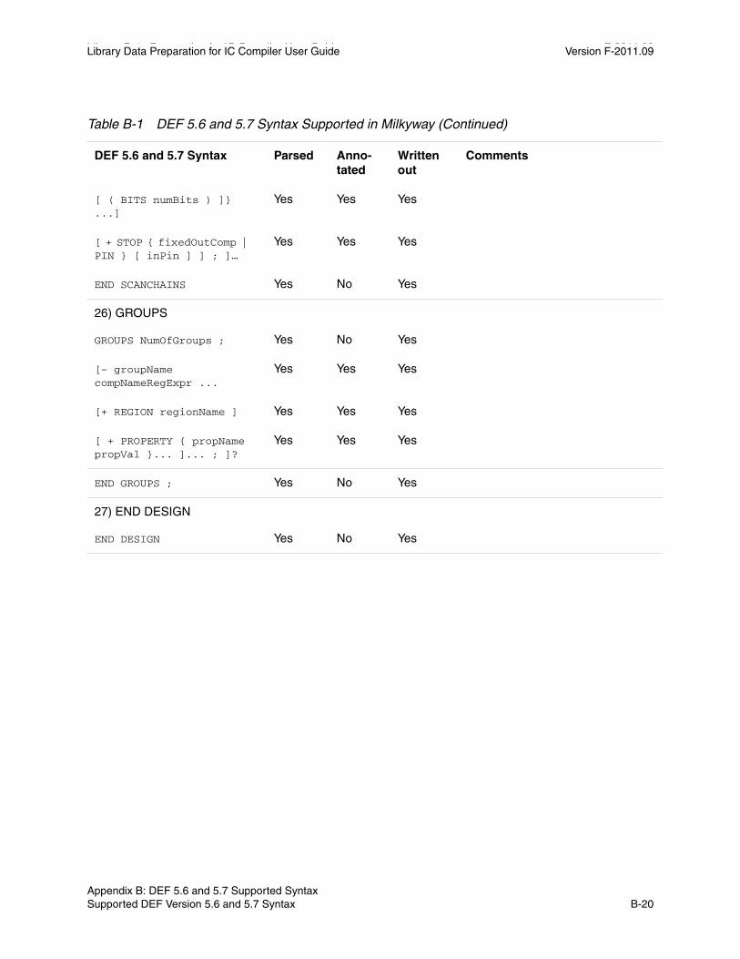
Library Data Preparation for IC Compiler User Guide F-2011.09Library Data Preparation for IC Compiler User Guide Version F-2011.09
[ ( BITS numBits ) ]} ...]
Yes Yes Yes
[ + STOP { fixedOutComp | PIN } [ inPin ] ] ; ]…
Yes Yes Yes
END SCANCHAINS Yes No Yes
26) GROUPS GROUPS NumOfGroups ;
Yes
No
Yes
[– groupName compNameRegExpr ...
Yes Yes Yes
[+ REGION regionName ] Yes Yes Yes
[ + PROPERTY { propName propVal }... ]... ; ]?
Yes Yes Yes
END GROUPS ; Yes No Yes
27) END DESIGN END DESIGN
Yes
No
Yes
Table B-1 DEF 5.6 and 5.7 Syntax Supported in Milkyway (Continued)
DEF 5.6 and 5.7 Syntax Parsed Anno-tated
Written out
Comments
Appendix B: DEF 5.6 and 5.7 Supported Syntax Supported DEF Version 5.6 and 5.7 Syntax B-20

Index
AALF format 6-13AMonitor A-2AServer A-2
Bback-bias pins 5-2blockage areas (BPV) 5-16blockage merging (BPV) 5-16blockage types (BPV) 5-8blockage, pin, and via extraction (BPV) 5-4boundary, multiple-height 5-23boundary, place-and-route 5-19BPV (blockage, pin, and via extraction) 1-3, 5-4
blockage areas 5-16blockage types 5-8Cell Library > Set PR Boundary command
5-20Check Wire Track dialog box 5-27Define Wire Track dialog box 5-26diagram 5-5extract pin by text options 5-9horizontal via placement 5-18IC Compiler commands 5-5internal pin exclusion 5-19macro extract blockage options 5-12
macro extract pin by text options 5-14macro extract via options 5-15macros 5-12pin identification by text 5-15preserve system metal blockage 5-8real metal blockage 5-8route guides 5-8Set Multiple Height PR Boundary dialog box
5-23Set PR Boundary dialog box 5-22standard cells and pad cells 5-6system metal blockage 5-8text fall through options 5-16thin wire rules 5-8Verti Via Grid Offset 5-18via extraction options 5-11Wire Tracks > Check Pin on Track command
5-27Wire Tracks > Define Unit Tile Wire Tracks
command 5-25Browse Cell dialog box 2-5Browse Library dialog box 2-4
CCEL view 1-3
revision number 2-6title bar 2-6versus FRAM view 1-3
IN-1 IN-1

Library Data Preparation for IC Compiler User Guide Version F-2011.09
cellclosing 2-7closing in IC Compiler 7-12opening 2-5opening in IC Compiler 7-8saving in IC Compiler 7-11
Cell > Close command 2-7Cell > Make Macro Abstract command 5-12Cell > Open command 2-5Cell Library > Blockage, Pin & Via command
5-6Cell Library > LEF In 4-4Cell Library > Multi Height Cell command 5-23Cell Library > Set PR Boundary command 5-20Cell Library > Smash command 5-3cell types 1-3cell view window 2-6cells 1-2
copying in IC Compiler 7-14creating in IC Compiler 7-14flattening hierarchical 5-3
cell-type definition file, GDSII or OASIS 3-3Check Wire Track dialog box 5-27check_library command 6-1
cell group 6-6in Library Compiler 6-2in Milkyway Environment 6-2library group 6-6logic libraries 6-5overview 6-2overview diagram 6-3physical libraries 6-9pin and pg_pin groups 6-6report examples 6-14set_check_library_options command 6-4syntax 6-2
Close Library dialog box 7-8close_mw_cel command 7-12close_mw_lib command 7-7commands
Cell > Make Macro Abstract 5-12Cell > Open 2-5Cell Library > Blockage, Pin & Via 5-6Cell Library > LEF in 4-4Cell Library > Multi Height Cell command
5-23Cell Library > Stream In 3-2check_library 6-1close_mw_cel 7-12close_mw_lib 7-7convert_mw_lib 7-18copy_mw_cel 7-14copy_mw_lib 7-13create_macro_fram 5-5create_mw_cel 7-14create_mw_lib 7-12current_mw_cel 7-10extract_blockage_pin_via 5-5File > Close Library 7-8File > Copy Design 7-14File > Create Library 7-13File > Export > Write Stream 7-17File > Open Design 7-9File > Open Library 7-7File > Save Design 7-11File > Set Library Reference 7-5flatten_cell 5-4Library > Create 2-15Library > Open 2-4open_mw_cel 2-9, 7-8open_mw_lib 2-8, 7-6Output > LEF Out 4-10Output > Stream Out 3-7printvar 2-11read_def 4-13read_gds 3-3, 4-6read_oasis 3-13report_mw_lib 7-5save_mw_cel 7-11set_app_var 2-11set_attribute 5-2set_check_library_options 6-4
IN-2 Index IN-2
Library Data Preparation for IC Compiler User Guide Version F-2011.09
set_local_link_library 1-4set_mw_lib_reference 7-4set_write_stream_options 7-15, 7-16split_mw_lib 7-15Wire Tracks > Check Pin on Track 5-27Wire Tracks > Define Unit Tile Wire Tracks
5-25write_def 4-15write_gds 3-8write_lef 4-11write_mw_lib_files 7-6write_oasis 3-15write_stream 7-16
CONN view 1-3conventions for documentation xiconvert_mw_lib command 7-18Copy Design dialog box 7-14copy_mw_cel command 7-14copy_mw_lib command 7-13Create Library dialog box 2-15, 7-13create_macro_fram command 5-5create_mw_cel command 7-14create_mw_lib command 7-12current_mw_cel command 7-10customer support xii
D.db libraries 1-4DEF 4-11
exporting 4-13import and export flow 4-16importing 4-11read_def command 4-13recommended flows 4-15syntax versions 5.6 and 5.7 B-2Verilog and DEF input flow 4-17write_def command 4-15
Define Wire Track dialog box 5-26design library, Milkyway 7-2
design versus reference libraries 7-2
Eelectromigration constraints
ALF format 6-13plib format 6-13
ERR view 1-3external_pin_file variable 5-19Extract Blockage dialog box 5-6extract_blockage_pin_via command 5-5
FFile > Close Library command 7-8File > Copy Design command 7-14File > Create Library command 7-13File > Export > Write Stream command 7-17File > Open Design command 7-9File > Open Library command 7-7File > Save Design command 7-11File > Set Library Reference command 7-5FILL view 1-3flatten hierarchical cells 5-3flatten_cell command 5-4FRAM view 1-3
creation (BPV) 5-4versus CEL view 1-3
GGDSII 3-1
cell-type definition file 3-3GDSII to Milkyway 3-2layer mapping file, stream in 3-5layer mapping file, stream out 3-9objects that can be streamed out 3-8writing from IC Compiler 7-15, 7-16
ground ports 5-2
IN-3 Index IN-3
Library Data Preparation for IC Compiler User Guide Version F-2011.09
Hhierarchical cells, flattening 5-3hierarchy separator 2-15horizontal via placement (BPV) 5-18HSPICE 1-5
IIC Compiler
check_library command 6-2Close Library dialog box 7-8close_mw_cel command 7-12close_mw_lib command 7-7convert_mw_lib command 7-18Copy Design dialog box 7-14copy_mw_cel command 7-14copy_mw_lib command 7-13Create Library dialog box 7-13create_macro_fram command 5-5create_mw_cel command 7-14create_mw_lib command 7-12creating new Milkyway cells 7-12creating new Milkyway libraries 7-12current_mw_cel command 7-10extract_blockage_pin_via command 5-5File > Close Library command 7-8File > Copy Design command 7-14File > Create Library command 7-13File > Export > Write Stream command 7-17File > Open Design command 7-9File > Open Library command 7-7File > Save Design command 7-11libraries used 1-2library editing commands 1-7Milkyway database commands 1-7Open Design dialog box 7-9Open Library dialog box 7-7open_mw_cel command 7-8open_mw_lib command 7-6opening and closing Milkyway cells 7-8opening and closing Milkyway libraries 7-6
reference control file 7-6report_mw_lib command 7-5Save Design dialog box 7-11save_mw_cel command 7-11Set Library Reference dialog box 7-5set_mw_lib_reference command 7-4split_mw_lib command 7-15using Milkyway libraries 7-1Write Stream dialog box 7-17write_mw_lib_files command 7-6writing GDSII 7-15, 7-16
IC Compiler writing OASIS 7-15, 7-16ILM view 1-3internal pin exclusion (BPV) 5-19introduction to library data preparation 1-1
Llayer mapping file, GDSII or OASIS stream in
3-5layer mapping file, GDSII or OASIS stream out
3-9layer mapping file, LEF in 4-8LEF to Milkyway 4-2
advanced (manual) LEF input flow 4-6automated LEF input flow 4-4flow diagram 4-3mixed input, LEF, GDSII, TF, CLF, PLIB 4-9
lef_layer_tf_number_mapper.pl script 4-8LEF/DEF
DEF syntax versions 5.6 and 5.7 B-2design exchange format (DEF) 4-11exporting DEF 4-13importing DEF 4-11introduction 4-2layer mapping file, LEF in 4-8LEF to Milkyway 4-2Milkyway to LEF 4-10Read Library flow 4-6read_def command 4-13recommended DEF flows 4-15
IN-4 Index IN-4

Library Data Preparation for IC Compiler User Guide Version F-2011.09
write_def command 4-15write_lef command 4-11
.lib libraries 1-4Liberty libraries 1-4Liberty NCX 1-5libraries
cell types 1-3cells 1-2closing in IC Compiler 7-7copying in IC Compiler 7-13creating in IC Compiler 7-12creating new 2-15.db 1-4design versus reference 7-2IC Compiler library editing commands 1-7in IC Compiler 1-2.lib 1-4Liberty 1-4logical 1-4Milkyway 1-2opening in IC Compiler 7-6physical versus logical 1-2reference (Milkyway) 7-2reference control file 7-6splitting in IC Compiler 7-15updating in IC Compiler 7-18
Library > Create command 2-15Library > Open command 2-4library cell preparation 5-1
blockage, pin, and via extraction 5-4flatten hierarchical cells 5-3FRAM view creation 5-4identify power and ground ports 5-2multiple-height boundary 5-23place-and-route boundary 5-19unit tile wire tracks 5-23wire tracks 5-23
library checking 6-1overview 6-2special checks 6-7specific checks 6-7
validating physical libraries 6-9Library Compiler 1-4, 1-5library data preparation
flow description 1-5flow diagram, detailed 2-14flow diagram, preparation and usage 1-6
library data preparation, introduction 1-1library preparation
GDSII 3-1LEF/DEF 4-1OASIS 3-1
link_library variable 1-4local_link_library attribute 1-4logic libraries, validating 6-5logical libraries 1-4logical versus physical libraries 1-2
MMake Macro dialog box 5-12man page command 2-9merging blockages (BPV) 5-16Milkyway
cell types 1-3database model version 7-18design library 7-2libraries 1-2library structure 7-2reference libraries 7-2updating database 7-18
Milkyway Environment 2-1, 2-10, 2-11BPV (blockage, pin, and via extraction) 5-4
diagram 5-6Browse Cell dialog box 2-5Browse Library dialog box 2-4Cell > Close command 2-7Cell > Open command 2-5Cell Library > Stream In command 3-2cell view window 2-6cell-type definition file 3-3command entry methods 2-3
IN-5 Index IN-5

Library Data Preparation for IC Compiler User Guide Version F-2011.09
Create Library dialog box 2-15flatten_cell command 5-4GDSII to Milkyway 3-2GUI command entry 2-3layer mapping file, LEF in 4-8layer mapping file, stream in 3-5layer mapping file, stream out 3-9LEF to Milkyway 4-2Library > Create command 2-15Library > Open command 2-4Milkyway to GDSII 3-7Milkyway to LEF 4-10Milkyway to OASIS 3-14OASIS to Milkyway 3-12objects that can be streamed out 3-8online help 2-12Open Cell dialog box 2-5Output > LEF Out command 4-10Output > Stream Out command 3-7overview 1-9read_def command 4-13read_gds command 3-3, 4-6read_oasis command 3-13Scheme command entry 2-11starting 2-2Stream In dialog box 3-2Stream Out Data File dialog box 3-7Tcl command entry 2-8Write LEF dialog box 4-10write_def command 4-15write_gds command 3-8write_lef command 4-11write_oasis command 3-15
Milkyway to GDSII 3-7Milkyway to LEF 4-10Milkyway to OASIS 3-14multiple-height boundary 5-23
Nnull display A-2
OOASIS 3-1
cell type definition file 3-3layer mapping file, stream in 3-5layer mapping file, stream out 3-9OASIS to Milkyway 3-12objects that can be streamed out 3-8writing from IC Compiler 7-15, 7-16
online help, Milkyway Environment 2-12Open Cell dialog box 2-5Open Design dialog box 7-9Open Library dialog box 7-7open_mw_cel command 2-9, 7-8open_mw_lib command 2-8, 7-6
Pphysical libraries 1-2physical versus logical libraries 1-2pin identification (BPV) 5-15PINASSIGN view 1-3place-and-route boundary 5-19port_type attribute 5-2ports, power and ground 5-2power ports 5-2preserve system metal blockage 5-8printvar command 2-11
RRead LEF dialog box 4-4read_def command 4-13read_gds command 3-3, 4-6read_oasis command 3-13real metal blockage (BPV) 5-8reference control file 7-6reference libraries, Milkyway 7-2
reference control file 7-6reporting 7-5
IN-6 Index IN-6
Library Data Preparation for IC Compiler User Guide Version F-2011.09
setting 7-4reference versus design libraries 7-2report_mw_lib command 7-5route guides (BPV) 5-8ROUTE view 1-3
SSave Design dialog box 7-11save_mw_cel command 7-11search_path variable 1-4server process A-2Set Library Reference dialog box 7-5Set Multiple Height PR Boundary dialog box
5-23Set PR Boundary dialog box 5-22set_app_var command 2-11set_attribute command 5-2set_check_library_options command 6-4, 6-5set_local_link_library command 1-4set_mw_lib_reference command 7-4set_write_stream_options command 7-15,
7-16Smash dialog box 5-3SMASH view 1-3SolvNet
accessing xiidocumentation xDownload Center x
split_mw_lib command 7-15Stream In dialog box 3-2Stream Out Data File dialog box 3-7system metal blockage (BPV) 5-8
Ttarget_library variable 1-4Tcl command entry 2-8
help 2-9
man page 2-9script execution 2-10source command 2-10variables 2-11
thin wire rules (BPV) 5-8
Uunit tile wire tracks 5-23updating data to latest Milkyway database
model version 7-18
Vvalidating logic libraries 6-5validating physical libraries 6-9variables
external_pin_file 5-19link_library 1-4search_path 1-4target_library 1-4
variables, Milkyway 2-11version, Milkyway 7-18Verti Via Grid Offset (BPV) 5-18via placement (BPV) 5-18view types 1-3
WWire Tracks > Check Pin on Track command
5-27Wire Tracks > Define Unit Tile Wire Tracks
command 5-25wire tracks, unit tile 5-23Write LEF dialog box 4-10Write Stream dialog box 7-17write_def command 4-15write_gds command 3-8write_lef command 4-11write_mw_lib_files command 7-6
IN-7 Index IN-7

Library Data Preparation for IC Compiler User Guide Version F-2011.09
write_oasis command 3-15 write_stream command 7-16
IN-8 Index IN-8