Embed Size (px)
Citation preview
https://support.industry.siemens.com/cs/ww/en/view/109479728
Library Description 01/2017
Library of General Functions (LGF) for S7-1200/1500 STEP 7 (TIA Portal)

Warranty and liability
LGF (Library of General Functions) Entry-ID: 109479728, V2.0.1, 01/2017 2
S
iem
en
s A
G 2
01
7 A
ll ri
gh
ts r
ese
rve
d
Warranty and liability
Note The Application Examples are not binding and do not claim to be complete regarding the circuits shown, equipping and any eventuality. The Application Examples do not represent customer-specific solutions. They are only intended to provide support for typical applications. You are responsible for ensuring that the described products are used correctly. These Application Examples do not relieve you of the responsibility to use safe practices in application, installation, operation and maintenance. When using these Application Examples, you recognize that we cannot be made liable for any damage/claims beyond the liability clause described. We reserve the right to make changes to these Application Examples at any time without prior notice. If there are any deviations between the recommendations provided in these Application Examples and other Siemens publications – e.g. Catalogs – the contents of the other documents have priority.
We do not accept any liability for the information contained in this document. Any claims against us – based on whatever legal reason – resulting from the use of the examples, information, programs, engineering and performance data etc., described in this Application Example shall be excluded. Such an exclusion shall not apply in the case of mandatory liability, e.g. under the German Product Liability Act (“Produkthaftungsgesetz”), in case of intent, gross negligence, or injury of life, body or health, guarantee for the quality of a product, fraudulent concealment of a deficiency or breach of a condition which goes to the root of the contract (“wesentliche Vertragspflichten”). The damages for a breach of a substantial contractual obligation are, however, limited to the foreseeable damage, typical for the type of contract, except in the event of intent or gross negligence or injury to life, body or health. The above provisions do not imply a change of the burden of proof to your detriment. Any form of duplication or distribution of these Application Examples or excerpts hereof is prohibited without the expressed consent of the Siemens AG.
Security informa-tion
Siemens provides products and solutions with industrial security functions that support the secure operation of plants, systems, machines and networks. In order to protect plants, systems, machines and networks against cyber threats, it is necessary to implement – and continuously maintain – a holistic, state-of-the-art industrial security concept. Siemens’ products and solutions only form one element of such a concept. Customer is responsible to prevent unauthorized access to its plants, systems, machines and networks. Systems, machines and components should only be connected to the enterprise network or the internet if and to the extent necessary and with appropriate security measures (e.g. use of firewalls and network segmentation) in place. Additionally, Siemens’ guidance on appropriate security measures should be taken into account. For more information about industrial security, please visit http://www.siemens.com/industrialsecurity.
Siemens’ products and solutions undergo continuous development to make them more secure. Siemens strongly recommends to apply product updates as soon as available and to always use the latest product versions. Use of product versions that are no longer supported, and failure to apply latest updates may increase customer’s exposure to cyber threats. To stay informed about product updates, subscribe to the Siemens Industrial Security RSS Feed under http://www.siemens.com/industrialsecurity.

Table of Contents
LGF (Library of General Functions) Entry-ID: 109479728, V2.0.1, 01/2017 3
S
iem
en
s A
G 2
01
7 A
ll ri
gh
ts r
ese
rve
d
Table of Contents Warranty and liability ................................................................................................... 2
1 Library Overview ................................................................................................ 4
1.1 General ................................................................................................. 4 1.2 Hardware and software requirements .................................................. 4 1.3 Library resources .................................................................................. 5
2 How to Work with the Library ........................................................................... 6
3 Explanation of the blocks ................................................................................. 7
3.0 Bit logic operations ............................................................................... 8 3.0.1 FB LGF_PulseRelay ............................................................................. 8 3.1 Date and timer operations .................................................................. 10 3.1.1 FB LGF_Astro .................................................................................... 10 3.1.2 FB LGF_SetTime ............................................................................... 14 3.1.3 FB LGF_TimerSwitch ......................................................................... 17 3.2 Counter operations ............................................................................. 20 3.2.1 FC LGF_CountFalInDWord ................................................................ 20 3.2.2 FC LGF_CountRisInDWord................................................................ 22 3.3 Comparator operations ....................................................................... 24 3.3.1 FC LGF_CompareVariant .................................................................. 24 3.4 Math operations .................................................................................. 26 3.4.1 FC LGF_AverageAndDeviation .......................................................... 26 3.4.2 FB LGF_FloatingAverage................................................................... 28 3.4.3 FC LGF_MatrixAddition ...................................................................... 30 3.4.4 FC LGF_MatrixInverse ....................................................................... 32 3.4.5 FC LGF_MatrixMultiplication .............................................................. 34 3.4.6 FC LGF_MatrixSubtraction................................................................. 36 3.4.7 FC LGF_MatrixTranspose .................................................................. 38 3.4.8 FB LGF_MinMaxHistory ..................................................................... 40 3.4.9 FC LGF_RandomINT / LGF_RandomReal ........................................ 41 3.4.10 FC LGF_SearchMinMax ..................................................................... 43 3.4.11 FC LGF_XRoot ................................................................................... 45 3.5 Data handling ..................................................................................... 46 3.5.1 FB LGF_FIFO ..................................................................................... 46 3.5.2 FB LGF_ShellSortInt / LGF_ShellSortUInt / LGF_ShellSortReal....... 49 3.6 Converter operations .......................................................................... 51 3.6.1 FC LGF_BinaryToGray ...................................................................... 51 3.6.2 FC LGF_GrayToBinary ...................................................................... 52 3.6.3 FC LGF_DTLtoString ......................................................................... 53 3.6.4 FC LGF_StringToDTL ........................................................................ 55 3.6.5 FC LGF_TemperatureConvert ........................................................... 57 3.7 Signal generators ............................................................................... 58 3.7.1 FB LGF_Frequency ............................................................................ 58 3.7.2 FB LGF_Impulse ................................................................................ 60 3.7.3 FB LGF_SawTooth ............................................................................. 61 3.8 Technology operations ....................................................................... 63 3.8.1 FB LGF_LimRateOfChangeBasic ...................................................... 63 3.8.2 FB LGF_LimRateOfChangeAdvanced ............................................... 66
4 References ....................................................................................................... 71
5 History............................................................................................................... 72
5.1 Library versioning ............................................................................... 72 5.2 Change log ......................................................................................... 73

1 Library Overview
1.1 General
LGF (Library of General Functions) Entry-ID: 109479728, V2.0.1, 01/2017 4
S
iem
en
s A
G 2
01
7 A
ll ri
gh
ts r
ese
rve
d
1 Library Overview
1.1 General
TIA Portal features an extensive number of “ready-to-use” instructions (mathematical functions, times, timers, etc.). Furthermore, there are additional useful basic functions.
These functions are provided in the form of a library and can be used freely. The finished functions are freely adjustable and can thus be used universally.
The library described here is version-numbered and is continually expanded. Information on the versioning can be found in chapter 5.1 Library versioning.
1.2 Hardware and software requirements
Requirements for this library
To be able to use the functionality of the library described here, the following hardware and software requirements must be met.
Hardware
All blocks (FB, FC, DB,...) in the library can be used universally with the following controllers:
S7-1200 and S7-1200 F product family
S7-1500 and S7-1500 F product family
Simulation with S7-PLCSIM (from V13 SP1 and higher)
Software
STEP 7 (TIA Portal) Basic or Professional from V13 SP1 Update 9 or higher
Note It is generally possible to open a library with STEP 7 Basic, even if it contains STEP 7 Professional elements (e.g. S7-1500 controller). In this case, the user will be informed by a message upon opening the library.
All elements (types and master copies) can be used if they are supported by the installed hardware in the TIA portal.
In case one attempts to copy elements from the library with STEP 7 Basic which are not supported (e.g. S7-1500 controller), an error message is displayed.

1 Library Overview
1.3 Library resources
LGF (Library of General Functions) Entry-ID: 109479728, V2.0.1, 01/2017 5
S
iem
en
s A
G 2
01
7 A
ll ri
gh
ts r
ese
rve
d
1.3 Library resources
The following section gives you an overview of the size of the blocks of the library in the main memory.
Assignment of memory space to the individual blocks
Table 1-1: Memory usage (CPU 1211 DC/DC/DC V4.1, CPU 1511-1 PN V1.8)
Block CPU 1211 allocation (Byte) CPU 1511 allocation (Byte)
Load memory
Main memory
Load memory
Main memory
FB LGF_PulseRelay V1.0.0 5898 201 5996 302
FB LGF_Astro V1.1.2 44147 3657 44145 3737
FB LGF_SetTime V1.0.0 25737 2274 25732 2349
FB LGF_TimerSwitch V1.1.0 32595 3462 32670 3548
FC LGF_CountFalInDWord V1.0.0 13354 1130 13357 1194
FC LGF_CountRisInDWord V1.0.0 13186 1130 13191 1194
FC_LGF_CompareVariant V1.0.1 9274 657 9288 721
FC_LGF_AverageAndDeviation V1.0.1 26357 3625 26391 3689
FB_LGF_FloatingAverage V1.0.0 11852 711 11850 791
FC LGF_MatrixAddition V1.0.0 7414 558 7406 622
FC LGF_MatrixInverse V1.0.0 15320 2234 15320 2298
FC LGF_MatrixMultiplication V1.0.0 9052 621 9043 685
FC LGF_MatrixSubtraction V1.0.0 7347 558 7340 622
FC LGF_MatrixTranspose V1.0.0 6306 270 6309 334
FB LGF_MinMaxHistory V1.0.0 5283 157 5257 221
FB LGF_RandomInt V1.0.0 7809 242 7817 306
FB LGF_RandomReal V1.0.0 8375 282 8377 346
FC LGF_SearchMinMax V1.0.0 32155 5029 32249 5093
FC LGF_XRoot V1.0.0 3446 49 3340 113
FB LGF_FIFO V1.0.1 17998 1688 18039 1799
FB LGF_ShallSortInt V1.1.0 16435 1536 16428 1617
FB LGF_ShallSortUint V1.1.0 16538 1536 16525 1617
FB LGF_ShallSortReal V1.1.0 16380 1536 16380 1617
FC LGF_BinaryToGray V1.0.1 3080 36 3079 100
FC LGF_GrayToBinary V1.0.1 10110 856 10096 920
FC LGF_DTLtoString V1.0.0 15043 1463 15129 1522
FC LGF_StringToDTL V1.0.0 18033 1401 18085 1522
FC LGF_TemperatureConvert V1.0.0 5480 242 5456 306
FB LGF_Frequency V1.1.1 6918 187 9216 429
FB LGF_Impulse V1.1.1 6173 109 6196 187
FB LGF_SawTooth V1.0.0 8632 254 8635 331
FB LGF_LimRateOfChangeBasic V1.0.0 10169 357 10148 430
FB LGF_LimRateOfChangeAdvanced V1.0.0 22268 1470 22466 1702

2 How to Work with the Library
LGF (Library of General Functions) Entry-ID: 109479728, V2.0.1, 01/2017 6
S
iem
en
s A
G 2
01
7 A
ll ri
gh
ts r
ese
rve
d
2 How to Work with the Library All blocks in the “LGF” library are freely usable in connection with S7-1200 and S7-1500 controllers.
Most blocks are stored as type in the library. The blocks are therefore version-numbered and can fully exploit the advantages.
Central update function of library elements
Versioning library elements
Note Information on the general use of libraries can be found in the S7-1200/1500 program guide under the chapter “libraries”.
https://support.industry.siemens.com/cs/ww/en/view/81318674
Note All blocks in the LGF have been created according to the programming style guide.
https://support.industry.siemens.com/cs/ww/en/view/81318674
Further information on libraries in the TIA portal:
Automation in less than 10 minutes TIA portal: Time Savers - Global libraries https://support.industry.siemens.com/cs/ww/en/view/78529894
Which elements of STEP 7 (TIA Portal) can you store in a library as Type or as Master Copy? https://support.industry.siemens.com/cs/ww/en/view/109476862
How can you automatically open a global library upon starting up TIA portal from V13 or higher, and how can you use it, for example, as a company library? https://support.industry.siemens.com/cs/ww/en/view/100451450
How can you open a global library with write access rights in STEP 7 (TIA Portal)? https://support.industry.siemens.com/cs/ww/en/view/37364723
3 Explanation of the blocks
LGF (Library of General Functions) Entry-ID: 109479728, V2.0.1, 01/2017 7
S
iem
en
s A
G 2
01
7 A
ll ri
gh
ts r
ese
rve
d
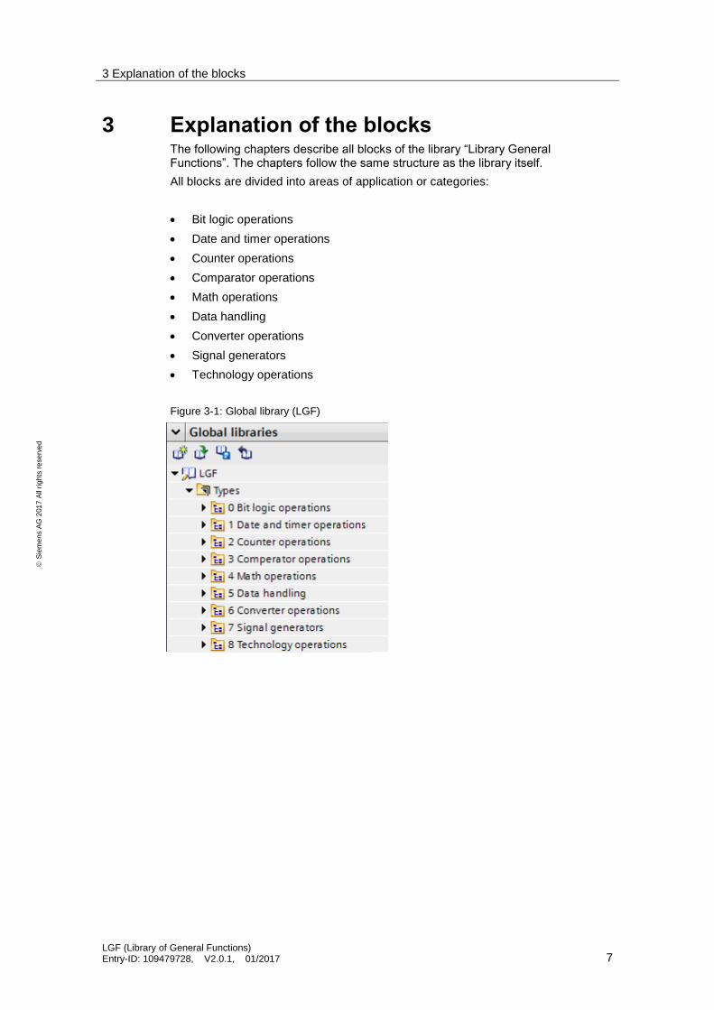
3 Explanation of the blocks The following chapters describe all blocks of the library “Library General Functions”. The chapters follow the same structure as the library itself.
All blocks are divided into areas of application or categories:
Bit logic operations
Date and timer operations
Counter operations
Comparator operations
Math operations
Data handling
Converter operations
Signal generators
Technology operations
Figure 3-1: Global library (LGF)
3 Explanation of the blocks
3.0 Bit logic operations
LGF (Library of General Functions) Entry-ID: 109479728, V2.0.1, 01/2017 8
S
iem
en
s A
G 2
01
7 A
ll ri
gh
ts r
ese
rve
d
3.0 Bit logic operations
3.0.1 FB LGF_PulseRelay
Short description
This block equals a surge relay or a toggle flip-flop including a set and reset input.
Block
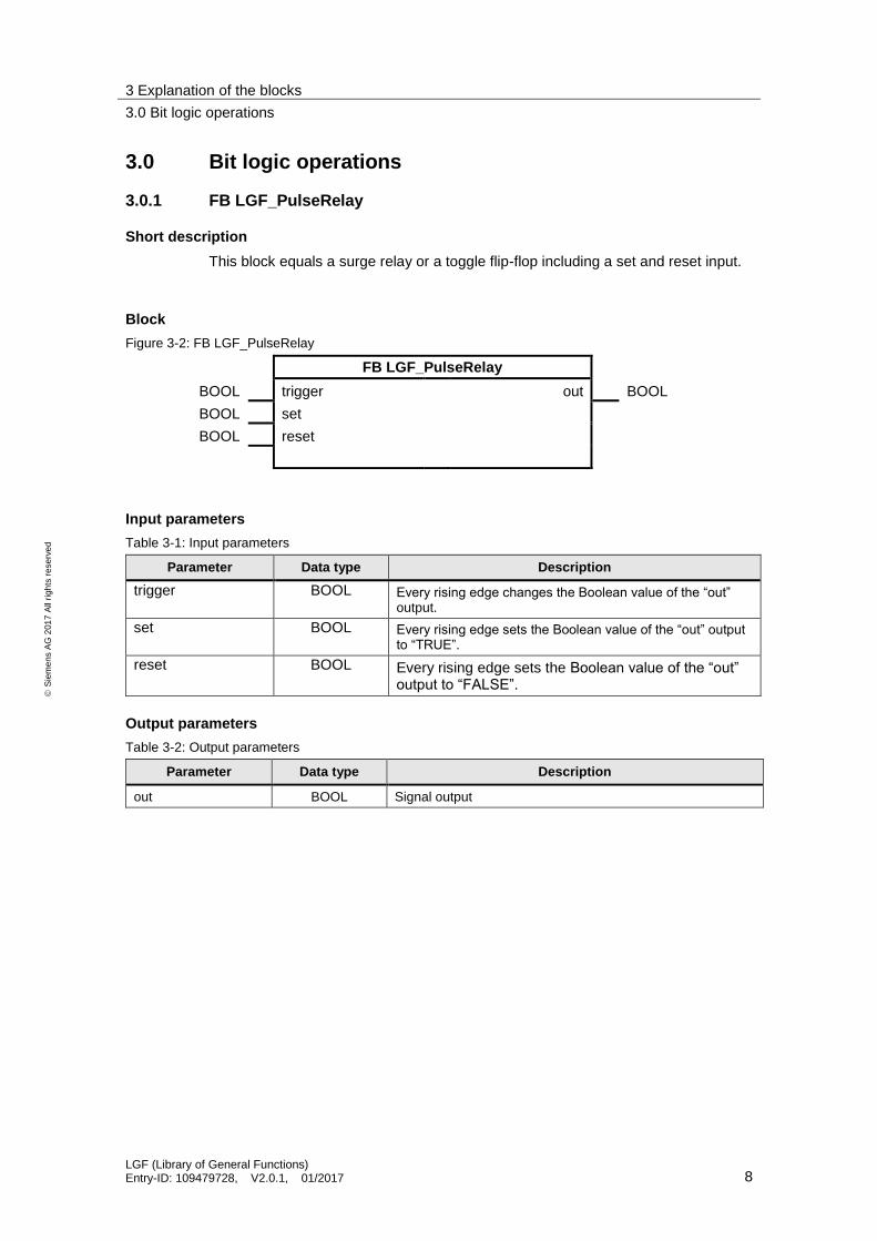
Figure 3-2: FB LGF_PulseRelay
FB LGF_PulseRelay
BOOL trigger out BOOL
BOOL set
BOOL reset
Input parameters
Table 3-1: Input parameters
Parameter Data type Description
trigger BOOL Every rising edge changes the Boolean value of the “out” output.
set BOOL Every rising edge sets the Boolean value of the “out” output to “TRUE”.
reset BOOL Every rising edge sets the Boolean value of the “out” output to “FALSE”.
Output parameters
Table 3-2: Output parameters
Parameter Data type Description
out BOOL Signal output
3 Explanation of the blocks
3.0 Bit logic operations
LGF (Library of General Functions) Entry-ID: 109479728, V2.0.1, 01/2017 9
S
iem
en
s A
G 2
01
7 A
ll ri
gh
ts r
ese
rve
d
Mode of operation
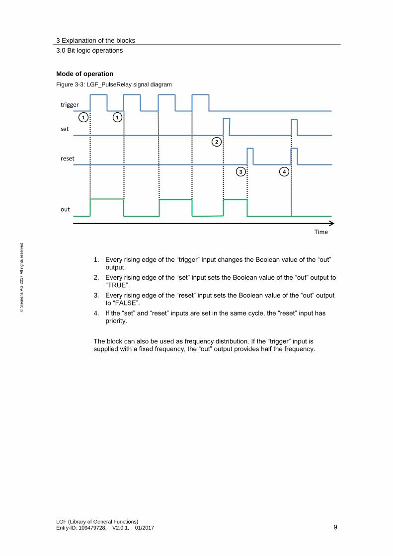
Figure 3-3: LGF_PulseRelay signal diagram
trigger
Time
set
reset
out
1
2
3 4
1
1. Every rising edge of the “trigger” input changes the Boolean value of the “out” output.
2. Every rising edge of the “set” input sets the Boolean value of the “out” output to “TRUE”.
3. Every rising edge of the “reset” input sets the Boolean value of the “out” output to “FALSE”.
4. If the “set” and “reset” inputs are set in the same cycle, the “reset” input has priority.
The block can also be used as frequency distribution. If the “trigger” input is supplied with a fixed frequency, the “out” output provides half the frequency.

3 Explanation of the blocks
3.1 Date and timer operations
LGF (Library of General Functions) Entry-ID: 109479728, V2.0.1, 01/2017 10
S
iem
en
s A
G 2
01
7 A
ll ri
gh
ts r
ese
rve
d
3.1 Date and timer operations
3.1.1 FB LGF_Astro
Short description
This block calculates the sunrise and sunset times for a particular location on earth. The exact position is transmitted to the block in the form of geographic coordinates (longitude and latitude).
Figure 3-4: Earth with longitude and latitude
South Pole
North Pole
West (-) East (+) North (+)
South (-)
60° 120°120° 60°
60°
30°
30°
60°
0°Prime Meridian
Latitude
Longitude
Equator
Information on time synchronization can be found in the following entry: https://support.industry.siemens.com/cs/ww/en/view/86535497
Block
Figure 3-5: FB LGF_Astro
FB LGF_Astro
REAL latitudeDD sunrise DTL
REAL longitudeDD sunset DTL
BOOL modeDMS daytime BOOL
LGF_typeAstroDMS latitudeDMS actSystemTime DTL
LGF_typeAstroDMS longitudeDMS actLocalTime DTL
TIME offsetSunrise error BOOL
TIME offsetSunset statusID UINT
status WORD

3 Explanation of the blocks
3.1 Date and timer operations
LGF (Library of General Functions) Entry-ID: 109479728, V2.0.1, 01/2017 11
S
iem
en
s A
G 2
01
7 A
ll ri
gh
ts r
ese
rve
d
Input parameters
Table 3-3: Input parameters
Parameter Data type Description
latitudeDD REAL Latitude in degrees with decimal values (unit: degrees decimal),
Permissible value range [-90.00000..+90.00000]°
This is a common coordinate format in GPX files (GPS).
longitudeDD REAL Longitude in degrees with decimal values (unit: degrees decimal)
1
Permissible value range [-180.0000..+180.0000]°
modeDMS BOOL 0 : Transfer format of position in “degrees decimal” via the formal parameters “latitudeDD” and “longitudeDD”
1 : Transfer format of position in direction, degree, minute and seconds via the formal parameters “latitudeDMS” and “longitudeDMS”
latitudeDMS LGF_typeAstroDMS Latitude in compass direction; degree; minutes and seconds in the PLC data type “LGF_typeAstroDMS”. Permissible parameter values [N,S]; [0..90]; [0..59]; [0..59] Permissible value range (sum of parameter values) [N, S, n, s]; [0..90]°
This is a common coordinate format in map navigation.
longitudeDMS LGF_typeAstroDMS Longitude in direction; degree; minutes and seconds in the PLC data type “LGF_typeAstroDMS“. Permissible parameter values [E, W]; [0..180]; [0..59]; [0..59] Permissible value range (sum of parameter values) [E, W, e, w]; [0..180]°
The international standard letter designating east is “E” (East).
offsetSunrise TIME Offset of power-on time for “daytime”
offsetSunset TIME Offset of power-off time for “daytime”
Output parameters
Table 3-4: Output parameters
Parameter Data type
Description
sunrise DTL Sunrise at specified location considering the “offsetSunrise“
sunset DTL Sunset at specified location considering the “offsetSunset“
daytime BOOL If the controller’s local time is between “sunrise” and “sunset” then “daytime” returns the value “TRUE”.
actSystemTime DTL Current system time (UTC)
actLocalTime DTL Current local time
error BOOL 0: no errors
1: Block error, “statusID” returns error source, “status” returns error code.
statusID UINT “statusID” returns the ID of the block reporting the status. See table below.
status WORD “status” returns the status/error code (see table below).

3 Explanation of the blocks
3.1 Date and timer operations
LGF (Library of General Functions) Entry-ID: 109479728, V2.0.1, 01/2017 12
S
iem
en
s A
G 2
01
7 A
ll ri
gh
ts r
ese
rve
d
Status and error displays
Table 3-5: Status / error codes
statusID status Meaning Remedy / Notes
1 16#7000 Initial value -
1 16#0000 No faults -
1 16#8200 Incorrect direction information at “latitudeDMS.dir“ input
Only the following characters are allowed: N, n, S, s, W, w, E, e
1 16#8201 Incorrect values at “latitudeDMS” Check the values at
“latitudeDMS.deg“
“latitudeDMS.min“
“latitudeDMS.sec“
1 16#8202 Incorrect direction information at “longitudeDMS.dir”
Only the following characters are allowed: N, n, S, s, W, w, E, e
1 16#8203 Incorrect values at “longitudeDMS” Check the values at
“longitudeDMS.deg”
“longitudeDMS.min”
“longitudeDMS.sec”
1 16#8204 Incorrect value at “latitudeDD” input. Check the actual value at the input.
1 16#8205 Incorrect value at “longitudeDD” input. Check the actual value at the input.
2 - Error/status of subordinate block “RD_SYS_T”.
-
3 - Error/status of subordinate block “RD_LOC_T”.
-
Note If “statusID” is > 1, all values of the “status” output came directly from called up instructions (see table on output parameters). In this case, get the information on the respective instructions from the TIA Portal Online Help.
Mode of operation
If processes are to be run automatically, depending on the day and night change, an astronomical clock function is required. Examples for this would be switching exterior lighting on and off of opening and closing roller shutters.
If these processes are to be executed time-delayed, that is, at a specified time before or after sunrise or sunset, an offset is required for each of them as well.
Note To execute the function exactly, it needs to be ensured that the system time and local time of the SIMATIC controller are set correctly.
Based on the system time/local time of the SIMATIC controller and the set coordinates, the block calculates the sunrise and sunset times. The offset times are added on to the sunrise and sunset and returned at the “sunrise” and “sunset” outputs. If the system time of the SIMATIC controller is in-between these values, the “daytime” output is set to the value “TRUE”.

3 Explanation of the blocks
3.1 Date and timer operations
LGF (Library of General Functions) Entry-ID: 109479728, V2.0.1, 01/2017 13
S
iem
en
s A
G 2
01
7 A
ll ri
gh
ts r
ese
rve
d
Note Because sunrise and sunset times change daily, it is possible that the “daytime” output constantly “remains” on “TRUE” or “FALSE” for a longer period of time:
at correspondingly high offset values
at a location beyond the polar circle
The coordinates can be entered in the “DMS” format (with PLC data type “LGF_typeAstroDMS”), or in “Degree.Decimal”.
Which format is active can be set with the “modeDMS” formal parameter (see Table 3-3).
The entry of the coordinate values is checked for valid values. In case of invalid values, a corresponding error code is returned at “status” (see Table 3-3).
If there is an invalid coordinate value at a formal parameter and if this formal parameter was activated via “modeDMS”, the “sunrise” and “sunset” outputs are set to the value DTL#1970-01-01-00:00:00.
Example
The following example describes the block’s mode of operation.
Table 3-6: Geographic coordinates for Nuremberg-Moorenbrunn, date and system time
longitude: + 11.07675° or E 11° 4' 36''
Latitude: + 49.45203° or N 49° 27' 7''
Date: 8/20/2015 Local time: 09:20 AM
Figure 3-6: FB LGF_Astro, online monitoring of the block with the parameters as well as the actual parameters via the monitoring table

3 Explanation of the blocks
3.1 Date and timer operations
LGF (Library of General Functions) Entry-ID: 109479728, V2.0.1, 01/2017 14
S
iem
en
s A
G 2
01
7 A
ll ri
gh
ts r
ese
rve
d
3.1.2 FB LGF_SetTime
Short description
This block summarizes the functions system time, local time and setting time zone.
Block
Figure 3-7: FB LGF_SetTime
FB LGF_SetTime
BOOL setSystemTimeUTC actSystemTime DTL
DTL systemTimeUTC actLocalTime DTL
BOOL setLocalTime lastSetTimeZone STRING
DTL localTime error BOOL
BOOL setTimeZone statusID UINT
INT timeZone status WORD
BOOL daylightSavingTime
Input parameters
Table 3-7: Input parameters
Parameter Data type Description
setSystemTimeUTC BOOL Rising edge sets the specified system time at the “systemTimeUTC” input
systemTimeUTC DTL Specified system time, corresponds to UTC (Coordinated Universal Time)
setLocalTime BOOL Rising edge sets the specified local time at the “localTime” input
localTime DTL Defined local time
setTimeZone BOOL Rising edge sets
the specified time zone at the “timeZone” input
the specified daylight saving time at the “daylightSavingTime” input
timeZone INT Defined local time (format [+-HHMM]
Examples:
UTC -12:00 [-1200]
UTC -03:30 [-330]
UTC [0]
UTC +13:00 [1300]
daylightSavingTime BOOL TRUE: switch from daylight saving time to standard time (Local time + 60 min)
– from last Sunday in March at 02:00 am
– until last Sunday in October at 3:00 AM
FALSE: no switch from daylight saving time to standard time

3 Explanation of the blocks
3.1 Date and timer operations
LGF (Library of General Functions) Entry-ID: 109479728, V2.0.1, 01/2017 15
S
iem
en
s A
G 2
01
7 A
ll ri
gh
ts r
ese
rve
d
Output parameters
Table 3-8: Output parameters
Parameter Data type Description
systemTime DTL Current system time (UTC)
localTime DTL Current local time
lastSetTimeZone STRING Time zone that has last been set by the block
error BOOL 0: no errors
1: Block error, “statusID” returns error source, “status” returns error code.
statusID UINT “statusID” returns the ID of the block reporting the status. See table below.
status WORD “status” returns the status/error code (see table below).
Status and error displays
Table 3-9: Status / Error codes
statusID status Meaning Remedy / Notes
1 16#7000 Initial value -
1 16#0000 No faults -
1 16#8200 No valid time zone has been returned at the “timeZone” input.
Use only allowed values (see mode of operation).
2 - Error/status of subordinate block “SET_TIMEZONE“
-
Note If “statusID” is > 1, all values of the “status” output came directly from called up instructions (see table on output parameters). In this case, get the information on the respective instructions from the TIA Portal Online Help.
Mode of operation
This block summarizes the functions system time, local time and setting time zone.
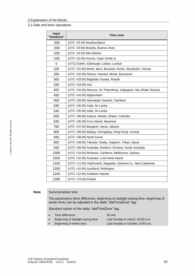
The following time zones are possible at the “timeZone” input.
Input “timeZone”
Time zone
-1200 (UTC -12:00) Eniwetok, Kwajalein
-1100 (UTC -11:00) Midway Island
-1000 (UTC -10:00) Hawaii
-930 (UTC -09:30) (French) Polynesia
-900 (UTC -09:00) Alaska
-800 (UTC -08:00) Tijuana, Los Angeles, Seattle, Vancouver
-700 (UTC -07:00) Arizona, Denver, Salt Lake City, Calgary
-600 (UTC -06:00) Chicago, Dallas, Kansas City, Winnipeg
-500 (UTC -05:00) Eastern Time (USA & Canada)
-400 (UTC -04:00) La Paz, Georgetown
3 Explanation of the blocks
3.1 Date and timer operations
LGF (Library of General Functions) Entry-ID: 109479728, V2.0.1, 01/2017 16
S
iem
en
s A
G 2
01
7 A
ll ri
gh
ts r
ese
rve
d
Input “timeZone”
Time zone
-330 (UTC -03:30) Newfoundland
-300 (UTC -03:00) Brasilia, Buenos Aires
-200 (UTC -02:00) Mid-Atlantic
-100 (UTC -01:00) Azores, Cape Verde Is.
0 (UTC) Dublin, Edinburgh, Lisbon, London
100 (UTC +01:00) Berlin, Bern, Brussels, Rome, Stockholm, Vienna
200 (UTC +02:00) Athens, Istanbul, Minsk, Bucharest
300 (UTC +03:00) Baghdad, Kuwait, Riyadh
330 (UTC +03:00) Iran
400 (UTC +04:00) Moscow, St. Petersburg, Volgograd, Abu Dhabi, Muscat
430 (UTC +04:30) Afghanistan
500 (UTC +05:00) Islamabad, Karachi, Tashkent
530 (UTC +05:30) India, Sri Lanka
545 (UTC +05:45) India, Sri Lanka
600 (UTC +06:00) Astana, Almaty, Dhaka, Colombo
630 (UTC +06:30) Coco Island, Myanmar
700 (UTC +07:00) Bangkok, Hanoi, Jakarta
800 (UTC +08:00) Beijing, Chongqing, Hong Kong, Urumqi
830 (UTC +08:30) North Korea
900 (UTC +09:00) Yakutsk, Osaka, Sapporo, Tokyo, Seoul
930 (UTC +09:30) Australia: Northern Territory, South Australia
1000 (UTC +10:00) Brisbane, Canberra, Melbourne, Sydney
1030 (UTC +10:30) Australia: Lord Howe Island
1100 (UTC +11:00) Vladivostok, Magadan, Solomon Is., New Caledonia
1200 (UTC +12:00) Auckland, Wellington
1245 (UTC +12:45) Chatham Islands
1300 (UTC +13:00) Kiribati
Note Summer/winter time
The parameters (time difference, beginning of daylight saving time, beginning of winter time) can be adjusted in the static “statTimeZone” tag.
Standard values of the static “statTimeZone” tag:
Time difference: 60 min
Beginning of daylight saving time: Last Sunday in march, 02:00 a.m.
Beginning of winter time: Last Sunday in October, 3:00 a.m.

3 Explanation of the blocks
3.1 Date and timer operations
LGF (Library of General Functions) Entry-ID: 109479728, V2.0.1, 01/2017 17
S
iem
en
s A
G 2
01
7 A
ll ri
gh
ts r
ese
rve
d
3.1.3 FB LGF_TimerSwitch
Short description
This block is a timer. It is possible to set daily, weekly, monthly and annual scheduler points, as well as scheduler points for weekdays or weekend days.
Block
Figure 3-8: FB LGF_TimerSwitch
FB LGF_TimerSwitch
USINT onMonth signal BOOL
USINT onDay actLocalTime DTL
USINT onWeekday error BOOL
USINT onWeekOfMonth statusID UINT
USINT onHour status WORD
USINT onMinute
USINT offMonth
USINT offDay
USINT offWeekday
USINT offWeekOfMonth
USINT offHour
USINT offMinute
USINT mode
Input parameters
Table 3-10: Input parameters
Parameter Data type Description
onMonth USINT Month, in which the signal is to be set.
onDay USINT Day, on which the signal is to be set.
onWeekday USINT Weekday, on which the signal is to be set. (Sunday = 1)
onHour USINT Hour, at which the signal is to be set.
onMinute USINT Minute, at which the signal is to be set.
offMonth USINT Month, in which the signal is to be reset.
offDay USINT Day, on which the signal is to be reset.
offWeekday USINT Weekday, on which the signal is to be reset. (Sunday = 1)
offHour USINT Hour, at which the signal is to be reset.
offMinute USINT Minute, at which the signal is to be reset.
mode USINT Specification of module (see operating notes).
3 Explanation of the blocks
3.1 Date and timer operations
LGF (Library of General Functions) Entry-ID: 109479728, V2.0.1, 01/2017 18
S
iem
en
s A
G 2
01
7 A
ll ri
gh
ts r
ese
rve
d
Output parameters
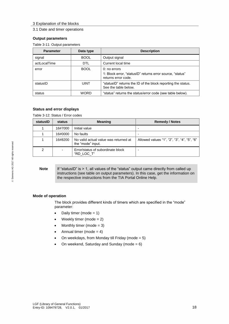
Table 3-11: Output parameters
Parameter Data type Description
signal BOOL Output signal
actLocalTime DTL Current local time
error BOOL 0: no errors
1: Block error, “statusID” returns error source, “status” returns error code.
statusID UINT “statusID” returns the ID of the block reporting the status. See the table below.
status WORD “status” returns the status/error code (see table below).
Status and error displays
Table 3-12: Status / Error codes
statusID status Meaning Remedy / Notes
1 16#7000 Initial value -
1 16#0000 No faults -
1 16#8200 No valid actual value was returned at the “mode” input.
Allowed values “1”, “2”, “3”, “4”, “5”, “6”
2 - Error/status of subordinate block “RD_LOC_T“
-
Note If “statusID” is > 1, all values of the “status” output came directly from called up instructions (see table on output parameters). In this case, get the information on the respective instructions from the TIA Portal Online Help.
Mode of operation
The block provides different kinds of timers which are specified in the “mode” parameter:
Daily timer (mode = 1)
Weekly timer (mode = 2)
Monthly timer (mode = 3)
Annual timer (mode = 4)
On weekdays, from Monday till Friday (mode = 5)
On weekend, Saturday and Sunday (mode = 6)
3 Explanation of the blocks
3.1 Date and timer operations
LGF (Library of General Functions) Entry-ID: 109479728, V2.0.1, 01/2017 19
S
iem
en
s A
G 2
01
7 A
ll ri
gh
ts r
ese
rve
d
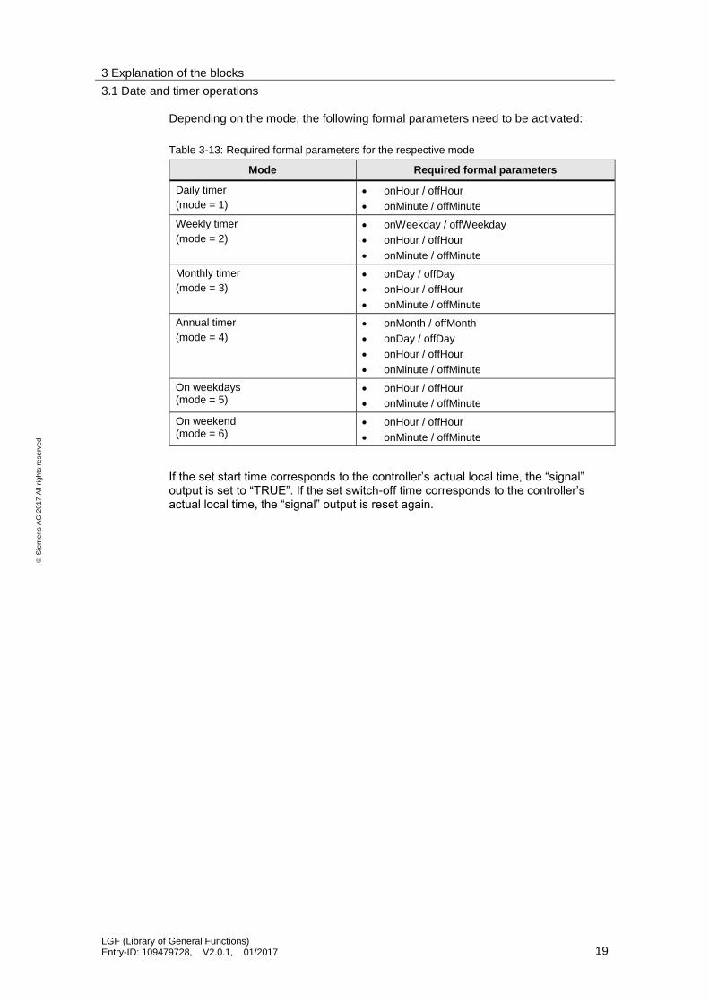
Depending on the mode, the following formal parameters need to be activated:
Table 3-13: Required formal parameters for the respective mode
Mode Required formal parameters
Daily timer
(mode = 1)
onHour / offHour
onMinute / offMinute
Weekly timer
(mode = 2)
onWeekday / offWeekday
onHour / offHour
onMinute / offMinute
Monthly timer
(mode = 3)
onDay / offDay
onHour / offHour
onMinute / offMinute
Annual timer
(mode = 4)
onMonth / offMonth
onDay / offDay
onHour / offHour
onMinute / offMinute
On weekdays (mode = 5)
onHour / offHour
onMinute / offMinute
On weekend (mode = 6)
onHour / offHour
onMinute / offMinute
If the set start time corresponds to the controller’s actual local time, the “signal” output is set to “TRUE”. If the set switch-off time corresponds to the controller’s actual local time, the “signal” output is reset again.
3 Explanation of the blocks
3.2 Counter operations
LGF (Library of General Functions) Entry-ID: 109479728, V2.0.1, 01/2017 20
S
iem
en
s A
G 2
01
7 A
ll ri
gh
ts r
ese
rve
d
3.2 Counter operations
3.2.1 FC LGF_CountFalInDWord
Short description
This block analyses a tag of the DWORD type and returns, how often a 1-0 sequence (falling edge) occurs in the tag.
Application Example
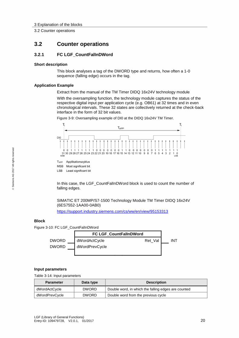
Extract from the manual of the TM Timer DIDQ 16x24V technology module
With the oversampling function, the technology module captures the status of the respective digital input per application cycle (e.g. OB61) at 32 times and in even chronological intervals. These 32 states are collectively returned at the check-back interface in the form of 32 bit values.
Figure 3-9: Oversampling example of DI0 at the DIDQ 16x24V TM Timer.
In this case, the LGF_CountFalInDWord block is used to count the number of falling edges.
SIMATIC ET 200MP/S7-1500 Technology Module TM Timer DIDQ 16x24V (6ES7552-1AA00-0AB0)
https://support.industry.siemens.com/cs/ww/en/view/95153313
Block
Figure 3-10: FC LGF_CountFalInDWord
FC LGF_CountFalInDWord
DWORD dWordActCycle Ret_Val INT
DWORD dWordPrevCycle
Input parameters
Table 3-14: Input parameters
Parameter Data type Description
dWordActCycle DWORD Double word, in which the falling edges are counted
dWordPrevCycle DWORD Double word from the previous cycle

3 Explanation of the blocks
3.2 Counter operations
LGF (Library of General Functions) Entry-ID: 109479728, V2.0.1, 01/2017 21
S
iem
en
s A
G 2
01
7 A
ll ri
gh
ts r
ese
rve
d
Output parameters
Table 3-15: Output parameters
Parameter Data type Description
Ret_Val INT Number of falling edges in the double word
Mode of operation
The block counts the number of falling edges (1-0 transitions) in a tag of the DWORD data type from left to right. In this, the “Ret_Val” output returns the number of falling edges.
For falling edges to be detected at tag limits, the “dWordPrevCycle” input needs to be interconnected with the tag of the previous cycle.
Example
The following example describes the block’s mode of operation. In this case, it is assumed that a signal of unknown length is continually scanned per cycle in the form of double words (DWORD).
Within this signal, 1-0 sequences (falling edges) are to be continually counted and returned. For falling edges to be detected at tag limits as well in this example, the “dWordPrevCycle” input needs to be interconnected with the tag of the previous cycle.
Table 3-16: Example
DWORD previous cycle (dWordPrevCycle)
DWORD actual cycle (dWordActCycle)
1001_0000_0001_1010_1001_0000_0001_1011 0010_1010_0001_1111_0100_0011_1000_0101
Number of 1-0 sequences (falling edges): “Ret_Val“ = 8

3 Explanation of the blocks
3.2 Counter operations
LGF (Library of General Functions) Entry-ID: 109479728, V2.0.1, 01/2017 22
S
iem
en
s A
G 2
01
7 A
ll ri
gh
ts r
ese
rve
d
3.2.2 FC LGF_CountRisInDWord
Short description
This block analyzes a tag of the DWORD type and returns, how often a 0-1 sequence (rising edge) occurs in the tag.
Application example:
Extract from the manual of the TM Timer DIDQ 16x24V technology module:
With the oversampling function, the technology module captures the status of the respective digital input per application cycle (e.g. OB61) at 32 times and in even chronological intervals. These 32 states are collectively returned at the check-back interface in the form of 32 bit values.
Figure 3-11: Oversampling example of DI0 at the DIDQ 16x24V TM Timer.
In this case, the LGF_CountRisInDWord block is used to count the number of rising edges.
SIMATIC ET 200MP/S7-1500 Technology Module TM Timer DIDQ 16x24V (6ES7552-1AA00-0AB0)
https://support.industry.siemens.com/cs/ww/en/view/95153313
Block
Figure 3-12: FC LGF_CountRisInDWord
FC LGF_CountRisInDWord
DWORD dWordActCycle Ret_Val INT
DWORD dWordPrevCycle
Input parameters
Table 3-17: Input parameters
Parameter Data type Description
dWordActCycle DWORD Double word, in which the rising edges are counted
dWordPrevCycle DWORD Double word from the previous cycle

3 Explanation of the blocks
3.2 Counter operations
LGF (Library of General Functions) Entry-ID: 109479728, V2.0.1, 01/2017 23
S
iem
en
s A
G 2
01
7 A
ll ri
gh
ts r
ese
rve
d
Output parameters
Table 3-18: Output parameters
Parameter Data type Description
Ret_Val INT Number of rising edges in the double word
Mode of operation
The block counts the number of rising edges (0-1 transitions) in a tag of the DWORD data type from left to right. In this, the “Ret_Val” output returns the number of rising edges.
For rising edges to be detected at tag limits as well, the “dWordPrevCycle” input needs to be interconnected with the tag of the previous cycle.
Example
The following example describes the block’s mode of operation. In this case, it is assumed that a signal of unknown length is continually scanned per cycle in the form of double words (DWORD).
Within this signal, 0-1 sequences (rising edges) are to be continually counted and returned. For rising edges to be detected at tag limits as well in this example, the “dWordPrevCycle” input needs to be interconnected with the double word of the previous cycle.
Table 3-19: Example
DWORD previous cycle (dWordPrevCycle)
DWORD actual cycle (dWordActCycle)
1001_0000_0001_1010_1001_0000_0001_1010 1010_1010_0001_1111_0100_0011_1000_0101
Number of 0-1 sequences (rising edges): “Ret_Val“ = 9

3 Explanation of the blocks
3.3 Comparator operations
LGF (Library of General Functions) Entry-ID: 109479728, V2.0.1, 01/2017 24
S
iem
en
s A
G 2
01
7 A
ll ri
gh
ts r
ese
rve
d
3.3 Comparator operations
3.3.1 FC LGF_CompareVariant
Short description
This block compares two structured actual parameters (array, PLC data type) and returns, whether they correspond to the same type and have the same values.
Block
Figure 3-13: FC LGF_CompareVariant
FC LGF_CompareVariant
VARIANT variable1 (InOut) Ret_Val BOOL
VARIANT variable2 (InOut) error BOOL
statusID UINT
status WORD
Input/Output parameters (InOut)
Table 3-20: Input/Output parameters (InOut)
Parameter Data type Description
variable1 VARIANT Comparison tag with arbitrary data type
variable2 VARIANT Comparison tag with arbitrary data type
Output parameters
Table 3-21: Output parameters
Parameter Data type Description
Ret_Val BOOL 0: Values of comparison tags or PLC data types differ.
1: Values of comparison tags are the same and PLC data types are identical.
error BOOL 0: no errors
1: Block error, “statusID” returns error source, “status” returns error code.
statusID UINT “statusID” returns the ID of the block reporting the status. See table below.
status WORD “status” returns the status/error code (see table below).

3 Explanation of the blocks
3.3 Comparator operations
LGF (Library of General Functions) Entry-ID: 109479728, V2.0.1, 01/2017 25
S
iem
en
s A
G 2
01
7 A
ll ri
gh
ts r
ese
rve
d
Status and error displays
Table 3-22: Status / Error codes
statusID status Meaning Remedy / Notes
1 16#7000 Initial value -
1 16#0000 No faults -
Mode of operation
This block compares two (structured) actual parameters and returns, whether they correspond to the same value.
Note The following differences cannot be detected with the comparison method (byte level):
Tags of the “Struct” data type cannot be compared.
With strings, differences may occur in the range between actual length and maximum length.
A disparity can also be displayed with “same” tags, if the structure contains REAL numbers.
Tags of the “ARRAY of BOOL“ type cannot be checked for equality with the function, because the used “CountOfElements” instruction also counts the filling elements (e.g. with an ARRAY[0..1] of BOOL, 8 is returned).

3 Explanation of the blocks
3.4 Math operations
LGF (Library of General Functions) Entry-ID: 109479728, V2.0.1, 01/2017 26
S
iem
en
s A
G 2
01
7 A
ll ri
gh
ts r
ese
rve
d
3.4 Math operations
3.4.1 FC LGF_AverageAndDeviation
Short description
This block determines the arithmetic average and the standard deviation from a series of numbers.
Block
Figure 3-14: FC LGF_AverageAndDeviation
FC LGF_AverageAndDeviation
VARIANT variableArray arithmeticAverage REAL
standardDeviation REAL
error BOOL
statusID UINT
status WORD
Input parameters
Table 3-23: Input parameters
Parameter Data type Description
variableArray VARIANT Series of numbers, which are used for calculation
Output parameters
Table 3-24: Output parameters
Parameter Data type Description
arithmeticAverage REAL Arithmetic mean
standardDeviation REAL Standard deviation
error BOOL 0: no errors
1: Block error, “statusID” returns error source, “status” returns error code.
statusID UINT “statusID” returns the ID of the block reporting the status. See the table below.
status WORD “status” returns the status/error code (see table below).
3 Explanation of the blocks
3.4 Math operations
LGF (Library of General Functions) Entry-ID: 109479728, V2.0.1, 01/2017 27
S
iem
en
s A
G 2
01
7 A
ll ri
gh
ts r
ese
rve
d
Status and error displays
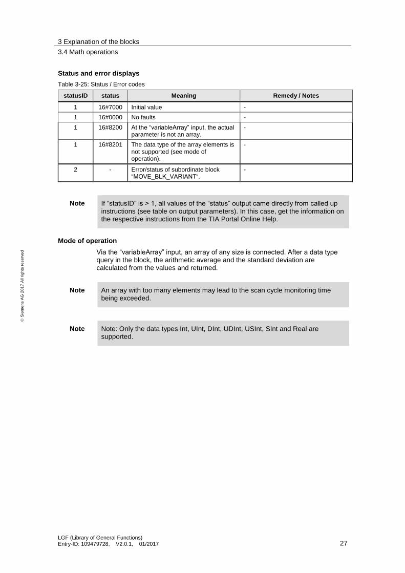
Table 3-25: Status / Error codes
statusID status Meaning Remedy / Notes
1 16#7000 Initial value -
1 16#0000 No faults -
1 16#8200 At the “variableArray” input, the actual parameter is not an array.
-
1 16#8201 The data type of the array elements is not supported (see mode of operation).
-
2 - Error/status of subordinate block “MOVE_BLK_VARIANT“.
-
Note If “statusID” is > 1, all values of the “status” output came directly from called up instructions (see table on output parameters). In this case, get the information on the respective instructions from the TIA Portal Online Help.
Mode of operation
Via the “variableArray” input, an array of any size is connected. After a data type query in the block, the arithmetic average and the standard deviation are calculated from the values and returned.
Note An array with too many elements may lead to the scan cycle monitoring time being exceeded.
Note Note: Only the data types Int, UInt, DInt, UDInt, USInt, SInt and Real are supported.

3 Explanation of the blocks
3.4 Math operations
LGF (Library of General Functions) Entry-ID: 109479728, V2.0.1, 01/2017 28
S
iem
en
s A
G 2
01
7 A
ll ri
gh
ts r
ese
rve
d
3.4.2 FB LGF_FloatingAverage
Short description
This block calculates a moving arithmetic average from REAL values. This method can be used to smooth a data series. The values can be read in cyclically or triggered.
Block
Figure 3-15: LGF_FloatingAverage
FB LGF_FloatingAverage
REAL value average REAL
INT mode error BOOL
BOOL trigger status WORD
BOOL reset
Input parameters
Table 3-26: Input parameters
Parameter Data type Description
value REAL Values from which the moving average is to be determined.
mode INT Selection of mode (see mode of operation); Default: mode=1.
trigger BOOL Trigger tag, impulse
reset BOOL The block is reset and the calculation starts over.
Note The “LGF_FloatingAverage” block does not perform a data type query for the “value” input parameter. With data types other than REAL, either an implicit conversion is performed automatically, or an error is generated during translation.
Further information can be found in the chapter “Overview of data type conversion” in the TIA Portal online help or under:
https://support.industry.siemens.com/cs/ww/en/view/109011420/58427923211
Output parameters
Table 3-27: Output parameters
Parameter Data type Description
average REAL Moving average
error BOOL 0: no errors
1: Block errors
status WORD Status/ error code (see table below)

3 Explanation of the blocks
3.4 Math operations
LGF (Library of General Functions) Entry-ID: 109479728, V2.0.1, 01/2017 29
S
iem
en
s A
G 2
01
7 A
ll ri
gh
ts r
ese
rve
d
Status and error displays
Table 3-28: Status / Error codes
statusID status Meaning Remedy / Notes
1 16#0000 No faults -
1 16#8201 No mode selected Select a mode (1 or 2).
Mode of operation
The block calculates the (moving) average of the last 100 values that have been read in. After reading in 100 values, the current value that has been read in always replaces the oldest value (FIFO principle).
To read in the values, two modes are available which are determined via the “mode” parameter:
mode = 1: Read in with each impulse at the “trigger” input
mode = 2: Cyclic read in
The block is activated as soon as a mode has been selected. It is possible to select between the modes during operation.
Note In this block, a range of 100 values has been determined for the moving average calculation. You can adapt the range to your requirements by adjusting the default value of “WINDOW_SIZE” in the block’s block interface under “Constant”.
3 Explanation of the blocks
3.4 Math operations
LGF (Library of General Functions) Entry-ID: 109479728, V2.0.1, 01/2017 30
S
iem
en
s A
G 2
01
7 A
ll ri
gh
ts r
ese
rve
d
3.4.3 FC LGF_MatrixAddition
Short description
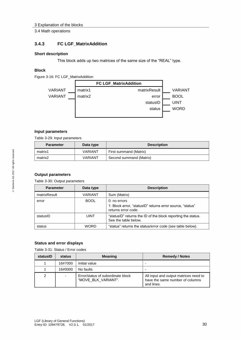
This block adds up two matrices of the same size of the “REAL” type.
Block
Figure 3-16: FC LGF_MatrixAddition
FC LGF_MatrixAddition
VARIANT matrix1 matrixResult VARIANT
VARIANT matrix2 error BOOL
statusID UINT
status WORD
Input parameters
Table 3-29: Input parameters
Parameter Data type Description
matrix1 VARIANT First summand (Matrix)
matrix2 VARIANT Second summand (Matrix)
Output parameters
Table 3-30: Output parameters
Parameter Data type Description
matrixResult VARIANT Sum (Matrix)
error BOOL 0: no errors
1: Block error, “statusID” returns error source, “status” returns error code.
statusID UINT “statusID” returns the ID of the block reporting the status. See the table below.
status WORD “status” returns the status/error code (see table below).
Status and error displays
Table 3-31: Status / Error codes
statusID status Meaning Remedy / Notes
1 16#7000 Initial value -
1 16#0000 No faults -
2 - Error/status of subordinate block “MOVE_BLK_VARIANT“.
All input and output matrices need to have the same number of columns and lines.

3 Explanation of the blocks
3.4 Math operations
LGF (Library of General Functions) Entry-ID: 109479728, V2.0.1, 01/2017 31
S
iem
en
s A
G 2
01
7 A
ll ri
gh
ts r
ese
rve
d
Note If “statusID” is > 1, all values of the “status” output came directly from called up instructions (see table on output parameters). In this case, get the information on the respective instructions from the TIA Portal Online Help.
Mode of operation
The block adds up two matrices of the same size. The individual fields of the two incoming matrices are read, added up and then returned in the “matrixResults” matrix.
Note Please note that all input and output matrices need to have the same number of columns and lines.
3 Explanation of the blocks
3.4 Math operations
LGF (Library of General Functions) Entry-ID: 109479728, V2.0.1, 01/2017 32
S
iem
en
s A
G 2
01
7 A
ll ri
gh
ts r
ese
rve
d
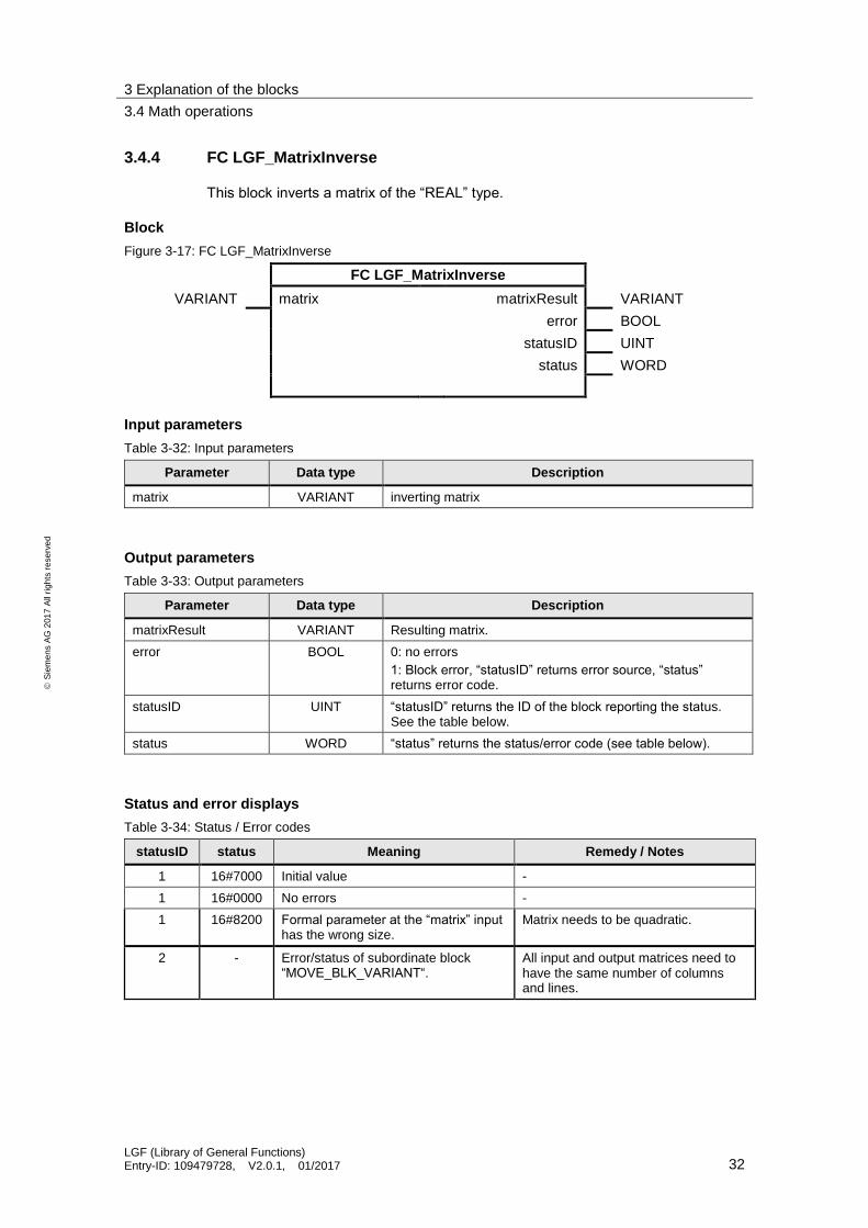
3.4.4 FC LGF_MatrixInverse
This block inverts a matrix of the “REAL” type.
Block
Figure 3-17: FC LGF_MatrixInverse
FC LGF_MatrixInverse
VARIANT matrix matrixResult VARIANT
error BOOL
statusID UINT
status WORD
Input parameters
Table 3-32: Input parameters
Parameter Data type Description
matrix VARIANT inverting matrix
Output parameters
Table 3-33: Output parameters
Parameter Data type Description
matrixResult VARIANT Resulting matrix.
error BOOL 0: no errors
1: Block error, “statusID” returns error source, “status” returns error code.
statusID UINT “statusID” returns the ID of the block reporting the status. See the table below.
status WORD “status” returns the status/error code (see table below).
Status and error displays
Table 3-34: Status / Error codes
statusID status Meaning Remedy / Notes
1 16#7000 Initial value -
1 16#0000 No errors -
1 16#8200 Formal parameter at the “matrix” input has the wrong size.
Matrix needs to be quadratic.
2 - Error/status of subordinate block “MOVE_BLK_VARIANT“.
All input and output matrices need to have the same number of columns and lines.

3 Explanation of the blocks
3.4 Math operations
LGF (Library of General Functions) Entry-ID: 109479728, V2.0.1, 01/2017 33
S
iem
en
s A
G 2
01
7 A
ll ri
gh
ts r
ese
rve
d
Note If “statusID” is > 1, all values of the “status” output came directly from called up instructions (see table on output parameters). In this case, get the information on the respective instructions from the TIA Portal Online Help.
Mode of operation
The block inverts a matrix of any size with the Shipley-Coleman procedure.
Note Note that the matrix needs to be quadratic. This means that the number of lines needs to be equal to the number of columns.
The output matrix needs to be dimensioned as large as the input matrix.

3 Explanation of the blocks
3.4 Math operations
LGF (Library of General Functions) Entry-ID: 109479728, V2.0.1, 01/2017 34
S
iem
en
s A
G 2
01
7 A
ll ri
gh
ts r
ese
rve
d
3.4.5 FC LGF_MatrixMultiplication
Short description
This block adds up two matrices of the “REAL” type.
Block
Figure 3-18: FC LGF_MatrixMultiplication
FC LGF_MatrixMultiplication
VARIANT matrix1 matrixResult VARIANT
INT rows1 error BOOL
INT columns1 statusID UINT
VARIANT matrix2 status WORD
INT rows2
INT columns2
Input parameters
Table 3-35: Input parameters
Parameter Data type Description
matrix1 VARIANT First factor: Matrix to be multiplied
rows1 INT Number of rows of the first matrix.
columns1 INT Number of columns of the first matrix.
matrix2 VARIANT Second factor: Matrix to be multiplied
rows1 INT Number of rows of the second matrix.
columns1 INT Number of columns of the second matrix.
Output parameters
Table 3-36: Output parameters
Parameter Data type Description
matrixResult VARIANT Product: The resulting matrix
error BOOL 0: no errors
1: Block error, “statusID” returns error source, “status” returns error code.
statusID UINT “statusID” returns the ID of the block reporting the status. See table below.
status WORD “status” returns the status/error code (see table below).

3 Explanation of the blocks
3.4 Math operations
LGF (Library of General Functions) Entry-ID: 109479728, V2.0.1, 01/2017 35
S
iem
en
s A
G 2
01
7 A
ll ri
gh
ts r
ese
rve
d
Status and error displays
Table 3-37: Status / Error codes
statusID status Meaning Remedy / Notes
1 16#7000 Initial value -
1 16#0000 No errors -
1 16#8200 The number of columns of the first matrix does not correspond to the number of rows of the second matrix.
-
2 - Error/status of subordinate block “MOVE_BLK_VARIANT“.
Check the matrices and the respective rows and columns.
Note If “statusID” is > 1, all values of the “status” output came directly from called up instructions (see table on output parameters). In this case, get the information on the respective instructions from the TIA Portal Online Help.
Mode of operation
The block adds up two matrices of varying sizes. The individual elements of the two incoming matrices are read, added up and then returned in the “matrixResults” matrix.
Note Note that the numbers of rows of the first matrix needs to be equal to the number of columns of the second matrix.
The size of the output matrix (m * n) results from the number of rows (m) of “matrix1” and the number of columns (n) from “matrix2”.

3 Explanation of the blocks
3.4 Math operations
LGF (Library of General Functions) Entry-ID: 109479728, V2.0.1, 01/2017 36
S
iem
en
s A
G 2
01
7 A
ll ri
gh
ts r
ese
rve
d
3.4.6 FC LGF_MatrixSubtraction
This block subtracts a matrix of the “REAL” type from another.
Block
Figure 3-19: FC LGF_MatrixSubtraction
FC LGF_MatrixSubtraction
VARIANT matrix1 matrixResult VARIANT
VARIANT matrix2 error BOOL
statusID UINT
status WORD
Input parameters
Table 3-38: Input parameters
Parameter Data type Description
matrix1 VARIANT Minuend: From this matrix, “matrix2” is subtracted.
matrix2 VARIANT Subtrahend: This matrix is subtracted from “matrix1”.
Output parameters
Table 3-39: Output parameters
Parameter Data type Description
matrixResult VARIANT Difference: The resulting matrix
error BOOL 0: no errors
1: Block error, “statusID” returns error source, “status” returns error code.
statusID UINT “statusID” returns the ID of the block reporting the status. See table below.
status WORD “status” returns the status/error code (see table below).
Status and error displays
Table 3-40: Status / Error codes
statusID status Meaning Remedy / Notes
1 16#7000 Initial value -
1 16#0000 No errors -
2 - Error/status of subordinate block “MOVE_BLK_VARIANT“.
All input and output matrices need to have the same number of columns and rows.

3 Explanation of the blocks
3.4 Math operations
LGF (Library of General Functions) Entry-ID: 109479728, V2.0.1, 01/2017 37
S
iem
en
s A
G 2
01
7 A
ll ri
gh
ts r
ese
rve
d
Note If “statusID” is > 1, all values of the “status” output came directly from called up instructions (see table on output parameters). In this case, get the information on the respective instructions from the TIA Portal Online Help.
Mode of operation
The block subtracts two matrices of varying sizes. The individual fields of the two matrices are read, subtracted and then returned in the “matrixResults” matrix.
Note Please note that all input and output matrices need to have the same number of columns and rows.

3 Explanation of the blocks
3.4 Math operations
LGF (Library of General Functions) Entry-ID: 109479728, V2.0.1, 01/2017 38
S
iem
en
s A
G 2
01
7 A
ll ri
gh
ts r
ese
rve
d
3.4.7 FC LGF_MatrixTranspose
This block transports a matrix.
Block
Figure 3-20: FC LGF_MatrixTranspose
FC LGF_MatrixTranspose
VARIANT matrix matrixResult VARIANT
INT rows error BOOL
INT columns statusID UINT
status WORD
Input parameters
Table 3-41: Input parameters
Parameter Data type Description
matrix VARIANT Matrix to be transposed.
rows INT Number of rows of the matrix to be transposed.
columns INT Number of columns of the matrix to be transposed.
Output parameters
Table 3-42: Output parameters
Parameter Data type Description
matrixResult VARIANT The resulting matrix.
error BOOL 0: no errors
1: Block error, “statusID” returns error source, “status” returns error code.
statusID UINT “statusID” returns the ID of the block reporting the status. See table below.
status WORD “status” returns the status/error code (see table below).
Status and error displays
Table 3-43: Status / Error codes
statusID status Meaning Remedy / Notes
1 16#7000 Initial value -
1 16#0000 No errors -
2 - Error/status of subordinate block “MOVE_BLK_VARIANT“.
All input and output matrices need to have the same number of columns and rows.

3 Explanation of the blocks
3.4 Math operations
LGF (Library of General Functions) Entry-ID: 109479728, V2.0.1, 01/2017 39
S
iem
en
s A
G 2
01
7 A
ll ri
gh
ts r
ese
rve
d
Note If “statusID” is > 1, all values of the “status” output came directly from called up instructions (see table on output parameters). In this case, get the information on the respective instructions from the TIA Portal Online Help.
Mode of operation
The block transposes a matrix of any size. During this, the rows and the columns are reversed (mirrored).
Note Note that the numbers of columns of the output matrix needs to be equal to the number of rows of the input matrix. The numbers of rows of the output matrix needs to be equal to the number of columns of the input matrix.
3 Explanation of the blocks
3.4 Math operations
LGF (Library of General Functions) Entry-ID: 109479728, V2.0.1, 01/2017 40
S
iem
en
s A
G 2
01
7 A
ll ri
gh
ts r
ese
rve
d
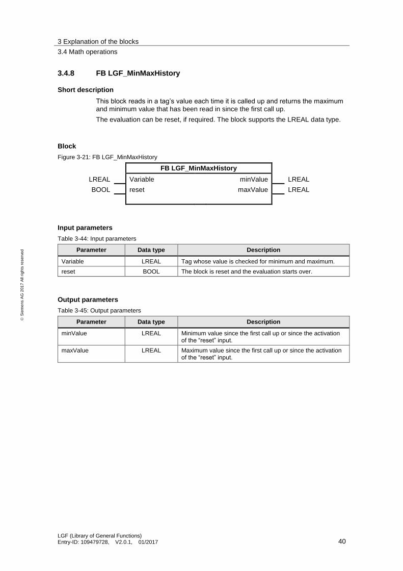
3.4.8 FB LGF_MinMaxHistory
Short description
This block reads in a tag’s value each time it is called up and returns the maximum and minimum value that has been read in since the first call up.
The evaluation can be reset, if required. The block supports the LREAL data type.
Block
Figure 3-21: FB LGF_MinMaxHistory
FB LGF_MinMaxHistory
LREAL Variable minValue LREAL
BOOL reset maxValue LREAL
Input parameters
Table 3-44: Input parameters
Parameter Data type Description
Variable LREAL Tag whose value is checked for minimum and maximum.
reset BOOL The block is reset and the evaluation starts over.
Output parameters
Table 3-45: Output parameters
Parameter Data type Description
minValue LREAL Minimum value since the first call up or since the activation of the “reset” input.
maxValue LREAL Maximum value since the first call up or since the activation of the “reset” input.

3 Explanation of the blocks
3.4 Math operations
LGF (Library of General Functions) Entry-ID: 109479728, V2.0.1, 01/2017 41
S
iem
en
s A
G 2
01
7 A
ll ri
gh
ts r
ese
rve
d
3.4.9 FC LGF_RandomINT / LGF_RandomReal
Short description
This block generates a “random” value between a defined maximum and minimum value per call up. The random number has the INT /REAL data type.
Block
Figure 3-22: FC LGF_RandomINT / FC LGF_RandomReal
FC LGF_Random…
INT / REAL maxValue Ret_Val INT / REAL
INT / REAL minValue error BOOL
statusID UINT
status WORD
Input parameters
Table 3-46: Input parameters
Parameter Data type Description
maxValue INT / REAL Defines the random number’s upper limit value.
minValue INT / REAL Defines the random number’s lower limit value.
Output parameters
Table 3-47: Output parameters
Parameter Data type Description
Ret_Val INT / REAL Random number
error BOOL 0: no errors
1: Block error, “statusID” returns error source, “status” returns error code.
statusID UINT “statusID” returns the ID of the block reporting the status. See table below.
status WORD “status” returns the status/error code (see table below).
Status and error displays
Table 3-48: Status / Error codes
statusID status Meaning Remedy / Notes
1 16#7000 Initial value -
1 16#0000 No errors -
1 16#8200 “minValue“ is greater than “maxValue“.
-
2 - Error/status of subordinate block “RD_SYS_T“.
-

3 Explanation of the blocks
3.4 Math operations
LGF (Library of General Functions) Entry-ID: 109479728, V2.0.1, 01/2017 42
S
iem
en
s A
G 2
01
7 A
ll ri
gh
ts r
ese
rve
d
Note If “statusID” is > 1, all values of the “status” output came directly from called up instructions (see table on output parameters). In this case, get the information on the respective instructions from the TIA Portal Online Help.
Mode of operation
This block generates random values that are between the specified “minValue” value and “maxValue” value. This random value is returned via “Ret-Val”.
Background information
For the random value to be as random as possible, two important program steps are performed. Every time the block is called up, a new star value is used. As start value, the nanoseconds of the current daytime are used. In order to ensure that the output value is not constantly increasing, the ten thousands, thousands, hundreds, tens and units are transposed and partly exchanged. This process depends on the current second of the controller’s system time.
Note If no maximum and minimum value (= 0) is determined, the block returns random values from the entire range of values of INT / REAL.

3 Explanation of the blocks
3.4 Math operations
LGF (Library of General Functions) Entry-ID: 109479728, V2.0.1, 01/2017 43
S
iem
en
s A
G 2
01
7 A
ll ri
gh
ts r
ese
rve
d
3.4.10 FC LGF_SearchMinMax
Short description
This block searches for the maximum and minimum value as well as the respective index in an array.
The following data types of the array elements are supported: Int, DInt, UInt, UDInt, USInt, SInt and Real.
Block
Figure 3-23: FC LGF_SearchMinMax
FC LGF_SearchMinMax
VARIANT variableArray min VARIANT
minArrayIndex INT
max VARIANT
maxArrayIndex INT
error BOOL
statusID UINT
status WORD
Input parameters
Table 3-49: Input parameters
Parameter Data type Description
variableArray VARIANT Array in whose fields the maximum and minimum is searched for.
Output parameters
Table 3-50: Output parameters
Parameter Data type Description
minValue VARIANT Smallest value found.
minArrayIndex INT Start index of the array plus minArrayIndex results in the array index of the smallest value. The index starts with 0.
maxValue VARIANT Largest value found.
maxArrayIndex INT Start index of the array plus maxArrayIndex results in the array index of the largest value. The index starts with 0.
error BOOL 0: no errors
1: Block error, “statusID” returns error source, “status” returns error code.
statusID UINT “statusID” returns the ID of the block reporting the status. See table below.
status WORD “status” returns the status/error code (see table below).

3 Explanation of the blocks
3.4 Math operations
LGF (Library of General Functions) Entry-ID: 109479728, V2.0.1, 01/2017 44
S
iem
en
s A
G 2
01
7 A
ll ri
gh
ts r
ese
rve
d
Status and error displays
Table 3-51: Status / Error codes
statusID status Meaning Remedy / Notes
1 16#7000 Initial value -
1 16#0000 No errors -
1 16#8200 At the “variableArray” input, the actual parameter is not an array.
-
1 16#8201 The data type of the elements of the array is not supported.
Only the data types Int, UInt, DInt, UDInt, USInt, SInt and Real are supported.
1 16#8202 The elements of the array do not have the same data type as the “minValue” and “maxValue” outputs.
-
2 - Error/status of subordinate block “MOVE_BLK_VARIANT“.
-
Note If “statusID” is > 1, all values of the “status” output came directly from called up instructions (see table on output parameters). In this case, get the information on the respective instructions from the TIA Portal Online Help.
Mode of operation
Via the “variableArray” input, an array of any size is connected. After a data type query in the block, the elements are one after another copied into a tag of the respective type and compared. The smallest and the largest value are returned as well as their respective index in the array.
Note With multiple identical minimum and maximum values, the index of the first minimum or maximum value is returned.

3 Explanation of the blocks
3.4 Math operations
LGF (Library of General Functions) Entry-ID: 109479728, V2.0.1, 01/2017 45
S
iem
en
s A
G 2
01
7 A
ll ri
gh
ts r
ese
rve
d
3.4.11 FC LGF_XRoot
Short description
This block calculates the xth root of a numerical tag.
Block
Figure 3-24: FC LGF_Random
FC LGF_XRoot
REAL Variable Ret_Val REAL
REAL root
Input parameters
Table 3-52: Input parameters
Parameter Data type Description
Variable REAL Tag, of which the root is to be calculated.
root REAL Root (e.g. 3 as third root)
Output parameters
Table 3-53: Output parameters
Parameter Data type Description
Ret_Val REAL Output of result
Mode of operation
The block calculates the nth root of a number. To perform this function, the following formula is extended.
𝑛𝑢𝑚𝑏𝑒𝑟 = 𝑒𝑙𝑜𝑔𝑒(𝑛𝑢𝑚𝑏𝑒𝑟)
This results in:
𝑅𝑒𝑡_𝑉𝑎𝑙 = √𝑛𝑢𝑚𝑏𝑒𝑟𝑟𝑜𝑜𝑡
= 𝑛𝑢𝑚𝑏𝑒𝑟1
𝑟𝑜𝑜𝑡 = (𝑒𝑙𝑜𝑔𝑒(𝑛𝑢𝑚𝑏𝑒𝑟))1
𝑟𝑜𝑜𝑡 = 𝑒ln(𝑛𝑢𝑚𝑏𝑒𝑟)∗
1𝑟𝑜𝑜𝑡
In STEP 7 (TIA Portal) the function equals “EXP“ e(…)
and the function “LN“ ln(…).
This results in the following formula:
𝑅𝑒𝑡_𝑉𝑎𝑙 = 𝐸𝑋𝑃((1 𝑟𝑜𝑜𝑡⁄ ) ∗ LN(𝑛𝑢𝑚𝑏𝑒𝑟))

3 Explanation of the blocks
3.5 Data handling
LGF (Library of General Functions) Entry-ID: 109479728, V2.0.1, 01/2017 46
S
iem
en
s A
G 2
01
7 A
ll ri
gh
ts r
ese
rve
d
3.5 Data handling
3.5.1 FB LGF_FIFO
Short description
This block stores incoming jobs/data and returns the oldest job that has not yet been processed.
Block
Figure 3-25: FB LGF_FIFO
FB LGF_FIFO
BOOL execute done BOOL
BOOL mode error BOOL
VARIANT initialValue statusID UINT
BOOL resetBuffer status WORD
VARIANT item (InOut)
VARIANT buffer (InOut)
Input parameters
Table 3-54: Input parameters
Parameter Data type Description
execute BOOL Requirement of a pass.
mode BOOL Selecting the mode.
TRUE: Writing of “item” value into “buffer”
FALSE: Reading the value from “buffer” and output at “item”
initialValue VARIANT Value for initialization of ring buffer (usually: 0 )
resetBuffer BOOL Clearing out and initializing the ring buffer.
Input/Output parameters (InOut)
Table 3-55: Input/Output parameters (InOut)
Parameter Data type Description
item VARIANT Value that is returned from the ring buffer or is to be written into the ring buffer.
buffer VARIANT Ring buffer (Array of … )
3 Explanation of the blocks
3.5 Data handling
LGF (Library of General Functions) Entry-ID: 109479728, V2.0.1, 01/2017 47
S
iem
en
s A
G 2
01
7 A
ll ri
gh
ts r
ese
rve
d
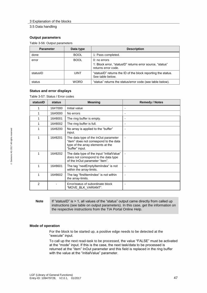
Output parameters
Table 3-56: Output parameters
Parameter Data type Description
done BOOL 1: Pass completed.
error BOOL 0: no errors
1: Block error, “statusID” returns error source, “status” returns error code.
statusID UINT “statusID” returns the ID of the block reporting the status. See table below.
status WORD “status” returns the status/error code (see table below).
Status and error displays
Table 3-57: Status / Error codes
statusID status Meaning Remedy / Notes
1 16#7000 Initial value -
1 16#0000 No errors -
1 16#8001 The ring buffer is empty. -
1 16#8002 The ring buffer is full. -
1 16#8200 No array is applied to the “buffer” input.
-
1 16#8201 The data type of the InOut parameter “item” does not correspond to the data type of the array elements at the “buffer” input.
-
1 16#8202 The data type of the input “initialValue” does not correspond to the data type of the InOut parameter “item”.
-
1 16#8601 The tag “nextEmptyItemIndex“ is not within the array-limits.
-
1 16#8602 The tag “firstItemIndex“ is not within the array-limits.
-
2 - Error/status of subordinate block “MOVE_BLK_VARIANT“.
-
Note If “statusID” is > 1, all values of the “status” output came directly from called up instructions (see table on output parameters). In this case, get the information on the respective instructions from the TIA Portal Online Help.
Mode of operation
For the block to be started up, a positive edge needs to be detected at the “execute” input.
To call up the next read-task to be processed, the value “FALSE” must be activated at the “mode” input. If this is the case, the next task/data to be processed is returned at the “item” InOut parameter and this field is replaced in the ring buffer with the value at the “initialValue” parameter.
3 Explanation of the blocks
3.5 Data handling
LGF (Library of General Functions) Entry-ID: 109479728, V2.0.1, 01/2017 48
S
iem
en
s A
G 2
01
7 A
ll ri
gh
ts r
ese
rve
d
To save a new write task in the ring buffer, the “TRUE” value needs to be activated at the “mode” input. If this is the case, the value at the “item” InOut parameter or the task in the ring buffer is saved at the next free location.
If during a pass, the “TRUE” value is activated at the “resetBuffer” input, all fields in the ring buffer are reset to the value specified at the “InitialValue” input. After this, the ring buffer can once more be filled with tasks/data.

3 Explanation of the blocks
3.5 Data handling
LGF (Library of General Functions) Entry-ID: 109479728, V2.0.1, 01/2017 49
S
iem
en
s A
G 2
01
7 A
ll ri
gh
ts r
ese
rve
d
3.5.2 FB LGF_ShellSortInt / LGF_ShellSortUInt / LGF_ShellSortReal
Short description
This block sorts an array with any number of elements (1000 max.) in ascending or descending order. The following data types are supported:
Array of “Int“ type: LGF_ShellSortInt
Array of “UInt“ type: LGF_ShellSortUInt
Array of “Real“ type: LGF_ShellSortReal
Block
Figure 3-26: FB LGF_ShellSort…
FB LGF_ShellSort…
BOOL mode done BOOL
error BOOL
VARIANT variantArray (InOut) statusID UINT
status WORD
Input parameters
Table 3-58: Input parameters
Parameter Data type Description
mode BOOL 0: sort in ascending order (default)
1: sort in descending order
Input/Output parameters (InOut)
Table 3-59: Input/Output parameters (InOut)
Parameter Data type Description
variantArray VARIANT Array that is to be sorted.
Output parameters
Table 3-60: Output parameters
Parameter Data type Description
done BOOL 1: Sorting completed.
error BOOL 0: no errors
1: Block error, “statusID” returns error source, “status” returns error code.
statusID UINT “statusID” returns the ID of the block reporting the status. See table below.
status WORD “status” returns the status/error code (see table below).
3 Explanation of the blocks
3.5 Data handling
LGF (Library of General Functions) Entry-ID: 109479728, V2.0.1, 01/2017 50
S
iem
en
s A
G 2
01
7 A
ll ri
gh
ts r
ese
rve
d
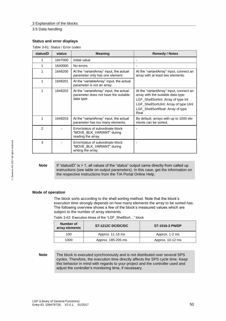
Status and error displays
Table 3-61: Status / Error codes
statusID status Meaning Remedy / Notes
1 16#7000 Initial value -
1 16#0000 No errors -
1 16#8200 At the “variantArray” input, the actual parameter only has one element.
At the “variantArray” input, connect an array with at least two elements.
1 16#8201 At the “variableArray” input, the actual parameter is not an array.
1 16#8202 At the “variantArray” input, the actual parameter does not have the suitable data type.
At the “variantArray” input, connect an array with the suitable data type:
LGF_ShellSortInt: Array of type Int
LGF_ShellSortUInt: Array of type UInt
LGF_ShellSortReal: Array of type Real
1 16#8203 At the “variantArray” input, the actual parameter has too many elements.
By default, arrays with up to 1000 ele-ments can be sorted.
2 - Error/status of subordinate block “MOVE_BLK_VARIANT“ during reading the array.
-
3 - Error/status of subordinate block “MOVE_BLK_VARIANT“ during writing the array.
-
Note If “statusID” is > 1, all values of the “status” output came directly from called up instructions (see table on output parameters). In this case, get the information on the respective instructions from the TIA Portal Online Help.
Mode of operation
The block sorts according to the shell sorting method. Note that the block’s execution time strongly depends on how many elements the array to be sorted has. The following overview shows a few of the block’s measured values which are subject to the number of array elements.
Table 3-62: Execution times of the “LGF_ShellSort…” block
Number of array elements
S7-1212C DC/DC/DC S7-1516-3 PN/DP
100 Approx. 11-16 ms Approx. 1-2 ms
1000 Approx. 185-205 ms Approx. 10-12 ms
Note The block is executed synchronously and is not distributed over several SPS cycles. Therefore, the execution time directly affects the SPS cycle time. Keep this behavior in mind with regards to your project and the controller used and adjust the controller’s monitoring time, if necessary.
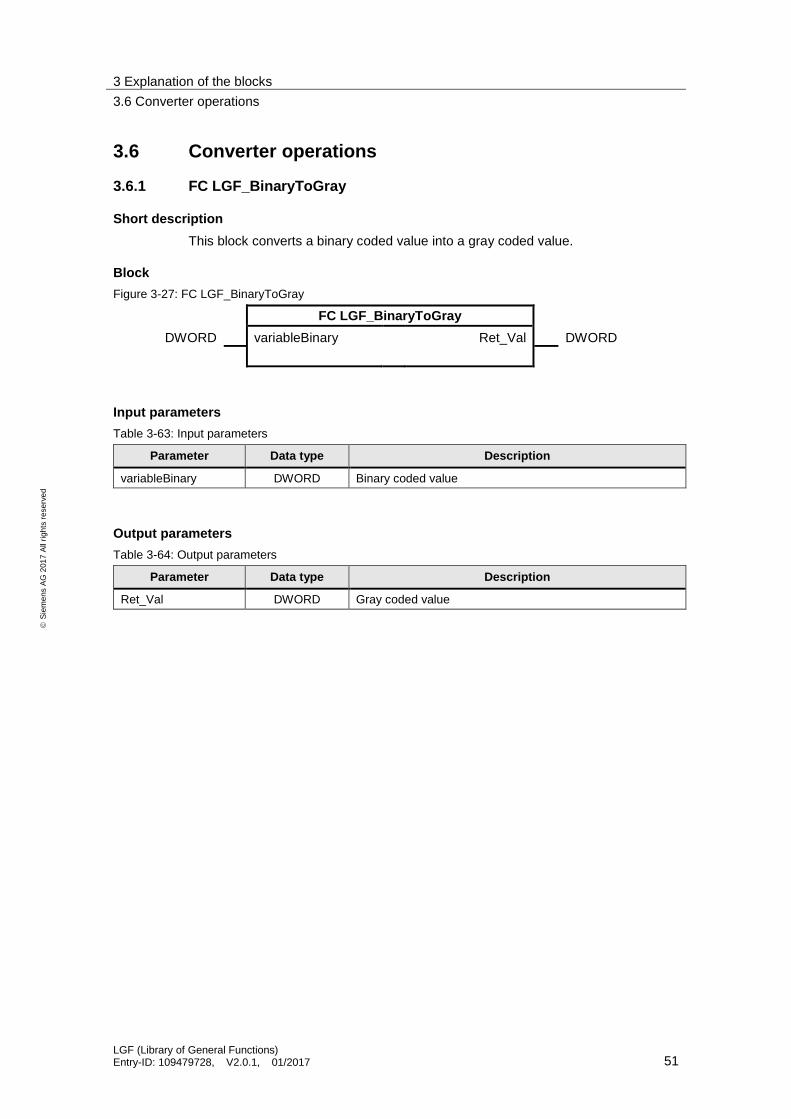
3 Explanation of the blocks
3.6 Converter operations
LGF (Library of General Functions) Entry-ID: 109479728, V2.0.1, 01/2017 51
S
iem
en
s A
G 2
01
7 A
ll ri
gh
ts r
ese
rve
d
3.6 Converter operations
3.6.1 FC LGF_BinaryToGray
Short description
This block converts a binary coded value into a gray coded value.
Block
Figure 3-27: FC LGF_BinaryToGray
FC LGF_BinaryToGray
DWORD variableBinary Ret_Val DWORD
Input parameters
Table 3-63: Input parameters
Parameter Data type Description
variableBinary DWORD Binary coded value
Output parameters
Table 3-64: Output parameters
Parameter Data type Description
Ret_Val DWORD Gray coded value

3 Explanation of the blocks
3.6 Converter operations
LGF (Library of General Functions) Entry-ID: 109479728, V2.0.1, 01/2017 52
S
iem
en
s A
G 2
01
7 A
ll ri
gh
ts r
ese
rve
d
3.6.2 FC LGF_GrayToBinary
Short description
This block converts a gray coded value into a binary coded value.
Block
Figure 3-28: FC LGF_GrayToBinary
FC LGF_GrayToBinary
DWORD variableGray Ret_Val DWORD
Input parameters
Table 3-65: Input parameters
Parameter Data type Description
variableGray DWORD Gray coded value
Output parameters
Table 3-66: Output parameters
Parameter Data type Description
Ret_Val DWORD Binary coded value

3 Explanation of the blocks
3.6 Converter operations
LGF (Library of General Functions) Entry-ID: 109479728, V2.0.1, 01/2017 53
S
iem
en
s A
G 2
01
7 A
ll ri
gh
ts r
ese
rve
d
3.6.3 FC LGF_DTLtoString
Short description
This block converts a date of the DTL data type into a character string of the STRING data type.
Block
Figure 3-29: FC LGF_DTLtoString
FC DTLtoString
DTL inDTL Ret_Val STRING
BOOL format
CHAR separatorDate
Input parameters
Table 3-67: Input parameters
Parameter Data type Description
inDTL DTL Date
format BOOL Format selection of the displayed character string:
0: international (YYYY MM DD ...)
1: traditional (DD MM YYYY ...)
separatorDate CHAR Separator between the components of the displayed date.
Output parameters
Table 3-68: Output parameters
Parameter Data type Description
Ret_Val STRING Displayed character string
Mode of operation
The block reads a date of the DTL data type, converts the date’s individual components (year, month, day, hour...) into a character string and outputs it. The individual components are placed at the correct position in the character string according to the format selection. The separator between the date’s components is variable.
Format selection
Via the “format” input parameter, you can select between the international (ISO 8601) and the traditional (DE) date format for the returned character string.
1. International format (ISO 8601) If the “format” input parameter has not been set (format = FALSE), the date is returned as character string in the international format. Example: 2016-03-16 13:34:12.123456789

3 Explanation of the blocks
3.6 Converter operations
LGF (Library of General Functions) Entry-ID: 109479728, V2.0.1, 01/2017 54
S
iem
en
s A
G 2
01
7 A
ll ri
gh
ts r
ese
rve
d
The following figure shows the position of the individual characters in the character string.
Figure 3-4: Position of the individual characters
2. Traditional format (ISO 8601) If the “format” input parameter has been set (format = TRUE), the date is returned as character string in the traditional format. Example: 16-03-2016 13:34:12.123456789 The following figure shows the position of the individual characters in the character string.
Figure 3-30: Position of the individual characters
Separator
At the “separatorDate” input parameter, you have to specify the separator between the components of the calendar date.
Example: separatorDate = ‘/’ outString = ‘2016/03/16 …’ separatorDate = ‘-‘ outString = ‘2016-03-16 …’

3 Explanation of the blocks
3.6 Converter operations
LGF (Library of General Functions) Entry-ID: 109479728, V2.0.1, 01/2017 55
S
iem
en
s A
G 2
01
7 A
ll ri
gh
ts r
ese
rve
d
3.6.4 FC LGF_StringToDTL
Short description
This block converts a character string of the String format with date components into the DTL data type.
Block
Figure 3-31: FC LGF_StringToDTL
FC LGF_StringToDTL
STRING inString Ret_Val DTL
BOOL format error Bool
status WORD
Input parameters
Table 3-7: Input parameters
Parameter Data type Description
inString STRING Date as character string
format BOOL Format selection of the read in character string:
0: international (YYYY MM DD ...)
1: traditional (DD MM YYYY ...)
Output parameters
Table 3-8: Output parameters
Parameter Data type Description
Ret_Val DTL Returns the read in date
error BOOL 0: no error
1: Block error, “status” returns error code
status WORD “status” returns the status/error code (see table below)
Status and error displays
Table 3-9: Status / Error codes
Status Meaning Remedy / Notes
16#0000 No errors -
16#7000 Initial value -
16#8201 Format: Year Year specification does not correspond to format or specification (outside the value range of DTL)
16#8202 Format: Month Month specification does not correspond to format or specification (outside the value range of DTL)
16#8203 Format: Day Day specification does not correspond to format or specification (outside the value range of DTL)

3 Explanation of the blocks
3.6 Converter operations
LGF (Library of General Functions) Entry-ID: 109479728, V2.0.1, 01/2017 56
S
iem
en
s A
G 2
01
7 A
ll ri
gh
ts r
ese
rve
d
Status Meaning Remedy / Notes
16#8204 Format: Hour Hour specification does not correspond to format or specification (outside the value range of DTL)
16#8205 Format: Minute Minute specification does not correspond to format or specification (outside the value range of DTL)
16#8206 Format: Second Second specification does not correspond to format or specification (outside the value range of DTL)
16#8207 Format: Nanosecond
Nanosecond specification does not correspond to format or specification (outside the value range of DTL)
Mode of operation
This block reads in a date as character string and converts it into the DTL data type. The individual date components in the character string are separated according to the format selection (positioning of data components in the character string). In this, the separator between the components in the character string is irrelevant.
Format selection
Via the “format” input parameter, you select, whether the read in character string is specified in the international (ISO 8601) or traditional (DE) data format.
1. International format (ISO 8601) If the “format” input parameter has not been set (format = FALSE), the date in the character string is read in in the international format. Example: inString = `2016-03-16 13:34:12.001` format = FALSE outDTL = DTL#2016-03-16-13:34:12.001000 Figure 2-10 shows the position of the individual characters in the character string.
Figure 3-10: Position of the individual characters
2. Traditional format (ISO 8601) If the “format” input parameter has been set (format = TRUE), the date in the character string is read in in the traditional format. Example: inString = ‘16/03/2016 13:34:12.1‘ format = TRUE outDTL = DTL#2016-03-16-13:34:12.100000 The following figure shows the position of the individual characters in the character string.
Figure 3-11: Position of the individual characters

3 Explanation of the blocks
3.6 Converter operations
LGF (Library of General Functions) Entry-ID: 109479728, V2.0.1, 01/2017 57
S
iem
en
s A
G 2
01
7 A
ll ri
gh
ts r
ese
rve
d
3.6.5 FC LGF_TemperatureConvert
Short description
This block converts °Celsius to °Fahrenheit or Kelvin, as well as °Fahrenheit to Kelvin and vice versa.
Block
Figure 3-32: FC LGF_TemperatureConvert
FC LGF_TemperatureConvert
INT mode Ret_Val REAL
REAL temperature error BOOL
Status WORD
Input parameters
Table 3-69: Input parameters
Parameter Data type Description
mode INT Mode
1. °Celsius to °Fahrenheit
2. °Fahrenheit to °Celsius
3. °Celsius to Kelvin
4. Kelvin to °Celsius
5. °Fahrenheit to Kelvin
6. Kelvin to °Fahrenheit
temperature REAL Temperature to be converted
Output parameters
Table 3-70: Output parameters
Parameter Data type Description
Ret_Val REAL Converted temperature
error BOOL 0: no errors
1: Block errors
status WORD “status” returns the status/error code (see table below).
Status and error displays
Table 3-71: Status / Error codes
Status Meaning Remedy / Notes
16#7000 Initial value -
16#0000 No errors -
16#8200 Incorrect mode at “mode” input. See description of input parameters

3 Explanation of the blocks
3.7 Signal generators
LGF (Library of General Functions) Entry-ID: 109479728, V2.0.1, 01/2017 58
S
iem
en
s A
G 2
01
7 A
ll ri
gh
ts r
ese
rve
d
3.7 Signal generators
3.7.1 FB LGF_Frequency
Short description
The block generates a signal which, depending on a defined frequency and a pulse-to-pause ratio, switches between the values “0” and “1”.
Block
Figure 3-33: FB LGF_Frequency
FB LGF_Frequency
REAL frequency clock BOOL
REAL pulsePauseRatio countdown TIME
Input parameters
Table 3-72: Input parameters
Parameter Data type Description
frequency REAL Clock frequency in Hz
pulsePauseRatio REAL Pulse-pause ratio (Default: 1.0 equals 1:1)
Output parameters
Table 3-73: Output parameters
Parameter Data type Description
clock BOOL Output switches with defined frequency
countdown TIME Remaining time of current “clock” status
Mode of operation
The “clock” output is a Boolean value that toggles in the desired frequency. Via the “pulsePauseRatio“ input, the pulse-pause ratio is set.
The “Countdown” output outputs the remaining time of the current state of “clock”.
If the desired frequency or pulse-pause ratio is smaller than or equal to 0.0, then the “clock” output = FALSE and “countdown” = “0 s”.

3 Explanation of the blocks
3.7 Signal generators
LGF (Library of General Functions) Entry-ID: 109479728, V2.0.1, 01/2017 59
S
iem
en
s A
G 2
01
7 A
ll ri
gh
ts r
ese
rve
d
Example
Figure 3-34: FB LGF_Frequency
T#0S_703MS
TRUE
T = 2 ston = 1.5 stoff = 0.5 s
FB LGF_Frequency
frequency clock
countdown
0.5
pulsePauseRatio3.0
Tton toff
clock
�𝑢𝑙 𝑒𝑃𝑎𝑢 𝑒𝑅𝑎𝑡 𝑜 = 𝑡𝑜
𝑡𝑜 = 1:3

3 Explanation of the blocks
3.7 Signal generators
LGF (Library of General Functions) Entry-ID: 109479728, V2.0.1, 01/2017 60
S
iem
en
s A
G 2
01
7 A
ll ri
gh
ts r
ese
rve
d
3.7.2 FB LGF_Impulse
Short description
This block generates impulses in a predefined frequency. The impulse is always available for a (controller) cycle.
Block
Figure 3-35: FB LGF_Impulse
FB LGF_Impulse
REAL frequency impulse BOOL
countdown TIME
Input parameters
Table 3-74: Input parameters
Parameter Data type Description
frequency REAL Clock speed
Output parameters
Table 3-75: Output parameters
Parameter Data type Description
impulse BOOL Signal with impulses
countdown TIME Time until next impulse
Mode of operation
The block generates impulses at the “impulse” output with the frequency “frequency”.
The frequency is implemented via the “LGF_Frequency“ block. If there is a negative edge at the “clock” output of the “LGF_Frequency” block, an impulse is generated at the “impulse” output.
Example
Figure 3-36
TRUE
Period duration: 2 seconds
FB LGF_Impulse
frequency
impulse
countdown
0.5
T#0S_703MS
Note For the block to work, the “LGF_Frequency“ block additionally needs to be included into the STEP7 project.

3 Explanation of the blocks
3.7 Signal generators
LGF (Library of General Functions) Entry-ID: 109479728, V2.0.1, 01/2017 61
S
iem
en
s A
G 2
01
7 A
ll ri
gh
ts r
ese
rve
d
3.7.3 FB LGF_SawTooth
Short description
This block generates a sawtooth-shaped signal path. Every sawtooth consists of a defined number of steps (increments).
Block
Figure 3-37: FB LGF_SawTooth
FB LGF_SawTooth
INT startValue value INT
TIME timeRange
INT incrementRange
INT numberSteps
BOOL endlessSteps
BOOL restart
Input parameters
Table 3-76: Input parameters
Parameter Data type Description
startValue INT Start value at the the signal starts.
timeRange TIME Time, after which the “value” output parameter is incremented
incrementRange INT Size of jump from one increment to the next.
numberSteps INT Number of increments per sawtooth. (In case of an endless sawtooth-signal, this specification is not required).
endlessSteps BOOL Specification, whether an endless sawtooth-signal shall be generated.
restart BOOL Sawtooth-signal restarts at start value “start value”.
Note Note that changes to the input parameters only become effective upon “restart”.
Output parameters
Table 3-77: Output parameters
Parameter Data type Description
value INT Current value of the sawtooth-signal.
Mode of operation
The block calculates the values for a sawtooth-shaped signal path which are output at the “value” output parameter. The signal starts with the start value “startValue”

3 Explanation of the blocks
3.7 Signal generators
LGF (Library of General Functions) Entry-ID: 109479728, V2.0.1, 01/2017 62
S
iem
en
s A
G 2
01
7 A
ll ri
gh
ts r
ese
rve
d
and is added up with the “increment” value every time the “timeRange” time interval expires. The value can also be negative.
If the “endlessSteps” tag is set to “FALSE”, the number of summation steps is counted. If it exceeds the “numberSteps” value, then the output parameter “value” is reset to the start value. A new sawtooth starts.
If the “endlessSteps” tag is set to “TRUE”, then - once beginning at “startValue” - the “increment” value is continuously added up. If the maximum positive INT value range (32767) of the “value” output parameter is exceeded, “value” switches to the maximum negative INT value range (-32768) and is continuously added up.
Note The duration of a sawtooth with “endlessSteps” on “FALSE” is calculated as follows:
Duration = „timeRange * („numberSteps“ + 1)
Figure 3-38: Signal path of “value” output
startValue
incrementRange
timeRange
time
value
endless Steps= true
restart = true
restart = false

3 Explanation of the blocks
3.8 Technology operations
LGF (Library of General Functions) Entry-ID: 109479728, V2.0.1, 01/2017 63
S
iem
en
s A
G 2
01
7 A
ll ri
gh
ts r
ese
rve
d
3.8 Technology operations
3.8.1 FB LGF_LimRateOfChangeBasic
Short description
This block limits the rate of change of an input value. A jump function turns into a ramp function.
Block
Figure 3-39: FB LGF_LimRateOfChangeBasic
FB LGF_LimRateOfChangeBasic
REAL inputValue outputValue REAL
REAL setRateLim error BOOL
REAL defaultOutValue statusID UINT
BOOL onDefaultOutValue status WORD
OB_CYCLIC callOB
Input parameters
Table 3-78: Input parameters
Parameter Data type Description
inputValue REAL Input value (jump function)
setRateLim REAL Rate of change of ramp function (1/second)
onDefaultOutValue BOOL Preset output value
dafaultOutValue REAL Value for the preset output value
callOB OB_CYCLIC Calling cyclic interrupt OB
Output parameters
Table 3-79: Output parameters
Parameter Data type Description
outputValue REAL Output value
error BOOL 0: no errors
1: Block error, “statusID” returns error source, “status” returns error code
statusID UINT “statusID” returns the ID of the block reporting the status. See table below.
status WORD “status” returns the status/error code (see table below)

3 Explanation of the blocks
3.8 Technology operations
LGF (Library of General Functions) Entry-ID: 109479728, V2.0.1, 01/2017 64
S
iem
en
s A
G 2
01
7 A
ll ri
gh
ts r
ese
rve
d
Status and error displays
Table 3-80: Status / Error codes
statusID status Meaning Remedy / Notes
1 16#0000 No errors -
1 16#7000 Initial value “onDefaultOutValue“ active
1 16#8200 OB at “callOB” input is not configured/present.
At the “calIOB” input, connect a configured/present cyclic interrupt OB
1 16#8201 Negative rate of change. The parameter for the rate of change must not be negative
2 - Error/status of subordinate function “QRY_CINT” while querying the cyclic interrupt parameters.
Possible cause: OB at “callOB“ input is of the wrong type
Note If “statusID” is > 1, all values of the “status” output came directly from called up instructions (see table on output parameters). In this case, get the information on the respective instructions from the TIA Portal Online Help.
Mode of operation
The ramp is a limitation line and refers to a change of rate per second; if “setRateLim = 10.0“ is parameterized, for example, then at a sampling time of 1s/100ms/10ms and if “inputValue > outputValue“ is set, 10.0/1.0/0.1 are added to “outputValue“ during each block call, until “inputValue” has been reached.
The limitation of the change of rate is valid for the increase and the decrease in both, the positive and the negative value range.
The “outputValue” output can be preset or initialized.
The time interval of the calling cycle interrupt OB is detected by connecting the calling cycle interrupt OB at the “callOB” input parameter.
Figure 3-40: Connect cyclic interrupt OB
Presetting the output
If “onDefaultOutValue = TRUE“ is set, then “defaultOutValue” is the active output; upon switching from TRUE to FALSE, “outputValue” is run as a ramp from “outputValue” to “inputValue”. Upon switching from FALSE to TRUE, the “outputValue” output immediately switches to “defaultOutValue”.

3 Explanation of the blocks
3.8 Technology operations
LGF (Library of General Functions) Entry-ID: 109479728, V2.0.1, 01/2017 65
S
iem
en
s A
G 2
01
7 A
ll ri
gh
ts r
ese
rve
d
Function growth
Figure 3-41: Ramp function growth
defaultOutValue
t
outputValue
inputValue (t)
onDefaultOutValue
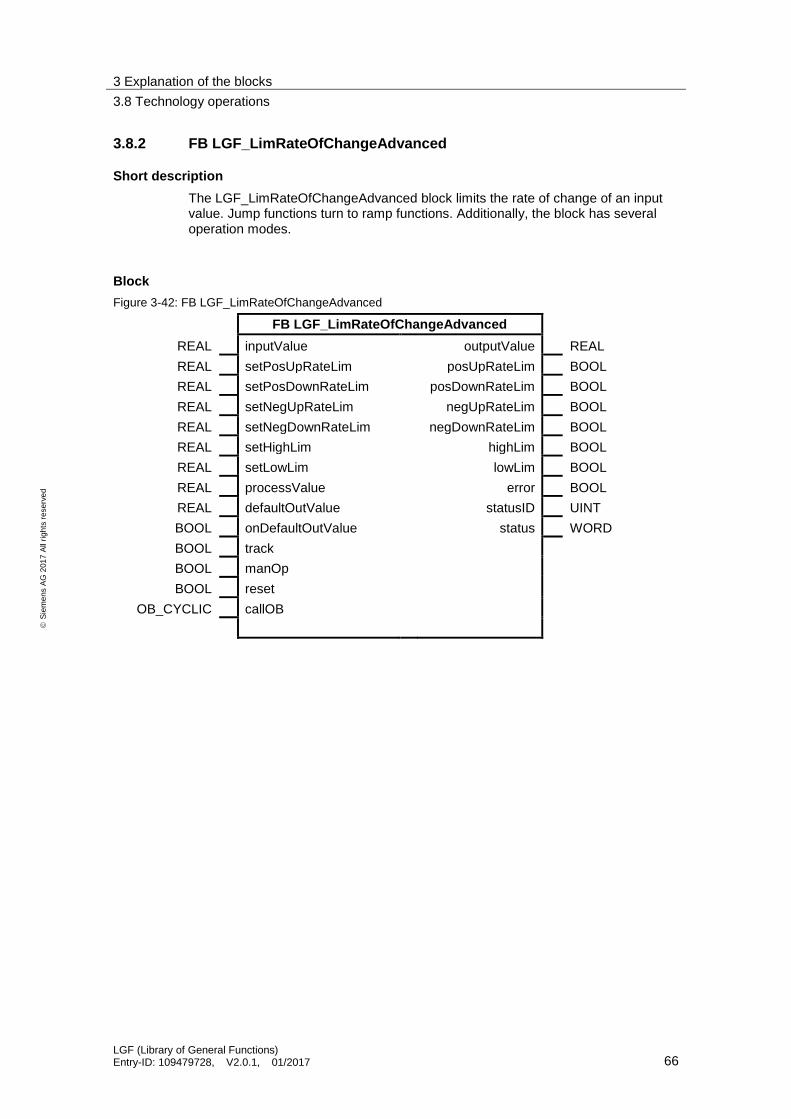
3 Explanation of the blocks
3.8 Technology operations
LGF (Library of General Functions) Entry-ID: 109479728, V2.0.1, 01/2017 66
S
iem
en
s A
G 2
01
7 A
ll ri
gh
ts r
ese
rve
d
3.8.2 FB LGF_LimRateOfChangeAdvanced
Short description
The LGF_LimRateOfChangeAdvanced block limits the rate of change of an input value. Jump functions turn to ramp functions. Additionally, the block has several operation modes.
Block
Figure 3-42: FB LGF_LimRateOfChangeAdvanced
FB LGF_LimRateOfChangeAdvanced
REAL inputValue outputValue REAL
REAL setPosUpRateLim posUpRateLim BOOL
REAL setPosDownRateLim posDownRateLim BOOL
REAL setNegUpRateLim negUpRateLim BOOL
REAL setNegDownRateLim negDownRateLim BOOL
REAL setHighLim highLim BOOL
REAL setLowLim lowLim BOOL
REAL processValue error BOOL
REAL defaultOutValue statusID UINT
BOOL onDefaultOutValue status WORD
BOOL track
BOOL manOp
BOOL reset
OB_CYCLIC callOB
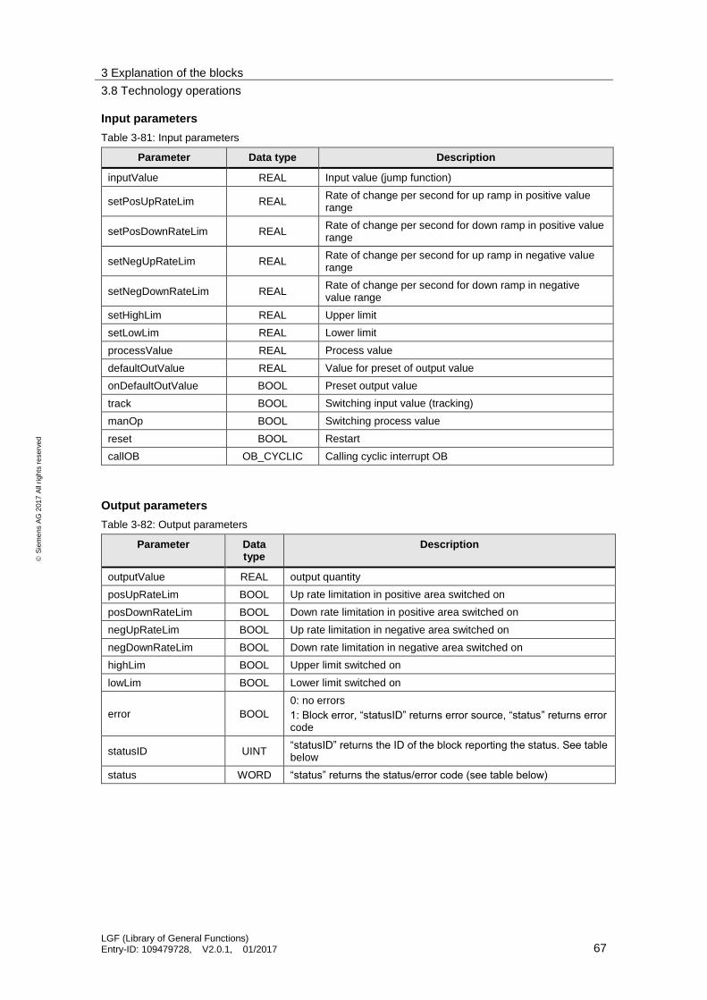
3 Explanation of the blocks
3.8 Technology operations
LGF (Library of General Functions) Entry-ID: 109479728, V2.0.1, 01/2017 67
S
iem
en
s A
G 2
01
7 A
ll ri
gh
ts r
ese
rve
d
Input parameters
Table 3-81: Input parameters
Parameter Data type Description
inputValue REAL Input value (jump function)
setPosUpRateLim REAL Rate of change per second for up ramp in positive value range
setPosDownRateLim REAL Rate of change per second for down ramp in positive value range
setNegUpRateLim REAL Rate of change per second for up ramp in negative value range
setNegDownRateLim REAL Rate of change per second for down ramp in negative value range
setHighLim REAL Upper limit
setLowLim REAL Lower limit
processValue REAL Process value
defaultOutValue REAL Value for preset of output value
onDefaultOutValue BOOL Preset output value
track BOOL Switching input value (tracking)
manOp BOOL Switching process value
reset BOOL Restart
callOB OB_CYCLIC Calling cyclic interrupt OB
Output parameters
Table 3-82: Output parameters
Parameter Data type
Description
outputValue REAL output quantity
posUpRateLim BOOL Up rate limitation in positive area switched on
posDownRateLim BOOL Down rate limitation in positive area switched on
negUpRateLim BOOL Up rate limitation in negative area switched on
negDownRateLim BOOL Down rate limitation in negative area switched on
highLim BOOL Upper limit switched on
lowLim BOOL Lower limit switched on
error BOOL
0: no errors
1: Block error, “statusID” returns error source, “status” returns error code
statusID UINT “statusID” returns the ID of the block reporting the status. See table below
status WORD “status” returns the status/error code (see table below)

3 Explanation of the blocks
3.8 Technology operations
LGF (Library of General Functions) Entry-ID: 109479728, V2.0.1, 01/2017 68
S
iem
en
s A
G 2
01
7 A
ll ri
gh
ts r
ese
rve
d
Status and error displays
Table 3-83: Status / Error codes
statusID status Meaning Remedy / Notes
1 16#0000 No errors -
1 16#8200 OB at “callOB” input is not configured/present.
At the “calIOB” input, connect a configured/present cyclic interrupt OB.
1 16#8201 “setHighLim“ < “setLowLim“ Upper limit “setHighLim” needs to be greater than the lower limit “setLowLim”.
1 16#8202 Negative rate of change. The parameters for the rate of change must only be >= 0.0.
2 - Error/status of subordinate function “QRY_CINT” while querying the cyclic interrupt parameters.
Possible cause: OB at “callOB“ input is of the wrong type.
Note If “statusID” is > 1, all values of the “status” output came directly from called up instructions (see table on output parameters). In this case, get the information on the respective instructions from the TIA Portal Online Help.
Mode of operation
For the positive/negative value range, two rates of change are parametrizable for the ramp (rising and falling values). Via controller inputs, the following operation modes can be selected:
Restart
Presetting the output
Normal operation (automatic)
Tracking
Switching process value (manual)
The output value can be limited via two parametrizable limits. An active limitation of the rate of change of a ramp as well as an active limitation of the output value are reported via the outputs.
The time interval of the calling cycle interrupt OB is detected by connecting the calling cycle interrupt OB at the “callOB” input parameter.
Figure 3-43: Connect cyclic interrupt OB

3 Explanation of the blocks
3.8 Technology operations
LGF (Library of General Functions) Entry-ID: 109479728, V2.0.1, 01/2017 69
S
iem
en
s A
G 2
01
7 A
ll ri
gh
ts r
ese
rve
d
Restart
Upon restart “reset = TRUE”, the output “outputValue” is reset to 0.0. If “onDefaultOutValue = TRUE“ is set, “defaultOutValue” is output. All signal outputs are set to FALSE.
Presetting the output
If “onDefaultOutValue = TRUE“ is set, then “defaultOutValue” is the active output; upon switching from TRUE to FALSE, “outputValue” is run as a ramp from “outputValue” to “inputValue”. Upon switching from FALSE to TRUE, the “outputValue” output immediately switches to “defaultOutValue”.
Normal operation
The ramps are a limitation lines and refer to a change of rate per second; if “setPosUpRateLim = 10.0“ is parameterized, for example, then at a sampling time of 1s/100ms/10ms and if “inputValue > outputValue“ is set, 10.0/1.0/0.1 are added to “outputValue“ during each block call, until “inputValue” has been reached.
The limitation of the change of rate is parametrizable for the rise and the fall in both, the positive and the negative value range.
Table 3-84: Marking of ramps
Parameter Ramp
setPosUpRateLim outputValue > 0 and |outputValue| ascending
setPosDownRateLim outputValue > 0 and |outputValue| descending
setNegUpRateLim outputValue < 0 and |outputValue| ascending
setNegDownRateLim outputValue < 0 and |outputValue| descending
If the ramps are not parameterized (”setPosUpRateLim“, “setPosDownRateLim“, “setNegUpRateLim“ and “setNegDownRateLim“ are 0.0), then the output remains at a value of 0.0 and normal operation is not functioning.
Tracking
If the input “track = TRUE“ is set, the input value “inputValue” is switched directly to the output value “outputValue”. Thus, jumps of the input value are also output.
Switching process value
If “manOp = TRUE“ is set, the process value “processValue” is switched directly to the output value “outputValue”.
In this operation mode, the parameterization of the ramps or the upper/lower limits of the output value and the preset of the output are ineffective.
Upon switching from TRUE to FALSE, the output “outputValue” is once more run as a ramp to “inputValue”.
As soon as the value section between the lower and the upper limitation has been reached, the upper and lower limitation is reactivated.

3 Explanation of the blocks
3.8 Technology operations
LGF (Library of General Functions) Entry-ID: 109479728, V2.0.1, 01/2017 70
S
iem
en
s A
G 2
01
7 A
ll ri
gh
ts r
ese
rve
d
Function growth
Figure 3-44: Ramp function
setHighLiminputValue (t)
setLowLim
processValue (t)
t
outputValue
defaultOutValue
highLim
posNegRateLim
lowLim
posUpRateLim
negDownRateLim
negUpRateLim
manOp
track
onDefaultOutValue

4 References
LGF (Library of General Functions) Entry-ID: 109479728, V2.0.1, 01/2017 71
S
iem
en
s A
G 2
01
7 A
ll ri
gh
ts r
ese
rve
d
4 References
Table 4-1: References
Topic Title
\1\ Siemens Industry Online Support
http://support.automation.siemens.com
\2\ Download page of the entry https://support.industry.siemens.com/cs/ww/en/view/109479728
\3\ Programming guide and programming style guide
https://support.industry.siemens.com/cs/ww/en/view/81318674
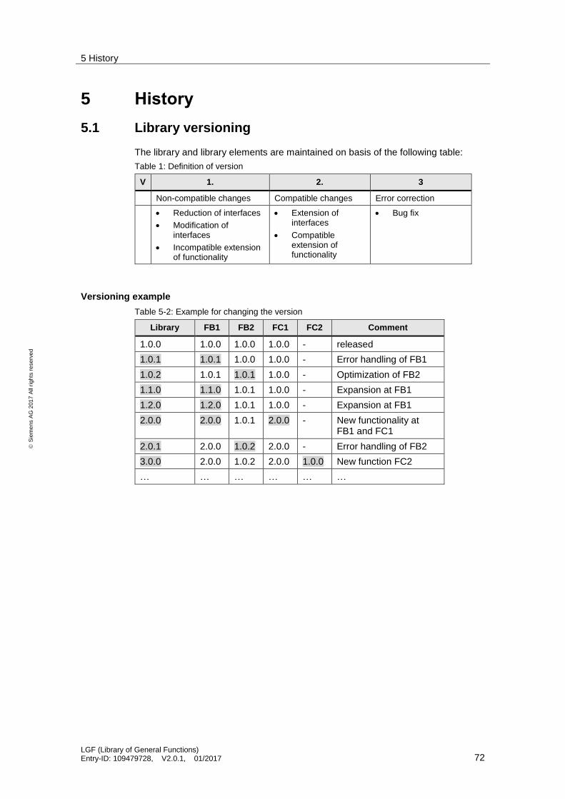
5 History
LGF (Library of General Functions) Entry-ID: 109479728, V2.0.1, 01/2017 72
S
iem
en
s A
G 2
01
7 A
ll ri
gh
ts r
ese
rve
d
5 History
5.1 Library versioning
The library and library elements are maintained on basis of the following table:
Table 1: Definition of version
V 1. 2. 3
Non-compatible changes Compatible changes Error correction
Reduction of interfaces
Modification of interfaces
Incompatible extension of functionality
Extension of interfaces
Compatible extension of functionality
Bug fix
Versioning example
Table 5-2: Example for changing the version
Library FB1 FB2 FC1 FC2 Comment
1.0.0 1.0.0 1.0.0 1.0.0 - released
1.0.1 1.0.1 1.0.0 1.0.0 - Error handling of FB1
1.0.2 1.0.1 1.0.1 1.0.0 - Optimization of FB2
1.1.0 1.1.0 1.0.1 1.0.0 - Expansion at FB1
1.2.0 1.2.0 1.0.1 1.0.0 - Expansion at FB1
2.0.0 2.0.0 1.0.1 2.0.0 - New functionality at FB1 and FC1
2.0.1 2.0.0 1.0.2 2.0.0 - Error handling of FB2
3.0.0 2.0.0 1.0.2 2.0.0 1.0.0 New function FC2
… … … … … …

5 History
LGF (Library of General Functions) Entry-ID: 109479728, V2.0.1, 01/2017 73
S
iem
en
s A
G 2
01
7 A
ll ri
gh
ts r
ese
rve
d
5.2 Change log
Table 5-3 : Change log
Version Date Modifications
V1.0.0 09/2015 First version
V1.0.1 10/2015 LGF_Astro V1.0.1
T_ADD instruction replaced by “+”.
V1.0.2 10/2015 LGF_BinaryToGray V1.0.1
Name changed
LGF_GrayToBinary V1.0.1
Name changed
V1.0.3 11/2015 LGF_CompareVariant V1.0.1
Error correction
V1.0.4 11/2015 LGF_SawTooth V1.0.1
Error correction
V1.0.5 11/2015 LGF_Astro V1.0.2
Error correction
LGF_AverageAndDeviation V1.0.1
Error correction
LGF_TimerSwitch V1.0.1
Error correction
LGF_FIFO V1.0.1
Error correction
V2.0 07/2016 New:
Chapter 1.3 Library resources
FB LGF_PulseRelay V1.0.0
FB LGF_SetTime V1.0.0
FB LGF_FloatingAverage V1.0.0
FC LGF_DTLtoString V1.0.0
FC LGF_StringToDTL V1.0.0
FB LGF_LimRateOfChangeBasic V1.0.0
FB LGF_LimRateOfChangeAdvanced V1.0.0
Revised:
LGF_Astro V1.1.1
systemTime and localTime outputs added
FB LGF_TimerSwitch V1.1.0
Two new modes: Weekday, weekend
FB LGF_ShallSort… V1.1.0
New mode: Sort in descending order
FB LGF_Frequency V1.1.0
New function: Pulse-pause ratio adjustable
FB LGF_Impulse V1.1.0
Calls new LGF_Frequency V1.1.0.
V2.0.1 01/2017 Revised:
LGF_Astro V1.1.2
Error correction at calculation of sunrise and sunset