Embed Size (px)
Citation preview
NYOTA 115
Electro-mechanical sliding gate operator
GBInstruction manual
FIXING BRACKET SET INTOA CONCRETE FOUNDATION
SPIRIT LEVEL
SPIRIT LEVEL
2
INSTRUCTIONS FOR THE INSTALLATION OF THE AUTOMATION
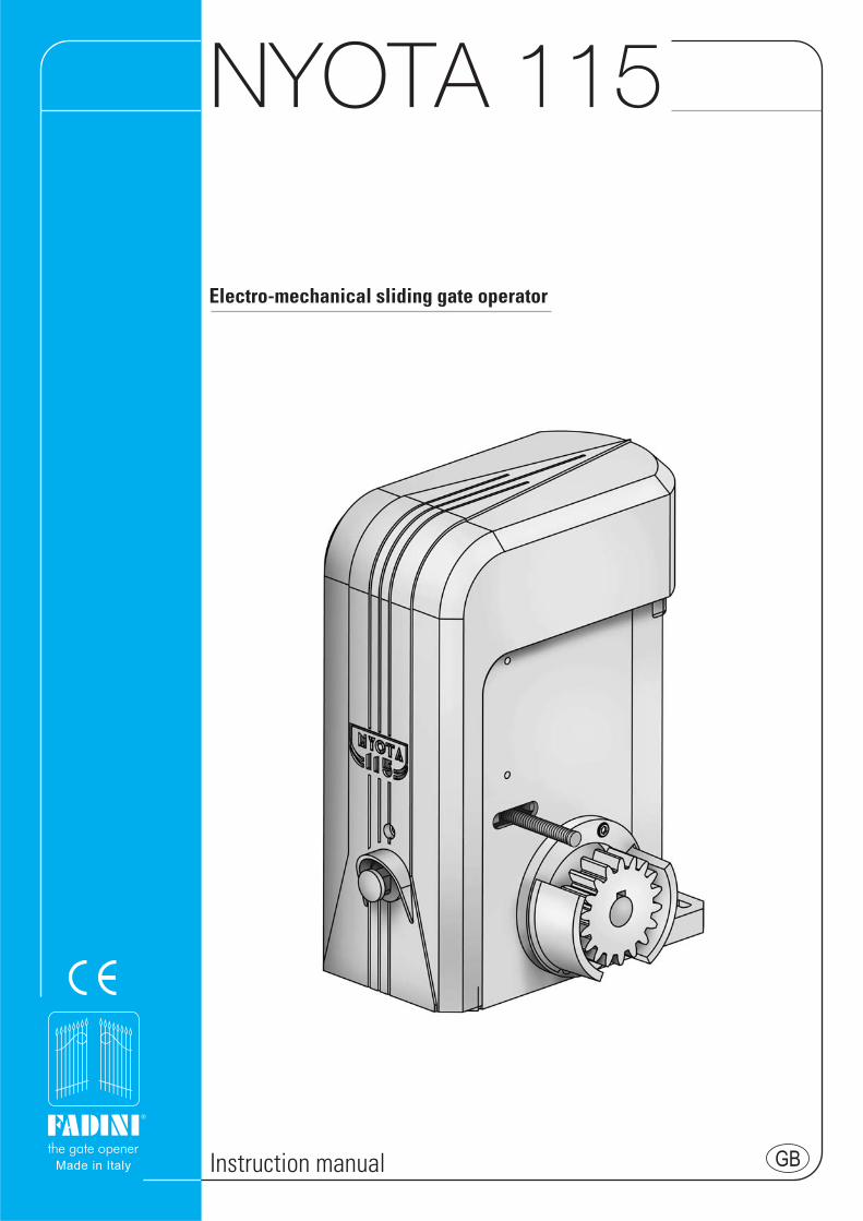
FOR A CORRECT INSTALLATION AND GOOD PERFORMANCE OF NYOTA 115 READ THE INSTRUCTIONS THAT ARE OUTLINED IN THISMANUAL AND KEEP TO THE DIAGRAMS.Nyota 115 is an extremely versatile system for sliding gates up to 1˙200 Kg gate weight. It is available in 0.37 KW (0.5 HP) single- and three-phase versions and 0.73 KW (1.0 HP) single and three-phase versions.It is a strong and reliable automation. It has a torque control device that can be manually adjusted; worm and gear are made of bronzeand steel and are supported by bearings, all these parts in an oil bath. A manual overriding system allows manual operations of the gatein emergency events like power failure.
POINTS TO CHECK WITH THE GATECheck that the gate track is well fixed to a solid foundation to preventdeformation which would result into an unbalanced travelling of the gate.IMPORTANT: Make sure that gate stops are fixed in the fully open andfully closed gate positions so that the gate does not over travel thepermitted limit and go out of the upper guide.IMPORTANT: Make sure that, once at the end of the permitted travel, thegate does not hit the gate posts or specially fitted gate stops to avoiddamages to its structure.
FITTING NYOTA 115 ONTO THE FIXING BASE PLATE- The first operation is to fix the fixing bracket to the ground and make
sure that it is perfectly levelled. Fixing distances are as indicated (pic.1).Fixing is by setting the plate into a concrete foundation.
- Remove the cover of NYOTA 115 by loosening the fixing screw-A (or bythe optional key): pull the cover outwards and almost simultaneouslyupwards (pic.2).
- NYOTA 115 is fixed to the bracket by four screws-B (pic.3)
PIC. 1
PIC. 2
PIC. 3
RACK FITTING OPERATIONS
IMPORTANT: When installing NYOTA 115 it is recommended to insert2 mm shims between the fixing bracket and the NYOTA 115 base plate(NYOTA 115 perfectly levelled) before welding the rack to the gate, sothat the rack and gear mesh each other with an adequate clearanceafter that the shims have been removed (pic.3).- Temporarily fix NYOTA 115 onto the fixing bracket, perfectly levelled,
by the four fixing screws-B (pic.3).
PULL OUTWARDS
COVER FIXINGSCREW-A
LOCK ANDKEY
FIXINGSCREWS-B
2 mm SHIMS TO REMOVEAFTER FIXING THE RACKTO THE GATE
NYOTA 115
®
3
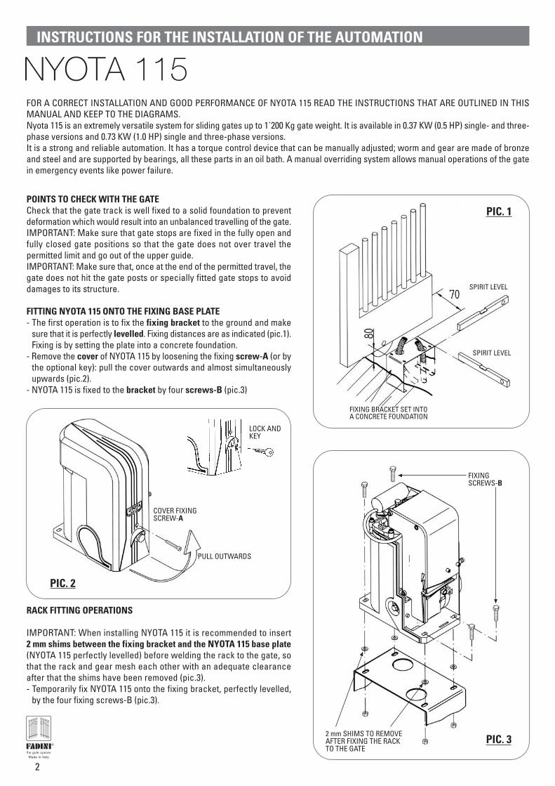
- How to release NYOTA 115 from the gate and disconnect the driving gear: remove the cover (pic.2) and unscrew the hexagonal screw(by 1 or 2 turns maximum) by the release spanner E 13 supplied with the equipment (pic.4).
PIC. 4
PIC. 5
E13RELEASESPANNER
1-2 TURNS ANTI-CLOCKWISETO RELEASE
RELEASEHEXAGONALSCREW
DRIVING GEARIE. PINION
LIMIT SWITCHSTRIKING PLATE
A 15-20 mm CLEARANCE ISRECOMMENDED BETWEENNYOTA 115 AND LIMIT SWITCHSTRIKING PLATE SURFACELINE
RACK
- This explains how to fix the rack. Release the system by the provided E 13 spanner so that the driving gear of NYOTA 115 can run idle(pic. 4). (The gate can be freely moved by hand, the operator Nyota 115 standing in idle position).
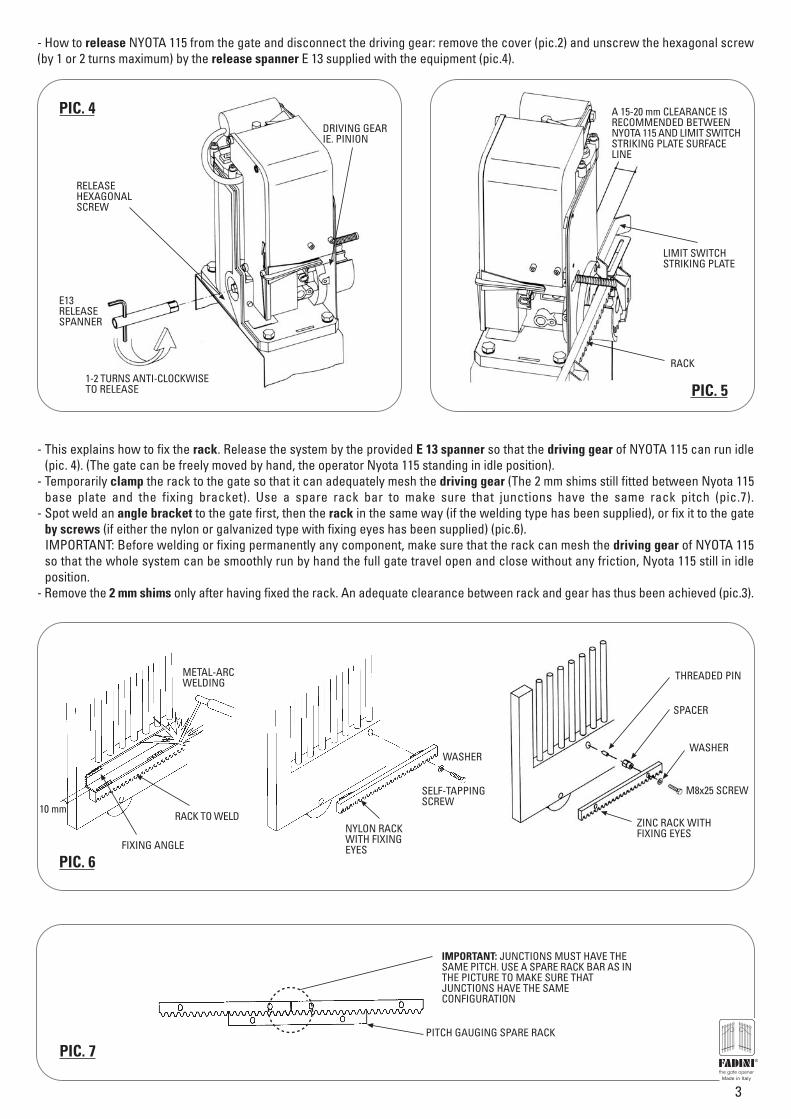
- Temporarily clamp the rack to the gate so that it can adequately mesh the driving gear (The 2 mm shims still fitted between Nyota 115base plate and the fixing bracket). Use a spare rack bar to make sure that junctions have the same rack pitch (pic.7).
- Spot weld an angle bracket to the gate first, then the rack in the same way (if the welding type has been supplied), or fix it to the gateby screws (if either the nylon or galvanized type with fixing eyes has been supplied) (pic.6).IMPORTANT: Before welding or fixing permanently any component, make sure that the rack can mesh the driving gear of NYOTA 115so that the whole system can be smoothly run by hand the full gate travel open and close without any friction, Nyota 115 still in idleposition.
- Remove the 2 mm shims only after having fixed the rack. An adequate clearance between rack and gear has thus been achieved (pic.3).
METAL-ARCWELDING
RACK TO WELD
THREADED PIN
SPACER
WASHER
M8x25 SCREW
ZINC RACK WITHFIXING EYES
FIXING ANGLE
NYLON RACKWITH FIXINGEYES
SELF-TAPPINGSCREW
WASHER
10 mm
PIC. 6
PIC. 7
IMPORTANT: JUNCTIONS MUST HAVE THESAME PITCH. USE A SPARE RACK BAR AS INTHE PICTURE TO MAKE SURE THATJUNCTIONS HAVE THE SAMECONFIGURATION
PITCH GAUGING SPARE RACK
®
4
PIC. 8
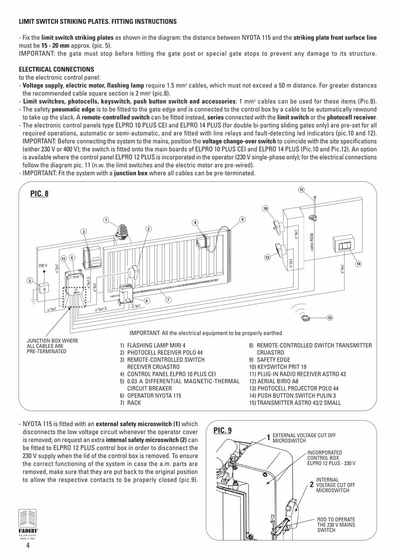
1) FLASHING LAMP MIRI 42) PHOTOCELL RECEIVER POLO 443) REMOTE-CONTROLLED SWITCH
RECEIVER CRUASTRO4) CONTROL PANEL ELPRO 10 PLUS CEI5) 0.03 A DIFFERENTIAL MAGNETIC-THERMAL
CIRCUIT BREAKER6) OPERATOR NYOTA 1157) RACK
8) REMOTE-CONTROLLED SWITCH TRANSMITTER CRUASTRO
9) SAFETY EDGE10) KEYSWITCH PRIT 1911) PLUG-IN RADIO RECEIVER ASTRO 4312) AERIAL BIRIO A813) PHOTOCELL PROJECTOR POLO 4414) PUSH BUTTON SWITCH PULIN 315) TRANSMITTER ASTRO 43/2 SMALL
- NYOTA 115 is fitted with an external safety microswitch (1) whichdisconnects the low voltage circuit whenever the operator coveris removed; on request an extra internal safety microswitch (2) canbe fitted to ELPRO 12 PLUS control box in order to disconnect the230 V supply when the lid of the control box is removed. To ensurethe correct functioning of the system in case the a.m. parts areremoved, make sure that they are put back to the original positionto allow the respective contacts to be properly closed (pic.9).
LIMIT SWITCH STRIKING PLATES. FITTING INSTRUCTIONS
- Fix the limit switch striking plates as shown in the diagram: the distance between NYOTA 115 and the striking plate front surface linemust be 15 - 20 mm approx. (pic. 5).IMPORTANT: the gate must stop before hitting the gate post or special gate stops to prevent any damage to its structure.
ELECTRICAL CONNECTIONSto the electronic control panel:- Voltage supply, electric motor, flashing lamp require 1.5 mm2 cables, which must not exceed a 50 m distance. For greater distances
the recommended cable square section is 2 mm2 (pic.8).- Limit switches, photocells, keyswitch, push button switch and accessories: 1 mm2 cables can be used for these items (Pic.8).- The safety pneumatic edge is to be fitted to the gate edge and is connected to the control box by a cable to be automatically rewound
to take up the slack. A remote-controlled switch can be fitted instead, series connected with the limit switch or the photocell receiver.- The electronic control panels type ELPRO 10 PLUS CEI and ELPRO 14 PLUS (for double bi-parting sliding gates only) are pre-set for all
required operations, automatic or semi-automatic, and are fitted with line relays and fault-detecting led indicators (pic.10 and 12).IMPORTANT: Before connecting the system to the mains, position the voltage change-over switch to coincide with the site specifications(either 230 V or 400 V); the switch is fitted onto the main boards of ELPRO 10 PLUS CEI and ELPRO 14 PLUS (Pic.10 and Pic.12). An optionis available where the control panel ELPRO 12 PLUS is incorporated in the operator (230 V single-phase only); for the electrical connectionsfollow the diagram pic. 11 (n.w. the limit switches and the electric motor are pre-wired).
- IMPORTANT: Fit the system with a junction box where all cables can be pre-terminated.
PIC. 9
INCORPORATEDCONTROL BOXELPRO 12 PLUS - 230 V
ROD TO OPERATETHE 230 V MAINSSWITCH
2
1 EXTERNAL VOLTAGE CUT OFFMICROSWITCH
INTERNALVOLTAGE CUT OFFMICROSWITCH
®
JUNCTION BOX WHEREALL CABLES AREPRE-TERMINATED
n°3x1,5 n°3x1
n°2x
1
n°4x
1,5
n°4x
1
230 V
n°4x1
n°2x
1n°
4x1
cabl
e RG
58
n°4x
1
1
2
6 7
98
10
13
3
414
5
11
12
IMPORTANT: All the electrical equipment to be properly earthed
15
5
Drwg. No. 4333
SINGLE- AND THREE-PHASE FOR SLIDING GATESAND AUTOMATIONS FITTED WITH LIMIT SWITCHES10 PLUS CEIGB
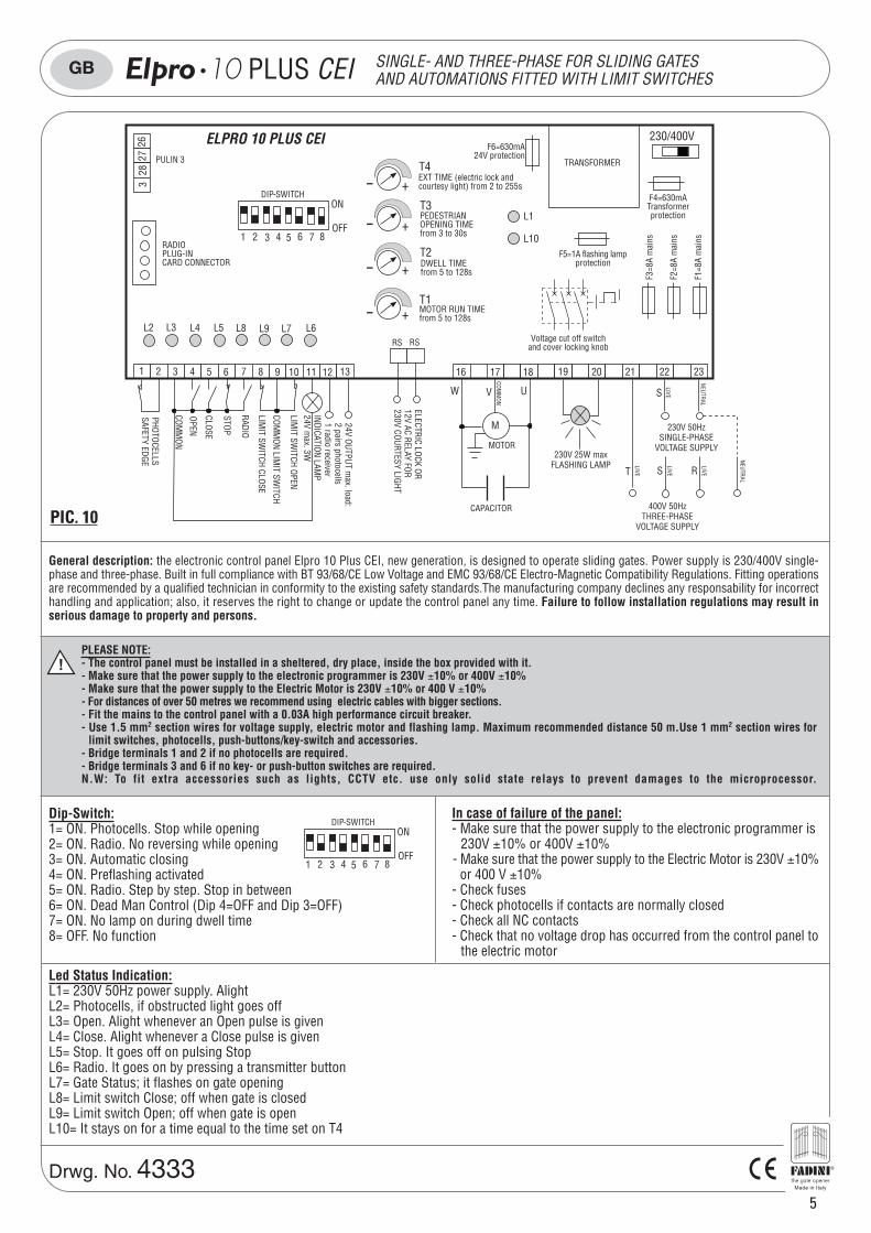
General description: the electronic control panel Elpro 10 Plus CEI, new generation, is designed to operate sliding gates. Power supply is 230/400V single-phase and three-phase. Built in full compliance with BT 93/68/CE Low Voltage and EMC 93/68/CE Electro-Magnetic Compatibility Regulations. Fitting operationsare recommended by a qualified technician in conformity to the existing safety standards.The manufacturing company declines any responsability for incorrecthandling and application; also, it reserves the right to change or update the control panel any time. Failure to follow installation regulations may result inserious damage to property and persons.
T S R
PULIN 3
2627
283
DIP-SWITCHON
OFF1 4 5 6 7 82 3
L2 L3 L4 L5 L6L7L8 L9
1 74 10 11 12 13 19 202 853 96
STOP
COMM
ON
OPEN
CLOSE
230V 25W maxFLASHING LAMP
230/400V
L1
L10
F4=630mATransformerprotection
F6=630mA24V protection
RADIOPLUG-INCARD CONNECTOR
TRANSFORMER
MOTOR RUN TIMEfrom 5 to 128s
DWELL TIMEfrom 5 to 128s
PEDESTRIANOPENING TIMEfrom 3 to 30s
- +
- +
- +
- +EXT TIME (electric lock andcourtesy light) from 2 to 255s
T4
T3
T2
T1
PHOTOCELLSSAFETY EDGE
RADIO
LIMIT SW
ITCH CLOSE
LIMIT SW
ITCH OPEN
COMM
ON LIMIT SW
ITCH
1816 17COM
MON
M
MOTOR
UW V
21 22
NEUTRAL
S
LIVE
2322
ELECTRIC LOCK OR12V AC RELAY FOR230V COURTESY LIGHT
RS RS
CAPACITOR
230V 50HzSINGLE-PHASE
VOLTAGE SUPPLY
400V 50HzTHREE-PHASE
VOLTAGE SUPPLY
NEUTRAL
LIVE
24V OUTPUT max. load:
2 pairs photocells1 radio receiver
F1=8
A m
ains
F2=8
A m
ains
F3=8
A m
ains
F5=1A flashing lampprotection
Voltage cut off switchand cover locking knob
ELPRO 10 PLUS CEI
INDICATION LAMP
24V max. 3W
LIVE
LIVE
PIC. 10
!PLEASE NOTE:- The control panel must be installed in a sheltered, dry place, inside the box provided with it.- Make sure that the power supply to the electronic programmer is 230V ±10% or 400V ±10%- Make sure that the power supply to the Electric Motor is 230V ±10% or 400 V ±10%- For distances of over 50 metres we recommend using electric cables with bigger sections.- Fit the mains to the control panel with a 0.03A high performance circuit breaker.- Use 1.5 mm2 section wires for voltage supply, electric motor and flashing lamp. Maximum recommended distance 50 m.Use 1 mm2 section wires for
limit switches, photocells, push-buttons/key-switch and accessories.- Bridge terminals 1 and 2 if no photocells are required.- Bridge terminals 3 and 6 if no key- or push-button switches are required.N.W: To fit extra accessories such as lights, CCTV etc. use only solid state relays to prevent damages to the microprocessor.
In case of failure of the panel:- Make sure that the power supply to the electronic programmer is
230V ±10% or 400V ±10%- Make sure that the power supply to the Electric Motor is 230V ±10%
or 400 V ±10%- Check fuses- Check photocells if contacts are normally closed- Check all NC contacts- Check that no voltage drop has occurred from the control panel to
the electric motor
DIP-SWITCH
1 4 5 6 7 82
ON
OFF3
Dip-Switch:1= ON. Photocells. Stop while opening2= ON. Radio. No reversing while opening3= ON. Automatic closing4= ON. Preflashing activated5= ON. Radio. Step by step. Stop in between6= ON. Dead Man Control (Dip 4=OFF and Dip 3=OFF)7= ON. No lamp on during dwell time8= OFF. No function
Led Status Indication:L1= 230V 50Hz power supply. AlightL2= Photocells, if obstructed light goes offL3= Open. Alight whenever an Open pulse is givenL4= Close. Alight whenever a Close pulse is givenL5= Stop. It goes off on pulsing StopL6= Radio. It goes on by pressing a transmitter buttonL7= Gate Status; it flashes on gate openingL8= Limit switch Close; off when gate is closedL9= Limit switch Open; off when gate is openL10= It stays on for a time equal to the time set on T4
®
ELECTRIC POWER CONNECTIONS
6
Drwg. No. 4333
SINGLE- AND THREE-PHASE FOR SLIDING GATESAND AUTOMATIONS FITTED WITH LIMIT SWITCHES10 PLUS CEIGB
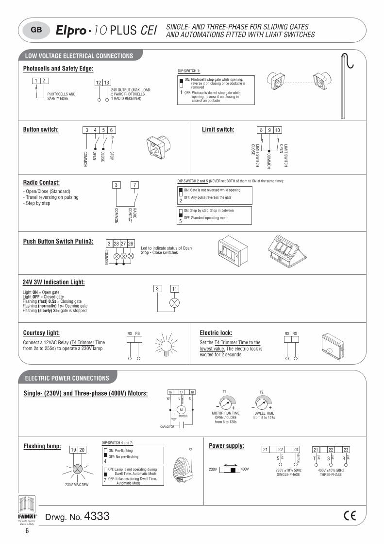
Courtesy light: RS RS
Connect a 12VAC Relay (T4 Trimmer Timefrom 2s to 255s) to operate a 230V lamp
Electric lock: RS RS
Set the T4 Trimmer Time to thelowest value. The electric lock isexcited for 2 seconds
Button switch: 3 4 5 6
1
DIP-SWITCH 1:
ON: Photocells stop gate while opening, reverse it on closing once obstacle is removedOFF: Photocells do not stop gate while opening, reverse it on closing in case of an obstacle
1 2
PHOTOCELLS ANDSAFETY EDGE
12 1324V OUTPUT (MAX. LOAD:2 PAIRS PHOTOCELLS1 RADIO RECEIVER)
Limit switch: 108 9
Light ON = Open gateLight OFF = Closed gateFlashing (fast) 0.5s = Closing gateFlashing (normally) 1s= Opening gateFlashing (slowly) 2s= gate is stopped
24V 3W Indication Light:3 11
2627283
COMM
ON
Led to indicate status of OpenStop - Close switches
Radio Contact:
COMM
ON
RADIOCONTACT
73- Open/Close (Standard)- Travel reversing on pulsing- Step by step 2
ON: Gate is not reversed while opening
OFF: Any pulse reverses the gate
5
ON: Step by step. Stop in between
OFF: Standard operating mode
DIP-SWITCH 2 and 5 (NEVER set BOTH of them to ON at the same time):
Photocells and Safety Edge:
STOP
COMM
ON
OPEN
CLOSE
COMM
ON
LIMIT SW
ITCHCLOSE
LIMIT SW
ITCHOPEN
Push Button Switch Pulin3:
230V 400V
CAPACITOR
1816 17
COMM
ON
M
MOTOR
UW V
230V ±10% 50HzSINGLE-PHASE
21 22
NEUTRAL
S
LIVE
2322 21 22
T RS
LIVE
2322
400V ±10% 50HzTHREE-PHASE
LIVE
LIVE
Flashing lamp:
4
ON: Pre-flashing
OFF: No pre-flashing
19 20
230V MAX 25W7
ON: Lamp is not operating during Dwell Time. Automatic Mode.OFF: It flashes during Dwell Time. Automatic Mode.
DIP-SWITCH 4 and 7: Power supply:
- +
T1
MOTOR RUN TIMEOPEN / CLOSEfrom 5 to 128s
T2
- +DWELL TIME
from 5 to 128s
Single- (230V) and Three-phase (400V) Motors:
LOW VOLTAGE ELECTRICAL CONNECTIONS
®
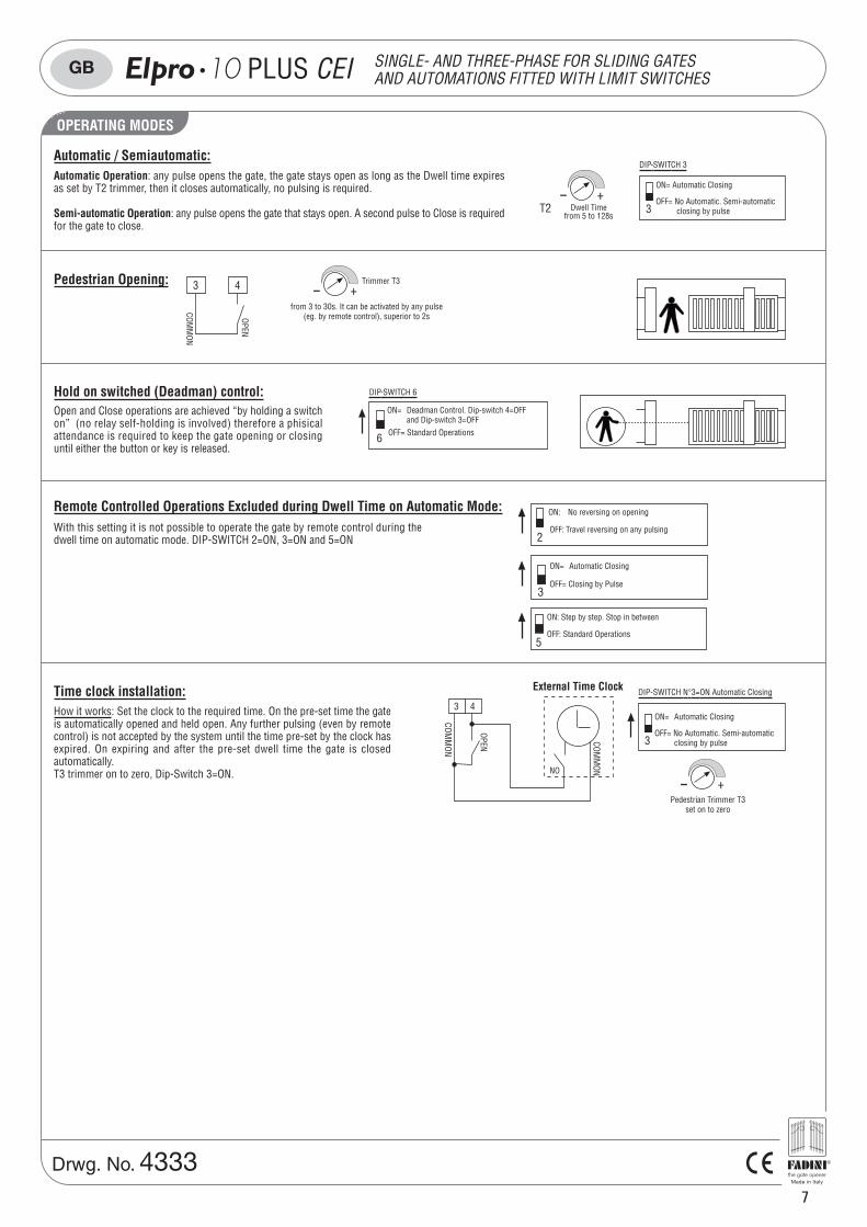
OPERATING MODES
7
Drwg. No. 4333
SINGLE- AND THREE-PHASE FOR SLIDING GATESAND AUTOMATIONS FITTED WITH LIMIT SWITCHES10 PLUS CEIGB
Remote Controlled Operations Excluded during Dwell Time on Automatic Mode:
3
5
With this setting it is not possible to operate the gate by remote control during thedwell time on automatic mode. DIP-SWITCH 2=ON, 3=ON and 5=ON 2
Hold on switched (Deadman) control:
Pedestrian Opening: Trimmer T3- +
from 3 to 30s. It can be activated by any pulse(eg. by remote control), superior to 2s
Automatic / Semiautomatic:Automatic Operation: any pulse opens the gate, the gate stays open as long as the Dwell time expiresas set by T2 trimmer, then it closes automatically, no pulsing is required.
Semi-automatic Operation: any pulse opens the gate that stays open. A second pulse to Close is requiredfor the gate to close.
Open and Close operations are achieved “by holding a switchon” (no relay self-holding is involved) therefore a phisicalattendance is required to keep the gate opening or closinguntil either the button or key is released.
DIP-SWITCH 6
6
ON= Deadman Control. Dip-switch 4=OFFand Dip-switch 3=OFF
OFF= Standard Operations
How it works: Set the clock to the required time. On the pre-set time the gateis automatically opened and held open. Any further pulsing (even by remotecontrol) is not accepted by the system until the time pre-set by the clock hasexpired. On expiring and after the pre-set dwell time the gate is closedautomatically.T3 trimmer on to zero, Dip-Switch 3=ON.
DIP-SWITCH N°3=ON Automatic Closing
3
ON= Automatic Closing
OFF= No Automatic. Semi-automaticclosing by pulse
- +Pedestrian Trimmer T3
set on to zero
3
DIP-SWITCH 3
ON= Automatic Closing
OFF= No Automatic. Semi-automatic closing by pulseDwell Time
from 5 to 128s
- +T2
COMM
ON
OPEN
43
Time clock installation:43
COMM
ON
COMM
ON
OPEN
NO
External Time Clock
ON= Automatic Closing
OFF= Closing by Pulse
ON: Step by step. Stop in between
OFF: Standard Operations
ON: No reversing on opening
OFF: Travel reversing on any pulsing
®
8
Drwg. No. 4086
12 PLUSGB
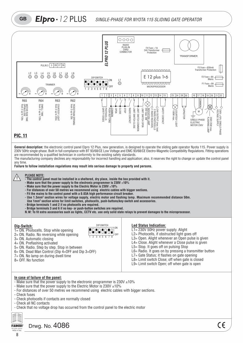
In case of failure of the panel:- Make sure that the power supply to the electronic programmer is 230V ±10%- Make sure that the power supply to the Electric Motor is 230V ±10%- For distances of over 50 metres we recommend using electric cables with bigger sections.- Check fuses- Check photocells if contacts are normally closed- Check all NC contacts- Check that no voltage drop has occurred from the control panel to the electric motor
General description: the electronic control panel Elpro 12 Plus, new generation, is designed to operate the sliding gate operator Nyota 115. Power supply is230V 50Hz single-phase. Built in full compliance with BT 93/68/CE Low Voltage and EMC 93/68/CE Electro-Magnetic Compatibility Regulations. Fitting operationsare recommended by a qualified technician in conformity to the existing safety standards.The manufacturing company declines any responsability for incorrect handling and application; also, it reserves the right to change or update the control panelany time.Failure to follow installation regulations may result into serious damage to property and persons.
PLEASE NOTE:- The control panel must be installed in a sheltered, dry place, inside the box provided with it.- Make sure that the power supply to the electronic programmer is 230V ±10%- Make sure that the power supply to the Electric Motor is 230V ±10%- For distances of over 50 metres we recommend using electric cables with bigger sections.- Fit the mains to the control panel with a 0.03A high performance circuit breaker.- Use 1.5mm2 section wires for voltage supply, electric motor and flashing lamp. Maximum recommended distance 50m.
Use 1mm2 section wires for limit switches, photocells, push-buttons/key-switch and accessories.- Bridge terminals 1 and 2 if no photocells are required.- Bridge terminals 3 and 6 if no key- or push-button switches are required.N.W: To fit extra accessories such as lights, CCTV etc. use only solid state relays to prevent damages to the microprocessor.
DIP-SWITCH
1 4 5 6 7 82
ON
OFF3
Dip-Switch:1= ON. Photocells. Stop while opening2= ON. Radio. No reversing while opening3= ON. Automatic closing4= ON. Preflashing activated5= ON. Radio. Step by step. Stop in between6= ON. Dead Man Control (Dip 4=OFF and Dip 3=OFF)7= ON. No lamp on during dwell time8= OFF. No function
Led Status Indication:L1= 230V 50Hz power supply. AlightL2= Photocells, if obstructed light goes offL3= Open. Alight whenever an Open pulse is givenL4= Close. Alight whenever a Close pulse is givenL5= Stop. It goes off on pulsing StopL6= Radio. It goes on by pressing a transmitter buttonL7= Gate Status; it flashes on gate openingL8= Limit switch Close; off when gate is closedL9= Limit switch Open; off when gate is open
PULIN 3 2627283
F4 Fuse = 1A24V Transformer
Protection
RADIOPLUG-IN
CARDCONNECTOR
PEDESTRIAN OPENINGfrom
3 up to 30s
ELPR
O 12
PLU
S
1816 17
COMM
ON
M
SINGLE-PHASEELECTRICMOTOR 230V
24V OUTPUT (max. load:
2 PAIRS PHOTOCELLS1 RADIO RECEIVER)
INDICATION LAMP
24V max. 3W
STOP
COMM
ONPUSH BUTTONS
OPEN
CLOSE
PHOTOCELLSSAFETY EDGES
RADIO CONTACT
LIMIT SW
ITCH CLOSE
LIMIT SW
ITCH OPEN
LIMIT SW
ITCH COMM
ON
COURTESY LIGHTfrom
2 up to 255s
DWELL TIM
Efrom
2 up to 128s
MOTOR RUN TIM
EOPEN/CLOSEfrom
2 up to 128s
F3 Fuse = 630mATransformer Protection
F2 Fuse = 8AMains
F1 Fuse = 8AMains
19 20 21 222923 24 301 2 3 4 5 6 7 8 9 10 11 12 13 14 15
SAFETY CONTACT
COURTESY LIGHT100W
max.
CAPACITOR 230V 25W m
ax.FLASHING LAM
P
230V ±10% SINGLE-PHASE
VOLTAGE SUPPLY
TRIMMER
DIP-SWITCHON
OFF1 4 5 6 7 82 3
L2 L3 L4 L5 L9L8L6 L7
L1
- + - + - + - +
R65 R64 R63 R62
MICROPROCESSOR
E 12 plus 1 6
TRANSFORMER
SINGLE-PHASE FOR NYOTA 115 SLIDING GATE OPERATOR
PIC. 11
®
ELECTRICAL POWER CONNECTIONS
9
Drwg. No. 4086
GB
Flashing lamp:19 20
230V MAX 25W
4
ON: Pre-flashing
OFF: No pre-flashing
7
ON: Lamp is not operating during Dwell time. Automatic mode.
OFF: It flashes during Dwell Time. Automatic Mode.
DIP-SWITCH 4 and 7:
1 2
Button switch:3 4 5 6
STOP
COMM
ON
OPEN
CLOSE
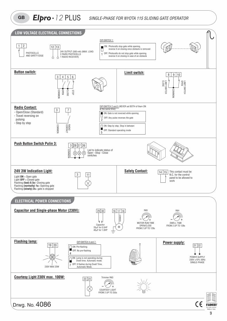
12 13
1
DIP-SWITCH 1:
ON: Photocells stop gate while opening,reverse it on closing once obstacle is removed
OFF: Photocells do not stop gate while opening,reverse it on closing in case of an obstacle
PHOTOCELLSAND SAFETY EDGE
24V OUTPUT (500 mA) (MAX. LOAD:2 PAIRS PHOTOCELLS1 RADIO RECEIVER)
Limit switch:
LIMIT SW
ITCHCLOSE
COMM
ON
108 9
LIMIT SW
ITCHOPEN
Light ON = Open gateLight OFF = Closed gateFlashing (fast) 0.5s= Closing gateFlashing (normally) 1s= Opening gateFlashing (slowly) 2s= gate is stopped
24V 3W Indication Light:3 11
Push Button Switch Pulin 3: 2627283
COMM
ON
Led to indicate status ofOpen - Stop - Closeswitches
Safety Contact:
Radio Contact:
COMM
ON
CONTACTRADIO
73- Open/Close (Standard)- Travel reversing on pulsing- Step by step
2
ON: Gate is not reversed while opening
OFF: Any pulse reverses the gate
5
ON: Step by step. Stop in between
OFF: Standard operating mode
DIP-SWITCH 2 and 5 (NEVER set BOTH of them ONat the same time):
This contact must beN.C. for the controlpanel to be allowed towork
14 15
Power supply:
POWER SUPPLY230V ±10% 50HzSINGLE-PHASE
21 22
Capacitor and Single-phase Motor (230V):
- +
R65
MOTOR RUN TIMEOPEN/CLOSE
FROM 2 UP TO 128s
R64
- +DWELL TIME
FROM 2 UP TO 128s
29 30 1816 17
COMM
ON
MCapacitor
20μF for 0.5HP40μF for 1.0HP
Courtesy Light 230V max. 100W: 23 24 Trimmer R63
- +COURTESY LIGHT
FROM 2 UP TO 255s
12 PLUS SINGLE-PHASE FOR NYOTA 115 SLIDING GATE OPERATOR
Photocells and Safety Edge:LOW VOLTAGE ELECTRICAL CONNECTIONS
®
OPERATING MODES
10
Drwg. No. 4086
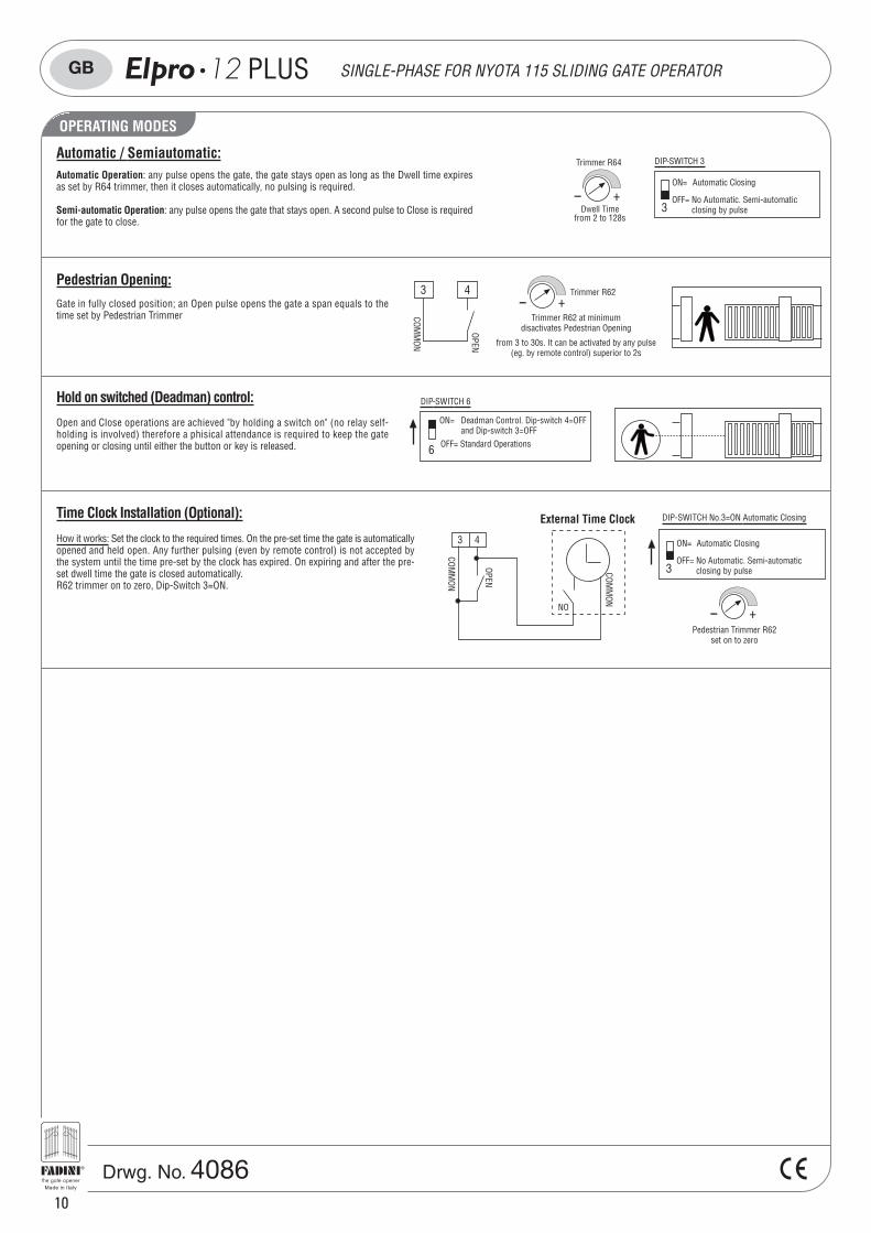
How it works: Set the clock to the required times. On the pre-set time the gate is automaticallyopened and held open. Any further pulsing (even by remote control) is not accepted bythe system until the time pre-set by the clock has expired. On expiring and after the pre-set dwell time the gate is closed automatically.R62 trimmer on to zero, Dip-Switch 3=ON.
DIP-SWITCH No.3=ON Automatic Closing
3
ON= Automatic Closing
OFF= No Automatic. Semi-automatic closing by pulse
- +Pedestrian Trimmer R62
set on to zero
Hold on switched (Deadman) control:
Pedestrian Opening:Trimmer R62
- +Trimmer R62 at minimum
disactivates Pedestrian Opening
from 3 to 30s. It can be activated by any pulse(eg. by remote control) superior to 2s
Automatic / Semiautomatic:Automatic Operation: any pulse opens the gate, the gate stays open as long as the Dwell time expiresas set by R64 trimmer, then it closes automatically, no pulsing is required.
Semi-automatic Operation: any pulse opens the gate that stays open. A second pulse to Close is requiredfor the gate to close.
Open and Close operations are achieved "by holding a switch on" (no relay self-holding is involved) therefore a phisical attendance is required to keep the gateopening or closing until either the button or key is released.
DIP-SWITCH 6
6
ON= Deadman Control. Dip-switch 4=OFF and Dip-switch 3=OFFOFF= Standard Operations
3
DIP-SWITCH 3
ON= Automatic Closing
OFF= No Automatic. Semi-automatic closing by pulseDwell Time
from 2 to 128s
- +
Trimmer R64
COMM
ON
OPEN
43Gate in fully closed position; an Open pulse opens the gate a span equals to thetime set by Pedestrian Trimmer
Time Clock Installation (Optional):
43
COMM
ON
COMM
ON
OPEN
NO
External Time Clock
GB 12 PLUS SINGLE-PHASE FOR NYOTA 115 SLIDING GATE OPERATOR
®
11
Drwg. No. 4198
GB 14 PLUS
!
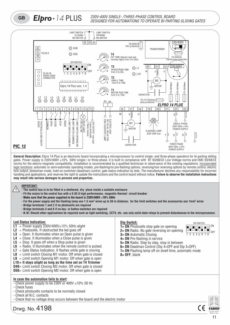
In case the automation fails to start:- Check power supply to be 230V or 400V ±10% 50 Hz- Check fuses- Check photocells contacts to be normally closed- Check all N.C. contacts- Check that no voltage drop occurs between the board and the electric motor
General Description: Elpro 14 Plus is an electronic board incorporating a microprocessor to control single- and three-phase operators for bi-parting slidinggates. Power supply is 230V/400V ±10% 50Hz single-/ or three-phase. it is built in compliance with BT 93/68/CE Low Voltage norms and EMC 93/68/CEnorms for the electro-magnetic compatibility. Installation is recommended by a qualified technician in observance of the existing regulations. Incorporatedlogic functions: automatic or semi-automatic operating modes, pre-flashing/no pre-flashing options, reversing/non reversing options by remote control, electriclock output, pedestrian mode, hold-on-switched (deadman) control, gate status indication by leds. The manufacturer declines any responsability for incorrecthandling and applications, and reserves the right to update the instructions and the control board without notice. Failure to observe the installation instructionsmay result into serious damages to persons and properties.
IMPORTANT:- The control box is to be fitted in a sheltered, dry place inside a suitable enclosure- Fit the mains to the control box with a 0.03 A high performance, magnetic-thermal circuit breaker- Make sure that the power supplied to the board is 230V/400V ±10% 50Hz- For the power supply and the flashing lamp use 1.5 mm2 wires up to 50 m distance; for the limit switches and the accessories use 1mm2 wires- Bridge terminals 1 and 2 if no photocells are required- Bridge terminals 3 and 6 if no key- or button-switches are required- N.W: Should other applications be required such as light switching, CCTV, etc. use only solid state relays to prevent disturbances to the microprocessor.
DIP-SWITCH
1 4 5 6 7 82
ON
OFF3
Dip-Switch:1= ON Photocells stop gate on opening2= ON Radio. No gate reversing on opening3= ON Automatic Closing4= ON Pre-flashing in service5= ON Radio. Step by step, stop in between6= ON Deadman Control (Dip 4=OFF and Dip 3=OFF)7= ON Flashing lamp off on dwell time, automatic mode8= OFF, blank
Led Status Indication:L1 = Power supply 230V/400V±10% 50Hz alightL2 = Photocells. If obstructed the led goes offL3 = Open. It illuminates when an Open pulse is givenL4 = Close. It illuminates when a Close pulse is givenL5 = Stop. It goes off when a Stop pulse is givenL6 = Radio. It illuminates when the remote control is pulsed.L7 = Gate Status Indication. It flashes while gate is movingL8 = Limit switch Closing M1 motor. Off when gate is closedL9 = Limit switch Opening M1 motor. Off when gate is openL10 = It stays alight as long as the time set on T4 TrimmerD49= Limit switch Closing M2 motor. Off when gate is closedD50= Limit switch Opening M2 motor. Off when gate is open
24V OUTPUT max load:
2 pairs photocells1 Radio receiver
PULIN 3
2627
283
DIP-SWITCHON
OFF1 4 5 6 7 82 3
L2 L3 L4 L5 L6L7L8 L9
PILOT LIGHT24V m
ax 3W
1 74 10 11 12 13 19 202 853 96
STOP
COMM
ON
OPEN
CLOSE
FLASHING LAMP230V 25W max
230/400V
L1
L10
F5=1A Flashinglamp protection
F4=630mAtransformer protection
F6=630mA24V protection
PLUG-INRADIO CARDCONNECTOR
TRANSFORMER
MOTOR RUN TIMEfrom 5 to 128s
DWELL TIME from 5 to 128s
PEDESTRIAN TIMEfrom 3 to 30s
- +
- +
- +
- +EXT TIME (Electric lock andcourtesy light) from 2 to 255s
T4
T3
T2
T1
PHOTOCELLS AND SAFETYEDGES
RADIO
LIMIT SW
ITCH CLOSING M1
LIMIT SW
ITCH OPENING M1
LIMIT SW
ITCH COMM
ON
ELPRO 14 PLUS21 22
T
NEUTRAL
S
LIVE
2322
ELECTRIC LOCKOR 12V AC RELAY FOR230V COURTESY LAM
P
RS RS
1816 17
COMM
ON
M1
MOTOR
UW V
SINGLE-PHASE230V 50Hz ±10%POWER SUPPLY
THREE-PHASE400V 50Hz ±10%POWER SUPPLY
S
LIVE R
NEUTRAL
35
LIMIT SWITCHCLOSING
M2 MOTOR
LIMIT SWITCHOPENINGM2 MOTOR
34 33
W
3230 31
COMM
ON
M2
MOTOR
UV
D49
D50
CAPACITOR
CAPACITOR
230/400V
Elpro 14 Plus vers. 1.4
F2=1
0A M
ains
F3=1
0A M
ains
F1=1
0A M
ains
230V-400V SINGLE- /THREE-PHASE CONTROL BOARDDESIGNED FOR AUTOMATIONS TO OPERATE BI-PARTING SLIDING GATES
PIC. 12
LIVE
LIVE
®
OPERATING MODESLOW VOLTAGE ELECTRICAL CONNECTIONS 11 12 131 74 102 853 96
12
Drwg. No. 4198
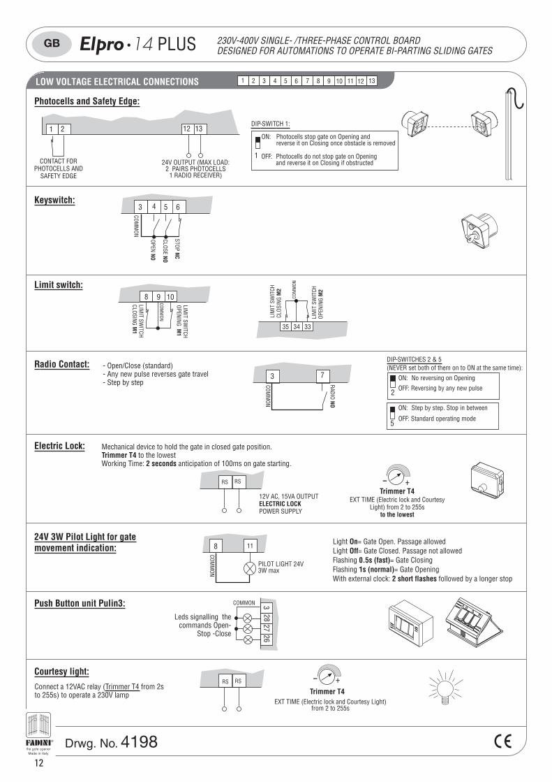
Radio Contact: - Open/Close (standard)- Any new pulse reverses gate travel- Step by step
Keyswitch:3 4 5 6
STOP NC
COMM
ON
OPEN NO
CLOSE NO
73
COMM
ON
RADIO NO
12V AC, 15VA OUTPUTELECTRIC LOCKPOWER SUPPLY
Electric Lock: Mechanical device to hold the gate in closed gate position.Trimmer T4 to the lowestWorking Time: 2 seconds anticipation of 100ms on gate starting.
11
PILOT LIGHT 24V3W max
8
COMM
ON
24V 3W Pilot Light for gatemovement indication:
Light On= Gate Open. Passage allowedLight Off= Gate Closed. Passage not allowedFlashing 0.5s (fast)= Gate ClosingFlashing 1s (normal)= Gate OpeningWith external clock: 2 short flashes followed by a longer stop
1 2
Photocells and Safety Edge:
12 13
1
DIP-SWITCH 1:
ON: Photocells stop gate on Opening andreverse it on Closing once obstacle is removed
OFF: Photocells do not stop gate on Openingand reverse it on Closing if obstructedCONTACT FOR
PHOTOCELLS ANDSAFETY EDGE
24V OUTPUT (MAX LOAD:2 PAIRS PHOTOCELLS
1 RADIO RECEIVER)
Limit switch:
LIMIT SW
ITCHCLOSING M
1
COMM
ON
108 9
LIMIT SW
ITCHOPENING M
1
Push Button unit Pulin3:Leds signalling the
commands Open-Stop -Close
Courtesy light:
Connect a 12VAC relay (Trimmer T4 from 2sto 255s) to operate a 230V lamp
RS RS
2
ON: No reversing on Opening
OFF: Reversing by any new pulse
5
ON: Step by step. Stop in between
OFF: Standard operating mode
DIP-SWITCHES 2 & 5(NEVER set both of them on to ON at the same time):
35 34 33
COM
MON
LIM
IT S
WIT
CHCL
OSIN
G M
2
LIM
IT S
WIT
CHOP
ENIN
G M
2
- +
2627
283COMMON
RS RS - +
EXT TIME (Electric lock and Courtesy Light)from 2 to 255s
Trimmer T4
Trimmer T4EXT TIME (Electric lock and Courtesy
Light) from 2 to 255sto the lowest
GB 14 PLUS 230V-400V SINGLE- /THREE-PHASE CONTROL BOARDDESIGNED FOR AUTOMATIONS TO OPERATE BI-PARTING SLIDING GATES
®
FUNCTIONS
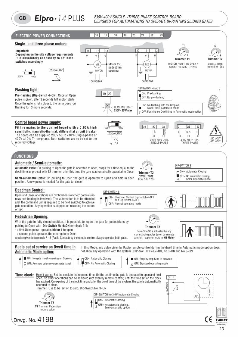
211816 17 19 22 2320ELECTRIC POWER CONNECTIONS
Trimmer T3
- +
From 3 to 30 s activated by anycommanding pulse (even by remotecontrol), superior to 2s to M1 Motor
5
ON: Step by step Stop in between
OFF: Standard operating mode
In this Mode, any pulse given by Radio remote control during the dwell time in Automatic mode option doesnot allow any operation with the system . DIP-SWITCH No.2=ON, No.3=ON and No.5=ON
43
COMM
ON
COMM
ON
OPEN
NO
T3 Trimmer. Pedestrianto zero value
Automatic cycle: On pulsing to Open the gate is operated to open, stops for a time equal to thedwell time as pre-set with T2 trimmer, after this time the gate is automatically operated to Close.
Semi-automatic Cycle: On pulsing to Open the gate is operated to Open and held in openposition. A new pulse is needed for the gate to close.
Radio out of service on Dwell time inAutomatic Mode option:
3
ON= Automatic Closing
OFF= No Automatic Closing
Deadman Control: DIP-SWITCH 6
6
ON= Deadman Control Dip-switch 4=OFFand Dip-switch 3=OFF
OFF= Normal operating mode
Time clock:
DIP-SWITCH No.3=ON Automatic Closing
3
ON= Automatic Closing
OFF= No automatic closing. Semi-automatic option
- +
2
ON: No gate travel reversing on Opening
OFF: Any new pulse reverses gate travel
4
ON: Pre-flashingOFF: No pre-flashing
7
ON: No flashing with the lamp onDwell time. Automatic mode
OFF: Flashing on Dwell time in Automatic mode option
DIP-SWITCH 4 and 7:
230V 400V
230V 50Hz ±10%SINGLE-PHASE
21 22
NEUTRAL
S
LIVE
2322
230/400V
Single- and three-phase motors:
Control board power supply:
Flashing light:
FADINIl'apricancello
19 20
FLASHING LIGHT230V - 25W max
Fi t the mains to the cont ro l board wi th a 0.03A h ighsensitivity, magnetic-thermal, differential circuit breakerThe board can be supplied 230V 50Hz ±10% Single-phase or400V ±10% Three-phase. Both switches are to be set to therequired voltage.
Automatic / Semi-automatic:
Pedestrian Opening:With the gate in fully closed position, it is possible to open the gate for pedestrians bypulsing to Open with Dip-Switch No.6=ON terminals 3-4:- a first Open pulse operates Motor 1 to open- a second pulse operates the other gate to OpenA pulse given to terminals 7 - 8 (Radio Contact) by the remote control always operates both gates.
230 VOLT400 VOLT
Pre-flashing (Dip-Switch 4=ON): Once an Openpulse is given, after 3 seconds M1 motor startsOnce the gate is fully closed, the lamp goes onflashing for 3 more seconds.
21 22
T RS
LIVE
2322
400V 50Hz ±10%THREE-PHASE
DWELL TIME from 5 to 128s
- +
3
DIP-SWITCH 3
ON= Automatic Closing
OFF= No automatic closingSemi-automatic mode
Trimmer T2
MOTOR RUN TIME OPEN /CLOSE FROM 5 TO 128s
- +
T1
Trimmer T1
T2
- +Trimmer T2DWELL TIME
from 5 to 128s
CAPACITOR
1816 17
COMM
ON
M1
MOTOR
UW V
COMM
ON
3230 31
M2
MOTOR
UW V
CAPACITOR
Motor forpedestrianopening
Trimmer T3
Important:Depending on the site voltage requirementsi t is absolutely necessary to set bothswitches accordingly
230V 400V
230/400V
How it works: Set the clock to the required time. On the set time the gate is operated to open and heldopen. No other operations can be achieved (not even by remote control) until the time set on the clockhas expired. On expiring of the clock time and after the dwell time of the system, the gate is automaticallyoperated to close.Trimmer T3 is to be set on to zero, Dip-Switch No. 3=ON
Open and Close operations are by "hold on switched" control (norelay self-holding is involved). The automation is to be attendedand the command unit is required to be held switched to achievegate operation. Any operation is stopped on releasing the buttonor key.
13
Drwg. No. 4198
GB 14 PLUS 230V-400V SINGLE- /THREE-PHASE CONTROL BOARDDESIGNED FOR AUTOMATIONS TO OPERATE BI-PARTING SLIDING GATES
®
14
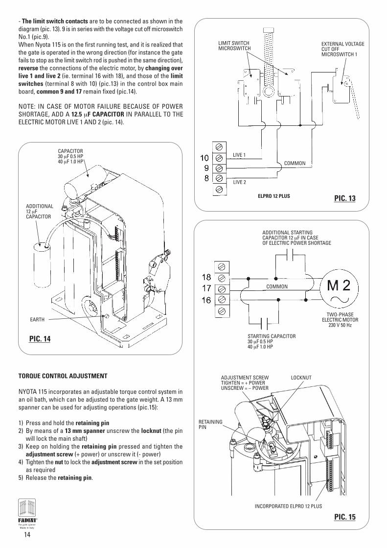
- The limit switch contacts are to be connected as shown in thediagram (pic. 13). 9 is in series with the voltage cut off microswitchNo.1 (pic.9).When Nyota 115 is on the first running test, and it is realized thatthe gate is operated in the wrong direction (for instance the gatefails to stop as the limit switch rod is pushed in the same direction),reverse the connections of the electric motor, by changing overlive 1 and live 2 (ie. terminal 16 with 18), and those of the limitswitches (terminal 8 with 10) (pic.13) in the control box mainboard, common 9 and 17 remain fixed (pic.14).
NOTE: IN CASE OF MOTOR FAILURE BECAUSE OF POWERSHORTAGE, ADD A 12.5 μF CAPACITOR IN PARALLEL TO THEELECTRIC MOTOR LIVE 1 AND 2 (pic. 14).
TORQUE CONTROL ADJUSTMENT
NYOTA 115 incorporates an adjustable torque control system inan oil bath, which can be adjusted to the gate weight. A 13 mmspanner can be used for adjusting operations (pic.15):
1) Press and hold the retaining pin2) By means of a 13 mm spanner unscrew the locknut (the pin
will lock the main shaft)3) Keep on holding the retaining pin pressed and tighten the
adjustment screw (+ power) or unscrew it (- power)4) Tighten the nut to lock the adjustment screw in the set position
as required5) Release the retaining pin.
EXTERNAL VOLTAGECUT OFFMICROSWITCH 1
LIMIT SWITCHMICROSWITCH
ELPRO 12 PLUS
LIVE 1
LIVE 2
COMMON
PIC. 13
CAPACITOR30 μF 0.5 HP40 μF 1.0 HP
ADDITIONAL12 μFCAPACITOR
EARTH
PIC. 14
PIC. 15
ADJUSTMENT SCREWTIGHTEN = + POWERUNSCREW = – POWER
LOCKNUT
RETAININGPIN
INCORPORATED ELPRO 12 PLUS
TWO-PHASEELECTRIC MOTOR
230 V 50 Hz
STARTING CAPACITOR30 μF 0.5 HP40 μF 1.0 HP
ADDITIONAL STARTINGCAPACITOR 12 μF IN CASEOF ELECTRIC POWER SHORTAGE
COMMON
®
15
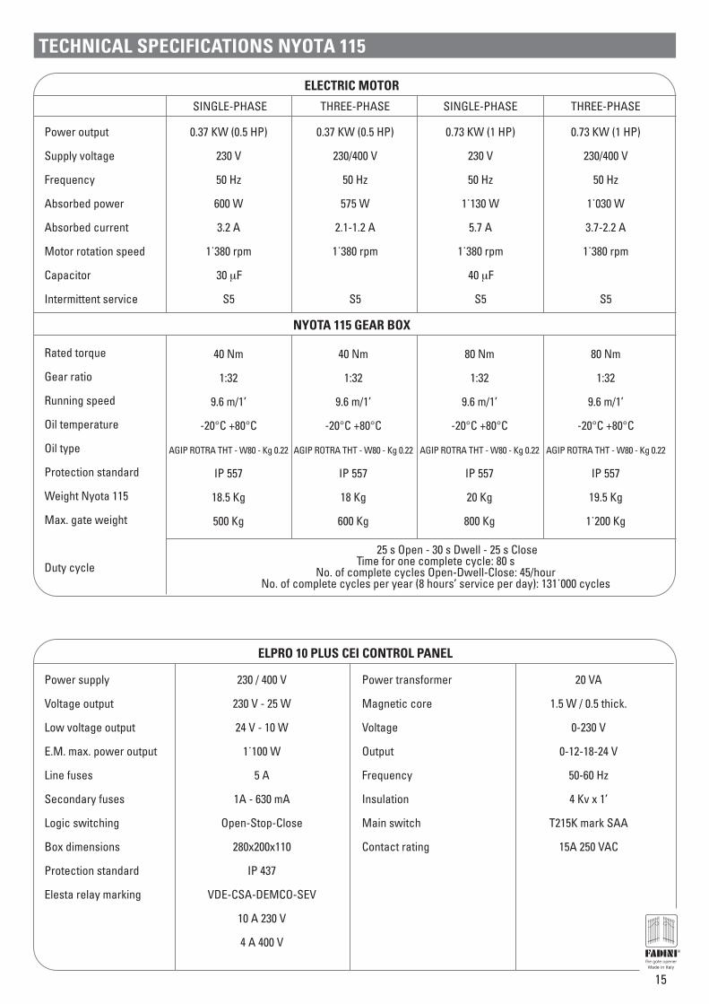
TECHNICAL SPECIFICATIONS NYOTA 115
Power output
Supply voltage
Frequency
Absorbed power
Absorbed current
Motor rotation speed
Capacitor
Intermittent service
ELECTRIC MOTOR
SINGLE-PHASE THREE-PHASE
0.37 KW (0.5 HP)
230 V
50 Hz
600 W
3.2 A
1˙380 rpm
30 μF
S5
0.37 KW (0.5 HP)
230/400 V
50 Hz
575 W
2.1-1.2 A
1˙380 rpm
S5
NYOTA 115 GEAR BOX
Rated torque
Gear ratio
Running speed
Oil temperature
Oil type
Protection standard
Weight Nyota 115
Max. gate weight
Duty cycle
40 Nm
1:32
9.6 m/1’
-20°C +80°C
AGIP ROTRA THT - W80 - Kg 0.22
IP 557
18.5 Kg
500 Kg
25 s Open - 30 s Dwell - 25 s CloseTime for one complete cycle: 80 s
No. of complete cycles Open-Dwell-Close: 45/hourNo. of complete cycles per year (8 hours’ service per day): 131˙000 cycles
Power supply
Voltage output
Low voltage output
E.M. max. power output
Line fuses
Secondary fuses
Logic switching
Box dimensions
Protection standard
Elesta relay marking
ELPRO 10 PLUS CEI CONTROL PANEL
Power transformer
Magnetic core
Voltage
Output
Frequency
Insulation
Main switch
Contact rating
230 / 400 V
230 V - 25 W
24 V - 10 W
1˙100 W
5 A
1A - 630 mA
Open-Stop-Close
280x200x110
IP 437
VDE-CSA-DEMCO-SEV
10 A 230 V
4 A 400 V
20 VA
1.5 W / 0.5 thick.
0-230 V
0-12-18-24 V
50-60 Hz
4 Kv x 1’
T215K mark SAA
15A 250 VAC
SINGLE-PHASE THREE-PHASE
0.73 KW (1 HP)
230 V
50 Hz
1˙130 W
5.7 A
1˙380 rpm
40 μF
S5
0.73 KW (1 HP)
230/400 V
50 Hz
1˙030 W
3.7-2.2 A
1˙380 rpm
S5
40 Nm
1:32
9.6 m/1’
-20°C +80°C
AGIP ROTRA THT - W80 - Kg 0.22
IP 557
18 Kg
600 Kg
80 Nm
1:32
9.6 m/1’
-20°C +80°C
AGIP ROTRA THT - W80 - Kg 0.22
IP 557
20 Kg
800 Kg
80 Nm
1:32
9.6 m/1’
-20°C +80°C
AGIP ROTRA THT - W80 - Kg 0.22
IP 557
19.5 Kg
1˙200 Kg
®
16
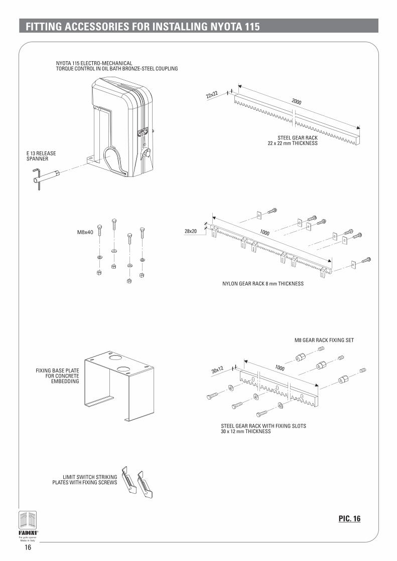
FITTING ACCESSORIES FOR INSTALLING NYOTA 115
LIMIT SWITCH STRIKINGPLATES WITH FIXING SCREWS
22x222000
30x12 1000
STEEL GEAR RACK WITH FIXING SLOTS30 x 12 mm THICKNESS
M8x40
NYLON GEAR RACK 8 mm THICKNESS
100028x20
PIC. 16
M8 GEAR RACK FIXING SET
NYOTA 115 ELECTRO-MECHANICALTORQUE CONTROL IN OIL BATH BRONZE-STEEL COUPLING
STEEL GEAR RACK22 x 22 mm THICKNESS
FIXING BASE PLATEFOR CONCRETE
EMBEDDING
E 13 RELEASESPANNER
®
17
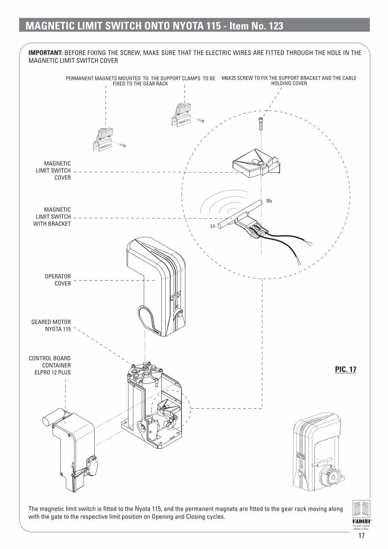
MAGNETIC LIMIT SWITCH ONTO NYOTA 115 - Item No. 123
PERMANENT MAGNETS MOUNTED TO THE SUPPORT CLAMPS TO BEFIXED TO THE GEAR RACK
Rh
Lh
M6X25 SCREW TO FIX THE SUPPORT BRACKET AND THE CABLEHOLDING COVER
MAGNETICLIMIT SWITCH
COVER
MAGNETICLIMIT SWITCH
WITH BRACKET
The magnetic limit switch is fitted to the Nyota 115, and the permanent magnets are fitted to the gear rack moving alongwith the gate to the respective limit position on Opening and Closing cycles.
OPERATORCOVER
CONTROL BOARDCONTAINER
ELPRO 12 PLUS
GEARED MOTORNYOTA 115
IMPORTANT: BEFORE FIXING THE SCREW, MAKE SURE THAT THE ELECTRIC WIRES ARE FITTED THROUGH THE HOLE IN THEMAGNETIC LIMIT SWITCH COVER
PIC. 17
®
18
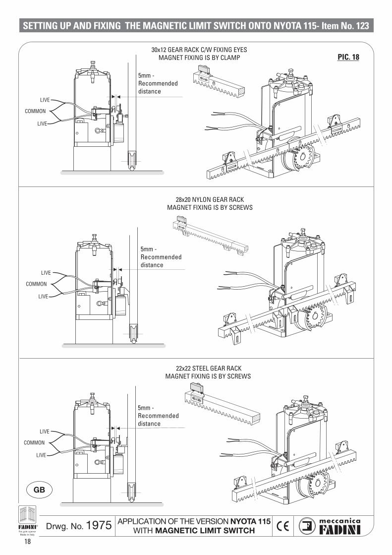
SETTING UP AND FIXING THE MAGNETIC LIMIT SWITCH ONTO NYOTA 115- Item No. 123
5mm -Recommendeddistance
30x12 GEAR RACK C/W FIXING EYESMAGNET FIXING IS BY CLAMP
LIVE
LIVE
COMMON
5mm -Recommendeddistance
LIVE
LIVE
COMMON
28x20 NYLON GEAR RACKMAGNET FIXING IS BY SCREWS
5mm -Recommendeddistance
LIVE
LIVE
COMMON
22x22 STEEL GEAR RACKMAGNET FIXING IS BY SCREWS
GB
Drwg. No. 1975 APPLICATION OF THE VERSION NYOTA 115WITH MAGNETIC LIMIT SWITCH
PIC. 18
®
19
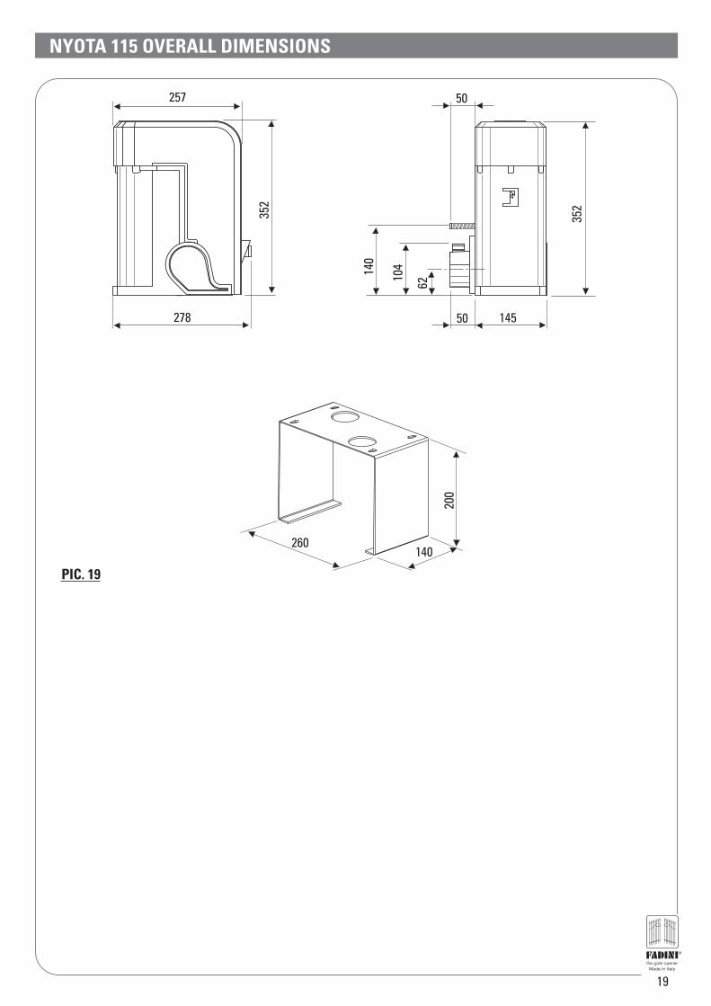
PIC. 19
NYOTA 115 OVERALL DIMENSIONS
352
14550
50
6210414
0
257
278
352
260
200
140
®

04-2
007
The manufacturers reserve the right to change the products without any previous notice
Distributor’s box
AUTOMATIC GATE MANUFACTURERS
Via Mantova, 177/A - 37053 Cerea (Verona) ItalyTel. 0442 330422 r.a. - Fax 0442 331054e-mail: [email protected] - www.fadini.net
s.n.c.
®
NYOTA 115ELECTRO-MECHANICAL SLIDING GATE OPERATOR
IMPORTANT WARNING NOTES- Before installing the equipment carry out a Risk Analysis and fit any required device in compliance with EN 12445 and
EN 12453 Safety Norms.- lt is recommended to keep to the instructions in this booklet - make sure that the motor specifications as printed on the
motor sticker conform to those of the mains.- Dispose properly of the packaging materials such as cardboard, nylon and polystyrene through specialized companies.- Should the operator be removed, do not cut the electrical cables, but properly remove them by loosening the pins in the
terminal board.- Switch off the mains switch before the cover of the motor terminal board is removed.- All the equipment must be properly earthed by the yellow/green cable marked with the specific symbol.- It is recommended to carefully read the regulations, advice and remarks in the book “Safety Norms”.
The growth of MECCANICA FADINI has always been based on the development of guaranteed products thanks to our “TOTALQUALITY CONTROL” system which ensures constant quality standards, updated knowledge of the European Standards andcompliance with their requirements, in view of an ever increasing process of improvement.
EUROPEAN MARK CERTIFYING CONFORMITYTO THE ESSENTIAL REQUIREMENTS OF THESTANDARDS 98/37/EC
• DECLARATION OF CONFORMITY• SAFETY NORMS• EN 12453, EN 12445 STANDARDS• CEI EN 60204-1 STANDARDS• WARRANTY CERTIFICATE ON THE CUSTOMER'S REQUEST
The “CE” mark certifies that the operator conforms to the essential requirements of the European Directive art. 10 EEC 73/23, in relationto the manufacturer’s declaration for the supplied items, in compliance with the body of the regulations ISO 9000-UNI EN 29000.Automation in conformity to EN 12453, EN 12445 safety standard.
CHECKING AND MAINTENANCE:To achieve an optimum performance and longer life of the equipment and in observance of the safety regulations, it is recommendedthat inspections and proper maintenance are made by qualified technicians to the whole installation ie. both the mechanical andelectronic parts, as well as wiring.- Mechanical parts: maintenance every 6 months approx.- Electronic apparatus and safety equipment: maintenance every month approx.