Embed Size (px)
Citation preview

LIEBABasic Electronics and Electricity Integrated Laboratory
Technical Teaching Equipment
Basic Electronics concepts M3. Semiconductors I. M4. Semiconductors II. M6. Oscillators. M7. Operational Amplifiers. M8. Filters. M9. Power Electronics. M60. Analog/Digital Converters. M61. Digital/Analog Converters. M99. Expansion Unit:
Modules included:M99-1. Analog Multiplexer module.M99-2. Analog Multiplier module.M99-3. Function Generator module.M99-4. AM Modulator module.M99-5. AM Demodulator module.
M99-6. Motors, Generators and Controls Unit.Digital Electronics
M10. Digital Systems & Converters. M11. Digital Electronics Fundamentals. M12. Basic Combinational Circuits. M13. Basic Sequential Circuits. M14. Optoelectronics. M41. Resistance Transducers.
Basic Electricity concepts M5. Power Supplies. M1. Direct Current (D.C.) Circuits. M2. Alternating Current (A.C.) Circuits. M16. Electric Networks. M17. Electromagnetism. M18. Three-phase Circuits.
Electronics Applications M49. Applications of Temperature and
Pressure. M44. Applications of Light. M45. Linear Position and Force. M46. Environmental Measurements. M15. Development Module. M48. Sounds Measurements.
Control RYC/B. Basic Teaching Unit for the Study of
Regulation and Control. M47. Rotational Speed & Position Control.
Available Modules:
The complete laboratory includes parts 1 to 5 and any part can be supplied individually or additionally. (Power supply + Module/s is the minimum supply).
Laboratory structure
(M61)
Modules2(Power supply needed)
CAI. Computer Aided Instruction Software System
EDAS/VIS. EDIBON Data Acquisition System/ Virtual Instrumentation System
3
4
5
LIEBA/CAL. Computer Aided Learning Software (Results Calculation and Analysis)
EBC-100
Power Supply 1
or
FA-CO
PC
New modules in designing process
TeachingTechnique
used
Page 1
EDAS/VIS-SOF. Data Acquisition and Virtual Instrumentation
Software
DAIB. Data Acquisition Interface Box
DAB. Data Acquisition Board
BB Data Acquisition Interface Box
TeachingTechnique
used
++
European Union Certificate(total safety)
ISO 9000: Quality Management(for Design, Manufacturing,
Commercialization and After-sales service)
Certificates ISO 14000 and ECO-Management and Audit Scheme
(environmental management)
Worlddidac Quality Charter Certificate and
Worlddidac Member
+INS/SOF. Instructor Softwaret tt
M../SOF. Student/Module
Software
(M3)
(M4)
(M6)
(M7)
(M8)
(M9)
(M60)
(M10)
(M11)( )
( )
Modules2(Power supply needed)
(M49)
TeachingTechnique
used
(M12)
(M13)
(M14)
(M1)
(M16)
(M18)
(M5)
(M2)
(M17)
(M49)
( )
( )
( )
( )
( )
( )
( )
(M18)
(M17)
(M16)))))
( )
(M1)
( )
(M12)
INTRODUCTION
GENERAL DESCRIPTION
We present a flexible and modular-based system for learning basic electronics, basic electricity and circuit theory. The advantage given by this learning and teaching system is that the student establishes his own rhythm, thus rendering unnecessary to keep pace with the rest of the class. Any desired configuration can be chosen (see next page), according to working mode, areas of study and number of working posts.Being a modular and open system, it is very economical and may be enlarged depending on required needs; all previously acquired systems are fully compatible and valid.
What are the parts included in the laboratory?:
Power supply: There are two choices for supplying the modules: FA-CO. Power Supply: Using this system training and practices can be done conventionally. This is the most common power supply used. EBC-100. Base Unit, with built-in power supply: This unit is self-complete, it includes hardware, power supply and the necessary connections for supplying power and allocating the available
modules.
Modules: They consist on modules which allow the student to do the exercises/practices corresponding to the target subject. On these modules the circuits to be designed are serigraphed. Real components are displayed to familiarize the student with them. There are
many points where measures can be taken (voltage, current intensity, resistance, etc.). Moreover, circuit and electronic components faults can be simulated too. Every Module has its own manuals, that gives the theoretical knowledge and explains everything the student needs to carry out the
exercise/practice. We provide eight manuals per module. Connectors and cables for completing the exercises and practices are included.
CAI. Computer Aided Instruction Software System: The best help in classroom for both teacher and students. It includes: - INSTRUCTOR SOFTWARE: INS/SOF. Classroom Management Software (Instructor Software). Only one software is needed per classroom. Helps creating databases, reports and statistical comparisons among many more features. - STUDENT SOFTWARE: M../SOF. Computer Aided Instruction Softwares (Student/Module Software). Each module has its own software. Gives the students the proper assistance on theoretical knowledge as well as in practice, presenting exercises and questions.
LIEBA/CAL. Computer Aided Learning Software (Results Calculation and Analysis): Windows based software, simple and easy to use. Thought for Results Calculation and Analysis, this software computes, displays and plots obtained data.
EDAS/VIS. EDIBON Data Acquisition System/Virtual Instrumentation System: EDIBON has developed this unique data acquisition interface, link between modules and PC, for an adequate visualization of the
results yielded by the modules. The components together (hardware + software) makes the computer work as virtual instruments: Oscilloscope, Functions Generator,
Spectrum Analyzer, Transient Analyzer, Multimeter, Logic Analyzer and Logic Generator, with all their features and applications. It includes: - Hardware: DAIB. Data Acquisition Interface Box + DAB. Data Acquisition Board. - Software: EDAS/VIS-SOF. Data Acquisition and Virtual Instrumentation Software.
Complete LIEBA LABORATORY includes: Minimum configuration: Power supply + Modules (Every module needs power supply).
Present technology requires necessary knowledge of ELECTRONICS and ELECTRICITY in most fields.
Avionics, Autotronics, Domotics, Agrotronics, Physics, Process Chemistry, Health Services, etc., already employ components or even whole systems based on Electronics and Electricity. Thus there is an increasing number of professionals in these and many other fields who need adequate knowledge and training.
Taken this into account, EDIBON has developed the Basic Electronics and Electricity Integrated Laboratory, capable of covering different levels of difficulty. It is based on a series of self-taught modules, each one referring to a specific area of Electricity and Electronics.
1
1 2 3 4 5
2
3
4
5
1 2
+ + + +
www.edibon.comPage 2
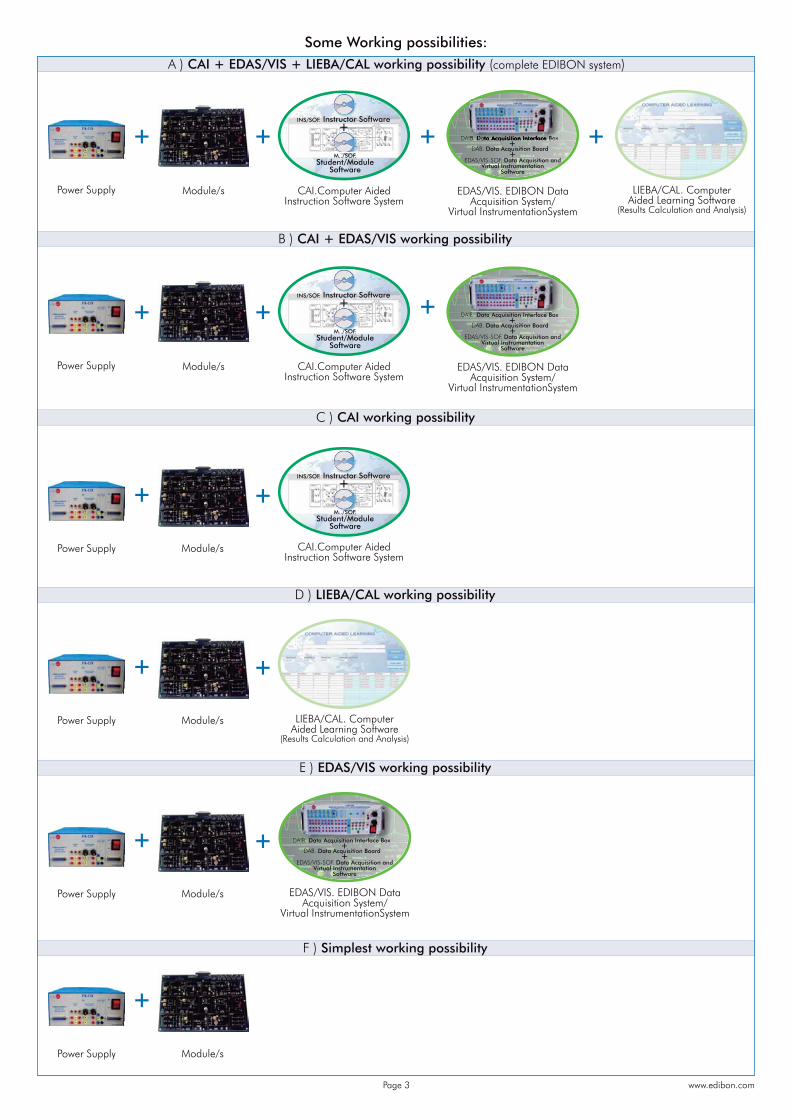
Some Working possibilities:A ) CAI + EDAS/VIS + LIEBA/CAL working possibility (complete EDIBON system)
B ) CAI + EDAS/VIS working possibility
F ) Simplest working possibility
E ) EDAS/VIS working possibility
CAI.Computer AidedInstruction Software System
EDAS/VIS. EDIBON Data Acquisition System/
Virtual InstrumentationSystem
Power Supply Module/s LIEBA/CAL. ComputerAided Learning Software
(Results Calculation and Analysis)
D ) LIEBA/CAL working possibility
EDAS/VIS. EDIBON Data Acquisition System/
Virtual InstrumentationSystem
C ) CAI working possibility
Power Supply Module/s
EDAS/VIS-SOF. Data Acquisition and Virtual Instrumentation
Software
DAIB. Data acquisition interface box
DAB. Data acquisition board
www.edibon.comPage 3
EDAS/VIS-SOF. Data Acquisition and Virtual Instrumentation
Software
DAIB. Data Acquisition Interface Box
DAB. Data Acquisition Board
BB Data Acquisition Interface Box
++
EDAS/S/VS/VVAS/VDAS/EDASE ISISS-SOFOFSOFSOFSSSS ..FFFFFF DDatDataDaDaDaDaDa AcqAcquiAAAcqAcquiAcquAcquiAcquAcquiAAcquAcquiiAAAcquAcqAcquiAcquiAAcquAAAcquiAcAAAcquiAcquiAcquiAcquiAcquiAAAAAc uuuiAcquiuAcquisissitiosi iitiositsitiositiositiositiositiositiitsitiositisitisititsitissisits ositi n aaanndn ndndnnddndn ndnddnn andn andn andddn andn ddddn ddddddn andddn VirtuVirtVVirtuVirirtuVi trturtuVirtuirturtuirtui tiirturtuurtutVirtuVirtui tirtuVi tiVirturttuVirttuui trturturtuututrtttuturrrtttuuuual Inal Inal l Il Ial Inal Inal al lal Inl Inall Inl InInnal Inl Inl Ial Inal Inl Ial Inll Il InInIl Il Inl Innna InInnnIInInnIIInnnn mstrummstrumsstruummstrummstrumstrumstrumstrumstrumstrumstrums mmmmmmmmmmeentaentatentaentatatententattatentaentatentatentatentatentatentatentatentatnntnttentaaattentateentatntaentententanentate iioion ion ion iioiiiioioioooioioio
SoftwSSoftwSoftwSoftwSoftwSoSoftwoftwooftwwwSooSoSooSooSofSoftwSoftwSoSo woftwSoftwSSSoSoftwSoftwSoftwoftwSSoSoSo wareareaaaaarearearearearrereearerearearearearereareeareaarereea
DDADADADADDDADDAADDADADDDDAAADADADADADDAADAADDDADAAADDADAADDA oxoxxxxxx
DDDDDDDDDDDDDDDAAAAAAAAAAAAAAAAA qqDDDDDDDDDDDDDDDDDDDAAAAAAAAAAAAAABABABBBBAAAAAAAAA ... DData DaDDatDaDatDatData DataaaDataattDatDatata atttaDaatData acaaaaacquiacqa ssitioiioiooooooiooooioioiionn nn bn boann bon bobbbn boannnn boan bbnnnnnnn boabboaonnn boabobn boab rdrddrddrdrddrdrdrdrddd
EDAS/VIS-SOF. Data Acquisition and Virtual Instrumentation
Software
DAIB. Data Acquisition Interface Box
DAB. Data Acquisition Board
DDDDDDDDDDDD
bbbbbbbboooooobboooboobbbbboooo
AAAAAAAAAAAAAAAAAAAAAAAAAAAAABDDDDDDDDDDDDDDDDDDDDDDAAAAAAAAAAData A i i i f ce BoxABBBBABABABABABABAABAAAAAAAAABAABBAAB DD tDataD tDDDataDatDataDataDataDDDataDatDatDataataDatDaDaDataDatDattDatataatDatttDatataDaaatDa acquiiaacquiaacquiiaaacquiaaaa itiititisitiositioiositiositiositioioooooiooooooo bbbbbon bobbbn boabbbn bon bobbbbon boabbbbbn boan boan boan bbbn boaboboaboan boann bbnn bn dddddddrdrdrdrdddrdrddrdrdrdddData acquisition board
IAAAIAAAIAAAIIAAIAAAAAIAAAAAAIAAIAAAIIIBBBBBBBBBBBBBBBBBBBBBBBB... ataDataD taDatatDataDataD tDDataDDDDDDataDatDataDataD tDataatattDDDDDD ttD ttDDDDaDaDDDaDaataatDaataatatttaaaaaDDDDDDDDataDDaaaaattDataaDataaaDDDDDataDDDDDDataataaaaDaDaattttaaaaDDDDDDaaaaDaaatatDattaaaaaDDDataDaDaDaaattttaaaaaDDDataDaaattaDataDDataDDDatataDDaDaDataDataDataDataaaaaaa a acquacqacqacquicc ucquiuuiiiiquiacqac uiquiiquiiacacqacqacquiiiacq iiiqaacquacqaacqacaccquicqccacacqqqqququuuiuiiaaaacquacqacacacqaccacquacqqququucquuacququiacquiquiaaaaacaccccccqqqquuuuuiiiquiaaaaaaaccccccquqqqqquuuuuuiiiuiaaaacccqquiqacqqquuuuuuiacqacaaacqcqquiiacqacqcqquiquuiuiacqcqqacacqqqqqqqqqqqqqqqqq sissiiitisitisitsiti isitiittii isitiiittioioiiitittitiititiiiitioooiiioiooooossitsitsssitsittttiiiooioooooosisitsitssisitttisitiositssitssssittttt ooooosssssssiittttttiiioooossssssittttttiooosssssittttttis ttioositt oos oo iinti tn intintttn inn intn intintnttn intn innn intn inn intn intn innnn inn inintin inintn intntn inttnnnnn intintn inttn innnnn intintn innttnnn iininn inn intntn iintn in intnnn intttnnn iininnnttttt rfaceerfacferfacrfacerfacerfacrfacrfae facerfacerfacererffferfacrfacererfrferffrfacerfrferffrfarfarfarfacerfaceeerfrfrfaaaaaaaaaaceerfaceeeerfacffaaaaaaaacerfacerfe ffffaafaaaaaererfffacffaaaaaaaaaaffffafafafacfacacrfffaaacfacrrffffaacrfafacrfacceeeeeerrfrff ceee cceeeee eeeeeeeeeeeeeeeeeeeeeeee eeeeee e
++
+INS/SOF. Instructor Softwaret tt
M../SOF. Student/Module
Software
CAI.Computer AidedInstruction Software System
+INS/SOF. Instructor Softwaret tt
M../SOF. Student/Module
Software
CAI.Computer AidedInstruction Software System
Power Supply Module/s
+INS/SOF. Instructor Softwaret tt
M../SOF. Student/Module
Software
Power Supply Module/s LIEBA/CAL. ComputerAided Learning Software
(Results Calculation and Analysis)
Power Supply Module/s
Power Supply Module/s EDAS/VIS. EDIBON Data Acquisition System/
Virtual InstrumentationSystem
EDAS/VIS-SOF. Data Acquisition and Virtual Instrumentation
Software
DAIB. Data Acquisition Interface Box
DAB. Data Acquisition Board
BB Data Acquisition Interface Box
++
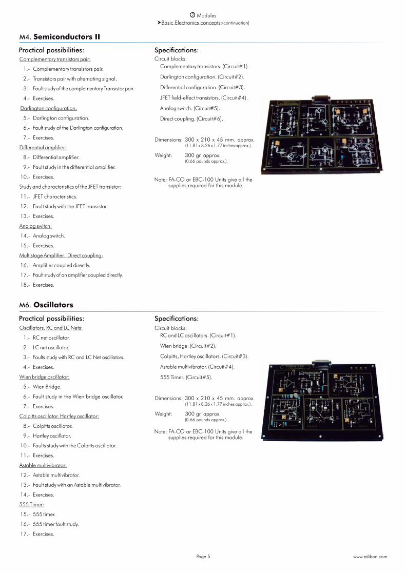
Characteristics of the PN junction: 1.- Study of the diode. 2.- Fault Study in diodes. 3.- Exercises.The diode as a rectifier element: 4.- Half wave rectifier. 5.- Study of faults in Rectifier circuit. 6.- Bridge rectifier. 7.- Study of faults in bridge rectifier. 8.- Exercises.The Zener diode: 9.- Voltage regulator with a Zener diode. 10.- Study of faults in Zener circuit. 11.- Exercises.Study and characteristics of the transistor: 12.- Study of the transistor. 13.- Study of the fault in the transistor. 14.- Exercises.Transistor characteristics operating as a switch: 15.- Study of the transistor. 16.- Exercises.Common emitter amplifier: 17.- Study of the common emitter NPN amplifier. 18.- Fault Study in Amplifier circuit. 19.- Study of the common emitter PNP amplifier. 20.- Exercises. Additional Possibilities: Voltage Doubler. Power Supply filtering.
Diode. (Circuit#1). Signal filtration. (Circuit#2). Diodes bridge. (Circuit#3). Zener diode. (Circuit#4). BJT transistor. (Circuit#5). NPN and PNP as switch. (Circuit#6). NPN amplification. (Circuit#7). PNP amplification. (Circuit#8). Sources. Load. Channels.
Dimensions: 300 x 210 x 45 mm. approx. (11.81 x 8.26 x 1.77 inches approx.).
Weight: 300 gr. approx. (0.66 pounds approx.).
Power Supply1
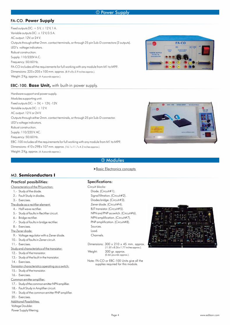
FA-CO. Power Supply
Fixed outputs DC: + 5 V, ± 12 V, 1 A.
Variable outputs DC: ± 12 V, 0.5 A.
AC output: 12V. or 24 V.
Outputs through either 2mm. contact terminals, or through 25 pin Sub-D connectors (2 outputs).
LED’s voltage indicators.
Robust construction.
Supply: 110/220V A.C.
Frequency: 50/60 Hz.
FA-CO includes all the requirements for full working with any module from M1 to M99.
Dimensions: 225 x 205 x 100 mm. approx. (8.9 x 8 x 3.9 inches approx.).
Weight: 2 Kg. approx. (4.4 pounds approx.).
EBC-100. Base Unit, with built-in power supply.
Hardware support and power supply.
Modules supporting unit.
Fixed outputs DC: + 5V, + 12V, -12V.
Variable outputs DC: ± 12 V.
AC output: 12 V. or 24 V.
Outputs through either 2mm. contact terminals, or through 25 pin Sub-D connector.
LED’s voltage indicators.
Robust construction.
Supply: 110/220 V. AC.
Frequency: 50/60 Hz.
EBC-100 includes all the requirements for full working with any module from M1 to M99.
Dimensions: 410 x 298 x 107 mm. approx. (16.1 x 11.7 x 4.2 inches approx.).
Weight: 2 Kg. approx. (4.4 pounds approx.).
2 Modules
Basic Electronics concepts
Practical possibilities:Circuit blocks:
M3. Semiconductors I
Note: FA-CO or EBC-100 Units give all the supplies required for this module.
www.edibon.comPage 4
Specifications:
Oscillators. RC and LC Nets:
1.- RC net oscillator.
2.- LC net oscillator.
3.- Faults study with RC and LC Net oscillators.
4.- Exercises.
Wien bridge oscillator:
5.- Wien Bridge.
6.- Fault study in the Wien bridge oscillator.
7.- Exercises.
Colpitts oscillator. Hartley oscillator:
8.- Colpitts oscillator.
9.- Hartley oscillator.
10.- Faults study with the Colpitts oscillator.
11.- Exercises.
Astable multivibrator:
12.- Astable multivibrator.
13.- Fault study with an Astable multivibrator.
14.- Exercises.
555 Timer:
15.- 555 timer.
16.- 555 timer fault study.
17.- Exercises.
Practical possibilities:Complementary transistors pair:
1.- Complementary transistors pair.
2.- Transistors pair with alternating signal.
3.- Fault study of the complementary Transistor pair.
4.- Exercises.
Darlington configuration:
5.- Darlington configuration.
6.- Fault study of the Darlington configuration.
7.- Exercises.
Differential amplifier:
8.- Differential amplifier.
9.- Fault study in the differential amplifier.
10.- Exercises.
Study and characteristics of the JFET transistor:
11.- JFET characteristics.
12.- Fault study with the JFET transistor.
13.- Exercises.
Analog switch:
14.- Analog switch.
15.- Exercises.
Multistage Amplifier. Direct coupling:
16.- Amplifier coupled directly.
17.- Fault study of an amplifier coupled directly.
18.- Exercises.
Complementary transistors. (Circuit#1).
Darlington configuration. (Circuit#2).
Differential configuration. (Circuit#3).
JFET field-effect transistors. (Circuit#4).
Analog switch. (Circuit#5).
Direct coupling. (Circuit#6).
Dimensions: 300 x 210 x 45 mm. approx. (11.81 x 8.26 x 1.77 inches approx.).
Weight: 300 gr. approx. (0.66 pounds approx.).
Circuit blocks:
M4. Semiconductors II
Note: FA-CO or EBC-100 Units give all the supplies required for this module.
2 ModulesBasic Electronics concepts:(continuation)
www.edibon.comPage 5
Practical possibilities:
M6. Oscillators
RC and LC oscillators. (Circuit#1).
Wien bridge. (Circuit#2).
Colpitts, Hartley oscillators. (Circuit#3).
Astable multivibrator. (Circuit#4).
555 Timer. (Circuit#5).
Dimensions: 300 x 210 x 45 mm. approx. (11.81 x 8.26 x 1.77 inches approx.).
Weight: 300 gr. approx. (0.66 pounds approx.).
Circuit blocks:
Note: FA-CO or EBC-100 Units give all the supplies required for this module.
Specifications:
Specifications:
Practical possibilities:
M8. Filters
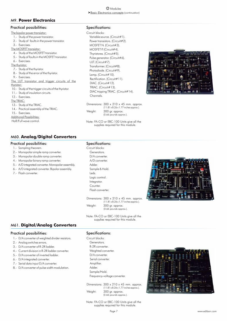
RC and LC filter responses: 1.- Frequency response. 2.- Low-pass filter. 3.- High-pass filter. 4.- LC Circuit. 5.- Study of Error in Low-pass filter. 6.- Study of Error in High-pass filter. 7.- Exercises theoretical/practical.T-shaped Filter: 8.- Filter with double T link. 9.- Generator circuit of the signal. 10.- Study of Error in RC filter with double T. 11.- Exercises theoretical/practical.Active filters: 12.- Low-pass filter. 13.- Low-pass filter with load and operational
amplifier. 14.- High-pass filter. 15.- High-pass filter with load and operational
amplifier. 16.- The attenuation is cumulative. 17.- Use of Operational Amplifier. 18.- Study of Faults in filters. 19.- Exercises theoretical/practical.Association of filters: 20.- Behaviour of the filter. 21.- Filter of distorted signal. 22.- Filter in cascade; low pass filter and
high pass filter. 23.- Filter in parallel. 24.- Study of Error in filters. 25.- Exercises theoretical/practical. Additional Possibilities: Band-Pass and Band-Stop Filters.
RC filters. (Circuit#1). LC filter. (Circuit#2). T-shaped filter. (Circuit#3). Active filters. (Circuit#4). Association of filters. Distorted signal
filters. (Circuit#5 and Circuit#6).
Dimensions: 300 x 210 x 45 mm. approx. (11.81 x 8.26 x 1.77 inches approx.).
Weight: 300 gr. approx. (0.66 pounds approx.).
Circuit blocks:
Note: FA-CO or EBC-100 Units give all the supplies required for this module.
2 ModulesBasic Electronics concepts:(continuation)
www.edibon.comPage 6
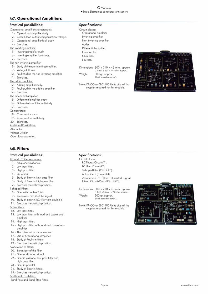
Operational amplifier characteristics: 1.- Operational amplifier study. 2.- Closed-loop output compensation voltage. 3.- Operational amplifier fault study. 4.- Exercises.The inverting amplifier: 5.- Inverting amplifier study. 6.- Inverting amplifier fault study. 7.- Exercises.The non-inverting amplifier: 8.- Study of the non-inverting amplifier. 9.- Voltage follower. 10.- Fault study in the non-inverting amplifier. 11.- Exercises.The adder amplifier: 12.- Adding amplifier study. 13.- Fault study in the adding amplifier. 14.- Exercises.The differential amplifier: 15.- Differential amplifier study. 16.- Differential amplifier fault study. 17.- Exercises.Comparators: 18.- Comparator study. 19.- Comparators fault study. 20.- Exercises.Additional Possibilities: Attenuator. Voltage Divider. Open-loop operation.
Practical possibilities:Circuit blocks:
M7. Operational Amplifiers
Operational amplifier. Inverting amplifier. Non-inverting amplifier. Adder. Differential amplifier. Comparator. Channels. Sources.
Dimensions: 300 x 210 x 45 mm. approx. (11.81 x 8.26 x 1.77 inches approx.).
Weight: 300 gr. approx. (0.66 pounds approx.).
Note: FA-CO or EBC-100 Units give all the supplies required for this module.
Specifications:
Specifications:
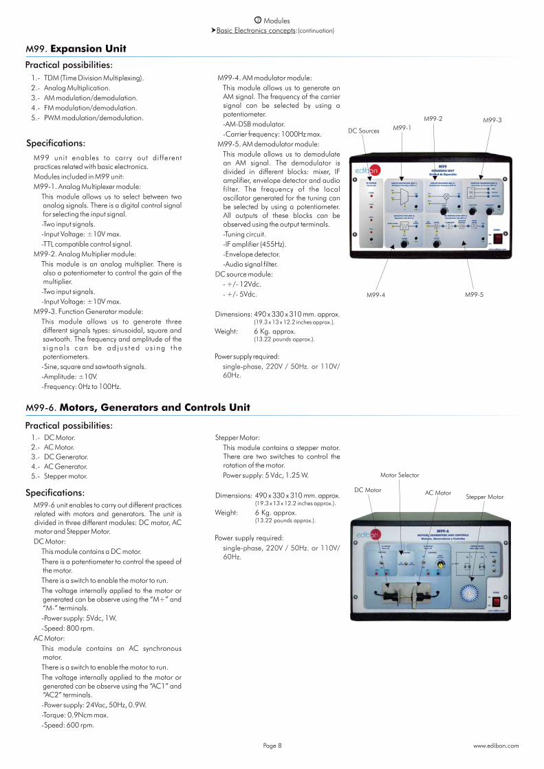
The bipolar power transistor: 1.- Study of the power transistor. 2.- Study of faults in the power transistor. 3.- Exercises.The MOSFET transistor: 4.- Study of the MOSFET transistor. 5.- Study of faults in the MOSFET transistor. 6.- Exercises.The thyristor: 7.- Study of the thyristor. 8.- Study of the error of the thyristor. 9.- Exercises.The UJT transistor and trigger circuits of the thyristor: 10.- Study of the trigger circuits of the thyristor. 11.- Study of insulation circuits. 12.- Exercises.The TRIAC: 13.- Study of the TRIAC. 14.- Practical assembly of the TRIAC. 15.- Exercises.Additional Possibilities: Half/Full wave control.
Practical possibilities:
Practical possibilities:
M60. Analog/Digital Converters
M61. Digital/Analog Converters
1.- Sampling theorem. 2.- Monopolar simple ramp converter. 3.- Monopolar double ramp converter. 4.- Monopolar binary ramp converter. 5.- A/D integrated converter. Monopolar assembly. 6.- A/D integrated converter. Bipolar assembly. 7.- Flash converter.
1.- D/A converter of weighted divider resistors. 2.- Analog switches errors. 3.- D/A converter of R-2R ladder. 4.- Current division in R-2R ladder converter. 5.- D/A converter of inverted ladder. 6.- D/A integrated converter. 7.- Serial data input D/A converter. 8.- D/A converter of pulse width modulation.
Note: FA-CO or EBC-100 Units give all the supplies required for this module.
Note: FA-CO or EBC-100 Units give all the supplies required for this module.
Circuit blocks: Generators. D/A converter. A/D converter. Adder. Sample & Hold. Leds. Logic control. Integrator. Counter. Flash converter.
Dimensions: 300 x 210 x 45 mm. approx. (11.81 x 8.26 x 1.77 inches approx.).
Weight: 300 gr. approx. (0.66 pounds approx.).
Circuit blocks: Generators. R-2R converter. Weighted converter. D/A converter. Serial converter. Amplifier. Adder. Sample/Hold. Frequency-voltage converter.
Dimensions: 300 x 210 x 45 mm. approx. (11.81 x 8.26 x 1.77 inches approx.).
Weight: 300 gr. approx. (0.66 pounds approx.).
2 ModulesBasic Electronics concepts:(continuation)
www.edibon.comPage 7
Practical possibilities:Circuit blocks:
M9. Power Electronics
Variable source. (Circuit#1). Power transistors. (Circuit#2). MOSFET N. (Circuit#3). MOSFET P. (Circuit#4). Thyristores. (Circuit#5). Pulse generator. (Circuit#6). UJT. (Circuit#7). Transformer. (Circuit#8). Photodiode. (Circuit#9). Lamp. (Circuit#10). Rectification. (Circuit#11). DIAC. (Circuit#12). TRIAC. (Circuit#13). DIAC tripping TRIAC. (Circuit#14). Channels.
Dimensions: 300 x 210 x 45 mm. approx. (11.81 x 8.26 x 1.77 inches approx.).
Weight: 300 gr. approx. (0.66 pounds approx.).
Note: FA-CO or EBC-100 Units give all the supplies required for this module.
Specifications:
Specifications:
Specifications:
1.- TDM (Time Division Multiplexing). 2.- Analog Multiplication. 3.- AM modulation/demodulation. 4.- FM modulation/demodulation. 5.- PWM modulation/demodulation.
M99 unit enables to carry out different practices related with basic electronics.
Modules included in M99 unit: M99-1. Analog Multiplexer module: This module allows us to select between two
analog signals. There is a digital control signal for selecting the input signal.
-Two input signals. -Input Voltage: 10V max.± -TTL compatible control signal. M99-2. Analog Multiplier module: This module is an analog multiplier. There is
also a potentiometer to control the gain of the multiplier.
-Two input signals. -Input Voltage: 10V max.± M99-3. Function Generator module: This module allows us to generate three
different signals types: sinusoidal, square and sawtooth. The frequency and amplitude of the s i gna l s can be ad ju s t ed u s i ng t he potentiometers.
-Sine, square and sawtooth signals. -Amplitude: 10V.± -Frequency: 0Hz to 100Hz.
M99-4. AM modulator module: This module allows us to generate an
AM signal. The frequency of the carrier signal can be selected by using a potentiometer.
-AM-DSB modulator. -Carrier frequency: 1000Hz max. M99-5. AM demodulator module: This module allows us to demodulate
an AM signal. The demodulator is divided in different blocks: mixer, IF amplifier, envelope detector and audio filter. The frequency of the local oscillator generated for the tuning can be selected by using a potentiometer. All outputs of these blocks can be observed using the output terminals.
-Tuning circuit. -IF amplifier (455Hz). -Envelope detector. -Audio signal filter. DC source module: - +/- 12Vdc. - +/- 5Vdc.
Dimensions: 490 x 330 x 310 mm. approx. (19.3 x 13 x 12.2 inches approx.).
Weight: 6 Kg. approx. (13.22 pounds approx.).
Power supply required: single-phase, 220V / 50Hz. or 110V/
60Hz.
M99. Expansion Unit
2 ModulesBasic Electronics concepts:(continuation)
www.edibon.com
Practical possibilities:
Specifications:
M99-6. Motors, Generators and Controls Unit
Practical possibilities: 1.- DC Motor. 2.- AC Motor. 3.- DC Generator. 4.- AC Generator. 5.- Stepper motor.
M99-6 unit enables to carry out different practices related with motors and generators. The unit is divided in three different modules: DC motor, AC motor and Stepper Motor.
DC Motor: This module contains a DC motor. There is a potentiometer to control the speed of
the motor. There is a switch to enable the motor to run. The voltage internally applied to the motor or
generated can be observe using the “M+” and “M-” terminals.
-Power supply: 5Vdc, 1W. -Speed: 800 rpm. AC Motor: This module contains an AC synchronous
motor. There is a switch to enable the motor to run. The voltage internally applied to the motor or
generated can be observe using the “AC1” and “AC2” terminals.
-Power supply: 24Vac, 50Hz, 0.9W. -Torque: 0.9Ncm max. -Speed: 600 rpm.
Stepper Motor: This module contains a stepper motor.
There are two switches to control the rotation of the motor.
Power supply: 5 Vdc, 1.25 W.
Dimensions: 490 x 330 x 310 mm. approx. (19.3 x 13 x 12.2 inches approx.).
Weight: 6 Kg. approx. (13.22 pounds approx.).
Power supply required: single-phase, 220V / 50Hz. or 110V/
60Hz.
Specifications:
Page 8
M99-1M99-2 M99-3
M99-4 M99-5
DC Motor AC Motor
Motor Selector
Stepper Motor
DC Sources

Digital Electronics
Practical possibilities:
Practical possibilities:
M11. Digital Electronics Fundamentals
M10. Digital Systems and Converters
Analog switching. The bistable, astable and monostable family: 1.- Characteristics of an analog switch. 2.- Study of the errors in the Analog Multiplexer. 3.- Characteristics of an S-R type Latch circuit. 4.- Error Study in the bistable. 5.- Characteristics of an astable circuit. 6.- Error study in the astable. 7.- Characteristics of a monostable circuit. 8.- Theoretical/practical exercises.Binary/BCD Counters & 7-segments Displays: 9.- Characteristics of Binary UP/DOWN Counter
and 7-Segment Display. 10.- Error Study in the binary counter. 11.- Characteristics of the BCD UP/DOWN
counter and 7-Segment Display. 12.- Error Study in the BCD counter. 13.- Theoretical/practical exercises.Comparators and analog integrators: 14.- Characteristics of an analog comparator. 15.- Analog integrator. 16.- Error Study in the analog integrator. 17.- Triangular wave generation. 18.- Theoretical/practical exercises.A/D and D/A conversion: 19.- D/A Converter. 20.- A/D Converter. 21.- Theoretical/practical exercises.Applications: 22.- Random number generator. 23.- Measuring the time between two events. 24.- Theoretical/practical exercises.Additional Possibilities: Synchronous/Asynchronous Counter.
Potentiometer. BCD counter. Binary counter. Logic monitors. Display. Shot Clocks. Logic switches. Flip Flop RS. Analog multiplexer. Analog integrator. Monostable. Logic gates. Astable. Analog comparator. D/A converter. Channels.
Dimensions: 300 x 210 x 45 mm. approx. (11.81 x 8.26 x 1.77 inches approx.).
Weight: 300 gr. approx. (0.66 pounds approx.).
Circuit blocks:
Numbers systems: 1.- Voltage measurement in a circuit of sources. 2.- Fault study in the source circuit. 3.- Exercises.Logical circuits: 4.- Logical Diode. 5.- Fault study in Sources. 6.- Logic with transistor and diodes. 7.- Fault study in transistor/diode circuit. 8.- Exercises.TTL gates: 9.- Basic function gates. 10.- Fault study in TTL circuit. 11.- Fault study in Logic Gates. 12.- Exercises.CMOS gates: 13.- Basic function gates. 14.- Fault study in CMOS circuit. 15.- Exercises.Boolean Algebra and logical functions: 16.- Study of use of Circuit #3. 17.- Exercises.Open collector gates: 18.- Study of the use of Circuit #5. 19.- Exercises.Others types of integrated gates: 20.- Study of simple operations with a Schmitt
Trigger inverter. 21.- Operation study of a three-state buffer. 22.- Study of the fault in the Circuit #7. 23.- Exercises. Additional Possibilities: JK Flip-Flop. Control of Data Bus.
Logical source. (Circuit#1). Sources. (Circuit#2). TTL logical gates. (Circuit#3). CMOS logical gates. (Circuit#4). Open collector gates. (Circuit#5). Schmitt trigger. (Circuit#6). Three-states. (Circuit#7). Channels. Sources. Indicators.
Dimensions: 300 x 210 x 45 mm. approx. (11.81 x 8.26 x 1.77 inches approx.).
Weight: 300 gr. approx. (0.66 pounds approx.).
Circuit blocks:
Note: FA-CO or EBC-100 Units give all the supplies required for this module.
Note: FA-CO or EBC-100 Units give all the supplies required for this module.
2 Modules
www.edibon.comPage 9
Specifications:
Specifications:
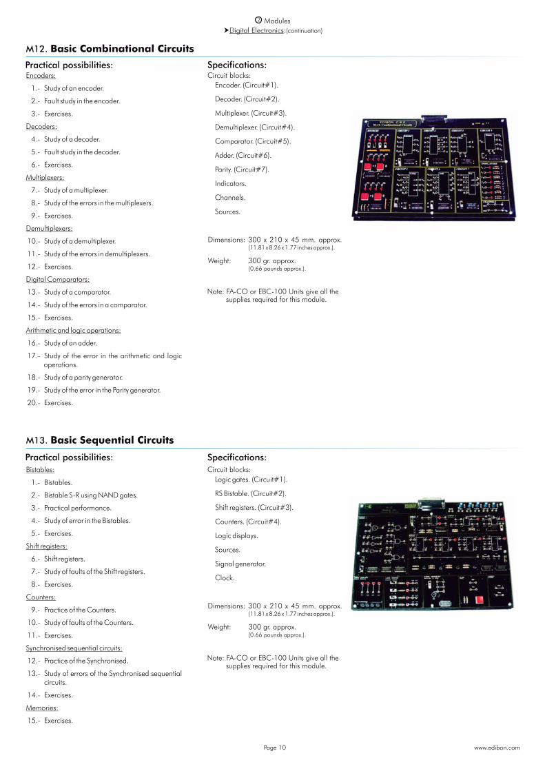
Encoders:
1.- Study of an encoder.
2.- Fault study in the encoder.
3.- Exercises.
Decoders:
4.- Study of a decoder.
5.- Fault study in the decoder.
6.- Exercises.
Multiplexers:
7.- Study of a multiplexer.
8.- Study of the errors in the multiplexers.
9.- Exercises.
Demultiplexers:
10.- Study of a demultiplexer.
11.- Study of the errors in demultiplexers.
12.- Exercises.
Digital Comparators:
13.- Study of a comparator.
14.- Study of the errors in a comparator.
15.- Exercises.
Arithmetic and logic operations:
16.- Study of an adder.
17.- Study of the error in the arithmetic and logic operations.
18.- Study of a parity generator.
19.- Study of the error in the Parity generator.
20.- Exercises.
www.edibon.comPage 10
Practical possibilities:
M12. Basic Combinational Circuits
Circuit blocks: Encoder. (Circuit#1).
Decoder. (Circuit#2).
Multiplexer. (Circuit#3).
Demultiplexer. (Circuit#4).
Comparator. (Circuit#5).
Adder. (Circuit#6).
Parity. (Circuit#7).
Indicators.
Channels.
Sources.
Dimensions: 300 x 210 x 45 mm. approx. (11.81 x 8.26 x 1.77 inches approx.).
Weight: 300 gr. approx. (0.66 pounds approx.).
Note: FA-CO or EBC-100 Units give all the supplies required for this module.
2 ModulesDigital Electronics:(continuation)
Bistables:
1.- Bistables.
2.- Bistable S-R using NAND gates.
3.- Practical performance.
4.- Study of error in the Bistables.
5.- Exercises.
Shift registers:
6.- Shift registers.
7.- Study of faults of the Shift registers.
8.- Exercises.
Counters:
9.- Practice of the Counters.
10.- Study of faults of the Counters.
11.- Exercises.
Synchronised sequential circuits:
12.- Practice of the Synchronised.
13.- Study of errors of the Synchronised sequential circuits.
14.- Exercises.
Memories:
15.- Exercises.
Practical possibilities:Circuit blocks:
M13. Basic Sequential Circuits
Logic gates. (Circuit#1).
RS Bistable. (Circuit#2).
Shift registers. (Circuit#3).
Counters. (Circuit#4).
Logic displays.
Sources.
Signal generator.
Clock.
Dimensions: 300 x 210 x 45 mm. approx. (11.81 x 8.26 x 1.77 inches approx.).
Weight: 300 gr. approx. (0.66 pounds approx.).
Note: FA-CO or EBC-100 Units give all the supplies required for this module.
Specifications:
Specifications:

2 ModulesDigital Electronics:(continuation)
Practical possibilities:
M14. Optoelectronics
Light transmitters and liquid crystal display (LCD): 1.- Light transmitters. 2.- Bar graph. 3.- LCD display and 7-segment display. 4.- Fault Study in light transmitters and liquid
crystal display. 5.- Exercises.Photo-conducting cells: 6.- Light dependent resistors. 7.- Alarm. 8.- Fault study on the photo-conducting cell. 9.- Exercises.Fiber optics: 10.- Fiber optics practice. 11.- Fault study using fiber optics. 12.- Exercises.Infrared: 13.- Circuit with infrared diodes. 14.- Fault study of the infrared diodes. 15.- Exercises.
Circuit blocks:
Note: FA-CO or EBC-100 Units give all the supplies required for this module.
Practical possibilities:
M41. Resistance Transducers
1.- Study of the properties of NTC for the measurement of temperature.
2.- Study of the properties of PTC for the measurement of temperature.
3.- Study of the properties of LDR for the measurement of light intensity.
4.- Study of the properties of RTD for the measurement of temperature.
5.- Study of the properties of Strain Gauge for the measurement of deformation.
This module enables to carry out different practices related with variable resistance transducers. The module has five different types of transducers: PTC, NTC, LDR, strain gauge and RTD.
On the chassis there are a lamp, a heater and the sensors. The lamp is used to control the illumination incident. The module also include a dark cover box whose aim is to avoid the environmental light noise. The heater is used to control the temperature.
Elements included: Lamp: -Voltage: 12Vdc. -Illumination intensity: 200 lumens. -Power dissipation: 5W max. Heater resistor: -Voltage: 12Vdc. -Power dissipation: 4W max. PTC: -Resistance @ 25ºC: 100 Ohm. -Operating temperature max: +70ºC. NTC: -Resistance @25ºC: 150 Ohm. -Temperature coefficient: -3.9%/ºC. -Temperature sensing range: -55 to
+150ºC.
RTD: -Resistance @ 0ºC: 100 Ohm. -Sensibility: +0.3851 Ohm/ºC. -Temperature sensing range: -220ºC
to+650ºC. LDR: -Resistance: 5.4K min., 12.6K max. -Power dissipation: 250mW max. -Peak wavelength: 550nm. Strain gauge: -Resistance: 120 Ohm. -Power dissipation: 100mW max. -Factor: 2.1 -Length: 5mm.All the connections of the different sensors and lamp are done using the 2mm terminals available on the module front panel, with diagrams describing their functions.
Dimensions: 405 x 300 x 350 mm. approx. (15.9 x 11.8 x 13.7 inches approx.).
Weight: 6 Kg. approx. (13.22 pounds approx.).
Note: FA-CO Unit gives all the supplies required for this module.
Lamp. (Circuit#1). Sources. (Circuit#2). Bar graph. (Circuit#3). LDR. (Circuit#4). Photodiodes, optic fiber. (Circuit#5). Converter. (Circuit#6). Amplifier. (Circuit#7). Differential amplifier. (Circuit#8). Infrared Photodiodes. (Circuit#9). LCD Display, 7 segment BCD. ( Circuit#10). Buzzer.
Dimensions: 300 x 210 x 45 mm. approx. (11.81 x 8.26 x 1.77 inches approx.).
Weight: 300 gr. approx. (0.66 pounds approx.).
Specifications:
Lamp
LDR
Heater
Strain gaugePTC
NTC RTD
Front panel
www.edibon.comPage 11
Specifications:
Basic Electricity concepts
Practical possibilities:
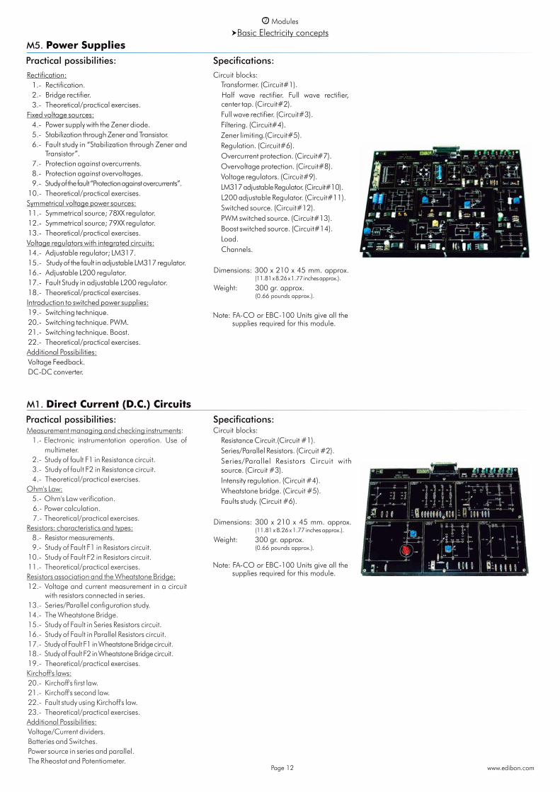
M5. Power Supplies
Rectification: 1.- Rectification. 2.- Bridge rectifier. 3.- Theoretical/practical exercises.Fixed voltage sources: 4.- Power supply with the Zener diode. 5.- Stabilization through Zener and Transistor. 6.- Fault study in “Stabilization through Zener and
Transistor”. 7.- Protection against overcurrents. 8.- Protection against overvoltages. 9.- Study of the fault “Protection against overcurrents”. 10.- Theoretical/practical exercises.Symmetrical voltage power sources: 11.- Symmetrical source; 78XX regulator. 12.- Symmetrical source; 79XX regulator. 13.- Theoretical/practical exercises.Voltage regulators with integrated circuits: 14.- Adjustable regulator; LM317. 15.- Study of the fault in adjustable LM317 regulator. 16.- Adjustable L200 regulator. 17.- Fault Study in adjustable L200 regulator. 18.- Theoretical/practical exercises.Introduction to switched power supplies: 19.- Switching technique. 20.- Switching technique. PWM. 21.- Switching technique. Boost. 22.- Theoretical/practical exercises.Additional Possibilities: Voltage Feedback. DC-DC converter.
Note: FA-CO or EBC-100 Units give all the supplies required for this module.
Circuit blocks: Transformer. (Circuit#1). Half wave rectifier. Full wave rectifier,
center tap. (Circuit#2). Full wave rectifier. (Circuit#3). Filtering. (Circuit#4). Zener limiting.(Circuit#5). Regulation. (Circuit#6). Overcurrent protection. (Circuit#7). Overvoltage protection. (Circuit#8). Voltage regulators. (Circuit#9). LM317 adjustable Regulator. (Circuit#10). L200 adjustable Regulator. (Circuit#11). Switched source. (Circuit#12). PWM switched source. (Circuit#13). Boost switched source. (Circuit#14). Load. Channels.
Dimensions: 300 x 210 x 45 mm. approx. (11.81 x 8.26 x 1.77 inches approx.).
Weight: 300 gr. approx. (0.66 pounds approx.).
Measurement managing and checking instruments: 1.- Electronic instrumentation operation. Use of multimeter. 2.- Study of fault F1 in Resistance circuit. 3.- Study of fault F2 in Resistance circuit. 4.- Theoretical/practical exercises. Ohm's Law: 5.- Ohm's Law verification. 6.- Power calculation. 7.- Theoretical/practical exercises.Resistors: characteristics and types: 8.- Resistor measurements. 9.- Study of Fault F1 in Resistors circuit. 10.- Study of Fault F2 in Resistors circuit. 11.- Theoretical/practical exercises. Resistors association and the Wheatstone Bridge: 12.- Voltage and current measurement in a circuit
with resistors connected in series. 13.- Series/Parallel configuration study. 14.- The Wheatstone Bridge. 15.- Study of Fault in Series Resistors circuit. 16.- Study of Fault in Parallel Resistors circuit. 17.- Study of Fault F1 in Wheatstone Bridge circuit. 18.- Study of Fault F2 in Wheatstone Bridge circuit. 19.- Theoretical/practical exercises. Kirchoff's laws: 20.- Kirchoff's first law. 21.- Kirchoff's second law. 22.- Fault study using Kirchoff's law. 23.- Theoretical/practical exercises.Additional Possibilities: Voltage/Current dividers. Batteries and Switches. Power source in series and parallel. The Rheostat and Potentiometer.
M1. Direct Current (D.C.) CircuitsPractical possibilities:
Circuit blocks: Resistance Circuit.(Circuit #1). Series/Parallel Resistors. (Circuit #2). Series/Parallel Resistors Circuit with
source. (Circuit #3). Intensity regulation. (Circuit #4). Wheatstone bridge. (Circuit #5). Faults study. (Circuit #6).
Dimensions: 300 x 210 x 45 mm. approx. (11.81 x 8.26 x 1.77 inches approx.).
Weight: 300 gr. approx. (0.66 pounds approx.).
Note: FA-CO or EBC-100 Units give all the supplies required for this module.
2 Modules
www.edibon.comPage 12
Specifications:
Specifications:
Alternating signal characteristics. Instruments: 1.- Waveforms study in AC. 2.- Introduction of anomalies in the Wave form
circuit. 3.- Study of Faults in the Waveform circuit. 4.- Relation between peak values and RMS for
sinusoidal waves. 5.- Resistance in a sinusoidal alternating current. 6.- Measurements using the oscilloscope. 7.- Voltage and current phase angles for resistors
in sinusoidal alternating current. 8.- Sinusoidal AC. resistors in series. 9.- Sinusoidal AC. resistors in parallel. 10.- Exercises.Behaviour of AC. capacitors and inductors: 11.- Capacitance with square waveform and
sinusoidal input current. 12.- Inductance with square waveform and a
sinusoidal input voltage. 13.- Reactive reactance, Xc, variations with the
frequency. 14.- Study of faults in capacitors. 15.- Reactive capacitance variations with the
capacitance. 16.- AC. capacitors in parallel. 17.- AC. capacitors in series. 18.- AC. capacitors as voltage dividers. 19.- Inductance in an AC circuit. 20.- Inductive reactance variations with the
inductance. 21.- Inductors in series in an AC. circuit. 22.- Exercises.Basic theorems and capacitance and inductance circuits: 23.- AC. Resistor-Capacitor circuits in series.24.- AC. Resistor-Capacitor circuits in parallel. 25.- AC. Resistor-Inductor circuits in series. 26.- Study of Fault 1 in the Circuit #3. 27.- Study of Fault 2 in the Circuit #3. 28.- AC. Resistor-Inductor circuits in parallel. 29.- Exercises.
RLC Circuits: 30.- Resistance-Capacitance Filters. 31.- Filters inductive resistance. Low-
Pass and High- Pass filters. 32.- Exercises.Resonance: 33.- AC. L-C Circuits in parallel with
low impedance source. 34.- Study of Fault 1 in the resonance
circuit. 35.- Study of Fault 2 in the resonance
circuit. 36.- AC. L-C Circuits in parallel with
high impedance source. 37.- Circuit frequency response and
bandwidth. 38.- AC. R-L-C Circuits in series. 39.- Exercises.The transformer: 40.- The transformer. 41.- The transformer with load. 42.- Current measurement in the
secondary Transformer with charge. 43.- Exercises.
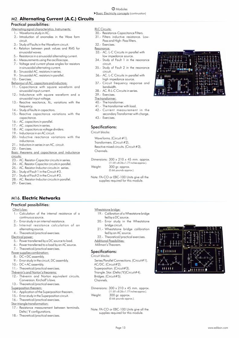
Practical possibilities:M2. Alternating Current (A.C.) Circuits
Circuit blocks:
Wave forms. (Circuit #1). Transformers. (Circuit #2). Reactive mixed circuits. (Circuit #3). Channels.
Dimensions: 300 x 210 x 45 mm. approx. (11.81 x 8.26 x 1.77 inches approx.).
Weight: 300 gr. approx. (0.66 pounds approx.).
Note: FA-CO or EBC-100 Units give all the supplies required for this module.
2 ModulesBasic Electricity concepts:(continuation)
Practical possibilities:
M16. Electric Networks
Ohm’s law: 1.- Calculation of the internal resistance of a
continuous source. 2.- Error study in an internal resistance. 3.- Internal resistance calculation of an
alternating source. 4.- Theoretical/practical exercises.Electrical power: 5.- Power transferred by a DC source to load. 6.- Power transferred to a load by an AC source. 7.- Theoretical/practical exercises.Power supplies combination: 8.- DC+DC assembly. 9.- Error study in the circuit, DC assembly. 10.- DC+AC assembly. 11.- Theoretical/practical exercises.Thévenin’s and Norton’s theorems: 12.- Thévenin and Norton equivalent circuits.
Conversion. Kirchoff’s laws. 13.- Theoretical/practical exercises.Superposition theorem: 14.- Application of the Superposition theorem. 15.- Error study in the Superposition circuit. 16.- Theoretical/practical exercises.Star-triangle transformation: 17.- Resistance measurement between terminals.
Delta| configurations. 18.- Theoretical/practical exercises.
Wheatstone bridge: 19.- Calibration of a Wheatstone bridge
fed by a DC source. 20.- Error study in the Wheatstone
bridge circuit. 21.- Wheatstone bridge calibration
fed by an AC source. 22.- Theoretical/practical exercises. Additional Possibilities: Millman’s Theorem.
Series/Parallel Connections. (Circuit#1). AC/DC. (Circuit#2). Superposition. (Circuit#3). Triangle .Star. (Delta|)(Circuit#4). Bridges. (Circuit#5). Channels.
Dimensions: 300 x 210 x 45 mm. approx. (11.81 x 8.26 x 1.77 inches approx.).
Weight: 300 gr. approx. (0.66 pounds approx.).
Circuit blocks:
Note: FA-CO or EBC-100 Units give all the supplies required for this module.
www.edibon.comPage 13
Specifications:
Specifications:
2 ModulesBasic Electricity concepts:(continuation)
Practical possibilities:
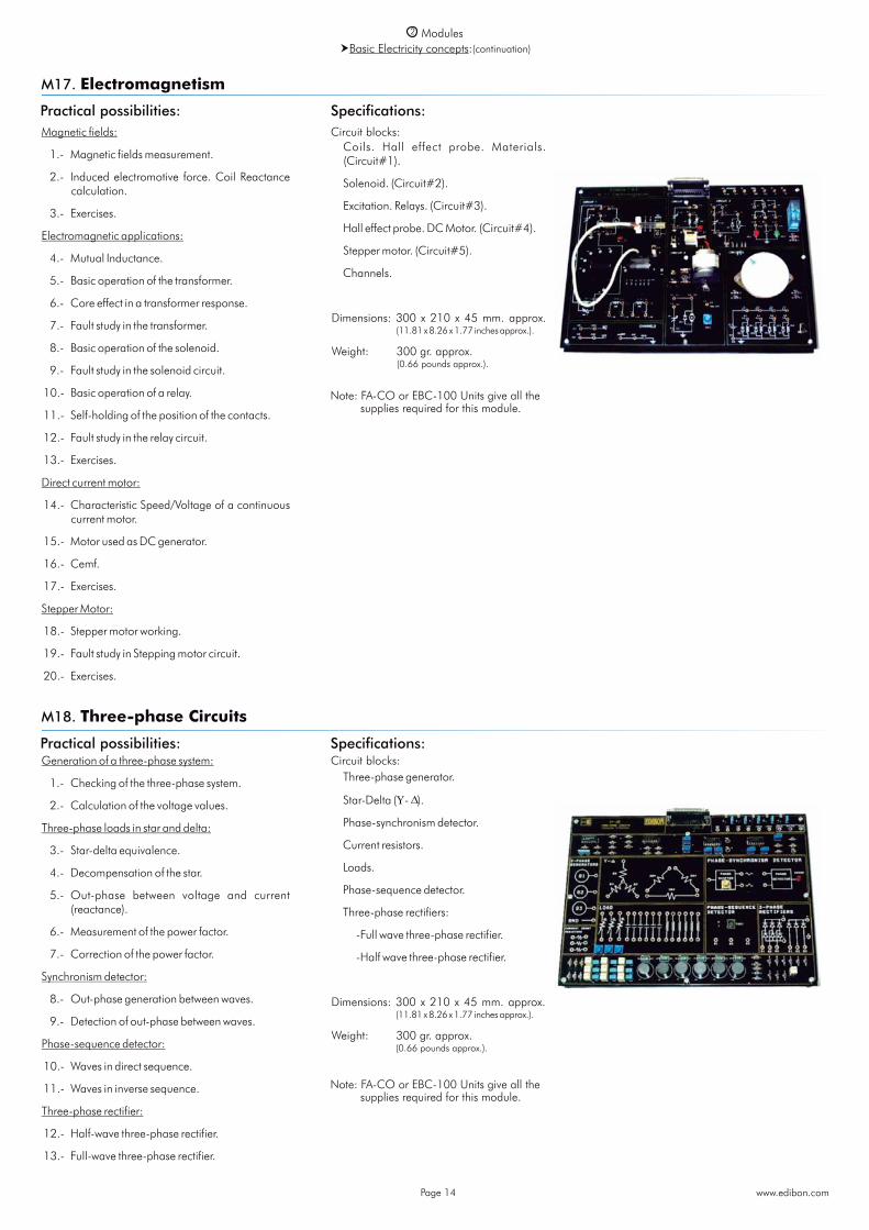
M17. Electromagnetism
Magnetic fields:
1.- Magnetic fields measurement.
2.- Induced electromotive force. Coil Reactance calculation.
3.- Exercises.
Electromagnetic applications:
4.- Mutual Inductance.
5.- Basic operation of the transformer.
6.- Core effect in a transformer response.
7.- Fault study in the transformer.
8.- Basic operation of the solenoid.
9.- Fault study in the solenoid circuit.
10.- Basic operation of a relay.
11.- Self-holding of the position of the contacts.
12.- Fault study in the relay circuit.
13.- Exercises.
Direct current motor:
14.- Characteristic Speed/Voltage of a continuous current motor.
15.- Motor used as DC generator.
16.- Cemf.
17.- Exercises.
Stepper Motor:
18.- Stepper motor working.
19.- Fault study in Stepping motor circuit.
20.- Exercises.
Circuit blocks: Coils. Hall effect probe. Materials.
(Circuit#1).
Solenoid. (Circuit#2).
Excitation. Relays. (Circuit#3).
Hall effect probe. DC Motor. (Circuit#4).
Stepper motor. (Circuit#5).
Channels.
Dimensions: 300 x 210 x 45 mm. approx. (11.81 x 8.26 x 1.77 inches approx.).
Weight: 300 gr. approx. (0.66 pounds approx.).
Note: FA-CO or EBC-100 Units give all the supplies required for this module.
Practical possibilities:
M18. Three-phase Circuits
Generation of a three-phase system:
1.- Checking of the three-phase system.
2.- Calculation of the voltage values.
Three-phase loads in star and delta:
3.- Star-delta equivalence.
4.- Decompensation of the star.
5.- Out-phase between voltage and current (reactance).
6.- Measurement of the power factor.
7.- Correction of the power factor.
Synchronism detector:
8.- Out-phase generation between waves.
9.- Detection of out-phase between waves.
Phase-sequence detector:
10.- Waves in direct sequence.
11.- Waves in inverse sequence.
Three-phase rectifier:
12.- Half-wave three-phase rectifier.
13.- Full-wave three-phase rectifier.
Circuit blocks: Three-phase generator.
Star-Delta (- ).
Phase-synchronism detector.
Current resistors.
Loads.
Phase-sequence detector.
Three-phase rectifiers:
-Full wave three-phase rectifier.
-Half wave three-phase rectifier.
Dimensions: 300 x 210 x 45 mm. approx. (11.81 x 8.26 x 1.77 inches approx.).
Weight: 300 gr. approx. (0.66 pounds approx.).
Note: FA-CO or EBC-100 Units give all the supplies required for this module.
www.edibon.comPage 14
Specifications:
Specifications:

Electronics Applications
2 Modules
www.edibon.comPage 15
The integrated circuit temperature transducer:
1.- Characteristics of an integrated temperature circuit.
2.- Construction of a digital thermometer.
The (T.D.R.) Platinum transducer:
3.- Characteristics of a platinum Temperature Dependent Resistance (T.D.R) transducer.
The N.T.C (Negative Temperature Coefficient) thermistor:
4.- Characteristics of an N.T.C thermistor.
5.- N.T.C Characteristics. Thermistor used in an alarm circuit (double thermistor).
The “K” type thermocouple temperature thermistor:
6.- Characteristics of a ‘K’ type thermocouple.
The Pressure transducer:
7.- Characteristic of a pressure transducer.
M49. Applications of Temperature and Pressure
Practical possibilities:Circuit blocks: Counter/Timer.
Thermometric probes (Type ‘K’, IC, Thermistor, Platinum RTD).
Wheatstone bridge.
Carbon track.
Buzzer.
Pressure transducer.
Electronic switch.
Voltage to frequency converter.
Differentiator.
AC Amplifier.
Amplifier (Adjust offset. Gain).
Comparator. Hyteresis.
Instrumental amplifier.
Buffer.
x100 amplifier.
Dimensions: 300 x 210 x 45 mm. approx. (11.81 x 8.26 x 1.77 inches approx.).
Weight: 300 gr. approx. (0.66 pounds approx.).
Note: FA-CO or EBC-100 Units give all the supplies required for this module.
Specifications:
Practical possibilities:
M44. Applications of Light
Note: FA-CO Unit gives all the supplies required for this module.
Specifications:
1.- Study of the equivalent electrical circuit of a photodiode.
2.- Study of the V-I characteristic of a photodiode. 3.- Study of the photovoltaic and photoconductive
modes of a photodiode. 4.- Study the “ON/OFF” operation mode of a
phototransistor. 5.- Measurement of light intensity using a
photovoltaic cell. 6.- Study of the properties of light dependent
resistors (LDR) 7.- Study of different applications using IR sensors.
This module enables to carry out different practices related with the light intensity measurement.
The module has five different types of light sensor s : pho tod iode , pho to t rans i s to r, photovoltaic cell, light dependent resistor and infrared sensor.
Studying the different sensors is possible to compare their operation and determine their corresponding strengths and weaknesses.
On the chassis there are two holders with a lamp and the sensors. The lamp is used to control the illumination incident. The module also includes a dark cover box whose aim is to avoid the environmental light noise.
Elements included: Lamp: -Voltage: 12Vdc. -Power dissipation: 5W max. -Illumination intensity: 200 lumens. Photodiode: -Power dissipation: 250 mW max.
-Sensibility: 0.34A/W. -Dark current: 200 nA. -Peak wavelength: 550 nm. -Reverse voltage: 10V max. Phototransistor: -Current collector max.: 20 mA. -Peak wavelength: 570 nm. LDR: -Power dissipation: 250 mW max. -Peak wavelength: 550 nm. Photovoltaic cell: -Power dissipation: 250 mW max. -Peak wavelength: 550 nm. IR Emitter: -Power dissipation: 470 mW max. -Current max.: 200 mA. -Peak wavelength: 880 nm. IR Receiver: -Power dissipation: 470 mW max. -Current max.: 200 mA. -Peak wavelength: 880 nm.All the connections of the different sensors and lamp are done using the 2 mm. terminals available on the module front panel, with diagrams describing their functions.
Dimensions: 405 x 300 x 350 mm. approx. (15.9 x 11.8 x 13.7 inches approx.).
Weight: 6 Kg. approx. (13.22 pounds approx.).
Front panel
Lamp
Photovoltaic cell
Photodiode
InfraRed sensorLDR
Panels
2 ModulesElectronics Applications:(continuation)
www.edibon.comPage 16
Practical possibilities:
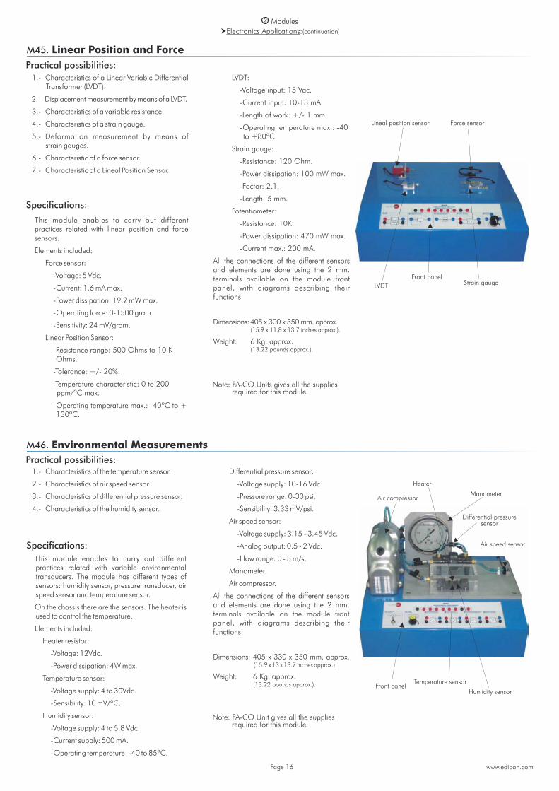
M45. Linear Position and Force
1.- Characteristics of a Linear Variable Differential Transformer (LVDT).
2.- Displacement measurement by means of a LVDT.
3.- Characteristics of a variable resistance.
4.- Characteristics of a strain gauge.
5.- Deformation measurement by means of strain gauges.
6.- Characteristic of a force sensor.
7.- Characteristic of a Lineal Position Sensor.
This module enables to carry out different practices related with linear position and force sensors.
Elements included:
Force sensor:
-Voltage: 5 Vdc.
-Current: 1.6 mA max.
-Power dissipation: 19.2 mW max.
-Operating force: 0-1500 gram.
-Sensitivity: 24 mV/gram.
Linear Position Sensor:
-Resistance range: 500 Ohms to 10 K Ohms.
-Tolerance: +/- 20%.
-Temperature characteristic: 0 to 200 ppm/ºC max.
-Operating temperature max.: -40ºC to + 130ºC.
LVDT:
-Voltage input: 15 Vac.
-Current input: 10-13 mA.
-Length of work: +/- 1 mm.
-Operating temperature max.: -40 to +80ºC.
Strain gauge:
-Resistance: 120 Ohm.
-Power dissipation: 100 mW max.
-Factor: 2.1.
-Length: 5 mm.
Potentiometer:
-Resistance: 10K.
-Power dissipation: 470 mW max.
-Current max.: 200 mA.
All the connections of the different sensors and elements are done using the 2 mm. terminals available on the module front panel, with diagrams describing their functions.
Dimensions: 405 x 300 x 350 mm. approx. (15.9 x 11.8 x 13.7 inches approx.).
Weight: 6 Kg. approx. (13.22 pounds approx.).
Note: FA-CO Units gives all the supplies required for this module.
Specifications:
Lineal position sensor Force sensor
LVDT Strain gaugeFront panel
M46. Environmental MeasurementsPractical possibilities: 1.- Characteristics of the temperature sensor.
2.- Characteristics of air speed sensor.
3.- Characteristics of differential pressure sensor.
4.- Characteristics of the humidity sensor.
This module enables to carry out different practices related with variable environmental transducers. The module has different types of sensors: humidity sensor, pressure transducer, air speed sensor and temperature sensor.
On the chassis there are the sensors. The heater is used to control the temperature.
Elements included:
Heater resistor:
-Voltage: 12Vdc.
-Power dissipation: 4W max.
Temperature sensor:
-Voltage supply: 4 to 30Vdc.
-Sensibility: 10 mV/ºC.
Humidity sensor:
-Voltage supply: 4 to 5.8 Vdc.
-Current supply: 500 mA.
-Operating temperature: -40 to 85ºC.
Differential pressure sensor:
-Voltage supply: 10-16 Vdc.
-Pressure range: 0-30 psi.
-Sensibility: 3.33 mV/psi.
Air speed sensor:
-Voltage supply: 3.15 - 3.45 Vdc.
-Analog output: 0.5 - 2 Vdc.
-Flow range: 0 - 3 m/s.
Manometer.
Air compressor.
All the connections of the different sensors and elements are done using the 2 mm. terminals available on the module front panel, with diagrams describing their functions.
Dimensions: 405 x 330 x 350 mm. approx. (15.9 x 13 x 13.7 inches approx.).
Weight: 6 Kg. approx. (13.22 pounds approx.).
Note: FA-CO Unit gives all the supplies required for this module.
Specifications:
Manometer
Differential pressuresensor
Air speed sensor
Air compressor
Front panelTemperature sensor
Humidity sensor
Heater

2 ModulesElectronics Applications:(continuation)
www.edibon.comPage 17
M15. Development Module
This is a module to build and implement student’s own circuits, it consists on:
Development board.
Power supply connector.
Digital visual display unit.
Logical source.
Set of potentiometers.
Pulse generator and inverters.
Interrupter.
Clock.
Circuit blocks:
Power.
Logic sources.
Logic displays.
Potentiometers.
Sources.
Clock.
Switch.
Dimensions: 300 x 210 x 45 mm. approx. (11.81 x 8.26 x 1.77 inches approx.).
Weight: 300 gr. approx. (0.66 pounds approx.).
Note: FA-CO or EBC-100 Units give all the supplies required for this module.
M48. Sounds Measurements
Practical possibilities: 1.- Characteristics of a dynamic microphone.
2.- Characteristics of a condenser microphone.
3.- Characteristics of a loudspeaker.
This module enables to carry out different practices related with variable sound measures. The module has three different types of components: two kind of microphones and a loudspeaker.
Elements included:
Loudspeaker:
-Impedance: 8 Ohm.
-Power max.: 0.2 W.
Dynamic moving coil microphone:
-Directional characteristics: Uni-Directional.
-Frequency: 70 Hz - 14000 Hz.
-Impedance: 500 Ohm +/- 30% (at 1000 Hz).
-Sensitivity: -75dB +/- 3dB.
Condenser microphone:
-Directional characteristics: Uni-Directional.
-Frequency: 50 Hz - 16000 Hz.
-Impedance: < 2.2K Ohm.
-Sensitivity: -47dB +/- 3dB.
-Standard operation voltage: 2Vdc.
-Maximum operation voltage: 10Vdc.
-Maximum current: 0.5 mA.
All the connections of the different sensors and elements are done using the 2 mm. terminals available on the module front panel, with diagrams describing their functions.
Dimensions: 405 x 300 x 350 mm. approx. (15.9 x 11.8 x 13.7 inches approx.).
Weight: 6 Kg. approx. (13.22 pounds approx.).
Note: FA-CO Unit gives all the supplies required for this module.
Specifications:
Front panel
Coil microphone
Condenser microphone
Loudspeaker
Specifications:
Control
2 Modules
Practical possibilities:
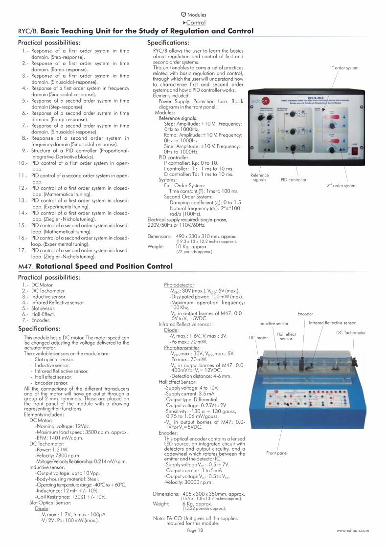
RYC/B. Basic Teaching Unit for the Study of Regulation and Control
1.- Response of a first order system in time domain. (Step-response).
2.- Response of a first order system in time domain. (Ramp-response).
3.- Response of a first order system in time domain. (Sinusoidal-response).
4.- Response of a first order system in frequency domain (Sinusoidal-response).
5.- Response of a second order system in time domain (Step-response).
6.- Response of a second order system in time domain. (Ramp-response).
7.- Response of a second order system in time domain. (Sinusoidal-response).
8.- Response of a second order system in frequency domain (Sinusoidal-response).
9.- Structure of a PID controller (Proportional- Integrative-Derivative blocks).
10.- PID control of a first order system in open- loop.
11.- PID control of a second order system in open- loop.
12.- PID control of a first order system in closed- loop. (Mathematical tuning).
13.- PID control of a first order system in closed- loop. (Experimental tuning)
14.- PID control of a first order system in closed- loop. (Ziegler -Nichols tuning).
15.- PID control of a second order system in closed- loop. (Mathematical tuning).
16.- PID control of a second order system in closed- loop. (Experimental tuning).
17.- PID control of a second order system in closed- loop. (Ziegler -Nichols tuning).
M47. Rotational Speed and Position Control
Practical possibilities:
www.edibon.comPage 18
1.- DC Motor 2.- DC Tachometer. 3.- Inductive sensor. 4.- Infrared Reflective sensor 5.- Slot sensor. 6.- Hall-Effect. 7.- Encoder.
This module has a DC motor. The motor speed can be changed adjusting the voltage delivered to the actuator motor.
The available sensors on the module are: - Slot optical sensor. - Inductive sensor. - Infrared Reflective sensor. - Hall effect sensor. - Encoder sensor. All the connections of the different transducers
and of the motor will have an outlet through a group of 2 mm. terminals. These are placed on the front panel of the module with a drawing representing their functions.
Elements included: DC Motor: -Nominal voltage: 12Vdc. -Maximum load speed: 3500 r.p.m. approx. -EFM: 1401 mV/r.p.m. DC Tachometer: -Power: 1.21W. -Velocity: 7800 r.p.m. -Voltage/Velocity Relationship: 0.214 mV/r.p.m. Inductive sensor: -Output voltage: up to 10 Vpp. -Body-housing material: Steel. -Operating temperature range: -40ºC to +60ºC. -Inductance: 12 mH +/- 10%. -Coil Resistance: 130 +/- 10%. Slot Optical Sensor: Diode: -V max.: 1.7V., Ir max.: 100A.F
-V : 2V.. Po: 100 mW (max.).r
Photodetector: -V : 30V (max.). V : 5V (max.).CEO ECO
-Dissipated power: 100 mW (max). -Maximum operation frequency:
100 Khz. -V in output bornes of M47: 0.0 - O
5V to V = 5VDC.S
Infrared Reflective sensor: Diode: -V max.: 1.6V., V max.: 3V.F r
-Po max.: 70 mW. Phototransmitter: -V max.: 30V., V max.: 5V.CEO ECO
-Po max.: 70 mW. -V in output bornes of M47: 0.0- O
400mV for V = 12VDC.S
-Detection distance: 4-6 mm. Hall Effect Sensor: -Supply voltage: 4 to 10V. -Supply current: 3.5 mA. -Output type: Differential. -Output voltage: 0.25V to 2V. -Sensitivity: -130 a + 130 gauss,
0.75 to 1.06 mV/gauss. - V in output bornes of M47: 0.0- O
1V for V =5VDC.S
Encoder: This optical encoder contains a lensed
LED source, an integrated circuit with detectors and output circuitry, and a codewheel which rotates between the emitter and the detector IC.
-Supply voltage V : -0.5 to 7V.CC
-Output current: -1 to 5 mA. -Output voltage V : -0.5 to V .O CC
-Velocity: 30000 r.p.m.
Dimensions: 405 x 300 x 350mm. approx. (15.9 x 11.8 x 13.7 inches approx.).
Weight: 6 Kg. approx. (13.22 pounds approx.).
Specifications:DC motor
Inductive sensor
Hall effect sensor
Encoder
Front panel
DC Tachometer
Infrared Reflective sensor
Specifications: RYC/B allows the user to learn the basics
about regulation and control of first and second order systems.
This unit enables to carry a set of practices related with basic regulation and control, through which the user will understand how to characterize first and second order systems and how a PID controller works.
Elements included: Power Supply. Protection fuse. Block
diagrams in the front panel. Modules: Reference signals: Step: Amplitude: 10 V. Frequency:
0Hz to 1000Hz. Ramp: Amplitude: 10 V. Frequency:
0Hz to 1000Hz. Sine: Amplitude: 10 V. Frequency:
0Hz to 1000Hz. PID controller: P controller: Kp: 0 to 10. I controller: Ti: 1 ms to 10 ms. D controller: Td: 1 ms to 10 ms. Systems: First Order System: Time constant (T): 1ms to 100 ms. Second Order System: Damping coefficient ): 0 to 1.5 Natural frequency ( ): 2**100 n
rad/s (100Hz).Electrical supply required: single-phase, 220V./50Hz or 110V./60Hz.
Dimensions: 490 x 330 x 310 mm. approx. (19.3 x 13 x 12.2 inches approx.).
Weight: 10 Kg. approx. (22 pounds approx.).
nd2 order system PID controller
Referencesignals
Note: FA-CO Unit gives all the supplies required for this module.
st1 order system
Microprocessors
2 Modules
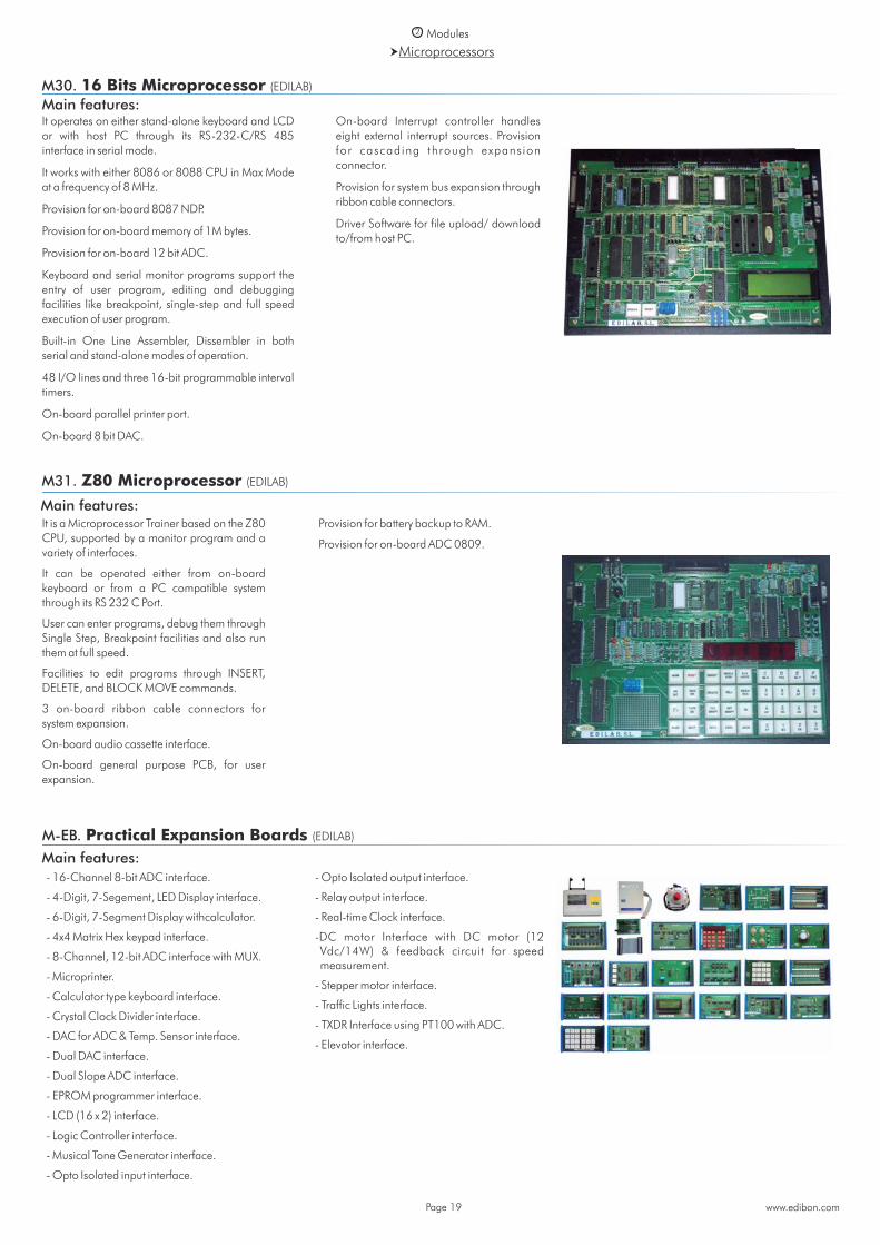
M30. 16 Bits Microprocessor (EDILAB)
Main features:It operates on either stand-alone keyboard and LCD or with host PC through its RS-232-C/RS 485 interface in serial mode.
It works with either 8086 or 8088 CPU in Max Mode at a frequency of 8 MHz.
Provision for on-board 8087 NDP.
Provision for on-board memory of 1M bytes.
Provision for on-board 12 bit ADC.
Keyboard and serial monitor programs support the entry of user program, editing and debugging facilities like breakpoint, single-step and full speed execution of user program.
Built-in One Line Assembler, Dissembler in both serial and stand-alone modes of operation.
48 I/O lines and three 16-bit programmable interval timers.
On-board parallel printer port.
On-board 8 bit DAC.
On-board Interrupt controller handles eight external interrupt sources. Provision for cascading through expansion connector.
Provision for system bus expansion through ribbon cable connectors.
Driver Software for file upload/ download to/from host PC.
Main features:
M31. Z80 Microprocessor (EDILAB)
It is a Microprocessor Trainer based on the Z80 CPU, supported by a monitor program and a variety of interfaces.
It can be operated either from on-board keyboard or from a PC compatible system through its RS 232 C Port.
User can enter programs, debug them through Single Step, Breakpoint facilities and also run them at full speed.
Facilities to edit programs through INSERT, DELETE, and BLOCK MOVE commands.
3 on-board ribbon cable connectors for system expansion.
On-board audio cassette interface.
On-board general purpose PCB, for user expansion.
Provision for battery backup to RAM.
Provision for on-board ADC 0809.
www.edibon.comPage 19
M-EB. Practical Expansion Boards (EDILAB)
- 16-Channel 8-bit ADC interface.
- 4-Digit, 7-Segement, LED Display interface.
- 6-Digit, 7-Segment Display withcalculator.
- 4x4 Matrix Hex keypad interface.
- 8-Channel, 12-bit ADC interface with MUX.
- Microprinter.
- Calculator type keyboard interface.
- Crystal Clock Divider interface.
- DAC for ADC & Temp. Sensor interface.
- Dual DAC interface.
- Dual Slope ADC interface.
- EPROM programmer interface.
- LCD (16 x 2) interface.
- Logic Controller interface.
- Musical Tone Generator interface.
- Opto Isolated input interface.
- Opto Isolated output interface.
- Relay output interface.
- Real-time Clock interface.
- DC motor Interface with DC motor (12 Vdc/14W) & feedback circuit for speed measurement.
- Stepper motor interface.
- Traffic Lights interface.
- TXDR Interface using PT100 with ADC.
- Elevator interface.
Main features:
2 ModulesMicroprocessors:(continuation)
M32. 8051 Microcontroller (EDILAB)
It operates on either in stand-alone mode using computer (PC) keyboard and LCD or with host PC through its RS-232-C/RS-485 interface in serial mode.
Line assembler and disassembler in both modes: stand-alone and serial modes.
On-board parallel printer port.
On-board 8 bit DAC.
Keyboard and serial monitor programs support the entry of user programs, editing and debugging facilities like breakpoints (128K),single stepping and full speed execution of user programs.
Total memory on-board is 128K bytes.
13 port lines of the MCU are brought out to the connector including INT1, RXD & TXD pins.
Buffered bus signals are available through ribbon cable connector for system expansion.
User friendly Windows, Linux and DOS driver software for file upload/download to/from host PC.
Main features:
www.edibon.comPage 20
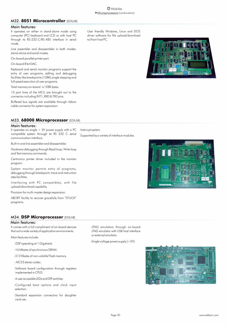
M33. 68000 Microprocessor (EDILAB)
M34. DSP Microprocessor (EDILAB)
It operates on single + 5V power supply with a PC compatible system through its RS 232 C serial communication interface.
Built-in one line assembler and disassembler.
Hardware debugging through Read loop, Write loop and Test memory commands.
Centronics printer driver included in the monitor program.
System monitor permits entry of programs, debugging through breakpoint, trace and instruction step facilities.
Interfacing with PC compatibles, with fi le upload/download capability.
Provision for multi-master design expansion.
ABORT facility to recover gracefully from “STUCK” programs.
Interrupt system.
Supported by a variety of interface modules.
It comes with a full compliment of on-board devices that suit a wide variety of application environments.
Main features include:
- DSP operating at 1 Gigahertz.
- 16 Mbytes of synchronous DRAM.
- 512 Kbytes of non-volatile Flash memory.
- AIC23 stereo codec.
- Software board configuration through registers implemented in CPLD.
-4 user accessible LEDs and DIP switches.
- Configured boot options and clock input selection.
- Standard expansion connectors for daughter card use.
- JTAG emulation through on-board JTAG emulator with USB host interface or external emulator.
- Single voltage power supply (+5V).
Main features:
Main features:

CAI. Computer Aided Instruction Software System3
Available Student/Module Softwares:
www.edibon.comPage 21
Basic Electronics concepts
M3/SOF. Semiconductors I.
M4/SOF. Semiconductors II.
M6/SOF. Oscillators.
M7/SOF. Operational Amplifiers.
M8/SOF. Filters.
M9/SOF. Power Electronics.
M60/SOF. Analog/Digital Converters.
M61/SOF. Digital/Analog Converters.
M99/SOF. Expansion Unit.
M99-6/SOF. Motors, Generators and Controls Unit.
Digital Electronics M10/SOF. Digital Systems & Converters. M11/SOF. Digital Electronics Fundamentals. M12/SOF. Basic Combinational Circuits. M13/SOF. Basic Sequential Circuits. M14/SOF. Optoelectronics. M41/SOF. Resistance Transducers.
Basic Electricity concepts M5/SOF. Power Supplies. M1/SOF. Direct Current (D.C.) Circuits. M2/SOF. Alternating Current (A.C.) Circuits. M16/SOF. Electric Networks. M17/SOF. Electromagnetism. M18/SOF. Three-phase Circuits.
Electronics Applications
M49/SOF. Applications of Temperature and Pressure.
M44/SOF. Applications of Light.
M45/SOF. Linear Position and Force.
M46/SOF. Environmental Measurements.
M48/SOF. Sounds Measurements.
Control
RYC/B/SOF. Study of Regulation and Control.
M47/SOF. Rotational Speed & Position Control.
With no physical connection between module and computer (PC), this complete software package consists on an Instructor Software (INS/SOF) totally integrated with the Student/Module Software (M../SOF). Both are interconnected so that the teacher knows at any moment what is the theoretical and practical knowledge of the students.
- M . . / S O F. C o m p u t e r A i d e d Instruction Softwares (Student/ Module Software).
It explains how to use the module, run the experiments and what to do at any moment.
Each module has its own Student Software.
- The options are presented by pull-down menu s and pop -up windows.
- Each Software contains: Theory: gives the student the
theoretical background for a total understanding of the studied subject.
Exercises: divided by thematic areas and chapters to check out t ha t t he t heo r y ha s been understood.
Guided Practices: presents several practices to be done with the module, showing how to per form the exerc i ses and practices.
Exams: set of questions to test the obtained knowledge.
-INS/SOF. Classroom Management Software (Instructor Software):
The Instructor can: Organize Students by Classes and
Groups. Create easily new entries or delete
them. Create data bases with student
information. Ana l y ze re su l t s and make
statistical comparisons. Generate and print reports. Detect student’s progress and
difficulties. ...and many other facilities.
The Instructor Software is the same for all the modules, and working in network configuration allows controlling all the students in the classroom.
InstructorSoftware
Module
Student/ModuleSoftware
+
Instructor Software
Student/Module Software
For more information see CAI catalogue. Click on the following link: www.edibon.com/products/catalogues/en/CAI.pdf
4 LIEBA/CAL. Computer Aided Learning Software (Results Calculation and Analysis)
www.edibon.comPage 22
Available Softwares:Basic Electronics concepts
M3/CAL. Semiconductors I.
M4/CAL. Semiconductors II.
M6/CAL. Oscillators.
M7/CAL. Operational Amplifiers.
M8/CAL. Filters.
M9/CAL. Power Electronics.
M60/CAL. Analog/Digital Converters.
M61/CAL. Digital/Analog Converters.
M99/CAL. Expansion Unit.
M99-6/CAL. Motors, Generators and Controls Unit.
Digital Electronics M10/CAL. Digital Systems & Converters. M11/CAL. Digital Electronics Fundamentals. M12/CAL. Basic Combinational Circuits. M13/CAL. Basic Sequential Circuits. M14/CAL. Optoelectronics. M41/CAL. Resistance Transducers.
Basic Electricity concepts M5/CAL. Power Supplies. M1/CAL. Direct Current (D.C.) Circuits. M2/CAL. Alternating Current (A.C.) Circuits. M16/CAL. Electric Networks. M17/CAL. Electromagnetism. M18/CAL. Three-phase Circuits.
Electronics Applications
M49/CAL. Applications of Temperature and Pressure.
M44/CAL. Applications of Light.
M45/CAL. Linear Position and Force.
M46/CAL. Environmental Measurements.
M48/CAL. Sounds Measurements.
Control
RYC/B/CAL. Study of Regulation and Control.
M47/CAL. Rotational Speed & Position Control.
For more information see CAL catalogue. Click on the following link:
www.edibon.com/products/catalogues/en/CAL.pdf
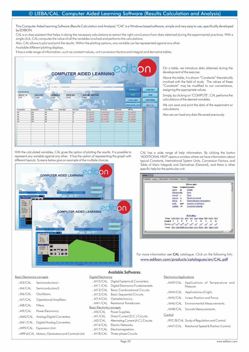
This Computer Aided Learning Software (Results Calculation and Analysis) “CAL” is a Windows based software, simple and very easy to use, specifically developed by EDIBON. CAL is a class assistant that helps in doing the necessary calculations to extract the right conclusions from data obtained during the experimental practices. With a single click, CAL computes the value of all the variables involved and performs the calculations.Also, CAL allows to plot and print the results. Within the plotting options, any variable can be represented against any other. Available different plotting displays.It has a wide range of information, such as constant values, unit conversion factors and integral and derivative tables.
On a table, we introduce data obtained during the development of the exercise.
Above this table, it is shown “Constants” theoretically involved with the field of study. The values of these “Constants” may be modified to our convenience, assigning the appropriate values.
Simply, by clicking on "COMPUTE", CAL performs the calculations of the desired variables.
We can save and print the data of the experiment or calculations.
Also we can load any data file saved previously.
With the calculated variables, CAL gives the option of plotting the results. It is possible to represent any variable against any other. It has the option of representing the graph with different layouts. Screens below give an example of the multiple choices.
CAL has a wide range of help information. By clicking the button "ADDITIONAL HELP" opens a window where we have information about typical Constants, International System Units, Conversion Factors, and Table of Main Integrals and Derivatives (General), and there is other specific help for the particular unit.
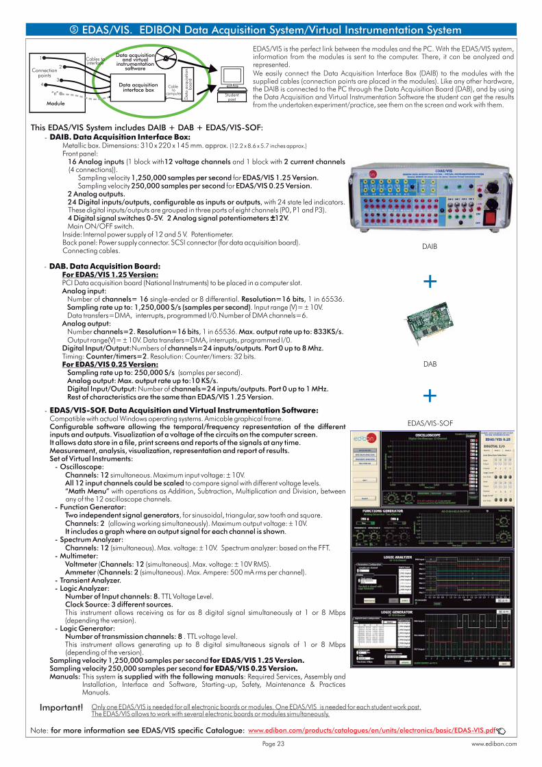
EDAS/VIS is the perfect link between the modules and the PC. With the EDAS/VIS system, information from the modules is sent to the computer. There, it can be analyzed and represented.We easily connect the Data Acquisition Interface Box (DAIB) to the modules with the supplied cables (connection points are placed in the modules). Like any other hardware, the DAIB is connected to the PC through the Data Acquisition Board (DAB), and by using the Data Acquisition and Virtual Instrumentation Software the student can get the results from the undertaken experiment/practice, see them on the screen and work with them.
- DAB. Data Acquisition Board: For EDAS/VIS 1.25 Version: PCI Data acquisition board (National Instruments) to be placed in a computer slot. Analog input: Number of channels= 16 single-ended or 8 differential. Resolution=16 bits, 1 in 65536.
Sampling rate up to: 1,250,000 S/s (samples per second). Input range (V)= 10V. Data transfers=DMA, interrupts, programmed I/0.Number of DMA channels=6. Analog output: Number channels=2. Resolution=16 bits, 1 in 65536. Max. output rate up to: 833KS/s. Output range(V)= 10V. Data transfers=DMA, interrupts, programmed I/0. Digital Input/Output:Numbers of channels=24 inputs/outputs. Port 0 up to 8 Mhz. Timing: Counter/timers=2. Resolution: Counter/timers: 32 bits. For EDAS/VIS 0.25 Version: Sampling rate up to: 250,000 S/s (samples per second). Analog output: Max. output rate up to:10 KS/s. Digital Input/Output: Number of channels=24 inputs/outputs. Port 0 up to 1 MHz. Rest of characteristics are the same than EDAS/VIS 1.25 Version.
5
- DAIB. Data Acquisition Interface Box: Metallic box. Dimensions: 310 x 220 x 145 mm. approx. (12.2 x 8.6 x 5.7 inches approx.) Front panel: 16 Analog inputs (1 block with12 voltage channels and 1 block with 2 current channels
(4 connections)). Sampling velocity 1,250,000 samples per second for EDAS/VIS 1.25 Version. Sampling velocity 250,000 samples per second for EDAS/VIS 0.25 Version. 2 Analog outputs. 24 Digital inputs/outputs, configurable as inputs or outputs, with 24 state led indicators.
These digital inputs/outputs are grouped in three ports of eight channels (P0, P1 and P3). 4 Digital signal switches 0-5V. 2 Analog signal potentiometers 12V. Main ON/OFF switch. Inside: Internal power supply of 12 and 5 V. Potentiometer. Back panel: Power supply connector. SCSI connector (for data acquisition board). Connecting cables.
- EDAS/VIS-SOF. Data Acquisition and Virtual Instrumentation Software: Compatible with actual Windows operating systems. Amicable graphical frame. Configurable software allowing the temporal/frequency representation of the different
inputs and outputs. Visualization of a voltage of the circuits on the computer screen. It allows data store in a file, print screens and reports of the signals at any time. Measurement, analysis, visualization, representation and report of results. Set of Virtual Instruments: - Oscilloscope: Channels: 12 simultaneous. Maximum input voltage: 10V. All 12 input channels could be scaled to compare signal with different voltage levels. “Math Menu” with operations as Addition, Subtraction, Multiplication and Division, between
any of the 12 oscilloscope channels. - Function Generator: Two independent signal generators, for sinusoidal, triangular, saw tooth and square. Channels: 2 (allowing working simultaneously). Maximum output voltage: 10V. It includes a graph where an output signal for each channel is shown. - Spectrum Analyzer: Channels: 12 (simultaneous). Max. voltage: 10V. Spectrum analyzer: based on the FFT. - Multimeter: Voltmeter (Channels: 12 (simultaneous). Max. voltage: 10V RMS). Ammeter (Channels: 2 (simultaneous). Max. Ampere: 500 mA rms per channel). - Transient Analyzer. - Logic Analyzer: Number of Input channels: 8. TTL Voltage Level. Clock Source: 3 different sources. This instrument allows receiving as far as 8 digital signal simultaneously at 1 or 8 Mbps
(depending the version). - Logic Generator: Number of transmission channels: 8 . TTL voltage level. This instrument allows generating up to 8 digital simultaneous signals of 1 or 8 Mbps
(depending of the version). Sampling velocity 1,250,000 samples per second for EDAS/VIS 1.25 Version. Sampling velocity 250,000 samples per second for EDAS/VIS 0.25 Version. Manuals: This system is supplied with the following manuals: Required Services, Assembly and
Installation, Interface and Software, Starting-up, Safety, Maintenance & Practices Manuals.
Only one EDAS/VIS is needed for all electronic boards or modules. One EDAS/VIS is needed for each student work post.The EDAS/VIS allows to work with several electronic boards or modules simultaneously.
This EDAS/VIS System includes DAIB + DAB + EDAS/VIS-SOF:
EDAS/VIS. EDIBON Data Acquisition System/Virtual Instrumentation System
Important!
Connectionpoints
Module
Studentpost
Data acquisition and virtual
instrumentationsoftware
1
2
34
“n”
Cables tointerface
Data acquisitioninterface box
Dat
a ac
quis
ition
boar
d
Cable to
computer
DAIB
DAB
EDAS/VIS-SOF
www.edibon.com/products/catalogues/en/units/electronics/basic/EDAS-VIS.pdfNote: for more information see EDAS/VIS specific Catalogue: fff
www.edibon.comPage 23
REQUIRED SERVICES
- Electrical power supply needed for FA-CO and EBC-100: single-phase, 220V/50Hz or 110V/60 Hz.
- For using EDAS/VIS, CAI and LIEBA/CAL a Computer (PC) is required.
Page 24
*Specifications subject to change without previous notice, due to the convenience of improvements of the product.
Issue: ED01/15Date: March/2015
REPRESENTATIVE:
C/ Del Agua, 14. Polígono Industrial San José de Valderas. 28918 LEGANÉS. (Madrid). SPAIN.Phone: 34-91-6199363 FAX: 34-91-6198647E-mail: [email protected] WEB site: www.edibon.com