Embed Size (px)
Citation preview

Liebert® Air-Cooled Fin/TubeCondensers
50 Hz and 60 Hz
Technical Design Manual

Technical Support Site
If you encounter any installation or operational issues with your product, check the pertinent section ofthis manual to see if the issue can be resolved by following outlined procedures. Visithttps://www.VertivCo.com/en-us/support/ for additional assistance.

TABLE OF CONTENTS
1 Introduction 5
1.1 Product Description and Features 5
1.2 Agency Listed 5
1.3 Location 6
1.4 Liebert Condenser Model Number Nomenclature 6
2 Standard Features 7
2.1 Standard Features—All Condensers 7
2.1.1 Condenser Coil 7
2.1.2 Housing 7
2.1.3 Propeller Fan 7
2.1.4 Fan Motor 7
2.1.5 Electrical Controls 7
3 Specific Condenser Types—Features 9
3.1 Head Pressure Control Types 9
3.1.1 Fan Speed 9
3.1.2 Variable Frequency Drive 9
3.1.3 Liebert Lee-Temp™ Refrigerant Control 9
3.2 Sound Level Options 9
3.2.1 Standard Condenser 9
3.2.2 Liebert Quiet-Line Condenser 10
3.3 Surge Protective Device—Optional 10
3.4 Typical System Configurations 10
4 Condenser Performance Data 11
5 Dimensions and Weights 15
5.1 Condenser Dimensions and Anchor Plan 15
5.2 Condenser Weights 19
6 Refrigerant Piping and Charge Planning 23
6.1 Refrigerant Piping Configurations 23
6.2 Refrigerant Charge Planning Values 28
6.3 Condenser Positioning guidelines 31
7 Electrical Data 35
7.1 Electrical Connections 40
7.2 Low Voltage Control Wiring 42
7.3 Low Voltage Monitoring Wiring—VFD Condensers Only 43
Appendices 45
Appendix A: Guide Specifications for Liebert Air-cooled Condensers with Direct-drive Propeller Fan 45
Vertiv | Liebert® Fin/Tube Condensers TechnicalDesignManual | 3

Vertiv | Liebert® Fin/Tube Condensers TechnicalDesignManual | 4
1 INTRODUCTION
1.1 Product Description and Features
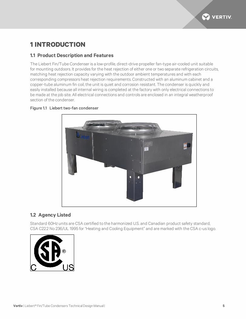
The Liebert Fin/Tube Condenser is a low-profile, direct-drive propeller fan-type air-cooled unit suitablefor mounting outdoors. It provides for the heat rejection of either one or two separate refrigeration circuits,matching heat rejection capacity varying with the outdoor ambient temperatures and with eachcorresponding compressors heat rejection requirements. Constructed with an aluminum cabinet and acopper-tube aluminum fin coil, the unit is quiet and corrosion resistant. The condenser is quickly andeasily installed because all internal wiring is completed at the factory with only electrical connections tobe made at the job site. All electrical connections and controls are enclosed in an integral weatherproofsection of the condenser.
Figure 1.1 Liebert two-fan condenser
1.2 Agency Listed
Standard 60Hz units are CSA certified to the harmonized U.S. and Canadian product safety standard,CSA C22.2 No 236/UL 1995 for “Heating and Cooling Equipment” and are marked with the CSA c-us logo.
Vertiv | Liebert® Fin/Tube Condensers TechnicalDesignManual | 5

1.3 Location
When considering installation locations, consider that these units reject heat into the atmosphere andshould be located in a clean air area, away from loose dirt and foreign matter that may clog the coil. Inaddition, condensers must not be located in the vicinity of steam, hot air or fume exhausts. Condensersshould be located no closer than 3 feet from a wall, obstruction or adjacent unit with no obstructions overthe unit. Install condensers in a level position to assure proper refrigerant flow and oil return. Condensersmust be installed in vertical airflow orientation to ensure NEMA 3R rating of electrical box. For roofinstallation, mount the condenser on suitable curbs or other supports in accordance with local codes.
Do not mount condensers in areas where normal unit operating sound levels might disturb the working orresidential environments of others.
Use caution when installing condensers below the indoor unit. Fan Speed and VFD condensers must notbe installed more than 15ft. (4.6m) below the indoor unit; Liebert Lee-Temp™ condensers should beinstalled above or at the same level as the indoor unit. Contact the factory for assistance in specifyingsub-cooling coils to each circuit to extend these limits.
1.4 Liebert Condenser Model Number Nomenclature
NOTE: Not all model/options/voltage combinations are available.
Vertiv | Liebert® Fin/Tube Condensers TechnicalDesignManual | 6

2 STANDARD FEATURES
2.1 Standard Features—All Condensers
Liebert condensers consist of condenser coil(s), housing, propeller fan(s) direct-driven by individual fanmotor(s), electrical controls and mounting legs. Liebert air-cooled condensers provide positive refrigeranthead pressure control to the Precision Cooling indoor unit by adjusting heat rejection capacity. Variousmethods are employed to match indoor unit type, minimum outdoor design ambient and maximum soundrequirements.
2.1.1 Condenser Coil
Liebert-manufactured coils are constructed of copper tubes in a staggered tube pattern. Tubes areexpanded into continuous, corrugated aluminum fins. The fins have full-depth fin collars completelycovering the copper tubes, which are connected to heavy wall Type “L” headers. Inlet coil connector tubespass through relieved holes in the tube sheet for maximum resistance to piping strain and vibration. Coilsare either single circuit or dual circuit, depending on the application. The hot-gas and liquid lines arespun shut at the factory and include a factory-installed Schrader valve. Coils are factory leak-tested at aminimum of 300 psig (2068kPag), dehydrated, then filled and sealed with a low pressure inert gas holdingcharge for shipment.
2.1.2 Housing
The condenser housing is fabricated from bright aluminum sheet and divided into individual fan sectionsby full width baffles. Structural support members, including coil support frame, motor and drive support,are galvanized steel for strength and corrosion resistance. Aluminum legs are provided for mounting unitfor vertical discharge and have rigging holes for hoisting the unit into position. The unit’s electrical panelis inside an integral NEMA 3R weatherproof section of the housing.
2.1.3 Propeller Fan
Aluminum propeller fan blades are secured to a corrosion-protected steel hub. Fan guards are heavygauge, close-meshed steel wire with corrosion-resistant polyester paint finish rated to pass a 1000-hoursalt spray test. Fans are secured to the fan motor shaft by a keyed hub and dual setscrews. Fan diameteris 26" (660mm) or less. The fans are factory-balanced and run before shipment.
2.1.4 Fan Motor
The condenser’s fan motor is a continuous air-over design equipped with rain shield and permanentlysealed bearing. Die-formed, galvanized steel supports are used for rigid mounting of the motor.
2.1.5 Electrical Controls
Electrical controls, overload protection devices and service connection terminals are factory-wired insidethe integral electrical panel section of the housing. A locking disconnect switch is factory-mounted andwired to the electrical panel and controlled via an externally mounted locking door handle. An indoor unitinterlock circuit enables condenser operation whenever indoor unit compressors are active. Only supplywiring and indoor unit interlock wiring are required at condenser installation.
Vertiv | Liebert® Fin/Tube Condensers TechnicalDesignManual | 7

Vertiv | Liebert® Fin/Tube Condensers TechnicalDesignManual | 8
This page intentionally left blank.
3 SPECIFIC CONDENSER TYPES—FEATURES
3.1 Head Pressure Control Types
3.1.1 Fan Speed
Fan speed control utilizes a wave-chopper control to vary the air volume over the condenser coil, based onrefrigerant head pressure. The fan motor next to the electrical panel (two fans on 6-fan and 8-fan models)is a single-phase, permanent split capacitor motor with motor speed adjusted in response to refrigerantpressure. The balance of fans on multi-fan units cycle on ambient thermostats. The control systemprovides refrigerant head pressure control for outdoor ambients as low as -20°F (-28.9 °C).
3.1.2 Variable Frequency Drive
VFD condenser control system utilizes a variable frequency drive, inverter duty fan motor operating from0% to 100% motor RPM based on head pressure, sensed by refrigerant pressure transducers. VFD,ambient-temperature thermostat(s), motor overload protection and electrical control circuit are factory-wired in the integral control panel. VFD controls the fan adjacent to the connection end of the condenserand remains energized with active compressor operation. The balance of fans on multi-fan units cycle onambient thermostats. This system provides refrigerant head pressure control for outdoor ambients as lowas 0°F (–17.8°C) as standard and, with optional, low-ambient VFD heater kit, will start/operate as low as-20°F (-28.9°C).
3.1.3 Liebert Lee-Temp™ Refrigerant Control
The Liebert Lee-Temp head pressure control system is designed to maintain proper operating headpressures in outdoor temperatures down to -30°F (-34.4°C). The condensers utilize head pressure controlvalves, extra refrigerant and insulated refrigerant receivers with heater pads. It works by flooding thecondenser coil with liquid refrigerant to a level that balances the system condensing requirements withthe condenser coil surface available to reject the system heat. During the summer, the system requiresthe entire condenser coil surface for heat rejection and most of the refrigerant is stored in a receiver. Inthe winter, the same amount of heat can be rejected by only a fraction of the coil surface. As headpressure begins to fall, the control valve restricts the flow of liquid refrigerant exiting from the condenser.This extra liquid refrigerant reduces the effective condenser surface area available for heat transfer. Thehead pressure control valve also bypasses hot gas into the receiver to warm the liquid and maintain liquidpressure for proper operation of the expansion valve. Condenser fan controls are either fan cycling onambient temperature or constant on. Liebert Lee-Temp control is required for Liebert Quiet-Line™condensers.
3.2 Sound Level Options
3.2.1 Standard Condenser
All fan speed and VFD condensers are standard condensers with moderate operating sound levels.Liebert Lee-Temp condensers with standard-size coils matching fan speed and VFD coil sizes arestandard sound level condensers.
Vertiv | Liebert® Fin/Tube Condensers TechnicalDesignManual | 9

3.2.2 Liebert Quiet-Line Condenser
Liebert Quiet-Line condensers can help your facility meet the strictest noise codes and do so at less costthan traditional condensers with acoustical shielding. Liebert Quiet-Line condensers utilize the samereliable construction features of the standard condensers and have oversized coils and slower speed fanmotors which yield the required heat rejection needed at significantly lower sound levels. Liebert Lee-Temp control is required for Liebert Quiet-Line Condensers.
3.3 Surge Protective Device—Optional
A surge protective device (SPD) is standard in the VFD condenser models only. Surge protection isnecessary because rooftop voltage supply often is not conditioned the same as the voltage supply insidea data center. The SPD is designed to protect sensitive electronic condenser components from highvoltage transients, up to 25kVA/phase.
An illuminated green LED indicates power supply is On and panel status is OK. An illuminated red LEDindicates conditions require service and the SPD may require replacement to restore surge protection tothe condenser.
3.4 Typical System Configurations
Figure 6.10 on page 34 shows a single refrigeration circuit diagram, displaying the indoor air conditioningunit, the outdoor condenser (VFD, Fan Speed Control or Liebert Lee-Temp™) and field-suppliedinterconnection piping.
Vertiv | Liebert® Fin/Tube Condensers TechnicalDesignManual | 10
4 CONDENSER PERFORMANCE DATA
Model#
TotalHeat Rejection, kBtuh (kW)R-407C Fans Direct DriveSound
Power
LwA
Sound
Pressure
dBA*30°F
(16.7°C)TD
25°F
(13.9°C)TD
20°F
(11.1°C)TD
15°F
(8.3°C)TDQty Diam. HP CFM
Standard 90°F DB 95°F DB 100°F DB 105°F DB
083 102 (29.9) 82 (24.0) 63 (18.2) 43 (12.5) 1 26 3/4 5900 86.7 72.5
104 128 (37.3) 104 (30.4) 81 (23.5) 57 (16.7) 1 26 3/4 5500 86.6 72.5
165 208 (60.6) 167 (48.7) 127 (37.0) 87 (25.4) 2 26 3/4 11800 90.3 75.5
205 290 (84.7) 238 (69.5) 186 (54.3) 134 (39.1) 2 26 3/4 10300 91.0 75.5
251 301 (87.9) 243 (70.9) 185 (54.1) 129 (37.5) 3 26 3/4 17950 94.0 77.3
308 380 (110.9) 308 (89.9) 238 (69.3) 168 (49.0) 3 26 3/4 16650 93.8 77.3
415 601 (175.3) 491 (143.3) 383 (111.7) 278 (81.0) 4 26 3/4 20650 94.4 78.5
510 640 (186.6) 530 (154.7) 421 (122.9) 315 (91.8) 4 26 3/4 18200 94.4 78.5
616 760 (221.6) 619 (180.4) 475 (138.6) 336 (98.0) 6 26 3/4 33300 96.8 80.3
830 1200 (350.0) 983 (286.6) 765 (223.0) 555 (161.9) 8 26 3/4 41300 97.4 81.5
1010 1280 (373.3) 1061 (309.4) 846 (246.7) 627 (182.8) 8 26 3/4 36400 97.4 81.5
Liebert Quiet-Line™
063 70 (20.5) 58 (16.9) 46 (13.3) 33 (9.7) 1 26 1/4 2425 68.9 56.5
119 123 (36.0) 100 (29.1) 77 (22.6) 55 (16.2) 2 26 1/4 5250 72.6 59.5
127 141 (41.0) 116 (33.7) 90 (26.4) 66 (19.2) 2 26 1/4 4850 72.6 59.5
143 148 (43.2) 123 (35.8) 98 (28.6) 73 (21.3) 2 26 1/4 4250 72.6 59.5
214 232 (67.5) 193 (56.1) 154 (45.0) 116 (33.9) 3 26 1/4 6400 74.8 61.3
286 312 (90.9) 260 (75.7) 209 (60.9 157 (45.8) 4 26 1/4 8275 76.2 62.5
409 444 (129.4) 368 (107.2) 291 (84.8) 219 (63.8) 6 26 1/4 13750 78.4 64.3
572 623 (181.8) 519 (151.4) 417 (121.5) 312 (90.9) 8 26 1/4 17050 79.9 65.5
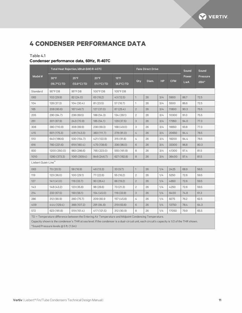
TD = Temperature difference between the Entering Air Temperature and Midpoint Condensing Temperature.
Capacity shown is the condenser’s THR at sea level. If the condenser is a dual-circuit unit, each circuit’s capacity is 1/2 of the THR shown.
*Sound Pressure levels @ 5 ft. (1.5m)
Table 4.1Condenser performance data, 60Hz, R-407C
Vertiv | Liebert® Fin/Tube Condensers TechnicalDesignManual | 11

Model#
TotalHeat Rejection, kW (kBtuh)R-410A Fans Direct DriveSound
Power
LwA
Sound
Pressure
dBA*30°F
(16.7°C)TD
25°F
(13.9°C)TD
20°F
(11.1°C)TD
15°F
(8.3°C)TDQty Diam. HP CFM
Standard 90°F DB 95°F DB 100°F DB 105°F DB
28K 31.6 (108) 26.4 (90) 20.5 (70) 15.0 (51) 1 26 3/4 5775 86.6 72.5
60K 74.2 (253) 60.4 (206) 46.8 (160) 34.0 (116) 2 26 3/4 11550 91.0 75.5
90K 118.6 (405) 97.2 (332) 76.0 (259) 55.0 (188) 3 26 3/4 17300 93.8 77.3
R-410A condensers are available only in 60 Hz.
TD = Temperature Difference between the Entering Air Temperature and Midpoint Condensing Temperature.
Capacity shown is the condenser’s THR at sea level. If the condenser is a dual-circuit unit, each circuit’s capacity is 1/2 of the THR shown.
*Sound Pressure levels @ 5 ft. (1.5m)
Table 4.2Condenser performance data, 60Hz, R-410A
Model#
TotalHeat Rejection, kBtuh (kW)R-407C Fans Direct Drive
30°F
(16.7°C)TD
25°F
(13.9°C)TD
20°F
(11.1°C)TD
15°F
(8.3°C)TDQty Diam. Hp CFM
Sound
Power
LwA
Sound
Pressure
dBA*
Standard 90°F DB 95°F DB 100°F DB 105°F DB
083 91 (26.6) 73 (21.4) 56 (16.3) 39 (11.3) 1 26 3/4 4900 81.7 68.3
104 112 (32.7) 92 (26.7) 71 (20.7) 51 (14.8) 1 26 3/4 4575 82.5 69.1
165 185 (54.0) 149 (43.5) 114 (33.2) 79 (23.0) 2 26 3/4 9800 85.9 71.8
205 251 (73.2) 206 (60.0) 161 (47.1) 118 (34.4) 2 26 3/4 8475 87.2 70.6
251 270 (78.8) 218 (63.6) 167 (48.7) 117 (34.1) 3 26 3/4 14900 89.4 73.5
308 333 (97.1) 271 (79.1) 210 (61.3) 149 (43.5) 3 26 3/4 13700 89.4 73.7
415 516 (150.4) 424 (123.8) 332 (96.9) 242 (70.5) 4 26 3/4 16950 91.0 75.7
510 542 (158.1) 450 (131.2) 360 (104.9) 269 (78.4) 4 26 3/4 14900 91.0 75.7
616 667 (194.5) 543 (158.4) 420 (122.6) 299 (87.2) 6 26 3/4 27450 92.4 76.7
830 1031 (300.8) 849 (247.5) 665 (194.0) 484 (141.3) 8 26 3/4 33900 94.0 78.7
1010 1085 (316.5) 900 (262.4) 721 (210.2) 538 (156.8) 8 26 3/4 29800 94.0 78.7
Table 4.3Condenser performance data, 50Hz, R-407C
Vertiv | Liebert® Fin/Tube Condensers TechnicalDesignManual | 12

Model#
TotalHeat Rejection, kBtuh (kW)R-407C Fans Direct Drive
30°F
(16.7°C)TD
25°F
(13.9°C)TD
20°F
(11.1°C)TD
15°F
(8.3°C)TDQty Diam. Hp CFM
Sound
Power
LwA
Sound
Pressure
dBA*
Liebert Quiet-Line™
063 60 (17.5) 50 (14.5) 39 (11.4) 29 (8.4) 1 26 1/4 2000 65.6 53.2
119 108 (31.4) 87 (25.5) 68 (19.7) 50 (14.6) 2 26 1/4 4350 69.3 56.2
127 121 (35.2) 99 (28.9) 78 (22.7) 57 (16.5) 2 26 1/4 4000 69.3 56.2
143 124 (36.2) 104 (30.2) 83 (24.1) 61 (17.9) 2 26 1/4 3475 69.3 56.2
214 193 (56.2) 161 (47.0) 131 (38.1) 100 (29.1) 3 26 1/4 5225 71.5 58.0
286 258 (75.3) 216 (62.9) 174 (50.8) 132 (38.5) 4 26 1/4 6750 72.9 59.2
409 378 (110.3) 312 (91.1) 249 (72.7) 188 (54.9) 6 26 1/4 11250 75.1 61.0
572 472 (137.8) 392 (114.2) 310 (90.5) 229 (66.8) 8 26 1/4 13900 76.6 62.2
R-410A condensers are available only in 60 Hz.
TD = Temperature Difference between the Entering Air Temperature and Midpoint Condensing Temperature.
*Sound Pressure levels at 5ft. (1.5m).
Table 4.3 Condenser performance data, 50Hz, R-407C (continued)
Vertiv | Liebert® Fin/Tube Condensers TechnicalDesignManual | 13

Vertiv | Liebert® Fin/Tube Condensers TechnicalDesignManual | 14
This page intentionally left blank.

5 DIMENSIONS AND WEIGHTS
5.1 Condenser Dimensions and Anchor Plan
Figure 5.1 Condenser planning dimensional data—1-fan and 2-fan units
Vertiv | Liebert® Fin/Tube Condensers TechnicalDesignManual | 15

Figure 5.2 Condenser planning dimensional data—3-fan and 4-fan units
Vertiv | Liebert® Fin/Tube Condensers TechnicalDesignManual | 16

Figure 5.3 Condenser planning dimensional data—6- and 8-fan units
Vertiv | Liebert® Fin/Tube Condensers TechnicalDesignManual | 17

Figure 5.4 Typical fin/tube condenser footprint—dimensions
Vertiv | Liebert® Fin/Tube Condensers TechnicalDesignManual | 18

5.2 Condenser Weights
ModelNo.of Fans
Unitdry weightlb. (kg)
Domestic Packaging Export Packaging
ShippingWeight lb. (kg)
Dimensions (LxWxH)in. (mm)
Volumeft3 (m3)
ShippingWeight lb. (kg)
Dimensions (LxWxH)in. (mm)
Volumeft3 (m3)
Standard Models
0831
295 (134)450 (204)
62 x36 x63
(157 x91 x160)81 (2.3)
557 (253) 63 x 37 x 64
(160 x 94 x 163)86 (2.5)
104 315 (143) 470 (213) 577 (262)
1652
425 (193) 682 (309) 102 x36 x63
(259 x91 x160)
134 (3.8) 839 (381) 103 x 37 x 64
(262 x 94 x 163)
141 (4.0)
205 495 (225) 752 (341) 909 (412)
251
3
500 (227) 859 (390)142 x36 x63
(361 x91 x160)
186 (5.3)
1047 (475)
143 x 37 x 64
(363 x 94 x 163)
196 (5.6)
308 670 (304)1029 (467) 1217 (552)
415
4
840 (381)1301 (590)
182 x36 x63
(462 x91 x160)
239 (6.7)
1558 (707)
183 x 37 x 64
(465 x 94 x 64)
251 (7.0)
510 1190 (540)1651 (749) 1908 (865)
616 6 1380 (626)1823 (827) 142 x36 x94
(361 x91 x239)
278 (7.9) 2105 (955) 143 x 37 x 95
(363 x 94 x 241)291 (8.2)
830
8
1750 (794)2315
(1050) 182 x36 x94
(462 x91 x239)
356
(10.0)
2704
(1227) 183 x 37 x 95
(465 x 94 x 241)
372
(10.5)1010 2640 (1197)
3205
(1454)
3594
(1630)
Liebert Quiet-Line Models
063 1 315 (143) 470 (213)62 x36 x63
(157 x91 x160)81 (2.3) 577 (262)
63 x 37 x 64
(160 x 94 x 163)86 (2.5)
119 2 425 (193) 682 (309)102 x36 x63
(259 x91 x160)
134 (3.8)839 (301)
103 x 37 x 64
(262 x 94 x 163)
141 (4.0)
Table 5.1Air-cooled Condenser Dry and Shipping Weights
Vertiv | Liebert® Fin/Tube Condensers TechnicalDesignManual | 19

ModelNo.of Fans
Unitdry weightlb. (kg)
Domestic Packaging Export Packaging
ShippingWeight lb. (kg)
Dimensions (LxWxH)in. (mm)
Volumeft3 (m3)
ShippingWeight lb. (kg)
Dimensions (LxWxH)in. (mm)
Volumeft3 (m3)
127 495 (225) 752 (341) 909 (412)
143 515 (234) 772 (350) 929 (421)
214 3 840 (381)1199 (544) 142 x36 x63
(361 x91 x160)
186 (5.3) 1387 (629) 143 x 37 x 64
(363 x 94 x 163)
196 (5.6)
286 4 1105 (501)1566 (710) 182 x36 x63
(462 x91 x160)
239 (6.7) 1823 (827) 183 x 37 x 64
(465 x 94 x 64)
251 (7.0)
409 6 1380 (626)1823 (827) 142 x36 x94
(361 x91 x239)
278 (7.9) 2105 (955) 143 x 37 x 95
(363 x 94 x 241)291 (8.2)
572 8 2430 (1102)2995
(1359)
182 x36 x94
(462 x91 x239)
356
(10.0)
3384
(1535)
183 x 37 x 95
(465 x 94 x 241)
372
(10.5)
R-410A Models
28K 1 325 (147) 480 (218)62 x36 x63
(157 x91 x160)81 (2.3) 587 (266)
63 x 37 x 64
(160 x 94 x 163)86 (2.5)
60K 2 475 (215) 732 (332)102 x36 x63
(259 x91 x160)
134 (3.8) 889 (403) 103 x 37 x 64
(262 x 94 x 163)
141 (4.0)
90K 3 675 (306)1034 (469) 142 x36 x63
(361 x91 x160)
186 (5.3) 1222 (554) 143 x 37 x 64
(363 x 94 x 163)
196 (5.6)
Table 5.1 Air-cooled Condenser Dry and Shipping Weights (continued)
Vertiv | Liebert® Fin/Tube Condensers TechnicalDesignManual | 20
Condenser
Model#
Receiver
Part #
Receivers
per
Condenser
Weight per
Receiver
lb. (kg)
Standard Models
DCSL083 1C19982P1
1
100 (45)
DCSL104 1C19982P1 100 (45)
DCSL165 W-0050 125 (57)
DCSL205 W-0050 125 (57)
DCSL251 W-0050 125 (57)
DCSL308 W-0060 145 (66)
DCSL415 185011P1 260 (118)
DCSL616 W-04101 200 (91)
DCSL616 179701P12 424 (192)
DCDL104 1C19982P1
2
100 (45)
DCDL165 1C19982P1 100 (45)
DCDL205 W-0050 125 (57)
DCDL251 1C19982P1 100 (45)
DCDL308 W-0050 125 (57)
DCDL415 W-0060 145 (66)
DCDL510 W-0410 200 (91)
DCDL616 W-0060 145 (66)
DCDL830 185011P1 260 (118)
Liebert Quiet-Line™ Models
DCSL063 1C19982P1
1
100 (45)
DCST119 W-0050 125 (57)
DCSL127 W-0050 125 (57)
DCSL143 W-0060 145 (66)
DCST214 W-0410 200 (91)
DCST286 W-0410 200 (91)
DCDL119 1C19982P12
100 (45)
DCDL127 1C19982P1 100 (45)
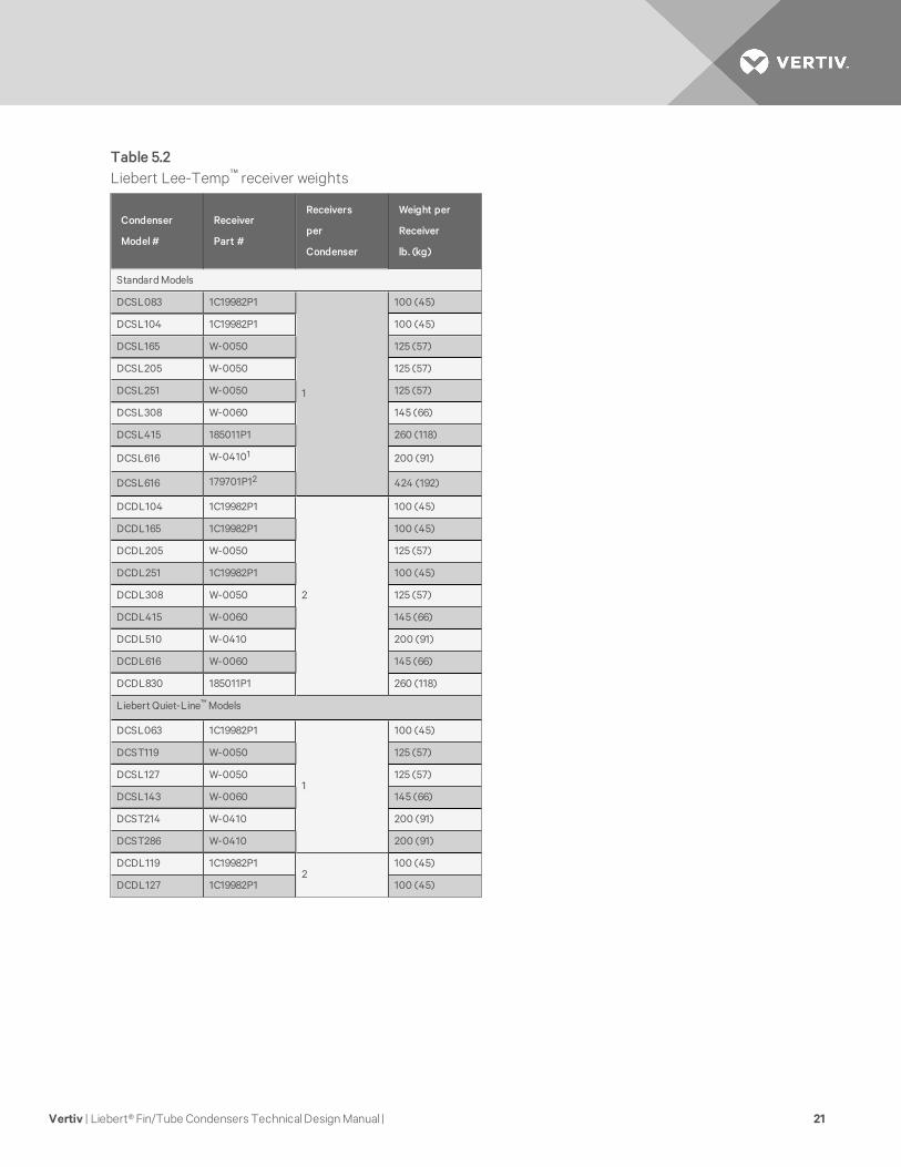
Table 5.2Liebert Lee-Temp™ receiver weights
Vertiv | Liebert® Fin/Tube Condensers TechnicalDesignManual | 21

Condenser
Model#
Receiver
Part #
Receivers
per
Condenser
Weight per
Receiver
lb. (kg)
DCDL143 W-0050 125 (57)
DCDT214 W-0050 125 (57)
DCDL286 W-0060 145 (66)
DCDT409 W-0410 200 (91)
DCDT572 W-0410 200 (91)
R-410A Models
DCSL28K 195315P1
1
125 (57)
DCSL60K 195316P1 145 (66)
DCSL90K 196702P1 200 (91)
1. Match-up for 35 to 105°F (2 to 41°C) design temperature range.
2.0Match-up for -30 to 105°F (-34 to 41°C) design temperature range.
Table 5.2 Liebert Lee-Temp™ receiver weights (con-tinued)
Vertiv | Liebert® Fin/Tube Condensers TechnicalDesignManual | 22

6 REFRIGERANT PIPING AND CHARGE PLANNING
6.1 Refrigerant Piping Configurations
Figure 6.1 Single-circuit piping, VFD and Fan Speed Control, 1-4 fan condensers
Condenser Piping Connection Sizes, CU. OD.
ModelNumberEnteringHot-gas Line,in.
ReturningLiquid Line, in.
TCSV28K1-1/8 7/8
TCSV60K
DCSF083, TCSV083 7/8 5/8
TCSV90K
1-1/8
7/8
DSCF104, TCSV104 5/8
DCSF165, TCSV165
7/8DCSF205, TCSV205
DCSF251, TCSV251
DCSF308, TCSV308 1-5/81-1/8
DCSF415 1-3/8
DCSF510 2-1/8 1-5/8
Vertiv | Liebert® Fin/Tube Condensers TechnicalDesignManual | 23

Figure 6.2 Single-circuit piping, Liebert Lee-Temp™ and Liebert Quiet-Line™ 1-4 fan condensers
Condenser Piping Connection Sizes
ModelNumberCondenserType
Condenser Connections ODS
Lee-TempReceiver
Lee-Temp Connections IDS
Hot-gas Line, in.Liquid Line,in.
Hot-gasTee, in.
Liq to L-TValve, in.
ReceiverOut, in.
DCSL28K
Standard
1-1/8 7/8195315P1
1-1/8 5/8 7/8DCSL60K 195316P1
DCSL083 7/8 5/8 1C19982P1
1-1/8 7/8 5/8DCSL90K
1-1/8
7/8 196702P1
DCSL104 5/8 1C19982P1
DCSL165
7/8W-0050
1-3/8 1-1/8 7/8
DCSL205
DCSL251
DCSL308 1-5/81-1/8
DCSL415 1-3/8 185011P1
Vertiv | Liebert® Fin/Tube Condensers TechnicalDesignManual | 24

Condenser Piping Connection Sizes
ModelNumberCondenserType
Condenser Connections ODS
Lee-TempReceiver
Lee-Temp Connections IDS
Hot-gas Line, in.Liquid Line,in.
Hot-gasTee, in.
Liq to L-TValve, in.
ReceiverOut, in.
DCSL063
Quiet-Line
1-1/8
5/8 1C19982P1 1-1/8 7/8 5/8
DCST119
7/8W-0050
1-3/8 1-1/8 7/8
DCSL127
DCSL143 W-0060
DCST214 1-5/81-1/8 W-0410
DCST286 2-1/8
Figure 6.3 Dual-circuit piping, VFD and Fan Speed Control, 1-4 fan condensers
Vertiv | Liebert® Fin/Tube Condensers TechnicalDesignManual | 25

Condenser Piping Connection Sizes, CU. OD. (2 per unit)
ModelNumberEnteringHot-gas Line,in.
ReturningLiquid Line, in.
DCDF1047/8
1/2
DCDF165, TCDF165 5/8
DCDF205, TCDV2051-1/8 7/8
DCDF251, TCDV251
DCDF308, TCDV3081-3/8
1-1/8DCDF415, TCDV415
DCDF510, TCDV510 1-5/8
Figure 6.4 Dual-circuit piping, Liebert Lee-Temp™ and Liebert Quiet-Line™ 1-4 fan condensers
Vertiv | Liebert® Fin/Tube Condensers TechnicalDesignManual | 26

ModelNumberCondenserType
Condenser Connections ODS (2 perunit)
Lee-TempReceiver
Lee-Temp Connections IDS (2 per unit)
Hot-gas Line, in.Liquid Line,in.
Hot-gasTee, in.
Liq to L-TValve, in.
ReceiverOut, in.
DCDL104
Standard
7/81/2
(2) 1C19982P1 1-1/8 7/8 5/8DCDL165 5/8
DCDL2051-1/8 7/8
(2) W-0050 1-3/8 1-1/8 7/8
DCDL251 (2) 1C19982P1 1-1/8 7/8 5/8
DCDL3081-3/8
1-1/8
(2) W-0050
1-3/8 1-1/8 7/8DCDL415 (2) W-0060
DCDL510 1-5/8 (2) W-0410
DCDL119
Quiet-Line
7/8 5/8(2) 1C19982P1 1-1/8 7/8 5/8
DCDL127
1-1/8 7/8DCDL143
(2) W-00501-3/8 1-1/8 7/8DCDT214
DCDL286 (2) W-0060
Figure 6.5 Dual-circuit piping, Fan Speed Control, 6- and 8-fan condensers
Vertiv | Liebert® Fin/Tube Condensers TechnicalDesignManual | 27

ModelNumberNumberof Fans
Connection Sizes, ODS (2 per unit)
EnteringHot-gas Line,in.
ReturningLiquid Line, in.
DCDF616 6 1-5/81-1/8
DCDF8308
1-3/8
DCDF1010 2-1/8 1-5/8
Figure 6.6 Dual-circuit piping, Liebert Lee-Temp and Liebert Quiet-Line 6- and 8-fan condensers
ModelNumber
CondenserType
FanQty.
Condenser Connections ODS (2per unit)
Lee-TempReceiver
Lee-Temp Connections IDS (2 per unit)
Hot-gas Line,in.
Liquid Line,in.
Hot-gasTee, in.
Liq to L-TValve, in.
ReceiverOut, in.
DCDL616Standard
6 1-5/8
1-1/8
(2) W-0060
1-3/8 1-1/8 7/8DCDL830 8 1-3/8 (2) 185011P1
DCDT409Quiet-Line
6 1-5/8(2) W-0410
DCDT572 8 2-1/8
6.2 Refrigerant Charge Planning Values
Planning for the refrigerant requirements of the completed system is the addition of the charges fromIndoor Unit, Condenser (including Liebert Lee-Temp™ receiver, if used) and the interconnecting piping.Table 6.1 on the facing page,Table 6.3 on page 30,Table 6.2 on page 30 andTable 6.4 on page 30 andprovide the approximate charge required for the condensers and the interconnecting piping. Consultindoor unit manuals for indoor unit charge requirements.
Vertiv | Liebert® Fin/Tube Condensers TechnicalDesignManual | 28

These values can be used for obtaining adequate refrigerant for the system, but should not be used forfinal charging. Consult indoor unit manual for charging procedures.
Standard
Condenser
Models
Approximate R-22 Refrigerant Needed Approximate R-407C Refrigerant Needed
Single Circuit
lb (kg)
Dual Circuit
lb/circuit (kg/circuit)
Single Circuit
lb (kg)
Dual Circuit
lb/circuit (kg/circuit)
FSC or
VFD
Lee-Temp
(includes
receiver)
FSC or
VFD
Lee-Temp
(includes
receiver)
FSC or
VFD
Lee-Temp
(includes
receiver)
FSC or
VFD
Lee-Temp
(includes
receiver)
083 5 (2.3) 27 (12.3) 3 (1.4) NA 5 (2.3) 26 (11.8) 3 (1.4) NA
104 8 (3.6) 39 (17.7) 7 (3.2) 21 (9.5) 8 (3.6) 37 (16.8) 7 (3.2) 20 (9.0)
165 15 (6.8) 53 (24.0) 5 (2.3) 27 (12.3) 15 (6.8) 50 (22.7) 5 (2.3) 26 (11.8)
205 20 (9.1) 76 (34.5) 7 (3.2) 56 (25.3) 19 (8.6) 72 (32.7) 7 (3.2) 54 (24.4)
251 19 (8.6) 75 (34.0) 10 (4.6) 38 (17.2) 18 (8.2) 71 (32.2) 10 (4.6) 36 (16.3)
308 29 (13.2) 113 (51.3) 11 (5.0) 58 (26.3) 28 (12.7) 107 (48.5) 11 (5.0) 55 (24.9)
415 54 (24.5) 210 (95.0) 25 (11.3) 107 (48.4) 51 (23.1) 200 (90.8) 24 (10.9) 102 (46.2)
510 72 (32.7) N/A 30 (13.6) 149 (67.6) 68 (30.8) N/A 29 (13.2) 142 (64.4)
616 N/A N/A 27 (12.3) 113 (51.3) N/ASee
Table 6.2 onthe next page
26 (11.8) 108 (49.0)
830 N/A N/A 53 (24) 210 (95.1) N/A N/A 51 (23.1) 200 (90.8)
1010 N/A N/A 60 (27.2) 154 (69.9) N/A N/A 57 (25.9) 147 (66.7)
Liebert Quiet-Line™ Condenser Models
063 N/A 39 (17.7) N/A NA N/A 37 (16.8) N/A NA
119 N/A 50 (22.7) N/A 27 (12.3) N/A 48 (21.8) N/A 26 (11.8)
127 N/A 76 (34.5) N/A 38 (17.2) N/A 72 (32.6) N/A 36 (16.3)
143 N/A 126 (57.2) N/A 64 (29.0) N/A 120 (54.5) N/A 61 (27.7)
214 N/A 161 (73.0) N/A 81 (36.7) N/A 153 (69.4) N/A 77 (34.9)
286 N/A 196 (88.9) N/A 125 (56.7) N/A 186 (84.4) N/A 119 (54.0)
409 N/A N/A N/A 152 (68.9) N/A N/A N/A 148 (67.2)
572 N/A N/A N/A 196 (88.9) N/A N/A N/A 186 (84.4)
Table 6.1R-22 and R-407C refrigerant required, approximate
Vertiv | Liebert® Fin/Tube Condensers TechnicalDesignManual | 29

Model#Liebert Lee-Temp
Receiver
Receiver Tank
Length, in. (mm)
Refrigerant Per Circuit
(inc. receiver),
lb. (kg)
DCSL616W-04101 48 (1219) 164 (75)
179701P12 96 (2438) 254 (115.2)
1. Match-up for 35 to 105°F (2 to 41°C) design temperature range.
2. Match-up for -30 to 105°F (-34 to 41°C) design temperature range.
Table 6.2R-407C refrigerant required for DCSL616 condensersfor Liebert XDC™, approximate
Single-Circuit
ModelVFD, lb (kg)
Liebert Lee-Temp™
(inc. receiver), lb (kg)
28K 7 (3.2) 41 (18.6)
60K 16 (7.3) 75 (34.0)
90K 25 (11.3) 109 (49.4)
Table 6.3R-410A refrigerant required, approximate
Line Size,
O.D., in.
R-407C (R-22), lb/100 ft. (kg/30m) R-410A, lb/100 ft. (kg/30m)
Hot Gas Line Liquid Line Hot Gas Line Liquid Line
3/8 — 3.6 (1.6) — 3.2 (1.4)
1/2 0.5 (0.2) 6.7 (3.0) 0.7 (0.3) 5.9 (2.7)
5/8 0.8 (0.4) 10.8 (4.8) 1.1 (0.5) 9.6 (4.3)
3/4 1.2 (0.5) 16.1 (7.2) 1.6 (0.7) 14.3 (6.4)
7/8 1.7 (0.8) 22.3 (10.0) 2.3 (1.0) 19.8 (8.8)
1-1/8 2.9 (1.3) 38.0 (17.0) 3.9 (1.7) 33.8 (15.1)
1-3/8 4.4 (2.0) 57.9 (25.9) 5.9 (2.6) 51.5 (23.0)
1-5/8 6.2 (2.8) — 8.4 (3.7) —
Per DPN003099, Rev. 0
Table 6.4Interconnecting piping refrigerant charge
Vertiv | Liebert® Fin/Tube Condensers TechnicalDesignManual | 30
6.3 Condenser Positioning guidelines
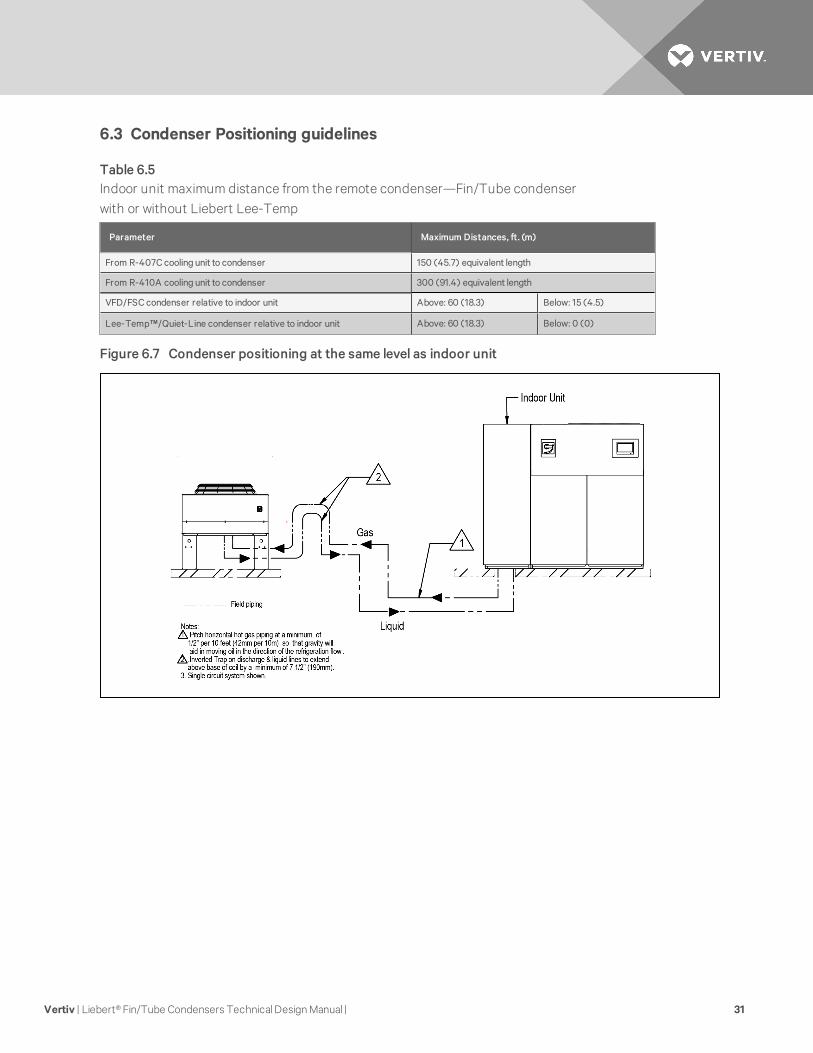
Parameter Maximum Distances, ft. (m)
From R-407C cooling unit to condenser 150 (45.7) equivalent length
From R-410A cooling unit to condenser 300 (91.4) equivalent length
VFD/FSC condenser relative to indoor unit Above: 60 (18.3) Below: 15 (4.5)
Lee-Temp™/Quiet-Line condenser relative to indoor unit Above: 60 (18.3) Below: 0 (0)
Table 6.5Indoor unit maximum distance from the remote condenser—Fin/Tube condenserwith or without Liebert Lee-Temp
Figure 6.7 Condenser positioning at the same level as indoor unit
Vertiv | Liebert® Fin/Tube Condensers TechnicalDesignManual | 31

Figure 6.8 Condenser positioning above the indoor unit
See Table 6.5 on the previous page for maximum distances between, above, and below units.
Vertiv | Liebert® Fin/Tube Condensers TechnicalDesignManual | 32

Figure 6.9 Condenser positioning below indoor unit
See Table 6.5 on page 31 for maximum distances between, above, and below units.
Vertiv | Liebert® Fin/Tube Condensers TechnicalDesignManual | 33

Figure 6.10 General arrangement—Typical Air-Cooled System Piping
Vertiv | Liebert® Fin/Tube Condensers TechnicalDesignManual | 34

7 ELECTRICAL DATAThe following tables list the electrical data for the condensers.
Vertiv | Liebert® Fin/Tube Condensers TechnicalDesignManual | 35

Vertiv | Liebert® Fin/Tube Condensers TechnicalDesignManual | 36
Mod
el#
083
,104,2
8K16
5,20
5,60K
251,
308,
90K
415
,510
616
830,1
010
#of
Fans
12
34
68
Input
Volta
ge
ph
FLA
WSA
OPD
FLA
WSA
OPD
FLA
WSA
OPD
FLA
WSA
OPD
FLA
WSA
OPD
FLA
WSA
OPD
Fan
Spe
edC
ontr
olle
d
208/
230
1
4.8
6.0
15—
——
——
——
——
——
——
——
460
2.5
3.1
15—
——
——
——
——
——
——
——
575
1.9
2.4
15—
——
——
——
——
——
——
——
208/
230
3
——
—8.
39.
515
11.8
13.0
1515
.316
.520
23.6
24.8
3030
.631
.84
0
460
——
—4
.24
.815
5.9
6.5
157.
68.
215
11.8
12.4
1515
.215
.820
575
——
—3.
33.
815
4.7
5.2
156.
16.
615
9.4
9.9
1512
.212
.715
VFD
Con
trol
led1
208/
230
33.
74
.615
7.2
8.1
1510
.711
.615
14.2
15.1
20N
/AN
/AN
/AN
/AN
/AN
/A
460
1.8
2.3
153.
54
.015
5.2
5.7
156.
97.
415
N/A
N/A
N/A
N/A
N/A
N/A
Lie
bert
Lee
-Tem
pC
ontr
olle
d/Fa
n-C
yclin
g
208/
230
3
3.5
4.4
157.
07.
915
10.5
11.4
1514
.014
.920
21.0
21.9
2528
.028
.935
460
1.7
2.1
153.
43.
815
5.1
5.5
156.
87.
215
10.2
10.6
1513
.614
.020
575
1.4
1.8
152.
83.
215
4.2
4.6
155.
66.
015
8.4
8.8
1511
.211
.615
FLA
=Fu
llL
oad
Am
ps;W
SA
=W
ire
Siz
eA
mps
;OP
D=
Max
imum
Ove
rcur
rent
Pro
tect
ion
Dev
ice
1 Whe
nL
ow-A
mbi
entV
FDH
eate
rK
itis
inst
alle
d,in
crea
seco
nden
ser
WS
Aby
1.0
Afo
r20
8 V
,1.1
Afo
r23
0 V
and
0.5
Afo
r4
60 V
.
Tab
le7.1
60Hzcond
enserd
ata

Vertiv | Liebert® Fin/Tube Condensers TechnicalDesignManual | 37
Mod
el#
063
119,1
27,1
43
214
286
409
572
#of
Fans
12
34
68
Input
Volta
ge
ph
FLA
WSA
OPD
FLA
WSA
OPD
FLA
WSA
OPD
FLA
WSA
OPD
FLA
WSA
OPD
FLA
WSA
OPD
208/
230
3
1.8
2.3
153.
64
.115
5.4
5.9
157.
27.
715
10.8
11.3
1514
.414
.920
460
0.9
1.1
151.
82.
015
2.7
2.9
153.
63.
815
5.4
5.6
157.
27.
415
575
0.7
0.9
151.
41.
615
2.1
2.3
152.
83.
015
4.2
4.4
155.
65.
815
FLA
=Fu
llL
oad
Am
ps;W
SA
=W
ire
Siz
eA
mps
;OP
D=
Max
imum
Ove
rcur
rent
Pro
tect
ion
Dev
ice
Tab
le7.2
60H
zco
nden
sere
lect
rical
data
,Lie
bert
Qui
et-L
ine™
Con
den
ser
Con
trol
Typ
e
FanSpee
d
Con
trolled
VFD
Con
trolled
Lieber
tLee
Tem
p
Con
trolled/F
an-C
yclin
g
Lieber
tQuiet
-Line
(Lieber
tLee
-Tem
p
Con
trolled/F
an-C
yclin
g)
Mod
el#
#of
Fans
Input
Volta
ge-Pha
se
Input
Volta
ge-Pha
se
Input
Volta
ge-Pha
seM
odel
#
Input
Volta
ge-Pha
se
200/2
20-1
380/4
15-3
200/2
30-3
380/4
15-3
200/2
30-3
380/4
15-3
200/2
30-3
380/4
15-3
083
,10
41
4.0
-3.
71.
83.
51.
70
631.
80
.9
165,
205
2—
3.7
7.2
3.5
7.0
3.4
119,
127,
143
3.6
1.8
251,
308
3—
5.4
10.7
5.2
10.5
5.1
214
5.4
2.7
415
,510
4—
7.1
14.2
6.9
14.0
6.8
286
7.2
3.6
616
6—
10.8
——
21.0
10.2
40
910
.85.
4
830
,10
108
—14
.2—
—28
.013
.657
214
.47.
2
Tab
le7.3
50H
zco
nden
serf
ullloa
dam
pva
lues

Rated Voltage - Single Phase 120 200/208/230
Watts/Receiver 150 300 450 150 300 450
Full Load Amps 1.4 2.8 4.2 0.7 1.4 2.1
Wire Size Amps 1.8 3.5 5.3 0.9 1.8 2.7
Maximum Overcurrent
Protection Device, Amps15 15 15 15 15 15
The Liebert Lee-Temp receiver requires a separate power feed for heaters. The condenser isnot designed to supply power to the receiver.
Table 7.4Liebert Lee-Temp™ receiver electrical data, 50Hz and 60Hz
ControlWire Run
ft (m)
Control Type
VFD & FanSpeed ControlledLiebertLee-Temp Only
Liebert Lee-TempControlled with Fan-Cycling
Number of Fans Number of Fans Number of Fans
1 2 3 4 6 8 1-4 6 & 8 2 3 4 6 8
0-25 (0-7.6)
16 16
16 16 16 16
16 16 16
16 16 16 16
26-50 (7.9-15.2) 16 16 14 16 16 16 16 16
51-75 (15.5-22.8) 16 16 14 14 16 16 16 16
76-100 (23.2-30.4) 16 16 12 12 16 16 16 16
101-125 (30.8-38.1) 16 14 10 12 16 14 16 14
126-150 (38.4-45.7) 14 14 10 10 14 14 14 14
Table based on 16AWG min. wire size, 0.4A per contactor, 1 to 1.5V maximum drop & 104°F (40°C) average ambient temperature
Table 7.5Minimum recommended control circuit wire size, AWG, 60Hz models
Vertiv | Liebert® Fin/Tube Condensers TechnicalDesignManual | 38

ControlWire Run, M (ft)
Control Type
VFD & FanSpeed ControlledLiebert Lee-TempOnly
Liebert Lee-TempControlled with Fan-Cycling
Number of Fans Number of Fans Number of Fans
1 2 3 4 6 8 1-4 6 & 8 2 3 4 6 8
0-7.6 (0-25)
1.0 1.0
1.0 1.0 1.5 1.0
1.0
1.0 1.0 1.0 1.0 1.0 1.0
7.9-15.2 (26-50) 1.0 1.0 2.5 2.5 1.0 1.0 1.0 1.0 1.0 1.0
15.5-22.8 (51-75) 1.5 1.5 4.0 4.0 1.0 1.0 1.5 1.5 1.5 1.5
23.2-30.4 (76-100) 1.5 2.5 6.0 4.0 1.0 1.0 1.5 2.5 1.5 2.5
30.8-38.1 (101-125) 2.5 2.5 6.0 6.0 1.5 1.5 2.5 2.5 2.5 2.5
38.4-45.7 (126-150) 2.5 4.0 6.0 6.0 1.5 1.5 2.5 4.0 2.5 4.0
Table based on 1.0mm2 min. wire size, 0.5A per contactor, 1 to 1.5V maximum drop & 40 °C (104 °F) average ambient temperature
Table 7.6Minimum recommended control circuit wire size, mm2, 50 Hz models
Vertiv | Liebert® Fin/Tube Condensers TechnicalDesignManual | 39

7.1 Electrical Connections
Figure 7.1 Electrical field connections for Fan-speed Control Condensers
Vertiv | Liebert® Fin/Tube Condensers TechnicalDesignManual | 40

Figure 7.2 Electrical field connections for VFD-control condensers
Vertiv | Liebert® Fin/Tube Condensers TechnicalDesignManual | 41

Figure 7.3 Electrical field connections for Liebert Lee-Temp™ and Quiet-Line control condensers
7.2 Low Voltage Control Wiring
NOTICE
Risk of control malfunction. Can cause improper unit operation. Make sure that all low voltageelectrical wiring has been performed per the schematic diagram provided and that all lowvoltage wiring connections are tight.
A control interlock between the condenser and the indoor cooling units is required. Field-supplied copperwire is required for connection between like-numbered terminals 70 & 71 on both units. Wiring must besized and selected for insulation case per NEC and other local codes. See 7 on page 35 and7 on page 35for recommended wire sizing for control wiring runs up to 150 ft (45.7 m). Contact the factory forassistance with longer wiring runs. See Figure 7.1 on page 40,Figure 7.2 on the previous page andFigure7.3 above and indoor unit manual for location of terminals on condensers and indoor units.
Vertiv | Liebert® Fin/Tube Condensers TechnicalDesignManual | 42

7.3 Low Voltage Monitoring Wiring—VFD Condensers Only
Condensers with monitoring terminals may be wired with Class 1 copper wire to the indoor cooling unit orother monitoring panel. Wiring must be sized so that the voltage drop in the circuit does not exceed 1 volt.Dry contacts close when a monitored event occurs. Consult condenser electrical schematic, supplied withthe unit, for details.
Contact closure on VFD Drive monitoring terminals indicates a healthy VFD drive. Contact open indicatesno power to condenser or a permanent VFD fault. A factory-programmed VFD must be used as thereplacement.
Contact closure on SPD monitoring terminals may indicate unit trouble ranging from electrical supplyissues to SPD replacement required. A properly trained and qualified electrician is required.
Vertiv | Liebert® Fin/Tube Condensers TechnicalDesignManual | 43

Vertiv | Liebert® Fin/Tube Condensers TechnicalDesignManual | 44
This page intentionally left blank.

APPENDICES
Appendix A: Guide Specifications for Liebert Air-cooled Condenserswith Direct-drive Propeller Fan
The following are the guide specifications for the Liebert Fin/Tube Condenser.
Vertiv | Liebert® Fin/Tube Condensers TechnicalDesignManual | 45

Vertiv | Liebert® Fin/Tube Condensers TechnicalDesignManual | 46
This page intentionally left blank.

SL-10057GS_REV2_5-16 1 Guide Specifications
Liebert® Air-Cooled Fin/Tube Condensers with Direct-drive Propeller Fan
Guide Specifications
1.0 GENERAL
1.1 Summary These specifications describe requirements for a Liebert air-cooled fin/tube condenser for a Liebert Thermal Management system. The condenser shall be designed to reject waste heat to outdoor air and to control refrigerant head pressure as outdoor ambient conditions change.
The manufacturer shall design and furnish all equipment in the quantities and configurations shown on the project drawings.
Standard 60Hz units are CSA certified to the harmonized U. S. and Canadian product safety standard CSA C22.2 No 236/UL 1995 for “Heating and Cooling Equipment” and are marked with the CSA c-us logo.
The condenser model number shall be: ____________________________
1.2 Design Requirements The condenser shall be a factory-assembled unit, complete with integral electrical panel, designed for outdoor installation. (The condenser shall be a draw-through design.)
The condenser shall have a total heat rejection capacity of _____ kW (kBtuh) rated at an outdoor ambient of _____ °F (°C) and a midpoint condensing temperature of ______ °F (°C) and a refrigerant flow to produce a subcooling of 5°F (2.8°C)
The unit is to be supplied for operation using a _____ volt_____ phase, _____Hz power supply.
1.3 Submittals Submittals shall be provided with the proposal and shall include: Dimensional, Electrical and Capacity data; Piping and Electrical Connection Drawings.
1.4 Quality Assurance The specified system shall be factory-tested before shipment. Testing shall include, but shall not be limited to: Quality Control Checks, “Hi-Pot” Test (two times rated voltage plus 1000V, per NRTL agency requirements), and Metering Calibration Tests. The system shall be designed and manufactured according to world-class quality standards. The manufacturer shall be ISO 9001 certified.

Liebert® Air-cooled Condensers
SL-10057GS_REV2 2 Guide Specifications
2.0 PRODUCT
2.1 Standard Features—All Condensers Condenser shall consist of condenser coil(s), housing, propeller fan(s) direct-driven by individual fan motor(s), electrical controls and mounting legs. The Liebert air-cooled condenser shall provide positive refrigerant head pressure control to the indoor cooling unit by adjusting heat rejection capacity. Various methods shall be available to match indoor unit type, minimum outdoor design ambient and maximum sound requirements.
2.1.1 Condenser Coil Liebert-manufactured coil shall be constructed of copper tubes in a staggered tube pattern. Tubes are expanded into continuous, corrugated aluminum fins. The fins have full-depth fin collars completely covering the copper tubes, which are connected to heavy wall Type “L” headers. Inlet coil connector tubes pass through relieved holes in the tube sheet for maximum resistance to piping strain and vibration. Coil shall be [(single circuit) (dual circuit)]. The hot-gas and liquid lines shall be spun shut and shall include a factory-installed Schrader valve. Coils shall be factory leak-tested at a minimum of 300 psig (2068kPa), dehydrated, then filled and sealed with a low pressure inert gas holding charge for shipment. Field relief of the Schrader valve shall indicate a leak-free system.
2.1.2 Housing The condenser housing shall be constructed of bright aluminum sheet and divided into individual fan sections by full-width baffles. Structural support members, including coil support frame, motor and drive support, are galvanized steel for strength and corrosion resistance. Aluminum legs shall be provided to mount unit for vertical air discharge and have rigging holes for hoisting the unit into position. An electrical panel shall be inside an integral NEMA 3R weatherproof section of the housing.
2.1.3 Propeller Fan Propeller fan shall have aluminum blades secured to corrosion protected steel hub. Fans shall be secured to the fan motor shaft by means of the keyed hub and dual setscrews. Fan diameter shall be 26" (660mm) or less. Fans shall be factory-balanced and run before shipment. Fan guards shall be heavy gauge, close-meshed steel wire with corrosion resistant polyester paint finish that shall be rated to pass a 1000-hour salt spray test.
2.1.4 Fan Motor Fan motor shall be continuous air-over design and shall be equipped with rain shield and permanently sealed bearing. Motors shall be rigidly mounted on die-formed galvanized steel supports.
2.1.5 Electrical Controls Electrical controls, overload protection devices and service connection terminals shall be provided and factory wired inside the integral electrical panel section of the housing. A locking disconnect switch shall be factory-mounted and wired to the electrical panel and controlled via an externally mounted locking door handle. An indoor unit interlock circuit shall enable condenser operation whenever indoor unit compressors are active. Only supply wiring and indoor unit interlock wiring are required at condenser installation.

Liebert® Air-cooled Condensers
SL-10057GS_REV2 3 Guide Specifications
2.2 Specific Features by Condenser Type
2.2.1 Variable Frequency Drive (VFD) Condenser (1-4 Fan) The VFD condenser shall have a variable frequency drive controlling one inverter duty, variable speed motor and On/Off fan motor(s) (for multiple fan models only) to vary the airflow across the coil. The VFD shall use one or more pressure transducers to sense refrigerant pressure to adjust fan speed to a positive head pressure control range. The inverter duty motor shall have permanently lubricated ceramic ball bearings. The Liebert variable frequency drive control system shall provide overload protection for the variable speed motor. On/Off fan motor(s) shall have individual internal overload protection and shall be controlled by ambient air thermostat(s) increasing/decreasing condenser capacity in stepped increments. Motors shall have a TEAO enclosure and a full speed of 1140RPM @ 60Hz (950RPM @ 50Hz). An internal Surge Protective Device (SPD) shall protect the VFD from power surges. Alarm contacts for the SPD and VFD shall be provided for monitoring of system components.
The VFD Control system shall provide positive startup and operation in ambient temperature as low as -[0°F (–17.8°C)] [–20°F (–28.9°C) with optional, low ambient VFD heater kit]. The air-cooled condenser shall have a ____ volt, ____ ph ____ Hz power supply.
2.2.2 Fan Speed Control (FSC) Condenser (1 Fan) The FSC condenser shall have a fan speed controller sensing refrigerant pressure and varying the speed of a FSC duty motor. Motor shall be single-phase and include built-in overload protection. Motor shall have an ODP enclosure and have a full speed of 1100RPM @ 60Hz (920RPM @ 50Hz).
The fan speed control system shall provide positive startup and operation in ambient temperature as low as -20°F (-28.9°C). The air-cooled condenser shall have a ____ volt, 1 ph, ____ Hz power supply.
2.2.3 Fan Speed Control (FSC) Condenser (2, 3 or 4 Fans) The FSC condenser shall have a fan speed controller sensing refrigerant pressure and varying the speed of an FSC duty motor. Additional fan motors shall be fixed speed, cycled On/Off by ambient air thermostats to further vary the airflow across the coil. The FSC motor shall be single-phase and include built-in overload protection. FSC motor shall have an ODP enclosure and a full speed of 1100RPM @ 60Hz (920RPM @ 50Hz). The fixed speed motors shall be three-phase and have individual internal overload protection. Fixed speed motors shall have a TEAO enclosure and a full speed of 1140RPM @ 60Hz (950RPM @ 50Hz).
The Lee-Temp control system shall provide positive startup and operation in ambient temperature as low as -20°F (-28.9°C). The air-cooled condenser shall have a ____ volt, 3 ph, ____ Hz power supply.
2.2.4 Fan Speed Control (FSC) Condenser (6 & 8 Fans) The FSC condenser shall have two fan speed controllers, each sensing the refrigerant pressure of its associated refrigerant circuit and independently varying the speed of the FSC duty motor. Additional motors shall be fixed speed, cycled On/Off by ambient air thermostats to further vary the airflow across the coil. The FSC motors shall be single-phase and include built-in overload protection. FSC motors shall have an ODP enclosure and a full speed of 1100RPM @ 60Hz (920RPM @ 50Hz). The fixed speed motors shall be three-phase and have individual internal overload protection. Fixed speed motors shall have a TEAO enclosure and a full speed of 1140RPM @ 60Hz (950RPM @ 50Hz).
The fan speed control system shall provide positive startup and operation in ambient temperature as low as -20°F (-28.9°C). The air-cooled condenser shall have a ____ volt, 3 ph, ____ Hz power supply.

Liebert® Air-cooled Condensers
SL-10057GS_REV2 4 Guide Specifications
2.2.5 Liebert Lee-Temp™ Condensers (All Fan Quantities) Liebert Lee-Temp condensers shall consist of fixed speed fan motor(s), controlled by internal contactor(s). Fans shall run full speed whenever compressors are running. The fixed speed motors shall be three-phase and provide individual internal overload protection. Fixed speed motors shall have a TEAO enclosure and a full speed of 1140RPM @ 60Hz (950RPM @ 50Hz).
Each refrigerant circuit shall have an insulated, heated receiver tank with sight glasses, pressure relief valve, rotalock valve for refrigerant charge isolation and piping assembly with head pressure operated 3-way valve and check valve. Components shall be field-assembled to the condenser. The 3-way valve shall sense refrigerant head pressure and adjust the flooding charge in the condenser coil to adjust the condenser heat rejection capacity. The Liebert Lee-Temp heater shall be [(150W) (300W)], include an integral thermostat to maintain refrigerant temperature at a minimum of 85°F (29°C) and requires a separate power supply of [(208/230-1-60) (120-1-60 volt) (200/230-1-50) (110-1-50)].
This system shall allow system startup and positive head pressure control with ambient temperatures as low as -30°F (-34.4°C).
2.2.6 Liebert Quiet-Line™ Condensers (All Fan Quantities) Liebert Quiet-Line condensers shall consist of fixed speed fan motor(s), controlled by internal contactor(s). One fan per refrigerant circuit shall run at full speed with the compressor(s). Additional fan motors may be full speed or cycled based on ambient temperatures. Motors shall have a TEAO enclosure, provide individual overload protection and have a full speed of 570RPM @ 60Hz (475RPM @ 50Hz).
Each refrigerant circuit shall have an insulated, heated receiver tank with sight glasses, pressure relief valve, rotalock valve for refrigerant charge isolation and piping assembly with head pressure operated 3-way valve and check valve. Components shall be field assembled to the condenser. The 3-way valve shall sense refrigerant head pressure and adjust the flooding charge in the condenser coil to adjust the condenser heat rejection capacity. The Liebert Lee-Temp heater shall be [(150W) (300W)], include an integral thermostat to maintain refrigerant temperature at a minimum of 85°F (29°C) and requires a separate power supply of [(208/230-1-60) (120-1-60 volt) (200/230-1-50) (110-1-50)].
This system shall allow system startup and positive head pressure control with ambient temperatures as low as -30°F (-34.4°C).
3.0 EXECUTION
3.1 Installation of Air Conditioning Unit
3.1.1 General Install air conditioning unit in accordance with manufacturer’s installation instructions. Install unit plumb and level, firmly anchored in location indicated and maintain manufacturer’s recommended clearances.
3.1.2 Electrical Wiring Install and connect electrical devices furnished by manufacturer but not specified to be factory-mounted. Furnish copy of manufacturer’s electrical connection diagram submittal to electrical contractor. Install and wire per local and national codes.
3.1.3 Piping Connections Install and connect devices furnished by manufacturer but not specified to be factory-mounted. Furnish copy of manufacturer's piping connection diagram submittal to piping contractor.
Liebert® Air-cooled Condensers
SL-10057GS_REV2 5 Guide Specifications
3.1.4 Field Quality Control Start cooling units in accordance with manufacturer’s startup instructions. Test controls and demonstrate compliance with requirements. These specifications describe requirements for a computer room environmental control system. The system shall be designed to maintain temperature and humidity conditions in the rooms containing electronic equipment.
The manufacturer shall design and furnish all equipment to be fully compatible with heat dissipation requirements.

VertivCo.com | Vertiv Headquarters, 1050 Dearborn Drive, Columbus, OH, 43085, USA
© 2017VertivCo. All rights reserved. Vertiv and the Vertiv logo are trademarks or registered trademarks of VertivCo. All other names and logos referred toare trade names, trademarks or registered trademarks of their respective owners. While everyprecaution has been taken to ensure accuracyandcompleteness herein, VertivCo. assumes no responsibility, and disclaims all liability, for damages resulting from use of this information or for anyerrors oromissions. Specifications are subject to change without notice.
SL-10057_REV5_11-17/590-1695-501A