Embed Size (px)
Citation preview
AC PowerFor Business-Critical Continuity
Liebert NX™User Manual50 and 60 Hz, 30-200kVA, 400V

i
TABLE OF CONTENTS1.0 SINGLE MODULE UPS INSTALLATION . . . . . . . . . . . . . . . . . . . . . . . . . . . . . . . . . . . . . . . . .31.1 Introduction . . . . . . . . . . . . . . . . . . . . . . . . . . . . . . . . . . . . . . . . . . . . . . . . . . . . . . . . . . . . . . . . 3
1.2 Preliminary Checks . . . . . . . . . . . . . . . . . . . . . . . . . . . . . . . . . . . . . . . . . . . . . . . . . . . . . . . . . . 3
1.3 Location. . . . . . . . . . . . . . . . . . . . . . . . . . . . . . . . . . . . . . . . . . . . . . . . . . . . . . . . . . . . . . . . . . . . 41.3.1 UPS Room . . . . . . . . . . . . . . . . . . . . . . . . . . . . . . . . . . . . . . . . . . . . . . . . . . . . . . . . . . . . . . . . . . . 41.3.2 External Battery Room . . . . . . . . . . . . . . . . . . . . . . . . . . . . . . . . . . . . . . . . . . . . . . . . . . . . . . . . 41.3.3 Storage . . . . . . . . . . . . . . . . . . . . . . . . . . . . . . . . . . . . . . . . . . . . . . . . . . . . . . . . . . . . . . . . . . . . . 4
1.4 Positioning . . . . . . . . . . . . . . . . . . . . . . . . . . . . . . . . . . . . . . . . . . . . . . . . . . . . . . . . . . . . . . . . . 51.4.1 System Cabinets . . . . . . . . . . . . . . . . . . . . . . . . . . . . . . . . . . . . . . . . . . . . . . . . . . . . . . . . . . . . . . 51.4.2 30 to 40kVA UPS . . . . . . . . . . . . . . . . . . . . . . . . . . . . . . . . . . . . . . . . . . . . . . . . . . . . . . . . . . . . . 51.4.3 60-200kVA UPS . . . . . . . . . . . . . . . . . . . . . . . . . . . . . . . . . . . . . . . . . . . . . . . . . . . . . . . . . . . . . . 51.4.4 Moving the Cabinets. . . . . . . . . . . . . . . . . . . . . . . . . . . . . . . . . . . . . . . . . . . . . . . . . . . . . . . . . . . 51.4.5 Clearances. . . . . . . . . . . . . . . . . . . . . . . . . . . . . . . . . . . . . . . . . . . . . . . . . . . . . . . . . . . . . . . . . . . 61.4.6 Access . . . . . . . . . . . . . . . . . . . . . . . . . . . . . . . . . . . . . . . . . . . . . . . . . . . . . . . . . . . . . . . . . . . . . . 61.4.7 Final Positioning. . . . . . . . . . . . . . . . . . . . . . . . . . . . . . . . . . . . . . . . . . . . . . . . . . . . . . . . . . . . . . 61.4.8 Floor Anchoring . . . . . . . . . . . . . . . . . . . . . . . . . . . . . . . . . . . . . . . . . . . . . . . . . . . . . . . . . . . . . . 61.4.9 Cable Entry. . . . . . . . . . . . . . . . . . . . . . . . . . . . . . . . . . . . . . . . . . . . . . . . . . . . . . . . . . . . . . . . . . 6
1.5 External Protective Devices. . . . . . . . . . . . . . . . . . . . . . . . . . . . . . . . . . . . . . . . . . . . . . . . . . . . 61.5.1 Rectifier and Bypass Input . . . . . . . . . . . . . . . . . . . . . . . . . . . . . . . . . . . . . . . . . . . . . . . . . . . . . 71.5.2 External Battery. . . . . . . . . . . . . . . . . . . . . . . . . . . . . . . . . . . . . . . . . . . . . . . . . . . . . . . . . . . . . . 71.5.3 UPS Output . . . . . . . . . . . . . . . . . . . . . . . . . . . . . . . . . . . . . . . . . . . . . . . . . . . . . . . . . . . . . . . . . 7
1.6 Power Cables . . . . . . . . . . . . . . . . . . . . . . . . . . . . . . . . . . . . . . . . . . . . . . . . . . . . . . . . . . . . . . . 81.6.1 Cable Termination . . . . . . . . . . . . . . . . . . . . . . . . . . . . . . . . . . . . . . . . . . . . . . . . . . . . . . . . . . . . 9
1.7 Control Cables and Communication . . . . . . . . . . . . . . . . . . . . . . . . . . . . . . . . . . . . . . . . . . . . 111.7.1 Monitor Board Features . . . . . . . . . . . . . . . . . . . . . . . . . . . . . . . . . . . . . . . . . . . . . . . . . . . . . . . 11
1.8 Dry Contacts . . . . . . . . . . . . . . . . . . . . . . . . . . . . . . . . . . . . . . . . . . . . . . . . . . . . . . . . . . . . . . . 121.8.1 Input Dry Contacts. . . . . . . . . . . . . . . . . . . . . . . . . . . . . . . . . . . . . . . . . . . . . . . . . . . . . . . . . . . 121.8.2 Maintenance Bypass Cabinet Interface . . . . . . . . . . . . . . . . . . . . . . . . . . . . . . . . . . . . . . . . . . 131.8.3 External Circuit-Breaker Interface . . . . . . . . . . . . . . . . . . . . . . . . . . . . . . . . . . . . . . . . . . . . . . 131.8.4 Output Dry Contacts . . . . . . . . . . . . . . . . . . . . . . . . . . . . . . . . . . . . . . . . . . . . . . . . . . . . . . . . . 141.8.5 Emergency Power Off Input. . . . . . . . . . . . . . . . . . . . . . . . . . . . . . . . . . . . . . . . . . . . . . . . . . . . 141.8.6 External Bypass Switch Interlock . . . . . . . . . . . . . . . . . . . . . . . . . . . . . . . . . . . . . . . . . . . . . . . 16
2.0 BATTERY INSTALLATION . . . . . . . . . . . . . . . . . . . . . . . . . . . . . . . . . . . . . . . . . . . . . . . . . .172.1 Introduction . . . . . . . . . . . . . . . . . . . . . . . . . . . . . . . . . . . . . . . . . . . . . . . . . . . . . . . . . . . . . . . 17
2.2 Safety . . . . . . . . . . . . . . . . . . . . . . . . . . . . . . . . . . . . . . . . . . . . . . . . . . . . . . . . . . . . . . . . . . . . 18
2.3 Battery Cabinet . . . . . . . . . . . . . . . . . . . . . . . . . . . . . . . . . . . . . . . . . . . . . . . . . . . . . . . . . . . . 182.3.1 Introduction . . . . . . . . . . . . . . . . . . . . . . . . . . . . . . . . . . . . . . . . . . . . . . . . . . . . . . . . . . . . . . . . 182.3.2 Temperature Considerations . . . . . . . . . . . . . . . . . . . . . . . . . . . . . . . . . . . . . . . . . . . . . . . . . . . 192.3.3 Dimensions . . . . . . . . . . . . . . . . . . . . . . . . . . . . . . . . . . . . . . . . . . . . . . . . . . . . . . . . . . . . . . . . . 192.3.4 Weight . . . . . . . . . . . . . . . . . . . . . . . . . . . . . . . . . . . . . . . . . . . . . . . . . . . . . . . . . . . . . . . . . . . . 192.3.5 Circuit Breaker Features . . . . . . . . . . . . . . . . . . . . . . . . . . . . . . . . . . . . . . . . . . . . . . . . . . . . . . 192.3.6 Moving the Battery Cabinets. . . . . . . . . . . . . . . . . . . . . . . . . . . . . . . . . . . . . . . . . . . . . . . . . . . 202.3.7 Cable Entry. . . . . . . . . . . . . . . . . . . . . . . . . . . . . . . . . . . . . . . . . . . . . . . . . . . . . . . . . . . . . . . . . 202.3.8 General Arrangement Drawings . . . . . . . . . . . . . . . . . . . . . . . . . . . . . . . . . . . . . . . . . . . . . . . . 21
ii
2.4 Battery Power Cables. . . . . . . . . . . . . . . . . . . . . . . . . . . . . . . . . . . . . . . . . . . . . . . . . . . . . . . . 382.4.1 Connection Principles. . . . . . . . . . . . . . . . . . . . . . . . . . . . . . . . . . . . . . . . . . . . . . . . . . . . . . . . . 382.4.2 Fitting the Batteries. . . . . . . . . . . . . . . . . . . . . . . . . . . . . . . . . . . . . . . . . . . . . . . . . . . . . . . . . . 382.4.3 Connecting the Battery . . . . . . . . . . . . . . . . . . . . . . . . . . . . . . . . . . . . . . . . . . . . . . . . . . . . . . . 382.4.4 Battery Room Design . . . . . . . . . . . . . . . . . . . . . . . . . . . . . . . . . . . . . . . . . . . . . . . . . . . . . . . . . 38
2.5 Battery Control. . . . . . . . . . . . . . . . . . . . . . . . . . . . . . . . . . . . . . . . . . . . . . . . . . . . . . . . . . . . . 39
2.6 Battery Circuit Breaker Box . . . . . . . . . . . . . . . . . . . . . . . . . . . . . . . . . . . . . . . . . . . . . . . . . . 402.6.1 Battery Temperature Sensor—Optional . . . . . . . . . . . . . . . . . . . . . . . . . . . . . . . . . . . . . . . . . . 43
3.0 UPS MULTI-MODULE INSTALLATION . . . . . . . . . . . . . . . . . . . . . . . . . . . . . . . . . . . . . . . . .453.1 General . . . . . . . . . . . . . . . . . . . . . . . . . . . . . . . . . . . . . . . . . . . . . . . . . . . . . . . . . . . . . . . . . . . 45
3.2 Paralleled UPS Modules . . . . . . . . . . . . . . . . . . . . . . . . . . . . . . . . . . . . . . . . . . . . . . . . . . . . . 463.2.1 Cabinet Installation . . . . . . . . . . . . . . . . . . . . . . . . . . . . . . . . . . . . . . . . . . . . . . . . . . . . . . . . . . 463.2.2 External Protective Devices . . . . . . . . . . . . . . . . . . . . . . . . . . . . . . . . . . . . . . . . . . . . . . . . . . . . 473.2.3 Power Cables. . . . . . . . . . . . . . . . . . . . . . . . . . . . . . . . . . . . . . . . . . . . . . . . . . . . . . . . . . . . . . . . 473.2.4 Control Cables . . . . . . . . . . . . . . . . . . . . . . . . . . . . . . . . . . . . . . . . . . . . . . . . . . . . . . . . . . . . . . 48
3.3 Hot-Standby UPS Modules . . . . . . . . . . . . . . . . . . . . . . . . . . . . . . . . . . . . . . . . . . . . . . . . . . . 483.3.1 Cabinet Installation . . . . . . . . . . . . . . . . . . . . . . . . . . . . . . . . . . . . . . . . . . . . . . . . . . . . . . . . . . 483.3.2 External Protective Devices . . . . . . . . . . . . . . . . . . . . . . . . . . . . . . . . . . . . . . . . . . . . . . . . . . . . 483.3.3 Power Cables. . . . . . . . . . . . . . . . . . . . . . . . . . . . . . . . . . . . . . . . . . . . . . . . . . . . . . . . . . . . . . . . 49
3.4 Dual Bus System . . . . . . . . . . . . . . . . . . . . . . . . . . . . . . . . . . . . . . . . . . . . . . . . . . . . . . . . . . . 503.4.1 Cabinet Installation . . . . . . . . . . . . . . . . . . . . . . . . . . . . . . . . . . . . . . . . . . . . . . . . . . . . . . . . . . 503.4.2 External Protective Devices . . . . . . . . . . . . . . . . . . . . . . . . . . . . . . . . . . . . . . . . . . . . . . . . . . . . 503.4.3 Power Cables. . . . . . . . . . . . . . . . . . . . . . . . . . . . . . . . . . . . . . . . . . . . . . . . . . . . . . . . . . . . . . . . 503.4.4 Control Wires . . . . . . . . . . . . . . . . . . . . . . . . . . . . . . . . . . . . . . . . . . . . . . . . . . . . . . . . . . . . . . . 513.4.5 Extended Dual Bus Synchronization Option (DBS Interface Box) . . . . . . . . . . . . . . . . . . . . . 51
4.0 EXTERNAL OPTIONAL CABINETS . . . . . . . . . . . . . . . . . . . . . . . . . . . . . . . . . . . . . . . . . . . .524.1 External Maintenance Bypass Cabinets . . . . . . . . . . . . . . . . . . . . . . . . . . . . . . . . . . . . . . . . . 52
4.2 Interlock with UPS Module . . . . . . . . . . . . . . . . . . . . . . . . . . . . . . . . . . . . . . . . . . . . . . . . . . . 52
4.3 Isolation Transformer Option . . . . . . . . . . . . . . . . . . . . . . . . . . . . . . . . . . . . . . . . . . . . . . . . . 53
4.4 Top Cable Entry Option . . . . . . . . . . . . . . . . . . . . . . . . . . . . . . . . . . . . . . . . . . . . . . . . . . . . . . 54
5.0 INSTALLATION DRAWINGS. . . . . . . . . . . . . . . . . . . . . . . . . . . . . . . . . . . . . . . . . . . . . . . . .55
6.0 OPERATION . . . . . . . . . . . . . . . . . . . . . . . . . . . . . . . . . . . . . . . . . . . . . . . . . . . . . . . . . . .756.1 Introduction . . . . . . . . . . . . . . . . . . . . . . . . . . . . . . . . . . . . . . . . . . . . . . . . . . . . . . . . . . . . . . . 75
6.1.1 Split-Bypass Input . . . . . . . . . . . . . . . . . . . . . . . . . . . . . . . . . . . . . . . . . . . . . . . . . . . . . . . . . . . 766.1.2 Static Transfer Switch . . . . . . . . . . . . . . . . . . . . . . . . . . . . . . . . . . . . . . . . . . . . . . . . . . . . . . . . 766.1.3 Battery Circuit Breaker . . . . . . . . . . . . . . . . . . . . . . . . . . . . . . . . . . . . . . . . . . . . . . . . . . . . . . . 766.1.4 Battery Temperature Compensation. . . . . . . . . . . . . . . . . . . . . . . . . . . . . . . . . . . . . . . . . . . . . 766.1.5 Redundant Control Power Supply Board . . . . . . . . . . . . . . . . . . . . . . . . . . . . . . . . . . . . . . . . . 766.1.6 Socket Outlet . . . . . . . . . . . . . . . . . . . . . . . . . . . . . . . . . . . . . . . . . . . . . . . . . . . . . . . . . . . . . . . 76
6.2 Multi Module UPS—1+N . . . . . . . . . . . . . . . . . . . . . . . . . . . . . . . . . . . . . . . . . . . . . . . . . . . . . 776.2.1 Features of NX Multi-Module UPS Configurations . . . . . . . . . . . . . . . . . . . . . . . . . . . . . . . . . 776.2.2 Requirements for Paralleling of UPS Modules . . . . . . . . . . . . . . . . . . . . . . . . . . . . . . . . . . . . . 78
iii
6.3 Modes of Operation. . . . . . . . . . . . . . . . . . . . . . . . . . . . . . . . . . . . . . . . . . . . . . . . . . . . . . . . . . 786.3.1 Normal Mode . . . . . . . . . . . . . . . . . . . . . . . . . . . . . . . . . . . . . . . . . . . . . . . . . . . . . . . . . . . . . . . 786.3.2 Battery Mode (Stored Energy Mode) . . . . . . . . . . . . . . . . . . . . . . . . . . . . . . . . . . . . . . . . . . . . . 786.3.3 Auto-Restart Mode . . . . . . . . . . . . . . . . . . . . . . . . . . . . . . . . . . . . . . . . . . . . . . . . . . . . . . . . . . . 786.3.4 Bypass Mode . . . . . . . . . . . . . . . . . . . . . . . . . . . . . . . . . . . . . . . . . . . . . . . . . . . . . . . . . . . . . . . . 796.3.5 Maintenance Mode (Manual Bypass) . . . . . . . . . . . . . . . . . . . . . . . . . . . . . . . . . . . . . . . . . . . . 796.3.6 ECO Mode (Single UPS Only) . . . . . . . . . . . . . . . . . . . . . . . . . . . . . . . . . . . . . . . . . . . . . . . . . . 796.3.7 Parallel Redundancy Mode (System Expansion) . . . . . . . . . . . . . . . . . . . . . . . . . . . . . . . . . . . 796.3.8 Hot-Standby Mode . . . . . . . . . . . . . . . . . . . . . . . . . . . . . . . . . . . . . . . . . . . . . . . . . . . . . . . . . . . 796.3.9 Frequency Converter Mode . . . . . . . . . . . . . . . . . . . . . . . . . . . . . . . . . . . . . . . . . . . . . . . . . . . . 796.3.10 Source Share Mode (Co-Generation) . . . . . . . . . . . . . . . . . . . . . . . . . . . . . . . . . . . . . . . . . . . . . 79
6.4 Battery Management—Set During Commissioning. . . . . . . . . . . . . . . . . . . . . . . . . . . . . . . . 806.4.1 Normal Function. . . . . . . . . . . . . . . . . . . . . . . . . . . . . . . . . . . . . . . . . . . . . . . . . . . . . . . . . . . . . 806.4.2 Advanced Functions (Software Settings Performed by the Commissioning Engineer) . . . . . 80
6.5 Battery Protection (settings by commissioning engineer) . . . . . . . . . . . . . . . . . . . . . . . . . . . 80
7.0 OPERATING PROCEDURES . . . . . . . . . . . . . . . . . . . . . . . . . . . . . . . . . . . . . . . . . . . . . . . .817.1 Introduction . . . . . . . . . . . . . . . . . . . . . . . . . . . . . . . . . . . . . . . . . . . . . . . . . . . . . . . . . . . . . . . 81
7.2 Startup in Normal Mode . . . . . . . . . . . . . . . . . . . . . . . . . . . . . . . . . . . . . . . . . . . . . . . . . . . . . 81
7.3 Startup into ECO Mode . . . . . . . . . . . . . . . . . . . . . . . . . . . . . . . . . . . . . . . . . . . . . . . . . . . . . . 83
7.4 Battery Test Mode Procedures . . . . . . . . . . . . . . . . . . . . . . . . . . . . . . . . . . . . . . . . . . . . . . . . 837.4.1 Test Procedure . . . . . . . . . . . . . . . . . . . . . . . . . . . . . . . . . . . . . . . . . . . . . . . . . . . . . . . . . . . . . . 83
7.5 UPS Self-Test . . . . . . . . . . . . . . . . . . . . . . . . . . . . . . . . . . . . . . . . . . . . . . . . . . . . . . . . . . . . . . 847.5.1 UPS Self-Test Procedure . . . . . . . . . . . . . . . . . . . . . . . . . . . . . . . . . . . . . . . . . . . . . . . . . . . . . . 84
7.6 Maintenance Bypass Procedure and UPS Shutdown. . . . . . . . . . . . . . . . . . . . . . . . . . . . . . . 84
7.7 Isolation of One Module in a Multi-Module System. . . . . . . . . . . . . . . . . . . . . . . . . . . . . . . . 867.7.1 Multi-Module Systems With External Output CB1 . . . . . . . . . . . . . . . . . . . . . . . . . . . . . . . . . 867.7.2 Multi-Module System Without External Output Circuit Breaker 1 . . . . . . . . . . . . . . . . . . . . 87
7.8 Insertion of One Module in a Multi-Module System . . . . . . . . . . . . . . . . . . . . . . . . . . . . . . . 88
7.9 Shutdown Procedure—Complete UPS and Load Shutdown . . . . . . . . . . . . . . . . . . . . . . . . . 89
7.10 Emergency Shutdown With EPO . . . . . . . . . . . . . . . . . . . . . . . . . . . . . . . . . . . . . . . . . . . . . . 89
7.11 Reset After Shutdown for Emergency Stop (EPO Action) or Other Conditions . . . . . . . . . . 90
7.12 Auto Restart . . . . . . . . . . . . . . . . . . . . . . . . . . . . . . . . . . . . . . . . . . . . . . . . . . . . . . . . . . . . . . . 90
7.13 Language Selection . . . . . . . . . . . . . . . . . . . . . . . . . . . . . . . . . . . . . . . . . . . . . . . . . . . . . . . . . 91
7.14 Changing the Current Date and Time . . . . . . . . . . . . . . . . . . . . . . . . . . . . . . . . . . . . . . . . . . 91
7.15 Command Password . . . . . . . . . . . . . . . . . . . . . . . . . . . . . . . . . . . . . . . . . . . . . . . . . . . . . . . . . 91
8.0 OPERATOR CONTROL PANEL AND DISPLAY . . . . . . . . . . . . . . . . . . . . . . . . . . . . . . . . . . .928.1 Introduction . . . . . . . . . . . . . . . . . . . . . . . . . . . . . . . . . . . . . . . . . . . . . . . . . . . . . . . . . . . . . . . 92
8.1.1 Mimic Power Flow . . . . . . . . . . . . . . . . . . . . . . . . . . . . . . . . . . . . . . . . . . . . . . . . . . . . . . . . . . . 938.1.2 Audible Alarm (Buzzer) . . . . . . . . . . . . . . . . . . . . . . . . . . . . . . . . . . . . . . . . . . . . . . . . . . . . . . . 938.1.3 Direct Access Push Buttons (Keys) . . . . . . . . . . . . . . . . . . . . . . . . . . . . . . . . . . . . . . . . . . . . . . 948.1.4 LCD Monitor and Menu keys. . . . . . . . . . . . . . . . . . . . . . . . . . . . . . . . . . . . . . . . . . . . . . . . . . . 948.1.5 Detailed Description of Menu Items . . . . . . . . . . . . . . . . . . . . . . . . . . . . . . . . . . . . . . . . . . . . . 96
8.2 All Status and Event Messages Displayed on the UPS Front Panel. . . . . . . . . . . . . . . . . . . 98
iv
8.3 Prompt (Pop-Up) Windows. . . . . . . . . . . . . . . . . . . . . . . . . . . . . . . . . . . . . . . . . . . . . . . . . . . 103
8.4 Dynamic Energy Flow Chart and UPS Help Screen . . . . . . . . . . . . . . . . . . . . . . . . . . . . . . 104
8.5 Default Screen Saver . . . . . . . . . . . . . . . . . . . . . . . . . . . . . . . . . . . . . . . . . . . . . . . . . . . . . . . 104
9.0 OPTIONS—FOR ASSEMBLY INSIDE THE UPS CABINET . . . . . . . . . . . . . . . . . . . . . . . . . .1059.1 Protection . . . . . . . . . . . . . . . . . . . . . . . . . . . . . . . . . . . . . . . . . . . . . . . . . . . . . . . . . . . . . . . . 105
9.1.1 Redundant Back-Feed Protection . . . . . . . . . . . . . . . . . . . . . . . . . . . . . . . . . . . . . . . . . . . . . . 1059.1.2 Seismic Anchors . . . . . . . . . . . . . . . . . . . . . . . . . . . . . . . . . . . . . . . . . . . . . . . . . . . . . . . . . . . . 1059.1.3 Degree of Protection for the UPS Enclosure . . . . . . . . . . . . . . . . . . . . . . . . . . . . . . . . . . . . . . 1059.1.4 Battery Start Facility . . . . . . . . . . . . . . . . . . . . . . . . . . . . . . . . . . . . . . . . . . . . . . . . . . . . . . . . 1059.1.5 Bypass Current Sharing Inductors . . . . . . . . . . . . . . . . . . . . . . . . . . . . . . . . . . . . . . . . . . . . . 1069.1.6 Battery Ground Fault Detection . . . . . . . . . . . . . . . . . . . . . . . . . . . . . . . . . . . . . . . . . . . . . . . 1089.1.7 Replacing Dust Filters . . . . . . . . . . . . . . . . . . . . . . . . . . . . . . . . . . . . . . . . . . . . . . . . . . . . . . . 1099.1.8 Redundant Fan for Power Module. . . . . . . . . . . . . . . . . . . . . . . . . . . . . . . . . . . . . . . . . . . . . . 109
9.2 Communication and Monitoring . . . . . . . . . . . . . . . . . . . . . . . . . . . . . . . . . . . . . . . . . . . . . . 1109.2.1 OC Web Card - SNMP/HTTP Network Interface Card . . . . . . . . . . . . . . . . . . . . . . . . . . . . . 1119.2.2 Relay Card . . . . . . . . . . . . . . . . . . . . . . . . . . . . . . . . . . . . . . . . . . . . . . . . . . . . . . . . . . . . . . . . 1129.2.3 Multiport-4 Card. . . . . . . . . . . . . . . . . . . . . . . . . . . . . . . . . . . . . . . . . . . . . . . . . . . . . . . . . . . . 1139.2.4 OC485 Web Card – Modbus, Jbus, IGM Net . . . . . . . . . . . . . . . . . . . . . . . . . . . . . . . . . . . . . 1149.2.5 Remote Alarm Monitor. . . . . . . . . . . . . . . . . . . . . . . . . . . . . . . . . . . . . . . . . . . . . . . . . . . . . . . 114
10.0 TECHNICAL SPECIFICATIONS . . . . . . . . . . . . . . . . . . . . . . . . . . . . . . . . . . . . . . . . . . . . . . 11510.1 Conformity and Standards. . . . . . . . . . . . . . . . . . . . . . . . . . . . . . . . . . . . . . . . . . . . . . . . . . . 115
v
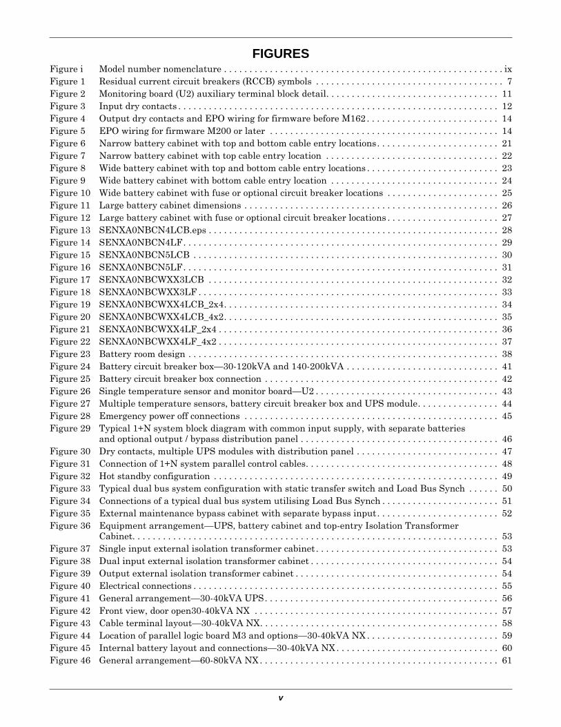
FIGURESFigure i Model number nomenclature . . . . . . . . . . . . . . . . . . . . . . . . . . . . . . . . . . . . . . . . . . . . . . . . . . . . . . . ixFigure 1 Residual current circuit breakers (RCCB) symbols . . . . . . . . . . . . . . . . . . . . . . . . . . . . . . . . . . . . . 7Figure 2 Monitoring board (U2) auxiliary terminal block detail. . . . . . . . . . . . . . . . . . . . . . . . . . . . . . . . . . 11Figure 3 Input dry contacts . . . . . . . . . . . . . . . . . . . . . . . . . . . . . . . . . . . . . . . . . . . . . . . . . . . . . . . . . . . . . . . 12Figure 4 Output dry contacts and EPO wiring for firmware before M162 . . . . . . . . . . . . . . . . . . . . . . . . . . 14Figure 5 EPO wiring for firmware M200 or later . . . . . . . . . . . . . . . . . . . . . . . . . . . . . . . . . . . . . . . . . . . . . 14Figure 6 Narrow battery cabinet with top and bottom cable entry locations. . . . . . . . . . . . . . . . . . . . . . . . 21Figure 7 Narrow battery cabinet with top cable entry location . . . . . . . . . . . . . . . . . . . . . . . . . . . . . . . . . . 22Figure 8 Wide battery cabinet with top and bottom cable entry locations . . . . . . . . . . . . . . . . . . . . . . . . . . 23Figure 9 Wide battery cabinet with bottom cable entry location . . . . . . . . . . . . . . . . . . . . . . . . . . . . . . . . . 24Figure 10 Wide battery cabinet with fuse or optional circuit breaker locations . . . . . . . . . . . . . . . . . . . . . . 25Figure 11 Large battery cabinet dimensions . . . . . . . . . . . . . . . . . . . . . . . . . . . . . . . . . . . . . . . . . . . . . . . . . . 26Figure 12 Large battery cabinet with fuse or optional circuit breaker locations . . . . . . . . . . . . . . . . . . . . . . 27Figure 13 SENXA0NBCN4LCB.eps . . . . . . . . . . . . . . . . . . . . . . . . . . . . . . . . . . . . . . . . . . . . . . . . . . . . . . . . . 28Figure 14 SENXA0NBCN4LF. . . . . . . . . . . . . . . . . . . . . . . . . . . . . . . . . . . . . . . . . . . . . . . . . . . . . . . . . . . . . . 29Figure 15 SENXA0NBCN5LCB . . . . . . . . . . . . . . . . . . . . . . . . . . . . . . . . . . . . . . . . . . . . . . . . . . . . . . . . . . . . 30Figure 16 SENXA0NBCN5LF. . . . . . . . . . . . . . . . . . . . . . . . . . . . . . . . . . . . . . . . . . . . . . . . . . . . . . . . . . . . . . 31Figure 17 SENXA0NBCWXX3LCB . . . . . . . . . . . . . . . . . . . . . . . . . . . . . . . . . . . . . . . . . . . . . . . . . . . . . . . . . 32Figure 18 SENXA0NBCWXX3LF . . . . . . . . . . . . . . . . . . . . . . . . . . . . . . . . . . . . . . . . . . . . . . . . . . . . . . . . . . . 33Figure 19 SENXA0NBCWXX4LCB_2x4. . . . . . . . . . . . . . . . . . . . . . . . . . . . . . . . . . . . . . . . . . . . . . . . . . . . . . 34Figure 20 SENXA0NBCWXX4LCB_4x2. . . . . . . . . . . . . . . . . . . . . . . . . . . . . . . . . . . . . . . . . . . . . . . . . . . . . . 35Figure 21 SENXA0NBCWXX4LF_2x4 . . . . . . . . . . . . . . . . . . . . . . . . . . . . . . . . . . . . . . . . . . . . . . . . . . . . . . . 36Figure 22 SENXA0NBCWXX4LF_4x2 . . . . . . . . . . . . . . . . . . . . . . . . . . . . . . . . . . . . . . . . . . . . . . . . . . . . . . . 37Figure 23 Battery room design . . . . . . . . . . . . . . . . . . . . . . . . . . . . . . . . . . . . . . . . . . . . . . . . . . . . . . . . . . . . . 38Figure 24 Battery circuit breaker box—30-120kVA and 140-200kVA . . . . . . . . . . . . . . . . . . . . . . . . . . . . . . 41Figure 25 Battery circuit breaker box connection . . . . . . . . . . . . . . . . . . . . . . . . . . . . . . . . . . . . . . . . . . . . . . 42Figure 26 Single temperature sensor and monitor board—U2 . . . . . . . . . . . . . . . . . . . . . . . . . . . . . . . . . . . . 43Figure 27 Multiple temperature sensors, battery circuit breaker box and UPS module. . . . . . . . . . . . . . . . 44Figure 28 Emergency power off connections . . . . . . . . . . . . . . . . . . . . . . . . . . . . . . . . . . . . . . . . . . . . . . . . . . 45Figure 29 Typical 1+N system block diagram with common input supply, with separate batteries
and optional output / bypass distribution panel . . . . . . . . . . . . . . . . . . . . . . . . . . . . . . . . . . . . . . . 46Figure 30 Dry contacts, multiple UPS modules with distribution panel . . . . . . . . . . . . . . . . . . . . . . . . . . . . 47Figure 31 Connection of 1+N system parallel control cables. . . . . . . . . . . . . . . . . . . . . . . . . . . . . . . . . . . . . . 48Figure 32 Hot standby configuration . . . . . . . . . . . . . . . . . . . . . . . . . . . . . . . . . . . . . . . . . . . . . . . . . . . . . . . . 49Figure 33 Typical dual bus system configuration with static transfer switch and Load Bus Synch . . . . . . 50Figure 34 Connections of a typical dual bus system utilising Load Bus Synch . . . . . . . . . . . . . . . . . . . . . . . 51Figure 35 External maintenance bypass cabinet with separate bypass input. . . . . . . . . . . . . . . . . . . . . . . . 52Figure 36 Equipment arrangement—UPS, battery cabinet and top-entry Isolation Transformer
Cabinet. . . . . . . . . . . . . . . . . . . . . . . . . . . . . . . . . . . . . . . . . . . . . . . . . . . . . . . . . . . . . . . . . . . . . . . . 53Figure 37 Single input external isolation transformer cabinet . . . . . . . . . . . . . . . . . . . . . . . . . . . . . . . . . . . . 53Figure 38 Dual input external isolation transformer cabinet . . . . . . . . . . . . . . . . . . . . . . . . . . . . . . . . . . . . . 54Figure 39 Output external isolation transformer cabinet . . . . . . . . . . . . . . . . . . . . . . . . . . . . . . . . . . . . . . . . 54Figure 40 Electrical connections . . . . . . . . . . . . . . . . . . . . . . . . . . . . . . . . . . . . . . . . . . . . . . . . . . . . . . . . . . . . 55Figure 41 General arrangement—30-40kVA UPS. . . . . . . . . . . . . . . . . . . . . . . . . . . . . . . . . . . . . . . . . . . . . . 56Figure 42 Front view, door open30-40kVA NX . . . . . . . . . . . . . . . . . . . . . . . . . . . . . . . . . . . . . . . . . . . . . . . . 57Figure 43 Cable terminal layout—30-40kVA NX. . . . . . . . . . . . . . . . . . . . . . . . . . . . . . . . . . . . . . . . . . . . . . . 58Figure 44 Location of parallel logic board M3 and options—30-40kVA NX . . . . . . . . . . . . . . . . . . . . . . . . . . 59Figure 45 Internal battery layout and connections—30-40kVA NX . . . . . . . . . . . . . . . . . . . . . . . . . . . . . . . . 60Figure 46 General arrangement—60-80kVA NX . . . . . . . . . . . . . . . . . . . . . . . . . . . . . . . . . . . . . . . . . . . . . . . 61
vi
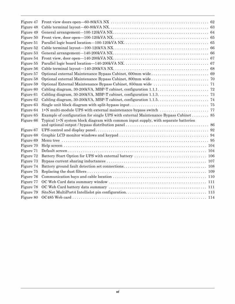
Figure 47 Front view doors open—60-80kVA NX . . . . . . . . . . . . . . . . . . . . . . . . . . . . . . . . . . . . . . . . . . . . . . 62Figure 48 Cable terminal layout—60-80kVA NX. . . . . . . . . . . . . . . . . . . . . . . . . . . . . . . . . . . . . . . . . . . . . . . 63Figure 49 General arrangement—100-120kVA NX . . . . . . . . . . . . . . . . . . . . . . . . . . . . . . . . . . . . . . . . . . . . . 64Figure 50 Front view, door open—100-120kVA NX. . . . . . . . . . . . . . . . . . . . . . . . . . . . . . . . . . . . . . . . . . . . . 65Figure 51 Parallel logic board location—100-120kVA NX. . . . . . . . . . . . . . . . . . . . . . . . . . . . . . . . . . . . . . . . 65Figure 52 Cable terminal layout—100-120kVA NX. . . . . . . . . . . . . . . . . . . . . . . . . . . . . . . . . . . . . . . . . . . . . 66Figure 53 General arrangement—140-200kVA NX . . . . . . . . . . . . . . . . . . . . . . . . . . . . . . . . . . . . . . . . . . . . . 66Figure 54 Front view, door open—140-200kVA NX. . . . . . . . . . . . . . . . . . . . . . . . . . . . . . . . . . . . . . . . . . . . . 67Figure 55 Parallel logic board location—140-200kVA NX. . . . . . . . . . . . . . . . . . . . . . . . . . . . . . . . . . . . . . . . 67Figure 56 Cable terminal layout—140-200kVA NX. . . . . . . . . . . . . . . . . . . . . . . . . . . . . . . . . . . . . . . . . . . . . 68Figure 57 Optional external Maintenance Bypass Cabinet, 600mm wide . . . . . . . . . . . . . . . . . . . . . . . . . . . 69Figure 58 Optional external Maintenance Bypass Cabinet, 800mm wide . . . . . . . . . . . . . . . . . . . . . . . . . . . 70Figure 59 Optional External Maintenance Bypass Cabinet, 850mm wide . . . . . . . . . . . . . . . . . . . . . . . . . . 71Figure 60 Cabling diagram, 30-200kVA, MBP-T cabinet, configuration 1.1.1 . . . . . . . . . . . . . . . . . . . . . . . . 72Figure 61 Cabling diagram, 30-200kVA, MBP-T cabinet, configuration 1.1.3 . . . . . . . . . . . . . . . . . . . . . . . . 73Figure 62 Cabling diagram, 30-200kVA, MBP-T cabinet, configuration 1.1.5 . . . . . . . . . . . . . . . . . . . . . . . . 74Figure 63 Single unit block diagram with split-bypass input . . . . . . . . . . . . . . . . . . . . . . . . . . . . . . . . . . . . . 75Figure 64 1+N multi-module UPS with external maintenance bypass switch . . . . . . . . . . . . . . . . . . . . . . . 77Figure 65 Example of configuration for single UPS with external Maintenance Bypass Cabinet . . . . . . . . 85Figure 66 Typical 1+N system block diagram with common input supply, with separate batteries
and optional output / bypass distribution panel . . . . . . . . . . . . . . . . . . . . . . . . . . . . . . . . . . . . . . . 86Figure 67 UPS control and display panel . . . . . . . . . . . . . . . . . . . . . . . . . . . . . . . . . . . . . . . . . . . . . . . . . . . . . 92Figure 68 Graphic LCD monitor windows and keypad . . . . . . . . . . . . . . . . . . . . . . . . . . . . . . . . . . . . . . . . . . 94Figure 69 Menu tree . . . . . . . . . . . . . . . . . . . . . . . . . . . . . . . . . . . . . . . . . . . . . . . . . . . . . . . . . . . . . . . . . . . . . 95Figure 70 Help screen . . . . . . . . . . . . . . . . . . . . . . . . . . . . . . . . . . . . . . . . . . . . . . . . . . . . . . . . . . . . . . . . . . . 104Figure 71 Default screen . . . . . . . . . . . . . . . . . . . . . . . . . . . . . . . . . . . . . . . . . . . . . . . . . . . . . . . . . . . . . . . . . 104Figure 72 Battery Start Option for UPS with external battery . . . . . . . . . . . . . . . . . . . . . . . . . . . . . . . . . . 106Figure 73 Bypass current sharing inductances . . . . . . . . . . . . . . . . . . . . . . . . . . . . . . . . . . . . . . . . . . . . . . . 107Figure 74 Battery ground fault detection set connections. . . . . . . . . . . . . . . . . . . . . . . . . . . . . . . . . . . . . . . 108Figure 75 Replacing the dust filters . . . . . . . . . . . . . . . . . . . . . . . . . . . . . . . . . . . . . . . . . . . . . . . . . . . . . . . . 109Figure 76 Communication bays and cable location . . . . . . . . . . . . . . . . . . . . . . . . . . . . . . . . . . . . . . . . . . . . 110Figure 77 OC Web Card data summary window . . . . . . . . . . . . . . . . . . . . . . . . . . . . . . . . . . . . . . . . . . . . . . 111Figure 78 OC Web Card battery data summary . . . . . . . . . . . . . . . . . . . . . . . . . . . . . . . . . . . . . . . . . . . . . . 111Figure 79 SiteNet MultiPort4 Intellislot pin configuration. . . . . . . . . . . . . . . . . . . . . . . . . . . . . . . . . . . . . . 113Figure 80 OC485 Web card . . . . . . . . . . . . . . . . . . . . . . . . . . . . . . . . . . . . . . . . . . . . . . . . . . . . . . . . . . . . . . . 114
vii
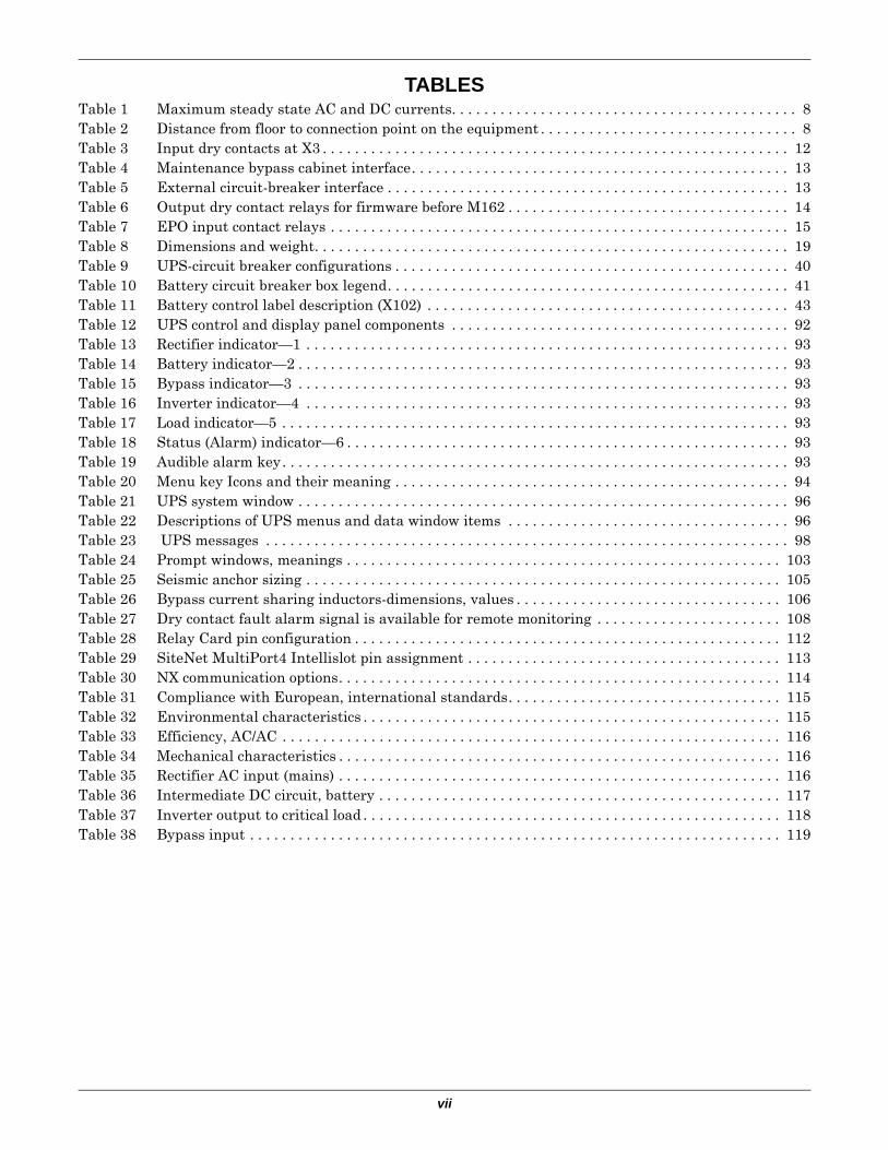
TABLESTable 1 Maximum steady state AC and DC currents. . . . . . . . . . . . . . . . . . . . . . . . . . . . . . . . . . . . . . . . . . . 8Table 2 Distance from floor to connection point on the equipment . . . . . . . . . . . . . . . . . . . . . . . . . . . . . . . . 8Table 3 Input dry contacts at X3 . . . . . . . . . . . . . . . . . . . . . . . . . . . . . . . . . . . . . . . . . . . . . . . . . . . . . . . . . . 12Table 4 Maintenance bypass cabinet interface. . . . . . . . . . . . . . . . . . . . . . . . . . . . . . . . . . . . . . . . . . . . . . . 13Table 5 External circuit-breaker interface . . . . . . . . . . . . . . . . . . . . . . . . . . . . . . . . . . . . . . . . . . . . . . . . . . 13Table 6 Output dry contact relays for firmware before M162 . . . . . . . . . . . . . . . . . . . . . . . . . . . . . . . . . . . 14Table 7 EPO input contact relays . . . . . . . . . . . . . . . . . . . . . . . . . . . . . . . . . . . . . . . . . . . . . . . . . . . . . . . . . 15Table 8 Dimensions and weight. . . . . . . . . . . . . . . . . . . . . . . . . . . . . . . . . . . . . . . . . . . . . . . . . . . . . . . . . . . 19Table 9 UPS-circuit breaker configurations . . . . . . . . . . . . . . . . . . . . . . . . . . . . . . . . . . . . . . . . . . . . . . . . . 40Table 10 Battery circuit breaker box legend. . . . . . . . . . . . . . . . . . . . . . . . . . . . . . . . . . . . . . . . . . . . . . . . . . 41Table 11 Battery control label description (X102) . . . . . . . . . . . . . . . . . . . . . . . . . . . . . . . . . . . . . . . . . . . . . 43Table 12 UPS control and display panel components . . . . . . . . . . . . . . . . . . . . . . . . . . . . . . . . . . . . . . . . . . 92Table 13 Rectifier indicator—1 . . . . . . . . . . . . . . . . . . . . . . . . . . . . . . . . . . . . . . . . . . . . . . . . . . . . . . . . . . . . 93Table 14 Battery indicator—2 . . . . . . . . . . . . . . . . . . . . . . . . . . . . . . . . . . . . . . . . . . . . . . . . . . . . . . . . . . . . . 93Table 15 Bypass indicator—3 . . . . . . . . . . . . . . . . . . . . . . . . . . . . . . . . . . . . . . . . . . . . . . . . . . . . . . . . . . . . . 93Table 16 Inverter indicator—4 . . . . . . . . . . . . . . . . . . . . . . . . . . . . . . . . . . . . . . . . . . . . . . . . . . . . . . . . . . . . 93Table 17 Load indicator—5 . . . . . . . . . . . . . . . . . . . . . . . . . . . . . . . . . . . . . . . . . . . . . . . . . . . . . . . . . . . . . . . 93Table 18 Status (Alarm) indicator—6 . . . . . . . . . . . . . . . . . . . . . . . . . . . . . . . . . . . . . . . . . . . . . . . . . . . . . . . 93Table 19 Audible alarm key. . . . . . . . . . . . . . . . . . . . . . . . . . . . . . . . . . . . . . . . . . . . . . . . . . . . . . . . . . . . . . . 93Table 20 Menu key Icons and their meaning . . . . . . . . . . . . . . . . . . . . . . . . . . . . . . . . . . . . . . . . . . . . . . . . . 94Table 21 UPS system window . . . . . . . . . . . . . . . . . . . . . . . . . . . . . . . . . . . . . . . . . . . . . . . . . . . . . . . . . . . . . 96Table 22 Descriptions of UPS menus and data window items . . . . . . . . . . . . . . . . . . . . . . . . . . . . . . . . . . . 96Table 23 UPS messages . . . . . . . . . . . . . . . . . . . . . . . . . . . . . . . . . . . . . . . . . . . . . . . . . . . . . . . . . . . . . . . . . 98Table 24 Prompt windows, meanings . . . . . . . . . . . . . . . . . . . . . . . . . . . . . . . . . . . . . . . . . . . . . . . . . . . . . . 103Table 25 Seismic anchor sizing . . . . . . . . . . . . . . . . . . . . . . . . . . . . . . . . . . . . . . . . . . . . . . . . . . . . . . . . . . . 105Table 26 Bypass current sharing inductors-dimensions, values . . . . . . . . . . . . . . . . . . . . . . . . . . . . . . . . . 106Table 27 Dry contact fault alarm signal is available for remote monitoring . . . . . . . . . . . . . . . . . . . . . . . 108Table 28 Relay Card pin configuration . . . . . . . . . . . . . . . . . . . . . . . . . . . . . . . . . . . . . . . . . . . . . . . . . . . . . 112Table 29 SiteNet MultiPort4 Intellislot pin assignment . . . . . . . . . . . . . . . . . . . . . . . . . . . . . . . . . . . . . . . 113Table 30 NX communication options. . . . . . . . . . . . . . . . . . . . . . . . . . . . . . . . . . . . . . . . . . . . . . . . . . . . . . . 114Table 31 Compliance with European, international standards. . . . . . . . . . . . . . . . . . . . . . . . . . . . . . . . . . 115Table 32 Environmental characteristics . . . . . . . . . . . . . . . . . . . . . . . . . . . . . . . . . . . . . . . . . . . . . . . . . . . . 115Table 33 Efficiency, AC/AC . . . . . . . . . . . . . . . . . . . . . . . . . . . . . . . . . . . . . . . . . . . . . . . . . . . . . . . . . . . . . . 116Table 34 Mechanical characteristics . . . . . . . . . . . . . . . . . . . . . . . . . . . . . . . . . . . . . . . . . . . . . . . . . . . . . . . 116Table 35 Rectifier AC input (mains) . . . . . . . . . . . . . . . . . . . . . . . . . . . . . . . . . . . . . . . . . . . . . . . . . . . . . . . 116Table 36 Intermediate DC circuit, battery . . . . . . . . . . . . . . . . . . . . . . . . . . . . . . . . . . . . . . . . . . . . . . . . . . 117Table 37 Inverter output to critical load . . . . . . . . . . . . . . . . . . . . . . . . . . . . . . . . . . . . . . . . . . . . . . . . . . . . 118Table 38 Bypass input . . . . . . . . . . . . . . . . . . . . . . . . . . . . . . . . . . . . . . . . . . . . . . . . . . . . . . . . . . . . . . . . . . 119

viii
Dear Customer:
Please allow us to congratulate you on choosing a Liebert manufactured Uninterruptible Power System.
If this is your first Liebert UPS, we cordially welcome you to a lifetime relationship of after-sales support designed to keep your Liebert UPS and your systems permanently at their peak performance.
If you already own and use a Liebert UPS, then we are doubly honoured by your decision to continue this valued relationship.
Our philosophy is reflected in our mission statement “Keeping Business in Business,” and with this we strive to contribute to the growth & success of your business.
Please give us your valued feedback to help us realise our mission.
EMERSON NETWORK POWER
ix
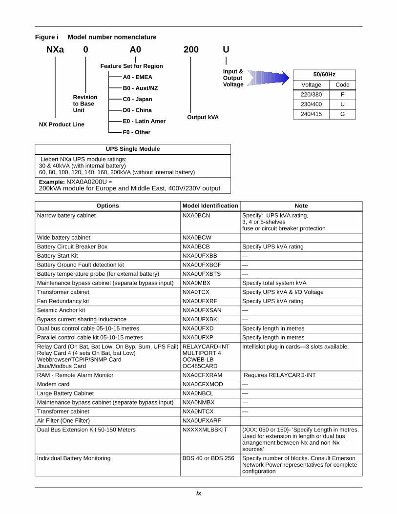
Figure i Model number nomenclature
UPS Single Module
Liebert NXa UPS module ratings:30 & 40kVA (with internal battery)60, 80, 100, 120, 140, 160, 200kVA (without internal battery)
Example: NXA0A0200U =200kVA module for Europe and Middle East, 400V/230V output
Options Model Identification NoteNarrow battery cabinet NXA0BCN Specify: UPS kVA rating,
3, 4 or 5-shelvesfuse or circuit breaker protection
Wide battery cabinet NXA0BCWBattery Circuit Breaker Box NXA0BCB Specify UPS kVA ratingBattery Start Kit NXA0UFXBB —Battery Ground Fault detection kit NXA0UFXBGF —Battery temperature probe (for external battery) NXA0UFXBTS —Maintenance bypass cabinet (separate bypass input) NXA0MBX Specify total system kVATransformer cabinet NXA0TCX Specify UPS kVA & I/O VoltageFan Redundancy kit NXA0UFXRF Specify UPS kVA ratingSeismic Anchor kit NXA0UFXSAN —Bypass current sharing inductance NXA0UFXBK —Dual bus control cable 05-10-15 metres NXA0UFXD Specify length in metresParallel control cable kit 05-10-15 metres NXA0UFXP Specify length in metresRelay Card (On Bat, Bat Low, On Byp, Sum, UPS Fail)Relay Card 4 (4 sets On Bat, bat Low)Webbrowser/TCPIP/SNMP CardJbus/Modbus Card
RELAYCARD-INTMULTIPORT 4OCWEB-LBOC485CARD
Intellislot plug-in cards—3 slots available.
RAM - Remote Alarm Monitor NXA0CFXRAM Requires RELAYCARD-INTModem card NXA0CFXMOD —Large Battery Cabinet NXA0NBCL —Maintenance bypass cabinet (separate bypass input) NXA0NMBX —Transformer cabinet NXA0NTCX —Air Filter (One Filter) NXA0UFXARF —Dual Bus Extension Kit 50-150 Meters NXXXXMLBSKIT (XXX: 050 or 150)- 'Specify Length in metres.
Used for extension in length or dual bus arrangement between Nx and non-Nx sources'
Individual Battery Monitoring BDS 40 or BDS 256 Specify number of blocks. Consult Emerson Network Power representatives for complete configuration
NXa U
NX Product Line
Revision to Base Unit
Feature Set for Region
A0 - EMEA
B0 - Aust/NZ
C0 - Japan
D0 - China
E0 - Latin Amer
F0 - Other
Input & Output Voltage
50/60Hz
Voltage Code
220/380 F
230/400 U
240/415 G
0 A0 200
Output kVA

x
1
SAFETY PRECAUTIONSThis manual contains information concerning the installation and operation of this Emerson Network Power Liebert NX Uninterruptible Power System (UPS).
This manual should be read before commencing installation.
The UPS must be commissioned and serviced by an engineer approved by the manufacturer (or agent).
Failure to do so could result in personnel safety risk, equipment malfunction and invalidation of war-ranty.
The Liebert NX has been designed for Commercial/Industrial use only, and is not recommended for use in life support applications.
This is a low emission CLASS A Uninterruptible Power System (UPS) product. In a residential envi-ronment, this product may nevertheless cause radio interference, in which case, the user may be required to take additional measures.
Conformity and StandardsThis equipment complies with CE directives 73/23 & 93/68 (LV Safety) and 89/336 (EMC), with Aus-tralia and New Zealand EMC Framework (C-Tick) and with the following product standards for Unin-terruptible Power System (UPS).
• EN / IEC / AS 62040-1-1—General and safety requirements for use in operator access area• EN / IEC / AS 62040-2—EMC requirements; Class A compliant• EN / IEC / AS 62040-3—Performance requirements and test methods
For more details, see 10.0 - Technical Specifications
Continued compliance requires installation in accordance with these instructions and the use of man-ufacturer approved accessories only.
! WARNINGHigh Leakage Current
EARTH CONNECTION IS ESSENTIAL BEFORE CONNECTING THE INPUT SUPPLY.
Earth leakage current exceeds 3.5 mA and is less than 1000 mA for 30-80kVA, less than 2000mA for 100-120kVA. models and less than 2500mA for 140-200kVA models.
Transient and steady-state earth leakage currents, which may occur when starting the equipment, should be taken into account when selecting instantaneous RCCB or RCD devices.
Residual Current Circuit Breakers (RCCBs) must be selected sensitive to DC unidirectional pulses (class A) and insensitive to transient current pulses.
Note also that the earth leakage currents of the load will be carried by this RCCB or RCD.
This equipment must be earthed in accordance with the local electrical code of practice.
! WARNINGBack-Feed Protection Notice
This UPS is fitted with a voltage-free contact closure signal for use with an external automatic disconnect device (supplied by others) to protect against back-feeding voltage into the bypass input. If this signal is not used by the installer, a label must be added at the external bypass input disconnect device to warn service personnel that the circuit is connected to a UPS.
The text to use is the following or equivalent:
ISOLATE THE UNINTERRUPTIBLE POWER SYSTEM BEFORE WORKING ON THIS CIRCUIT.
2
User-Serviceable PartsAll equipment maintenance and servicing procedures involving internal access requires the use of a tool and should be carried out only by trained personnel. There are no user-serviceable parts behind covers requiring a tool for removal.
This UPS is fully compliant with safety regulations for equipment located in an operator accessible area. Hazardous voltage is present within the UPS and battery enclosure but out of reach of non-ser-vice personnel. Contact with hazardous voltage is minimized by housing live parts behind safety pan-els that require a tool for their removal. No risk exists to any personnel when operating the equipment in the normal manner, following the recommended operating procedures.
Battery Voltage Exceeds 400VDC All physical battery maintenance and servicing requires the use of a tool or a key and should be car-ried out only by trained personnel.
Battery manufacturers supply details of the necessary precautions to be observed when working on, or in the vicinity of, a large bank of battery cells. These precautions should be followed implicitly at all times.
Attention should be paid to the recommendations concerning local environmental conditions and the provision of protective clothing, first aid and fire-fighting facilities.
! WARNINGSpecial care should be taken when working with the batteries associated with this equipment.
When connected together, the battery terminal voltage will exceed 400VDC and is potentially lethal.
Single Module UPS Installation
3
1.0 SINGLE MODULE UPS INSTALLATION
1.1 IntroductionThis following section describes the requirements that must be taken into account when planning the positioning and cabling of the Liebert NX uninterruptible power supply and related equipment.
This chapter is a guide to general procedures and practices that should be observed by the installing engineer. The particular conditions of each site will determine the applicability of such procedures.
1.2 Preliminary ChecksBefore installing the UPS, please carry out the following preliminary checks:
1. Visually examine the UPS and battery equipment for transit damage, both internally and externally. Report any damage to the shipper immediately.
2. Verify that the correct equipment is being installed. The equipment supplied has an identification tag on the back of the main door reporting: the type, size and main calibration parameters of the UPS.
! WARNINGProfessional Installation Required
Do not apply electrical power to the UPS equipment before being authorised to do so by the commissioning engineer.
The UPS equipment shall be installed by a qualified electrical tradesperson in accordance with the information contained in this manual. All equipment not referred to this manual is shipped with details of its own mechanical and electrical installation.
NOTEThree-phase, 4-wire input supply required.
The standard Liebert NX UPS is suitable for connection to 3-phase, 4-wire (+ Earth) TN, TT and IT AC power distribution systems (IEC60364-3). Optional 3-wire to 4-wire conversion transformers are available. If it is used in IT AC power distribution systems, a 4-pole circuit breaker must be used on the input and refer to the relative IT Systems’ standard
! WARNINGBattery Hazards
Special care should be taken when working with the batteries associated with this equipment. When connected together, the battery terminal voltage will exceed 400VDC and is hazardous.
Eye protection should be worn to prevent injury from accidental electrical arcs.
Remove rings, watches and all other metal objects.
Use only tools with insulated handles.
Wear rubber gloves.
If a battery leaks electrolyte or is otherwise physically damaged, it must be replaced, stored in a container resistant to sulfuric acid and disposed of in accordance with local regulations.
If electrolyte comes into contact with the skin, the affected area should be washed immediately with water.
Single Module UPS Installation
4
1.3 Location
1.3.1 UPS RoomThe UPS and its internal battery is intended for indoor installation and should be located in an envi-ronment with clean air and with adequate ventilation to keep the ambient temperature within the specified operating range (see Table 33).
All models in the Liebert NX UPS range are air-cooled with the aid of internal fans. Cold air enters through ventilation grilles at the front of the cabinet for NXa 30-120kVA and through ventilation grilles located at the front and bottom of the cabinet for NXa 140-200kVA. Hot air is released through grilles at the top. Do not cover the ventilation openings.
If necessary to avoid room temperature build-up, install a system of room extractor fans. Optional air filters are available if the UPS is to operate in a dusty environment.
The UPS heat dissipation detailed in Table 34 can be used as a guide for air conditioning sizing, depending on the selected mode of operation:
• Normal Mode (VFI SS 111 Double Conversion UPS)• ECO Mode (VFD SS 311 Stand By UPS)
If in doubt use Normal Mode figures.
1.3.2 External Battery RoomBatteries should be mounted in an environment where the temperature is consistent and even over the whole battery. Temperature is a major factor in determining the battery life and capacity. Typical battery manufacturer performance data are quoted for an operating temperature between 20 and 25°C (68 and 77°F). Operating above this range will reduce the battery life while operation below this range will reduce the battery capacity. In a normal installation the battery temperature is main-tained between 15°C and 25°C (59 and 77°F). Keep batteries away from main heat sources or main air inlets etc.
Where the batteries are located externally to the main UPS cabinet, a battery protection device (e.g., fuses or circuit breakers) must be mounted as close as possible to the batteries themselves, and connected using the most direct route possible.
1.3.3 StorageShould the equipment not be installed immediately, it must be stored in a room for protection against excessive humidity and or heat sources (see Table 33).
NOTEThe UPS is suitable for mounting on concrete or other non-combustible surface only.
! CAUTIONAn unused battery must be recharged periodically per battery manufacturer recommendation. Temporarily connecting the UPS to a suitable AC supply mains and activating it for the time required for recharging the batteries can achieve this.
Single Module UPS Installation
5
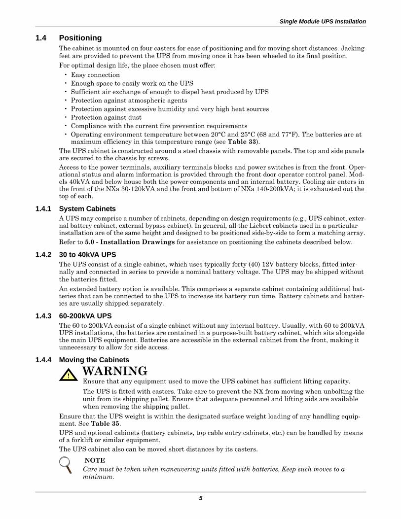
1.4 PositioningThe cabinet is mounted on four casters for ease of positioning and for moving short distances. Jacking feet are provided to prevent the UPS from moving once it has been wheeled to its final position.For optimal design life, the place chosen must offer:
• Easy connection• Enough space to easily work on the UPS• Sufficient air exchange of enough to dispel heat produced by UPS• Protection against atmospheric agents• Protection against excessive humidity and very high heat sources• Protection against dust• Compliance with the current fire prevention requirements• Operating environment temperature between 20°C and 25°C (68 and 77°F). The batteries are at
maximum efficiency in this temperature range (see Table 33).The UPS cabinet is constructed around a steel chassis with removable panels. The top and side panels are secured to the chassis by screws. Access to the power terminals, auxiliary terminals blocks and power switches is from the front. Oper-ational status and alarm information is provided through the front door operator control panel. Mod-els 40kVA and below house both the power components and an internal battery. Cooling air enters in the front of the NXa 30-120kVA and the front and bottom of NXa 140-200kVA; it is exhausted out the top of each.
1.4.1 System CabinetsA UPS may comprise a number of cabinets, depending on design requirements (e.g., UPS cabinet, exter-nal battery cabinet, external bypass cabinet). In general, all the Liebert cabinets used in a particular installation are of the same height and designed to be positioned side-by-side to form a matching array.Refer to 5.0 - Installation Drawings for assistance on positioning the cabinets described below.
1.4.2 30 to 40kVA UPSThe UPS consist of a single cabinet, which uses typically forty (40) 12V battery blocks, fitted inter-nally and connected in series to provide a nominal battery voltage. The UPS may be shipped without the batteries fitted.An extended battery option is available. This comprises a separate cabinet containing additional bat-teries that can be connected to the UPS to increase its battery run time. Battery cabinets and batter-ies are usually shipped separately.
1.4.3 60-200kVA UPSThe 60 to 200kVA consist of a single cabinet without any internal battery. Usually, with 60 to 200kVA UPS installations, the batteries are contained in a purpose-built battery cabinet, which sits alongside the main UPS equipment. Batteries are accessible in the external cabinet from the front, making it unnecessary to allow for side access.
1.4.4 Moving the Cabinets
Ensure that the UPS weight is within the designated surface weight loading of any handling equip-ment. See Table 35.UPS and optional cabinets (battery cabinets, top cable entry cabinets, etc.) can be handled by means of a forklift or similar equipment. The UPS cabinet also can be moved short distances by its casters.
!
WARNINGEnsure that any equipment used to move the UPS cabinet has sufficient lifting capacity.
The UPS is fitted with casters. Take care to prevent the NX from moving when unbolting the unit from its shipping pallet. Ensure that adequate personnel and lifting aids are available when removing the shipping pallet.
NOTECare must be taken when maneuvering units fitted with batteries. Keep such moves to a minimum.
Single Module UPS Installation
6
1.4.5 ClearancesThe Liebert NX has no ventilation grilles at either side of the UPS. To enable routine tightening of power terminations within the UPS, in addition to meeting any local regulations, Liebert recom-mends providing adequate clearance in the front of the equipment for unimpeded passage of person-nel with the doors fully opened. It is important to leave 800mm (31.5") clearance above the UPS to permit adequate circulation of air coming out of the unit.
1.4.6 AccessThe component layout of the UPS supports front and top access while servicing, diagnosing and repairing the UPS, thus reducing the space requirement for side and rear access.
1.4.7 Final PositioningThe UPS cabinets are fitted with casters on the base to allow ease of movement and positioning.
When the equipment has been finally positioned, ensure the adjustable feet are set so that the UPS will remain stationary and stable.
1.4.8 Floor AnchoringDiagrams in 5.0 - Installation Drawings show the location of the holes in the base plate through which the equipment may be bolted to the floor. If the equipment is to be installed on a raised floor it should be mounted on a pedestal suitably designed to accept the equipment point loading.
1.4.9 Cable EntryCables can enter the Liebert NX UPS and battery cabinet from below. Cable entry is made possible by removing a blanking piece fitted at the bottom of equipment to reveal the cable entry hole.
Top Cable Entry—OptionalOptionally a top cable entry extension may be used. The cabinet extends the overall width of the UPS and permits connection of all incoming AC/DC power cables from above.
The top cable entry option is fitted on the side of the UPS cabinet and is supplied without side panels; the side cover from the UPS being used.
The cabinet with cables coming in from the top for the 30-40 kVA UPS must be positioned on the left side; the cabinet for the 60 to 200 kVA UPS can be positioned on either side.
This facilitates cable entry through the top metal panel after the appropriate cable entry holes have been cut.
1.5 External Protective DevicesCircuit breakers or other protective devices must be installed in the AC supply, external to the UPS. This chapter provides guidelines for qualified installers who must have knowledge of local wiring practices pertaining to the equipment to be installed.
! WARNING Casters are strong enough for movement across even surfaces only. Caster failure could occur if they are subjected to shock loading.
NOTEThe top cable entry also includes the power connection cables between the cabinet and the UPS.
Single Module UPS Installation
7
1.5.1 Rectifier and Bypass InputOvercurrent protection must be installed at the distribution panel of the incoming main supply. The protection must discriminate with the power cables current capacity and with the overload capacity of the system (see Table 38). As a guideline, a thermomagnetic circuit breaker, with an IEC 60947-2 trip curve C (normal) for 125% of the current listed in Table 1 is suitable.
Split-Bypass—If a split-bypass is used, install separate protective devices for the rectifier and for the bypass in the incoming mains distribution panel.
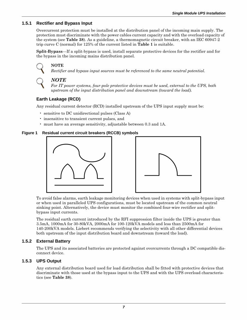
Earth Leakage (RCD)Any residual current detector (RCD) installed upstream of the UPS input supply must be:
• sensitive to DC unidirectional pulses (Class A)• insensitive to transient current pulses, and• must have an average sensitivity, adjustable between 0.3 and 1A.
Figure 1 Residual current circuit breakers (RCCB) symbols
To avoid false alarms, earth leakage monitoring devices when used in systems with split-bypass input or when used in paralleled UPS configurations, must be located upstream of the common neutral sinking point. Alternatively, the device must monitor the combined four-wire rectifier and split-bypass input currents.
The residual earth current introduced by the RFI suppression filter inside the UPS is greater than 3.5mA, 1000mA for 30-80kVA, 2000mA for 100-120kVA models and less than 2500mA for 140-200kVA models. Liebert recommends verifying the selectivity with all other differential devices both upstream of the input distribution board and downstream (toward the load).
1.5.2 External BatteryThe UPS and its associated batteries are protected against overcurrents through a DC compatible dis-connect device.
1.5.3 UPS OutputAny external distribution board used for load distribution shall be fitted with protective devices that discriminate with those used at the bypass input to the UPS and with the UPS overload characteris-tics (see Table 38).
NOTERectifier and bypass input sources must be referenced to the same neutral potential.
NOTEFor IT power systems, four-pole protective devices must be used, external to the UPS, both upstream of the input distribution panel and downstream (toward the load).
Single Module UPS Installation
8
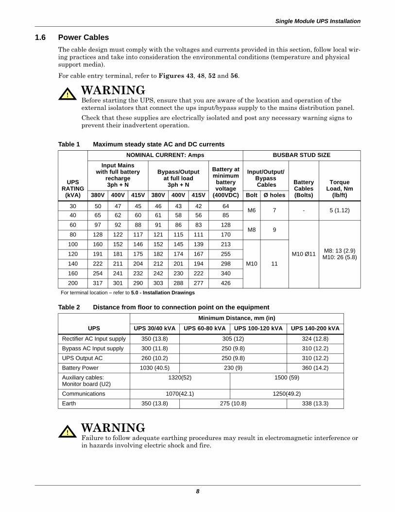
1.6 Power CablesThe cable design must comply with the voltages and currents provided in this section, follow local wir-ing practices and take into consideration the environmental conditions (temperature and physical support media).
For cable entry terminal, refer to Figures 43, 48, 52 and 56.
!
WARNINGBefore starting the UPS, ensure that you are aware of the location and operation of the external isolators that connect the ups input/bypass supply to the mains distribution panel.
Check that these supplies are electrically isolated and post any necessary warning signs to prevent their inadvertent operation.
Table 1 Maximum steady state AC and DC currents
UPSRATING
(kVA)
NOMINAL CURRENT: Amps BUSBAR STUD SIZE
Input Mainswith full battery
recharge3ph + N
Bypass/Outputat full load
3ph + N
Battery atminimumbatteryvoltage
(400VDC)
Input/Output/Bypass Cables Battery
Cables(Bolts)
TorqueLoad, Nm
(lb/ft)380V 400V 415V 380V 400V 415V Bolt Ø holes
30 50 47 45 46 43 42 64M6 7 - 5 (1.12)
40 65 62 60 61 58 56 85
60 97 92 88 91 86 83 128M8 9
M10 Ø11 M8: 13 (2.9)M10: 26 (5.8)
80 128 122 117 121 115 111 170
100 160 152 146 152 145 139 213
M10 11
120 191 181 175 182 174 167 255
140 222 211 204 212 201 194 298
160 254 241 232 242 230 222 340
200 317 301 290 303 288 277 426For terminal location – refer to 5.0 - Installation Drawings
Table 2 Distance from floor to connection point on the equipment
UPS
Minimum Distance, mm (in)
UPS 30/40 kVA UPS 60-80 kVA UPS 100-120 kVA UPS 140-200 kVA
Rectifier AC Input supply 350 (13.8) 305 (12) 324 (12.8)
Bypass AC Input supply 300 (11.8) 250 (9.8) 310 (12.2)
UPS Output AC 260 (10.2) 250 (9.8) 310 (12.2)
Battery Power 1030 (40.5) 230 (9) 360 (14.2)
Auxiliary cables:Monitor board (U2)
1320(52) 1500 (59)
Communications 1070(42.1) 1250(49.2)
Earth 350 (13.8) 275 (10.8) 338 (13.3)
! WARNINGFailure to follow adequate earthing procedures may result in electromagnetic interference or in hazards involving electric shock and fire.
Single Module UPS Installation
9
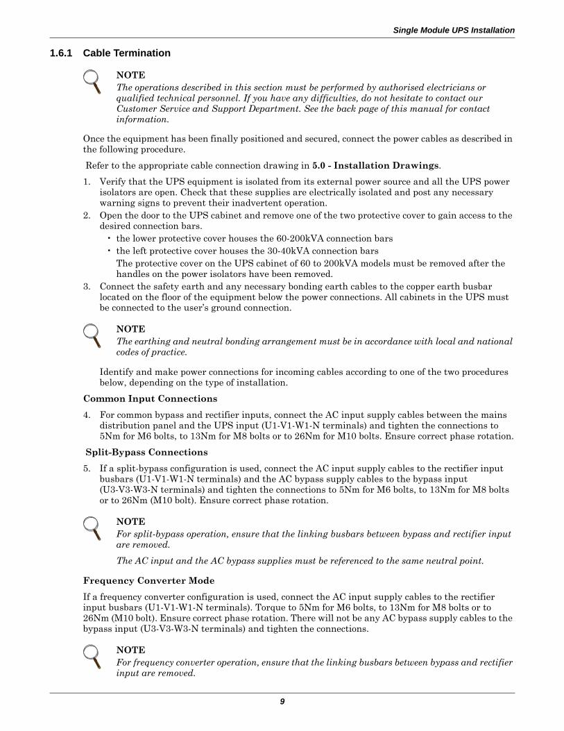
1.6.1 Cable Termination
Once the equipment has been finally positioned and secured, connect the power cables as described in the following procedure.
Refer to the appropriate cable connection drawing in 5.0 - Installation Drawings.
1. Verify that the UPS equipment is isolated from its external power source and all the UPS power isolators are open. Check that these supplies are electrically isolated and post any necessary warning signs to prevent their inadvertent operation.
2. Open the door to the UPS cabinet and remove one of the two protective cover to gain access to the desired connection bars.
• the lower protective cover houses the 60-200kVA connection bars• the left protective cover houses the 30-40kVA connection bars
The protective cover on the UPS cabinet of 60 to 200kVA models must be removed after the handles on the power isolators have been removed.
3. Connect the safety earth and any necessary bonding earth cables to the copper earth busbar located on the floor of the equipment below the power connections. All cabinets in the UPS must be connected to the user’s ground connection.
Identify and make power connections for incoming cables according to one of the two procedures below, depending on the type of installation.
Common Input Connections
4. For common bypass and rectifier inputs, connect the AC input supply cables between the mains distribution panel and the UPS input (U1-V1-W1-N terminals) and tighten the connections to 5Nm for M6 bolts, to 13Nm for M8 bolts or to 26Nm for M10 bolts. Ensure correct phase rotation.
Split-Bypass Connections
5. If a split-bypass configuration is used, connect the AC input supply cables to the rectifier input busbars (U1-V1-W1-N terminals) and the AC bypass supply cables to the bypass input (U3-V3-W3-N terminals) and tighten the connections to 5Nm for M6 bolts, to 13Nm for M8 bolts or to 26Nm (M10 bolt). Ensure correct phase rotation.
Frequency Converter Mode
If a frequency converter configuration is used, connect the AC input supply cables to the rectifier input busbars (U1-V1-W1-N terminals). Torque to 5Nm for M6 bolts, to 13Nm for M8 bolts or to 26Nm (M10 bolt). Ensure correct phase rotation. There will not be any AC bypass supply cables to the bypass input (U3-V3-W3-N terminals) and tighten the connections.
NOTEThe operations described in this section must be performed by authorised electricians or qualified technical personnel. If you have any difficulties, do not hesitate to contact our Customer Service and Support Department. See the back page of this manual for contact information.
NOTEThe earthing and neutral bonding arrangement must be in accordance with local and national codes of practice.
NOTEFor split-bypass operation, ensure that the linking busbars between bypass and rectifier input are removed.
The AC input and the AC bypass supplies must be referenced to the same neutral point.
NOTEFor frequency converter operation, ensure that the linking busbars between bypass and rectifier input are removed.
Single Module UPS Installation
10
Output System Connections
6. Connect the system output cables between the UPS output (U2-V2-W2-N terminals) and the critical load and tighten the connections to 5Nm for M6 bolts, to 13Nm for M8 bolts or to 26Nm for M10 bolts. Ensure correct phase rotation.
External UPS Battery Connection (60kVA Models and Above, Option for 30-40kVA Models)
Connect the battery cables between the UPS terminals (+\-) and its associated battery circuit breaker. Observe the battery cable polarity.
Internal UPS Battery Connection (30/40kVA only)
7. The battery consists of a series string connection of 5 x 8 (or 10) x 12V 6-cell battery blocks.a. Ensure that the eight (or 10) battery blocks in each tier (tray) are interconnected.b. Connect the positive and negative cables to the UPS terminals.c. Plug in the cables between the tiers.d. Ensure correct polarity battery string series connections (i.e., intertier and
interblock connections are from positive to negative terminals.
8. Refit all protective covers removed for cable installation.
NOTEWhen connecting the cables between the battery extremities to the circuit breaker always connect the circuit breaker end of the cable first.
! WARNINGIf the load equipment will not be ready to accept power on the arrival of the commissioning engineer, ensure that the system output cables are safely isolated at their ends.
! WARNINGHazardous Battery Terminal Voltage 480VDC
Ensure correct polarity of string end connections to the UPS terminals, i.e., positive to positive and negative to negative, but leave these UPS terminal cables disconnected until connection is authorised by the commissioning engineer.
Ensure correct polarity of string end connections to the battery circuit breaker and from the battery circuit breaker to the UPS terminals, i.e., positive to positive and negative to negative, but disconnect one or more battery cell links in each tier.
Do not reconnect these links and do not close the battery circuit breaker before authorised by the commissioning engineer.
Single Module UPS Installation
11
1.7 Control Cables and Communication
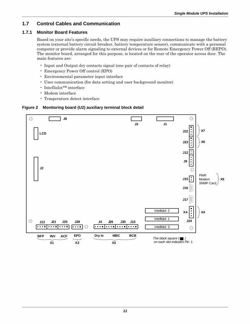
1.7.1 Monitor Board FeaturesBased on your site’s specific needs, the UPS may require auxiliary connections to manage the battery system (external battery circuit breaker, battery temperature sensor), communicate with a personal computer or provide alarm signaling to external devices or for Remote Emergency Power Off (REPO). The monitor board, arranged for this purpose, is located on the rear of the operator access door. The main features are:
• Input and Output dry contacts signal (one pair of contacts of relay)• Emergency Power Off control (EPO)• Environmental parameter input interface• User communication (for data setting and user background monitor)• Intellislot™ interface• Modem interface• Temperature detect interface
Figure 2 Monitoring board (U2) auxiliary terminal block detail
Intellislot 2
Intellislot 1
Intellislot 3
J1J3
J22
J23
J12
J9
X4
J15
J16
J17
J24J10J30J26J4J28J25J21J13
Dry In MBC BCBBFP INV ACF EPO
X1 X2 X3
J2
LCD
J8
X7
X6
X5
X4
PWRModemSNMP Card
The black square ( ) on each slot indicates Pin 1.
Single Module UPS Installation
12
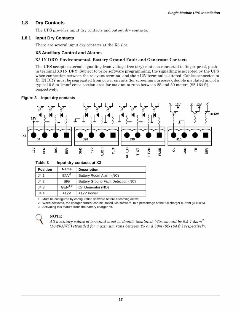
1.8 Dry ContactsThe UPS provides input dry contacts and output dry contacts.
1.8.1 Input Dry ContactsThere are several input dry contacts at the X3 slot.
X3 Ancillary Control and AlarmsX3 IN DRY: Environmental, Battery Ground Fault and Generator Contacts
The UPS accepts external signalling from voltage-free (dry) contacts connected to finger-proof, push-in terminal X3 IN DRY. Subject to prior software programming, the signalling is accepted by the UPS when connection between the relevant terminal and the +12V terminal is altered. Cables connected to X3 IN DRY must be segregated from power circuits (for screening purposes), double insulated and of a typical 0.5 to 1mm2 cross-section area for maximum runs between 25 and 50 meters (82-164 ft), respectively.
Figure 3 Input dry contacts
Table 3 Input dry contacts at X3
Position Name Description J4.1 ENV3 Battery Room Alarm (NC)
J4.2 BtG Battery Ground Fault Detection (NC)
J4.3 GEN1,2 On Generator (NO)
J4.4 +12V +12V Power1 - Must be configured by configuration software before becoming active.2 - When activated, the charger current can be limited, via software, to a percentage of the full charger current (0-100%).3 - Activating this feature turns the battery charger off.
NOTEAll auxiliary cables of terminal must be double-insulated. Wire should be 0.5-1.5mm2
(16-20AWG) stranded for maximum runs between 25 and 50m (82-164 ft.) respectively.
X3
12V
J4 J26 J30 J10
12V
GEN BtG
ENV
GND
AUX_
I
T_IT FB
GN
D
F_FA
N
FUSE O
L
DRV
12V
AU
X_O
T_O
T
12V 12V
12V
Single Module UPS Installation
13
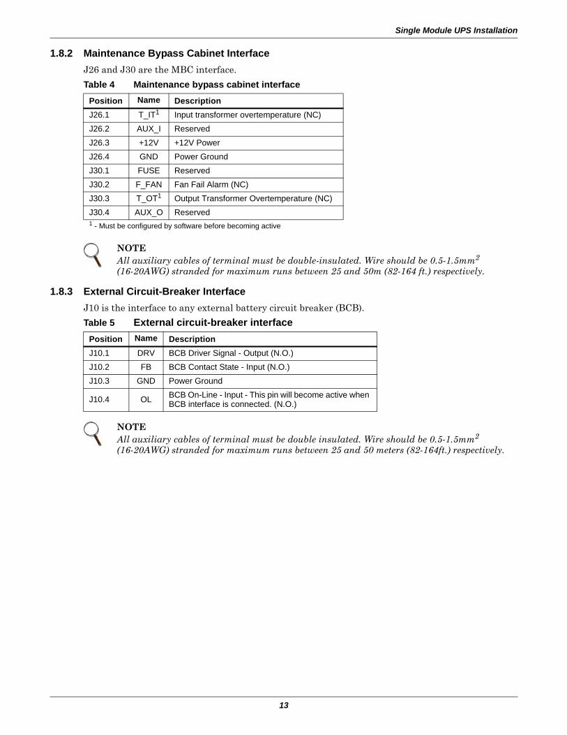
1.8.2 Maintenance Bypass Cabinet InterfaceJ26 and J30 are the MBC interface.
1.8.3 External Circuit-Breaker InterfaceJ10 is the interface to any external battery circuit breaker (BCB).
Table 4 Maintenance bypass cabinet interface
Position Name Description J26.1 T_IT1 Input transformer overtemperature (NC)
J26.2 AUX_I Reserved
J26.3 +12V +12V Power
J26.4 GND Power Ground
J30.1 FUSE Reserved
J30.2 F_FAN Fan Fail Alarm (NC)
J30.3 T_OT1 Output Transformer Overtemperature (NC)
J30.4 AUX_O Reserved1 - Must be configured by software before becoming active
NOTEAll auxiliary cables of terminal must be double-insulated. Wire should be 0.5-1.5mm2
(16-20AWG) stranded for maximum runs between 25 and 50m (82-164 ft.) respectively.
Table 5 External circuit-breaker interfacePosition Name Description J10.1 DRV BCB Driver Signal - Output (N.O.)
J10.2 FB BCB Contact State - Input (N.O.)
J10.3 GND Power Ground
J10.4 OL BCB On-Line - Input - This pin will become active when BCB interface is connected. (N.O.)
NOTEAll auxiliary cables of terminal must be double insulated. Wire should be 0.5-1.5mm2 (16-20AWG) stranded for maximum runs between 25 and 50 meters (82-164ft.) respectively.
Single Module UPS Installation
14
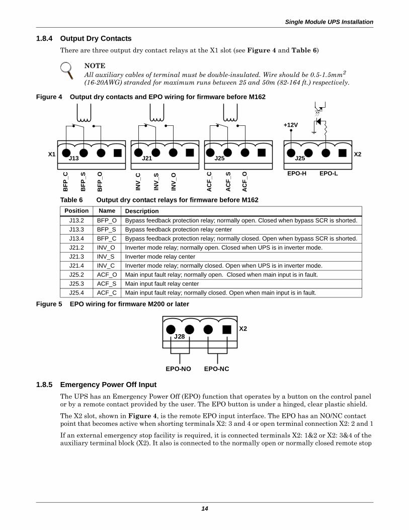
1.8.4 Output Dry ContactsThere are three output dry contact relays at the X1 slot (see Figure 4 and Table 6)
Figure 4 Output dry contacts and EPO wiring for firmware before M162
Figure 5 EPO wiring for firmware M200 or later
1.8.5 Emergency Power Off InputThe UPS has an Emergency Power Off (EPO) function that operates by a button on the control panel or by a remote contact provided by the user. The EPO button is under a hinged, clear plastic shield.
The X2 slot, shown in Figure 4, is the remote EPO input interface. The EPO has an NO/NC contact point that becomes active when shorting terminals X2: 3 and 4 or open terminal connection X2: 2 and 1
If an external emergency stop facility is required, it is connected terminals X2: 1&2 or X2: 3&4 of the auxiliary terminal block (X2). It also is connected to the normally open or normally closed remote stop
NOTEAll auxiliary cables of terminal must be double-insulated. Wire should be 0.5-1.5mm2
(16-20AWG) stranded for maximum runs between 25 and 50m (82-164 ft.) respectively.
Table 6 Output dry contact relays for firmware before M162Position Name Description
J13.2 BFP_O Bypass feedback protection relay; normally open. Closed when bypass SCR is shorted.J13.3 BFP_S Bypass feedback protection relay centerJ13.4 BFP_C Bypass feedback protection relay; normally closed. Open when bypass SCR is shorted.J21.2 INV_O Inverter mode relay; normally open. Closed when UPS is in inverter mode.J21.3 INV_S Inverter mode relay centerJ21.4 INV_C Inverter mode relay; normally closed. Open when UPS is in inverter mode.J25.2 ACF_O Main input fault relay; normally open. Closed when main input is in fault.J25.3 ACF_S Main input fault relay centerJ25.4 ACF_C Main input fault relay; normally closed. Open when main input is in fault.
EPO-LEPO-H
X2X1
BFP
_C
J21 J25 J25
BFP
_S
BFP
_O
INV_
O
INV_
S
INV_
C
AC
F_C
AC
F_S
AC
F_O
+12V
J13
J28X2
EPO-NO EPO-NC
Single Module UPS Installation
15
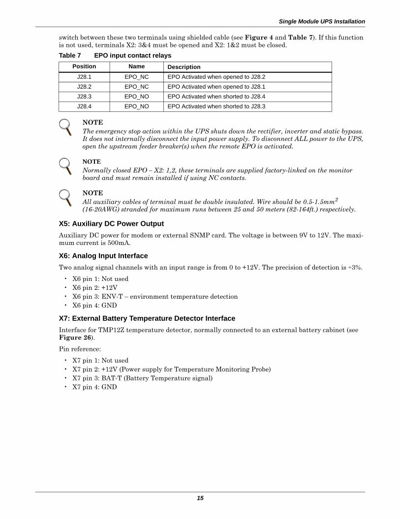
switch between these two terminals using shielded cable (see Figure 4 and Table 7). If this function is not used, terminals X2: 3&4 must be opened and X2: 1&2 must be closed.
X5: Auxiliary DC Power OutputAuxiliary DC power for modem or external SNMP card. The voltage is between 9V to 12V. The maxi-mum current is 500mA.
X6: Analog Input InterfaceTwo analog signal channels with an input range is from 0 to +12V. The precision of detection is ÷3%.
• X6 pin 1: Not used• X6 pin 2: +12V• X6 pin 3: ENV-T – environment temperature detection• X6 pin 4: GND
X7: External Battery Temperature Detector InterfaceInterface for TMP12Z temperature detector, normally connected to an external battery cabinet (see Figure 26).
Pin reference:
• X7 pin 1: Not used• X7 pin 2: +12V (Power supply for Temperature Monitoring Probe)• X7 pin 3: BAT-T (Battery Temperature signal)• X7 pin 4: GND
Table 7 EPO input contact relaysPosition Name Description
J28.1 EPO_NC EPO Activated when opened to J28.2
J28.2 EPO_NC EPO Activated when opened to J28.1
J28.3 EPO_NO EPO Activated when shorted to J28.4
J28.4 EPO_NO EPO Activated when shorted to J28.3
NOTEThe emergency stop action within the UPS shuts down the rectifier, inverter and static bypass. It does not internally disconnect the input power supply. To disconnect ALL power to the UPS, open the upstream feeder breaker(s) when the remote EPO is activated.
NOTENormally closed EPO – X2: 1,2, these terminals are supplied factory-linked on the monitor board and must remain installed if using NC contacts.
NOTEAll auxiliary cables of terminal must be double insulated. Wire should be 0.5-1.5mm2 (16-20AWG) stranded for maximum runs between 25 and 50 meters (82-164ft.) respectively.
Single Module UPS Installation
16
Serial Ports RS232-1 and RS232-2RS232-1 provides serial data and is intended for direct use with Liebert MultiLink monitoring and server shutdown software.
RS232-2 provides serial data and is intended for use by authorized commissioning and service person-nel.
These serial ports are shared with the optional Web browser, SNMP, ModBus and relay cards. Refer to Table 31 regarding compatibility of simultaneous use.
Intellislot Web Browser, SNMP, ModBus and Relay Cards Interface There are three interface slots available for optional Web browser, SNMP, ModBus and Relay cards as illustrated in 9.0 - Options—For Assembly Inside the UPS Cabinet.
1.8.6 External Bypass Switch InterlockEXT-Maint X3-1&2 on UPS Parallel Board M3 (leave open if no external bypass switch is used)
Provides external maintenance bypass interlock protection for the UPS. Short circuit means external bypass closed.
EXT-Out (X3-3&4) on UPS Parallel Board (leave shorted if no external output switch is used). Pro-vides external output interlock protection for paralleled UPS modules. Short circuit means external output switch closed.
NOTEUPS Parallel Board M3 is located behind protective covers accessible after opening the UPS front door—removal of this barrier requires the use of a tool and is restricted to service personnel.
NOTEJumper JP1 (located next to X3) needs to be removed for X3:3&4 to work properly.
Battery Installation
17
2.0 BATTERY INSTALLATION
2.1 IntroductionThe UPS battery bank consists of battery blocks connected in series to provide a D.C. string voltage as required by the UPS converter. The 'AUTONOMY TIME' (the time during which the battery can maintain supply to the load in the event of a mains failure) is limited by the ampere-hour capacity of the battery blocks and in some cases this results in several strings being connected in parallel.
The NX 30-40kVA has internal batteries, but longer run time is available by using an external bat-tery cabinet.
The battery cabinet will be supplied in one of the following forms:1. Complete installation, comprising the battery cabinet, batteries and protective device.2. Battery cabinets and protective device only—batteries supplied by others3. Battery cabinet only—batteries and circuit breaker supplied by others.
The battery bank may be disconnected from the UPS for maintenance or service. The circuit breaker can be switched ON or OFF manually and further battery isolation control is achieved through the use of either a battery circuit-breaker undervoltage coil or through an automatic contactor inside the UPS.
NOTE30kVA to 40kVA UPS models contain an internal battery compartment that can accommodate up to 42 blocks 24 Ah/12V batteries.
Battery Installation
18
2.2 SafetySpecial care should be taken when working with the batteries associated with the Liebert NX UPS system. When all the cells are connected together, the battery terminal voltage is potentially hazard-ous. The battery installation must be segregated from all but appropriately qualified maintenance personnel by locating the cells in a key-lockable cabinet or in a purpose-designed, dedicated battery room.
2.3 Battery Cabinet2.3.1 Introduction
This cabinet can also be used in conjunction additional cabinets, to provide the necessary accommoda-tion required by the larger cells associated with system’s having a long autonomy time.
Where two (or more) cabinets are used they are positioned alongside each other and secured and bonded together. If the cabinet(s) is located immediately adjacent to the main UPS equipment the two units are bolted together.
NOTEFull safety instructions concerning the use and maintenance of UPS batteries are provided in the appropriate battery manufacturers manuals. The battery safety information contained in this section relates to key considerations that must be taken into account during the installation design process and might affect the design outcome depending on localised conditions.
! WARNINGHazardous battery voltage present behind covers
No user-serviceable parts are located behind covers that require a tool for their removal. Only qualified service personnel are authorised to remove such covers.
When using internal batteries in 30 and 40kVA units, the batteries are always connected through power fuses to the UPS and to the segregated terminal bars available for connection to an external battery.
Isolate any internal battery connections before attempting to access the segregated terminal bars available for connection to an external battery.
The following general battery safety precautions and warnings should be observed at all times:
• A battery can present risk of electric shock or burn from high- short-circuit currents.• The full nominal string voltage, when the battery blocks are interconnected, is 480VDC,
which is hazardous • Only qualified personnel should install or service batteries.• Eye protection should be worn to prevent injury from electrical arcs.• Remove rings, watches, necklaces, bracelets and all other metal objects.• Use only tools with insulated handles.• Wear rubber gloves and a rubber apron when handling batteries.• If a battery leaks electrolyte or is otherwise damaged, it should be placed in a container
resistant to sulfuric acid and disposed of in accordance with local regulations.• If electrolyte comes into contact with the skin the affected area should be washed immedi-
ately with plenty of clean water.• Batteries must always be disposed of according to local environmental laws.• When replacing batteries, use the same number and type that were originally fitted.• Disconnect charging source before connecting or disconnecting battery terminals.• Determine whether the battery is inadvertently grounded. If it is inadvertently grounded,
remove the source of the ground. Contact with any part of a grounded battery can result in electrical shock.
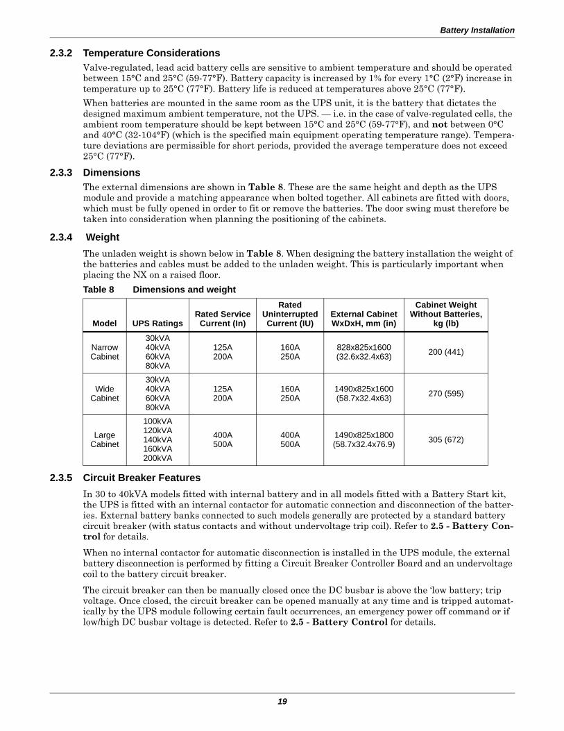
Battery Installation
19
2.3.2 Temperature ConsiderationsValve-regulated, lead acid battery cells are sensitive to ambient temperature and should be operated between 15°C and 25°C (59-77°F). Battery capacity is increased by 1% for every 1°C (2°F) increase in temperature up to 25°C (77°F). Battery life is reduced at temperatures above 25°C (77°F).
When batteries are mounted in the same room as the UPS unit, it is the battery that dictates the designed maximum ambient temperature, not the UPS. — i.e. in the case of valve-regulated cells, the ambient room temperature should be kept between 15°C and 25°C (59-77°F), and not between 0°C and 40°C (32-104°F) (which is the specified main equipment operating temperature range). Tempera-ture deviations are permissible for short periods, provided the average temperature does not exceed 25°C (77°F).
2.3.3 DimensionsThe external dimensions are shown in Table 8. These are the same height and depth as the UPS module and provide a matching appearance when bolted together. All cabinets are fitted with doors, which must be fully opened in order to fit or remove the batteries. The door swing must therefore be taken into consideration when planning the positioning of the cabinets.
2.3.4 WeightThe unladen weight is shown below in Table 8. When designing the battery installation the weight of the batteries and cables must be added to the unladen weight. This is particularly important when placing the NX on a raised floor.
2.3.5 Circuit Breaker FeaturesIn 30 to 40kVA models fitted with internal battery and in all models fitted with a Battery Start kit, the UPS is fitted with an internal contactor for automatic connection and disconnection of the batter-ies. External battery banks connected to such models generally are protected by a standard battery circuit breaker (with status contacts and without undervoltage trip coil). Refer to 2.5 - Battery Con-trol for details.
When no internal contactor for automatic disconnection is installed in the UPS module, the external battery disconnection is performed by fitting a Circuit Breaker Controller Board and an undervoltage coil to the battery circuit breaker.
The circuit breaker can then be manually closed once the DC busbar is above the ‘low battery; trip voltage. Once closed, the circuit breaker can be opened manually at any time and is tripped automat-ically by the UPS module following certain fault occurrences, an emergency power off command or if low/high DC busbar voltage is detected. Refer to 2.5 - Battery Control for details.
Table 8 Dimensions and weight
Model UPS RatingsRated Service
Current (In)
RatedUninterruptedCurrent (IU)
External CabinetWxDxH, mm (in)
Cabinet WeightWithout Batteries,
kg (lb)
NarrowCabinet
30kVA40kVA60kVA80kVA
125A200A
160A250A
828x825x1600(32.6x32.4x63) 200 (441)
WideCabinet
30kVA40kVA60kVA80kVA
125A200A
160A250A
1490x825x1600(58.7x32.4x63) 270 (595)
LargeCabinet
100kVA120kVA140kVA160kVA200kVA
400A500A
400A500A
1490x825x1800(58.7x32.4x76.9) 305 (672)
Battery Installation
20
2.3.6 Moving the Battery Cabinets
Ensure that the weight is within the designated surface weight loading of any handling equipment. See Table 8 for weight details.
Battery cabinets can be handled by means of a fork lift or similar equipment.
2.3.7 Cable EntryCables enter the battery cabinet from either the top or the bottom. Cable entry is made possible by removing a blanking piece fitted at the bottom to reveal the cable entry hole.
!
WARNING Ensure any lifting equipment used in moving the cabinet has sufficient lifting capacity.
NOTECare must be taken when maneuvering units fitted with batteries. Keep such moves to a minimum.
When the equipment has been finally positioned ensure the adjustable feet are set so that the battery cabinet will remain stationary and stable.
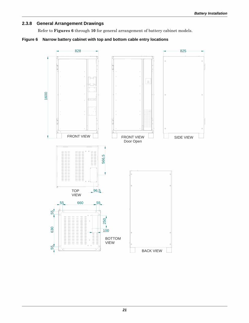
Battery Installation
21
2.3.8 General Arrangement Drawings Refer to Figures 6 through 10 for general arrangement of battery cabinet models.
Figure 6 Narrow battery cabinet with top and bottom cable entry locations
FRONT VIEW FRONT VIEWDoor Open
SIDE VIEW
BOTTOMVIEW
BACK VIEW
TOPVIEW
1600
5563
055
55
250
100
566,
5
96,5
828
660 55
825
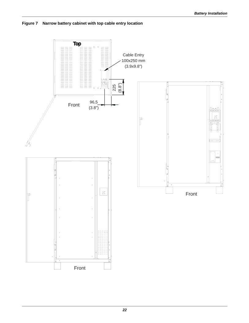
Battery Installation
22
Figure 7 Narrow battery cabinet with top cable entry location
Cable Entry100x250 mm
(3.9x9.8")
Front
TopTop
Front
Front
96,5(3.8")
225
(8.8
")
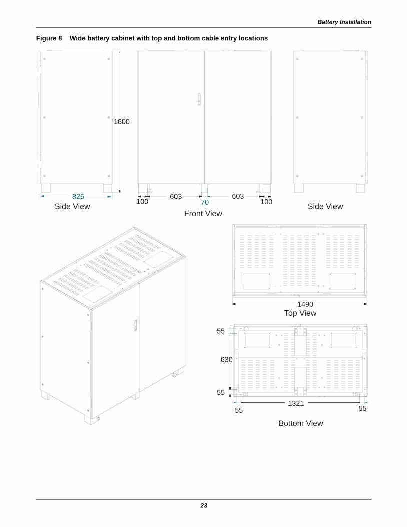
Battery Installation
23
Figure 8 Wide battery cabinet with top and bottom cable entry locations
1600
1490
100 100603 603
70
5555
55
630
55
1321
Side View Side View
Top View
Front View
Bottom View
825
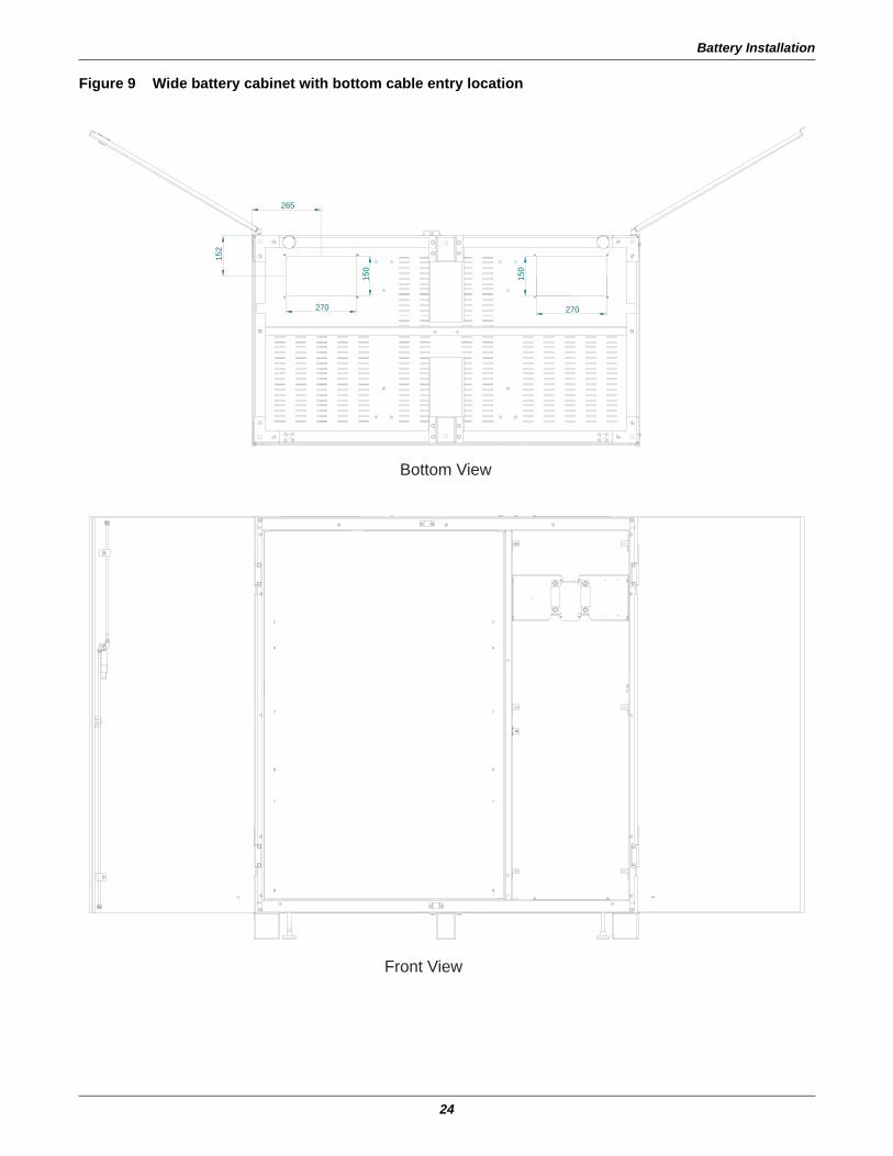
Battery Installation
24
Figure 9 Wide battery cabinet with bottom cable entry location
150
152
270
265
270
150
Bottom View
Front View
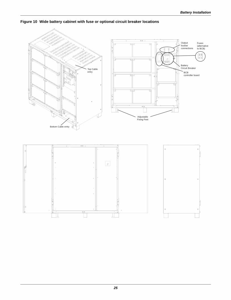
Battery Installation
25
Figure 10 Wide battery cabinet with fuse or optional circuit breaker locations
Bottom Cable entry
Adjustable Fixing Feet
BCBcontroller board
BatteryCircuit Breaker
Outputbusbar connections
Fuses(alternativeto BCB)
Top Cableentry
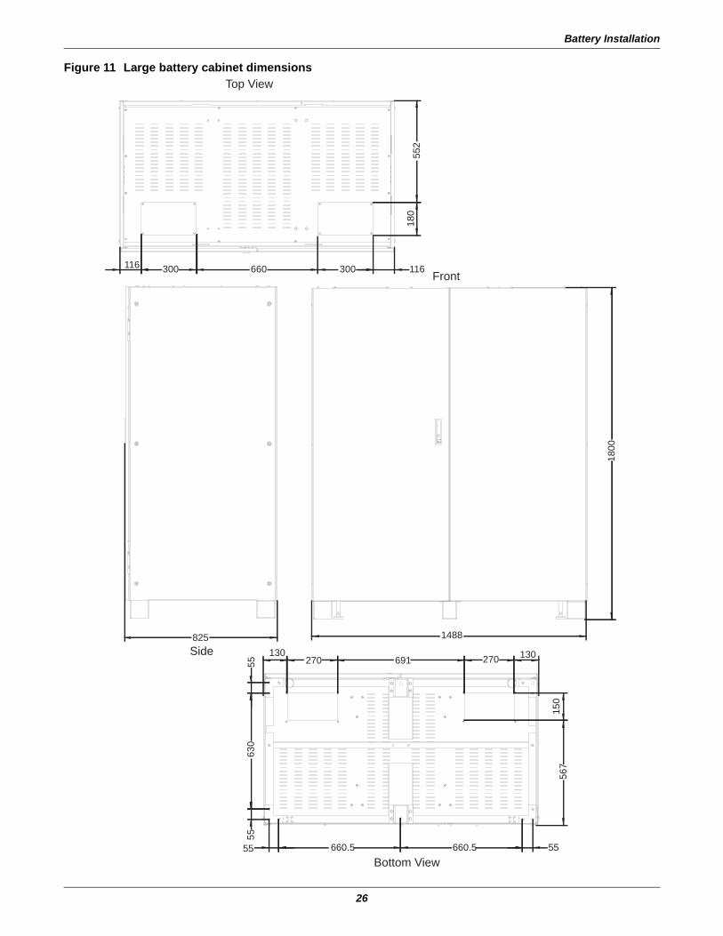
Battery Installation
26
Figure 11 Large battery cabinet dimensions
1488
1800
825
116 300 660 300 116
552
180
5563
055
55 660.5 660.5 55
130270 691 270 130
567
150
Bottom View
Top View
Front
Side
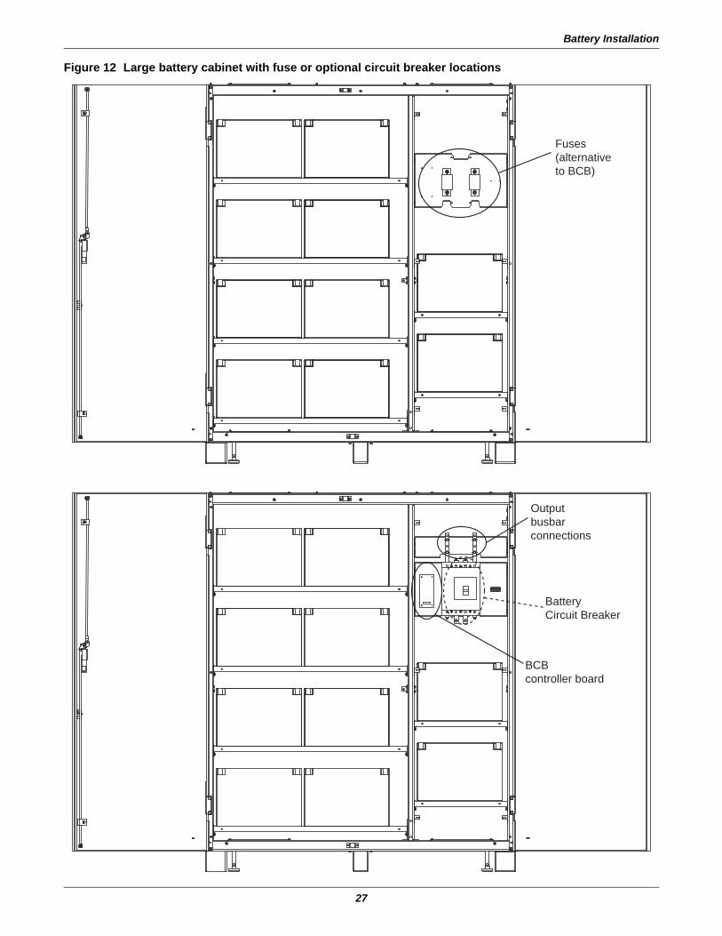
Battery Installation
27
Figure 12 Large battery cabinet with fuse or optional circuit breaker locations
BatteryCircuit Breaker
BCBcontroller board
Outputbusbar connections
Fuses(alternativeto BCB)
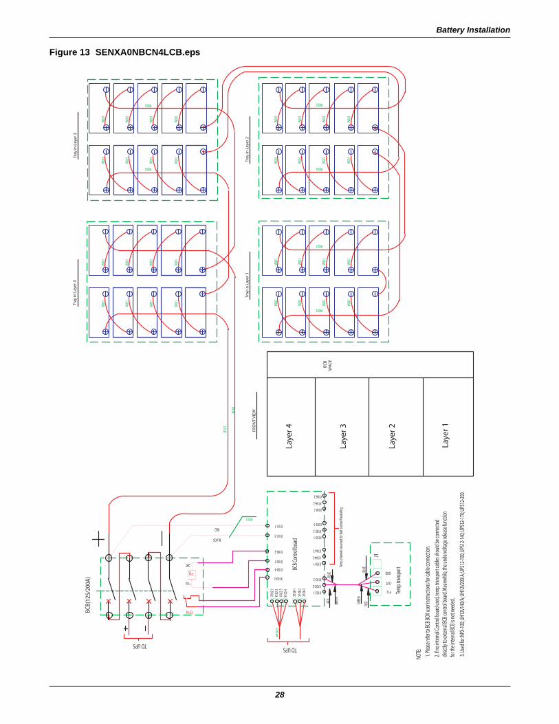
Battery Installation
28
Figure 13 SENXA0NBCN4LCB.eps
W00
1
W00
1
W00
1W
001
W00
1
W00
1
W00
1W
001
W002
W002
W00
1
W00
1
W00
1
W00
1W
001
W00
1
W00
1
W00
1
W00
1
W00
1
W00
1
W00
1W
001
W00
1
W00
1
W00
1W
001
W00
1
W00
1
W00
1W
001
W00
1
W00
1
W00
1
W002
W002
W002
W002
W10
1
W10
2
W301
W30
2
BC
B
Laye
r 1
Laye
r 2
Laye
r 3
SPA
CE
FRO
NT
VIE
W
Laye
r 4
TO UPS
BCB(
125/
200A
)
Tray
in L
ayer
1Tr
ay in
Lay
er 2
Tray
in L
ayer
4Tr
ay in
Lay
er 3
TO UPS
3. Us
ed fo
r: NPX
-100;
UH12
V140
/A; U
H12V
200/
A; UP
S12-1
00; U
PS12
-140;
UPS1
2-170
; UPS
12-20
0.
1. Ple
ase r
efer t
o BCB
BOX u
ser in
struc
tions
for c
able
conn
ectio
n.
2. If n
o int
ernal
Cont
rol b
oard
used
, tem
p. tra
nspo
rt ca
bles s
hould
be co
nnec
teddir
ectly
to ex
terna
l BCB
cont
rol b
oard
. Mea
nwhil
e, th
e und
ervo
ltage
relea
se fu
nctio
nfor
the i
ntern
al BC
B is n
ot ne
eded
.
NOTE
:
Tem
p. tra
nspo
rtTem
p. ch
anne
ls res
erve
d for
Batt.
cabin
et Pa
rallel
ing
OUT
P12
RED
GND
J1
BLUE
GREE
N
RED
GREE
N
BLUE
X105-2
BCB C
ontro
l boa
rd
X102
-4
X108
-3
X103-2
X103-1
X108
-1X1
08-2
X104-2
X104-1
X103-3
X105-1
X104-3
X102
-1X1
02-2
X102
-3
X100-4
X100-1
X100-3
X101-3
X100-2
X106-2
X106-1
X105-3
X106-3
X101-1RED
BLACKP
N.O.
N
V<
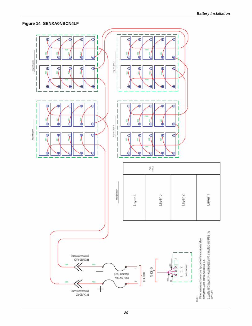
Battery Installation
29
Figure 14 SENXA0NBCN4LF
W00
1
W00
1
W00
1
W002
W00
1
W002
W00
1
W00
1
W00
1W
001
W00
1
W00
1
W00
1
W00
1W
001
W00
1
W00
1
W00
1
W002
W002
W00
1
W00
1
W00
1
W00
1W
001
W00
1
W00
1
W00
1
W002
W002
W00
1
W00
1
W00
1
W00
1W
001
W00
1
W00
1
W00
1W004
W006W005
W003
FRO
NT
VIE
W
TO BC
B BOX
TO BC
B BOX
BC
BSP
AC
E
Tray
in L
ayer
1Tr
ay in
Lay
er 2
Tray
in L
ayer
4Tr
ay in
Lay
er 3
Laye
r 4
Laye
r 3
Laye
r 2
Laye
r 1
J1
2. Us
ed fo
r: NPX
-100;
UH12
V140
/A; U
H12V
200/
A; UP
S12-1
00; U
PS12
-140;
UPS1
2-170
; UP
S12-2
00.
1. W
hen f
uses
are u
sed f
or ov
ercur
rent p
rotec
tion,
the t
emp.s
ignals
shall
go
direc
tly to
the c
ontro
l boa
rd in
exter
nal B
CB BO
X.
NOTE
:
OUT
Tem
p. tra
nspo
rt
P12
GND
GREE
N
RED
BLUE
FWP-120A/200A(Bussmann Fuses)
PP120/180-RED(Anderson connector)
PP120/180-BLACK(Anderson connector)
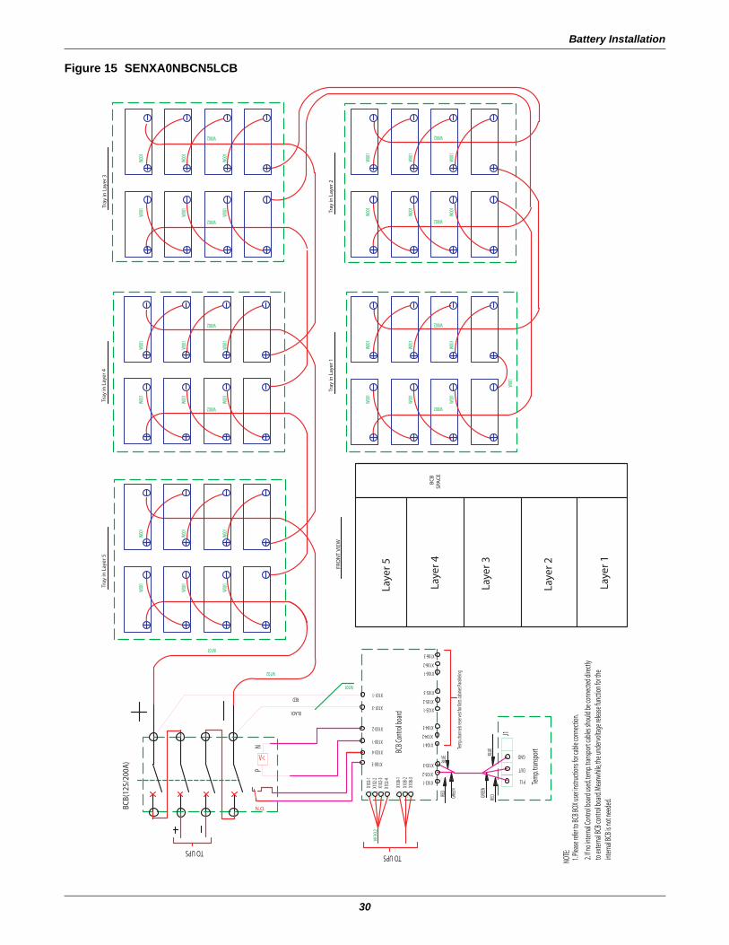
Battery Installation
30
Figure 15 SENXA0NBCN5LCB
W00
1
W00
1
W00
1
W002
W00
1
W002
W00
1
W00
1
W002
W00
1
W00
1
W00
1W
001
W00
1
W00
1
W002
W002
W00
1
W00
1
W00
1W
001
W00
1
W00
1
W002
W002
W00
1
W00
1
W00
1W
001
W00
1
W00
1
W002
W00
1
W00
1
W00
1
W00
1W
001
W00
1
W00
1
W102
W101
W301
W30
2
BC
BSP
AC
E
BCB(
125/
200A
)
TO UPS
FRO
NT
VIE
WTr
ay in
Lay
er 1
Tray
in L
ayer
5Tr
ay in
Lay
er 4
Tray
in L
ayer
2
Tray
in L
ayer
3
TO UPS
Laye
r 4
Laye
r 3
Laye
r 2
Laye
r 1
Laye
r 5
2. If n
o int
ernal
Cont
rol b
oard
used
, tem
p. tra
nspo
rt ca
bles s
hould
be co
nnec
ted di
rectly
to
exter
nal B
CB co
ntro
l boa
rd. M
eanw
hile,
the u
nder
volta
ge re
lease
func
tion f
or th
e int
ernal
BCB i
s not
need
ed.
1. Ple
ase r
efer t
o BCB
BOX u
ser in
struc
tions
for c
able
conn
ectio
n. NO
TE:
N.O.
BLACK
RED
NP
V<
X100-4
X100-3
X101-3
X101-1
X100-2
X100-1
Tem
p. ch
anne
ls res
erve
d for
Batt.
cabin
et Pa
rallel
ing
P12
Tem
p. tra
nspo
rt
REDGR
EEN
OUT
GNDBLUE
J1
X102
-3
X108
-2X1
08-1
X108
-3
X102
-4 X10³-1
GREE
N
RED
X106-3
X105-3
X106-1
X106-2
X104-3
X105-1
X103-3
X104-1
X104-2
X103-2
X105-2
BLUE
BCB C
ontro
l boa
rd
X102
-2X1
02-1
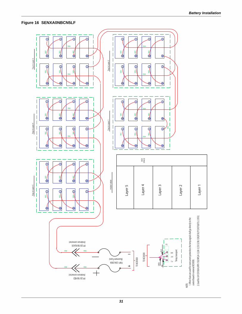
Battery Installation
31
Figure 16 SENXA0NBCN5LF
W00
1
W00
1
W00
1
W006
W004
W002
W002
W00
1
W00
1
W00
1
W00
1
W00
1
W00
1
W00
1
W00
1
W00
1
W00
1
W00
1
W00
1
W00
1
W00
1
W00
1
W002
W002 W00
1
W00
1
W00
1
W002
W002
W00
1
W00
1
W00
1W
001
W00
1
W00
1
W002
W002
W00
1
W00
1
W00
1
W00
1
W005
W003
TO BC
B BOX
TO BC
B BOX
FRO
NT
VIE
W
SPA
CE
BC
B
Tray
in L
ayer
1
Tray
in L
ayer
5Tr
ay in
Lay
er 4
Tray
in L
ayer
2
Tray
in L
ayer
3
Laye
r 5
Laye
r 4
Laye
r 3
Laye
r 2
Laye
r 1
1. W
hen f
uses
are u
sed f
or ov
ercur
rent p
rotec
tion,
the t
emp.s
ignals
shall
go di
rectly
to th
e co
ntro
l boa
rd in
exter
nal B
CB BO
X.
NOTE
:
J1
Tem
p. tra
nspo
rt
P12
OUT
GND
GREE
N
RED
BLUE
FWP-120A/200A(Bussmann Fuses)
PP120/180-RED(Anderson connector)
PP120/180-BLACK(Anderson connector)
2. Us
ed fo
r: UH1
2V10
0/A;
NPX-
150;
NPL2
4-12,3
8-12;
S512
/38;
12XL
B150
; P12
V570
,875;
L12V
32.
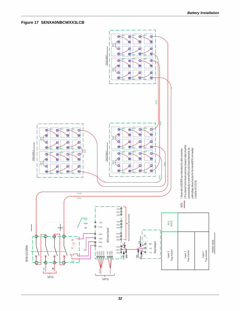
Battery Installation
32
Figure 17 SENXA0NBCWXX3LCB
W00
2
W00
2W
002
W301
W101
W102
W30
2
W001
W001
W001
W001
W001
W001
W001
W001
W001
W001
W00
1
W001W001
W00
1
W001
W001
W001W001
W001
W001
W001W001
W001
W001
W001
W00
1
W001
W00
1
W001
W001
W001W001
W001
W001
W001W001
W001
W001
W001
W00
1
W001
W00
1
W00
2
W00
1
Tray
in L
ayer
1
Tray
mas
ter
Laye
r 1
Laye
r 3
Laye
r 2Tr
ay m
aste
r
FRO
NT
VIE
W
SPA
CE
BC
B
TO UPS
Tray
in L
ayer
2
BCB(
125/
200A
)
Tray
in L
ayer
3TO UPS
Tray
mas
ter
3. Us
ed fo
r: A41
2/32
G6.
2. If n
o int
ernal
Cont
rol b
oard
used
, tem
p. tra
nspo
rt ca
bles s
hould
be
conn
ected
direc
tly to
exter
nal B
CB co
ntro
l boa
rd. M
eanw
hile,
the
unde
rvolta
ge re
lease
func
tion f
or th
e int
ernal
BCB i
s not
need
ed.
1. Ple
ase r
efer t
o BCB
BOX u
ser in
struc
tions
for c
able
conn
ectio
n. NO
TE:
N.O.
V<
RED
BLACK
NP
X102
-1
X100-4
X100-3
X101-3
X100-2
Tem
p. ch
anne
ls res
erve
d for
Batt.
cabin
et Pa
rallel
ing
BLUE
Tem
p. tra
nspo
rt
GREE
N
RED
P12
OUT
GREE
N
RED
X103-1
X103-2
X103-3
X102
-2
X102
-4
X108
-3
X108
-1X1
08-2
X102
-3
GNDBLUE
J1
BCB C
ontro
l boa
rd
X104-1
X104-2
X104-3
X100-1
X105-2
X105-1
X105-3X101-1
X106-2
X106-1
X106-3
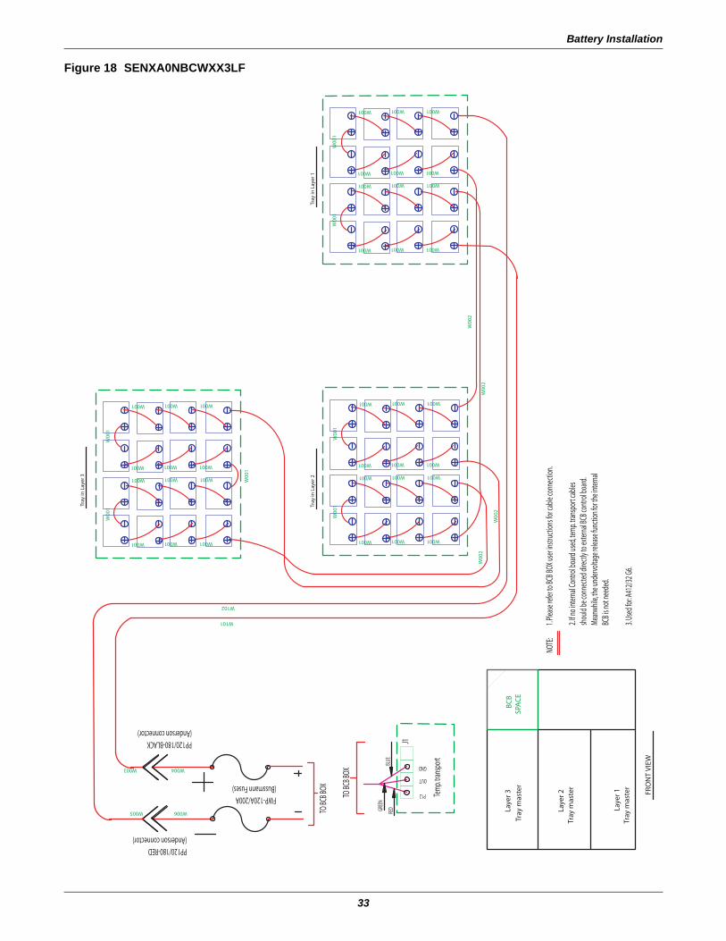
Battery Installation
33
Figure 18 SENXA0NBCWXX3LF
W00
2
W00
2W
002
W101
W102
W001
W001
W001
W001
W001
W001
W001
W001
W001
W001
W00
1
W001W001
W00
1
W001
W001
W001W001
W001
W001
W001W001
W001
W001
W001
W00
1
W001
W00
1
W001
W001
W001W001
W001
W001
W001W001
W001
W001
W001
W00
1
W001
W00
1
W00
2
W00
1
W006
W004
W005
W003
Tray
in L
ayer
1
Tray
mas
ter
Laye
r 1
Laye
r 3
Laye
r 2Tr
ay m
aste
r
FRO
NT
VIE
W
SPA
CE
BC
B
Tray
in L
ayer
2
Tray
in L
ayer
3
Tray
mas
ter
TO BC
B BOX
TO BC
B BOX
3. Us
ed fo
r: A41
2/32
G6.
2. If n
o int
ernal
Cont
rol b
oard
used
, tem
p. tra
nspo
rt ca
bles
shou
ld be
conn
ected
direc
tly to
exter
nal B
CB co
ntro
l boa
rd.
Mean
while
, the u
nder
volta
ge re
lease
func
tion f
or th
e int
ernal
BCB i
s not
need
ed.
1. Ple
ase r
efer t
o BCB
BOX u
ser in
struc
tions
for c
able
conn
ectio
n. NO
TE:
OUT
P12
GND
Tem
p. tra
nspo
rt
J1
REDGR
EEN
BLUE
PP120/180-RED(Anderson connector)
PP120/180-BLACK(Anderson connector)
FWP-120A/200A(Bussmann Fuses)
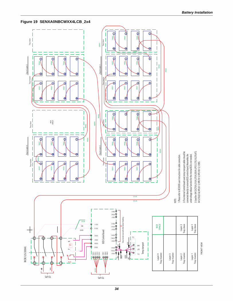
Battery Installation
34
Figure 19 SENXA0NBCWXX4LCB_2x4
W102
W101
W00
1
W301
W00
1
W00
1
W00
1
W00
1W
001
W00
1
W00
1
W003
W00
1
W00
1
W00
1
W30
2
W00
1
W00
1W
001
W00
1
W00
1
W00
1
W00
1
W00
1W
001
W00
1
W00
1
W00
1
W00
1
W00
1W
001
W00
1
W00
1
W00
1
W00
1
W00
4
W00
2
W00
4W
002
W00
4
W00
3
W00
3
W00
2W
004
Tray
in L
ayer
3
Tray
in L
ayer
1
Tray
mas
ter
Laye
r 1
Laye
r 3Tr
ay m
aste
r
Tray
mas
ter
Laye
r 4
Laye
r 2Tr
ay m
aste
r
Tray
sla
ve
FRO
NT
VIE
W
Laye
r 1
Laye
r 2Tr
ay s
lave
SPA
CE
BC
B
BCB(
125/
200A
)TO UPS
Tray
in L
ayer
2
Tray
mas
ter
SPA
CE
BC
B
Tray
sla
ve
Tray
in L
ayer
4
TO UPS
Tray
sla
veTr
ay m
aste
r
Tray
sla
veTr
ay m
aste
r
Tray
sla
veTr
ay m
aste
r
3. Us
ed fo
r: UH1
2V27
0/A,3
10/A
,370/
A,500
/A; U
PS12
-270,3
10,37
0,475
; A4
12/5
0,65 G
6; NP
L65-1
2; NP
L78-1
2; NP
L100
-12; 1
290S
.
2. If n
o int
ernal
Cont
rol b
oard
used
, tem
p. tra
nspo
rt ca
bles s
hould
be
conn
ected
direc
tly to
exter
nal B
CB co
ntro
l boa
rd. M
eanw
hile,
the
unde
rvolta
ge re
lease
func
tion f
or th
e int
ernal
BCB i
s not
need
ed.
1. Ple
ase r
efer t
o BCB
BOX u
ser in
struc
tions
for c
able
conn
ectio
n.
NOTE
:
N.O.
V<
RED
BLACKN
P
BCB C
ontro
l boa
rd
GND
OUT
P12 Tem
p. tra
nspo
rt
X104-2
Tem
p. ch
anne
ls res
erve
d for
Batt.
cabin
et Pa
rallel
ing
REDGR
EEN
GREE
N
BLUE
X104-1
X103-3
X103-1
X103-2
RED
BLUE
X108
-2X1
08-3
J1
X106-1
X105-3
X105-2
X105-1
X104-3
X106-3
X106-2
X100-4
X100-3
X100-1
X102
-2
X102
-4
X108
-1
X102
-3
X102
-1
X101-3
X101-1
X100-2
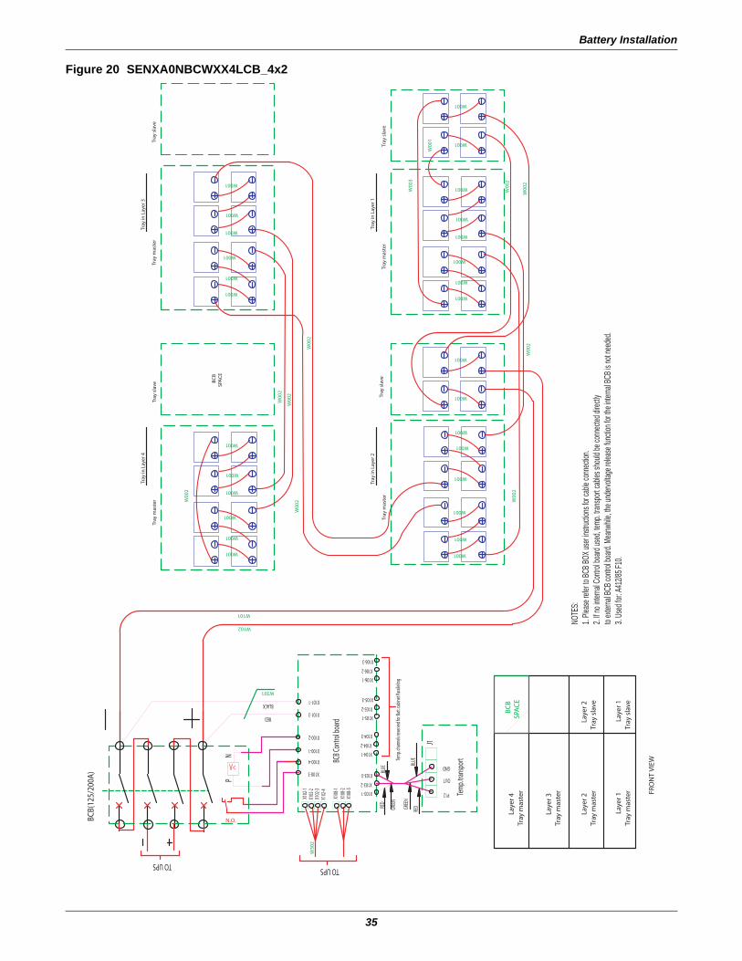
Battery Installation
35
Figure 20 SENXA0NBCWXX4LCB_4x2
W301
W101
W102
W00
2
W001
W001
W001
W001
W001
W001
W00
3
W001
W001
W00
1
W00
2
W00
2
W00
2
W00
2
W00
2
W30
2
W001
W001
W001
W001
W001
W001
W001
W001
W001
W001
W001
W001
W001
W001
W00
2
W001
W001
W001
W001
W001
W001
W00
2
W00
2
Tray
in L
ayer
1
Tray
in L
ayer
3
FRO
NT
VIE
W
BCB(
125/
200A
)TO UPS
Tray
in L
ayer
2
SPA
CE
BC
B
Tray
in L
ayer
4
TO UPS
Tray
mas
ter
Tray
mas
ter
Laye
r 1
Tray
mas
ter
Laye
r 2
Tray
sla
veLa
yer 1
Tray
sla
veLa
yer 2
Tray
mas
ter
Laye
r 3
Laye
r 4B
CB
SPA
CE
Tray
mas
ter
Tray
sla
veTr
ay s
lave
Tray
mas
ter
Tray
sla
veTr
ay m
aste
rTr
ay m
aste
rTr
ay s
lave
N.O.
V<
BLACK
RED
PN
BLUE
Tem
p. tra
nspo
rt
P12
OUT
GREE
N
RED
X108
-3
GREE
N
RED
X103-2
X103-1
X103-3
X102
-2X1
02-3
X102
-4
X108
-2X1
08-1
X102
-1
X100-3
Tem
p. ch
anne
ls res
erve
d for
Batt.
cabin
et Pa
rallel
ing
GND
J1
BLUE
X101-3
BCB C
ontro
l boa
rd
X104-2
X104-1
X104-3
X105-1
X100-4
X100-1
X100-2
X105-3
X105-2
X106-1
X106-3
X106-2
X101-1
NOTE
S:1.
Pleas
e refe
r to BC
B BOX
user
instru
ctions
for c
able
conn
ectio
n. 2.
If no i
nterna
l Con
trol b
oard
used
, temp
. tran
sport
cable
s sho
uld be
conn
ected
direc
tlyto
exter
nal B
CB co
ntrol
board
. Mea
nwhile
, the u
nderv
oltag
e rele
ase f
unctio
n for
the in
terna
l BCB
is no
t nee
ded.
3. Us
ed fo
r: A41
2/85 F
10.
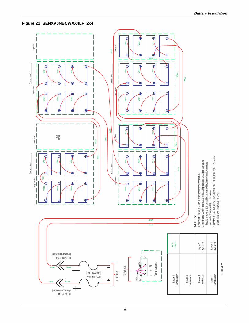
Battery Installation
36
Figure 21 SENXA0NBCWXX4LF_2x4
W102
W101
W006
W004
W005
W003
W00
4W
002
W00
1
W00
1
W00
1W
001
W00
1
W00
3W00
4W00
1
W00
1W
001
W00
1
W003
W00
1
W00
1
W00
4
W00
1W
001
W00
1
W00
2
W00
4
W00
1
W00
2
W00
1
W00
1W
001
W00
1
W00
3
W00
1W
001
W00
1
W00
1W
001
W00
1
W00
1W
001
W00
1W
001
W00
1
Tray
mas
ter
Laye
r 1
Laye
r 3Tr
ay m
aste
r
Tray
mas
ter
Laye
r 4
Laye
r 2Tr
ay m
aste
r
Tray
sla
ve
FRO
NT
VIE
W
Laye
r 1
Laye
r 2Tr
ay s
lave
SPA
CE
BC
B
TO BC
B BOX
TO BC
B BOX
Tray
in L
ayer
2
Tray
mas
ter
Tray
sla
ve
Tray
in L
ayer
1
Tray
mas
ter
Tray
sla
ve
Tray
in L
ayer
4
Tray
mas
ter
SPA
CE
BC
B
Tray
sla
ve
Tray
in L
ayer
3
Tray
mas
ter
Tray
sla
ve
NO
TES
:1.
Pleas
e refe
r to B
CB BO
X use
r instr
uctio
ns fo
r cab
le co
nnec
tion.
2. If n
o int
ernal
Cont
rol b
oard
used
, tem
p. tra
nspo
rt ca
bles s
hould
be co
nnec
ted
direc
tly to
exter
nal B
CB co
ntro
l boa
rd. M
eanw
hile,
the u
nder
volta
ge re
lease
func
tion f
or th
e int
ernal
BCB i
s not
need
ed.
3. Us
ed fo
r: UH1
2V27
0/A,3
10/A
,370/
A,500
/A; U
PS12
-270,3
10,37
0,475
; A41
2/50
,65 G
6;
NPL6
5-12;
NPL7
8-12;
NPL1
00-12
; 129
0S.
GND
OUT
P12 Tem
p. tra
nspo
rt
J1
BLUE
REDGR
EEN
PP120/180-BLACK(Anderson connector)
PP120/180-RED(Anderson connector)
FWP-120A/200A(Bussmann Fuses)
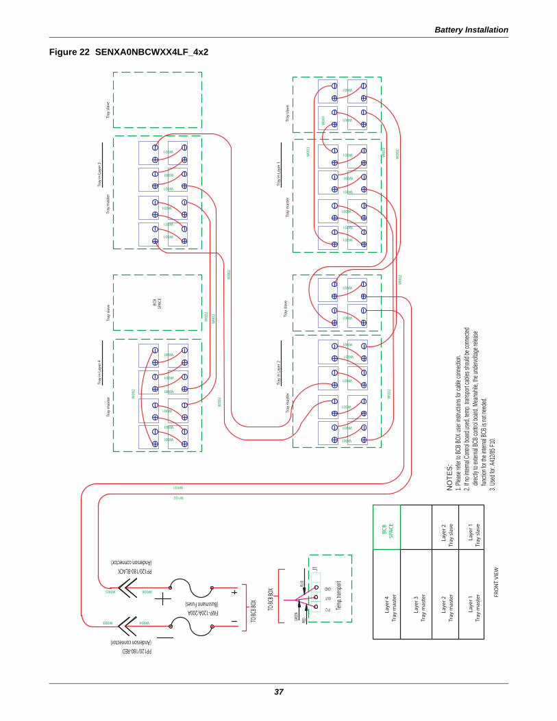
Battery Installation
37
Figure 22 SENXA0NBCWXX4LF_4x2
W101
W102
W00
2
W001
W001
W001
W001
W001
W001
W00
3
W001
W001
W00
1
W00
2
W00
2
W00
2
W00
2
W00
2
W001
W001
W001
W001
W001
W001
W001
W001
W001
W001
W001
W001
W001
W001
W00
2
W001
W001
W001
W001
W001
W001
W00
2
W00
2
W006
W004
W005
W003
Tray
in L
ayer
1
Tray
in L
ayer
3
FRO
NT
VIE
W
Tray
in L
ayer
2
SPA
CE
BC
B
Tray
in L
ayer
4
Tray
mas
ter
Tray
mas
ter
Laye
r 1
Tray
mas
ter
Laye
r 2
Tray
sla
veLa
yer 1
Tray
sla
veLa
yer 2
Tray
mas
ter
Laye
r 3
Laye
r 4B
CB
SPA
CE
Tray
mas
ter
Tray
sla
veTr
ay s
lave
Tray
mas
ter
Tray
sla
veTr
ay m
aste
rTr
ay m
aste
rTr
ay s
lave
TO BC
B BOX
TO BC
B BOX
J1
OUT
GND
Tem
p. tra
nspo
rt
P12
REDGR
EEN
BLUE
PP120/180-RED(Anderson connector)
PP120/180-BLACK(Anderson connector)
FWP-120A/200A(Bussmann Fuses)
NO
TES
:1.
Pleas
e refe
r to BC
B BOX
user
instru
ctions
for c
able
conn
ectio
n.2.
If no i
nterna
l Con
trol b
oard
used
, temp
. tran
sport
cable
s sho
uld be
conn
ected
dir
ectly
to ex
terna
l BCB
contr
ol bo
ard. M
eanw
hile, th
e und
ervolt
age r
eleas
e
functio
n for
the in
terna
l BCB
is no
t nee
ded.
3. Us
ed fo
r: A41
2/85 F
10.
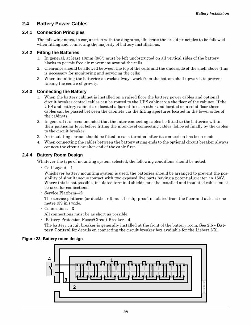
Battery Installation
38
2.4 Battery Power Cables
2.4.1 Connection PrinciplesThe following notes, in conjunction with the diagrams, illustrate the broad principles to be followed when fitting and connecting the majority of battery installations.
2.4.2 Fitting the Batteries1. In general, at least 10mm (3/8") must be left unobstructed on all vertical sides of the battery
blocks to permit free air movement around the cells. 2. Clearance should be allowed between the top of the cells and the underside of the shelf above (this
is necessary for monitoring and servicing the cells).3. When installing the batteries on racks always work from the bottom shelf upwards to prevent
raising the centre of gravity.
2.4.3 Connecting the Battery1. When the battery cabinet is installed on a raised floor the battery power cables and optional
circuit breaker control cables can be routed to the UPS cabinet via the floor of the cabinet. If the UPS and battery cabinet are located adjacent to each other and located on a solid floor these cables can be passed between the cabinets via the lifting apertures located in the lower sides of the cabinets.
2. In general it is recommended that the inter-connecting cables be fitted to the batteries within their particular level before fitting the inter-level connecting cables, followed finally by the cables to the circuit breaker.
3. An insulating shroud should be fitted to each terminal after its connection has been made.4. When connecting the cables between the battery string ends to the optional circuit breaker always
connect the circuit breaker end of the cable first.
2.4.4 Battery Room DesignWhatever the type of mounting system selected, the following conditions should be noted:
• Cell Layout—1Whichever battery mounting system is used, the batteries should be arranged to prevent the pos-sibility of simultaneous contact with two exposed live parts having a potential greater an 150V. Where this is not possible, insulated terminal shields must be installed and insulated cables must be used for connections.
• Service Platform—2The service platform (or duckboard) must be slip-proof, insulated from the floor and at least one metre (39 in.) wide.
• Connections—3All connections must be as short as possible.
• Battery Protection Fuses/Circuit Breaker—4The battery circuit breaker is generally installed at the front of the battery room. See 2.5 - Bat-tery Control for details on connecting the circuit breaker box available for the Liebert NX.
Figure 23 Battery room design
1
23
4
Battery Installation
39
2.5 Battery ControlThe battery circuit breaker is controlled by the battery circuit breaker controller board, which is located within the battery cabinet or adjacent to the battery circuit breaker when the batteries are rack-mounted. This board controls the circuit breaker's undervolt release coil and also provides a path for the circuit breaker auxiliary contacts to signal the circuit breaker status back to the UPS control logic. Refer to Figure 25. All connections between the controller board and the UPS unit are made via auxiliary terminal Block X3 BCB of the Monitor Board, which is located at the rear of the door in the UPS Cabinet (refer to 1.8.3 - External Circuit-Breaker Interface).
Battery temperature sensor cables are connected between UPS auxiliary terminal block X3 BCB, the Battery Circuit Breaker controller board and the battery as shown in Figures 25 and 26.
Cables connected to X3 BCB must contain a protective earth wire or a shield, be segregated from power circuits, double insulated and of a typical 0.5 to 1mm2 cross-section area for maximum runs between 25 and 50 meters respectively. The shield should be connected to the protective earth of the battery cabinet or battery breaker, not at the UPS
! CAUTIONUPS containing an internal automatic battery contactor do not require BCB board, nor undervoltage control of the BCB.
In this case, direct wiring to the NX Monitor Board is required:
• the auxiliary NO contact of the battery circuit breaker is wired directly to the NX monitor board terminal X3 BCB: 2-3.
• “On-Line” X3 BCB terminals 4-3 of the NX monitor board are linked. • Any temperature sensor is wired directly to the NX monitor board terminal X7:
2(+12V),3(signal),4(GND). For details, refer to 1.7 - Control Cables and Communication
The above applies to:
• 30 to 40kVA models with internal battery• - any model with the Battery Start option• The commissioning engineer must program the UPS accordingly (e.g., enable or disable bat-
tery temperature compensation, enable internal battery contactor).
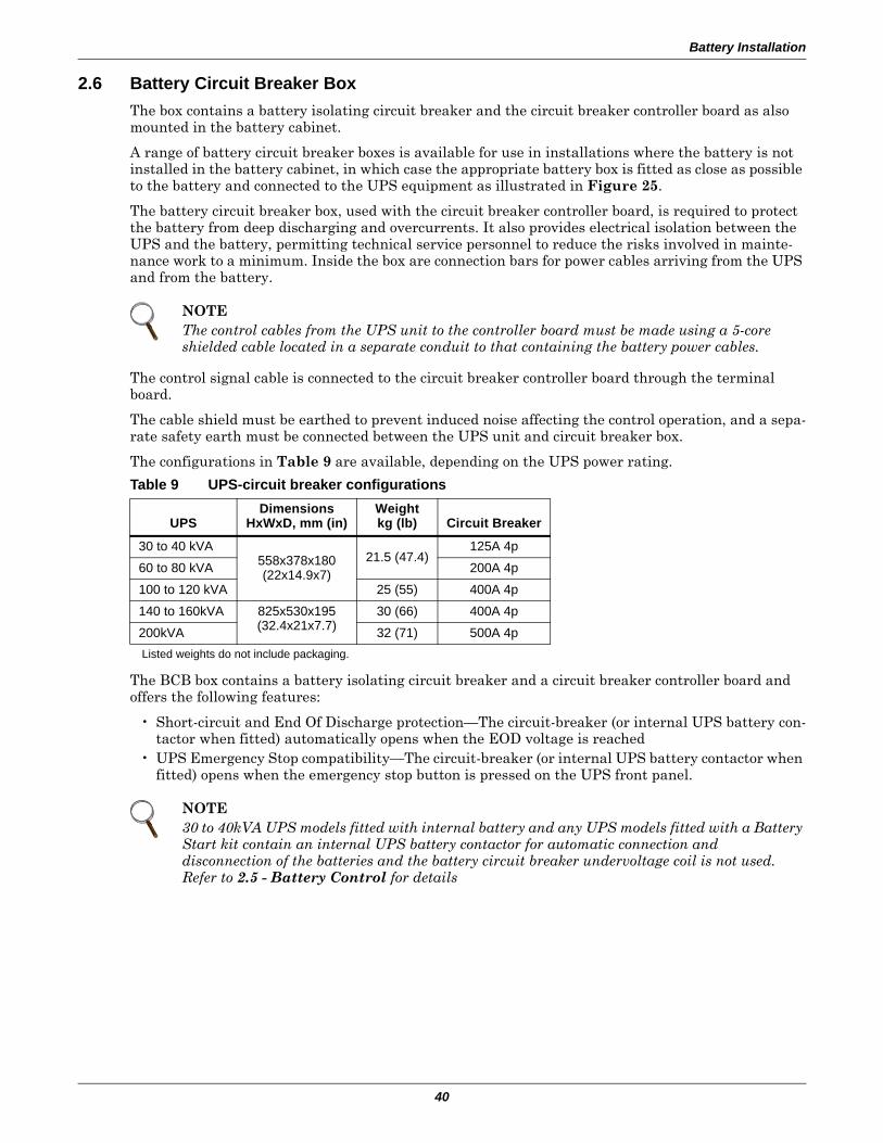
Battery Installation
40
2.6 Battery Circuit Breaker BoxThe box contains a battery isolating circuit breaker and the circuit breaker controller board as also mounted in the battery cabinet.
A range of battery circuit breaker boxes is available for use in installations where the battery is not installed in the battery cabinet, in which case the appropriate battery box is fitted as close as possible to the battery and connected to the UPS equipment as illustrated in Figure 25.
The battery circuit breaker box, used with the circuit breaker controller board, is required to protect the battery from deep discharging and overcurrents. It also provides electrical isolation between the UPS and the battery, permitting technical service personnel to reduce the risks involved in mainte-nance work to a minimum. Inside the box are connection bars for power cables arriving from the UPS and from the battery.
The control signal cable is connected to the circuit breaker controller board through the terminal board.
The cable shield must be earthed to prevent induced noise affecting the control operation, and a sepa-rate safety earth must be connected between the UPS unit and circuit breaker box.
The configurations in Table 9 are available, depending on the UPS power rating.
The BCB box contains a battery isolating circuit breaker and a circuit breaker controller board and offers the following features:
• Short-circuit and End Of Discharge protection—The circuit-breaker (or internal UPS battery con-tactor when fitted) automatically opens when the EOD voltage is reached
• UPS Emergency Stop compatibility—The circuit-breaker (or internal UPS battery contactor when fitted) opens when the emergency stop button is pressed on the UPS front panel.
NOTEThe control cables from the UPS unit to the controller board must be made using a 5-core shielded cable located in a separate conduit to that containing the battery power cables.
Table 9 UPS-circuit breaker configurations
UPSDimensions
HxWxD, mm (in)Weightkg (lb) Circuit Breaker
30 to 40 kVA558x378x180(22x14.9x7)
21.5 (47.4)125A 4p
60 to 80 kVA 200A 4p
100 to 120 kVA 25 (55) 400A 4p
140 to 160kVA 825x530x195(32.4x21x7.7)
30 (66) 400A 4p
200kVA 32 (71) 500A 4p Listed weights do not include packaging.
NOTE30 to 40kVA UPS models fitted with internal battery and any UPS models fitted with a Battery Start kit contain an internal UPS battery contactor for automatic connection and disconnection of the batteries and the battery circuit breaker undervoltage coil is not used. Refer to 2.5 - Battery Control for details
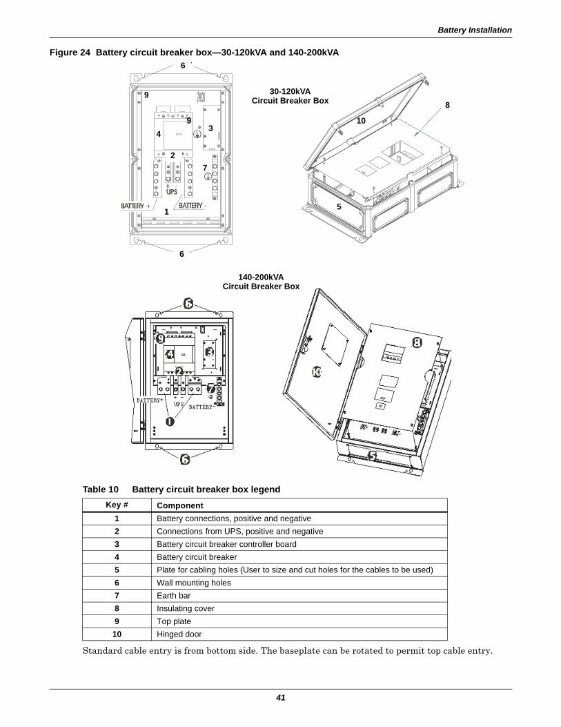
Battery Installation
41
Figure 24 Battery circuit breaker box—30-120kVA and 140-200kVA
Standard cable entry is from bottom side. The baseplate can be rotated to permit top cable entry.
Table 10 Battery circuit breaker box legendKey # Component
1 Battery connections, positive and negative2 Connections from UPS, positive and negative3 Battery circuit breaker controller board4 Battery circuit breaker5 Plate for cabling holes (User to size and cut holes for the cables to be used)6 Wall mounting holes7 Earth bar8 Insulating cover9 Top plate10 Hinged door
1
2
34
5
6
7
8
9
30-120kVACircuit Breaker Box
140-200kVACircuit Breaker Box
9
10
6
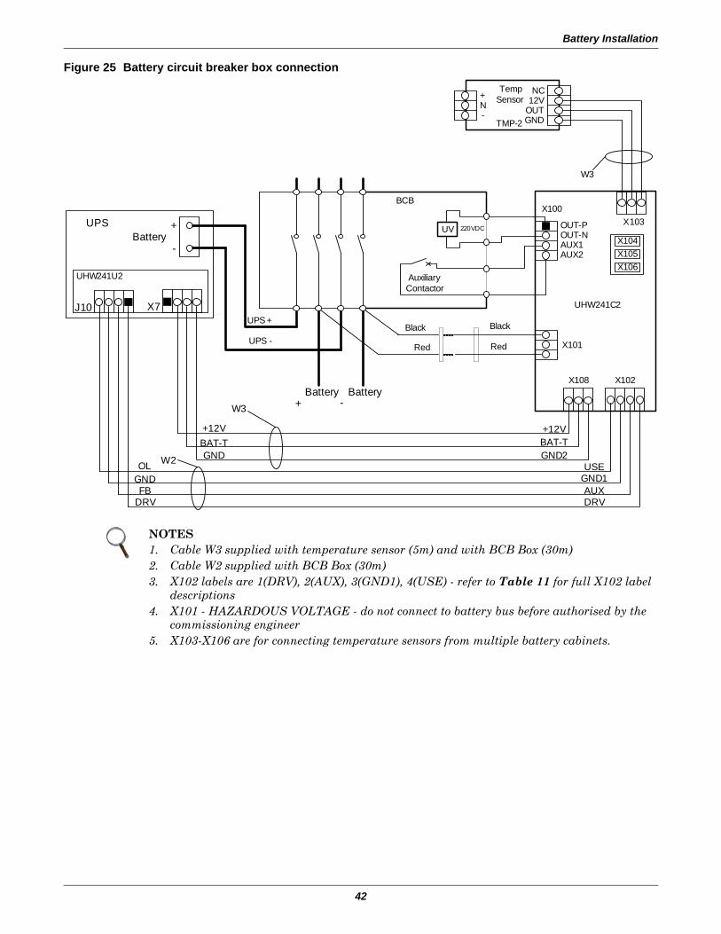
Battery Installation
42
Figure 25 Battery circuit breaker box connection
NOTES1. Cable W3 supplied with temperature sensor (5m) and with BCB Box (30m)2. Cable W2 supplied with BCB Box (30m)3. X102 labels are 1(DRV), 2(AUX), 3(GND1), 4(USE) - refer to Table 11 for full X102 label
descriptions4. X101 - HAZARDOUS VOLTAGE - do not connect to battery bus before authorised by the
commissioning engineer5. X103-X106 are for connecting temperature sensors from multiple battery cabinets.
Battery+
-
UPS
Battery+ -
Battery
X104X105X106
X103X100
X101
X108 X102
UHW241C2
Black
Red
OUT-POUT-NAUX1AUX2
Red
BlackUPS -
UPS +
Auxiliary Contactor
TempSensor+
N-
NC
OUTGND
12V
TMP-2
BCB
UV 220VDC
UHW241U2
J10 X7
+12VBAT-TGNDW2
W3
GNDOL
FBDRV
GND1USE
AUXDRV
+12VBAT-TGND2
W3
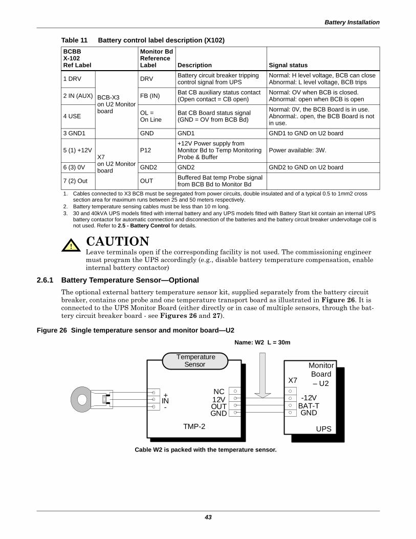
Battery Installation
43
2.6.1 Battery Temperature Sensor—OptionalThe optional external battery temperature sensor kit, supplied separately from the battery circuit breaker, contains one probe and one temperature transport board as illustrated in Figure 26. It is connected to the UPS Monitor Board (either directly or in case of multiple sensors, through the bat-tery circuit breaker board - see Figures 26 and 27).
Figure 26 Single temperature sensor and monitor board—U2
Table 11 Battery control label description (X102)BCBBX-102Ref Label
Monitor BdReferenceLabel Description Signal status
1 DRV
BCB-X3on U2 Monitorboard
DRV Battery circuit breaker tripping control signal from UPS
Normal: H level voltage, BCB can closeAbnormal: L level voltage, BCB trips
2 IN (AUX) FB (IN) Bat CB auxiliary status contact(Open contact = CB open)
Normal: OV when BCB is closed.Abnormal: open when BCB is open
4 USE OL = On Line
Bat CB Board status signal (GND = OV from BCB Bd)
Normal: 0V, the BCB Board is in use.Abnormal:. open, the BCB Board is not in use.
3 GND1 GND GND1 GND1 to GND on U2 board
5 (1) +12VX7on U2 Monitorboard
P12+12V Power supply from Monitor Bd to Temp Monitoring Probe & Buffer
Power available: 3W.
6 (3) 0V GND2 GND2 GND2 to GND on U2 board
7 (2) Out OUT Buffered Bat temp Probe signal from BCB Bd to Monitor Bd
1. Cables connected to X3 BCB must be segregated from power circuits, double insulated and of a typical 0.5 to 1mm2 cross section area for maximum runs between 25 and 50 meters respectively.
2. Battery temperature sensing cables must be less than 10 m long.3. 30 and 40kVA UPS models fitted with internal battery and any UPS models fitted with Battery Start kit contain an internal UPS
battery contactor for automatic connection and disconnection of the batteries and the battery circuit breaker undervoltage coil is not used. Refer to 2.5 - Battery Control for details.
! CAUTIONLeave terminals open if the corresponding facility is not used. The commissioning engineer must program the UPS accordingly (e.g., disable battery temperature compensation, enable internal battery contactor)
Temperature Sensor
TMP-2
+IN-
NC12V
GNDOUT
UPS
Monitor Board– U2X7
-12V
GNDBAT-T
Cable W2 is packed with the temperature sensor.
Name: W2 L = 30m
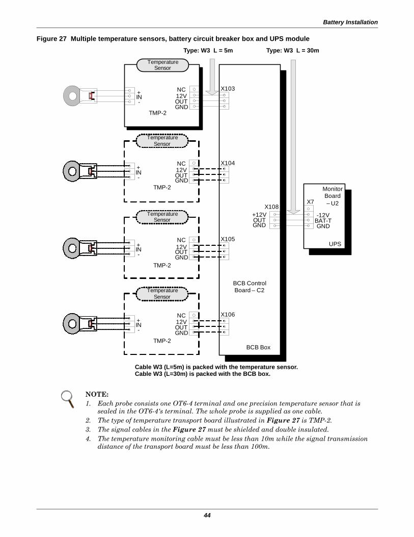
Battery Installation
44
Figure 27 Multiple temperature sensors, battery circuit breaker box and UPS module
NOTE:1. Each probe consists one OT6-4 terminal and one precision temperature sensor that is
sealed in the OT6-4's terminal. The whole probe is supplied as one cable. 2. The type of temperature transport board illustrated in Figure 27 is TMP-2.3. The signal cables in the Figure 27 must be shielded and double insulated.4. The temperature monitoring cable must be less than 10m while the signal transmission
distance of the transport board must be less than 100m.
Temperature Sensor
TMP-2
+IN-
NC12V
GNDOUT
BCB Box
BCB Control Board – C2
+12V
GNDOUT
X103
X105
X104
X106
X108
UPS
Monitor Board– U2X7
-12V
GNDBAT-T
Temperature Sensor
TMP-2
+IN-
NC12V
GNDOUT
Temperature Sensor
TMP-2
+IN-
NC12V
GNDOUT
Temperature Sensor
TMP-2
+IN-
NC12V
GNDOUT
Type: W3 L = 5m Type: W3 L = 30m
Cable W3 (L=5m) is packed with the temperature sensor.Cable W3 (L=30m) is packed with the BCB box.
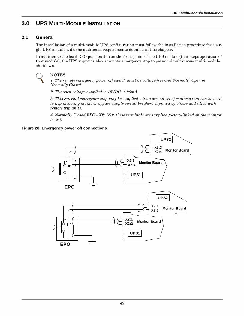
UPS Multi-Module Installation
45
3.0 UPS MULTI-MODULE INSTALLATION
3.1 GeneralThe installation of a multi-module UPS configuration must follow the installation procedure for a sin-gle UPS module with the additional requirements detailed in this chapter.
In addition to the local EPO push button on the front panel of the UPS module (that stops operation of that module), the UPS supports also a remote emergency stop to permit simultaneous multi-module shutdown.
Figure 28 Emergency power off connections
NOTES1. The remote emergency power off switch must be voltage-free and Normally Open or Normally Closed.
2. The open voltage supplied is 12VDC, < 20mA
3. This external emergency stop may be supplied with a second set of contacts that can be used to trip incoming mains or bypass supply circuit breakers supplied by others and fitted with remote trip units.
4. Normally Closed EPO - X2: 1&2, these terminals are supplied factory-linked on the monitor board.
UPS2
UPS1
Monitor Board
Monitor Board
X2:1X2:2
X2:1X2:2
EPO
UPS1
X2:3X2:4 Monitor Board
UPS2
X2:3X2:4 Monitor Board
EPO
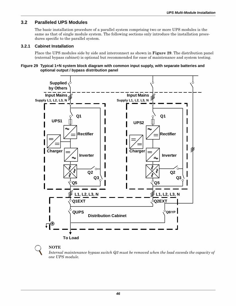
UPS Multi-Module Installation
46
3.2 Paralleled UPS Modules The basic installation procedure of a parallel system comprising two or more UPS modules is the same as that of single module system. The following sections only introduce the installation proce-dures specific to the parallel system.
3.2.1 Cabinet InstallationPlace the UPS modules side by side and interconnect as shown in Figure 29. The distribution panel (external bypass cabinet) is optional but recommended for ease of maintenance and system testing.
Figure 29 Typical 1+N system block diagram with common input supply, with separate batteries and optional output / bypass distribution panel
NOTEInternal maintenance bypass switch Q3 must be removed when the load exceeds the capacity of one UPS module.
To Load
Distribution Cabinet
Supplied by Others
Input MainsSupply L1, L2, L3, N
UPS1 UPS2Q1
Rectifier
InverterCharger
Q2Q3
Q5
Q2Q3
Q5
Rectifier
InverterCharger
Q1
Input MainsSupply L1, L2, L3, N
L1, L2, L3, NL1, L2, L3, N
QUPS QBYP
Q1EXT Q2EXT
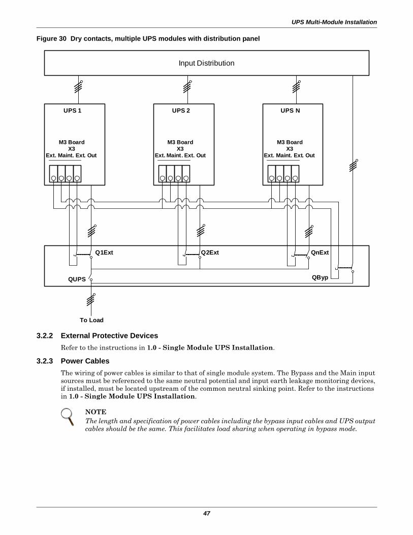
UPS Multi-Module Installation
47
Figure 30 Dry contacts, multiple UPS modules with distribution panel
3.2.2 External Protective DevicesRefer to the instructions in 1.0 - Single Module UPS Installation.
3.2.3 Power CablesThe wiring of power cables is similar to that of single module system. The Bypass and the Main input sources must be referenced to the same neutral potential and input earth leakage monitoring devices, if installed, must be located upstream of the common neutral sinking point. Refer to the instructions in 1.0 - Single Module UPS Installation.
NOTEThe length and specification of power cables including the bypass input cables and UPS output cables should be the same. This facilitates load sharing when operating in bypass mode.
Input Distribution
UPS 1
M3 BoardX3
Ext. Maint. Ext. Out
UPS 2
M3 BoardX3
Ext. Maint. Ext. Out
UPS N
M3 BoardX3
Ext. Maint. Ext. Out
To Load
QUPS QByp
Q1Ext Q2Ext QnExt
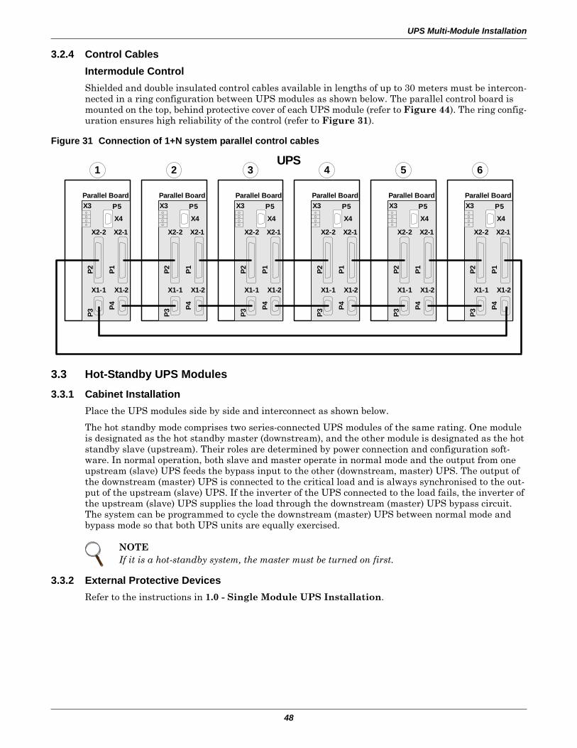
UPS Multi-Module Installation
48
3.2.4 Control CablesIntermodule ControlShielded and double insulated control cables available in lengths of up to 30 meters must be intercon-nected in a ring configuration between UPS modules as shown below. The parallel control board is mounted on the top, behind protective cover of each UPS module (refer to Figure 44). The ring config-uration ensures high reliability of the control (refer to Figure 31).
Figure 31 Connection of 1+N system parallel control cables
3.3 Hot-Standby UPS Modules
3.3.1 Cabinet InstallationPlace the UPS modules side by side and interconnect as shown below.
The hot standby mode comprises two series-connected UPS modules of the same rating. One module is designated as the hot standby master (downstream), and the other module is designated as the hot standby slave (upstream). Their roles are determined by power connection and configuration soft-ware. In normal operation, both slave and master operate in normal mode and the output from one upstream (slave) UPS feeds the bypass input to the other (downstream, master) UPS. The output of the downstream (master) UPS is connected to the critical load and is always synchronised to the out-put of the upstream (slave) UPS. If the inverter of the UPS connected to the load fails, the inverter of the upstream (slave) UPS supplies the load through the downstream (master) UPS bypass circuit. The system can be programmed to cycle the downstream (master) UPS between normal mode and bypass mode so that both UPS units are equally exercised.
3.3.2 External Protective DevicesRefer to the instructions in 1.0 - Single Module UPS Installation.
NOTEIf it is a hot-standby system, the master must be turned on first.
X1-1 X1-2
X2-2 X2-1
Parallel Board
X4
X3 P5
P3
P4P1P2
X1-1 X1-2
X2-2 X2-1
Parallel Board
X4
X3 P5
P3
P4P1P2
X1-1 X1-2
X2-2 X2-1
Parallel Board
X4
X3 P5
P3
P4P1P2
X1-1 X1-2
X2-2 X2-1
Parallel Board
X4
X3 P5
P3
P4P1P2
X1-1 X1-2
X2-2 X2-1
Parallel Board
X4
X3 P5
P3
P4P1P2
X1-1 X1-2
X2-2 X2-1
Parallel Board
X4
X3 P5
P3
P4P1P2
1 2 3 4 5 6UPS
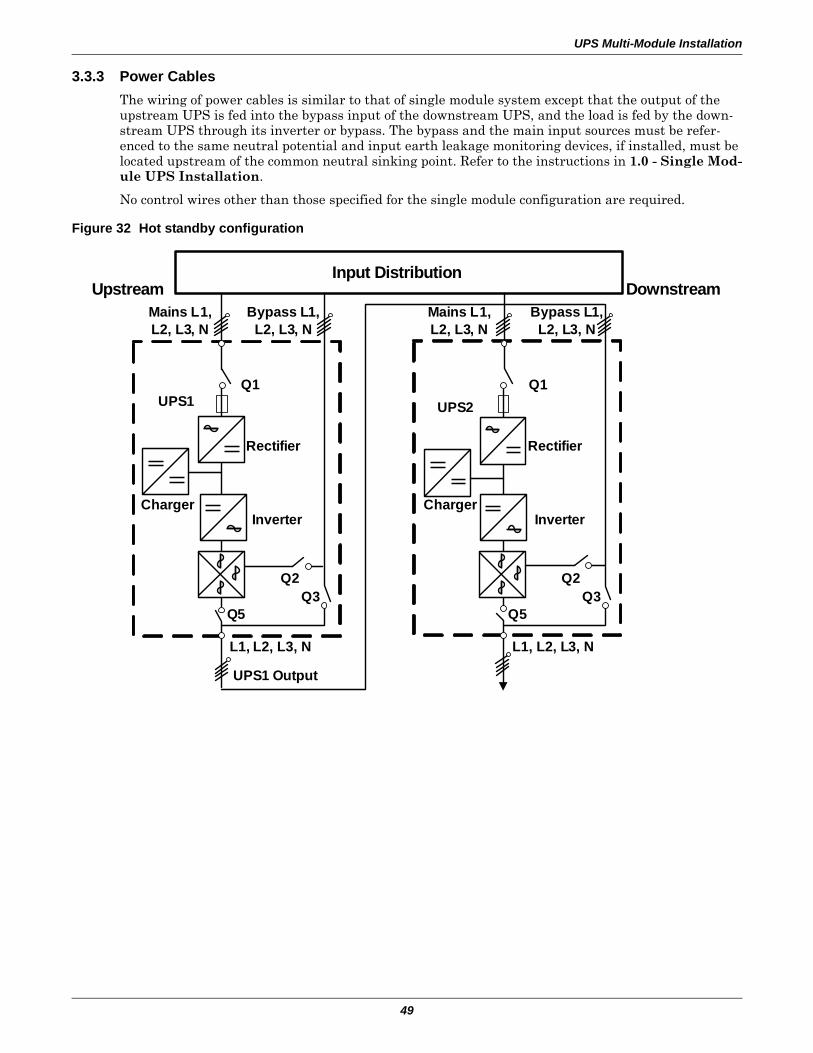
UPS Multi-Module Installation
49
3.3.3 Power CablesThe wiring of power cables is similar to that of single module system except that the output of the upstream UPS is fed into the bypass input of the downstream UPS, and the load is fed by the down-stream UPS through its inverter or bypass. The bypass and the main input sources must be refer-enced to the same neutral potential and input earth leakage monitoring devices, if installed, must be located upstream of the common neutral sinking point. Refer to the instructions in 1.0 - Single Mod-ule UPS Installation.
No control wires other than those specified for the single module configuration are required.
Figure 32 Hot standby configuration
Mains L1, L2, L3, N
UPS1 UPS2Q1
Rectifier
InverterCharger
Q2Q3
Q5
Q2Q3
Q5
Rectifier
InverterCharger
Q1
L1, L2, L3, NL1, L2, L3, N
Mains L1, L2, L3, N
Input Distribution
Bypass L1, L2, L3, N
Bypass L1, L2, L3, N
UPS1 Output
Upstream Downstream
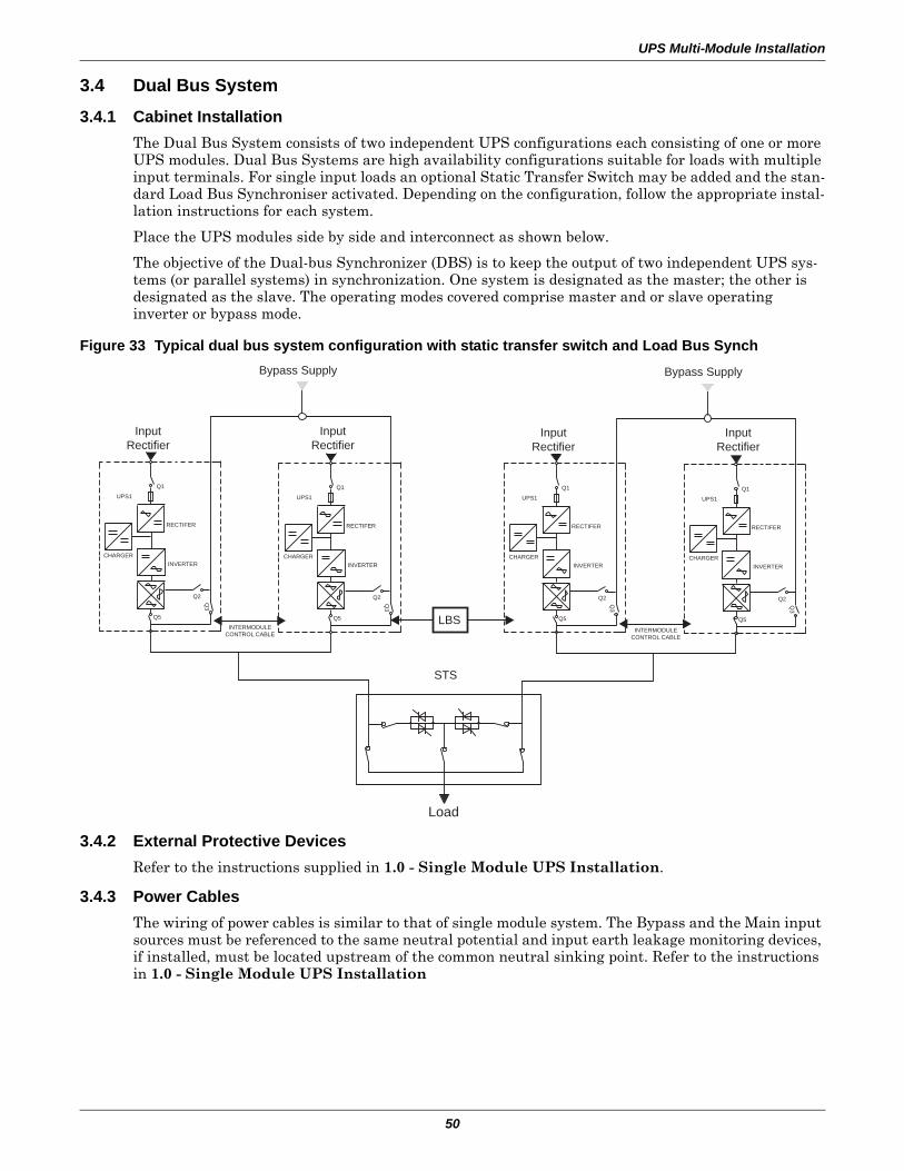
UPS Multi-Module Installation
50
3.4 Dual Bus System
3.4.1 Cabinet InstallationThe Dual Bus System consists of two independent UPS configurations each consisting of one or more UPS modules. Dual Bus Systems are high availability configurations suitable for loads with multiple input terminals. For single input loads an optional Static Transfer Switch may be added and the stan-dard Load Bus Synchroniser activated. Depending on the configuration, follow the appropriate instal-lation instructions for each system.
Place the UPS modules side by side and interconnect as shown below.
The objective of the Dual-bus Synchronizer (DBS) is to keep the output of two independent UPS sys-tems (or parallel systems) in synchronization. One system is designated as the master; the other is designated as the slave. The operating modes covered comprise master and or slave operating inverter or bypass mode.
Figure 33 Typical dual bus system configuration with static transfer switch and Load Bus Synch
3.4.2 External Protective DevicesRefer to the instructions supplied in 1.0 - Single Module UPS Installation.
3.4.3 Power CablesThe wiring of power cables is similar to that of single module system. The Bypass and the Main input sources must be referenced to the same neutral potential and input earth leakage monitoring devices, if installed, must be located upstream of the common neutral sinking point. Refer to the instructions in 1.0 - Single Module UPS Installation
STS
Load
UPS1
Q1
CHARGER
RECTIFER
INVERTER
Q5
Q3
Q2
UPS1
Q1
CHARGER
RECTIFER
INVERTER
Q5
Q3
Q2
LBS
InputRectifier
InputRectifier
Bypass Supply
UPS1
Q1
CHARGER
RECTIFER
INVERTER
INTERMODULECONTROL CABLE
Q5
Q3
Q2
UPS1
Q1
CHARGER
RECTIFER
INVERTER
Q5
Q3
Q2
InputRectifier
InputRectifier
Bypass Supply
INTERMODULECONTROL CABLE
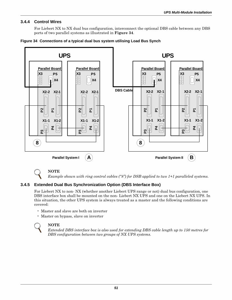
UPS Multi-Module Installation
51
3.4.4 Control WiresFor Liebert NX to NX dual bus configuration, interconnect the optional DBS cable between any DBS ports of two parallel systems as illustrated in Figure 34.
Figure 34 Connections of a typical dual bus system utilising Load Bus Synch
3.4.5 Extended Dual Bus Synchronization Option (DBS Interface Box)For Liebert NX to non- NX (whether another Liebert UPS range or not) dual bus configuration, one DBS interface box shall be mounted on the non- Liebert NX UPS and one on the Liebert NX UPS. In this situation, the other UPS system is always treated as a master and the following conditions are covered:
• Master and slave are both on inverter• Master on bypass, slave on inverter
NOTEExample shown with ring control cables (“8”) for DSB applied to two 1+1 paralleled systems.
NOTEExtended DBS interface box is also used for extending DBS cable length up to 150 metres for DBS configuration between two groups of NX UPS systems.
UPS
X1-1 X1-2
X2-2 X2-1
Parallel Board
X4
X3 P5
P3
P4P1P2
X1-1 X1-2
X2-2 X2-1
Parallel Board
X4
X3 P5
P3
P4P1P2
8
X1-1 X1-2
X2-2 X2-1
Parallel Board
X4
X3 P5
P3
P4P
1
P2
X1-1 X1-2
X2-2 X2-1
Parallel Board
X4
X3 P5P3
P4P
1
P2
8
UPS
BParallel System I Parallel System II
DBS Cable
A
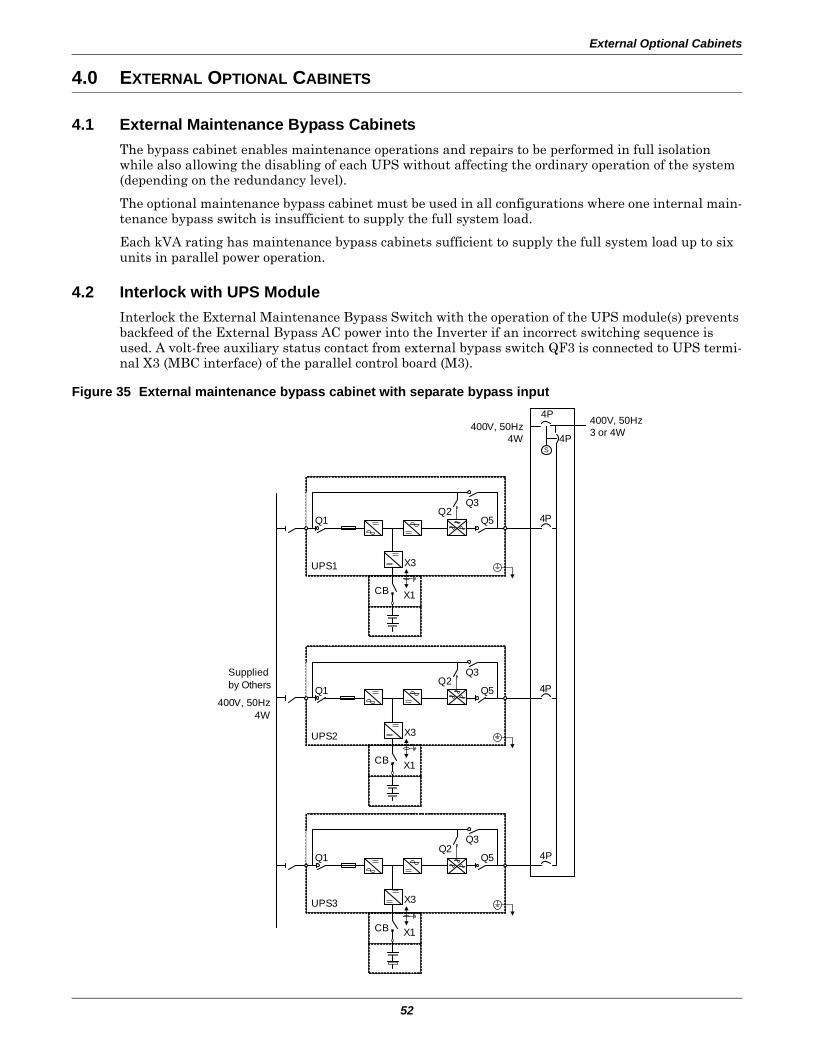
External Optional Cabinets
52
4.0 EXTERNAL OPTIONAL CABINETS
4.1 External Maintenance Bypass CabinetsThe bypass cabinet enables maintenance operations and repairs to be performed in full isolation while also allowing the disabling of each UPS without affecting the ordinary operation of the system (depending on the redundancy level).
The optional maintenance bypass cabinet must be used in all configurations where one internal main-tenance bypass switch is insufficient to supply the full system load.
Each kVA rating has maintenance bypass cabinets sufficient to supply the full system load up to six units in parallel power operation.
4.2 Interlock with UPS ModuleInterlock the External Maintenance Bypass Switch with the operation of the UPS module(s) prevents backfeed of the External Bypass AC power into the Inverter if an incorrect switching sequence is used. A volt-free auxiliary status contact from external bypass switch QF3 is connected to UPS termi-nal X3 (MBC interface) of the parallel control board (M3).
Figure 35 External maintenance bypass cabinet with separate bypass input4P
4P400V, 50Hz
4WS
Q1Q2
Q3
Q5
X3
X1CB
4P
Q1Q2
Q3
Q5
X3
X1CB
4P
UPS2
UPS3
400V, 50Hz3 or 4W
400V, 50Hz4W
Suppliedby Others
Q1Q2
Q3
Q5
X3
X1CB
4P
UPS1
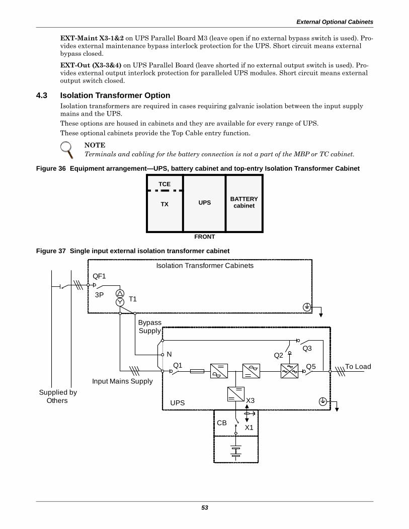
External Optional Cabinets
53
EXT-Maint X3-1&2 on UPS Parallel Board M3 (leave open if no external bypass switch is used). Pro-vides external maintenance bypass interlock protection for the UPS. Short circuit means external bypass closed.
EXT-Out (X3-3&4) on UPS Parallel Board (leave shorted if no external output switch is used). Pro-vides external output interlock protection for paralleled UPS modules. Short circuit means external output switch closed.
4.3 Isolation Transformer OptionIsolation transformers are required in cases requiring galvanic isolation between the input supply mains and the UPS.These options are housed in cabinets and they are available for every range of UPS.These optional cabinets provide the Top Cable entry function.
Figure 36 Equipment arrangement—UPS, battery cabinet and top-entry Isolation Transformer Cabinet
Figure 37 Single input external isolation transformer cabinet
NOTETerminals and cabling for the battery connection is not a part of the MBP or TC cabinet.
TCE
TX UPS BATTERYcabinet
FRONT
Q1
Q3
Q5
X3
X1CB
To Load
UPS
N
Bypass Supply
Input Mains Supply
3P
Supplied by Others
Isolation Transformer Cabinets
T1
QF1
Q2
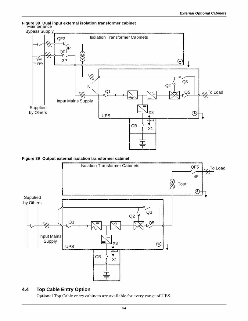
External Optional Cabinets
54
Figure 38 Dual input external isolation transformer cabinet
Figure 39 Output external isolation transformer cabinet
4.4 Top Cable Entry OptionOptional Top Cable entry cabinets are available for every range of UPS.
Q1
Q3
Q5
X3
X1CB
To Load
UPS
Input Mains Supply
3P
Suppliedby Others
Isolation Transformer CabinetsQF2
Q2
3PQF1
Maintenance Bypass Supply
InputSupply
N
Q1
Q3
Q5
X3
X1CB
To Load
UPS
Input Mains Supply
Supplied by Others
Isolation Transformer Cabinets
Q2
Tout
QF5
4P
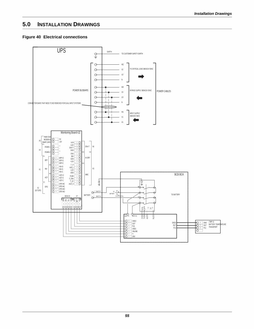
Installation Drawings
55
5.0 INSTALLATION DRAWINGS
Figure 40 Electrical connections
N.O
.
V< NP
2
2
43
23
43
4
BFP-OBFP-SBFP-C
INV-CINV-SINV-O
ACF-CACF-SACF-O
+-+-
0V
GND
1
432
A-IN+12V
ENV-TGNDENV
+12VGENBtG
1
432
GND+12V
T_ITAUX_I
43
12
FUSE 1
T_OTAUX_O
F_FAN34
2
EPO-NO
1
3 EPO-NO2 EPO-NC1 EPO-NC
BFP
INV
ACF
EPO
RS485-2
RS485-1 ENV-T
IN DRY
MBC
PWR FOR MODEM &
SNMP CARD
X6
X3X1
X4
X5
X2EXT EPO
Monitoring Board-U2
BAT-T
+12VGN
D
DRV
FB OL
2 4 3 432
BCB-X3 X7
4
-
+
123
DRV
ONLINEIN
P12GND1
OUT754
6 GND2
AUX-2AUX-1OUT-P
OUT-N
OUTP12
GND32
4 (TMP-2)BATTERY TEMPERATURE TRANSPORT
GND2OUTP12
BAT-P BAT-N
BATTERY
BAT-P
BAT-N
BCB BOX
UPS
TO BATTERY
EARTHTO CUSTOMER SAFETY EARTH
W2
V2
U2
N
N
U3
V3
W3
U1
V1
W1 INPUT SUPPLY380/415V 50HZ
BYPASS SUPPLY 380/415V 50HZ
TO CRITICAL LOAD 380/415V 50HZ
POWER CABLESPOWER BUSBARS
CONNECTOR BARS THAT NEED TO BE REMOVED FOR DUAL INPUT SYSTEMS
12V
PTOBATTERY N
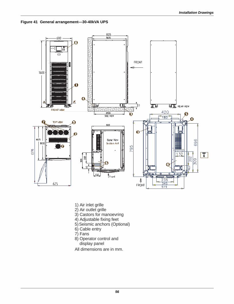
Installation Drawings
56
Figure 41 General arrangement—30-40kVA UPS
1) Air inlet grille 2) Air outlet grille 3) Castors for manoevring 4) Adjustable fixing feet 5) Seismic anchors (Optional) 6) Cable entry 7) Fans 8) Operator control and
display panel All dimensions are in mm.
825
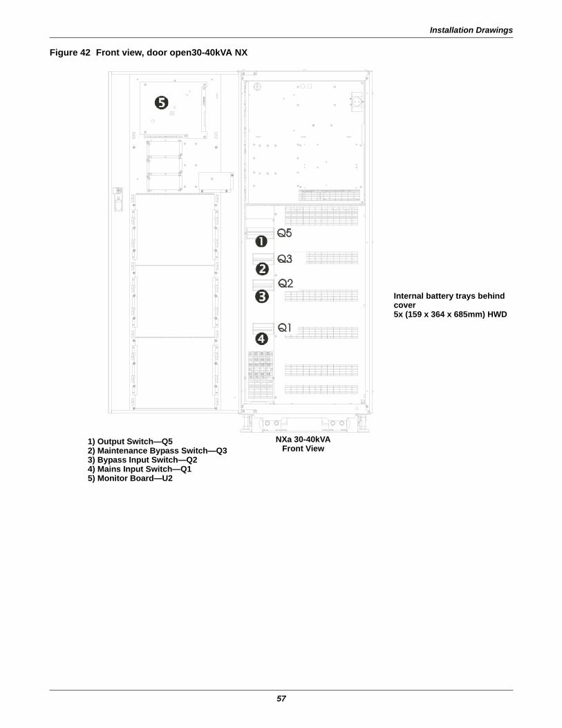
Installation Drawings
57
Figure 42 Front view, door open30-40kVA NX
Internal battery trays behind cover5x (159 x 364 x 685mm) HWD
NXa 30-40kVAFront View
1) Output Switch—Q52) Maintenance Bypass Switch—Q33) Bypass Input Switch—Q24) Mains Input Switch—Q15) Monitor Board—U2
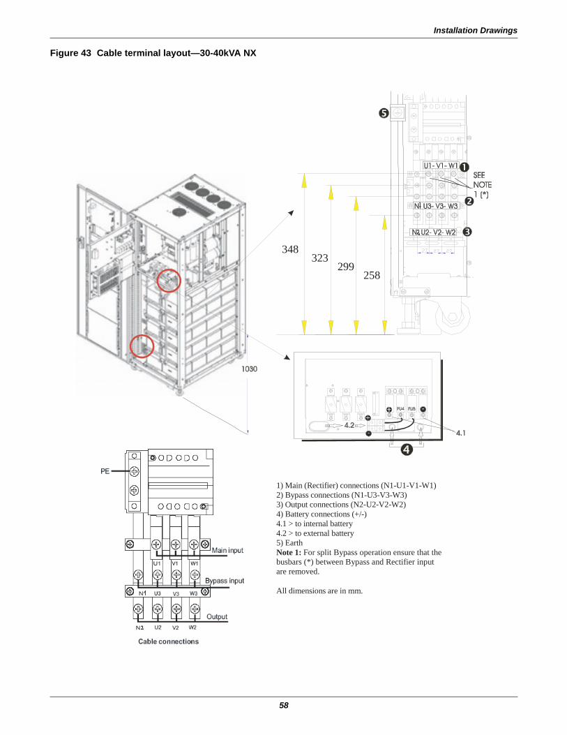
Installation Drawings
58
Figure 43 Cable terminal layout—30-40kVA NX
1) Main (Rectifier) connections (N1-U1-V1-W1) 2) Bypass connections (N1-U3-V3-W3) 3) Output connections (N2-U2-V2-W2) 4) Battery connections (+/-) 4.1 > to internal battery 4.2 > to external battery 5) Earth Note 1: For split Bypass operation ensure that the busbars (*) between Bypass and Rectifier input are removed. All dimensions are in mm.
348323
299258
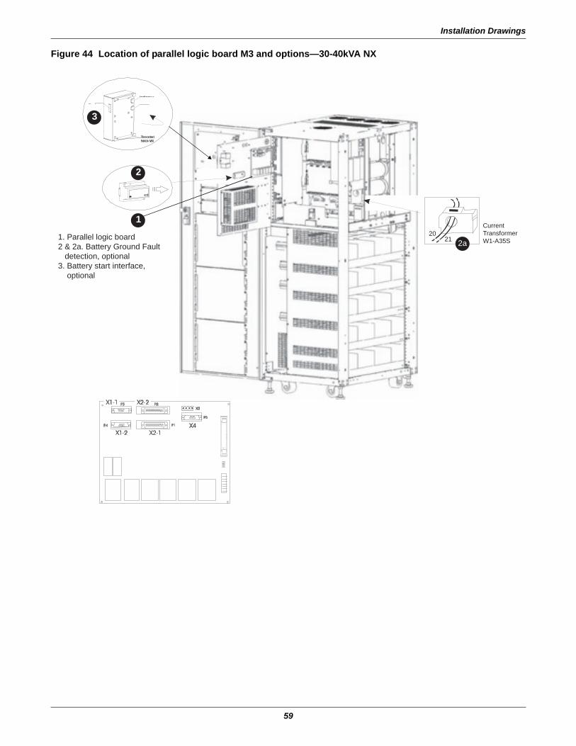
Installation Drawings
59
Figure 44 Location of parallel logic board M3 and options—30-40kVA NX
S k t
Indicator
B tt
1. Parallel logic board2 & 2a. Battery Ground Fault detection, optional3. Battery start interface, optional
CurrentTransformerW1-A35S
2021 2a
3
1
2
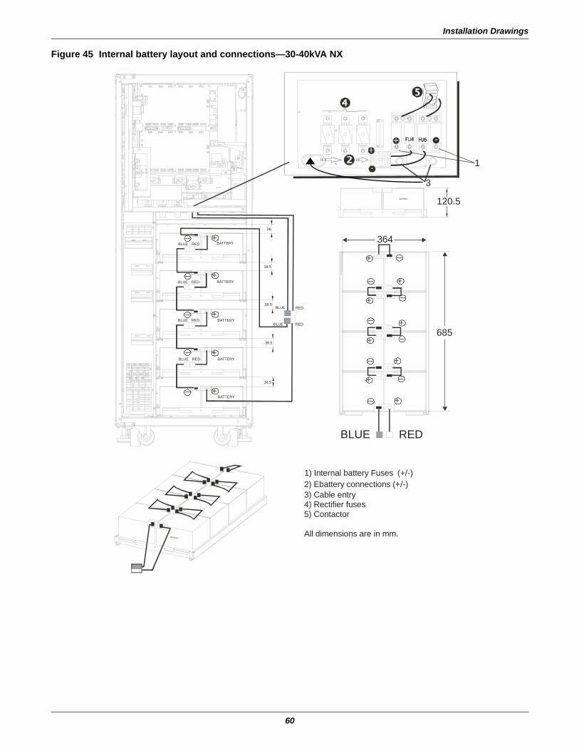
Installation Drawings
60
Figure 45 Internal battery layout and connections—30-40kVA NX
+
+
+
+
+
+
+
+
+
+
+
+
+
1) Internal battery Fuses (+/-)
2) Ebattery connections (+/-) 3) Cable entry 4) Rectifier fuses 5) Contactor
All dimensions are in mm.
120.5
364
1
3BATTERY
RED
RED
RED
BLUE
BLUE
REDBLUE
REDBLUE
REDBLUE
38.5
38.5
38.5
38.5
36
BATTERY
BATTERY
BATTERY
BATTERY
BATTERY
BATTERY
BLUE RED
BLUE
685
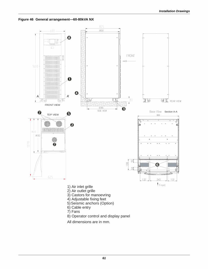
Installation Drawings
61
Figure 46 General arrangement—60-80kVA NX
1) Air inlet grille 2) Air outlet grille 3) Castors for manoevring 4) Adjustable fixing feet 5) Seismic anchors (Option) 6) Cable entry 7) Fans8) Operator control and display panel
All dimensions are in mm.
FRONT VIEW
Section A-ATOP VIEW

Installation Drawings
62
Figure 47 Front view doors open—60-80kVA NX
1) Parallel logic board 2) Monitor board 3) Battery start Interface 4 and 4a) Battery Ground Fault detection (optional)
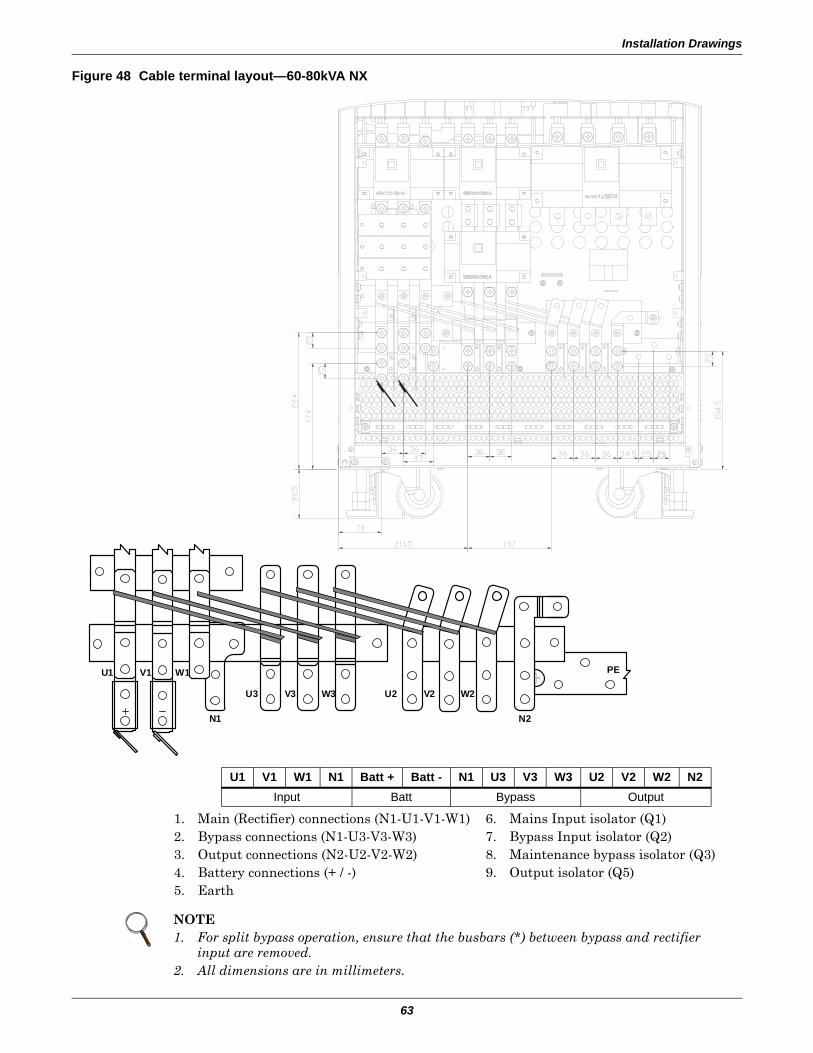
Installation Drawings
63
Figure 48 Cable terminal layout—60-80kVA NX
1. Main (Rectifier) connections (N1-U1-V1-W1)2. Bypass connections (N1-U3-V3-W3)3. Output connections (N2-U2-V2-W2)4. Battery connections (+ / -)5. Earth
6. Mains Input isolator (Q1)7. Bypass Input isolator (Q2)8. Maintenance bypass isolator (Q3)9. Output isolator (Q5)
U1 V1 W1 N1 Batt + Batt - N1 U3 V3 W3 U2 V2 W2 N2Input Batt Bypass Output
NOTE1. For split bypass operation, ensure that the busbars (*) between bypass and rectifier
input are removed.2. All dimensions are in millimeters.
U1 V1 W1
U3 V3 W3
N1 N2
U2 V2 W2
PE
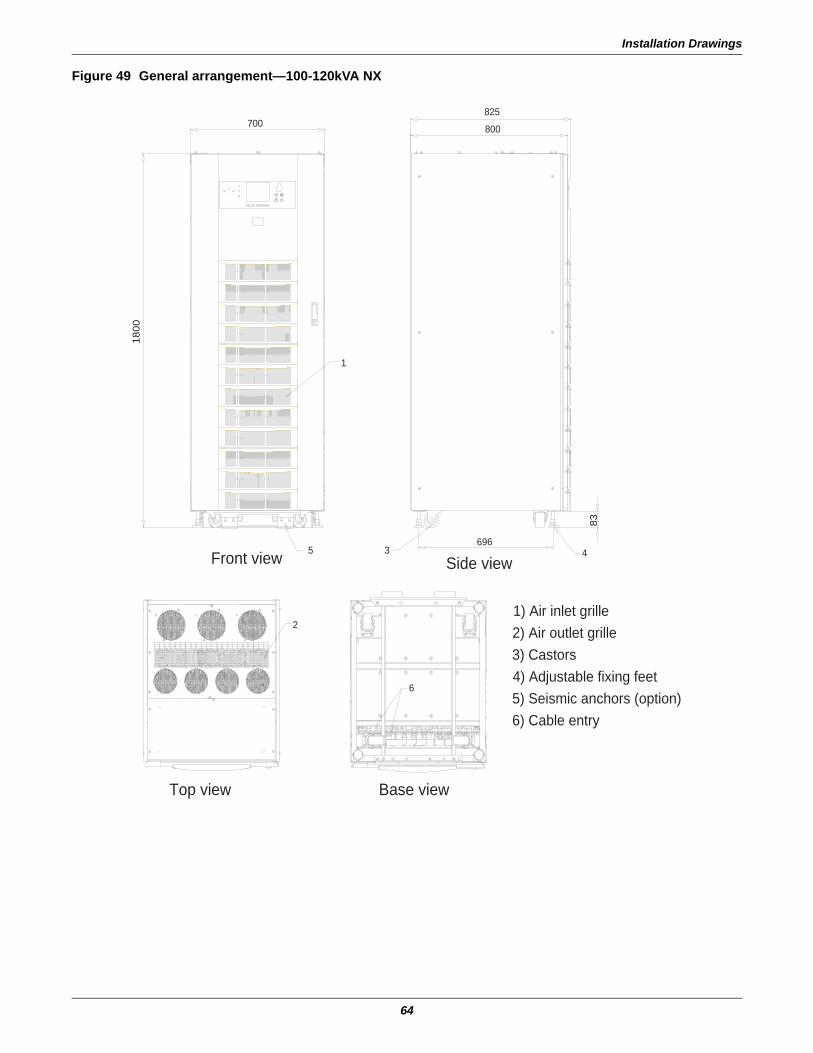
Installation Drawings
64
Figure 49 General arrangement—100-120kVA NX
Front view Side view
1) Air inlet grille2) Air outlet grille3) Castors4) Adjustable fixing feet5) Seismic anchors (option)6) Cable entry
Base viewTop view
70018
00
1
5 3696
83
4
800
825
2
6
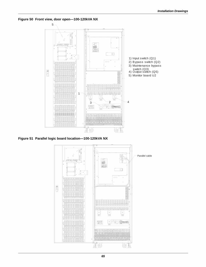
Installation Drawings
65
Figure 50 Front view, door open—100-120kVA NX
Figure 51 Parallel logic board location—100-120kVA NX
1) Input switch (Q1)2) Bypass switch (Q2)3) Maintenance bypass switch (Q3)4) Output switch (Q5)5) Monitor board U2
5
1
23 4
Parallel cable
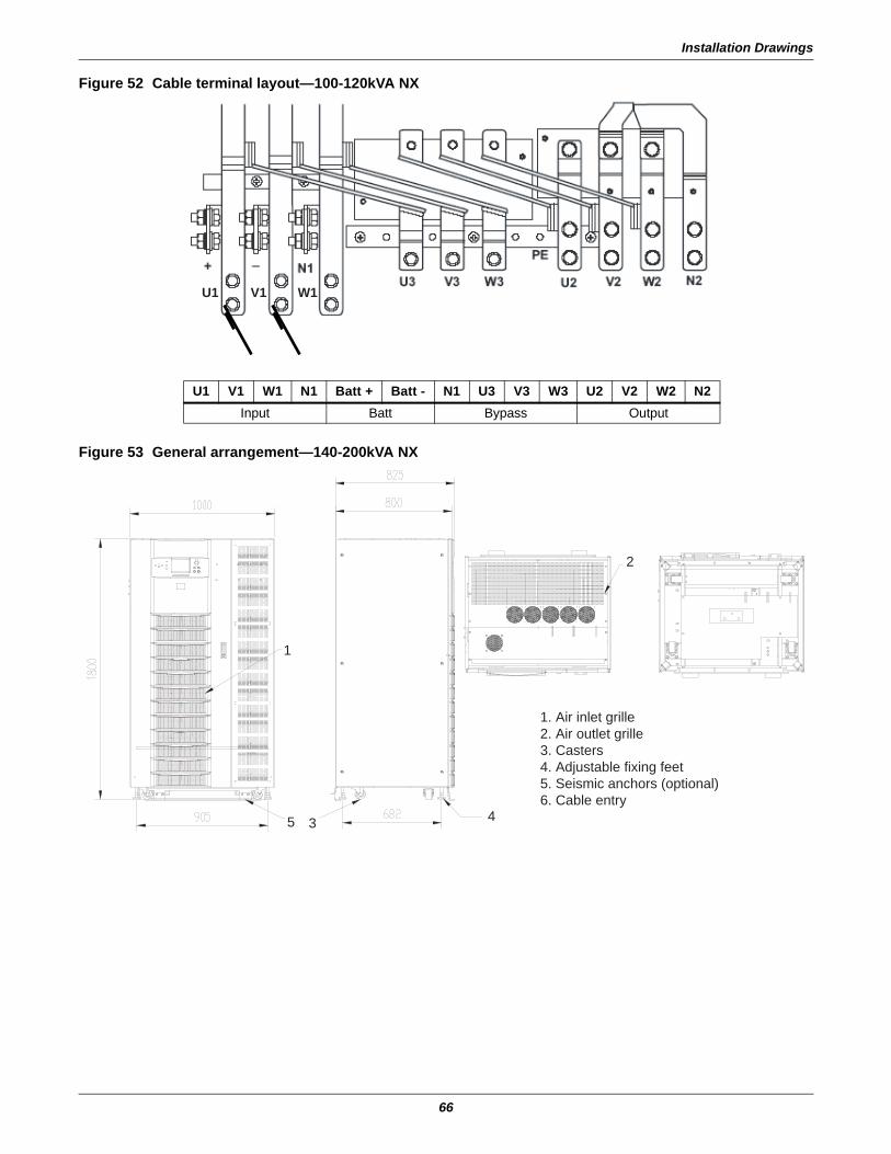
Installation Drawings
66
Figure 52 Cable terminal layout—100-120kVA NX
Figure 53 General arrangement—140-200kVA NX
U1 V1 W1
U1 V1 W1 N1 Batt + Batt - N1 U3 V3 W3 U2 V2 W2 N2Input Batt Bypass Output
1. Air inlet grille2. Air outlet grille3. Casters4. Adjustable fixing feet5. Seismic anchors (optional)6. Cable entry
1
2
45 3
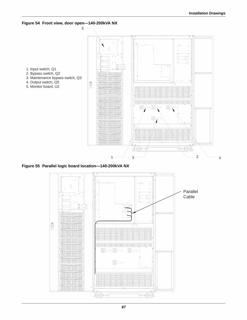
Installation Drawings
67
Figure 54 Front view, door open—140-200kVA NX
Figure 55 Parallel logic board location—140-200kVA NX
5
1
1. Input switch, Q12. Bypass switch, Q23. Maintenance bypass switch, Q34. Output switch, Q55. Monitor board, U2
3 2 4
ParallelCable
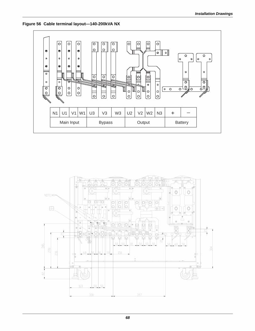
Installation Drawings
68
Figure 56 Cable terminal layout—140-200kVA NX
U3 V3 W3 U2 V2 W2 N3N1 W1V1U1
BypassMain Input Output Battery
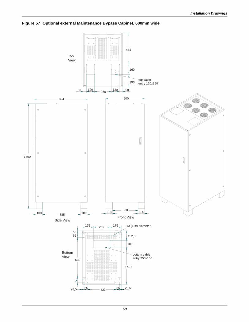
Installation Drawings
69
Figure 57 Optional external Maintenance Bypass Cabinet, 600mm wide
top cableentry 120x160
bottom cableentry 250x100
28,5 55 433 55 28,5
5055
630
55
175250175
152,5
100
571,5
13 (12x) diameter
100585100 100388100
1600
824 600
50 120260
120 50
190
160
474
BottomView
Side View
TopView
Front View
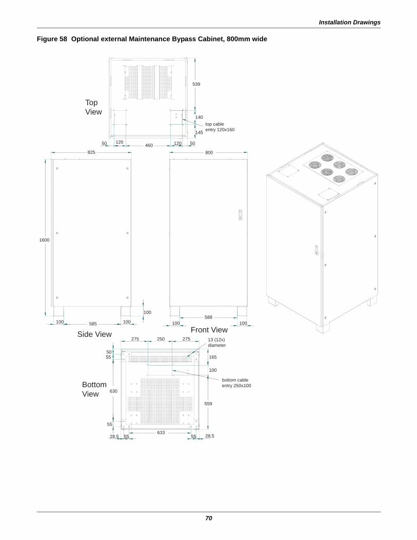
Installation Drawings
70
Figure 58 Optional external Maintenance Bypass Cabinet, 800mm wide
top cableentry 120x160
bottom cableentry 250x100
28,555633
5528,5
5055
630
55
250275 275
800825
1600
100 585 100 100588
100
165
100
559
100
50 120460 120 50
145
140
539
13 (12x)diameter
BottomView
Side View Front View
TopView
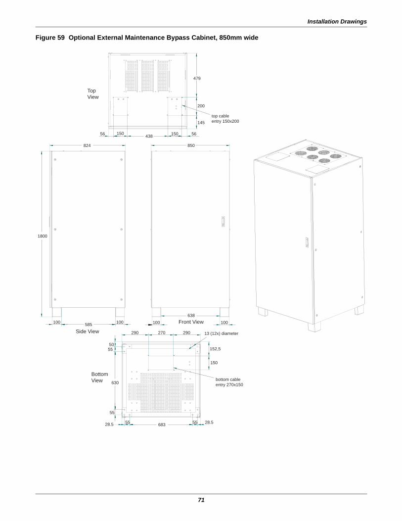
Installation Drawings
71
Figure 59 Optional External Maintenance Bypass Cabinet, 850mm wide
top cableentry 150x200
bottom cableentry 270x150
824
1800
100 585 100 100638
100
850
28.5 55 683 55 28.5
5055
55
630
290 270 290
150
152,5
13 (12x) diameter
56 150 438 150 56
145
200
479
BottomView
Side View
TopView
Front View
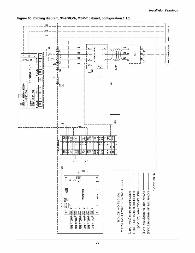
Installation Drawings
72
Figure 60 Cabling diagram, 30-200kVA, MBP-T cabinet, configuration 1.1.1
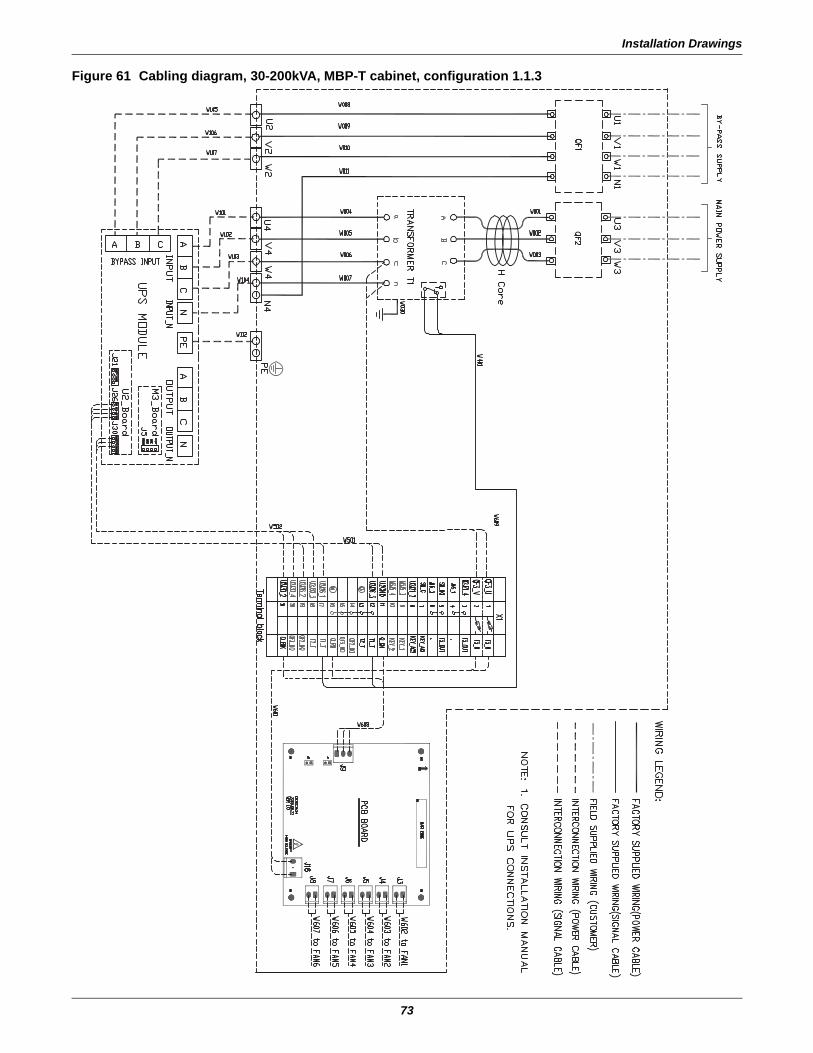
Installation Drawings
73
Figure 61 Cabling diagram, 30-200kVA, MBP-T cabinet, configuration 1.1.3
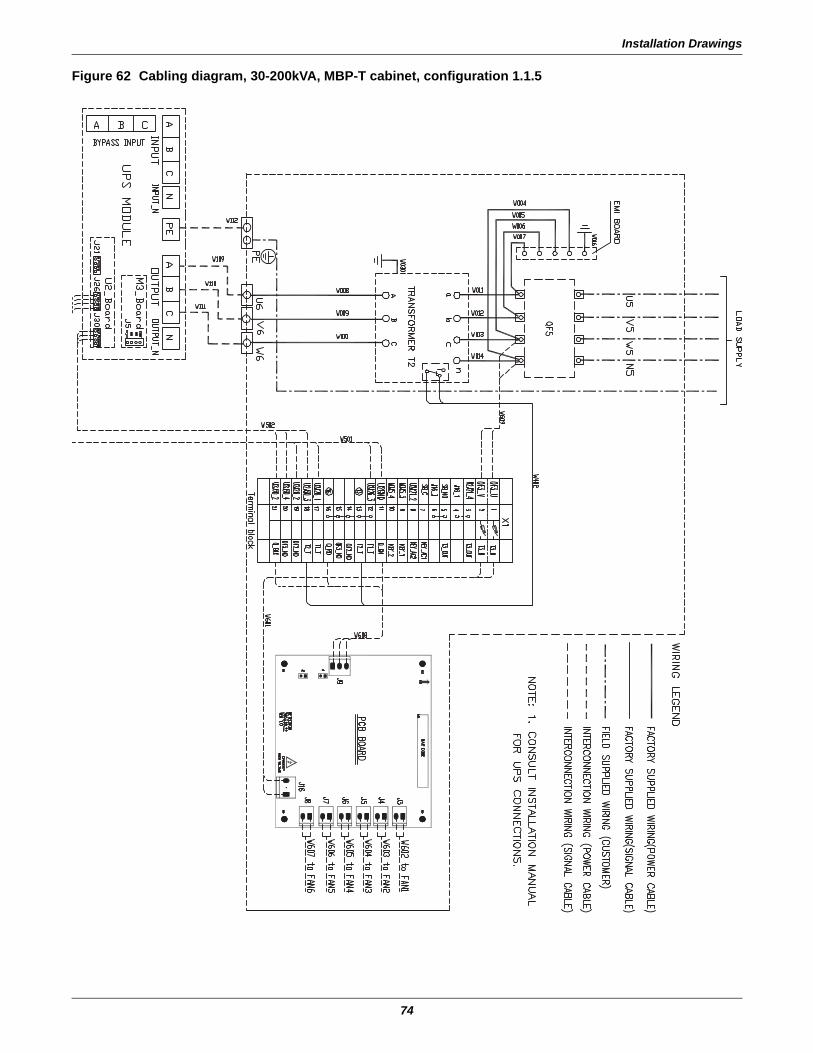
Installation Drawings
74
Figure 62 Cabling diagram, 30-200kVA, MBP-T cabinet, configuration 1.1.5
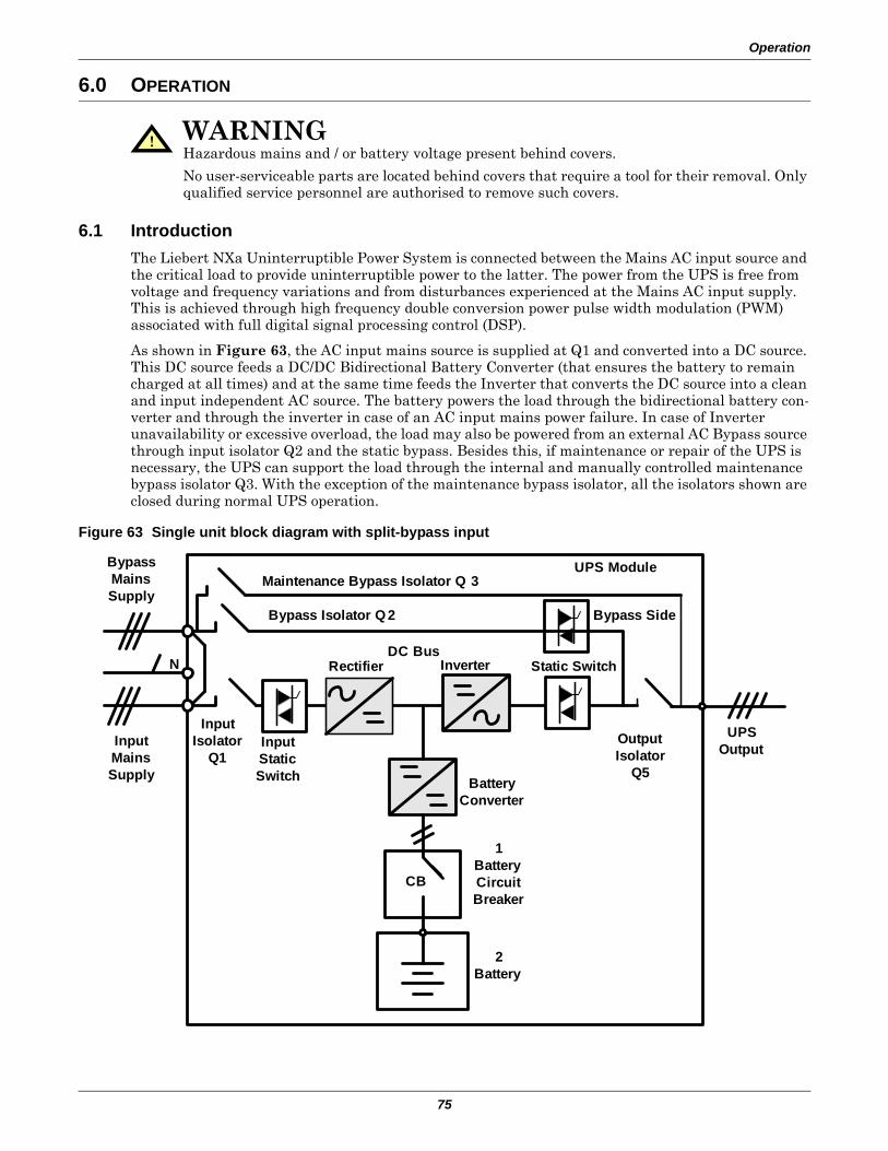
Operation
75
6.0 OPERATION
6.1 IntroductionThe Liebert NXa Uninterruptible Power System is connected between the Mains AC input source and the critical load to provide uninterruptible power to the latter. The power from the UPS is free from voltage and frequency variations and from disturbances experienced at the Mains AC input supply. This is achieved through high frequency double conversion power pulse width modulation (PWM) associated with full digital signal processing control (DSP).
As shown in Figure 63, the AC input mains source is supplied at Q1 and converted into a DC source. This DC source feeds a DC/DC Bidirectional Battery Converter (that ensures the battery to remain charged at all times) and at the same time feeds the Inverter that converts the DC source into a clean and input independent AC source. The battery powers the load through the bidirectional battery con-verter and through the inverter in case of an AC input mains power failure. In case of Inverter unavailability or excessive overload, the load may also be powered from an external AC Bypass source through input isolator Q2 and the static bypass. Besides this, if maintenance or repair of the UPS is necessary, the UPS can support the load through the internal and manually controlled maintenance bypass isolator Q3. With the exception of the maintenance bypass isolator, all the isolators shown are closed during normal UPS operation.
Figure 63 Single unit block diagram with split-bypass input
! WARNINGHazardous mains and / or battery voltage present behind covers.
No user-serviceable parts are located behind covers that require a tool for their removal. Only qualified service personnel are authorised to remove such covers.
1Battery Circuit Breaker
2Battery
UPS Output
Battery Converter
Input Static Switch
Input Isolator
Q1
Rectifier Inverter Static Switch
Output Isolator
Q5
DC Bus
Bypass Isolator Q 2
Maintenance Bypass Isolator Q 3UPS ModuleBypass
Mains Supply
Input Mains Supply
N
Bypass Side
CB
Operation
76
6.1.1 Split-Bypass InputFigure 63 illustrates the Liebert NX UPS in what is known as the split-bypass configuration wherein a separate power switch to a dedicated bypass power source that also feeds the maintenance bypass line connects the static bypass line. Where a separate power source is not available, the bypass and rectifier input supply connections are linked.
6.1.2 Static Transfer SwitchThe circuit blocks labeled Static Switch in Figure 63 contain electronically controlled switching cir-cuits that enable the critical load to be connected to either the inverter output or to a bypass power source via the static bypass line. During normal system operation the load is connected to the inverter; but in the event of a UPS overload or inverter failure, the load is automatically transferred to the static bypass line.
To provide a clean (no-break) load transfer between the inverter output and static bypass line, the static switch activates, connecting the load to bypass. To achieve this, the inverter output and bypass supply must be fully synchronized during normal operating conditions. This is achieved through the inverter control electronics, which make the inverter frequency track that of the static bypass supply, provided that the bypass remains within an acceptable frequency window.
A manually controlled, maintenance bypass supply is incorporated into the UPS design. It enables the critical load to be powered from the utility (bypass) supply while the UPS is shut down for routine maintenance.
6.1.3 Battery Circuit BreakerAny external battery is connected to UPS through a circuit breaker fitted inside the battery cabinet –or located adjacent to the batteries where a battery cabinet is not used. This circuit breaker is closed manually, but it contains an undervoltage release coil, which enables it to be tripped from the UPS control electronics following certain detected faults. It also has a magnetic trip facility for overload protection. The undervoltage release coil control is replaced by a battery contactor located inside the UPS fitted with either internal batteries or with battery start option or both
6.1.4 Battery Temperature CompensationFor 30-40kVA UPS with internal batteries, a standard temperature probe is installed to measure the internal battery temperature to optimize battery management. The measured temperature can be displayed from the UPS front panel.
For UPS with external batteries, an optional battery temperature interface equally optimises the external battery management by connecting up to four external temperature sensors from the battery cabinet(s) to a control unit inside the UPS.
For details, refer to Figure 27.)
6.1.5 Redundant Control Power Supply BoardThe UPS is equipped with two identical and fully redundant control power supply boards. Each of them takes inputs from the AC and DC sources. When one of the sources or even if one of the control power boards fails, the UPS system can still operate normally. This feature further enhances the reli-ability of the system.
6.1.6 Socket OutletOne single-phase Shuko-type universal outlet of 3A current handling capability provides nominal UPS output voltage of up to 3A current capacity for the ease of testing, commissioning & servicing of the UPS.
NOTEWhen the UPS is operating in bypass mode or on maintenance bypass, the connected equipment is not protected from power failures or surges and sags.
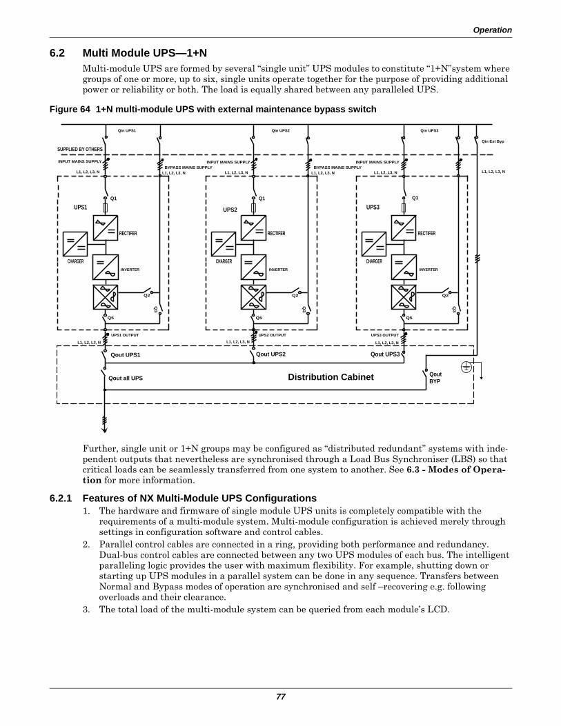
Operation
77
6.2 Multi Module UPS—1+NMulti-module UPS are formed by several “single unit” UPS modules to constitute “1+N”system where groups of one or more, up to six, single units operate together for the purpose of providing additional power or reliability or both. The load is equally shared between any paralleled UPS.
Figure 64 1+N multi-module UPS with external maintenance bypass switch
Further, single unit or 1+N groups may be configured as “distributed redundant” systems with inde-pendent outputs that nevertheless are synchronised through a Load Bus Synchroniser (LBS) so that critical loads can be seamlessly transferred from one system to another. See 6.3 - Modes of Opera-tion for more information.
6.2.1 Features of NX Multi-Module UPS Configurations1. The hardware and firmware of single module UPS units is completely compatible with the
requirements of a multi-module system. Multi-module configuration is achieved merely through settings in configuration software and control cables.
2. Parallel control cables are connected in a ring, providing both performance and redundancy. Dual-bus control cables are connected between any two UPS modules of each bus. The intelligent paralleling logic provides the user with maximum flexibility. For example, shutting down or starting up UPS modules in a parallel system can be done in any sequence. Transfers between Normal and Bypass modes of operation are synchronised and self –recovering e.g. following overloads and their clearance.
3. The total load of the multi-module system can be queried from each module’s LCD.
Distribution Cabinet
Qout UPS2 Qout UPS1
Qout all UPS
UPS3
SUPPLIED BY OTHERS
L1, L2, L3, N L1, L2, L3, N L1, L2, L3, N
UPS3 OUTPUT UPS2 OUTPUT UPS1 OUTPUT
L1, L2, L3, N L1, L2, L3, N L1, L2, L3, N
Qin Ext Byp
Qin UPS3 Qin UPS2 Qin UPS1
Q1 Q1
CHARGER
UPS2
INPUT MAINS SUPPLY BYPASS MAINS SUPPLY
L1, L2, L3, N L1, L2, L3, N
INPUT MAINS SUPPLY BYPASS MAINS SUPPLY
L1, L2, L3, N
INPUT MAINS SUPPLY
RECTIFER
INVERTER
Q5
Q3
Q2
Qout UPS3
Qout BYP
CHARGER
RECTIFER
INVERTER
Q5
Q3
Q2
UPS1 Q1
CHARGER
RECTIFER
INVERTER
Q5
Q3
Q2
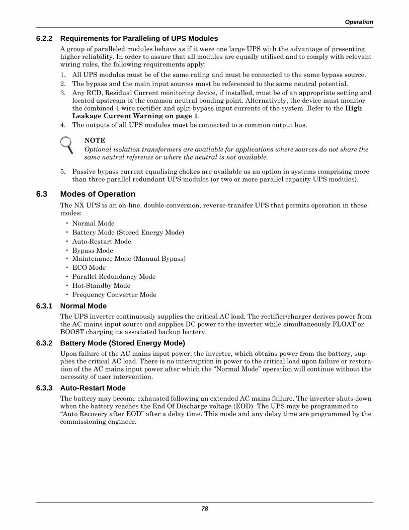
Operation
78
6.2.2 Requirements for Paralleling of UPS ModulesA group of paralleled modules behave as if it were one large UPS with the advantage of presenting higher reliability. In order to assure that all modules are equally utilised and to comply with relevant wiring rules, the following requirements apply:
1. All UPS modules must be of the same rating and must be connected to the same bypass source.2. The bypass and the main input sources must be referenced to the same neutral potential.3. Any RCD, Residual Current monitoring device, if installed, must be of an appropriate setting and
located upstream of the common neutral bonding point. Alternatively, the device must monitor the combined 4-wire rectifier and split-bypass input currents of the system. Refer to the High Leakage Current Warning on page 1.
4. The outputs of all UPS modules must be connected to a common output bus.
5. Passive bypass current equalising chokes are available as an option in systems comprising more than three parallel redundant UPS modules (or two or more parallel capacity UPS modules).
6.3 Modes of OperationThe NX UPS is an on-line, double-conversion, reverse-transfer UPS that permits operation in these modes:
• Normal Mode• Battery Mode (Stored Energy Mode)• Auto-Restart Mode• Bypass Mode• Maintenance Mode (Manual Bypass)• ECO Mode• Parallel Redundancy Mode• Hot-Standby Mode• Frequency Converter Mode
6.3.1 Normal ModeThe UPS inverter continuously supplies the critical AC load. The rectifier/charger derives power from the AC mains input source and supplies DC power to the inverter while simultaneously FLOAT or BOOST charging its associated backup battery.
6.3.2 Battery Mode (Stored Energy Mode) Upon failure of the AC mains input power; the inverter, which obtains power from the battery, sup-plies the critical AC load. There is no interruption in power to the critical load upon failure or restora-tion of the AC mains input power after which the “Normal Mode” operation will continue without the necessity of user intervention.
6.3.3 Auto-Restart ModeThe battery may become exhausted following an extended AC mains failure. The inverter shuts down when the battery reaches the End Of Discharge voltage (EOD). The UPS may be programmed to “Auto Recovery after EOD” after a delay time. This mode and any delay time are programmed by the commissioning engineer.
NOTEOptional isolation transformers are available for applications where sources do not share the same neutral reference or where the neutral is not available.
Operation
79
6.3.4 Bypass ModeIf the inverter overload capacity is exceeded, or if the inverter becomes unavailable for any reason, the static transfer switch will perform a transfer of the load from the inverter to the bypass source, with no interruption in power to the critical AC load. Should the inverter be asynchronous with the bypass, the static switch will perform a transfer of the load from the inverter to the bypass with inter-ruption in power to critical AC load. This is to avoid paralleling of unsynchronised AC sources. This interruption is programmable but typically set to be less than 3/4 of an electrical cycle, e.g., less than 15ms (50Hz) or less than 12.5ms (60Hz).
6.3.5 Maintenance Mode (Manual Bypass)A manual bypass switch is available to ensure continuity of supply to the critical load when the UPS becomes unavailable e.g. during a maintenance procedure. This manual bypass switch is fitted in all UPS modules and rated for full load of one module.
6.3.6 ECO Mode (Single UPS Only)If ECO mode is selected, the double-conversion UPS operation is inhibited at most times for the pur-pose of saving energy. In this mode of operation, not unlike UPS of line-interactive or stand-by tech-nology, the bypass is the preferred source and only when the voltage and / or frequency of the bypass supply are beyond pre-defined and adjustable limits the critical AC load is transferred to the inverter. This transfer takes place with an interruption of less than 3/4 of an electrical cycle, e.g., less than 15ms (50Hz) or less than 12.5ms (60Hz).
6.3.7 Parallel Redundancy Mode (System Expansion)For higher capacity or higher reliability or both, the outputs of up to six UPS modules can pro-grammed for directly paralleling while a built-in parallel controller in each UPS ensures automatic load sharing.
6.3.8 Hot-Standby ModeThis is an alternative 1+1 redundancy application that ensures higher availability or better usage control or both. Two UPS are connected in Hot Stand By mode as follows: UPS 1connects to the criti-cal load, and UPS 2 connects to the bypass of UPS 1. The remaining AC inputs are connected to the incoming AC mains supply. UPS 1 synchronises to the output of the UPS 2 ensuring uninterrupted load transfer from UPS 1 to UPS 2 or vice versa. This ensures that any specified load is supplied by a UPS while still providing a bypass path to cater for overloads. Further, the system can also be pro-grammed to reverse UPS1 between Normal and Bypass Modes so that each UPS is equally utilised. This interval is programmable from 1 to 4,320 hours (180 days).
6.3.9 Frequency Converter ModeThe NX UPS can be programmed into frequency converter mode for either 50Hz or 60Hz stable out-put frequency. The input frequency may vary from 40Hz to 70Hz. In this mode the static bypass oper-ation is disabled, and the battery becomes optional depending on any requirement to operate in battery mode (stored energy mode).
6.3.10 Source Share Mode (Co-Generation)NXa modules have the capability of fully supporting their critical load while limiting the amount of power taken from the incoming AC mains supply. Any balance of power required is supplied by the UPS battery. This feature is useful e.g. in applications where peak-hour tariffs apply or where a gen-erator smaller than needed feeds the UPS during mains outages. The Source Share Mode is user-acti-vated and the ratio of the main AC input power is programmable from 20% to 100% of the rated UPS power.
Operation
80
6.4 Battery Management—Set During Commissioning
6.4.1 Normal Function• Constant charging current—Current can be set up to limit charging power.• Constant boost voltage (if applicable)—Voltage of boost charging can be set as required by the
type of battery.For Valve Regulated Lead Acid (VRLA) batteries, maximum boost charge voltage should not exceed 2.4V / cell.
• Float Charge—Voltage of float charging can be set as required by the type of battery.For VRLA, float charge voltage should be between 2.2V to 2.3V.
• Float Charge Temperature Compensation (optional)—A coefficient of temperature compen-sation can be as required by the type of battery.
• End of discharge protection (EOD)—If the battery voltage is lower than the EOD, the battery converter will shut down and the battery is isolated to avoid further battery discharge. EOD is adjustable from 1.6V to 1.75V per cell (VRLA) or 0.9 to 1.1 V per cell (NiCd).
• Battery Low Warning Time—Adjustable between 3 and 60 minutes. The default is 5 minutes.
6.4.2 Advanced Functions (Software Settings Performed by the Commissioning Engineer)
Battery Self-Test and Self-ServiceAt periodic intervals 20% of the rated capacity of the battery will be discharged automatically at a rate equal to 15% (kW) of the rated UPS (kVA) capacity. During discharge the rectifier provides the balance necessary to feed the load. The minimum amount of load must exceed 20% of the nominal rat-ing of the UPS module. If the load is less than 20%, auto-discharge cannot be executed. The periodic interval can be set from 30 to 360 days. The periodic testing can also be inhibited.
• Conditions—Battery at float charge for at least 5 hours, load 20~100% of rated UPS capacity• Trigger—Manually through the command of Battery Maintenance Test in LCD panel or auto-
matically• Battery Self-Test Interval—30-360 days (default setting is 60 days)
6.5 Battery Protection (settings by commissioning engineer)Battery Undervoltage Pre-warning
The battery undervoltage pre-warning occurs before the end of discharge. After this pre-warning, the battery should have the capacity for 3 remaining minutes discharging with full load. The time is user configured from 3 to 60 minutes.
Battery End of Discharging (EOD) Protection
If the battery voltage is lower than the EOD, the battery converter will be shut down. EOD is adjust-able from 1.6V to 1.75V per VRLA cell (or 1.0 to 1.1 V per NiCd cell).
Battery Contactor Fault Warning
If the battery contactor monitor status is different from the drive signal, this warning will occur.
Battery Disconnect Devices
For 30- 40kVA models with internal batteries and for any model fitted with a Battery Start kit, the UPS contains an internal contactor for automatic connection and disconnection of the batteries. The relevant features are:
• Low battery safety cutoff• Connect/disconnect status displayed via LCD• Overcurrent protection• Maximum discharging time protection (1 to 72 hours)
For models above 40kVA and not fitted with an internal contactor: The features above (except automatic connect) are performed by connecting the external battery to the UPS through an external battery circuit breaker, which is manually closed and electronically tripped via the UPS control circuits.
Operating Procedures
81
7.0 OPERATING PROCEDURES
7.1 IntroductionFollowing installation and commissioning by an authorised service engineer, the UPS will operate in one of the modes described in 6.3 - Modes of Operation. This chapter describes the various proce-dures available for the operator to intervene with the UPS mode of operation including starting up, transferring load to bypass and shutting down.
7.2 Startup in Normal ModeThis procedure must be followed when turning on the UPS from a fully powered down condition - i.e., where the load is not being initially supplied at all or where supplied by the maintenance bypass switch. It is assumed that the installation is complete, the system has been commissioned by autho-rized personnel and the external power isolators are closed.
! WARNINGHazardous mains and / or battery voltage present behind covers.
No user-serviceable parts are located behind covers that require a tool for their removal. Only qualified service personnel are authorised to remove such covers.
NOTEAll the user controls and indicators mentioned in these procedures are identified in 8.0 - Operator Control Panel and Display.
All power switches mounted inside the cabinet and accessible after opening the key-locked front door are shown in Figure 63 and described in 7.0 - Operating Procedures.
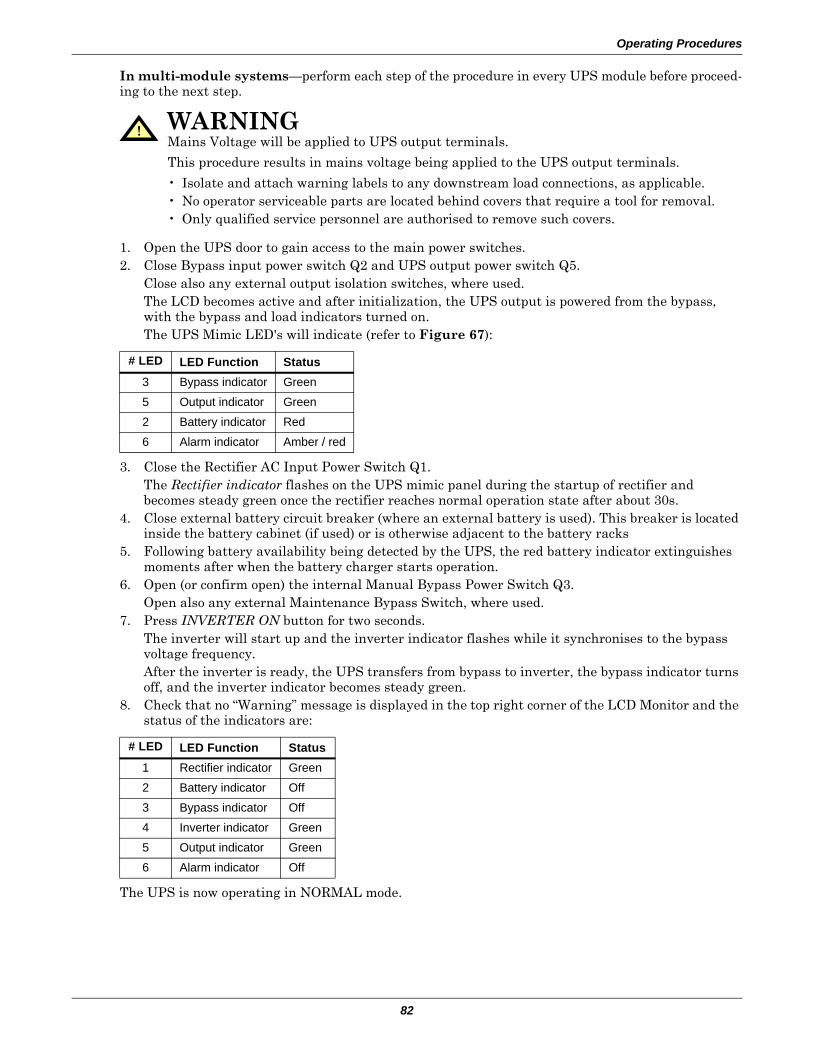
Operating Procedures
82
In multi-module systems—perform each step of the procedure in every UPS module before proceed-ing to the next step.
1. Open the UPS door to gain access to the main power switches.2. Close Bypass input power switch Q2 and UPS output power switch Q5.
Close also any external output isolation switches, where used.The LCD becomes active and after initialization, the UPS output is powered from the bypass, with the bypass and load indicators turned on.The UPS Mimic LED's will indicate (refer to Figure 67):
3. Close the Rectifier AC Input Power Switch Q1.The Rectifier indicator flashes on the UPS mimic panel during the startup of rectifier and becomes steady green once the rectifier reaches normal operation state after about 30s.
4. Close external battery circuit breaker (where an external battery is used). This breaker is located inside the battery cabinet (if used) or is otherwise adjacent to the battery racks
5. Following battery availability being detected by the UPS, the red battery indicator extinguishes moments after when the battery charger starts operation.
6. Open (or confirm open) the internal Manual Bypass Power Switch Q3.Open also any external Maintenance Bypass Switch, where used.
7. Press INVERTER ON button for two seconds.The inverter will start up and the inverter indicator flashes while it synchronises to the bypass voltage frequency.After the inverter is ready, the UPS transfers from bypass to inverter, the bypass indicator turns off, and the inverter indicator becomes steady green.
8. Check that no “Warning” message is displayed in the top right corner of the LCD Monitor and the status of the indicators are:
The UPS is now operating in NORMAL mode.
! WARNINGMains Voltage will be applied to UPS output terminals.
This procedure results in mains voltage being applied to the UPS output terminals.
• Isolate and attach warning labels to any downstream load connections, as applicable.• No operator serviceable parts are located behind covers that require a tool for removal.• Only qualified service personnel are authorised to remove such covers.
# LED LED Function Status3 Bypass indicator Green5 Output indicator Green2 Battery indicator Red6 Alarm indicator Amber / red
# LED LED Function Status1 Rectifier indicator Green2 Battery indicator Off3 Bypass indicator Off4 Inverter indicator Green5 Output indicator Green6 Alarm indicator Off
Operating Procedures
83
7.3 Startup into ECO ModeApplies only to a single module UPS and when programmed by the commissioning engineer to per-form ECO mode control of the power delivered to the load.
Follow 7.2 - Startup in Normal Mode and observe at the end of the procedure that the mimic panel bypass indicator remains green (indicating that the load is supplied by the bypass mains).
The UPS is now operating in ECOMODE.
7.4 Battery Test Mode ProceduresThe Battery test mode procedures transfer the UPS into shared source mode wherein approximately 15% of the rated load power is supplied by the battery and the balance by the AC input mains. There are two Battery tests to select from:
Maintenance test—verifies battery integrity and leads to a 20-percent battery discharge.
Battery Capacity test—verifies the battery’s precise capacity and leads to a full battery discharge (until “Battery Low” alarm).
The battery test procedures are password-controlled and menu-driven. The test is immediately termi-nated in the event of a battery or a mains failure and the total load power is supported from the remaining source without interruptions.
The tests can be carried out from the UPS control panel by the operator when the following conditions are satisfied:
• The load must be between 20% and 100% of rated UPS capacity• The battery must have been float charging for 5 hours or more.
7.4.1 Test Procedure1. Select “Commands” window on the UPS control panel.
Use the right or left arrow keys to navigate to the “Commands” window.2. Select desired Test.
Use “page” (F1) and up / down arrow keys (F2, F3) to highlight the desired test. Press “enter” (F4). When prompted, enter each password digit with up arrow (F2) and use right arrow (F3) to access next field. Press “enter” (F4) when all digits have been entered.
3. Wait until the test completes.This tests updates the battery information used to calculate the expected back-up time (displayed during AC input failure) and the battery capacity percentage when compared to a new battery (displayed in normal mode).
4. Stop test.If required, the test may be stopped before completion by selecting “Stop Test” in the “Commands” window.
For more details on how to operate the UPS control panel refer to 8.0 - Operator Control Panel and Display.
Operating Procedures
84
7.5 UPS Self-Test The UPS test procedure checks the control functions of the UPS, the mimic flow chart LEDs and the audible alarm. This self-test is password controlled and menu driven. It can be carried out from the UPS front panel by the operator and takes 5 seconds.
7.5.1 UPS Self-Test Procedure1. Select “Commands” window on the UPS front panel.
Use the right or left arrow keys to navigate to the “Commands” window2. Select desired Test.
Use “page” (F1) and up / down arrow keys (F2, F3) to highlight the desired test. Press “enter” (F4). When prompted, enter each password digit with up arrow (F2) and use right arrow (F3) to access next field. Press “enter” (F4) when all digits have been entered.
3. Wait until the test completes.After 5 seconds, a popup window will appear to showing the result of this diagnosis: Rectifier, Inverter, Monitor OK or Fault
4. Stop test.If required, the test may be stopped before completion by selecting “Stop Test” in the “Commands” window.
For more details on operating the UPS front panel, see 8.0 - Operator Control Panel and Display.
7.6 Maintenance Bypass Procedure and UPS ShutdownThe following procedure transfers the load supply from being protected by the UPS into being connected directly to the AC input bypass supply though a maintenance bypass switch. This switch is either:
• internal (Q3- located behind the front door) for “Single module” or “1+1 redundant multi-module” UPS applications.
• external (located in the bypass cabinet) for “1+1 capacity” and “1+N redundant” multi-module UPS applications – refer to Figure 64.
In multi-module systems—perform each step of the procedure in every UPS module before proceed-ing to the next step.
1. Press INVERTER OFF direct access key on the UPS front panel.The UPS inverter will shut down and the load is supplied through the Static Bypass supply.The UPS Mimic indicator Inverter ON (4) will extinguish, the Status LED (6) turns on.
2. In “Single module” or “1+1 redundant” multi-module UPS—Close the internal maintenance bypass power switch Q3 and any external maintenance bypass switch, if used.
3. In “1+N redundant” or “1+1 capacity” multi-module UPS—Close the external maintenance switch only.
4. The Maintenance Bypass supply is now in parallel with the UPS Static Switch supply.5. The display window will show messages reflecting the actions taken (i.e. Maintenance Bypass
closed, etc.).6. Open output power switch Q5.
This ends the Bypass Procedure. The load is now powered directly from the Maintenance Bypass supply.
Proceed with the following steps to shutdown the rectifier and battery.
! CAUTIONRisk of Load Interruption
Except in emergency situations, so as not to risk a short interruption in powering the load, before initiating this bypass procedure, confirm that no WARNING status is displayed in the top right corner of the UPS Monitor.
If a WARNING status is displayed, the operator will be prompted to confirm (“enter”) or cancel (“ESC”) any action that can lead to load interruption.
NOTEThe load equipment is NOT protected from AC supply aberrations.
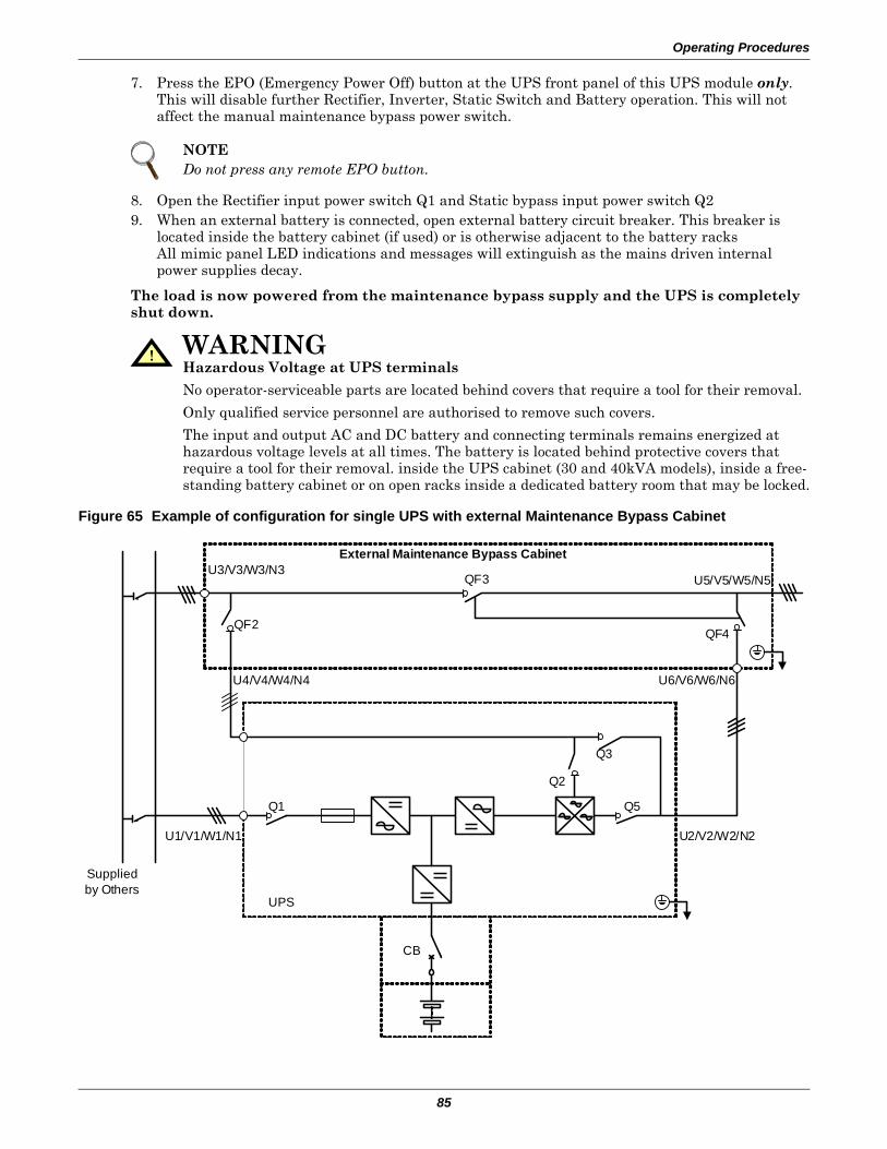
Operating Procedures
85
7. Press the EPO (Emergency Power Off) button at the UPS front panel of this UPS module only. This will disable further Rectifier, Inverter, Static Switch and Battery operation. This will not affect the manual maintenance bypass power switch.
8. Open the Rectifier input power switch Q1 and Static bypass input power switch Q29. When an external battery is connected, open external battery circuit breaker. This breaker is
located inside the battery cabinet (if used) or is otherwise adjacent to the battery racksAll mimic panel LED indications and messages will extinguish as the mains driven internal power supplies decay.
The load is now powered from the maintenance bypass supply and the UPS is completely shut down.
Figure 65 Example of configuration for single UPS with external Maintenance Bypass Cabinet
NOTEDo not press any remote EPO button.
! WARNINGHazardous Voltage at UPS terminals
No operator-serviceable parts are located behind covers that require a tool for their removal.
Only qualified service personnel are authorised to remove such covers.
The input and output AC and DC battery and connecting terminals remains energized at hazardous voltage levels at all times. The battery is located behind protective covers that require a tool for their removal. inside the UPS cabinet (30 and 40kVA models), inside a free-standing battery cabinet or on open racks inside a dedicated battery room that may be locked.
Q1
UPS
Supplied by Others
CB
U5/V5/W5/N5U3/V3/W3/N3
U1/V1/W1/N1
U4/V4/W4/N4
U2/V2/W2/N2
U6/V6/W6/N6
Q3
Q5
Q2
QF2QF4
QF3
External Maintenance Bypass Cabinet
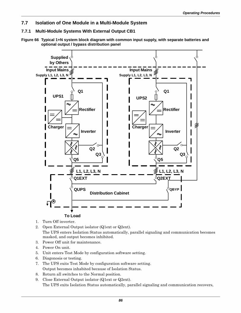
Operating Procedures
86
7.7 Isolation of One Module in a Multi-Module System
7.7.1 Multi-Module Systems With External Output CB1
Figure 66 Typical 1+N system block diagram with common input supply, with separate batteries and optional output / bypass distribution panel
1. Turn Off inverter.2. Open External Output isolator (Q1ext or Q2ext).
The UPS enters Isolation Status automatically, parallel signaling and communication becomes masked, and output becomes inhibited.
3. Power Off unit for maintenance.4. Power On unit.5. Unit enters Test Mode by configuration software setting.6. Diagonosis or testing.7. The UPS exits Test Mode by configuration software setting.
Output becomes inhabited because of Isolation Status.8. Return all switches to the Normal position.9. Close External Output isolator (Q1ext or Q2ext).
The UPS exits Isolation Status automatically, parallel signaling and communication recovers,
To Load
Distribution Cabinet
Supplied by Others
Input MainsSupply L1, L2, L3, N
UPS1 UPS2Q1
Rectifier
InverterCharger
Q2Q3
Q5
Q2Q3
Q5
Rectifier
InverterCharger
Q1
Input MainsSupply L1, L2, L3, N
L1, L2, L3, NL1, L2, L3, N
QUPS QBYP
Q1EXT Q2EXT
Operating Procedures
87
output becomes enabled but interlocking works now.10. Turn On inverter and join the parallel system.
7.7.2 Multi-Module System Without External Output Circuit Breaker 1This procedure is indicated for isolation of one UPS module from other modules of a group of other-wise normally operating paralleled UPS modules. Only the power switches, isolators and circuit breakers in the module to be isolated will be opened. This procedure does not require the supply of any bypass power to the critical load.
1. Turn Off the inverter2. Open Internal Output isolator (Q5) but keep Internal Maintenance Circuit Breaker open.
The UPS enters Isolation Status automatically, parallel signaling and communication become masked, and internal output becomes inhibited.
3. Power Off unit for maintenance.4. Power On unit with Internal Output isolator (Q5) open.5. The UPS enters Test Mode by configuration software setting.6. Diagonosis or testing.7. The UPS exits Test Mode by configuration software setting.
Output becomes inhibited because of Isolation Status.8. Return all switches of Unit 1 to the Normal position, including Internal Output Circuit Breaker 1.
When Internal Output isolator (Q5) is closed, unit will exit Isolation Status automatically, parallel signaling and communication recovers, output becomes enabled but interlocking works now.
9. Turn On Inverter1 and join the parallel system.
! WARNINGHazardous Battery Voltage
No operator serviceable parts are located behind covers that require a tool for their removal.
Only qualified service personnel are authorised to remove such covers.
The UPS battery and connecting terminals remains energized at hazardous voltage levels at all times. The battery is located behind protective covers that require a tool for their removal: inside the UPS cabinet (30 and 40kVA models), inside a free-standing battery cabinet or on open racks inside a dedicated battery room that may be locked.
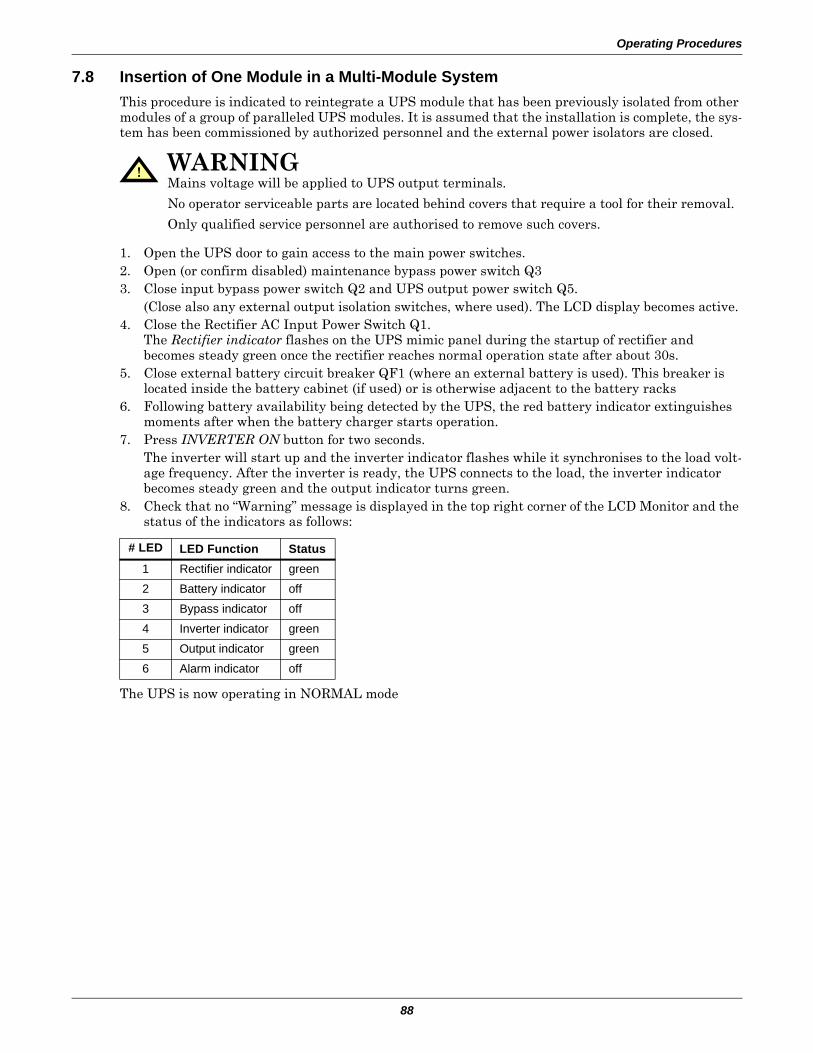
Operating Procedures
88
7.8 Insertion of One Module in a Multi-Module SystemThis procedure is indicated to reintegrate a UPS module that has been previously isolated from other modules of a group of paralleled UPS modules. It is assumed that the installation is complete, the sys-tem has been commissioned by authorized personnel and the external power isolators are closed.
1. Open the UPS door to gain access to the main power switches. 2. Open (or confirm disabled) maintenance bypass power switch Q33. Close input bypass power switch Q2 and UPS output power switch Q5.
(Close also any external output isolation switches, where used). The LCD display becomes active. 4. Close the Rectifier AC Input Power Switch Q1.
The Rectifier indicator flashes on the UPS mimic panel during the startup of rectifier and becomes steady green once the rectifier reaches normal operation state after about 30s.
5. Close external battery circuit breaker QF1 (where an external battery is used). This breaker is located inside the battery cabinet (if used) or is otherwise adjacent to the battery racks
6. Following battery availability being detected by the UPS, the red battery indicator extinguishes moments after when the battery charger starts operation.
7. Press INVERTER ON button for two seconds.The inverter will start up and the inverter indicator flashes while it synchronises to the load volt-age frequency. After the inverter is ready, the UPS connects to the load, the inverter indicator becomes steady green and the output indicator turns green.
8. Check that no “Warning” message is displayed in the top right corner of the LCD Monitor and the status of the indicators as follows:
The UPS is now operating in NORMAL mode
! WARNINGMains voltage will be applied to UPS output terminals.
No operator serviceable parts are located behind covers that require a tool for their removal.
Only qualified service personnel are authorised to remove such covers.
# LED LED Function Status1 Rectifier indicator green2 Battery indicator off3 Bypass indicator off4 Inverter indicator green5 Output indicator green6 Alarm indicator off
Operating Procedures
89
7.9 Shutdown Procedure—Complete UPS and Load ShutdownThis procedure must be followed to completely power down the UPS and LOAD. All power switches, isolators and circuit breakers will be opened and power will be removed from the load.
In multi-module systems – perform each step of the procedure in every UPS module before proceeding to the next step.
1. Press the EPO (Emergency Power Off) button at the UPS front panel only. This will disable Rectifier, Inverter, Static Switch and Battery operation. The Load will be de-energised.
2. Open the UPS door to gain access to the main power switches.3. Open the Rectifier input power switch Q14. Open external battery circuit breaker (where an external battery is used). This breaker is located
inside the battery cabinet (if used) or is otherwise adjacent to the battery racks 5. Open Output power switch Q56. Open bypass input power switch Q27. Ensure maintenance bypass power switch Q3 is open.8. All mimic panel LED indications and messages will extinguish as the mains driven internal
power supplies decay.9. To completely isolate the UPS from the AC supplies, the main external power input isolator (both
isolators, where split supplies are provided for rectifier and bypass) and external output isolator must be opened and tagged with warning labels accordingly.
7.10 Emergency Shutdown With EPOThis circuit has been designed to switch off the UPS in emergency conditions (i.e., fire, flood, etc.). The system will turn off the rectifier, inverter and stop powering the load immediately (including the inverter and bypass), and the battery stops charging or discharging.
If the input utility is present, the UPS’s controls will remain active; however, the output will be turned off. To remove all power from the UPS, the external feeder breaker should be opened.
! CAUTIONThe following procedure will switch off all power to the load equipment.
NOTEExcept in an emergency situation, do not press any remote EPO button.
! WARNINGHazardous Battery Voltage
No operator serviceable parts are located behind covers that require a tool for their removal.
Only qualified service personnel are authorised to remove such covers.
The UPS battery and connecting terminals remains energized at hazardous voltage levels at all times. The battery is located behind protective covers that require a tool for their removal: inside the UPS cabinet (30 and 40kVA models), inside a free-standing battery cabinet or on open racks inside a dedicated battery room that may be locked.
Operating Procedures
90
7.11 Reset After Shutdown for Emergency Stop (EPO Action) or Other ConditionsOnce all appropriate measures have been taken to correct the problem indicated by the alarm mes-sage appearing on the operator control panel display, carry out this procedure to restore the UPS to regular operation following an EPO action or for the following reasons: Inverter Overtemperature, Cut-off Overload, Battery Overvoltage, excessive switching (BYP: XFER COUNT BLOCK), etc.
When the user confirms that the fault is cleared & the remote EPO signal is not active:
1. Press the FAULT CLEAR button to let the system exit the Emergency Off state.2. Press the INVERTER ON button on the right side of the operator control panel for longer than
2 seconds.
After the EPO button is pressed, if the input utility is removed, the UPS will shut down completely.
When input utility returns, if the Bypass input power switch (Q2) and UPS output power switch (Q5) are closed, the UPS will startup on Bypass. There will be power at the output terminals of the UPS.
7.12 Auto RestartWhen the main and bypass sources fail, the UPS draws power from the battery system to supply the load until the batteries are depleted. When the UPS reaches its end of discharge (EOD) threshold, it will shut down.
The UPS will automatically restart and enable output power:
• After utility power is restored• If “Auto Recovery after EOD Enabling” is enabled• After the “Auto Recovery after EOD Delay Time” expires (the default delay is 10 minutes) .
If the “Auto Recovery after EOD Enabling” feature is disabled, the user may restart the system man-ually by pressing “Fault Clear” button.
NOTE: UPS manufactured before March 2006 may first require a full power down, i.e., manual opening of the input isolators, for the "Fault Clear" to take effect
NOTEThe rectifier will start again, and the bypass will begin to power the load (for units with internal battery contactor installed, the battery contactor will close). The Rectifier indicator flashes while the rectifier is starting up. When the rectifier enters the normal operation state (about 30 seconds), the rectifier indicator turns green.
NOTEThe rectifier will be turned On automatically when the overtemperature fault disappears at 5 minutes after the disappearance of overtemperature signals.
! WARNINGIf the internal Manual Bypass Power Switch (Q3) is closed and input utility is present, there will be power at the output terminals of the UPS.
Operating Procedures
91
7.13 Language SelectionThe LCD menus and data display are available in 12 languages: Chinese, Dutch, English, French, German, Italian, Japanese, Polish, Portuguese, Russian, Spanish and Swedish.To select a different language than the one being displayed:
1. From the main menu, press the F1 (shift) key to move the cursor to the menu at the top of the screen.
2. Press F2 and F3 (left and right arrows) as needed to select the Language menu.3. Press F1 (shift) to move the cursor to the data and settings area of the LCD.4. Use F2 and F3 (up and down) to select the required language.5. Press the F4 (enter) key to accept the language selection.6. Return to the main menu by repeatedly pressing F1 (ESC) as needed; all text on the LCD will now
be displayed in the selected language.
7.14 Changing the Current Date and TimeTo change the system date and time:1. From the main menu, press the F1 (shift) key to move the cursor to the menu at the top of the
screen.2. Press F2 and F3 (left and right arrows) as needed to select the Settings menu.3. Press F1 (shift) to move the cursor to the data and settings area of the LCD.4. Use F2 and F3 (up and down) to select the Date & Time option, then press F4 (enter).5. Position the cursor on the row in which the date and time are displayed, then press F4 (enter).6. Using the F2 and F3 (up and down) keys, enter the current time and date information.7. Press F4 (enter) to save the settings, then press F1 (ESC) to return to the main menu.
7.15 Command PasswordPassword protection is used to limit the control functions accessible to the operator. The default pass-word is 12345. This password provides access to UPS and battery test functions.
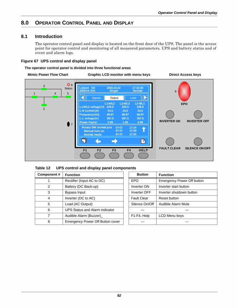
Operator Control Panel and Display
92
8.0 OPERATOR CONTROL PANEL AND DISPLAY
8.1 IntroductionThe operator control panel and display is located on the front door of the UPS. The panel is the access point for operator control and monitoring of all measured parameters, UPS and battery status and of event and alarm logs.
Figure 67 UPS control and display panel
Table 12 UPS control and display panel componentsComponent # Function Button Function
1 Rectifier (Input AC to DC) EPO Emergency Power Off button2 Battery (DC Back-up) Inverter ON Inverter start button3 Bypass Input Inverter OFF Inverter shutdown button4 Inverter (DC to AC) Fault Clear Reset button5 Load (AC Output) Silence On/Off Audible Alarm Mute6 UPS Status and Alarm indicator — —7 Audible Alarm (Buzzer)_ F1-F4, Help LCD Menu keys8 Emergency Power Off Button cover — —
EPO
INVERTER ON
FAULT CLEAR SILENCE ON/OFF
3
1
2
4 5
Status
?
Rotary SW. normal pos. 17:2407-07Manual turn onNormal mode
17:2917:30
07-0707-07
7
8
6
INVERTER OFF
F2 F3 F4 HELPF1
LoadBypass Output
Liebert NX200kVA 3X3
2005-10-22Single
17:32:20Normal
L1-N/L2229.524.549.97397.50.99
L2-N/L3229.524.549.97397.51.00
L3-N/L1229.524.549.97397.50.99
L1-N/L2 voltage (V)L-N current (A)Frequency (Hz)L-L voltage (V)Power Factor
The operator control panel is divided into three functional areas
Mimic Power Flow Chart Graphic LCD monitor with menu keys Direct Access keys
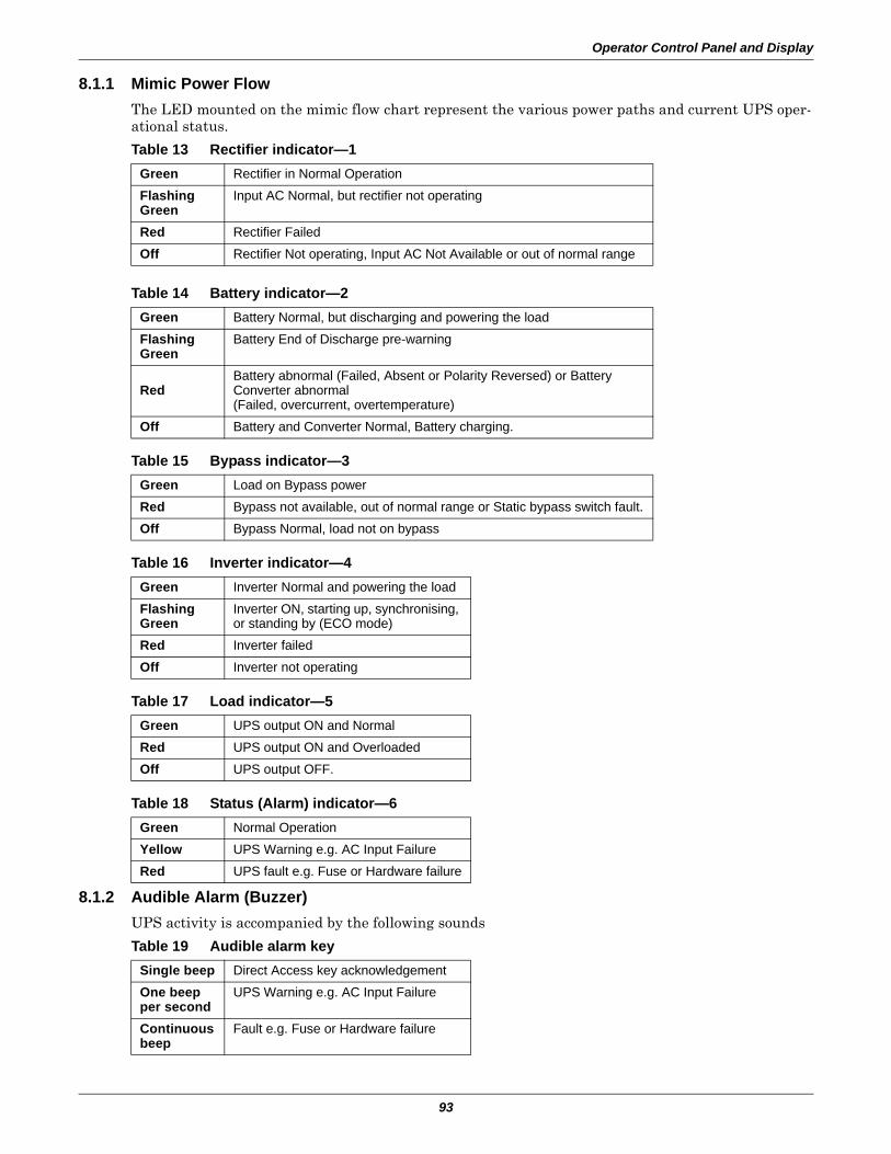
Operator Control Panel and Display
93
8.1.1 Mimic Power FlowThe LED mounted on the mimic flow chart represent the various power paths and current UPS oper-ational status.
8.1.2 Audible Alarm (Buzzer) UPS activity is accompanied by the following sounds
Table 13 Rectifier indicator—1Green Rectifier in Normal OperationFlashingGreen
Input AC Normal, but rectifier not operating
Red Rectifier FailedOff Rectifier Not operating, Input AC Not Available or out of normal range
Table 14 Battery indicator—2Green Battery Normal, but discharging and powering the loadFlashingGreen
Battery End of Discharge pre-warning
RedBattery abnormal (Failed, Absent or Polarity Reversed) or Battery Converter abnormal(Failed, overcurrent, overtemperature)
Off Battery and Converter Normal, Battery charging.
Table 15 Bypass indicator—3Green Load on Bypass powerRed Bypass not available, out of normal range or Static bypass switch fault.Off Bypass Normal, load not on bypass
Table 16 Inverter indicator—4Green Inverter Normal and powering the loadFlashingGreen
Inverter ON, starting up, synchronising, or standing by (ECO mode)
Red Inverter failedOff Inverter not operating
Table 17 Load indicator—5Green UPS output ON and NormalRed UPS output ON and OverloadedOff UPS output OFF.
Table 18 Status (Alarm) indicator—6Green Normal OperationYellow UPS Warning e.g. AC Input Failure Red UPS fault e.g. Fuse or Hardware failure
Table 19 Audible alarm keySingle beep Direct Access key acknowledgementOne beepper second
UPS Warning e.g. AC Input Failure
Continuousbeep
Fault e.g. Fuse or Hardware failure
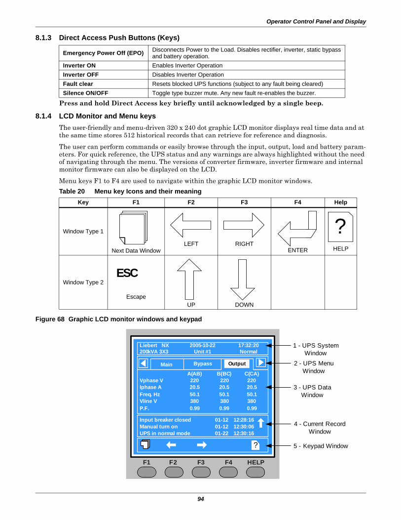
Operator Control Panel and Display
94
8.1.3 Direct Access Push Buttons (Keys)
Press and hold Direct Access key briefly until acknowledged by a single beep.
8.1.4 LCD Monitor and Menu keys The user-friendly and menu-driven 320 x 240 dot graphic LCD monitor displays real time data and at the same time stores 512 historical records that can retrieve for reference and diagnosis.
The user can perform commands or easily browse through the input, output, load and battery param-eters. For quick reference, the UPS status and any warnings are always highlighted without the need of navigating through the menu. The versions of converter firmware, inverter firmware and internal monitor firmware can also be displayed on the LCD.
Menu keys F1 to F4 are used to navigate within the graphic LCD monitor windows.
Figure 68 Graphic LCD monitor windows and keypad
Emergency Power Off (EPO) Disconnects Power to the Load. Disables rectifier, inverter, static bypassand battery operation.
Inverter ON Enables Inverter Operation Inverter OFF Disables Inverter Operation Fault clear Resets blocked UPS functions (subject to any fault being cleared)Silence ON/OFF Toggle type buzzer mute. Any new fault re-enables the buzzer.
Table 20 Menu key Icons and their meaningKey F1 F2 F3 F4 Help
Window Type 1
Next Data WindowLEFT RIGHT
ENTER HELP
Window Type 2
EscapeUP DOWN
?
ESC
Liebert NX200kVA 3X3
?
Output
2005-10-22Unit #1
17:32:20Normal
F2 F3 F4 HELPF1
BypassMainA(AB) B(BC) C(CA)
Vphase V 220 220 220Iphase A 20.5 20.5 20.5Freq. Hz 50.1 50.1 50.1Vline V 380 380 380P.F. 0.99 0.99 0.99
Input breaker closed 01-12 12:28:16Manual turn on 01-12 12:30:06UPS in normal mode 01-22 12:30:16
4 - Current Record Window
3 - UPS Data Window
2 - UPS Menu Window
1 - UPS System Window
5 - Keypad Window
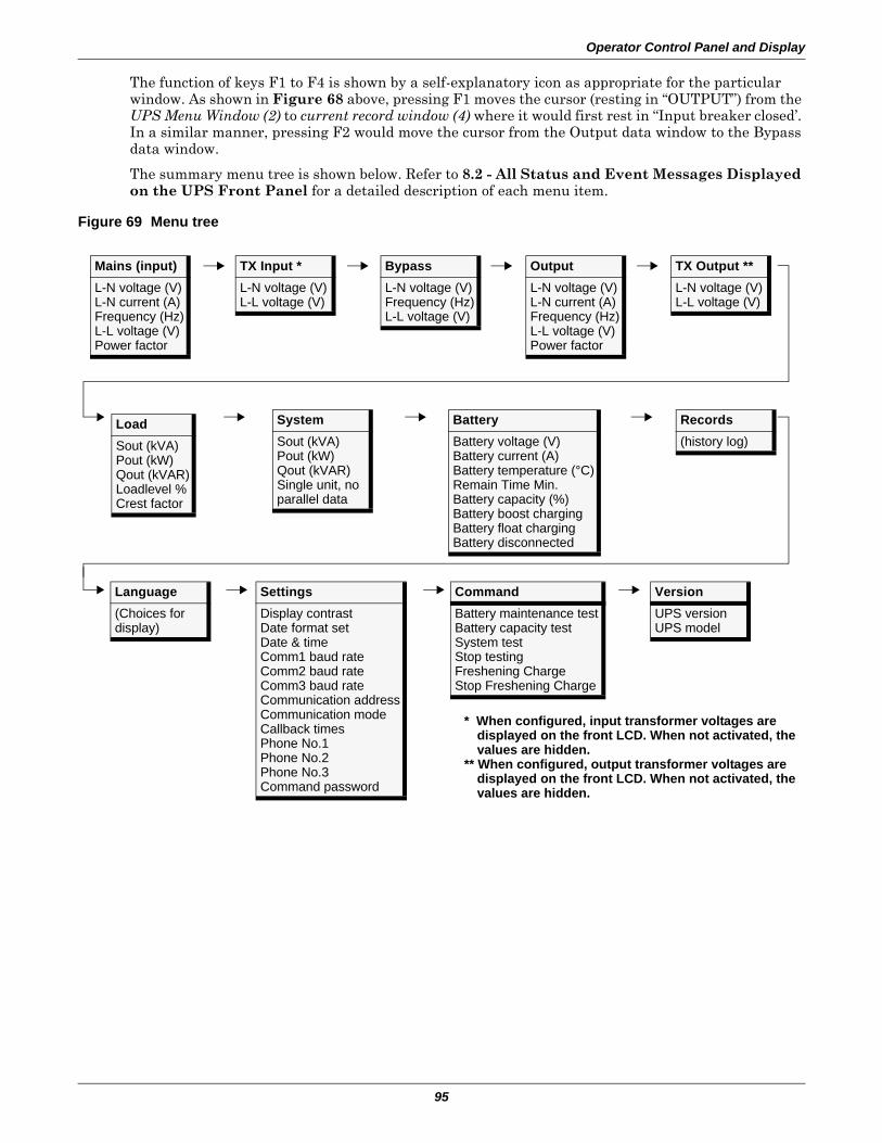
Operator Control Panel and Display
95
The function of keys F1 to F4 is shown by a self-explanatory icon as appropriate for the particular window. As shown in Figure 68 above, pressing F1 moves the cursor (resting in “OUTPUT”) from the UPS Menu Window (2) to current record window (4) where it would first rest in “Input breaker closed’. In a similar manner, pressing F2 would move the cursor from the Output data window to the Bypass data window.
The summary menu tree is shown below. Refer to 8.2 - All Status and Event Messages Displayed on the UPS Front Panel for a detailed description of each menu item.
Figure 69 Menu tree
BatteryBattery voltage (V)Battery current (A)Battery temperature (°C)Remain Time Min.Battery capacity (%)Battery boost chargingBattery float chargingBattery disconnected
CommandBattery maintenance testBattery capacity testSystem test Stop testingFreshening ChargeStop Freshening Charge
VersionUPS versionUPS model
SettingsDisplay contrastDate format setDate & timeComm1 baud rateComm2 baud rateComm3 baud rateCommunication addressCommunication modeCallback timesPhone No.1Phone No.2Phone No.3Command password
SystemSout (kVA)Pout (kW)Qout (kVAR)Single unit, no parallel data
Records(history log)
Language(Choices for display)
Mains (input)L-N voltage (V)L-N current (A)Frequency (Hz)L-L voltage (V)Power factor
LoadSout (kVA)Pout (kW)Qout (kVAR)Loadlevel %Crest factor
BypassL-N voltage (V)Frequency (Hz)L-L voltage (V)
OutputL-N voltage (V)L-N current (A)Frequency (Hz)L-L voltage (V)Power factor
TX Input *L-N voltage (V)L-L voltage (V)
* When configured, input transformer voltages are displayed on the front LCD. When not activated, the values are hidden.
** When configured, output transformer voltages are displayed on the front LCD. When not activated, the values are hidden.
TX Output **L-N voltage (V)L-L voltage (V)
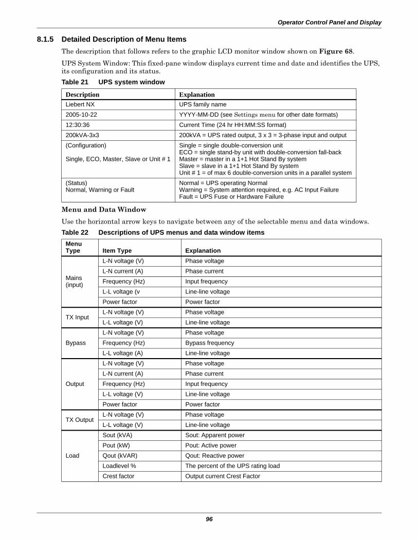
Operator Control Panel and Display
96
8.1.5 Detailed Description of Menu ItemsThe description that follows refers to the graphic LCD monitor window shown on Figure 68.
UPS System Window: This fixed-pane window displays current time and date and identifies the UPS, its configuration and its status.
Menu and Data Window
Use the horizontal arrow keys to navigate between any of the selectable menu and data windows.
Table 21 UPS system window
Description ExplanationLiebert NX UPS family name2005-10-22 YYYY-MM-DD (see Settings menu for other date formats)12:30:36 Current Time (24 hr HH:MM:SS format)200kVA-3x3 200kVA = UPS rated output, 3 x 3 = 3-phase input and output(Configuration)
Single, ECO, Master, Slave or Unit # 1
Single = single double-conversion unitECO = single stand-by unit with double-conversion fall-backMaster = master in a 1+1 Hot Stand By systemSlave = slave in a 1+1 Hot Stand By systemUnit # 1 = of max 6 double-conversion units in a parallel system
(Status)Normal, Warning or Fault
Normal = UPS operating NormalWarning = System attention required, e.g. AC Input FailureFault = UPS Fuse or Hardware Failure
Table 22 Descriptions of UPS menus and data window itemsMenuType Item Type Explanation
Mains(input)
L-N voltage (V) Phase voltageL-N current (A) Phase currentFrequency (Hz) Input frequencyL-L voltage (v Line-line voltagePower factor Power factor
TX InputL-N voltage (V) Phase voltageL-L voltage (V) Line-line voltage
BypassL-N voltage (V) Phase voltageFrequency (Hz) Bypass frequencyL-L voltage (A) Line-line voltage
Output
L-N voltage (V) Phase voltageL-N current (A) Phase currentFrequency (Hz) Input frequencyL-L voltage (V) Line-line voltagePower factor Power factor
TX OutputL-N voltage (V) Phase voltageL-L voltage (V) Line-line voltage
Load
Sout (kVA) Sout: Apparent powerPout (kW) Pout: Active powerQout (kVAR) Qout: Reactive powerLoadlevel % The percent of the UPS rating loadCrest factor Output current Crest Factor
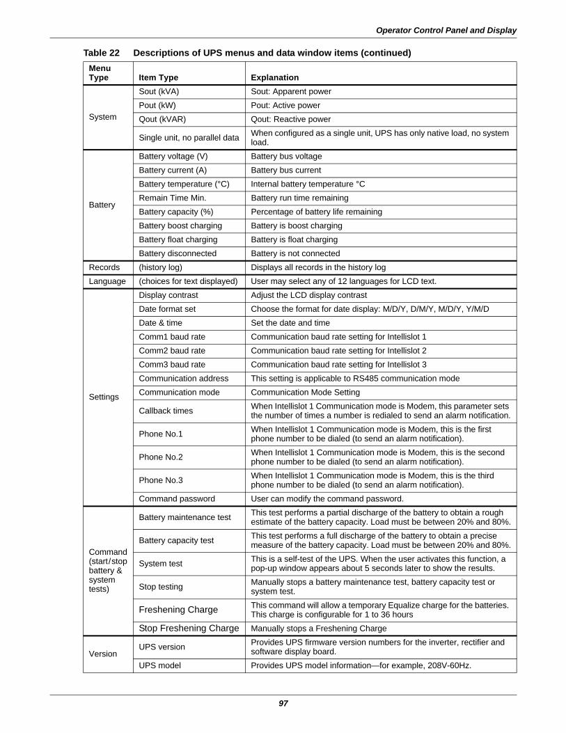
Operator Control Panel and Display
97
System
Sout (kVA) Sout: Apparent powerPout (kW) Pout: Active powerQout (kVAR) Qout: Reactive power
Single unit, no parallel data When configured as a single unit, UPS has only native load, no system load.
Battery
Battery voltage (V) Battery bus voltageBattery current (A) Battery bus currentBattery temperature (°C) Internal battery temperature °CRemain Time Min. Battery run time remainingBattery capacity (%) Percentage of battery life remainingBattery boost charging Battery is boost chargingBattery float charging Battery is float chargingBattery disconnected Battery is not connected
Records (history log) Displays all records in the history logLanguage (choices for text displayed) User may select any of 12 languages for LCD text.
Settings
Display contrast Adjust the LCD display contrastDate format set Choose the format for date display: M/D/Y, D/M/Y, M/D/Y, Y/M/DDate & time Set the date and timeComm1 baud rate Communication baud rate setting for Intellislot 1 Comm2 baud rate Communication baud rate setting for Intellislot 2 Comm3 baud rate Communication baud rate setting for Intellislot 3 Communication address This setting is applicable to RS485 communication modeCommunication mode Communication Mode Setting
Callback times When Intellislot 1 Communication mode is Modem, this parameter sets the number of times a number is redialed to send an alarm notification.
Phone No.1 When Intellislot 1 Communication mode is Modem, this is the first phone number to be dialed (to send an alarm notification).
Phone No.2 When Intellislot 1 Communication mode is Modem, this is the second phone number to be dialed (to send an alarm notification).
Phone No.3 When Intellislot 1 Communication mode is Modem, this is the third phone number to be dialed (to send an alarm notification).
Command password User can modify the command password.
Command(start/stopbattery &systemtests)
Battery maintenance test This test performs a partial discharge of the battery to obtain a rough estimate of the battery capacity. Load must be between 20% and 80%.
Battery capacity test This test performs a full discharge of the battery to obtain a precise measure of the battery capacity. Load must be between 20% and 80%.
System test This is a self-test of the UPS. When the user activates this function, a pop-up window appears about 5 seconds later to show the results.
Stop testing Manually stops a battery maintenance test, battery capacity test or system test.
Freshening Charge This command will allow a temporary Equalize charge for the batteries. This charge is configurable for 1 to 36 hours
Stop Freshening Charge Manually stops a Freshening Charge
VersionUPS version Provides UPS firmware version numbers for the inverter, rectifier and
software display board.UPS model Provides UPS model information—for example, 208V-60Hz.
Table 22 Descriptions of UPS menus and data window items (continued)MenuType Item Type Explanation
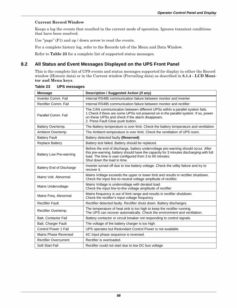
Operator Control Panel and Display
98
Current Record Window
Keeps a log the events that resulted in the current mode of operation. Ignores transient conditions that have been resolved.
Use “page” (F1) and up / down arrow to read the events.
For a complete history log, refer to the Records tab of the Menu and Data Window.
Refer to Table 23 for a complete list of supported status messages.
8.2 All Status and Event Messages Displayed on the UPS Front PanelThis is the complete list of UPS events and status messages supported for display in either the Record window (Historic data) or in the Current window (Prevailing data) as described in 8.1.4 - LCD Moni-tor and Menu keys.
Table 23 UPS messagesMessage Description / Suggested Action (if any)Inverter Comm. Fail Internal RS485 communication failure between monitor and inverterRectifier Comm. Fail Internal RS485 communication failure between monitor and rectifier
Parallel Comm. FailThe CAN communication between different UPSs within a parallel system fails.1.Check if there are some UPSs not powered on in the parallel system. If so, power on these UPSs and check if the alarm disappears.2. Press Fault Clear push button.
Battery Overtemp. The Battery temperature is over limit. Check the battery temperature and ventilationAmbient Overtemp. The Ambient temperature is over limit. Check the ventilation of UPS room.Battery Fault Battery detected faulty (Reserved)Replace Battery Battery test failed, Battery should be replaced.
Battery Low Pre-warningBefore the end of discharge, battery undervoltage pre-warning should occur. After this pre-warning, battery should have the capacity for 3 minutes discharging with full load. The time is user-configured from 3 to 60 minutes.Shut down the load in time.
Battery End of Discharge Inverter turned off due to low battery voltage. Check the utility failure and try to recover it.
Mains Volt. Abnormal Mains Voltage exceeds the upper or lower limit and results in rectifier shutdown.Check the input line-to-neutral voltage amplitude of rectifier.
Mains Undervoltage Mains Voltage is undervoltage with derated load.Check the input line-to-line voltage amplitude of rectifier
Mains Freq. Abnormal Mains frequency is out of limit range and results in rectifier shutdown.Check the rectifier’s input voltage frequency
Rectifier Fault Rectifier detected faulty. Rectifier shuts down. Battery discharges.
Rectifier Overtemp. The temperature of heat sink is too high to keep the rectifier running.The UPS can recover automatically. Check the environment and ventilation.
Batt. Contactor Fail Battery contactor or circuit breaker not responding to control signals.Batt. Charger Fault The voltage of the battery charger is too high.Control Power 1 Fail UPS operates but Redundant Control Power is not available.Mains Phase Reversed AC Input phase sequence is reversed.Rectifier Overcurrent Rectifier is overloaded.Soft Start Fail Rectifier could not start due to low DC bus voltage
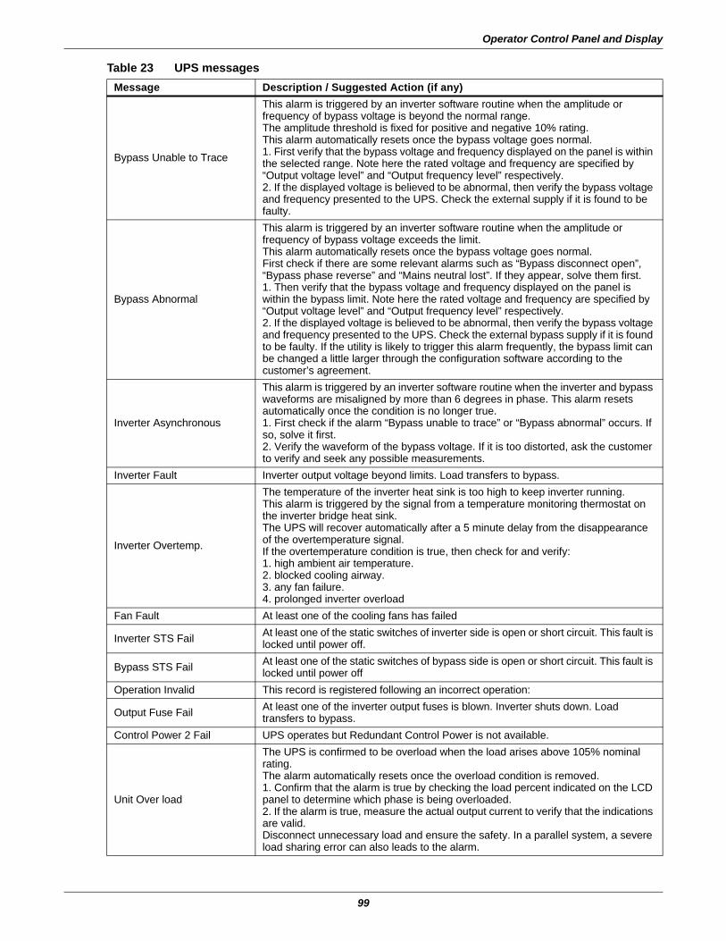
Operator Control Panel and Display
99
Bypass Unable to Trace
This alarm is triggered by an inverter software routine when the amplitude or frequency of bypass voltage is beyond the normal range.The amplitude threshold is fixed for positive and negative 10% rating.This alarm automatically resets once the bypass voltage goes normal.1. First verify that the bypass voltage and frequency displayed on the panel is within the selected range. Note here the rated voltage and frequency are specified by “Output voltage level” and “Output frequency level” respectively.2. If the displayed voltage is believed to be abnormal, then verify the bypass voltage and frequency presented to the UPS. Check the external supply if it is found to be faulty.
Bypass Abnormal
This alarm is triggered by an inverter software routine when the amplitude or frequency of bypass voltage exceeds the limit.This alarm automatically resets once the bypass voltage goes normal.First check if there are some relevant alarms such as “Bypass disconnect open”, “Bypass phase reverse” and “Mains neutral lost”. If they appear, solve them first.1. Then verify that the bypass voltage and frequency displayed on the panel is within the bypass limit. Note here the rated voltage and frequency are specified by “Output voltage level” and “Output frequency level” respectively.2. If the displayed voltage is believed to be abnormal, then verify the bypass voltage and frequency presented to the UPS. Check the external bypass supply if it is found to be faulty. If the utility is likely to trigger this alarm frequently, the bypass limit can be changed a little larger through the configuration software according to the customer’s agreement.
Inverter Asynchronous
This alarm is triggered by an inverter software routine when the inverter and bypass waveforms are misaligned by more than 6 degrees in phase. This alarm resets automatically once the condition is no longer true.1. First check if the alarm “Bypass unable to trace” or “Bypass abnormal” occurs. If so, solve it first.2. Verify the waveform of the bypass voltage. If it is too distorted, ask the customer to verify and seek any possible measurements.
Inverter Fault Inverter output voltage beyond limits. Load transfers to bypass.
Inverter Overtemp.
The temperature of the inverter heat sink is too high to keep inverter running.This alarm is triggered by the signal from a temperature monitoring thermostat on the inverter bridge heat sink.The UPS will recover automatically after a 5 minute delay from the disappearance of the overtemperature signal.If the overtemperature condition is true, then check for and verify:1. high ambient air temperature.2. blocked cooling airway.3. any fan failure.4. prolonged inverter overload
Fan Fault At least one of the cooling fans has failed
Inverter STS Fail At least one of the static switches of inverter side is open or short circuit. This fault is locked until power off.
Bypass STS Fail At least one of the static switches of bypass side is open or short circuit. This fault is locked until power off
Operation Invalid This record is registered following an incorrect operation:
Output Fuse Fail At least one of the inverter output fuses is blown. Inverter shuts down. Load transfers to bypass.
Control Power 2 Fail UPS operates but Redundant Control Power is not available.
Unit Over load
The UPS is confirmed to be overload when the load arises above 105% nominal rating.The alarm automatically resets once the overload condition is removed.1. Confirm that the alarm is true by checking the load percent indicated on the LCD panel to determine which phase is being overloaded.2. If the alarm is true, measure the actual output current to verify that the indications are valid.Disconnect unnecessary load and ensure the safety. In a parallel system, a severe load sharing error can also leads to the alarm.
Table 23 UPS messagesMessage Description / Suggested Action (if any)
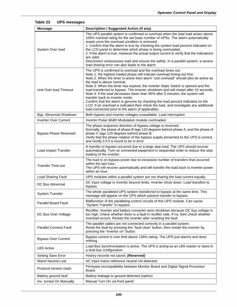
Operator Control Panel and Display
100
System Over load
The UPS parallel system is confirmed to overload when the total load arises above 105% nominal rating for the set basic number of UPSs. The alarm automatically resets once the overload condition is removed.1. Confirm that the alarm is true by checking the system load percent indicated on the LCD panel to determine which phase is being overloaded.2. If the alarm is true, measure the actual output current to verify that the indications are valid.Disconnect unnecessary load and ensure the safety. In a parallel system, a severe load sharing error can also leads to the alarm.
Unit Over load Timeout
The UPS is confirmed to overload and the overload times out.Note 1: the highest loaded phase will indicate overload timing-out first.Note 2: When the timer is active then alarm “unit overload” should also be active as the load is above nominal.Note 3: When the timer has expired, the inverter Static Switch is opened and the load transferred to bypass. The inverter shutdown and will restart after 10 seconds.Note 4: If the load decreases lower than 95% after 5 minutes, the system will transfer back to inverter mode.Confirm that the alarm is genuine by checking the load percent indicated on the LCD. If an overload is indicated then check the load, and investigate any additional load connected prior to the alarm (if applicable).
Byp. Abnormal Shutdown Both bypass and inverter voltages unavailable. Load interruptionInverter Over Current Inverter Pulse Width Modulation module overloaded.
Bypass Phase Reversed
The phase sequence direction of bypass voltage is reversed.Normally, the phase of phase B lags 120 degrees behind phase A, and the phase of phase C lags 120 degrees behind phase B.Verify that the phase rotation of the bypass supply presented to the UPS is correct, and rectify it if it is found to be in error
Load Impact TransferA transfer to bypass occurred due to a large step load. The UPS should recover automatically. Turn on connected equipment in sequential order to reduce the step loading of the inverter.
Transfer Time-outThe load is on bypass power due to excessive number of transfers that occurred within the last hour.The UPS will recover automatically and will transfer the load back to inverter power within an hour.
Load Sharing Fault UPS modules within a parallel system are not sharing the load current equally.
DC Bus Abnormal DC input voltage to inverter beyond limits. Inverter shuts down. Load transfers to bypass.
System Transfer The whole paralleled UPS system transferred to bypass at the same time. This message will appear on the UPS which passive transfer to bypass
Parallel Board Fault Malfunction of the paralleling control circuits of this UPS module. Can cause “System Transfer” to bypass.
DC Bus Over VoltageRectifier, inverter and battery converter were shutdown because DC bus voltage is too high. Check whether there is a fault in rectifier side. If no, then check whether overload occurs. Restart the inverter after resetting the fault
Parallel Connect FaultThe parallel cables are not connected correctly in a parallel system.Reset the fault by pressing the “fault clear” button, then restart the inverter by pressing the “inverter on” button.
Bypass Over Current Bypass current is over limit above 135% rating. The UPS just alarms and does nothing.
LBS Active Load Bus Synchronisation is active. The UPS is acting as an LBS master or slave in a dual bus configuration.
Setting Save Error History records not saved. (Reserved)Mains Neutral Lost AC Input mains reference neutral not detected.
Protocol version clash Firmware incompatibility between Monitor Board and Digital Signal Processor Board.
Battery ground fault Battery leakage to ground detected (option)Inv. turned On Manually Manual Turn On via front panel
Table 23 UPS messagesMessage Description / Suggested Action (if any)
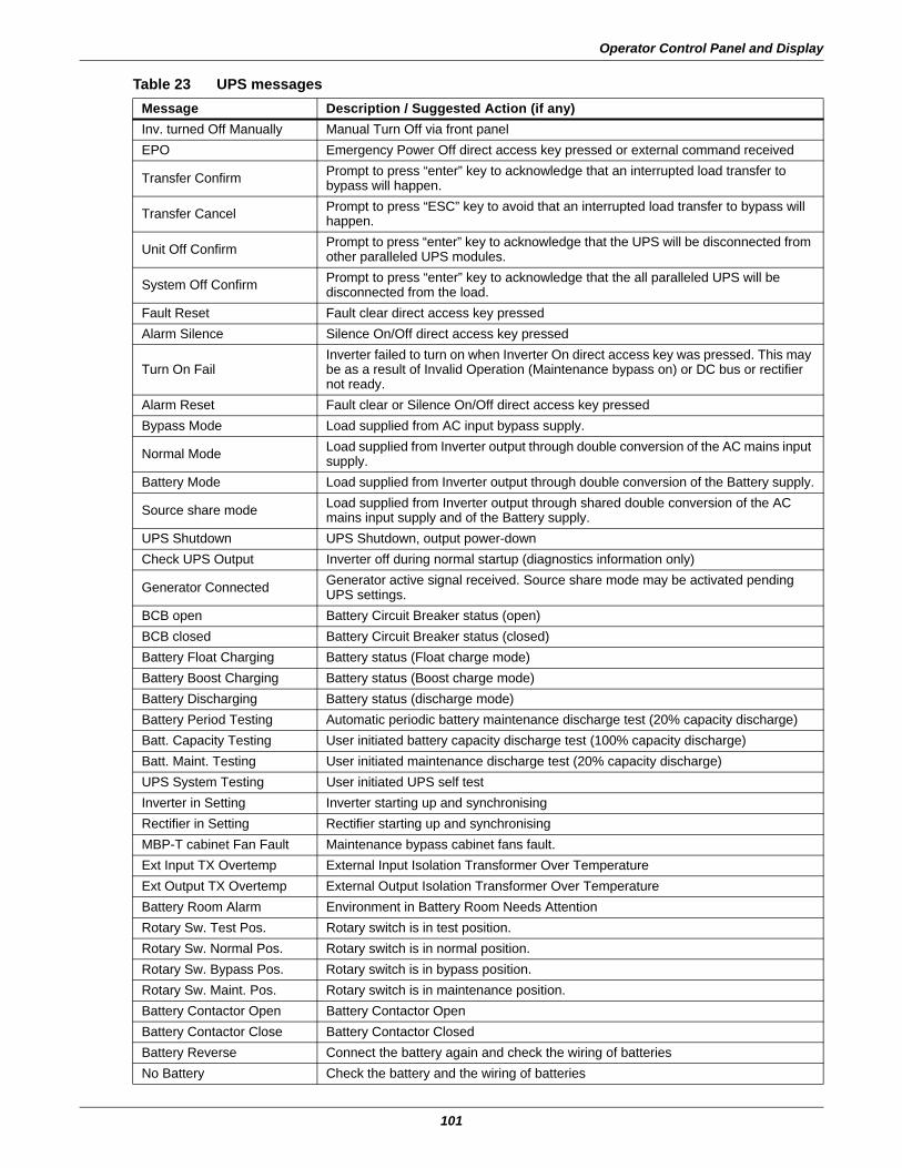
Operator Control Panel and Display
101
Inv. turned Off Manually Manual Turn Off via front panelEPO Emergency Power Off direct access key pressed or external command received
Transfer Confirm Prompt to press “enter” key to acknowledge that an interrupted load transfer to bypass will happen.
Transfer Cancel Prompt to press “ESC” key to avoid that an interrupted load transfer to bypass will happen.
Unit Off Confirm Prompt to press “enter” key to acknowledge that the UPS will be disconnected from other paralleled UPS modules.
System Off Confirm Prompt to press “enter” key to acknowledge that the all paralleled UPS will be disconnected from the load.
Fault Reset Fault clear direct access key pressedAlarm Silence Silence On/Off direct access key pressed
Turn On FailInverter failed to turn on when Inverter On direct access key was pressed. This may be as a result of Invalid Operation (Maintenance bypass on) or DC bus or rectifier not ready.
Alarm Reset Fault clear or Silence On/Off direct access key pressedBypass Mode Load supplied from AC input bypass supply.
Normal Mode Load supplied from Inverter output through double conversion of the AC mains input supply.
Battery Mode Load supplied from Inverter output through double conversion of the Battery supply.
Source share mode Load supplied from Inverter output through shared double conversion of the AC mains input supply and of the Battery supply.
UPS Shutdown UPS Shutdown, output power-downCheck UPS Output Inverter off during normal startup (diagnostics information only)
Generator Connected Generator active signal received. Source share mode may be activated pending UPS settings.
BCB open Battery Circuit Breaker status (open)BCB closed Battery Circuit Breaker status (closed)Battery Float Charging Battery status (Float charge mode)Battery Boost Charging Battery status (Boost charge mode)Battery Discharging Battery status (discharge mode)Battery Period Testing Automatic periodic battery maintenance discharge test (20% capacity discharge)Batt. Capacity Testing User initiated battery capacity discharge test (100% capacity discharge)Batt. Maint. Testing User initiated maintenance discharge test (20% capacity discharge)UPS System Testing User initiated UPS self testInverter in Setting Inverter starting up and synchronisingRectifier in Setting Rectifier starting up and synchronisingMBP-T cabinet Fan Fault Maintenance bypass cabinet fans fault.Ext Input TX Overtemp External Input Isolation Transformer Over TemperatureExt Output TX Overtemp External Output Isolation Transformer Over TemperatureBattery Room Alarm Environment in Battery Room Needs AttentionRotary Sw. Test Pos. Rotary switch is in test position.Rotary Sw. Normal Pos. Rotary switch is in normal position.Rotary Sw. Bypass Pos. Rotary switch is in bypass position.Rotary Sw. Maint. Pos. Rotary switch is in maintenance position.Battery Contactor Open Battery Contactor OpenBattery Contactor Close Battery Contactor ClosedBattery Reverse Connect the battery again and check the wiring of batteriesNo Battery Check the battery and the wiring of batteries
Table 23 UPS messagesMessage Description / Suggested Action (if any)
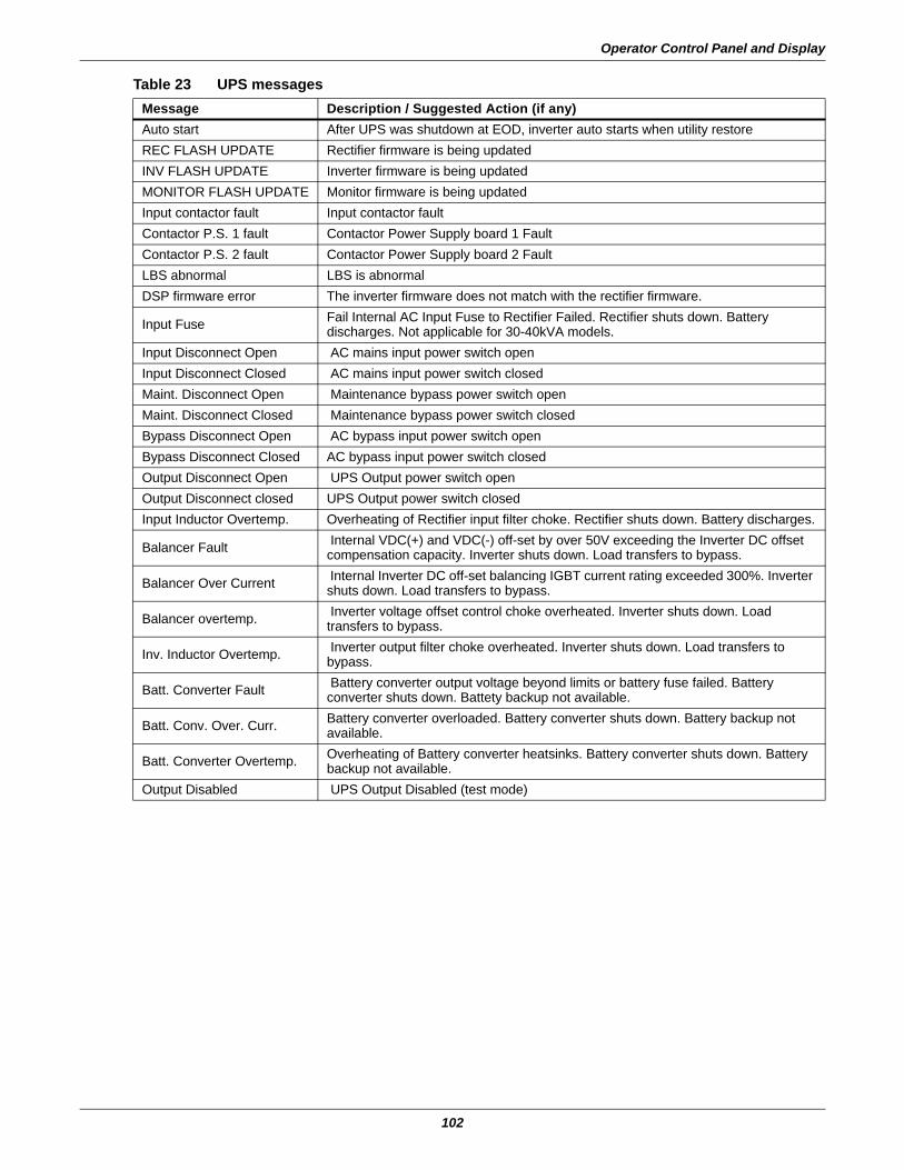
Operator Control Panel and Display
102
Auto start After UPS was shutdown at EOD, inverter auto starts when utility restoreREC FLASH UPDATE Rectifier firmware is being updatedINV FLASH UPDATE Inverter firmware is being updatedMONITOR FLASH UPDATE Monitor firmware is being updatedInput contactor fault Input contactor faultContactor P.S. 1 fault Contactor Power Supply board 1 FaultContactor P.S. 2 fault Contactor Power Supply board 2 FaultLBS abnormal LBS is abnormalDSP firmware error The inverter firmware does not match with the rectifier firmware.
Input Fuse Fail Internal AC Input Fuse to Rectifier Failed. Rectifier shuts down. Battery discharges. Not applicable for 30-40kVA models.
Input Disconnect Open AC mains input power switch openInput Disconnect Closed AC mains input power switch closedMaint. Disconnect Open Maintenance bypass power switch openMaint. Disconnect Closed Maintenance bypass power switch closedBypass Disconnect Open AC bypass input power switch openBypass Disconnect Closed AC bypass input power switch closedOutput Disconnect Open UPS Output power switch openOutput Disconnect closed UPS Output power switch closedInput Inductor Overtemp. Overheating of Rectifier input filter choke. Rectifier shuts down. Battery discharges.
Balancer Fault Internal VDC(+) and VDC(-) off-set by over 50V exceeding the Inverter DC offset compensation capacity. Inverter shuts down. Load transfers to bypass.
Balancer Over Current Internal Inverter DC off-set balancing IGBT current rating exceeded 300%. Inverter shuts down. Load transfers to bypass.
Balancer overtemp. Inverter voltage offset control choke overheated. Inverter shuts down. Load transfers to bypass.
Inv. Inductor Overtemp. Inverter output filter choke overheated. Inverter shuts down. Load transfers to bypass.
Batt. Converter Fault Battery converter output voltage beyond limits or battery fuse failed. Battery converter shuts down. Battety backup not available.
Batt. Conv. Over. Curr. Battery converter overloaded. Battery converter shuts down. Battery backup not available.
Batt. Converter Overtemp. Overheating of Battery converter heatsinks. Battery converter shuts down. Battery backup not available.
Output Disabled UPS Output Disabled (test mode)
Table 23 UPS messagesMessage Description / Suggested Action (if any)
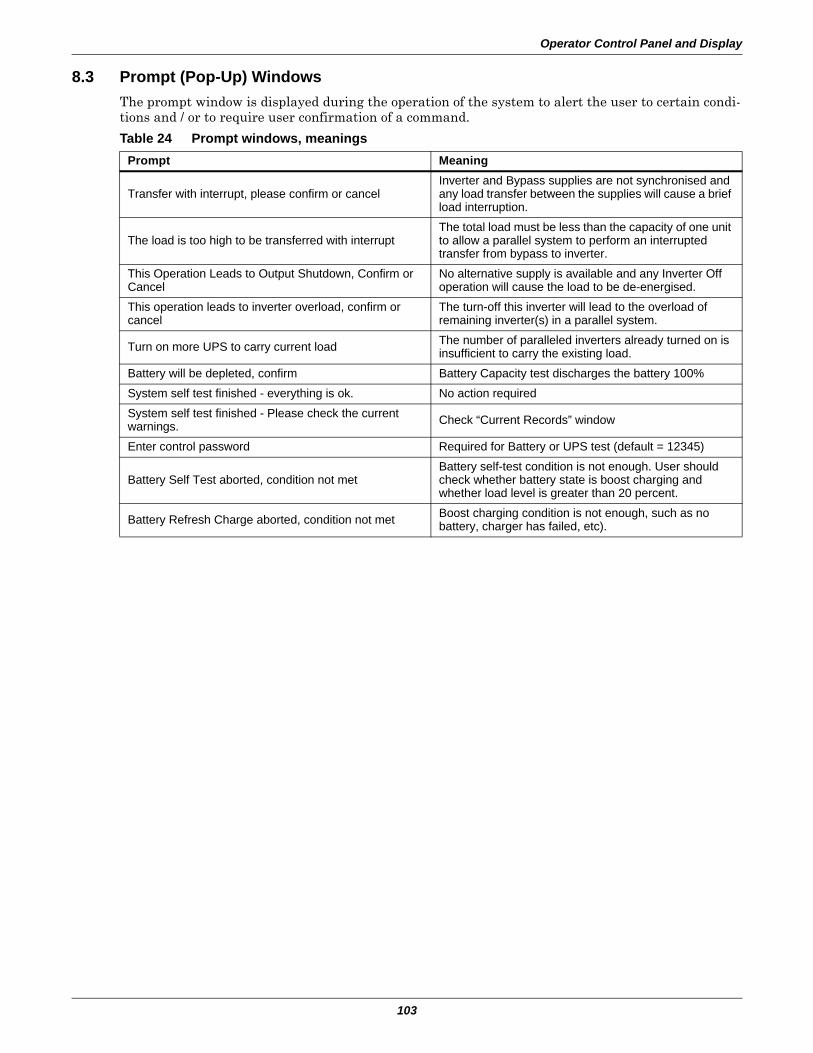
Operator Control Panel and Display
103
8.3 Prompt (Pop-Up) WindowsThe prompt window is displayed during the operation of the system to alert the user to certain condi-tions and / or to require user confirmation of a command.
Table 24 Prompt windows, meaningsPrompt Meaning
Transfer with interrupt, please confirm or cancelInverter and Bypass supplies are not synchronised and any load transfer between the supplies will cause a brief load interruption.
The load is too high to be transferred with interruptThe total load must be less than the capacity of one unit to allow a parallel system to perform an interrupted transfer from bypass to inverter.
This Operation Leads to Output Shutdown, Confirm or Cancel
No alternative supply is available and any Inverter Off operation will cause the load to be de-energised.
This operation leads to inverter overload, confirm or cancel
The turn-off this inverter will lead to the overload of remaining inverter(s) in a parallel system.
Turn on more UPS to carry current load The number of paralleled inverters already turned on is insufficient to carry the existing load.
Battery will be depleted, confirm Battery Capacity test discharges the battery 100%System self test finished - everything is ok. No action requiredSystem self test finished - Please check the current warnings. Check “Current Records” window
Enter control password Required for Battery or UPS test (default = 12345)
Battery Self Test aborted, condition not metBattery self-test condition is not enough. User should check whether battery state is boost charging and whether load level is greater than 20 percent.
Battery Refresh Charge aborted, condition not met Boost charging condition is not enough, such as no battery, charger has failed, etc).
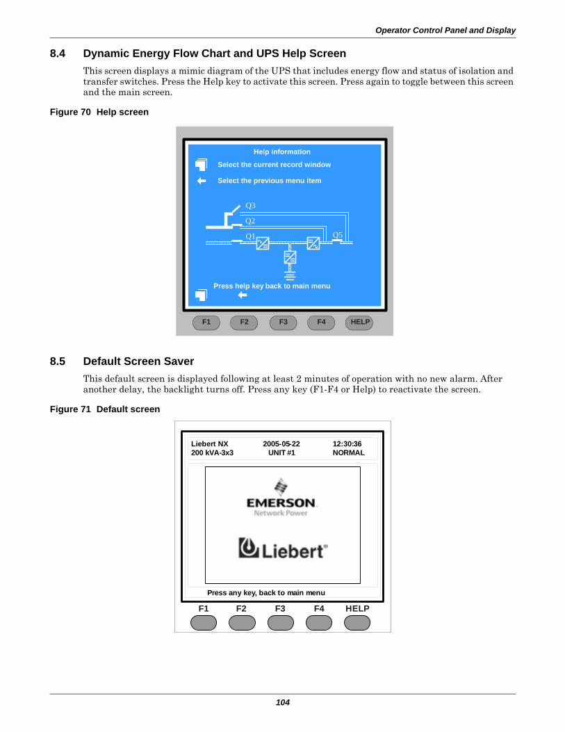
Operator Control Panel and Display
104
8.4 Dynamic Energy Flow Chart and UPS Help ScreenThis screen displays a mimic diagram of the UPS that includes energy flow and status of isolation and transfer switches. Press the Help key to activate this screen. Press again to toggle between this screen and the main screen.
Figure 70 Help screen
8.5 Default Screen SaverThis default screen is displayed following at least 2 minutes of operation with no new alarm. After another delay, the backlight turns off. Press any key (F1-F4 or Help) to reactivate the screen.
Figure 71 Default screen
F2 F4 HELPF1 F3
Help information
Select the previous menu item
Select the current record window
Q3
Q2
Q1 Q5
Press help key back to main menu
F2 F3 F4 HELPF1
Liebert NX 2005-05-22 12:30:36200 kVA-3x3 UNIT #1 NORMAL
Press any key, back to main menu
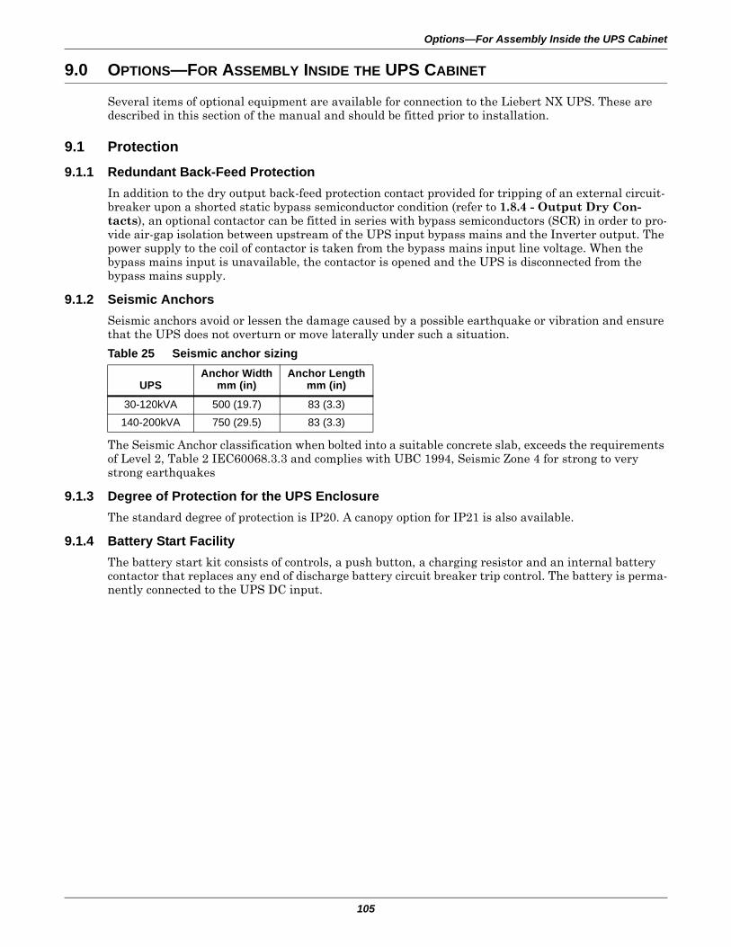
Options—For Assembly Inside the UPS Cabinet
105
9.0 OPTIONS—FOR ASSEMBLY INSIDE THE UPS CABINET
Several items of optional equipment are available for connection to the Liebert NX UPS. These are described in this section of the manual and should be fitted prior to installation.
9.1 Protection
9.1.1 Redundant Back-Feed Protection In addition to the dry output back-feed protection contact provided for tripping of an external circuit-breaker upon a shorted static bypass semiconductor condition (refer to 1.8.4 - Output Dry Con-tacts), an optional contactor can be fitted in series with bypass semiconductors (SCR) in order to pro-vide air-gap isolation between upstream of the UPS input bypass mains and the Inverter output. The power supply to the coil of contactor is taken from the bypass mains input line voltage. When the bypass mains input is unavailable, the contactor is opened and the UPS is disconnected from the bypass mains supply.
9.1.2 Seismic AnchorsSeismic anchors avoid or lessen the damage caused by a possible earthquake or vibration and ensure that the UPS does not overturn or move laterally under such a situation.
The Seismic Anchor classification when bolted into a suitable concrete slab, exceeds the requirements of Level 2, Table 2 IEC60068.3.3 and complies with UBC 1994, Seismic Zone 4 for strong to very strong earthquakes
9.1.3 Degree of Protection for the UPS EnclosureThe standard degree of protection is IP20. A canopy option for IP21 is also available.
9.1.4 Battery Start FacilityThe battery start kit consists of controls, a push button, a charging resistor and an internal battery contactor that replaces any end of discharge battery circuit breaker trip control. The battery is perma-nently connected to the UPS DC input.
Table 25 Seismic anchor sizing
UPSAnchor Width
mm (in)Anchor Length
mm (in)
30-120kVA 500 (19.7) 83 (3.3)140-200kVA 750 (29.5) 83 (3.3)
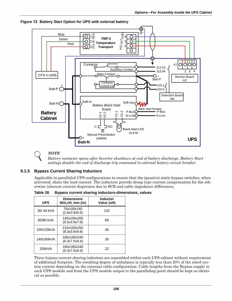
Options—For Assembly Inside the UPS Cabinet
106
Figure 72 Battery Start Option for UPS with external battery
9.1.5 Bypass Current Sharing InductorsApplicable in paralleled UPS configurations to ensure that the (passive) static bypass switches, when activated, share the load current. The inductors provide droop type current compensation for the oth-erwise inherent current dispersion due to SCR and cable impedance differences.
Three bypass current sharing inductors are assembled within each UPS cabinet without requirement of additional footprint. The resulting degree of unbalance is typically less than 20% of the rated sys-tem current depending on the external cable configuration. Cable lengths from the Bypass supply to each UPS module and from the UPS module output to the paralleling point should be kept as identi-cal as possible.
NOTEBattery contactor opens after Inverter shutdown at end of battery discharge. Battery Start settings disable the end of discharge trip command to external battery circuit breaker.
Table 26 Bypass current sharing inductors-dimensions, values
UPSDimensions
WxLxH, mm (in)Inductor
Value (uH)
30/ 40 kVA 70x100x140(2.8x3.9x5.5) 122
60/80 kVA 140x100x200(5.5x3.9x7.9) 65
100/120kVA 210x100x250(8.3x3.9x9.8) 40
140/160kVA 160x190x240(6.3x7.5x9.4) 26
200kVA 160x190x240(6.3x7.5x9.4) 22
Black-Start Resistor
Black-Start LEDAL6-M
Auxiliary ContactMain Contact
Contactor Control Coil
Battery Black-Start Board
Contactor
Soft-In Soft-OutX
2-1
X2-
2
X1-
1
X1-
2 P-BusN-Line
NNO
PC
J15-2J15-1
Batt-P
J12-33
+
J12-34
X7
2 3 4
Monitor Board-U2
Detection Board-M4
UPS
P-BusN-Line
Manual Press-Button(AB6M)
Batt-N+
Battery Cabinet
Batt-N-
Batt-P+
OT6-4 LM35
BlueGreen
Red
123
GND
INP
12
TMP-2Temperature
Transport
OU
TP1
2G
ND
32
4
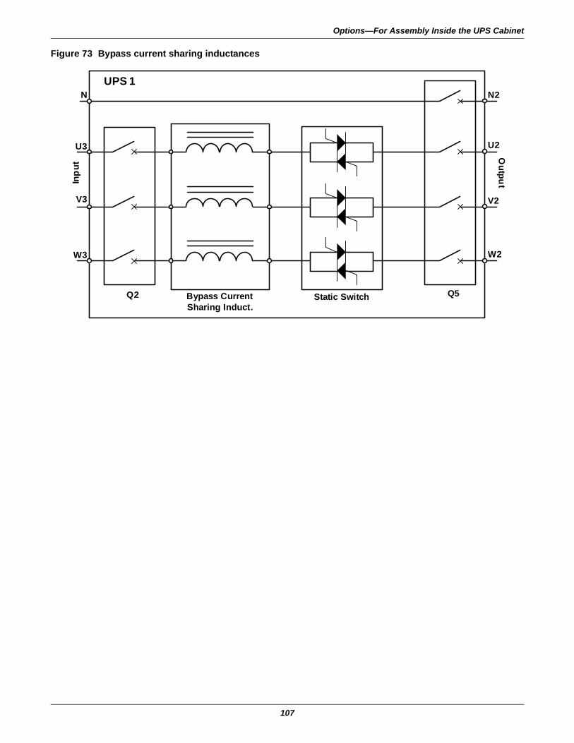
Options—For Assembly Inside the UPS Cabinet
107
Figure 73 Bypass current sharing inductances
UPS 1In
put
Outpu
t
Static SwitchBypass CurrentSharing Induct.
N
U3
V3
W3
Q2 Q5
N2
U2
V2
W2
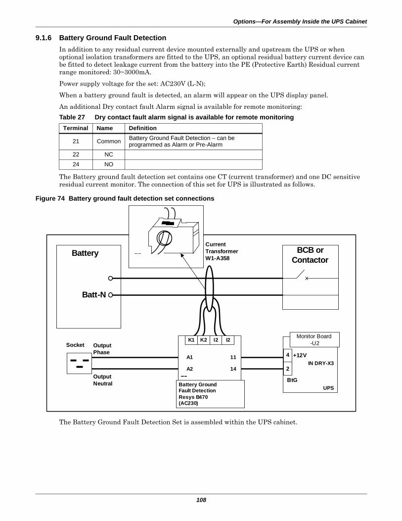
Options—For Assembly Inside the UPS Cabinet
108
9.1.6 Battery Ground Fault DetectionIn addition to any residual current device mounted externally and upstream the UPS or when optional isolation transformers are fitted to the UPS, an optional residual battery current device can be fitted to detect leakage current from the battery into the PE (Protective Earth) Residual current range monitored: 30~3000mA.
Power supply voltage for the set: AC230V (L-N);
When a battery ground fault is detected, an alarm will appear on the UPS display panel.
An additional Dry contact fault Alarm signal is available for remote monitoring:
The Battery ground fault detection set contains one CT (current transformer) and one DC sensitive residual current monitor. The connection of this set for UPS is illustrated as follows.
Figure 74 Battery ground fault detection set connections
The Battery Ground Fault Detection Set is assembled within the UPS cabinet.
Table 27 Dry contact fault alarm signal is available for remote monitoringTerminal Name Definition
21 Common Battery Ground Fault Detection – can be programmed as Alarm or Pre-Alarm
22 NC24 NO
BCB or Contactor
Battery
Batt-N
Socket OutputPhase
OutputNeutral
Current TransformerW1-A358
X
Monitor Board-U2
UPS
IN DRY-X3+12V
BtGBattery GroundFault DetectionResys B470(AC230)
11
14
A1
A2
K1 K2 I2 I2
4
2
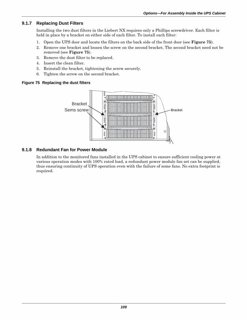
Options—For Assembly Inside the UPS Cabinet
109
9.1.7 Replacing Dust FiltersInstalling the two dust filters in the Liebert NX requires only a Phillips screwdriver. Each filter is held in place by a bracket on either side of each filter. To install each filter:
1. Open the UPS door and locate the filters on the back side of the front door (see Figure 75).2. Remove one bracket and loosen the screw on the second bracket. The second bracket need not be
removed (see Figure 75).3. Remove the dust filter to be replaced.4. Insert the clean filter.5. Reinstall the bracket, tightening the screw securely.6. Tighten the screw on the second bracket.
Figure 75 Replacing the dust filters
9.1.8 Redundant Fan for Power ModuleIn addition to the monitored fans installed in the UPS cabinet to ensure sufficient cooling power at various operation modes with 100% rated load, a redundant power module fan set can be supplied, thus ensuring continuity of UPS operation even with the failure of some fans. No extra footprint is required.
BracketSems screwBracket
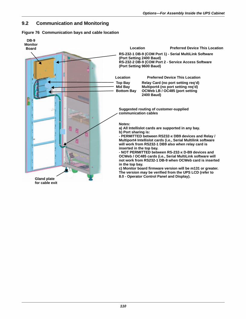
Options—For Assembly Inside the UPS Cabinet
110
9.2 Communication and Monitoring
Figure 76 Communication bays and cable location
(
=
Notes:a) All Intellislot cards are supported in any bay.b) Port sharing is:- PERMITTED between RS232-x DB9 devices and Relay / Multiport4 Intellislot cards (i.e., Serial Multilink software will work from RS232-1 DB9 also when relay card is inserted in the top bay.- NOT PERMITTED between RS-232-x D-B9 devices and OCWeb / OC485 cards (i.e., Serial MultiLink software will not work from RS232-1 DB-9 when OCWeb card is inserted in the top bay.c) Monitor board firmware version will be m131 or greater. The version may be verified from the UPS LCD (refer to 8.0 - Operator Control Panel and Display).
RS-232-1 DB-9 (COM Port 1) - Serial MultiLink Software(Port Setting 2400 Baud)RS-232-2 DB-9 (COM Port 2 - Service Access Software(Port Setting 9600 Baud)
Top BayMid BayBottom Bay
Relay Card (no port setting req’d)Multiport4 (no port setting req’d)OCWeb LB / OC485 (port setting2400 Baud)
Suggested routing of customer-supplied communication cables
Gland platefor cable exit
Preferred Device This LocationLocation
Preferred Device This LocationLocation
DB-9Monitor Board
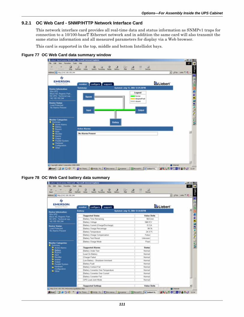
Options—For Assembly Inside the UPS Cabinet
111
9.2.1 OC Web Card - SNMP/HTTP Network Interface CardThis network interface card provides all real-time data and status information as SNMPv1 traps for connection to a 10/100-baseT Ethernet network and in addition the same card will also transmit the same status information and all measured parameters for display via a Web browser.
This card is supported in the top, middle and bottom Intellislot bays.
Figure 77 OC Web Card data summary window
Figure 78 OC Web Card battery data summary
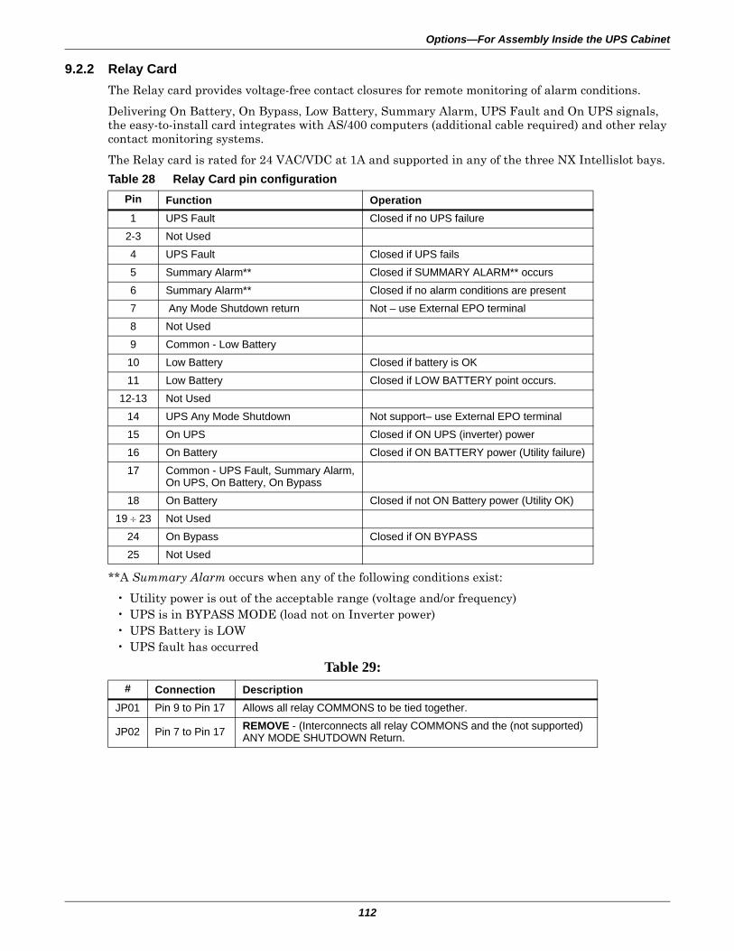
Options—For Assembly Inside the UPS Cabinet
112
9.2.2 Relay CardThe Relay card provides voltage-free contact closures for remote monitoring of alarm conditions.
Delivering On Battery, On Bypass, Low Battery, Summary Alarm, UPS Fault and On UPS signals, the easy-to-install card integrates with AS/400 computers (additional cable required) and other relay contact monitoring systems.
The Relay card is rated for 24 VAC/VDC at 1A and supported in any of the three NX Intellislot bays.
**A Summary Alarm occurs when any of the following conditions exist:
• Utility power is out of the acceptable range (voltage and/or frequency)• UPS is in BYPASS MODE (load not on Inverter power)• UPS Battery is LOW• UPS fault has occurred
Table 28 Relay Card pin configurationPin Function Operation1 UPS Fault Closed if no UPS failure
2-3 Not Used4 UPS Fault Closed if UPS fails5 Summary Alarm** Closed if SUMMARY ALARM** occurs6 Summary Alarm** Closed if no alarm conditions are present7 Any Mode Shutdown return Not – use External EPO terminal8 Not Used9 Common - Low Battery10 Low Battery Closed if battery is OK11 Low Battery Closed if LOW BATTERY point occurs.
12-13 Not Used14 UPS Any Mode Shutdown Not support– use External EPO terminal15 On UPS Closed if ON UPS (inverter) power16 On Battery Closed if ON BATTERY power (Utility failure)17 Common - UPS Fault, Summary Alarm,
On UPS, On Battery, On Bypass18 On Battery Closed if not ON Battery power (Utility OK)
19 ÷ 23 Not Used24 On Bypass Closed if ON BYPASS25 Not Used
Table 29: # Connection Description
JP01 Pin 9 to Pin 17 Allows all relay COMMONS to be tied together.
JP02 Pin 7 to Pin 17 REMOVE - (Interconnects all relay COMMONS and the (not supported) ANY MODE SHUTDOWN Return.
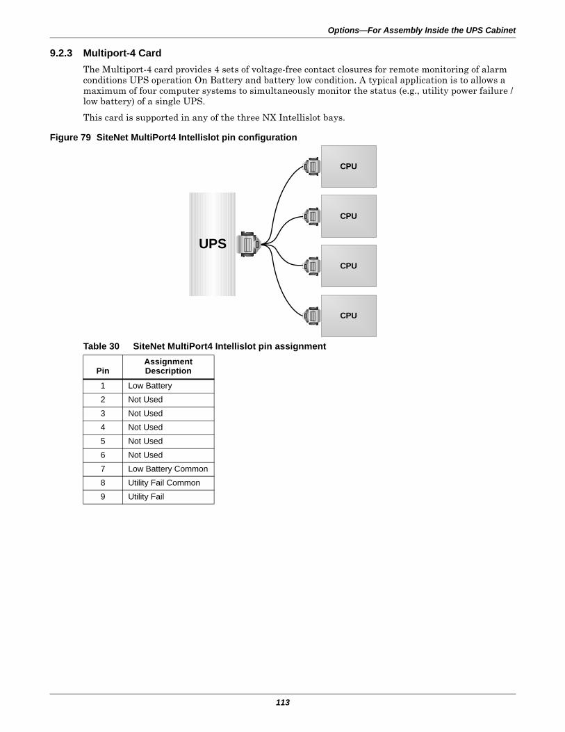
Options—For Assembly Inside the UPS Cabinet
113
9.2.3 Multiport-4 CardThe Multiport-4 card provides 4 sets of voltage-free contact closures for remote monitoring of alarm conditions UPS operation On Battery and battery low condition. A typical application is to allows a maximum of four computer systems to simultaneously monitor the status (e.g., utility power failure / low battery) of a single UPS.
This card is supported in any of the three NX Intellislot bays.
Figure 79 SiteNet MultiPort4 Intellislot pin configuration
Table 30 SiteNet MultiPort4 Intellislot pin assignment
PinAssignmentDescription
1 Low Battery2 Not Used3 Not Used4 Not Used5 Not Used
6 Not Used7 Low Battery Common8 Utility Fail Common9 Utility Fail
UPS
CPU
CPU
CPU
CPU
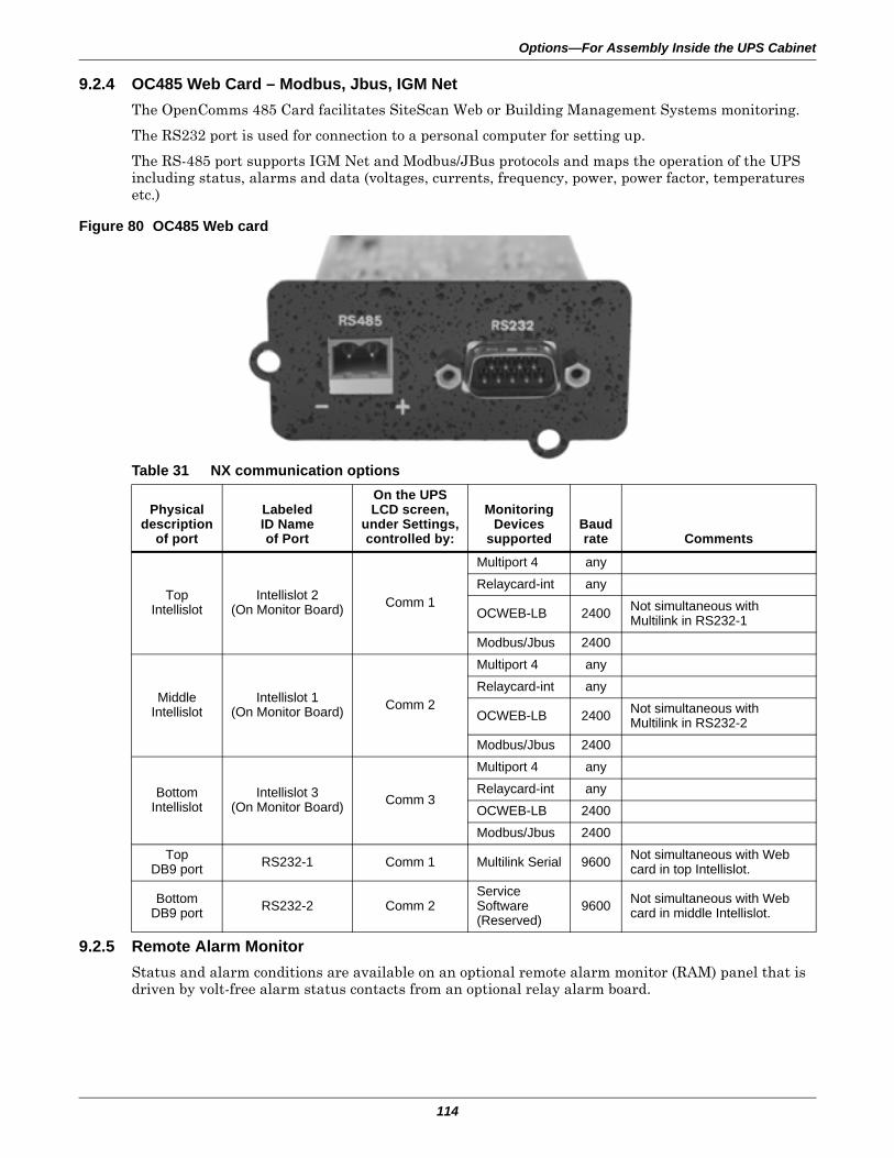
Options—For Assembly Inside the UPS Cabinet
114
9.2.4 OC485 Web Card – Modbus, Jbus, IGM NetThe OpenComms 485 Card facilitates SiteScan Web or Building Management Systems monitoring.
The RS232 port is used for connection to a personal computer for setting up.
The RS-485 port supports IGM Net and Modbus/JBus protocols and maps the operation of the UPS including status, alarms and data (voltages, currents, frequency, power, power factor, temperatures etc.)
Figure 80 OC485 Web card
9.2.5 Remote Alarm MonitorStatus and alarm conditions are available on an optional remote alarm monitor (RAM) panel that is driven by volt-free alarm status contacts from an optional relay alarm board.
Table 31 NX communication options
Physicaldescription
of port
LabeledID Nameof Port
On the UPSLCD screen,
under Settings,controlled by:
MonitoringDevices
supportedBaudrate Comments
TopIntellislot
Intellislot 2(On Monitor Board) Comm 1
Multiport 4 anyRelaycard-int any
OCWEB-LB 2400 Not simultaneous with Multilink in RS232-1
Modbus/Jbus 2400
MiddleIntellislot
Intellislot 1(On Monitor Board) Comm 2
Multiport 4 anyRelaycard-int any
OCWEB-LB 2400 Not simultaneous with Multilink in RS232-2
Modbus/Jbus 2400
BottomIntellislot
Intellislot 3(On Monitor Board) Comm 3
Multiport 4 anyRelaycard-int anyOCWEB-LB 2400Modbus/Jbus 2400
TopDB9 port RS232-1 Comm 1 Multilink Serial 9600 Not simultaneous with Web
card in top Intellislot.
BottomDB9 port RS232-2 Comm 2
Service Software(Reserved)
9600 Not simultaneous with Web card in middle Intellislot.
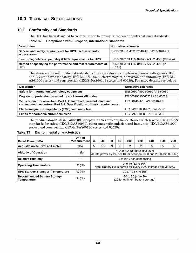
Technical Specifications
115
10.0 TECHNICAL SPECIFICATIONS
10.1 Conformity and StandardsThe UPS has been designed to conform to the following European and international standards:
The above mentioned product standards incorporate relevant compliance clauses with generic IEC and EN standards for safety (IEC/EN/AS60950), electromagnetic emission and immunity (IEC/EN/AS61000 series) and construction (IEC/EN/AS60146 series and 60529). For more details, see below:
The product standards in Table 32 incorporate relevant compliance clauses with generic IEC and EN standards for safety (IEC/EN/AS60950), electromagnetic emission and immunity (IEC/EN/AS61000 series) and construction (IEC/EN/AS60146 series and 60529).
Table 32 Compliance with European, international standardsDescription Normative referenceGeneral and safety requirements for UPS used in operator access areas
EN 50091-1-1 /IEC 62040-1-1 / AS 62040-1-1
Electromagnetic compatibility (EMC) requirements for UPS EN 50091-2 / IEC 62040-2 / AS 62040-2 (Class A)Method of specifying the performance and test requirements of UPS
EN 50091-3 / IEC 62040-3 / AS 62040-3 (VFI SS 111)
Description Normative referenceSafety for Information technology equipment EN60950 / IEC 60950 / AS 60950 Degrees of protection provided by enclosures (IP code). EN 60529/ IEC60529 / AS 60529Semiconductor convertors. Part 1: General requirements and line commutated convertors. Part 1-1: Specifications of basic requirements
IEC 60146-1-1 / AS 60146-1-1
Electromagnetic compatibility (EMC): immunity test IEC / AS 61000-4-2, -3-4, -5, -6Limits for harmonic current emission IEC / AS 61000-3-2, -3-4, -3-6
Table 33 Environmental characteristics
Rated Power, kVAUnit of
Measurement 30 40 60 80 100 120 140 160 200
Acoustic noise level at 1 meter dBA 55 55 59 59 62 62 65 65 66
Altitude of Operation m (ft) ≤1000 (3280) above sea levelderate power by 1% per 100m between 1000 and 2000 (3280-6562)
Relative Humidity — 0 to 95% non condensing
Operating Temperature °C (°F) 0 to 40 (32 to 104)Note: Battery life is halved for every 10°C increase above 20°C
UPS Storage-Transport Temperature °C (°F) -20 to 70 (-4 to 158)Recommended Battery StorageTemperature °C (°F) -20 to 30 (-4 to 86)
(20 for optimum battery storage)
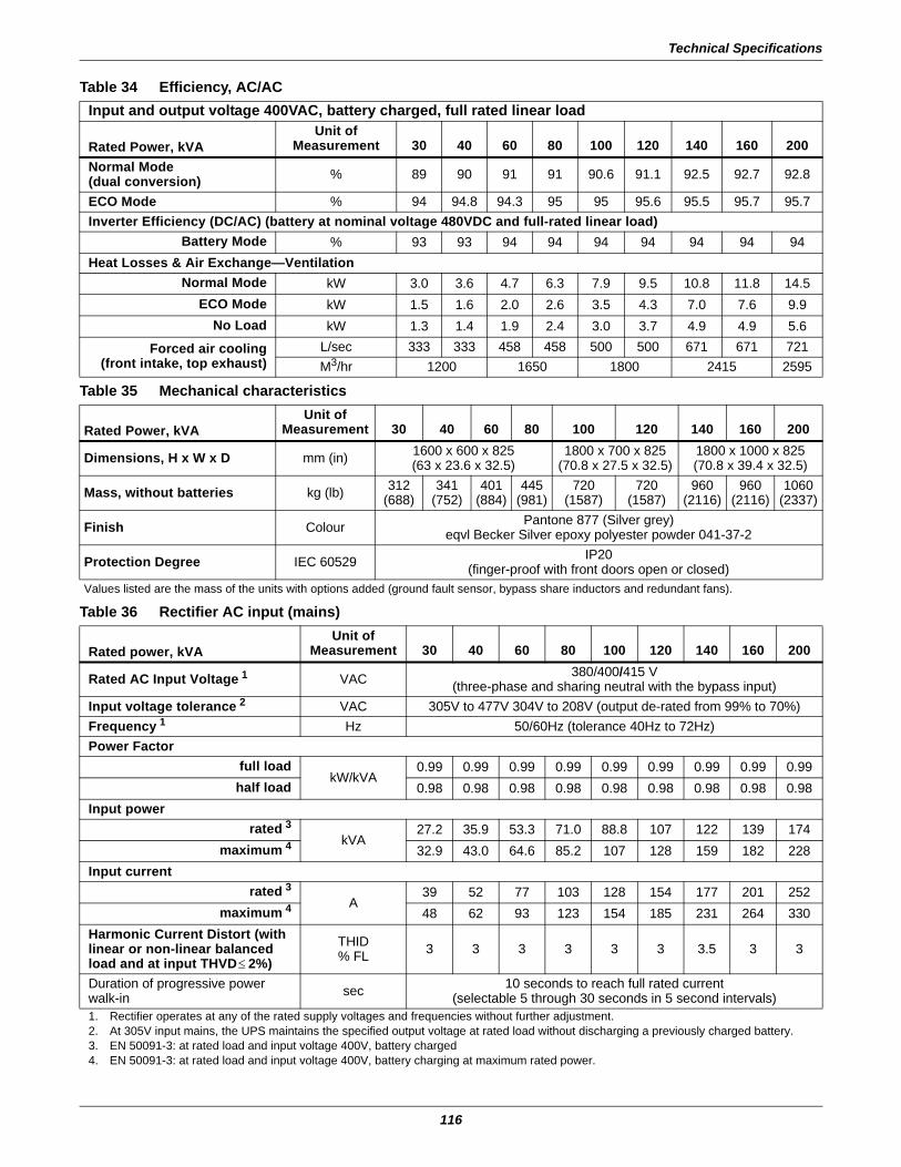
Technical Specifications
116
Table 34 Efficiency, AC/ACInput and output voltage 400VAC, battery charged, full rated linear load
Rated Power, kVAUnit of
Measurement 30 40 60 80 100 120 140 160 200Normal Mode(dual conversion) % 89 90 91 91 90.6 91.1 92.5 92.7 92.8
ECO Mode % 94 94.8 94.3 95 95 95.6 95.5 95.7 95.7Inverter Efficiency (DC/AC) (battery at nominal voltage 480VDC and full-rated linear load)
Battery Mode % 93 93 94 94 94 94 94 94 94Heat Losses & Air Exchange—Ventilation
Normal Mode kW 3.0 3.6 4.7 6.3 7.9 9.5 10.8 11.8 14.5ECO Mode kW 1.5 1.6 2.0 2.6 3.5 4.3 7.0 7.6 9.9
No Load kW 1.3 1.4 1.9 2.4 3.0 3.7 4.9 4.9 5.6
Forced air cooling(front intake, top exhaust)
L/sec 333 333 458 458 500 500 671 671 721M3/hr 1200 1650 1800 2415 2595
Table 35 Mechanical characteristics
Rated Power, kVAUnit of
Measurement 30 40 60 80 100 120 140 160 200
Dimensions, H x W x D mm (in) 1600 x 600 x 825(63 x 23.6 x 32.5)
1800 x 700 x 825(70.8 x 27.5 x 32.5)
1800 x 1000 x 825(70.8 x 39.4 x 32.5)
Mass, without batteries kg (lb) 312(688)
341(752)
401(884)
445(981)
720(1587)
720(1587)
960(2116)
960(2116)
1060(2337)
Finish Colour Pantone 877 (Silver grey) eqvl Becker Silver epoxy polyester powder 041-37-2
Protection Degree IEC 60529 IP20(finger-proof with front doors open or closed)
Values listed are the mass of the units with options added (ground fault sensor, bypass share inductors and redundant fans).
Table 36 Rectifier AC input (mains)
Rated power, kVAUnit of
Measurement 30 40 60 80 100 120 140 160 200
Rated AC Input Voltage 1 VAC 380/400/415 V(three-phase and sharing neutral with the bypass input)
Input voltage tolerance 2 VAC 305V to 477V 304V to 208V (output de-rated from 99% to 70%)Frequency 1 Hz 50/60Hz (tolerance 40Hz to 72Hz)Power Factor
full loadkW/kVA
0.99 0.99 0.99 0.99 0.99 0.99 0.99 0.99 0.99half load 0.98 0.98 0.98 0.98 0.98 0.98 0.98 0.98 0.98
Input powerrated 3
kVA27.2 35.9 53.3 71.0 88.8 107 122 139 174
maximum 4 32.9 43.0 64.6 85.2 107 128 159 182 228Input current
rated 3A
39 52 77 103 128 154 177 201 252maximum 4 48 62 93 123 154 185 231 264 330
Harmonic Current Distort (with linear or non-linear balanced load and at input THVD≤ 2%)
THID% FL 3 3 3 3 3 3 3.5 3 3
Duration of progressive power walk-in sec 10 seconds to reach full rated current
(selectable 5 through 30 seconds in 5 second intervals)1. Rectifier operates at any of the rated supply voltages and frequencies without further adjustment.2. At 305V input mains, the UPS maintains the specified output voltage at rated load without discharging a previously charged battery.3. EN 50091-3: at rated load and input voltage 400V, battery charged4. EN 50091-3: at rated load and input voltage 400V, battery charging at maximum rated power.
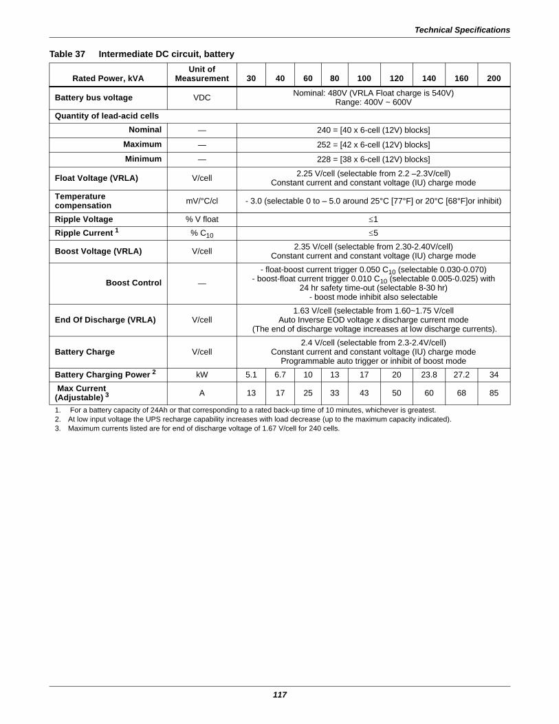
Technical Specifications
117
Table 37 Intermediate DC circuit, battery
Rated Power, kVAUnit of
Measurement 30 40 60 80 100 120 140 160 200
Battery bus voltage VDC Nominal: 480V (VRLA Float charge is 540V)Range: 400V ~ 600V
Quantity of lead-acid cellsNominal — 240 = [40 x 6-cell (12V) blocks]
Maximum — 252 = [42 x 6-cell (12V) blocks]
Minimum — 228 = [38 x 6-cell (12V) blocks]
Float Voltage (VRLA) V/cell 2.25 V/cell (selectable from 2.2 –2.3V/cell)Constant current and constant voltage (IU) charge mode
Temperature compensation mV/°C/cl - 3.0 (selectable 0 to – 5.0 around 25°C [77°F] or 20°C [68°F]or inhibit)
Ripple Voltage % V float ≤1Ripple Current 1 % C10 ≤5
Boost Voltage (VRLA) V/cell 2.35 V/cell (selectable from 2.30-2.40V/cell)Constant current and constant voltage (IU) charge mode
Boost Control —- float-boost current trigger 0.050 C10 (selectable 0.030-0.070)
- boost-float current trigger 0.010 C10 (selectable 0.005-0.025) with24 hr safety time-out (selectable 8-30 hr)
- boost mode inhibit also selectable
End Of Discharge (VRLA) V/cell1.63 V/cell (selectable from 1.60~1.75 V/cell
Auto Inverse EOD voltage x discharge current mode (The end of discharge voltage increases at low discharge currents).
Battery Charge V/cell2.4 V/cell (selectable from 2.3-2.4V/cell)
Constant current and constant voltage (IU) charge modeProgrammable auto trigger or inhibit of boost mode
Battery Charging Power 2 kW 5.1 6.7 10 13 17 20 23.8 27.2 34 Max Current (Adjustable) 3 A 13 17 25 33 43 50 60 68 85
1. For a battery capacity of 24Ah or that corresponding to a rated back-up time of 10 minutes, whichever is greatest.2. At low input voltage the UPS recharge capability increases with load decrease (up to the maximum capacity indicated).3. Maximum currents listed are for end of discharge voltage of 1.67 V/cell for 240 cells.
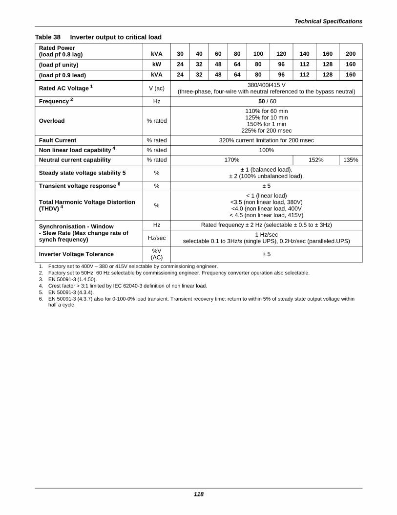
Technical Specifications
118
Table 38 Inverter output to critical loadRated Power(load pf 0.8 lag) kVA 30 40 60 80 100 120 140 160 200
(load pf unity) kW 24 32 48 64 80 96 112 128 160
(load pf 0.9 lead) kVA 24 32 48 64 80 96 112 128 160
Rated AC Voltage 1 V (ac) 380/400/415 V(three-phase, four-wire with neutral referenced to the bypass neutral)
Frequency 2 Hz 50 / 60
Overload % rated110% for 60 min125% for 10 min150% for 1 min
225% for 200 msecFault Current % rated 320% current limitation for 200 msecNon linear load capability 4 % rated 100%Neutral current capability % rated 170% 152% 135%
Steady state voltage stability 5 % ± 1 (balanced load), ± 2 (100% unbalanced load),
Transient voltage response 6 % ± 5
Total Harmonic Voltage Distortion (THDV) 4 %
< 1 (linear load)<3.5 (non linear load, 380V)<4.0 (non linear load, 400V
< 4.5 (non linear load, 415V)
Synchronisation - Window- Slew Rate (Max change rate of synch frequency)
Hz Rated frequency ± 2 Hz (selectable ± 0.5 to ± 3Hz)
Hz/sec 1 Hz/sec selectable 0.1 to 3Hz/s (single UPS), 0.2Hz/sec (paralleled.UPS)
Inverter Voltage Tolerance %V (AC) ± 5
1. Factory set to 400V – 380 or 415V selectable by commissioning engineer.2. Factory set to 50Hz; 60 Hz selectable by commissioning engineer. Frequency converter operation also selectable.3. EN 50091-3 (1.4.50).4. Crest factor > 3:1 limited by IEC 62040-3 definition of non linear load. 5. EN 50091-3 (4.3.4).6. EN 50091-3 (4.3.7) also for 0-100-0% load transient. Transient recovery time: return to within 5% of steady state output voltage within
half a cycle.
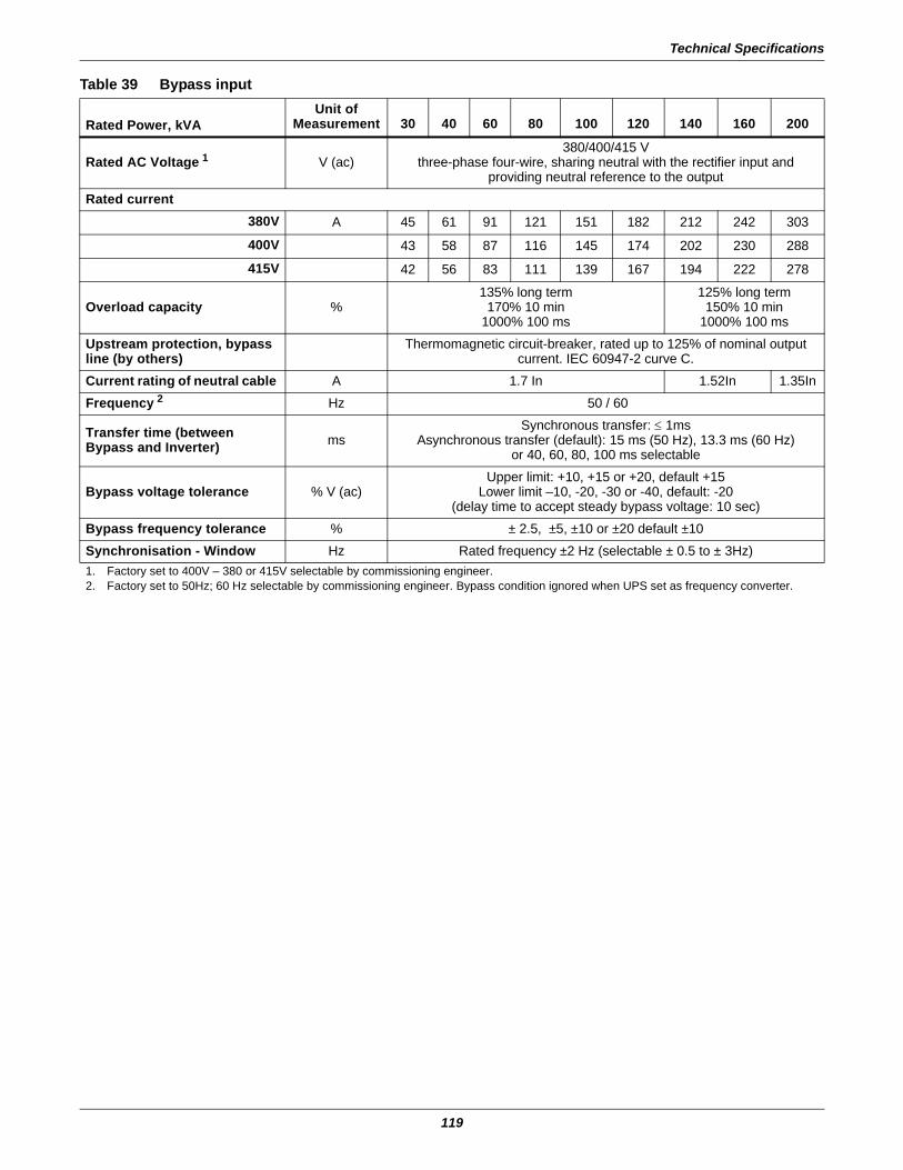
Technical Specifications
119
Table 39 Bypass input
Rated Power, kVAUnit of
Measurement 30 40 60 80 100 120 140 160 200
Rated AC Voltage 1 V (ac)380/400/415 V
three-phase four-wire, sharing neutral with the rectifier input andproviding neutral reference to the output
Rated current380V A 45 61 91 121 151 182 212 242 303
400V 43 58 87 116 145 174 202 230 288
415V 42 56 83 111 139 167 194 222 278
Overload capacity %135% long term
170% 10 min1000% 100 ms
125% long term150% 10 min
1000% 100 msUpstream protection, bypassline (by others)
Thermomagnetic circuit-breaker, rated up to 125% of nominal outputcurrent. IEC 60947-2 curve C.
Current rating of neutral cable A 1.7 In 1.52In 1.35InFrequency 2 Hz 50 / 60
Transfer time (between Bypass and Inverter) ms
Synchronous transfer: ≤ 1msAsynchronous transfer (default): 15 ms (50 Hz), 13.3 ms (60 Hz)
or 40, 60, 80, 100 ms selectable
Bypass voltage tolerance % V (ac)Upper limit: +10, +15 or +20, default +15
Lower limit –10, -20, -30 or -40, default: -20(delay time to accept steady bypass voltage: 10 sec)
Bypass frequency tolerance % ± 2.5, ±5, ±10 or ±20 default ±10Synchronisation - Window Hz Rated frequency ±2 Hz (selectable ± 0.5 to ± 3Hz)1. Factory set to 400V – 380 or 415V selectable by commissioning engineer.2. Factory set to 50Hz; 60 Hz selectable by commissioning engineer. Bypass condition ignored when UPS set as frequency converter.

EmersonNetworkPower.com
Ensuring The High Availability0f Mission-Critical Data And Applications.
Emerson Network Power, the global leader in enabling business-criticalcontinuity, ensures network resiliency and adaptability througha family of technologies—including Liebert power and coolingtechnologies—that protect and support business-critical systems.Liebert solutions employ an adaptive architecture that respondsto changes in criticality, density and capacity. Enterprises benefitfrom greater IT system availability, operational flexibility andreduced capital equipment and operating costs.
While every precaution has been taken to ensure the accuracyand completeness of this literature, Liebert Corporation assumes noresponsibility and disclaims all liability for damages resulting from use ofthis information or for any errors or omissions.© 2006 Liebert CorporationAll rights reserved throughout the world. Specifications subject to changewithout notice.® Liebert and the Liebert logo are registered trademarks of LiebertCorporation. All names referred to are trademarksor registered trademarks of their respective owners.
Technical Support / ServiceWeb Site
www.liebert.comMonitoring
Outside the US: 614-841-6755Single-Phase UPS
Outside the US: 614-841-6755Three-Phase UPS
Environmental Systems800-543-2778
Outside the United States614-888-0246
LocationsUnited States
1050 Dearborn DriveP.O. Box 29186
Columbus, OH 43229Europe
Via Leonardo Da Vinci 8Zona Industriale Tognana
35028 Piove Di Sacco (PD) Italy+39 049 9719 111
Fax: +39 049 5841 257Asia
7/F, Dah Sing Financial Centre108 Gloucester Road, Wanchai
Hong Kong852 2572220
Fax: 852 28029250
Emerson Network Power. The global leader in enabling Business-Critical Continuity™.
Business-Critical Continuity, Emerson Network Power and the Emerson Network Power logo are trademarks and service marks of Emerson Electric Co.
©2006 Emerson Electric Co.
Integrated Cabinet Solutio ns
AC Power Systems
Connectivity
DC Power Systems
Embedded ComputingEmbedded Power Power Switching & Controls
Precision Cooling
ServicesOutsid e PlantSite Monitoring
Surge & Signal Protection
SL-25230 (07/06) Rev. 5