Embed Size (px)
Citation preview


i Liebert SRC™ System Design Manual
Table of Content
1.0 Model Number and Nomenclature . . . . . . . . . . . . . . . . . . . . . . . . . . . . . . . 1
Acronyms . . . . . . . . . . . . . . . . . . . . . . . . . . . . . . . . . . . . . . . . . . . . . . . . . . . . . . 2
2.0 Product General Data . . . . . . . . . . . . . . . . . . . . . . . . . . . . . . . . . . . . . . . . . 3
2.1 Unit Specifications. . . . . . . . . . . . . . . . . . . . . . . . . . . . . . . . . . . . . . . . . . . . . . . . . . . . . . . . 3
2.2 Ship Loose Items. . . . . . . . . . . . . . . . . . . . . . . . . . . . . . . . . . . . . . . . . . . . . . . . . . . . . . . . . 5
3.0 Performance Data . . . . . . . . . . . . . . . . . . . . . . . . . . . . . . . . . . . . . . . . . . . . 9
3.1 Cooling Capacity . . . . . . . . . . . . . . . . . . . . . . . . . . . . . . . . . . . . . . . . . . . . . . . . . . . . . . . . . 9
3.2 Heating Capacity . . . . . . . . . . . . . . . . . . . . . . . . . . . . . . . . . . . . . . . . . . . . . . . . . . . . . . . . 12
3.3 Cooling/Heating Correction Factors . . . . . . . . . . . . . . . . . . . . . . . . . . . . . . . . . . . . . . . . . 14
3.4 Acoustic Data . . . . . . . . . . . . . . . . . . . . . . . . . . . . . . . . . . . . . . . . . . . . . . . . . . . . . . . . . . 16
3.5 Condensate Pump Performance. . . . . . . . . . . . . . . . . . . . . . . . . . . . . . . . . . . . . . . . . . . . 19
4.0 Dimensional Data . . . . . . . . . . . . . . . . . . . . . . . . . . . . . . . . . . . . . . . . . . . 21
4.1 SRC18 Unit Dimensions . . . . . . . . . . . . . . . . . . . . . . . . . . . . . . . . . . . . . . . . . . . . . . . . . . 21
4.2 SRC24 Unit Dimensions . . . . . . . . . . . . . . . . . . . . . . . . . . . . . . . . . . . . . . . . . . . . . . . . . . 23
4.3 SRC36 Unit Dimensions . . . . . . . . . . . . . . . . . . . . . . . . . . . . . . . . . . . . . . . . . . . . . . . . . . 25
4.4 Low Ambient Wind Baffle Dimensions . . . . . . . . . . . . . . . . . . . . . . . . . . . . . . . . . . . . . . . 27
4.5 Condensate Pump Dimensions. . . . . . . . . . . . . . . . . . . . . . . . . . . . . . . . . . . . . . . . . . . . . 30
5.0 Piping . . . . . . . . . . . . . . . . . . . . . . . . . . . . . . . . . . . . . . . . . . . . . . . . . . . . . 31
5.1 Refrigerant-flow Diagrams. . . . . . . . . . . . . . . . . . . . . . . . . . . . . . . . . . . . . . . . . . . . . . . . . 31
6.0 Electrical Data . . . . . . . . . . . . . . . . . . . . . . . . . . . . . . . . . . . . . . . . . . . . . . 35
6.1 SRC18 Unit Wiring Diagrams . . . . . . . . . . . . . . . . . . . . . . . . . . . . . . . . . . . . . . . . . . . . . . 35
6.2 SRC24 and SRC36 Unit Wiring Diagrams . . . . . . . . . . . . . . . . . . . . . . . . . . . . . . . . . . . . 37
6.3 Condensate-pump Wiring . . . . . . . . . . . . . . . . . . . . . . . . . . . . . . . . . . . . . . . . . . . . . . . . . 39

Liebert SRC™ System Design Manual ii
7.0 Application Guidelines . . . . . . . . . . . . . . . . . . . . . . . . . . . . . . . . . . . . . . . 41
7.1 Placement and Location Considerations. . . . . . . . . . . . . . . . . . . . . . . . . . . . . . . . . . . . . . 41
7.1.1 Indoor Unit Location . . . . . . . . . . . . . . . . . . . . . . . . . . . . . . . . . . . . . . . . . . . . . . . . . . . . . 42
7.1.1.1 Condensate Pump Location. . . . . . . . . . . . . . . . . . . . . . . . . . . . . . . . . . . . . . . . 42
7.1.2 Mounting the Outdoor Unit . . . . . . . . . . . . . . . . . . . . . . . . . . . . . . . . . . . . . . . . . . . . . . . . 43
7.1.2.1 Mounting Platform . . . . . . . . . . . . . . . . . . . . . . . . . . . . . . . . . . . . . . . . . . . . . . . 44
7.1.2.2 Tie-downs and Wind Restraints . . . . . . . . . . . . . . . . . . . . . . . . . . . . . . . . . . . . . 44
7.1.2.3 Snow and Ice Conditions . . . . . . . . . . . . . . . . . . . . . . . . . . . . . . . . . . . . . . . . . . 44
7.1.2.4 Outdoor Unit Clearance . . . . . . . . . . . . . . . . . . . . . . . . . . . . . . . . . . . . . . . . . . . 45
7.2 Refrigerant Piping Design . . . . . . . . . . . . . . . . . . . . . . . . . . . . . . . . . . . . . . . . . . . . . . . . . 48
7.2.1 Device Connection Limitations . . . . . . . . . . . . . . . . . . . . . . . . . . . . . . . . . . . . . . . . . . . . . 48
7.2.2 Selecting Field-supplied Copper Tubing . . . . . . . . . . . . . . . . . . . . . . . . . . . . . . . . . . . . . . 49
7.2.3 Piping Installation and Layout Best Practices . . . . . . . . . . . . . . . . . . . . . . . . . . . . . . . . . . 51
7.2.3.1 Layout Procedure. . . . . . . . . . . . . . . . . . . . . . . . . . . . . . . . . . . . . . . . . . . . . . . . 51
7.2.3.2 Using Elbows . . . . . . . . . . . . . . . . . . . . . . . . . . . . . . . . . . . . . . . . . . . . . . . . . . . 51
7.2.3.3 Field-provided Isolation Ball Valves . . . . . . . . . . . . . . . . . . . . . . . . . . . . . . . . . . 51
7.2.3.4 Obstacles . . . . . . . . . . . . . . . . . . . . . . . . . . . . . . . . . . . . . . . . . . . . . . . . . . . . . . 52
7.2.3.5 In-line Refrigeration Components . . . . . . . . . . . . . . . . . . . . . . . . . . . . . . . . . . . 52
7.2.3.6 No Pipe Size Substitutions. . . . . . . . . . . . . . . . . . . . . . . . . . . . . . . . . . . . . . . . . 52
7.2.3.7 Pipe Supports. . . . . . . . . . . . . . . . . . . . . . . . . . . . . . . . . . . . . . . . . . . . . . . . . . . 53
7.2.3.8 Pipe Sleeves at Penetrations . . . . . . . . . . . . . . . . . . . . . . . . . . . . . . . . . . . . . . . 54
7.2.3.9 Underground Refrigerant Piping . . . . . . . . . . . . . . . . . . . . . . . . . . . . . . . . . . . . 55
7.2.3.9.1 Brazing Practices . . . . . . . . . . . . . . . . . . . . . . . . . . . . . . . . . . . . . . . . . . . 56
7.2.3.10 Piping Insulation. . . . . . . . . . . . . . . . . . . . . . . . . . . . . . . . . . . . . . . . . . . . . . . . 56
7.2.3.11 Charging. . . . . . . . . . . . . . . . . . . . . . . . . . . . . . . . . . . . . . . . . . . . . . . . . . . . . . 57
7.3 Electrical Connections. . . . . . . . . . . . . . . . . . . . . . . . . . . . . . . . . . . . . . . . . . . . . . . . . . . . 57
7.3.1 Outdoor Electrical Connection . . . . . . . . . . . . . . . . . . . . . . . . . . . . . . . . . . . . . . . . . . . . . 57
iii Liebert SRC™ System Design Manual
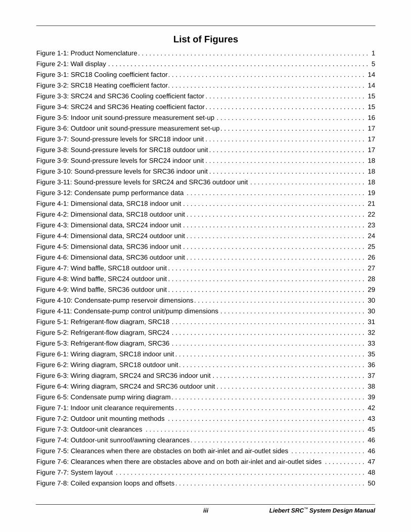
List of FiguresFigure 1-1: Product Nomenclature. . . . . . . . . . . . . . . . . . . . . . . . . . . . . . . . . . . . . . . . . . . . . . . . . . . . . . . . . . . . . . 1
Figure 2-1: Wall display . . . . . . . . . . . . . . . . . . . . . . . . . . . . . . . . . . . . . . . . . . . . . . . . . . . . . . . . . . . . . . . . . . . . . . 5
Figure 3-1: SRC18 Cooling coefficient factor. . . . . . . . . . . . . . . . . . . . . . . . . . . . . . . . . . . . . . . . . . . . . . . . . . . . . 14
Figure 3-2: SRC18 Heating coefficient factor. . . . . . . . . . . . . . . . . . . . . . . . . . . . . . . . . . . . . . . . . . . . . . . . . . . . . 14
Figure 3-3: SRC24 and SRC36 Cooling coefficient factor . . . . . . . . . . . . . . . . . . . . . . . . . . . . . . . . . . . . . . . . . . . 15
Figure 3-4: SRC24 and SRC36 Heating coefficient factor . . . . . . . . . . . . . . . . . . . . . . . . . . . . . . . . . . . . . . . . . . . 15
Figure 3-5: Indoor unit sound-pressure measurement set-up . . . . . . . . . . . . . . . . . . . . . . . . . . . . . . . . . . . . . . . . 16
Figure 3-6: Outdoor unit sound-pressure measurement set-up. . . . . . . . . . . . . . . . . . . . . . . . . . . . . . . . . . . . . . . 17
Figure 3-7: Sound-pressure levels for SRC18 indoor unit . . . . . . . . . . . . . . . . . . . . . . . . . . . . . . . . . . . . . . . . . . . 17
Figure 3-8: Sound-pressure levels for SRC18 outdoor unit . . . . . . . . . . . . . . . . . . . . . . . . . . . . . . . . . . . . . . . . . . 17
Figure 3-9: Sound-pressure levels for SRC24 indoor unit . . . . . . . . . . . . . . . . . . . . . . . . . . . . . . . . . . . . . . . . . . . 18
Figure 3-10: Sound-pressure levels for SRC36 indoor unit . . . . . . . . . . . . . . . . . . . . . . . . . . . . . . . . . . . . . . . . . . 18
Figure 3-11: Sound-pressure levels for SRC24 and SRC36 outdoor unit . . . . . . . . . . . . . . . . . . . . . . . . . . . . . . . 18
Figure 3-12: Condensate pump performance data . . . . . . . . . . . . . . . . . . . . . . . . . . . . . . . . . . . . . . . . . . . . . . . . 19
Figure 4-1: Dimensional data, SRC18 indoor unit . . . . . . . . . . . . . . . . . . . . . . . . . . . . . . . . . . . . . . . . . . . . . . . . . 21
Figure 4-2: Dimensional data, SRC18 outdoor unit . . . . . . . . . . . . . . . . . . . . . . . . . . . . . . . . . . . . . . . . . . . . . . . . 22
Figure 4-3: Dimensional data, SRC24 indoor unit . . . . . . . . . . . . . . . . . . . . . . . . . . . . . . . . . . . . . . . . . . . . . . . . . 23
Figure 4-4: Dimensional data, SRC24 outdoor unit . . . . . . . . . . . . . . . . . . . . . . . . . . . . . . . . . . . . . . . . . . . . . . . . 24
Figure 4-5: Dimensional data, SRC36 indoor unit . . . . . . . . . . . . . . . . . . . . . . . . . . . . . . . . . . . . . . . . . . . . . . . . . 25
Figure 4-6: Dimensional data, SRC36 outdoor unit . . . . . . . . . . . . . . . . . . . . . . . . . . . . . . . . . . . . . . . . . . . . . . . . 26
Figure 4-7: Wind baffle, SRC18 outdoor unit . . . . . . . . . . . . . . . . . . . . . . . . . . . . . . . . . . . . . . . . . . . . . . . . . . . . . 27
Figure 4-8: Wind baffle, SRC24 outdoor unit . . . . . . . . . . . . . . . . . . . . . . . . . . . . . . . . . . . . . . . . . . . . . . . . . . . . . 28
Figure 4-9: Wind baffle, SRC36 outdoor unit . . . . . . . . . . . . . . . . . . . . . . . . . . . . . . . . . . . . . . . . . . . . . . . . . . . . . 29
Figure 4-10: Condensate-pump reservoir dimensions. . . . . . . . . . . . . . . . . . . . . . . . . . . . . . . . . . . . . . . . . . . . . . 30
Figure 4-11: Condensate-pump control unit/pump dimensions . . . . . . . . . . . . . . . . . . . . . . . . . . . . . . . . . . . . . . . 30
Figure 5-1: Refrigerant-flow diagram, SRC18 . . . . . . . . . . . . . . . . . . . . . . . . . . . . . . . . . . . . . . . . . . . . . . . . . . . . 31
Figure 5-2: Refrigerant-flow diagram, SRC24 . . . . . . . . . . . . . . . . . . . . . . . . . . . . . . . . . . . . . . . . . . . . . . . . . . . . 32
Figure 5-3: Refrigerant-flow diagram, SRC36 . . . . . . . . . . . . . . . . . . . . . . . . . . . . . . . . . . . . . . . . . . . . . . . . . . . . 33
Figure 6-1: Wiring diagram, SRC18 indoor unit . . . . . . . . . . . . . . . . . . . . . . . . . . . . . . . . . . . . . . . . . . . . . . . . . . . 35
Figure 6-2: Wiring diagram, SRC18 outdoor unit . . . . . . . . . . . . . . . . . . . . . . . . . . . . . . . . . . . . . . . . . . . . . . . . . . 36
Figure 6-3: Wiring diagram, SRC24 and SRC36 indoor unit . . . . . . . . . . . . . . . . . . . . . . . . . . . . . . . . . . . . . . . . . 37
Figure 6-4: Wiring diagram, SRC24 and SRC36 outdoor unit . . . . . . . . . . . . . . . . . . . . . . . . . . . . . . . . . . . . . . . . 38
Figure 6-5: Condensate pump wiring diagram. . . . . . . . . . . . . . . . . . . . . . . . . . . . . . . . . . . . . . . . . . . . . . . . . . . . 39
Figure 7-1: Indoor unit clearance requirements . . . . . . . . . . . . . . . . . . . . . . . . . . . . . . . . . . . . . . . . . . . . . . . . . . . 42
Figure 7-2: Outdoor unit mounting methods . . . . . . . . . . . . . . . . . . . . . . . . . . . . . . . . . . . . . . . . . . . . . . . . . . . . . 43
Figure 7-3: Outdoor-unit clearances . . . . . . . . . . . . . . . . . . . . . . . . . . . . . . . . . . . . . . . . . . . . . . . . . . . . . . . . . . . 45
Figure 7-4: Outdoor-unit sunroof/awning clearances. . . . . . . . . . . . . . . . . . . . . . . . . . . . . . . . . . . . . . . . . . . . . . . 46
Figure 7-5: Clearances when there are obstacles on both air-inlet and air-outlet sides . . . . . . . . . . . . . . . . . . . . 46
Figure 7-6: Clearances when there are obstacles above and on both air-inlet and air-outlet sides . . . . . . . . . . . 47
Figure 7-7: System layout . . . . . . . . . . . . . . . . . . . . . . . . . . . . . . . . . . . . . . . . . . . . . . . . . . . . . . . . . . . . . . . . . . . 48
Figure 7-8: Coiled expansion loops and offsets . . . . . . . . . . . . . . . . . . . . . . . . . . . . . . . . . . . . . . . . . . . . . . . . . . . 50

Liebert SRC™ System Design Manual iv
Figure 7-9: Installing piping above and below an obstacle . . . . . . . . . . . . . . . . . . . . . . . . . . . . . . . . . . . . . . . . . . 52
Figure 7-10: Pipe-hanger details . . . . . . . . . . . . . . . . . . . . . . . . . . . . . . . . . . . . . . . . . . . . . . . . . . . . . . . . . . . . . . 53
Figure 7-11: Typical pipe-support location for a change in pipe direction . . . . . . . . . . . . . . . . . . . . . . . . . . . . . . . 53
Figure 7-12: Pipe sleeve options . . . . . . . . . . . . . . . . . . . . . . . . . . . . . . . . . . . . . . . . . . . . . . . . . . . . . . . . . . . . . . 54
Figure 7-13: Typical arrangement of pipe and cables in a utility conduit . . . . . . . . . . . . . . . . . . . . . . . . . . . . . . . . 55
Figure 7-14: Refrigerant-pipe brazing . . . . . . . . . . . . . . . . . . . . . . . . . . . . . . . . . . . . . . . . . . . . . . . . . . . . . . . . . . 56
Figure 7-15: Circuit breaker wiring. . . . . . . . . . . . . . . . . . . . . . . . . . . . . . . . . . . . . . . . . . . . . . . . . . . . . . . . . . . . . 58
Figure 7-16: Outdoor-unit terminal-block connections . . . . . . . . . . . . . . . . . . . . . . . . . . . . . . . . . . . . . . . . . . . . . . 58
v Liebert SRC™ System Design Manual
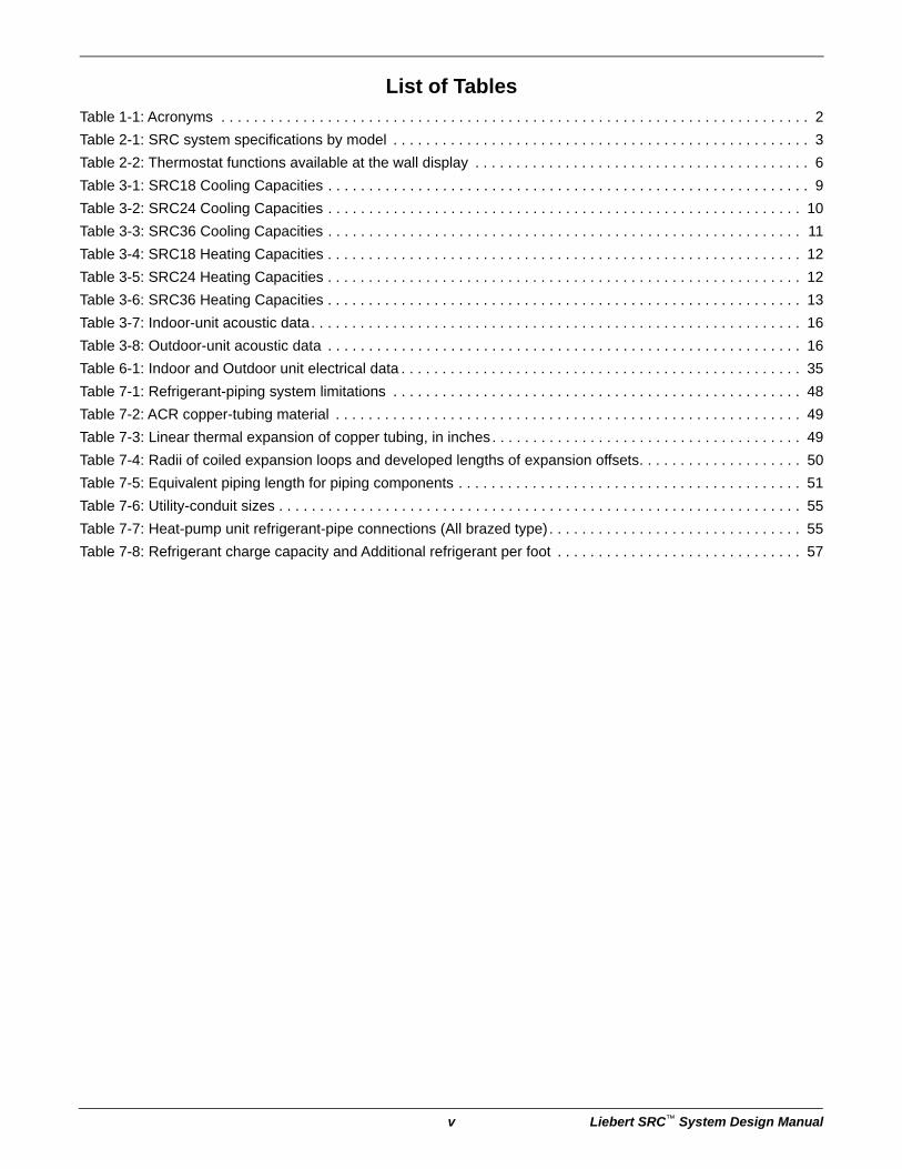
List of TablesTable 1-1: Acronyms . . . . . . . . . . . . . . . . . . . . . . . . . . . . . . . . . . . . . . . . . . . . . . . . . . . . . . . . . . . . . . . . . . . . . . . . 2
Table 2-1: SRC system specifications by model . . . . . . . . . . . . . . . . . . . . . . . . . . . . . . . . . . . . . . . . . . . . . . . . . . . 3
Table 2-2: Thermostat functions available at the wall display . . . . . . . . . . . . . . . . . . . . . . . . . . . . . . . . . . . . . . . . . 6
Table 3-1: SRC18 Cooling Capacities . . . . . . . . . . . . . . . . . . . . . . . . . . . . . . . . . . . . . . . . . . . . . . . . . . . . . . . . . . . 9
Table 3-2: SRC24 Cooling Capacities . . . . . . . . . . . . . . . . . . . . . . . . . . . . . . . . . . . . . . . . . . . . . . . . . . . . . . . . . . 10
Table 3-3: SRC36 Cooling Capacities . . . . . . . . . . . . . . . . . . . . . . . . . . . . . . . . . . . . . . . . . . . . . . . . . . . . . . . . . . 11
Table 3-4: SRC18 Heating Capacities . . . . . . . . . . . . . . . . . . . . . . . . . . . . . . . . . . . . . . . . . . . . . . . . . . . . . . . . . . 12
Table 3-5: SRC24 Heating Capacities . . . . . . . . . . . . . . . . . . . . . . . . . . . . . . . . . . . . . . . . . . . . . . . . . . . . . . . . . . 12
Table 3-6: SRC36 Heating Capacities . . . . . . . . . . . . . . . . . . . . . . . . . . . . . . . . . . . . . . . . . . . . . . . . . . . . . . . . . . 13
Table 3-7: Indoor-unit acoustic data. . . . . . . . . . . . . . . . . . . . . . . . . . . . . . . . . . . . . . . . . . . . . . . . . . . . . . . . . . . . 16
Table 3-8: Outdoor-unit acoustic data . . . . . . . . . . . . . . . . . . . . . . . . . . . . . . . . . . . . . . . . . . . . . . . . . . . . . . . . . . 16
Table 6-1: Indoor and Outdoor unit electrical data . . . . . . . . . . . . . . . . . . . . . . . . . . . . . . . . . . . . . . . . . . . . . . . . . 35
Table 7-1: Refrigerant-piping system limitations . . . . . . . . . . . . . . . . . . . . . . . . . . . . . . . . . . . . . . . . . . . . . . . . . . 48
Table 7-2: ACR copper-tubing material . . . . . . . . . . . . . . . . . . . . . . . . . . . . . . . . . . . . . . . . . . . . . . . . . . . . . . . . . 49
Table 7-3: Linear thermal expansion of copper tubing, in inches. . . . . . . . . . . . . . . . . . . . . . . . . . . . . . . . . . . . . . 49
Table 7-4: Radii of coiled expansion loops and developed lengths of expansion offsets. . . . . . . . . . . . . . . . . . . . 50
Table 7-5: Equivalent piping length for piping components . . . . . . . . . . . . . . . . . . . . . . . . . . . . . . . . . . . . . . . . . . 51
Table 7-6: Utility-conduit sizes . . . . . . . . . . . . . . . . . . . . . . . . . . . . . . . . . . . . . . . . . . . . . . . . . . . . . . . . . . . . . . . . 55
Table 7-7: Heat-pump unit refrigerant-pipe connections (All brazed type) . . . . . . . . . . . . . . . . . . . . . . . . . . . . . . . 55
Table 7-8: Refrigerant charge capacity and Additional refrigerant per foot . . . . . . . . . . . . . . . . . . . . . . . . . . . . . . 57

Liebert SRC™ System Design Manual vi
Page intentionally left blank.

1 Liebert® SRC™ System Design Manual
1.0 Model Number and Nomenclature
Figure 1-1 Product Nomenclature
H 00N
AHRI TypeH = Heat pump
PlaceholderNominal Capacity (in Btu/h)18 = 18,00024 = 24,00036 = 36,000
Revision
Example: SRC24 HPN000
P
VoltageP = 208 – 230/1/60
24
Unit TypeN = Indoor evaporatorC = Outdoor condensing unit
0
Placeholder
SRC

Acronyms
Liebert® SRC™ System Design Manual 2
AcronymsTable 1-1 Acronyms
ABS Acrylonitrile Butadiene Styrene H/M/L High/Medium/Low
AC Air Conditioner HVAC Heating, ventilation and air conditioning
ACP Advanced control platform IDU Indoor unit
ASHRAEAmerican Society of Heating, Refrigeration, and
Air ConditioningISO International Organization for Standardization
AWG American Wire Gauge kW kilowatts
BLDC Brush-less digitally-controlled/direct LED Light-emitting diode
Btu/h British Thermal Units per hour MBh Thousands BTUs per hour
BUS Binary unit system MCA Maximum circuit ampacity
CFM Cubic feet per minute MOP Maximum overcurrent protection
COP Coefficient of performance ODU Outdoor unit
CR Combination ratio PCB Printed circuit board
DB Dry bulb PCM Pre-coated metal
dB(A) Decibels with “A” frequency weighting PDI Power distribution indicator
DDOAS Decoupled dedicated outdoor air PI Power input
DO Digital output PTAC Packaged terminal air conditioner
DPST Double-pole single-throw (switch) PVC Polyvinyl Chloride
EEV Electronic expansion valve USB Universal serial BUS
ELF Equivalent length in feet VAC Voltage alternating current
ESP External static pressure VAV Variable air volume
ETL Electronic Testing Laboratories VRF Variable refrigerant flow
HIPS High-impact Polystyrene WB Wet bulb

Unit Specifications
3 Liebert® SRC™ System Design Manual
2.0 Product General Data
2.1 Unit SpecificationsTable 2-1 SRC system specifications by model
SRC18 SRC24 SRC36
Nominal Cooling Capacity (Btu/h) 18,200 22,000 33,000
Cooling Power Input 1 (kW) 1.45 1.7 4.0
Nominal Heating Capacity1 (Btu/h) 22,000 27,000 35,200
Heating Power Input1 (kW) 1.76 2.3 3.8
Cooling COP 3.66 3.66 2.40
Maximum Heating Capacity, Btu/h (kW)
Outdoor 17°F (WB)/Indoor 70°F (DB) 18,040 (5.3) 27,410 (8.0) 35,740 (10.5)
Outdoor 5°F (WB)/Indoor 70° (DB) 15,180 (4.4) 23,690 (6.9) 30,890 (9.1)
Outdoor –4°F (WB)/Indoor 70 °F (DB) 14,740 (4.3) 20,580 (6.0) 26,820 (7.9)
EER 12.6 12.5 8.2
SEER 20.5 21.0 16.5
HSPF 9.7 11 10
Power Supply (V/Hz/∅) 208 – 230/60/1
Outdoor-unit Operating Range2
Cooling (°F) 14 – 118
Heating (°F) –4 to 65 –4 to 75
Indoor-unit Operating Range
Cooling (°F) 53 to 75 64 to 90
Heating (°F) 60 to 86
Indoor Temperature Setting Range
Cooling (°F) 64 to 86
Heating (°F) 60 to 86
Unit Data
Refrigerant Type3 R410A
Refrigerant Control Electronic Expansion Valve
Indoor Unit Sound Pressure4 dB(A) (H/M/L/Sleep) 45/40/35/29 49/44/40
Outdoor Unit Sound Pressure4 dB(A) 53 55
Power/Communication Cable5 (No. x AWG) 4 x 18
1. Power Input is rated at high speed.2. Optional low Ambient Wind Baffle Kit allows operation down to 0°F in cooling mode.3. Take appropriate actions at the end of HVAC equipment life to recover, recycle, reclaim or destroy R410A refrigerant according to
applicable regulations (40 CFR Part 82, Subpart F) under section 608 of CAA.4. Sound Pressure levels are tested in an anechoic chamber under ISO Standard 1996.5. All power wiring/communication cables are field-supplied and are to be minimum 18 AWG, 4-conductor, stranded, shielded and must
comply with applicable local and national codes.6. Piping lengths are equivalent.The unit comes with a dry helium charge.This data is rated 0 ft above sea level with 24.6 of refrigerant liner per indoor unit and a 0 ft level difference outdoor and indoor units.Cooling capacity rating obtained with air entering the indoor unit a 80°F dry bulb (DB) and 67°F wet bulb (WB) and outdoor ambient conditions of 95°F DB and 75°F WB.Heating capacity rating obtained with air entering the indoor unit at 70°F DB and 59°F WB and outdoor ambient conditions of 47°F DB and 43°F WB.

Product General Data
Liebert® SRC™ System Design Manual 4
Unit Weights
Indoor Unit Net/Shipping Weight, lb (kg) 31/36 (14.1/16.3) 40/46 (18.1/20.9)
Outdoor Unit Net/Shipping Weight, lb (kg) 121/131 (54.9/59.4) 125/133 (56.7/60.3)
Compressor
Compressor Type (Qty) Twin Rotary (1)
Fan
Indoor Unit Type (Qty) Cross Flow (1)
Outdoor Unit Type (Qty) Propeller (1)
Motor/Drive Brush-less Digitally-controlled/Direct
Airflow Rate
Indoor Unit Max/H/M/L (CFM) 735/622/509/399 848/706/530/459
Outdoor Unit Max (CFM) 2,119
Piping
Liquid Line (in., OD) 3/8
Vapor Line (in., OD) 5/8
Condensation Line (OD, ID) 27/32, 5/8
Additional Refrigerant Charge (oz/ft) 0.38
Pipe Length6 (Minimum/Maximum) (ft) 9.84/98.4 0/164
Piping Length6 (no additional refrigerant, ft) 24.6
Max Elevation Difference (ft) 49.2 98.4
Table 2-1 SRC system specifications by model (continued)
SRC18 SRC24 SRC36
1. Power Input is rated at high speed.2. Optional low Ambient Wind Baffle Kit allows operation down to 0°F in cooling mode.3. Take appropriate actions at the end of HVAC equipment life to recover, recycle, reclaim or destroy R410A refrigerant according to
applicable regulations (40 CFR Part 82, Subpart F) under section 608 of CAA.4. Sound Pressure levels are tested in an anechoic chamber under ISO Standard 1996.5. All power wiring/communication cables are field-supplied and are to be minimum 18 AWG, 4-conductor, stranded, shielded and must
comply with applicable local and national codes.6. Piping lengths are equivalent.The unit comes with a dry helium charge.This data is rated 0 ft above sea level with 24.6 of refrigerant liner per indoor unit and a 0 ft level difference outdoor and indoor units.Cooling capacity rating obtained with air entering the indoor unit a 80°F dry bulb (DB) and 67°F wet bulb (WB) and outdoor ambient conditions of 95°F DB and 75°F WB.Heating capacity rating obtained with air entering the indoor unit at 70°F DB and 59°F WB and outdoor ambient conditions of 47°F DB and 43°F WB.

Ship Loose Items
5 Liebert® SRC™ System Design Manual
2.2 Ship Loose Items• Wired Wall Display—Shown in Figure 2-1, allows control of indoor unit on/off, operation mode,
occupied and unoccupied temperature setpoints, fan speed and air-flow directions for up to 8 indoor units. Programmable schedule with 5 events per day with control of occupied/unoccupied, on/off, mode, setpoints and fan speed. Advanced functions include two setpoint auto-changeover, minimum difference between setpoints, setback and timed override. TABLE lists the functions available at the wall box, the type of function, and the models on which it is available.
• Maximum wire length = 164 ft
• Condensate Pump—Complete with integral float switch, safety switch, pump and motor assembly with a capacity of 1 GPH (3.8 LPH) @ 10 ft (3 m) head.
• Low Ambient Wind Baffle—Allows operation of cooling mode down to 0°F. See Figures 4-7 to 4-9 in Section 4.0.
Figure 2-1 Wall display
No. Description No. Description
1 Operation indication 10 Air-flow button
2 Set temperature button 11 Cooling temperature setpoint
3 Fan speed button 12 Function setting button
4 Set back button 13 Up, down, left and right buttons
5 Operation-mode select button 14 On/Off button
6Wireless thermostat receiver(not included on some models)
15 Heating temperature setpoint
7 Sub function button 16 Set/Cancel button
8 Ventilation button 17 Exit button
9 Reservation button

Product General Data
Liebert® SRC™ System Design Manual 6
Table 2-2 Thermostat functions available at the wall display
Category Function SRC18 SRC24 SRC36
Operation functions
Standard Operation- Cooling Mode
Standard Operation- Power Cooling
Standard Operation- Heating Mode
Standard Operation- Dehumidification Mode
Standard Operation- Fan Mode
Standard Operation- Auto Operation Mode (2Set point Control)
Standard Operation- Auto Operation Mode (1Set point Control)
Standard Operation- Time Override
Standard Operation- Set back
Standard Operation- Hold
Standard Operation- Temperature Setting
Standard Operation- Airflow Setting
Sub Function- Energy-Saving Cooling Operation
Sub Function- Automatic Drying
Sub Function- Fan Auto
Function Setting- Vane Angle Control
Function Setting- Child Lock
Function Setting- Minimum Difference Between Heating and Cooling Set Points (2Set point Control)
Function Setting- Auto Change over Change temperature(1Set point Control)
Function Setting- Changing Current Time
Function Setting- Override set time
Function Setting- Set back temperature
Programming- Simple Reservation
Programming- Sleep Reservation
Programming- Weekly Reservation
Programming- Weekly Reservation Schedule Copy/Paste
Programming- Holiday Reservation
Programming- Delete All Reservation
Troubleshooting Mode Self Diagnosis
Checkups Before Reporting Breakdown

Ship Loose Items
7 Liebert® SRC™ System Design Manual
Installation functions
Installer Setting- How to enter installer setting mode
Installer Setting- Test Run Mode
Installer Setting- Setting Address of Central Control
Installer Setting- Thermistor
Installer Setting- Dry Contact Mode Setting
Installer Setting- Fahrenheit / Celsius Switching
Installer Setting- Check indoor unit Address Number
Installer Setting- Set point range Lock
Installer Setting- Fan operation in the colling mode and thermal off conditions
Installer Setting- Hold Enable / Disable
Installer Setting- Indoor unit Auto Start setting
Installer Setting- Setting for Simple Dry contact unit
Table 2-2 Thermostat functions available at the wall display (continued)
Category Function SRC18 SRC24 SRC36

Product General Data
Liebert® SRC™ System Design Manual 8
Page intentionally left blank.

Cooling Capacity
9 Liebert® SRC™ System Design Manual
3.0 Performance Data
3.1 Cooling CapacityTable 3-1 SRC18 Cooling Capacities
Outdoor Air Temp (°F DB)
Indoor Air Temp (°F DB / °F WB)
64 / 53 68 / 57 72 / 61 77 / 64 80 / 67 86 / 72 90 / 75
TC SHC PI TC SHC PI TC SHC PI TC SHC PI TC SHC PI TC SHC PI TC SHC PI
04 11.02 8.83 0.56 13.78 9.41 0.67 16.54 9.98 0.77 19.99 10.70 0.90 22.06 11.12 0.98 18.40 12.13 0.80 15.97 12.80 0.68
54 10.81 8.71 0.59 13.51 9.27 0.70 16.22 9.84 0.81 19.60 10.54 0.94 21.63 10.97 1.02 18.05 11.96 0.83 15.66 12.62 0.71
74 10.88 8.79 0.60 13.61 9.36 0.70 16.33 9.93 0.81 19.74 10.64 0.95 21.78 11.07 1.03 18.18 12.07 0.84 15.77 12.74 0.71
104 10.99 8.91 0.61 13.75 9.49 0.72 16.50 10.06 0.83 19.94 10.79 0.97 22.01 11.22 1.05 18.36 12.23 0.86 15.93 12.91 0.73
14 11.14 8.97 0.91 11.98 9.64 0.63 12.81 10.31 0.65 13.64 10.98 0.67 14.03 11.29 0.69 15.31 12.33 0.72 16.15 13.00 0.74
23 11.96 9.63 0.61 12.86 10.35 0.63 13.75 11.07 0.65 14.65 11.79 0.67 15.06 12.12 0.69 16.44 13.23 0.72 17.34 13.96 0.74
25 12.13 9.77 0.62 13.03 10.49 0.64 13.92 11.21 0.66 14.82 11.93 0.68 15.23 12.26 0.70 16.61 13.37 0.73 17.51 14.09 0.75
30 12.60 10.15 0.67 13.52 10.88 0.69 14.44 11.62 0.71 15.32 12.33 0.73 15.74 12.67 0.76 17.13 13.79 0.79 18.09 14.56 0.81
35 13.08 10.53 0.72 14.02 11.28 0.74 14.95 12.04 0.76 15.81 12.73 0.78 16.25 13.08 0.81 17.65 14.21 0.84 18.67 15.03 0.86
40 13.55 10.91 0.76 14.51 11.68 0.79 15.47 12.45 0.81 16.31 13.13 0.83 16.77 13.50 0.86 18.17 14.63 0.89 19.25 15.50 0.92
45 14.02 11.29 0.81 15.00 12.08 0.83 15.99 12.87 0.86 16.81 13.53 0.89 17.28 13.91 0.91 18.69 15.05 0.95 19.84 15.97 0.98
50 14.49 11.67 0.85 15.50 12.47 0.88 16.50 13.28 0.91 17.30 13.93 0.94 17.79 14.32 0.96 19.21 15.47 1.00 20.42 16.44 1.03
55 14.96 12.05 0.90 15.99 12.87 0.93 17.02 13.70 0.96 17.80 14.33 0.99 18.30 14.73 1.02 19.73 15.88 1.06 21.00 16.91 1.09
60 15.44 12.43 0.95 16.48 13.27 0.98 17.53 14.11 1.01 18.30 14.73 1.04 18.81 15.15 1.07 20.25 16.30 1.11 21.58 17.38 1.14
65 15.91 12.81 0.99 16.98 13.67 1.02 18.05 14.53 1.05 18.79 15.13 1.09 19.33 15.56 1.12 20.77 16.72 1.17 22.17 17.81 1.20
70 16.38 13.19 1.04 17.47 14.06 1.07 18.56 14.94 1.10 19.29 15.53 1.14 19.84 15.97 1.17 21.29 17.14 1.22 22.75 18.3 1.26
75 16.17 13.02 1.07 17.27 13.90 1.10 18.36 14.78 1.14 19.11 15.38 1.17 19.66 15.82 1.21 21.02 16.92 1.25 22.57 18.17 1.29
80 15.75 12.68 1.11 16.84 13.56 1.15 17.93 14.44 1.18 18.75 15.09 1.22 19.47 15.68 1.26 20.75 16.70 1.31 22.20 17.87 1.35
85 15.33 12.34 1.19 16.42 13.22 1.23 17.51 14.09 1.27 18.38 14.90 1.31 19.11 15.38 1.35 20.48 16.48 1.40 21.87 17.61 1.44
90 14.91 12.00 1.24 16.00 12.88 1.28 17.08 13.75 1.32 18.02 14.50 1.36 18.75 15.09 1.40 20.20 16.26 1.46 21.44 17.26 1.50
95 14.46 11.64 1.28 15.54 12.51 1.32 16.62 13.38 1.36 17.70 14.25 1.40 18.20 14.65 1.45 19.87 15.99 1.50 20.95 16.87 1.55
100 14.08 11.33 1.30 15.16 12.20 1.37 16.24 13.08 1.38 17.32 13.95 1.43 17.96 14.46 1.47 19.49 15.69 1.53 20.57 16.56 1.58
105 13.70 11.03 1.32 14.78 11.90 1.36 15.86 12.77 1.41 16.95 13.64 1.45 17.73 14.27 1.50 19.11 15.38 1.56 20.19 16.26 1.60
110 13.32 10.72 1.34 14.40 11.59 1.38 15.49 12.47 1.42 16.57 13.34 1.47 17.35 13.97 1.51 18.73 15.08 1.57 19.82 15.95 1.62
115 12.94 10.42 1.35 14.02 11.29 1.39 15.11 12.16 1.44 16.19 13.03 1.48 16.97 13.66 1.53 18.35 14.78 1.59 19.44 15.65 1.64
118 12.56 10.11 1.36 13.65 10.99 1.41 14.56 11.72 1.45 15.65 12.60 1.49 16.38 13.19 1.54 17.75 14.28 1.60 18.75 15.09 1.65
122 11.96 9.63 1.37 12.99 10.45 1.41 14.01 11.28 1.46 15.04 12.10 1.50 15.78 12.70 1.55 17.09 13.75 1.61 18.11 14.58 1.66
DB = Dry Bulb Temperature (°F), WB = Wet Bulb Temperature (°F), TC = Total Capacity (kBtuh), SHC = Sensible Capacity (kBtuh)PI = Power Input (kW) (includes compressor, indoor fan motor, and outdoor fan motor)1. All capacities are net, evaporator fan motor is heat deducted.2. Grey shading indicates reference data. When operating the unit at this temperature, these values can be different by discontinuous operation.3. Direct interpolation is permissible. Do not extrapolate.4. Capacities at less than 14° require a wind baffle.Nominal capacity as rated: 0 ft above seal level with 25 ft of refrigerant piping. 0 ft. level difference between outdoor and indoor units.Nominal cooling capacity rating obtained with air entering the indoor unit at 80°F DB and 67°F WB, and outdoor ambient conditions of 95°F DB and 75°F WB.

Performance Data
Liebert® SRC™ System Design Manual 10
Table 3-2 SRC24 Cooling Capacities
Outdoor Air Temp (°F DB)
Indoor Air Temp (°F DB / °F WB)
64 / 53 68 / 57 72 / 61 77 / 64 80 / 67 86 / 72 90 / 75
TC SHC PI TC SHC PI TC SHC PI TC SHC PI TC SHC PI TC SHC PI TC SHC PI
04 13.32 11.54 0.68 16.66 12.29 0.81 19.99 13.04 0.93 24.16 13.97 1.09 26.66 14.53 1.19 22.25 15.85 0.97 19.30 16.73 0.82
54 13.07 11.38 0.72 16.34 12.11 0.85 19.61 12.85 0.98 23.70 13.77 1.14 26.15 14.33 1.24 21.82 15.62 1.01 18.93 16.49 0.86
74 13.16 11.48 0.72 16.45 12.23 0.86 19.74 12.97 0.99 23.86 13.90 1.15 26.33 14.46 1.25 21.97 15.77 1.02 19.06 16.64 0.87
104 13.29 11.64 0.73 16.62 12.39 0.87 19.95 13.15 1.00 24.10 14.09 1.17 26.60 14.66 1.27 22.20 15.98 1.04 19.26 16.87 0.88
14 12.81 9.92 0.75 14.04 10.87 0.77 14.83 11.48 0.79 15.83 12.26 0.82 16.74 12.96 0.84 17.41 13.48 0.88 18.86 14.60 0.90
17 12.92 10.00 0.75 14.39 11.14 0.77 15.21 11.77 0.79 16.24 12.57 0.82 17.37 13.45 0.84 18.08 14.00 0.88 19.34 14.97 0.90
23 14.31 11.08 0.74 15.38 11.91 0.77 16.45 12.74 0.79 17.52 13.57 0.81 18.85 14.59 0.84 19.66 15.22 0.87 20.73 1605 0.90
59 17.35 13.43 0.86 18.65 14.44 0.88 19.95 15.45 0.91 21.25 16.45 0.94 21.84 16.91 0.97 23.85 18.46 1.01 25.14 19.47 1.04
70 19.80 15.33 1.26 21.12 16.35 1.30 22.44 17.38 1.34 23.32 18.06 1.38 23.98 18.57 1.43 25.74 19.93 1.48 27.50 21.29 1.53
75 19.55 15.13 1.30 20.87 16.16 1.34 22.20 17.19 1.38 23.10 17.89 1.42 23.76 18.40 1.47 25.41 19.67 1.53 27.28 21.12 1.57
80 19.03 14.74 1.36 20.36 15.76 1.40 21.68 16.79 1.44 22.66 17.55 1.49 23.54 18.23 1.53 25.08 19.42 1.59 26.84 20.78 1.64
85 18.53 14.35 1.45 19.85 15.37 1.49 21.16 16.39 1.54 22.22 17.20 1.59 23.10 17.89 1.64 24.75 19.16 1.70 26.44 20.47 1.75
90 18.02 13.95 1.51 19.34 14.97 1.56 20.65 15.99 1.61 21.78 16.86 1.66 22.66 17.55 1.71 24.42 18.91 1.78 25.91 20.06 1.83
95 17.47 13.53 1.56 18.78 14.54 1.61 20.09 15.56 1.66 21.40 16.57 1.71 22.00 17.03 .76 24.02 18.60 1.83 25.33 19.61 1.89
100 17.02 13.18 1.58 18.33 14.19 1.63 19.63 15.20 1.68 20.94 16.22 1.74 21.71 16.81 1.79 23.56 18.24 1.86 24.87 19.26 1.92
105 16.56 12.82 1.61 17.87 13.84 1.66 19.18 14.85 1.71 20.48 15.86 1.76 21.43 16.59 1.82 23.10 17.89 1.89 24.41 18.90 1.95
110 16.10 12.47 1.63 17.41 13.48 1.68 18.72 14.49 1.73 20.03 15.51 1.78 20.97 16.24 1.84 22.64 17.53 1.91 23.95 18.55 1.97
115 15.64 12.11 1.64 16.95 13.13 1.69 18.26 14.14 1.75 19.57 15.15 1.80 20.50 15.88 1.86 22.19 17.18 1.93 23.50 18.19 1.99
118 15.18 11.75 1.66 16.50 12.78 1.71 17.60 13.63 1.75 18.92 14.65 1.82 19.80 15.33 1.87 21.45 16.61 1.95 22.66 17.55 2.01
DB = Dry Bulb Temperature (°F), WB = Wet Bulb Temperature (°F), TC = Total Capacity (kBtuh), SHC = Sensible Capacity (kBtuh)PI = Power Input (kW) (includes compressor, indoor fan motor, and outdoor fan motor)1. All capacities are net, evaporator fan motor is heat deducted.2. Grey shading indicates reference data. When operating the unit at this temperature, these values can be different by discontinuous operation.3. Direct interpolation is permissible. Do not extrapolate.4. Capacities at less than 14° require a wind baffle.Nominal capacity as rated: 0 ft above seal level with 25 ft of refrigerant piping. 0 ft. level difference between outdoor and indoor units.Nominal cooling capacity rating obtained with air entering the indoor unit at 80°F DB and 67°F WB, and outdoor ambient conditions of 95°F DB and 75°F WB.

Cooling Capacity
11 Liebert® SRC™ System Design Manual
Table 3-3 SRC36 Cooling Capacities
Outdoor Air Temp (°F DB)
Indoor Air Temp (°F DB / °F WB)
64 / 53 68 / 57 72 / 61 77 / 64 80 / 67 86 / 72 90 / 75
TC SHC PI TC SHC PI TC SHC PI TC SHC PI TC SHC PI TC SHC PI TC SHC PI
04 19.98 14.13 1.57 24.98 15.04 1.86 29.99 15.96 2.14 36.24 17.10 2.50 39.99 17.79 2.72 33.37 19.40 2.22 28.95 20.48 1.88
54 19.60 13.93 1.64 24.50 14.83 1.94 29.41 15.73 2.24 35.54 16.86 2.62 39.23 17.54 2.85 32.73 19.13 2.32 28.40 20.18 1.97
74 19.73 14.06 1.66 24.67 14.97 1.96 29.61 15.88 2.27 35.79 17.02 2.65 39.50 17.70 2.88 32.96 19.30 2.35 28.60 20.37 1.99
104 19.94 14.25 1.69 24.93 15.17 2.00 29.92 16.09 2.30 36.16 17.25 2.69 39.90 17.94 2.92 33.29 19.57 2.38 28.89 20.65 2.02
14 19.21 14.88 1.71 21.05 16.30 1.77 22.24 17.22 1.82 23.75 18.39 1.88 25.10 19.44 1.94 26.12 20.22 2.01 28.29 21.90 2.07
17 19.38 15.00 1.72 21.59 16.72 1.77 22.81 17.66 1.82 24.36 18.86 1.88 26.06 20.17 1.94 27.13 21.00 2.02 29.01 22.46 2.08
23 21.46 16.62 1.71 23.07 17.86 1.76 24.67 19.10 1.81 26.28 20.35 1.87 28.27 21.89 1.93 29.49 22.84 2.01 31.10 24.08 2.07
59 26.02 20.15 1.97 27.97 21.66 2.03 29.92 23.17 2.09 31.87 24.68 2.16 32.76 2.37 2.22 35.77 27.70 2.31 37.72 29.20 2.38
70 29.70 23.00 2.90 31.68 24.53 2.99 33.66 26.06 3.08 34.98 27.09 3.18 35.97 27.85 3.27 38.61 29.90 3.41 41.25 31.94 3.51
75 23.92 22.70 2.98 31.31 24.24 3.07 33.29 25.78 3.17 34.65 26.83 3.27 35.64 27.60 3.37 38.12 29.51 3.50 40.92 31.68 3.61
80 28.55 22.11 3.11 30.53 23.64 3.21 32.52 25.18 3.31 33.99 26.32 3.41 35.31 27.34 3.51 37.62 29.13 3.66 40.26 31.17 3.77
85 27.79 21.52 3.33 29.77 23.05 3.43 31.75 24.58 3.54 33.33 25.81 3.64 34.65 26.83 3.76 37.13 28.75 3.91 39.66 30.71 4.02
90 27.03 20.93 3.47 29.00 22.46 3.58 30.98 23.99 3.69 32.67 25.30 3.80 33.99 26.32 3.92 36.63 28.36 4.08 38.87 30.09 4.20
95 26.21 20.30 3.58 28.17 21.82 3.69 30.14 23.33 3.80 32.10 24.85 3.92 33.00 25.55 4.04 36.03 27.89 4.20 37.99 29.41 4.33
100 25.53 19.76 3.64 27.49 21.28 3.75 29.45 22.80 3.86 31.41 24.32 3.98 32.57 25.22 4.11 35.34 27.36 4.27 37.30 28.88 4.40
105 24.84 19.23 3.70 26.80 20.75 3.81 28.76 22.27 3.93 30.73 23.79 4.05 32.14 24.89 4.18 34.65 26.83 4.34 36.62 28.35 4.47
110 24.15 18.70 3.74 26.12 20.22 3.85 28.08 21.74 3.97 30.04 23.26 4.10 31.46 24.36 4.22 33.97 26.30 4.39 35.93 27.82 4.52
115 23.47 18.17 3.77 25.43 19.69 3.89 27.39 21.21 4.01 29.36 22.73 4.13 30.77 23.83 4.26 33.28 25.77 4.43 35.24 27.29 4.57
118 22.77 17.63 3.81 24.75 19.16 3.93 26.40 20.44 4.05 28.38 21.97 4.17 29.70 23.00 4.30 32.18 24.91 4.47 33.99 26.32 4.61
DB = Dry Bulb Temperature (°F), WB = Wet Bulb Temperature (°F), TC = Total Capacity (kBtuh), SHC = Sensible Capacity (kBtuh)PI = Power Input (kW) (includes compressor, indoor fan motor, and outdoor fan motor)1. All capacities are net, evaporator fan motor is heat deducted.2. Grey shading indicates reference data. When operating the unit at this temperature, these values can be different by discontinuous operation.3. Direct interpolation is permissible. Do not extrapolate.4. Capacities at less than 14° require a wind baffle.Nominal capacity as rated: 0 ft above seal level with 25 ft of refrigerant piping. 0 ft. level difference between outdoor and indoor units.Nominal cooling capacity rating obtained with air entering the indoor unit at 80°F DB and 67°F WB, and outdoor ambient conditions of 95°F DB and 75°F WB.

Performance Data
Liebert® SRC™ System Design Manual 12
3.2 Heating CapacityTable 3-4 SRC18 Heating Capacities
Outdoor Air Temp (°F DB) Indoor Air Temp (°F DB / °F WB)
°F DB °F WB
60 64 68 70 72 75 86
TC PI TC PI TC PI TC PI TC PI TC PI TC PI
–3 –4 11.22 1.17 10.88 1.16 10.77 1.16 10.37 1.15 10.58 1.15 10.37 1.14 10.12 1.14
0 –1 12.22 1.29 11.85 1.28 11.73 1.28 11.61 1.26 11.52 1.26 11.29 1.25 11.02 1.25
6 5 12.93 1.35 12.53 1.33 12.41 1.33 12.29 1.32 12.19 1.32 11.95 1.31 11.66 1.31
10 9 13.50 1.39 13.09 1.38 12.95 1.38 12.83 1.36 12.73 1.36 12.47 1.35 12.17 1.35
16 14 13.92 1.40 13.50 1.39 13.36 1.39 13.23 1.38 13.13 1.38 12.87 1.36 12.56 1.36
19 17 14.21 1.45 13.77 1.43 13.64 1.43 13.50 1.42 13.40 1.42 13.13 1.41 12.82 1.41
24 23 15.58 1.50 15.11 1.49 14.96 1.49 14.81 1.47 14.69 1.47 14.40 1.46 14.06 1.46
32 30 18.68 .62 18.11 1.61 17.93 1.61 17.75 1.59 17.61 1.59 17.26 1.57 16.85 1.57
41 38 21.43 1.73 20.78 1.71 20.57 1.71 20.37 1.69 20.21 1.69 19.80 1.68 19.33 1.68
43 40 21.12 1.76 21.45 1.74 21.23 1.74 21.02 1.72 20.86 1.72 20.44 1.70 19.95 1.70
47 43 23.15 1.80 22.45 1.78 22.22 1.78 22.00 1.76 21.83 1.76 21.39* 1.74 20.88 1.74
53 50 23.38 1.81 22.67 1.80 22.44 1.80 22.22 1.78 22.05 1.78 21.61 1.76 21.09 1.76
59 53 23.91 1.83 23.19 1.81 22.95 1.81 22.73 1.80 22.55 1.80 22.10 1.78 21.57 1.78
64 57 24.42 1.87 23.68 1.85 23.44 1.85 23.21 1.83 23.03 1.83 22.57 1.81 22.03 1.81
70 61 24.89 1.89 24.13 1.88 23.89 1.88 23.65 1.86 23.47 1.86 23.00 1.84 22.45 1.84
75 65 25.23 1.92 24.47 1.90 24.22 1.90 23.98 1.88 23.80 1.88 23.32 1.86 22.76 1.86
DB = Dry Bulb Temperature (°F), WB = Wet Bulb Temperature (°F), TC = Total Capacity (kBtuh), PI = Power Input (kW) (includes compressor, indoor fan motor, and outdoor fan motor)1. All capacities are net, evaporator fan motor is heat deducted.2. Direct interpolation is permissible. Do not extrapolate.Nominal capacity as rated: 0 ft above seal level with 25 ft of refrigerant piping. 0 ft. level difference between outdoor and indoor units.Nominal heating capacity rating obtained with air entering the indoor unit at 70°F DB and 60°F WB, and outdoor ambient conditions of 47°F DB and 43°F WB.
Table 3-5 SRC24 Heating Capacities
Outdoor Air Temp (°F DB) Indoor Air Temp (°F DB / °F WB)
°F DB °F WB
60 64 68 70 72 75 86
TC PI TC PI TC PI TC PI TC PI TC PI TC PI
–3 –4 16.29 1.59 15.86 1.57 15.72 1.57 15.59 1.56 15.49 1.56 15.22 1.54 14.91 1.54
–0.4 –1 17.53 1.74 17.07 1.73 16.92 1.73 16.77 1.71 16.66 1.71 16.37 1.69 16.04 1.69
6 5 18.43 1.82 17.93 1.80 17.77 1.80 17.62 1.79 17.50 1.79 17.20 1.77 16.84 1.77
10 9 19.14 1.88 18.62 1.86 18.46 1.86 18.30 1.84 18.17 1.84 17.85 1.82 17.48 1.82
16 14 19.67 1.90 19.14 1.88 18.97 1.88 18.81 1.86 18.68 1.86 18.35 1.84 17.96 1.84
19 17 20.03 1.96 19.49 1.84 19.31 1.94 19.06 1.92 19.01 1.92 18.68 1.90 18.29 1.90
24 23 21.74 2.03 21.20 2.01 21.02 2.01 20.77 1.99 20.72 1.99 20.39 1.97 19.99 1.97
32 30 23.763 2.19 23.19 2.17 23.01 2.17 22.76 2.15 22.72 2.15 22.38 2.13 21.99 2.13
41 38 26.01 2.34 25.47 2.31 25.29 2.31 25.04 2.29 24.99 2.29 24.66 2.27 24.26 2.27
43 40 26.58 2.37 26.04 2.35 25.86 2.36 25.61 2.33 25.56 2.33 25.22 2.30 24.83 2.30
47 43 29.04 2.43 28.16 2.40 27.88 2.40 27.00 2.38 27.39 2.38 26.84 2.36 26.20 2.36
53 50 29.33 2.45 28.44 2.43 28.15 2.43 27.88 2.40 27.66 2.40 27.11 2.38 26.46 2.38
59 55 30.00 2.48 29.09 .245 28.80 2.45 28.51 2.43 28.29 2.43 27.72 2.40 27.07 2.40
64 60 30.64 2.52 29.71 2.50 29.41 2.50 29.12 2.48 28.90 2.48 28.32 2.45 27.64 2.45
70 66 31.22 2.56 30.27 2.54 29.97 2.54 29.67 2.51 29.44 2.51 28.85 2.49 28.17 2.49
75 71 31.66 2.60 30.70 2.57 30.38 2.57 30.08 2.55 29.85 2.55 29.25 2.52 28.56 2.52
78 75 31.95 2.62 30.98 2.60 30.66 2.60 30.36 2.57 30.13 2.57 29.52 2.54 28.82 2.54
DB = Dry Bulb Temperature (°F), WB = Wet Bulb Temperature (°F), TC = Total Capacity (kBtuh), PI = Power Input (kW) (includes compressor, indoor fan motor, and outdoor fan motor)1. All capacities are net, evaporator fan motor is heat deducted.2. Direct interpolation is permissible. Do not extrapolate.Nominal capacity as rated: 0 ft above seal level with 25 ft of refrigerant piping. 0 ft. level difference between outdoor and indoor units.Nominal heating capacity rating obtained with air entering the indoor unit at 70°F DB and 60°F WB, and outdoor ambient conditions of 47°F DB and 43°F WB.

Heating Capacity
13 Liebert® SRC™ System Design Manual
Table 3-6 SRC36 Heating Capacities
Outdoor Air Temp (°F DB) Indoor Air Temp (°F DB / °F WB)
°F DB °F WB
60 64 68 70 72 75 86
TC PI TC PI TC PI TC PI TC PI TC PI TC PI
–3 –4 20.77 2.56 20.23 2.53 20.05 2.53 19.88 2.51 19.75 2.51 19.41 2.48 19.02 2.48
–0.4 –1 22.36 2.81 21.77 2.78 21.58 2.78 21.39 2.76 21.25 2.76 20.88 2.73 20.45 2.73
6 5 23.50 2.94 22.87 2.91 22.67 2.91 22.47 2.88 22.32 2.88 21.93 2.85 21.48 2.85
10 9 24.41 3.03 23.75 3.00 23.54 3.00 23.34 2.97 23.18 2.97 22.77 2.94 22.30 2.94
16 14 25.09 3.07 24.41 3.04 24.20 3.04 23.98 3.01 23.82 3.01 23.40 2.98 22.91 2.98
19 17 25.55 3.16 24.86 3.13 24.63 3.13 24.31 3.10 24.25 3.10 23.82 3.07 23.32 3.07
24 23 27.72 3.28 27.03 3.24 26.81 3.24 26.49 3.21 26.43 3.21 26.00 3.18 25.50 3.18
32 30 30.26 3.54 29.57 3.50 29.35 3.50 29.03 3.47 28.97 3.47 28.54 3.43 28.04 3.43
41 38 33.17 3.77 32.48 3.73 32.26 3.73 31.93 3.70 31.87 3.70 31.44 3.66 30.94 3.66
43 40 33.89 3.83 33.21 3.79 32.98 3.79 32.66 3.75 32.60 3.75 32.17 3.72 31.67 3.72
47 43 37.04 3.92 35.92 3.88 35.55 3.88 35.20 3.894 34.93 3.84 34.23 3.81 33.42 3.80
53 50 37.41 3.96 36.28 3.92 35.91 3.92 35.55 3.88 35.28 3.88 34.57 3.84 33.75 3.84
59 55 38.26 4.00 37.10 3.96 36.73 3.96 36.36 3.92 36.08 3.92 35.36 3.88 34.52 3.88
64 60 39.08 4.07 37.89 4.03 37.51 4.03 37.14 3.99 36.85 3.99 36.11 3.95 35.25 3.95
70 66 39.82 4.13 38.61 4.09 38.22 4.09 37.84 4.05 37.55 4.05 36.80 4.01 35.92 4.01
75 71 40.37 4.19 39.15 4.15 38.75 4.15 38.37 4.11 38.07 4.11 37.31 4.07 36.42 4.07
78 75 40.74 4.23 39.51 4.19 39.11 4.19 38.72 4.15 38.42 4.15 37.65 4.11 36.76 4.11
DB = Dry Bulb Temperature (°F), WB = Wet Bulb Temperature (°F), TC = Total Capacity (kBtuh), PI = Power Input (kW) (includes compressor, indoor fan motor, and outdoor fan motor)1. All capacities are net, evaporator fan motor is heat deducted.2. Direct interpolation is permissible. Do not extrapolate.Nominal capacity as rated: 0 ft above seal level with 25 ft of refrigerant piping. 0 ft. level difference between outdoor and indoor units.Nominal heating capacity rating obtained with air entering the indoor unit at 70°F DB and 60°F WB, and outdoor ambient conditions of 47°F DB and 43°F WB.

Performance Data
Liebert® SRC™ System Design Manual 14
3.3 Cooling/Heating Correction FactorsFor Liebert SRC systems, calculate the equivalent length of the liquid line from the outdoor unit to the indoor unit. Also, determine the elevation difference of the indoor unit above or below the outdoor unit. Find corresponding cooling or heating capacity correction factors as shown in Figures 3-1 through 3-4. Multiply the correction factors by the cooling or heating capacity obtained from the capacity tablesin 3.0 - Performance Data, using design conditions. The resultant is the NET cooling or heating capacity.
Figure 3-1 SRC18 Cooling coefficient factor
Figure 3-2 SRC18 Heating coefficient factor
18k
Total Pipe Length (ft)
100
95
90
24.6
Capa
city(%
)
65.6 98.4
100
9518k
Total Pipe Length (ft)
Capa
city(%
)
24.6 65.6 98.4

Cooling/Heating Correction Factors
15 Liebert® SRC™ System Design Manual
Figure 3-3 SRC24 and SRC36 Cooling coefficient factor
Figure 3-4 SRC24 and SRC36 Heating coefficient factor
24k,30k,36k
98.4 164.0
Total Pipe Length(ft)
100
95
90
24.6
Capa
city(%
)
98.4 164.024.6
100
9524k,30k,36k
Total Pipe Length(ft)
Capa
city(%
)

Performance Data
Liebert® SRC™ System Design Manual 16
3.4 Acoustic Data• Measurements are taken 3.28 ft away from the front of the unit, Figures 3-5 and 3-6.
• Sound-pressure levels are measured in dB(A) with a tolerance of ±3.
• Sound-pressure levels are tested in an anechoic chamber under ISO Standard 3745.
• Sound level will vary depending on a range of factors including the construction (acoustic absorption coefficient) of a particular room in which the unit was installed.
Figure 3-5 Indoor unit sound-pressure measurement set-up
Table 3-7 Indoor-unit acoustic data
Model
Sound-pressure levels (dB[A])
Cooling (max) Heating (max)
H M L H M L
SRC18 47 42 37 47 42 37
SRC24 51 46 42 51 46 42
SRC36 51 46 42 51 46 42
Table 3-8 Outdoor-unit acoustic data
Model
Sound-pressure levels (dB[A])
Cooling Heating
SRC18 55 55
SRC24 57 57
SRC36 57 57
2.62 ft
3.28 ft
Microphone

Acoustic Data
17 Liebert® SRC™ System Design Manual
Figure 3-6 Outdoor unit sound-pressure measurement set-up
Figure 3-7 Sound-pressure levels for SRC18 indoor unit
Figure 3-8 Sound-pressure levels for SRC18 outdoor unit
3.28 ft
Center of Outdoor Unit
Octav
e Ban
d Sou
nd P
ressu
re Le
vel (0
dB =
20μP
a)
Octave Band Center Frequency (Hz)
10
20
30
40
50
60
70
80
63 125 250 500 1000 2000 4000 8000NC-15
NC-20
NC-25
NC-30
NC-35
NC-40
NC-45
NC-50
NC-55
NC-60
NC-65
ApproximateHearingThreshold
Octav
e Ban
d Sou
nd P
ressu
re Le
vel (0
dB =
20μP
a)
10
20
30
40
50
60
70
80
Octave Band Center Frequency (Hz)63 125 250 500 1000 2000 4000 8000
NC-15
NC-20
NC-25
NC-30
NC-35
NC-40
NC-45
NC-50
NC-55
NC-60
NC-65
ApproximateHearingThreshold

Performance Data
Liebert® SRC™ System Design Manual 18
Figure 3-9 Sound-pressure levels for SRC24 indoor unit
Figure 3-10 Sound-pressure levels for SRC36 indoor unit
Figure 3-11 Sound-pressure levels for SRC24 and SRC36 outdoor unit
Octave Band Center Frequency (Hz)
Oct
ave
Band
Sou
nd P
ress
ure
Leve
l (0d
B =
20μP
a)
10
20
30
40
50
60
70
80
63 125 250 500 1000 2000 4000 8000 NC-15
NC-20
NC-25
NC-30
NC-35
NC-40
NC-45
NC-50
NC-55
NC-60
NC-65
ApproximateHearingThreshold
Octave Band Center Frequency (Hz)
Oct
ave
Band
Sou
nd P
ress
ure
Leve
l (0d
B =
20μP
a)
10
20
30
40
50
60
70
80
63 125 250 500 1000 2000 4000 8000 NC-15
NC-20
NC-25
NC-30
NC-35
NC-40
NC-45
NC-50
NC-55
NC-60
NC-65
ApproximateHearingThreshold
Octave Band Center Frequency (Hz)
Oct
ave
Band
Sou
nd P
ress
ure
Leve
l (0d
B =
20μP
a)
10
20
30
40
50
60
70
80
63 125 250 500 1000 2000 4000 8000 NC-15
NC-20
NC-25
NC-30
NC-35
NC-40
NC-45
NC-50
NC-55
NC-60
NC-65
ApproximateHearingThreshold

Condensate Pump Performance
19 Liebert® SRC™ System Design Manual
3.5 Condensate Pump PerformanceThe condensate pump has a capacity of 1 GPH (3.8 LPH) at 10 ft (3 m) head.
Figure 3-12 Condensate pump performance data
Performance Data
Liebert® SRC™ System Design Manual 20
Page intentionally left blank.

SRC18 Unit Dimensions
21 Liebert® SRC™ System Design Manual
4.0 Dimensional Data
4.1 SRC18 Unit DimensionsFigure 4-1 Dimensional data, SRC18 indoor unit
Top View
Front View
Bottom View
Display andSignal Receiver
Front Panel
Return Air Grille
2 1/2"64mm
1 3/4"44mm Typ. Both Ends
2 1/32"52mmTyp.
Both Ends
9 3/4"248mm
Shaded areas indicate recommendedclearances to be provided for component
access and filter removal.
40 9/16"1030mm
12 13/16"325mm
4 1/8"104mm
8"203mm
4"102mm
6 1/2"165mm
DPN003782Rev. 0

Dimensional Data
Liebert® SRC™ System Design Manual 22
Figure 4-2 Dimensional data, SRC18 outdoor unit
14 3/16"360mm
12 19/32"320mm
Top View
12 5/8"321mm
5 7/8"149mm
Center of Gravityindicator
2"51mm
3 1/8"79mm
21 1/8"537mm
31 1/2"800mm
30 7/8"784mm
15 7/16"392mm
13 3/4"349mm
Front View
Center of Gravityindicator
24"610mm
2 3/16"56mm
34 1/4"870mm21 1/2"546mm
6 5/16"160mm
Typ.
28"711mm
12"305mm
24"610mm
12"305mm1
1
1
1
1
13 1/8"333mm
Note:
1. Dimension not to scale.
Shaded areas indicate a recommendedclearance to be provided for componentaccess and filter removal.
20 7/8"530mm
DPN003785Rev. 0

SRC24 Unit Dimensions
23 Liebert® SRC™ System Design Manual
4.2 SRC24 Unit DimensionsFigure 4-3 Dimensional data, SRC24 indoor unit
Display andSignal Receiver
Front PanelReturn Air Grille
46 7/8"1191mm
10 7/16"265mm
2 11/32"60mm
2 17/32"64mm
13 5/8"346mm
40 9/16"1030mm
8"203mm
4"102mm 6 1/2"
165mm
4 1/8"105mm
Shaded areas indicate recommendedclearances to be provided for component
access and filter removal.
DPN003783Rev. 0

Dimensional Data
Liebert® SRC™ System Design Manual 24
Figure 4-4 Dimensional data, SRC24 outdoor unit
A
34 1/4"870mm21 1/2"546mm
6 5/16"160mm
Typ.
14 3/16"360mm
12 5/8"321mm
2 23/32"69mm
31/32"24mm
31 1/2"800mm
30 27/32"783mm
15 7/16"392mm
20 29/32"531mm
12 5/8"321mm
Front View
12"305mm
12"305mm
28"711mm
24"610mm
24"610mm
Note:
1. Dimension not to scale.
1
1
1
1
1
DPN003786Rev. 0

SRC36 Unit Dimensions
25 Liebert® SRC™ System Design Manual
4.3 SRC36 Unit DimensionsFigure 4-5 Dimensional data, SRC36 indoor unit
Display andSignal Receiver
Front PanelReturn Air Grille
46 7/8"1191mm
10 7/16"265mm
2 11/32"60mm
2 17/32"64mm
13 5/8"346mm
40 9/16"1030mm
8"203mm
4"102mm 6 1/2"
165mm
4 1/8"105mm
Shaded areas indicate recommendedclearances to be provided for component
access and filter removal.
DPN003793Rev. 0

Dimensional Data
Liebert® SRC™ System Design Manual 26
Figure 4-6 Dimensional data, SRC36 outdoor unit
34 1/4"870mm21 1/2"546mm
6 5/16"160mm
Typ.
14 3/16"360mm
12 5/8"321mm
2 23/32"69mm
31/32"24mm
31 1/2"800mm
30 27/32"783mm
15 7/16"392mm
20 29/32"531mm
12 5/8"321mm
Front View
12"305mm
12"305mm
28"711mm
24"610mm
24"610mm
Note:
1. Dimension not to scale.
1
1
1
1
1
DPN003798Rev. 0

Low Ambient Wind Baffle Dimensions
27 Liebert® SRC™ System Design Manual
4.4 Low Ambient Wind Baffle DimensionsFigure 4-7 Wind baffle, SRC18 outdoor unit
Wind Baffle connected to Condenserwith (6) factory supplied #8 x 1/2"zinc plated pan head self tapping screws
DPN003802Rev. 0

Dimensional Data
Liebert® SRC™ System Design Manual 28
Figure 4-8 Wind baffle, SRC24 outdoor unit
Wind Baffle connected to Condenserwith (8) factory supplied #8 x 1/2"zinc plated pan head self tapping screws DPN003803
Rev. 0

Low Ambient Wind Baffle Dimensions
29 Liebert® SRC™ System Design Manual
Figure 4-9 Wind baffle, SRC36 outdoor unit
Wind Baffle connected to Condenserwith (8) factory supplied #8 x 1/2"zinc plated pan head self tapping screws DPN003804
Rev. 0

Dimensional Data
Liebert® SRC™ System Design Manual 30
4.5 Condensate Pump DimensionsFigure 4-10 Condensate-pump reservoir dimensions
Figure 4-11 Condensate-pump control unit/pump dimensions
Dimensions (H x L x W),in. (mm)
3.25 x 1.5 x 1.4 (83 x 38 x 36)
Dimensions (H x L x W),in. (mm)
4.4 x 1.4 x 1.75 (112 x 36 x 45)

Refrigerant-flow Diagrams
31 Liebert® SRC™ System Design Manual
5.0 Piping
5.1 Refrigerant-flow DiagramsFigure 5-1 Refrigerant-flow diagram, SRC18
Thermistor Description PCB Connector
TH1 Indoor air temperature thermistorCN-TH1 (indoor)
TH2 Evaporator inlet temperature thermistor
TH3 Evaporator middle temperature thermistorCN-TH2 (indoor)
TH4 Evaporator outlet temperature thermistor
TH6 Outdoor air temperature thermistorCN-TH1 (outdoor)
TH7 Condensing temperature thermistor
TH8 Discharge pipe temperature thermistor CN-TH2 (outdoor)
Indoor Unit Outdoor Unit
2 Way Valve
ElectronicExpansion
Valve
Liquid Side
HeatExchanger
(Condenser)M
TH6
TH7
TH2
TH1
TH4
TH3
M
Field Piping3/8" OD Cu
TH8
CoolingHeatingCompressor
Accumulator
3 Way Valve ReversingValve
Gas Side
Field Piping5/8" OD Cu
EvaporatorCoil
Fan
Fan
DPN003788Rev. 1

Piping
Liebert® SRC™ System Design Manual 32
Figure 5-2 Refrigerant-flow diagram, SRC24
Thermistor Description PCB Connector
TH1 Suction air temperature thermistor CN-TH1 (indoor)
TH2 Evaporating middle temperature thermistor CN-TH3 (indoor)
TH3 Discharge pipe temperature thermistor CN-TH3 (outdoor)
TH4 Condensing temperature thermistorCN-TH2 (outdoor)
TH5 Outdoor air temperature thermistor
TH1 TH2
Indoor Unit Outdoor Unit
Heat ExchangerEvaporator
Liquid Side2-Way Valve 2-Way Valve
2-Way Valve 2-Way ValveGas Side
EEV
TH5
TH4
TH3
Heat ExchangerCondenser
CoolingHeating
ReversingValve
Compressor
Accumulator
M
Fan
MFan
DPN003789Rev. 0

Refrigerant-flow Diagrams
33 Liebert® SRC™ System Design Manual
Figure 5-3 Refrigerant-flow diagram, SRC36
Thermistor Description PCB Connector
TH1 Suction air temperature thermistor CN-TH1 (indoor)
TH2 Evaporating middle temperature thermistor CN-TH3 (indoor)
TH3 Discharge pipe temperature thermistor CN-TH3 (outdoor)
TH4 Condensing temperature thermistorCN-TH2 (outdoor)
TH5 Outdoor air temperature thermistor
TH1 TH2
Indoor Unit Outdoor Unit
Heat ExchangerEvaporator
Liquid Side2-Way Valve 2-Way Valve
2-Way Valve 2-Way ValveGas Side
EEV
TH5
TH4
TH3
Heat ExchangerCondenser
CoolingHeating
ReversingValve
Compressor
Accumulator
M
Fan
MFan
DPN003800Rev. 0

Piping
Liebert® SRC™ System Design Manual 34
Page intentionally left blank.

SRC18 Unit Wiring Diagrams
35 Liebert® SRC™ System Design Manual
6.0 Electrical Data
6.1 SRC18 Unit Wiring DiagramsFigure 6-1 Wiring diagram, SRC18 indoor unit
Table 6-1 Indoor and Outdoor unit electrical data
Model Nom. TonsCompressor
Qty.Compressor (A)
Cool/HeatFan Qty.
Outdoor Unit Fan (A)
Indoor Unit Fan (A) MCA (A) MOP (A)
SRC18 1-1/2 1 14.6/14.6 1 0.25 0.40 19 25
SRC24 1-3/4 1 17.3/17.3 1 0.25 0.5 23 35
SRC36 2-3/4 1 17.3/17.3 1 0.25 0.5 23 35

Electrical Data
Liebert® SRC™ System Design Manual 36
Figure 6-2 Wiring diagram, SRC18 outdoor unit

SRC24 and SRC36 Unit Wiring Diagrams
37 Liebert® SRC™ System Design Manual
6.2 SRC24 and SRC36 Unit Wiring DiagramsFigure 6-3 Wiring diagram, SRC24 and SRC36 indoor unit

Electrical Data
Liebert® SRC™ System Design Manual 38
Figure 6-4 Wiring diagram, SRC24 and SRC36 outdoor unit

Condensate-pump Wiring
39 Liebert® SRC™ System Design Manual
6.3 Condensate-pump WiringConnect pump connects to indoor unit at L1, L2 and ground. The pump-terminal NO is reserved for customer-supplied alarm.
Figure 6-5 Condensate pump wiring diagram
Power Feedto Outdoor unit
In-line fuse
Butt Splice
CNCLN
Terminal Block in Outdoor Unit
Terminal Block in Indoor Unit
BR
BL
BK
1(L1) 2(L2) 3
1(L1) 2(L2) 1(L1) 2(L2) 3
G
L3
L2L1

Electrical Data
Liebert® SRC™ System Design Manual 40
Page intentionally left blank.

Placement and Location Considerations
41 Liebert® SRC™ System Design Manual
7.0 Application Guidelines
7.1 Placement and Location ConsiderationsSelect a location to install the outdoor unit that meets the following conditions:
• Where the unit will not be subjected to direct thermal radiation from other heat sources.
• Where operating sound from the unit will not disturb inhabitants of surrounding buildings.
• Where the unit will not be exposed to direct, strong winds.
• Where there is enough strength to bear the weight of the unit.
• Include space for drainage to ensure condensate flows properly out of the unit when it is in heating mode.
• Include enough space for drainage to ensure condensate flows properly out of the unit when it is in heating mode.
• Include enough space for air flow and for service access.
• To avoid the possibility of fire, do not install the unit in an area where combustible gas may generate, flow, stagnate, or leak.
• Do not install the unit in a location where acidic solution and spray (sulfur) are often used.
• Do not use the unit in environments where oil, steam, or sulfuric gas are present.
• Install a fence to prevent vermin from crawling into the unit or unauthorized individuals from accessing it.
To ensure that the outdoor unit operates properly, certain measures are required in locations where there is a possibility of heavy snowfall or severe wind chill or cold.
1. Prepare for severe winter wind chills and heavy snowfall, even in areas of the country where these are unusual phenomena.
2. Position the outdoor unit so that its air-flow fans are not buried by direct, heavy snowfall. If snow piles up and blocks the air flow, the system may malfunction.
3. Remove any snow that has accumulated 3-15/16 inches or more on the top of the outdoor unit.
4. Place the unit on a raised platform at least 19-11/16 inches higher than the average annual snowfall for the area. In environments where there is a possibility of heavy snow, the frame height must be more than 2 times the amount of average annual snowfall and should not exceed the width of the outdoor unit. If the frame width is wider than the outdoor unit, snow may accumulate.
5. Install a snow-protection hood.
6. To prevent snow and heavy rain from entering the outdoor unit, install the suction and discharge ducts facing away from direct winds.
7. Additionally, the following conditions should be taken into consideration when the unit operates in defrost mode:
• If the outdoor unit is installed in a highly humid environment (near an ocean, lake, etc.), ensure that the site is well-ventilated and has a lot of natural light, for example, install on a rooftop.
• Sidewalks or parking lots near the outdoor unit may accumulate moisture that can turn into ice after the unit operates in defrost mode.

Application Guidelines
Liebert® SRC™ System Design Manual 42
The indoor unit may take longer to provide heat, or heating performance will be reduced in winter if the unit is installed:
1. In a narrow, shady location.
2. Near a location that has a lot of ground moisture.
3. In a highly-humid environment.
4. In an area in which condensate does not drain properly.
7.1.1 Indoor Unit LocationFollow recommended practices when choosing an indoor location for the wall-mounted indoor unit.
• Keep unit away from any indoor steam or excessive heat.
• No obstacles should be placed around the unit.
• Condensation drain (leakage piping) should be routed away from the unit.
• Do not install near a doorway.
• Use a metal detector to locate studs in the walls. Anchor unit following stud location to prevent damage to the wall.
• Clearance gap between any wall or enclosure and the left or right side of the unit must be greater than 4 inches, Figure 7-1.
• From the top of the unit to the ceiling, there must be greater 8 inches of clearance, see Figure 7-1.
• Unit should be at least 6.5 feet from the floor for adequate clearance.
Figure 7-1 Indoor unit clearance requirements
7.1.1.1 Condensate Pump LocationThe optional, field-installed condensate pump can be located inside or outside of the SRC evaporator section, below the bottom of the drain pan.
• The maximum suction lift of the pump is 3 ft (1 m). The control unit/pump cannot be installed more than 3 ft (1 m) higher than the collection reservoir.
• Maximum horizontal run to the gravity-fed drain is 60 ft (18 m), which results in a drop in flow-rate of 10 to 15%.
• The end of the discharge tubing that is directed into the gravity-fed drain must be positioned so that it is nor more than 3 ft (1 m) below (vertically) the collection reservoir. Failure to do so may create a siphon and cause the pump to lose its prime. The pump will re-prime itself during each cycle, which causes noisy operation and shorten the life of the pump.
Minimum clearancefrom ceiling - 8”
More than 4 inches
More than 4 inches
At least 6.5 feet from the floor

Placement and Location Considerations
43 Liebert® SRC™ System Design Manual
7.1.2 Mounting the Outdoor UnitSecurely attach the outdoor unit to a condenser pad, base rails, or another mounting platform that is securely anchored to the ground or building structure. Attach the outdoor unit with a bolt and nut on a concrete or rigid mount. See Figure 7-2. Follow applicable local codes for clearance, mounting, anchor and vibrations attenuation requirements.
Figure 7-2 Outdoor unit mounting methods
NOTEAll referenced materials are field-supplied. Images are not to scale.
No. Description No. Description
1 Bolt placement and Anti-vibration pad 3 Piping connection
2 Foundation 4 Top of unit

Application Guidelines
Liebert® SRC™ System Design Manual 44
7.1.2.1 Mounting PlatformThe underlying structure or foundation must be designed to support the weight of the unit. Avoid placing the unit in a low-lying area where water may accumulate. When installing the outdoor unit on the wall or roof top, anchor the mounting base securely to account for wind, earthquake or vibration.
7.1.2.2 Tie-downs and Wind RestraintsThe strength of the inverter system frame is adequate to be used with field-provided wind restraint tie-downs. The overall tie-down configuration must be approved by a local, professional engineer.
7.1.2.3 Snow and Ice ConditionsIn climates that experience snow build-up, place the unit on a raised platform to ensure condenser air flow. The raised support platform must be high enough to allow the unit to remain above possible snow drifts. Mount the unit on a field-provided snow stand at a minimum height that is equal to the average annual snowfall plus 20 inches. Design the mount base to prevent snow accumulation on the platform in front or back of the unit case. If necessary, provide a field fabricated hood to keep snow and ice and/or drifting snow from accumulating on the coil surfaces. Use inlet and discharge duct or hoods to prevent snow or rain from accumulating on the fan inlet and outlet guards. Best practice prevents snow from accumulating on top of the unit. Consider the tie-down requirements in case of high winds or where required by local codes.
NOTEAlways refer to local code when designing a wind-restraint system.
! CAUTIONRisk of run-off water freezing on sidewalks and driveways. Can cause falls and injuries. When selecting the location for the outdoor unit, be sure to choose an area where run-off from defrost will not accumulate and freeze on sidewalks or driveways.
Placement and Location Considerations
45 Liebert® SRC™ System Design Manual
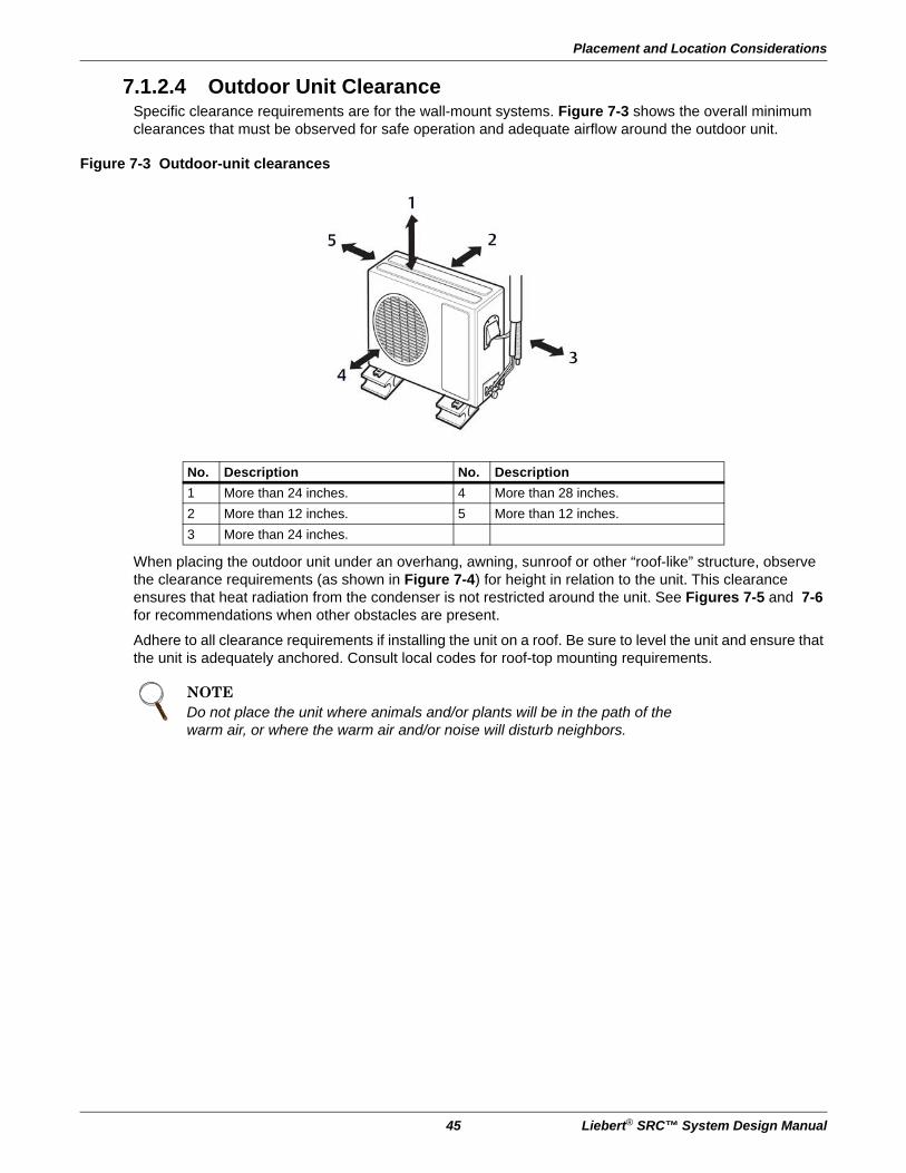
7.1.2.4 Outdoor Unit ClearanceSpecific clearance requirements are for the wall-mount systems. Figure 7-3 shows the overall minimum clearances that must be observed for safe operation and adequate airflow around the outdoor unit.
Figure 7-3 Outdoor-unit clearances
When placing the outdoor unit under an overhang, awning, sunroof or other “roof-like” structure, observe the clearance requirements (as shown in Figure 7-4) for height in relation to the unit. This clearance ensures that heat radiation from the condenser is not restricted around the unit. See Figures 7-5 and 7-6 for recommendations when other obstacles are present.
Adhere to all clearance requirements if installing the unit on a roof. Be sure to level the unit and ensure that the unit is adequately anchored. Consult local codes for roof-top mounting requirements.
No. Description No. Description
1 More than 24 inches. 4 More than 28 inches.
2 More than 12 inches. 5 More than 12 inches.
3 More than 24 inches.
NOTEDo not place the unit where animals and/or plants will be in the path of the warm air, or where the warm air and/or noise will disturb neighbors.

Application Guidelines
Liebert® SRC™ System Design Manual 46
Figure 7-4 Outdoor-unit sunroof/awning clearances
Figure 7-5 Clearances when there are obstacles on both air-inlet and air-outlet sides
No. Description
1 More than 12 inches.
2 More than 24 inches.
3 More than 28 inches.
No. Description
1 More than 28 inches.
2 More than 12 inches.
NOTEIn Figures 7-5 and 7-6, the obstacle on the outlet side is lower than the outdoor unit.

Placement and Location Considerations
47 Liebert® SRC™ System Design Manual
Figure 7-6 Clearances when there are obstacles above and on both air-inlet and air-outlet sides
No. Description No. Description
1 More than 28 inches. 3 79 inches
2 24 inches 4 More than 12 inches.

Application Guidelines
Liebert® SRC™ System Design Manual 48
7.2 Refrigerant Piping Design
7.2.1 Device Connection LimitationsLiebert SRC systems consist of one outdoor unit and one indoor unit. One of the most critical elements of a system is the refrigerant piping. Table 7-1 lists pipe-length limits that must be followed in the design of an SRC system. Refer to Figure 7-7 for maximum length and elevation of piping.
Figure 7-7 System layout
Table 7-1 Refrigerant-piping system limitations
Pipe Length(ELF = Equivalent length of pipe in feet)
Longest total equivalent piping lengthSRC18 SRC24 SRC36
98.4 164.0 164.0
Shortest total equivalent piping length 9.8 9.8 9.8
Distance between fittings and indoor units or outdoor units >20 in. >20 in. >20 in.
Elevation(All elevation limitations are measured
in actual feet.)
If outdoor unit is above indoor unit. 49.2 98.4 98.4
If outdoor unit is below indoor unit. 49.2 98.4 98.4
Additional refrigerant needed (oz/ft) 0.22 0.38 0.38
No. Description No. Description
1 Indoor unit 3 Maximum length
2 Outdoor unit 4 Maximum elevation

Refrigerant Piping Design
49 Liebert® SRC™ System Design Manual
7.2.2 Selecting Field-supplied Copper TubingCopper is the only approved refrigerant-pipe material for use with the Liebert SRC, and Emerson recommends seamless phosphorous deoxidized ACR type copper pipe, hard-drawn rigid type “K” or “L,” or annealed-tempered, copper pipe.
• Drawn temper (rigid) ACR copper tubing is available in sizes 3/8 through 2-1/8 inches (ASTM B 280,clean, dry, and capped).
• Annealed temper (soft) ACR copper tubing is available in sizes 1/4 through 2-1/8 inches (ASTM B 280,clean, dry, and capped).
Copper Expansion and ContractionUnder normal operating conditions, the vapor pipe temperature of a Liebert SRC can vary as much as 280°F. With this large variance in pipe temperature, the designer must consider pipe expansion and contraction to avoid pipe and fitting fatigue failures.
NOTETube wall thickness should meet local code requirements and be approved for an operating pressure of 551 psi. If local code does not specify wall thickness, Emerson suggests using tube thickness per Table 7-2. When bending tubing, try to keep the number of bends to a minimum, and use the largest radii possible to reduce the equivalent length of installed pipe. Also, bending radii greater than 10 pipe diameters can minimize pressure drop. Be sure that no traps or sags are present when rolling-out soft copper-tubing coils.
Table 7-2 ACR copper-tubing material
Type Seamless phosphorous deoxidized
Class UNS C12200 DHP
Straight Lengths H58 temper
Coils O60 temper
Table 7-3 Linear thermal expansion of copper tubing, in inches
Pipe
Length1
Fluid Temperature, °F
35° 40° 45° 50° 55° 60° 65° 70° 75° 80° 85° 90° 95° 100° 105° 110° 115° 120° 125° 130°
10 0.04 0.04 0.05 0.06 0.06 0.07 0.08 0.08 0.09 0.09 0.10 0.10 0.11 0.11 0.11 0.12 0.13 0.14 0.15 0.15
20 0.08 0.08 0.10 0.12 0.13 0.14 0.15 0.16 0.17 0.18 0.19 0.20 0.21 0.22 0.22 0.23 0.26 0.28 0.29 0.30
30 0.12 0.12 0.15 0.18 0.20 0.21 0.23 0.24 0.26 0.27 0.29 0.30 0.32 0.33 0.32 0.35 0.39 0.42 0.44 0.45
40 0.16 0.16 0.20 0.24 0.26 0.28 0.30 0.32 0.34 0.36 0.38 0.40 0.42 0.44 0.43 0.46 0.52 0.56 0.58 0.60
50 0.20 0.20 0.25 0.30 0.33 0.35 0.38 0.40 0.43 0.45 0.48 0.50 0.53 0.55 0.54 0.58 0.65 0.70 0.73 0.75
60 0.24 0.24 0.30 0.36 0.39 0.42 0.45 0.48 0.51 0.54 0.57 0.60 0.63 0.66 0.65 0.69 0.78 0.84 0.87 0.90
1. Pipe length baseline temperature = 0°F. “Expansion of Carbon, Copper and Stainless Steel Pipe,”

Application Guidelines
Liebert® SRC™ System Design Manual 50
Figure 7-8 Coiled expansion loops and offsets
No. Description No. Description
1 Length (L) 1 Large tubing U-bend (greater than 3/4 in.)
2 Radii (R) 2 Loop
3 Small tubing U-bend (less than 3/4 in.)
Table 7-4 Radii of coiled expansion loops and developed lengths of expansion offsets
Anticipated Linear Expansion (LE)
(in.)
Nominal Tube Size (OD) in.
1/4 3/8 1/2 3/4
1/2R1 6 7 8 9
L2 38 44 50 59
1R1 9 10 11 13
L2 54 63 70 83
1-1/2R1 11 12 14 16
L2 66 77 86 101
2R1 12 14 16 19
L2 77 89 99 117
2-1/2R1 14 16 18 21
L2 86 99 111 131
3R1 15 17 19 23
L2 94 109 122 143
3-1/2R1 16 19 21 25
L2 102 117 131 155
4R1 17 20 22 26
L2 109 126 140 166

Refrigerant Piping Design
51 Liebert® SRC™ System Design Manual
7.2.3 Piping Installation and Layout Best Practices
7.2.3.1 Layout ProcedurePhysical pipe length—Actual length of straight segment(s) of pipe.
Equivalent pipe length—Actual length of pipe plus equivalent lengths of elbows, Y-branches and valves.
1. Draft a one-line diagram of the proposed piping system connecting the outdoor unit to heat-recovery and indoor units. Follow the pipe limitations listed in Table 7-1.
2. Calculate the physical length of each pipe segment and note it on the drawing.
3. Calculate the equivalent pipe length of each pipe segment.
7.2.3.2 Using ElbowsFiled-supplied elbows are allowed as long as they are designed for use with R410A refrigerant. The designer, however, should be cautious with the quantity and size of fittings used, and must account for the additional pressure losses in equivalent-pipe-length calculation.
The equivalent pipe length of each elbow must be added to each pipe segment, Table 7-5.
7.2.3.3 Field-provided Isolation Ball ValvesEmerson allows the installation of field-supplied ball valves with Schrader ports at each indoor unit. Full-port isolation ball valves with Schrader ports (positioned between valve and indoor unit) rated for use with R410A refrigerant should be used on both the liquid and vapor lines.
If valves are not installed and a single indoor unit must be removed or repaired, the entire system must be shut down and evacuated. Position valves with a minimum distance of 3 to 6 inches of pipe on either side of the valve, and placed between 6 and 12 inches from the run-out pipe to the upstream main pipe. If ball valves are installed closer that this to the indoor unit, a section of pipe becomes a dead zone where oil may accumulate when the valves are closed.
Table 7-5 Equivalent piping length for piping components
Component Size (in.)
Elbow (ft)1/4 3/8 1/2 5/8 3/4
0.5 0.6 0.7 0.8 1.2

Application Guidelines
Liebert® SRC™ System Design Manual 52
7.2.3.4 ObstaclesWhen an obstacle, such as an I-beam or concrete T, is in the path of the planned refrigerant-pipe run, it is best practice to route the pipe over the obstacle. If adequate space is not available to route the insulated pipe over the obstacle, then route the pipe under the obstacle. In either case, it is imperative that the length of the horizontal section of pipe above or below the obstacle be a minimum of 3-times the longest vertical rise (or fall) at either end of the segment, Figure 7-9.
Figure 7-9 Installing piping above and below an obstacle
7.2.3.5 In-line Refrigeration ComponentsComponents such as oil traps, solenoid valves, filter-dryers, sight glasses, tee fittings and other after-market accessories are not permitted on the refrigerant piping system between the outdoor unit and the indoor unit. Liebert SRC systems are provided with redundant systems that assure oil is properly returned to the compressor. Sight glasses and solenoid valves may cause vapor to form in the liquid stream. Over time, dryers may deteriorate and introduce debris into the system. The designer and installer should verify that the refrigerant-piping system is free of traps, sagging pipes, sight glasses, filter dryers, etc.
7.2.3.6 No Pipe Size SubstitutionsUse only the pipe size recommended by this manual. Using a different size is prohibited and may result in a system malfunction or failure to work at all.
No. Description
1 Above an obstacle
2 Below an obstacle

Refrigerant Piping Design
53 Liebert® SRC™ System Design Manual
7.2.3.7 Pipe Supports
Pipe supports should never touch the pipe wall. Insulate the pipe first because pipe supports must be install outside (around) the primary pipe-insulation jacket, Figure 7-10. Use Clevis hangers with shield between the hangers and insulation. Field-provided pipe supports should be designed to meet local codes. If allowed by code, use fiber straps or split-ring hangers suspended from the ceiling on all-thread rods (fiber straps or split-ring hangers may be used as long as they do not compress the pipe insulation). Place a second layer of insulation of the pipe-insulation jacket to prevent chafing and compression of the primary insulation withing the confines of the support-pipe clamp.
Figure 7-10 Pipe-hanger details
A properly-installed pipe system has sufficient supports to prevent pipes from sagging during the life of the system. As necessary, place supports closer for segments where potential sagging could occur. Maximum spacing of the pipe supports must meet local codes.
If local codes do not specify pipe-support spacing, support the pipes as follows:
• Maximum of 5 feet on center for straight segments of pipe up to 3/4-in. outside diameter.
• Maximum of 6 feet on center for pipe up to 1-in. outside diameter.
• Maximum of 8 feet on center for pipe up to 2-in. outside diameter.
Wherever the pipe changes direction, place pipe clamps within 12 inches on one side and within 12 to 19 inches of bend on the other side, as shown in Figure 7-11.
Figure 7-11 Typical pipe-support location for a change in pipe direction
NOTEA properly-installed pipe system should be adequately supported to avoid pipe sagging. Sagging pipes become oil traps that lead to equipment malfunction.
No. Description
1 Pipe clamps

Application Guidelines
Liebert® SRC™ System Design Manual 54
7.2.3.8 Pipe Sleeves at PenetrationsEmerson requires that all pipe penetrations through walls, floors, and pipes buried underground be properly-insulated and routed through an appropriate wall sleeve of sufficient size to prevent compression of refrigerant-pipe insulation and free movement of the pipe withing the sleeve, Figure 7-12.
Figure 7-12 Pipe sleeve options
No. Description No. Description
1 Inside wall (concealed) 9 Lagging
2 Outside wall 10 Caulk
3 Outside wall (exposed) 11 Band
4 Floor (fire-resistance) 12 Water-resistant layer
5 Roof pipe shaft 13 Sleeve with edge
6Area between fire-resistant insulation and boundary wall
14 Lagging
7 Sleeve 15 Mortar or other fire-resistant caulk
8 Insulation 16 Fire-resistant insulation
NOTEThe diameter of the penetrations must be determined by the pipe diameter plus the thickness of the insulation.

Refrigerant Piping Design
55 Liebert® SRC™ System Design Manual
7.2.3.9 Underground Refrigerant PipingRefrigerant pipe installed underground should be routed inside a vapor-tight protective sleeve to prevent deterioration of the insulation and water infiltration. Refrigerant pipe installed inside underground casing must be continuous without any joints. Underground refrigerant pipe must be located at a level below the frost line.
Figure 7-13 shows the arrangement of refrigerant pipe and cable(s) in a conduit. Table 7-6 shows conduit sizes for utility conduit.
Figure 7-13 Typical arrangement of pipe and cables in a utility conduit
No. Description No. Description
1 Vapor line 4 Pipe sleeve
2 Insulation material 5 Insulation material
3 Liquid line 6 Power/Communication cable
Table 7-6 Utility-conduit sizes
Liquid Pipe1
Vapor Pipe1
3/8 (1-1/82,3) 5/8 (2-1/82,4)
3/8 (1-1/8)3 4 4
1. OD pipe diameter in inches. Values in parentheses indicate OD of pipe with insulation jacket.
2. Diameter of pipe with insulation. Thickness of pipe insulation is typical. Actual required thickness may vary based on surrounding ambient conditions and should be calculated and specified by the design engineer.
3. Insulation thickness (value in parenthesis) = 3/8 inch.4. Insulation thickness (value in parenthesis) = 1 inch.
Table 7-7 Heat-pump unit refrigerant-pipe connections (All brazed type)
Model Liquid Conn., in. Vapor Conn., in.
SCR18, 24, 36 3/8 5/8

Application Guidelines
Liebert® SRC™ System Design Manual 56
7.2.3.9.1 Brazing Practices
All joints are brazed in the field. Refrigeration-system components contain very small capillary tubes, small orifices, electronic expansion valves, oil separators, and heat exchangers that can easily become blocked. Proper system operation depends on the installer using best practices and utmost care while assembling the piping system.
Figure 7-14 Refrigerant-pipe brazing
• While brazing, use a dry-nitrogen purge operating at a minimum pressure of 3 psig and maintain a steady flow.
• Before assembly, use dry nitrogen to blow clean all pipe sections.
• Use a tubing cutter, do not use a saw to cut pipe. De-burr and clean all cuts before assembly.
• Store pipe stock in a dry place. Keep pipe capped and clean.
• Use adapters to assemble different sizes of pipe.
• Do not use flux, soft solder, or anti-oxidant agents.
• Use a 15% silver phosphorous copper-brazing alloy to avoid overheating and produce good flow.
• Protect isolation valves, electronic expansion valves, and other heat-sensitive control components from excessive heat with a wet rag or a heat-barrier spray product.
7.2.3.10 Piping InsulationTo prevent heat loss/heat gain through the refrigerant piping, all refrigerant piping, including liquid lines and vapor lines, must be insulated separately. Insulation must be a minimum 1/2-in. thick, and the thickness may need to be increased based on ambient conditions and local codes. All refrigerant piping, including field-supplied isolation ball valves, service valves, and elbows must be completely insulated using closed-cell pipe insulation. All insulation joints must be glued with no air gaps. Insulation material must fit snugly against the refrigerations pipe with now space between it and the pipe. Insulation passing through pipe hangers, inside conduit, and/or sleeves must not be compressed. Protect insulation inside hangers and supports with a second layer. All pipe insulation exposed to direct sunlight and deterioration-producing elements must be properly protected with a PVC-aluminum vapor-barrier jacket, or placed in a weather-resistant enclosure such as a pipe rack with a top cover. The design engineer should perform calculations to determine if the factory-supplied insulation jackets have sufficient thickness to meet local codes and to void sweating at job-site conditions. Maximum refrigerant-pipe temperature is 227°F. Minimum refrigerant-pipe temperature is –4°F. Add additional insulation if necessary.
NOTEIt is imperative to keep the piping system free of contaminants and debris such as copper burrs, slag, or carbon dust during installation. Contaminants can result in mechanical failure of the system.
No. Description No. Description
1 Refrigerant piping 4 Pressure-reducing valve
2 Pipe to be brazed 5 Valve
3 Nitrogen 6 Taping

Electrical Connections
57 Liebert® SRC™ System Design Manual
7.2.3.11 ChargingEach outdoor unit is factory-charged (nameplate charge) for the evaporator as wells as a standard 25-ft line. Any time a line set is used longer than the standard 25-ft line-set length, the refrigerant charge must be adjusted.
You must adjust the charge based on how many feet of piping are added based on 0.22 or 0.38 oz of R410A per foot. The factory charge accommodates pipe lengths up to the standard length without requiring refrigerant removal.
Example: A 30-ft line set is used, 5.4 additional feet x 0.38 oz per foot = Add 2.05 oz of R410A.
7.3 Electrical Connections
7.3.1 Outdoor Electrical ConnectionThe general guidelines for the electrical and communication cables to the outdoor unit are the same for each system. However, the actual connections on the terminal block will differ. Refer to each figure for the model you are installing for the correct wiring of each terminal block.
Use a recognized circuit breaker between the power source and the unit. A disconnecting device to adequately disconnect all supply lines must be fitted.
Figure 7-15 shows an example of how a circuit breaker should be wired through the Liebert SRC system.
NOTEIf you are uncertain of the unit charge, reclaim, evacuate and weigh-in the correct charge using the unit nameplate (capacity) charge adjusting for line sets longer than 24.6 or 41 ft. This will prevent interruptions to unit function and possible damage.
Table 7-8 Refrigerant charge capacity and Additional refrigerant per foot
Model
Pipe sizeStandard Length, ft
Max. Elevation, ft
Max Length, ft
Min. Length, ft
Additional Refrigerant,
oz/ftVapor Liquid
All Models 5/8 3/8 24.6 49.2 98.4 9.8 0.38
! WARNINGArc flash and electric shock hazard. Can cause serious injury or death. Open all local and remote electric power disconnect switches, verify with a voltmeter that power is off and wear personal protective equipment per NFPA 70E before working within the electric control enclosure or making any electrical connections or disconnections.
• Follow all safety and warning information in this manual.
• Verify that a circuit breaker or some other emergency-power cutoff device is in place before any power wiring is done to the system.
• Never touch any power lines or live cables before power is cut-off to the system.
• Familiarize yourself with the location of the circuit breaker.

Application Guidelines
Liebert® SRC™ System Design Manual 58
Figure 7-15 Circuit breaker wiring
Figure 7-16 Outdoor-unit terminal-block connections
No. Description
1 Main power source
2 Air conditioner
3Circuit breakerUse a circuit breaker or time-delay fuse.
1
4
32
1
5
6
7
8
1(L1) 2(L2)
GN/YL BR
1(L1) 2(L2) 3
BL
BR BRBL BL RDGN/YL
GN/YL


Technical Support / Service Monitoring800-222-5877Outside North America: +00800 1155 4499
Single-Phase UPS & Server Cabinets 800-222-5877Outside North America: +00800 1155 4499 Three-Phase UPS & Power Systems 800-543-2378Outside North America: 614-841-6598 Thermal Management Systems800-543-2778Outside the United States: 614-888-0246
LocationsUnited States
1050 Dearborn DriveP.O. Box 29186
Columbus, OH 43229
EuropeVia Leonardo Da Vinci 8
Zona Industriale Tognana35028 Piove Di Sacco (PD) Italy
+39 049 9719 111Fax: +39 049 5841 257
Asia7/F, Dah Sing Financial Centre
108 Gloucester Road, WanchaiHong Kong
852 2572220Fax: 852 28029250
While every precaution has been taken to ensure the accuracy and completeness of this literature, Liebert Corporation assumes no responsibility and disclaimsall liability for damages resulting from use of this information or for any errors or omissions.© 2016 Liebert CorporationAll rights reserved throughout the world. Specifications subject to changewithout notice.® Liebert is a registered trademark of Liebert Corporation. All names referred to are trademarks or registered trademarks of their respective owners.
Emerson Network Power
SL-11060_REV1_10-16
590-1317-501B