Embed Size (px)
Citation preview

Precision CoolingFor Business-Critical Continuity™
Liebert XDK™ Rack Enclosure With Integrated Water-Based CoolingUser Manual–17kW
DISCONTINUED PRODUCT
IMPORTANT SAFETY INSTRUCTIONS
SAVE THESE INSTRUCTIONSLiebert engineers will provide comprehensive support on how to install the XDK.
Extensive material, function and quality checks ensure that you fully benefit from product functions and a long service life. Nevertheless, this product can produce hazards if it is used incorrectly by untrained personnel or is not used for the correct purpose.
Read these operating instructions carefully before commissioning the XDK.
The electrical equipment complies with the applicable VDE and accident prevention regulations. Haz-ardous voltages (higher than 50 VAC or higher than 100 VDC) are present:
• inside the electric box in the unit's housing• behind the fan cover on the outside of the rear door
Shut down the unit immediately if there are problems with electrical input or cold water supply.
Operate the XDK correctly within the stipulated ratings and with approved equipment.
During all work on and with the unit, observe:
• All applicable regulations (e. g., VDE regulations and other applicable national regulations)• All applicable accident prevention instructions (BGV)• All applicable laws on environmental protection
Operate the XDK only if it is in proper working condition. If a malfunction or fault occurs, you must shut down the unit immediately and notify the responsible facility official or employee.
Resume operating the unit only after the malfunction or fault has been rectified and the XDK’s func-tion has been re-established.
! WARNINGRisk of electric shock. Can cause injury or death.Disconnect all local and remote electric power supplies before working within.Only qualified personnel may perform repair, maintenance, and cleaning operations.
NOTECleaning and servicing must be performed by qualified personnel. To ensure that the unit remains safe to use and has a long service life, observe the maintenance and cleaning intervals.
! CAUTIONRisk of contact with hot surfaces. Can cause burn injury.Fans, power supplies, PC boards, and other components become extremely hot during unit operation. Allow sufficient time for them to cool before working within the unit.Use extreme caution and wear protective gloves and arm protection when working on or near hot components.

i
TABLE OF CONTENTS
IMPORTANT SAFETY INSTRUCTIONS . . . . . . . . . . . . . . . . . . . . . . . . . . . . . . . . INSIDE FRONT COVER
1.0 INTRODUCTION . . . . . . . . . . . . . . . . . . . . . . . . . . . . . . . . . . . . . . . . . . . . . . . . . . . . . . . . . .12.0 OPERATING CONDITIONS . . . . . . . . . . . . . . . . . . . . . . . . . . . . . . . . . . . . . . . . . . . . . . . . . .22.1 Proper Application . . . . . . . . . . . . . . . . . . . . . . . . . . . . . . . . . . . . . . . . . . . . . . . . . . . . . . . . . . . 2
3.0 DESCRIPTION . . . . . . . . . . . . . . . . . . . . . . . . . . . . . . . . . . . . . . . . . . . . . . . . . . . . . . . . . . .33.1 General function . . . . . . . . . . . . . . . . . . . . . . . . . . . . . . . . . . . . . . . . . . . . . . . . . . . . . . . . . . . . . 3
3.2 Principle of Cooling Operation. . . . . . . . . . . . . . . . . . . . . . . . . . . . . . . . . . . . . . . . . . . . . . . . . . 4
3.2.1 Data Overview—XDK . . . . . . . . . . . . . . . . . . . . . . . . . . . . . . . . . . . . . . . . . . . . . . . . . . . . . . . . . 5
3.3 Control. . . . . . . . . . . . . . . . . . . . . . . . . . . . . . . . . . . . . . . . . . . . . . . . . . . . . . . . . . . . . . . . . . . . . 6
3.4 Automatic Door Opening . . . . . . . . . . . . . . . . . . . . . . . . . . . . . . . . . . . . . . . . . . . . . . . . . . . . . . 6
3.4.1 Function . . . . . . . . . . . . . . . . . . . . . . . . . . . . . . . . . . . . . . . . . . . . . . . . . . . . . . . . . . . . . . . . . . . . 73.4.2 Initial Commissioning: . . . . . . . . . . . . . . . . . . . . . . . . . . . . . . . . . . . . . . . . . . . . . . . . . . . . . . . . . 73.4.3 Manual Closing. . . . . . . . . . . . . . . . . . . . . . . . . . . . . . . . . . . . . . . . . . . . . . . . . . . . . . . . . . . . . . . 83.4.4 Manual Opening . . . . . . . . . . . . . . . . . . . . . . . . . . . . . . . . . . . . . . . . . . . . . . . . . . . . . . . . . . . . . . 8
4.0 EQUIPMENT INSPECTION, HANDLING AND STORAGE. . . . . . . . . . . . . . . . . . . . . . . . . . . . . . .94.1 Packaging Material . . . . . . . . . . . . . . . . . . . . . . . . . . . . . . . . . . . . . . . . . . . . . . . . . . . . . . . . . . 9
4.2 Handling . . . . . . . . . . . . . . . . . . . . . . . . . . . . . . . . . . . . . . . . . . . . . . . . . . . . . . . . . . . . . . . . . . . 9
4.3 Storage . . . . . . . . . . . . . . . . . . . . . . . . . . . . . . . . . . . . . . . . . . . . . . . . . . . . . . . . . . . . . . . . . . . 10
4.4 Returning the Unit in Case of Damage. . . . . . . . . . . . . . . . . . . . . . . . . . . . . . . . . . . . . . . . . . 10
5.0 INSTALLATION AND COMMISSIONING . . . . . . . . . . . . . . . . . . . . . . . . . . . . . . . . . . . . . . . . . 115.1 Preparation for Installation . . . . . . . . . . . . . . . . . . . . . . . . . . . . . . . . . . . . . . . . . . . . . . . . . . . 11
5.2 Positioning the XDK. . . . . . . . . . . . . . . . . . . . . . . . . . . . . . . . . . . . . . . . . . . . . . . . . . . . . . . . . 11
5.2.1 Remove Recirculation Air Duct Transport Lock . . . . . . . . . . . . . . . . . . . . . . . . . . . . . . . . . . . 11
5.3 Water Connection . . . . . . . . . . . . . . . . . . . . . . . . . . . . . . . . . . . . . . . . . . . . . . . . . . . . . . . . . . . 12
5.3.1 Preparing Heat Exchanger for Initial Commissioning. . . . . . . . . . . . . . . . . . . . . . . . . . . . . . . 12
5.4 Condensed Water Connection . . . . . . . . . . . . . . . . . . . . . . . . . . . . . . . . . . . . . . . . . . . . . . . . . 14
5.5 Electrical Connection . . . . . . . . . . . . . . . . . . . . . . . . . . . . . . . . . . . . . . . . . . . . . . . . . . . . . . . . 15
5.6 Sealing the Cabinet . . . . . . . . . . . . . . . . . . . . . . . . . . . . . . . . . . . . . . . . . . . . . . . . . . . . . . . . . 15
6.0 SERVICING AND MAINTENANCE . . . . . . . . . . . . . . . . . . . . . . . . . . . . . . . . . . . . . . . . . . . . .166.1 General Inspection on Fans—Annual . . . . . . . . . . . . . . . . . . . . . . . . . . . . . . . . . . . . . . . . . . . 16
6.1.1 Fan Replacement . . . . . . . . . . . . . . . . . . . . . . . . . . . . . . . . . . . . . . . . . . . . . . . . . . . . . . . . . . . . 16
6.2 Inspect the Heat Exchanger—Annual . . . . . . . . . . . . . . . . . . . . . . . . . . . . . . . . . . . . . . . . . . 17
6.3 Replacing the Heat Exchanger . . . . . . . . . . . . . . . . . . . . . . . . . . . . . . . . . . . . . . . . . . . . . . . . 18
7.0 DISMANTLING AND DISPOSAL . . . . . . . . . . . . . . . . . . . . . . . . . . . . . . . . . . . . . . . . . . . . . .198.0 WATER PURITY REQUIREMENTS . . . . . . . . . . . . . . . . . . . . . . . . . . . . . . . . . . . . . . . . . . . .208.1 Unit Installation Checklist . . . . . . . . . . . . . . . . . . . . . . . . . . . . . . . . . . . . . . . . . . . . . . . . . . . 21
8.2 Commissioning Certificate. . . . . . . . . . . . . . . . . . . . . . . . . . . . . . . . . . . . . . . . . . . . . . . . . . . . 22

ii
FIGURESFigure 1 Cooling airflow, top view . . . . . . . . . . . . . . . . . . . . . . . . . . . . . . . . . . . . . . . . . . . . . . . . . . . . . . . . . . 3Figure 2 Cooling airflow, side view . . . . . . . . . . . . . . . . . . . . . . . . . . . . . . . . . . . . . . . . . . . . . . . . . . . . . . . . . . 4Figure 3 XDK door and automatic opening mechanism . . . . . . . . . . . . . . . . . . . . . . . . . . . . . . . . . . . . . . . . . 6Figure 4 Door locking mechanisms, opening switch . . . . . . . . . . . . . . . . . . . . . . . . . . . . . . . . . . . . . . . . . . . . 7Figure 5 Remove the transport lock screws . . . . . . . . . . . . . . . . . . . . . . . . . . . . . . . . . . . . . . . . . . . . . . . . . . 11Figure 6 Heat exchanger access . . . . . . . . . . . . . . . . . . . . . . . . . . . . . . . . . . . . . . . . . . . . . . . . . . . . . . . . . . . 12Figure 7 Control valve . . . . . . . . . . . . . . . . . . . . . . . . . . . . . . . . . . . . . . . . . . . . . . . . . . . . . . . . . . . . . . . . . . . 12Figure 8 Heat exchanger . . . . . . . . . . . . . . . . . . . . . . . . . . . . . . . . . . . . . . . . . . . . . . . . . . . . . . . . . . . . . . . . . 13Figure 9 Heat exchanger connection. . . . . . . . . . . . . . . . . . . . . . . . . . . . . . . . . . . . . . . . . . . . . . . . . . . . . . . . 13Figure 10 Bottom plate with cutouts . . . . . . . . . . . . . . . . . . . . . . . . . . . . . . . . . . . . . . . . . . . . . . . . . . . . . . . . 14Figure 11 Replacing a fan . . . . . . . . . . . . . . . . . . . . . . . . . . . . . . . . . . . . . . . . . . . . . . . . . . . . . . . . . . . . . . . . . 16Figure 12 Heat exchanger replacement . . . . . . . . . . . . . . . . . . . . . . . . . . . . . . . . . . . . . . . . . . . . . . . . . . . . . . 18
TABLESTable 1 General operating data . . . . . . . . . . . . . . . . . . . . . . . . . . . . . . . . . . . . . . . . . . . . . . . . . . . . . . . . . . . . 2Table 2 Technical data . . . . . . . . . . . . . . . . . . . . . . . . . . . . . . . . . . . . . . . . . . . . . . . . . . . . . . . . . . . . . . . . . . . 5Table 3 XDK general data . . . . . . . . . . . . . . . . . . . . . . . . . . . . . . . . . . . . . . . . . . . . . . . . . . . . . . . . . . . . . . . . 5Table 4 Prevalent impurities and removal methods . . . . . . . . . . . . . . . . . . . . . . . . . . . . . . . . . . . . . . . . . . 20Table 5 Suggested hydrologic levels . . . . . . . . . . . . . . . . . . . . . . . . . . . . . . . . . . . . . . . . . . . . . . . . . . . . . . . 20Table 6 XDK – Commissioning certificate . . . . . . . . . . . . . . . . . . . . . . . . . . . . . . . . . . . . . . . . . . . . . . . . . . 22Table 7 Nominal values at setup site . . . . . . . . . . . . . . . . . . . . . . . . . . . . . . . . . . . . . . . . . . . . . . . . . . . . . . 22Table 8 Type of cabinet . . . . . . . . . . . . . . . . . . . . . . . . . . . . . . . . . . . . . . . . . . . . . . . . . . . . . . . . . . . . . . . . . 23Table 9 Control of status . . . . . . . . . . . . . . . . . . . . . . . . . . . . . . . . . . . . . . . . . . . . . . . . . . . . . . . . . . . . . . . . 23Table 10 Cold water facility on site . . . . . . . . . . . . . . . . . . . . . . . . . . . . . . . . . . . . . . . . . . . . . . . . . . . . . . . . . 24Table 11 Electrical data / documents . . . . . . . . . . . . . . . . . . . . . . . . . . . . . . . . . . . . . . . . . . . . . . . . . . . . . . . 24Table 12 Function check . . . . . . . . . . . . . . . . . . . . . . . . . . . . . . . . . . . . . . . . . . . . . . . . . . . . . . . . . . . . . . . . . 24

Introduction
1
1.0 INTRODUCTION
The Liebert XDK provides the dissipation of heat loads up to 17kW.
The server rack is closed to the installation area, that means no heat load will dissipate to the envi-ronment. (see also chapter 2.) The cooling is provided by a closed cooling system via an air-to-water heat exchanger. The cooling capacity adapts to the heat load.
19" (483mm) rails are designed for components as well as rails and shelves.
Cable entry is possible from the bottom and from the top.

Operating Conditions
2
2.0 OPERATING CONDITIONS
2.1 Proper ApplicationThe XDK is a water-cooled enclosure and is intended for removing heat from electronic equipment inside the cabinet. The cooling system in the cabinet is thermally independent of the room air. Water is used to cool equipment installed in the XDK. No additional cooling of the server room is required.
NOTEUnder certain conditions, a small amount of heat, (approximately 0.5kW), can escape into the room.
! CAUTIONRisk of improper operation. Can cause equipment damage. For reliable function of the XDK, cold water must be available in the correct amount, and at the correct temperature and pressure. Observe water quality specified in VGB-R 455 P. (see 8.0 - Water Purity Requirements ).
Table 1 General operating data
Ambient temperature 50°F to 95°F (10°C to 35°C)(other temperatures upon request)
Absolute humidity in the installation location 8g H2O/ kg air maximum
Water temperature, supply 54°F (12°C); other temperatures upon request
Water temperature, return 64°F (18°C); other temperatures upon request
Water connection from below
Condensed water connection from below
Nominal voltage 200V to 264V (50Hz and 60 Hz)
Maximum operating pressure 145 PSI (10 bar)

Description
3
3.0 DESCRIPTION
3.1 General functionThe modular design facilitates the installation of 19-inch-wide equipment of varying depth.
Heat produced by equipment in the cabinet, such as servers, is removed by the cold water system integrated into the server cabinet. The cooling system is isolated from the server area, protecting the sensitive equipment from water damage.
The cooling system comprises a high-performance air/water heat exchanger, fans with fan control unit, fan-speed according to heat load.
The air circuit is closed such that no heat is emitted to the environment.
Figure 1 Cooling airflow, top view
! CAUTIONRisk of improper operation. Can cause equipment damage.The XDK works only if cold server feed air and heated server outlet air are fully separated. Height units not in use must be sealed with blanking panels.
Server
Cold
AirSeparation
WarmWarm
Warm Warm
Air Duct
ColdFront

Description
4
3.2 Principle of Cooling OperationFigure 2 Cooling airflow, side view
Air that has been heated by the servers to 95°F (35°C), for example, is circulated to a specially designed air/water heat exchanger by high-performance fans. The heated air is cooled to 68-77°F (20-25°C) and fed to the front of the server.
The server fans can draw in the air and feed it over internal components.
Cold water is provided by a separate Liebert XD Pumping unit.
A condensate tray with a 5/8" outlet is below the heat exchanger.
NOTEIf the rear door (with fans) is opened, the front door must be opened. If the front door is opened, it is not necessary to open the rear door.
19" Equipment
Air / WaterHeat Exchanger
Cold Water Supply
Side of XDK
Rearof XDK
Front of XDK
Fan Bank

Description
5
3.2.1 Data Overview—XDK
Table 2 Technical dataHousing material Aluminium sheet, sheet steel, galvanized and coated
Operating Temperature range 50°F to 95°F (10°C to 35°C)
Abs. atmospheric humidity 8g / kg maximum
Temperature difference across server approx. 15K
Noise level 55 dB(A) sound pressure at a distance of 3 ft. (1m)
Useful load 2204 lb (1000kg)
Cold WaterCooling capacity 17kW
Supply temperature 54°F (12°C) (other temperatures upon consultation)
Return temperature 64°F to 72°F (18°C to 22°C) (other temperatures upon consultation)
Max. operating pressure 145 PSI (10 bar)
Water supply connection 1"
Table 3 XDK general dataNominal Cooling Capacity 17kW @ 54°F (12°C) EFT
Height, in (mm) 86.6 (2200)
Width, in (mm) 31.5 (800)
Depth, in (mm) 47 (1200)
Usable Height for ElectronicEquipment 40 U
Maximum ElectronicEquipment Depth, in (mm) 29 (740)
Electronic EquipmentAir Temperature, In/Out, °F (°C) 68/98 (20/37
Weight, Empty, lb (kg) 683 (310)
Maximum Weight, Filled 2,800 (1310)
Maximum OperatingWater Pressure, psi (bar) 145 (10)
Water Flow Rate, GPM (m3/h) 10.7 (2.44)
Water Pressure Drop, psi (bar) 10 (0.7)
Water Connections, in 1
Maximum Air Flow, CFM ( m3/h) 1800 (3,100)
Sound Pressure Level 55 dB(A) at 3 ft (1m)
Input Voltage 200-264 V, 1 ph, 50/60 Hz
Maximum Power Draw 1400W
Options Leveling Feet or Casters

Description
6
3.3 ControlThe server cabinet temperature is controlled by the fan control board
A temperature sensor continuously measures the temperature of the server cabinet (server feed air). The air circulation flow rate is controlled by the fan speed according to the current thermal load.
At temperatures lower than 70°F (21°C) fans rotate at 75% of maximum speed.
Between 68°F and 73°F (20 and 23°C), speed increases proportionally to the temperature up to 96% of maximum speed.
The failure of the temperature sensor set the fans to maximum speed.
The water flow rate is controlled by a three-way valve depending on thermal load. In case of failure, the valve opens and the all the chilled water flows through the heat exchanger.
From 61°F to 66°F (16°C to 19°C), the three-way valve controls the water flow rate from 0% to 100% of the nominal flow rate.
The programming of the control is factory-set and protected with a password.
The failure of the temperature sensor or one of the fans will set off an alarm using a potential free contact.
The outgoing alarms with potential free contact are:
• sensor error• fan malfunction• high-temperature / low-temperature
The fans are automatically shut down if the server cabinet rear door is opened.
3.4 Automatic Door OpeningFigure 3 XDK door and automatic opening mechanism
Upper magnet and retaining plate
Gas pressure spring

Description
7
3.4.1 FunctionFront and rear door are kept closed with two electromagnets. The door will be pushed open smoothly by a gas pressure spring if power to the electromagnets fails.
If the doors are opened, the thermal load can escape into the room, preventing the servers from over-heating.
The inflow of air with water droplets can also be prevented (Door opening due to humidity alarm). When the rear door is opened, the fans shut down automatically.
Figure 4 Door locking mechanisms, opening switch
3.4.2 Initial Commissioning:___ 1. Loosen the upper and lower transport lock screw
___ 2. Connect inlet power to the power supply (See 3.4.3 - Manual Closing.)
NOTEIf the power supply fails during initial commissioning, the front door opens automatically. If the transport lock screws are reinstalled, both transport lock screws must be reinserted or the door could be damaged
Upper and lowertransport-lock screw Door opening switch
with LED (green)

Description
8
3.4.3 Manual Closing1. Press LED switch for electromagnet activation2. The LED lights up3. Push door evenly shut. Both magnetic locks must latch.
3.4.4 Manual Opening1. Press LED switch - green LED doesn’t light2. Rack door opens itself

Equipment Inspection, Handling And Storage
9
4.0 EQUIPMENT INSPECTION, HANDLING AND STORAGE
Upon arrival of the unit, and before unpacking, verify that the labeled equipment matches the bill of lading. Inspect all items for damage, either visible or concealed. Damage should be immediately reported to the carrier and a damage claim filed with a copy sent to your local sales representative.
4.1 Packaging MaterialAll material used to package this unit is recyclable. Please save for future use or dispose of the material appropriately.
SAFETY INFORMATION
4.2 HandlingWhen possible, transport the unit using a forklift or pallet jack. Otherwise use a crane with belts or cables.
• When using a forklift or pallet jack, make sure the forks (if adjustable) are spread to the widest allowable distance that will fit under the skid.
• Ensure that the fork length is suitable for the unit length.• When using a forklift while moving the packaged XDK, do not lift it higher than 6" (152mm).• If circumstances require the XDK to be lifted higher than 6" (152mm), great care must be exer-
cised. Personnel not involved in moving the unit must be at least 20' (5m) from the lift point of the unit.
• Belts or cables must be used when the XDK is moved with a crane.• The XDK’s net weight is 749 lb. (340 kg).• Avoid twisting the housing or other damage during handling.• Ensure that the XDK’s doors are closed prior to lifting.• Do not stand under an XDK while it is suspended.• Hooks used to attach to the unit must be of appropriate tensile strength.• The XDK must not be lifted at an angle.
! WARNINGRisk of top-heavy unit falling over. Improper handling can cause equipment damage, injury or death! Read all of the following instructions before attempting to move, lift, remove packaging from or preparing unit for installation.
! WARNINGRisk of sharp edges, splinters and exposed fasteners. Can cause personal injury. Only properly trained personnel wearing appropriate safety headgear, gloves, shoes and glasses should attempt to move, lift, remove packaging from or prepare unit for installation.
! CAUTIONRisk of overhead interference. Can cause unit and/or structure damage.Refer to the installation plans prior to moving the unit to verify clearances.
! CAUTIONRisk of damage from fork lift! Improper handling with the forklift can cause exterior and/or underside damage! Keep tines of the fork lift level and at a height suitable to fit below the skid.
R

Equipment Inspection, Handling And Storage
10
4.3 Storage• If the XDK’s packaging has been removed, cover it with tarpaulins to protect against particulates,
such as sand and dust, and from moisture.• Keep storage temperature between -22°F and 104°F (-30°C and +40°C).• The heat exchanger must be completely drained to prevent the risk of freezing damage.• When stored for more than 12 months, turn fans by hand to check the fan bearings prior to instal-
lation.
4.4 Returning the Unit in Case of DamageIf the XDK is not returned in its original packaging, the packaging used for return must comply with the following:
• There must be at least 1-3/16" (30mm) space between the unit and the packaging.• Footprint of the skid shall extend at least 2-1/2" (64mm) from the perimeter of the unit.• The XDK must be attached to the skid using original metal brackets or steel banding.
If steel banding is used to hold unit to the skid, place reinforced protective material between the banding and the XDK.
• Ensure proper shipping information is affixed to the exterior of the packaging.

Installation and Commissioning
11
5.0 INSTALLATION AND COMMISSIONING
5.1 Preparation for Installation
To achieve good air circulation, ensure that there is no packaging material or other equipment that could hinder or prevent air circulation in the area of the equipment, in the area of the heat exchanger, in the air inlet or in the air outlet.
5.2 Positioning the XDKAfter positioning, the XDK’s feet must be adjusted to make the cabinet vertical. When positioned the doors must close easily.
5.2.1 Remove Recirculation Air Duct Transport Lock The Liebert XDK is shipped without the gas pressure springs for the front and rear automatic door openers installed. The springs should be installed according to separate instructions before the Lie-bert XDK is connected and turned on.
After positioning, remove the transport lock screws at the sides of the recirculation air duct (see Figure 5).
The recirculation air duct may be pulled out to remove items that fall into the heat exchanger tray.
Figure 5 Remove the transport lock screws
! CAUTIONRisk of improper installation. Can cause equipment damage.Before installing the unit, a number of points must be checked for safety and to ensure the correct function of the server cabinet. Take care when performing these checks to ensure that the unit functions correctly.
! CAUTIONRisk of improper installation. Can cause equipment damage.The XDK must be installed on a level surface. For this reason, check the horizontal alignment with a spirit level prior to starting installation. The floor must be able to support a rack load of 307 lb/ft² (1500 kg/m²) (with installed equipment per XDK).
Remove both screws
Installation and Commissioning
12
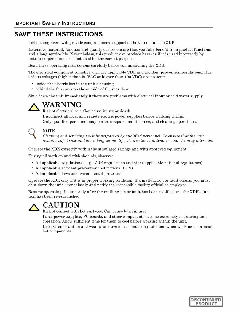
5.3 Water ConnectionThe heat exchanger can be pulled out for servicing
Water pipes should be connected so that the heat exchanger can be pulled out when the connection is undone. If the heat exchanger is connected to the water circuit using threaded fittings, the pipe fitting must be supported on tightening.
Before commissioning the server cabinet, the pipe connections should be checked for leaks according to local codes.
5.3.1 Preparing Heat Exchanger for Initial CommissioningCheck the mechanical installation and the supply pipe connection.
Figure 6 Heat exchanger access
1. Carefully bleed heat exchanger when filling the system.2. Open the air bleed valve until the water coming out has no bubbles.3. Close this valve after bleeding.
Figure 7 Control valve
4. If necessary, retighten threaded fittings.5. After an extended period without use, and particularly in case of risk of freezing temperatures,
the heat exchanger and the supply pipe must be drained of all fluid.6. Drain completely by blowing out with compressed air and remove all bleed and drain plugs.
Remove this air ductfor bleeding, draining the heat exchanger andchecking the valve
Water supplyDrain valve
Air bleed valve
Water return

Installation and Commissioning
13
Figure 8 Heat exchanger
Figure 9 Heat exchanger connection
Liebert recommends insulating the cold water pipes with waterproof insulation to prevent condensa-tion and losses.
9-7/8"(150mm)
2"(50mm)
2"(50mm)
33-7/16"(850mm)
27-3/8"(695mm)
Space for
Cabling
Top View
Water supply
Water return

Installation and Commissioning
14
Figure 10 Bottom plate with cutouts
Cable and pipe openings must be sealed air-tight on completion of work.
5.4 Condensed Water ConnectionIf the XDK is operated below dew point, condensed water may occur. As standard there is a water con-nection, 5/8" diameter, in the condensed water tray for drainage.
Preparations for Connecting
When connecting to the condensate tray, ensure that the condensed water pipe is connected to a self-filling siphon with return protection and that the condensate drain is properly sloped.
The height of the siphon must be designed for an underpressure or overpressure of 0.11psi (800 Pa) so that air is not drawn into or blown out of the waste pipe.
Front
Condensed Water Cutouts
Network Cable Entry
Sealed Cable CutoutRear
Cutout for Water Pipes
Step 1):Remove the air duct
Step 2):Remove the cap
Step 3.) Connect thenipple with a drain hose 5/8"
Condensate connection
Step 4.) Move and snap the nipple with hose into the hole

Installation and Commissioning
15
The condensate drain is not pressurized; a condensate pump can be used.
5.5 Electrical ConnectionThe wiring diagram is enclosed in the unit.
As soon as all preparations for installation have been made, you can start electrical installation.
Check whether voltage and frequency at installation site as well as fuse ratings match the specifica-tions on the rating plate.
To connect the unit to the power supply:
1. Shut down the server cabinet.2. See the wiring diagram for information on the connections to be made.3. Connect the supply cable in the computer room.4. Check the secure connection of the earth wire.
To return the server cabinet to operation, switch on the fuse-protected power supply.
5.6 Sealing the CabinetTo ensure the optimal cooling function the cabinet must be sealed:
• Pipe entrances should be cut into the foam and properly closed with a extra foam if required.• Cable entrances should be closed with the pivoting plate and foamed material.• Air flows on the warm and cold sides of the cabinet must be separated from each other.
! WARNINGRisk of electric shock. Can cause injury or death.Disconnect all local and remote electric power supplies before working within. Prior to beginning installation, shut down the server cabinet, disconnect it and secure it against unauthorized startup.
! WARNINGRisk of electric shock. Can cause injury or death.Disconnect all local and remote electric power supplies before working within.The XDK unit must be connected by a licensed and qualified electrician only. Ensure that the server cabinet is electrically isolated for the duration of the connection operation and is secured against unauthorized startup
NOTEThe unit's fans will rotate clockwise.

Servicing and Maintenance
16
6.0 SERVICING AND MAINTENANCE
6.1 General Inspection on Fans—Annual• Check for unusual bearing noises. (Check for excessive bearing play.)
6.1.1 Fan ReplacementThe expected service life is approximately 40,000 operating hours at a temperature of 40°C (104°F).
1. Remove the housing cover from the unit (with earth cable).2. Determine which fan has failed.3. Check the surface temperature of the fan and switch off the circuit breaker.4. Disconnect supply cable at the fan terminal block.5. Loosen the four fastening nuts for the fan to be replaced.6. Remove the failed fan.
Figure 11 Replacing a fan
! WARNINGRisk of high speed rotating fan blades. Can cause serious injury.Disconnect all local and remote electric powers supplies and assure that fan blades have stopped rotating before working within the unit.
! WARNINGRisk of electric shock. Can cause injury or death.Disconnect all local and remote electric power supplies before working within the unit.
! CAUTIONRisk of explosive discharge of water under pressure. Can cause injury or equipment damage.Shut off the water supply and relieve pressure before working with piping.
NOTEService and maintenance work must be performed only by properly trained personnel and in accordance with applicable regulations as well as with manufacturers’ specifications.
NOTEUse only original spare parts that have been tested and approved by the manufacturer. If necessary, request a comprehensive spare parts list from the manufacturer. For cleaning, use commercially available cleaning agents only. Follow the stipulated safety measures and do not use any tools that may cause scratching or tools for scraping (surfaces will be irreversibly damaged).
Step 3:Disconnect supply cable at the fanterminalblock
Step 4: Undo the fourfasteningnuts
One of four fastening nuts
Slot toinsertwrench to removenut
Servicing and Maintenance
17
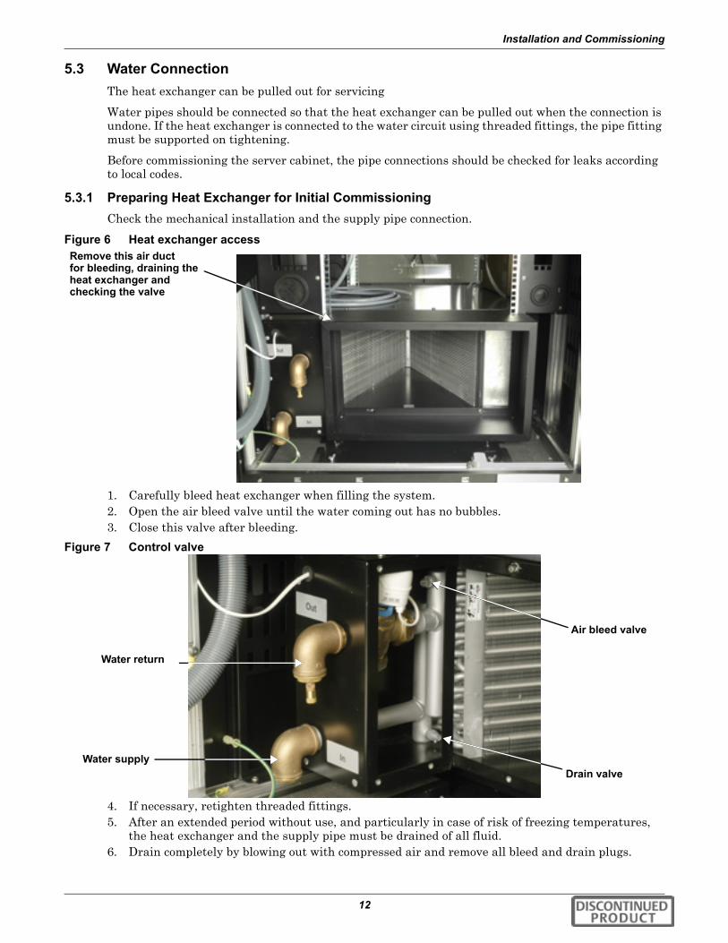
Reinstall the fan by reversing the steps to remove the fan.
1. Tighten the fan fastening bolts.2. Connect the power supply cable to the fan.
3. Switch on the circuit breaker.4. Dispose of the old fans correctly.
6.2 Inspect the Heat Exchanger—AnnualThe efficiency of heat exchangers is sharply reduced by dirt and debris; retaining high efficiency requires regular cleaning. Use a vacuum cleaner, compressed air or a soft brush to clean the fins.
Do not bend the fins during cleaning—this will interfere with proper air flow through the unit.
• Check heat exchanger on air side for soiling, damage and corrosion.• Check feed and return for correct function.• If necessary clean the air side.• Regularly check odor trap (external) for correct function.• Heat exchanger can be pulled out for improved cleaning.• Regularly visually inspect the water circuit for leaks.
! WARNINGRisk of electric shock. Can cause injury or death.Reconnect the earth ground cable to the sheet metal panel to prevent a potentially hazardous open circuit in case of loose or disconnected electrical wiring or a fan motor short circuit.

Servicing and Maintenance
18
6.3 Replacing the Heat ExchangerFigure 12 Heat exchanger replacement
Reinstall the heat exchanger by reversing the reverse order of removal.
NOTERegularly check the condensed water drain and clean if necessary
Step 1: Lift the air duct off the flange to remove it.
Step 2:Removethe groundingcable
Step 5: Pullout the heat exchanger
Step 4: Remove screws
Step 3:Remove condensate connection

Dismantling and Disposal
19
7.0 DISMANTLING AND DISPOSAL
The XDK may be dismantled by qualified personnel only.
Disconnect the unit from the external water circuit by closing the shutoff valves and drain the unit’s water circuit.
Transport the unit as described in 4.0 - equipment Inspection, Handling And Storage, using a lifting device with sufficient load-bearing capacity.
Dispose of the air conditioner in accordance with the locally applicable disposal and safety instruc-tions. Liebert recommends using a specialist recycling organization.
All parts can be stripped down and consist of:
• aluminium, steel, brass, copper• labelled plastic parts• electronic parts
! WARNINGRisk of electric shock. Can cause injury or death.Disconnect all local and remote electric power supplies before working within the unit.

Water Purity Requirements
20
8.0 WATER PURITY REQUIREMENTS
To ensure the maximum service life of the air/water heat exchangers, water must comply with the VGB water regulations (VGB-R 455 P). The water used must be soft enough to prevent deposits, but it must not be so soft that heat exchanger corrosion occurs.
The following table contains the most important impurities and methods for removing them.
It is recommended to achieve the following hydrological data as far as possible:
Table 4 Prevalent impurities and removal methods
Water Impurity Method of RemovalMechanical pre-treatment (dp < 1 mm) Filtering the water
Excessive hardness Soften the water using ion exchange
Moderate content of mechanical impurities and hardness formers Addition of dispersing or stabilizing agents
Moderate content of chemical impurities Addition of passivation agents and inhibitors
Biological impurities (bacteria and algae) Addition of biocides
Table 5 Suggested hydrologic levelsHydrological Data Suggested
AmountUnits
pH values 7 - 8.5
Carbonate hardness >3 <8 °dH
Free carbon dioxide 8 - 15 mg/dm3
Bound carbon dioxide 8 - 15 mg/dm3
Aggressive carbon dioxide 0 mg/dm3
Sulfides < 10 mg/dm3
Oxygen < 50 mg/dm3
Chloride ions < 250 mg/dm3
Sulfate ions < 10 mg/dm3
Nitrates and nitrides < 7 mg/dm3
CSB < 5 mg/dm3
Ammonia < 5 mg/dm3
Iron < 0.2 mg/dm3
Manganese < 0.2 mg/dm3
Conductivity < 2200 μS/cm
Solid evaporation residue < 500 mg/dm3
Potassium permanganate consumption < 25 mg/dm3
Suspended matter < 3 mg/dm3
(Partial flow cleaning is recommended) > 3 < 15 mg/dm3
(Continuous cleaning) > 15 mg/dm3

Water Purity Requirements
21
8.1 Unit Installation Checklist___ 1. Check unit for damage on delivery
___ 2. Check for level floor
___ 3. Check maximum floor load
___ 4. XDK feet adjusted, if applicable
___ 5. XDK is level
___ 6. No remains of packaging in the XDK
___ 7. All installation tools removed
___ 8. Cable entries into the unit correct and air-tight
___ 9. Cable connections checked
___ 10. Cold water connection does not leak
___ 11. Pressure test performed
___ 12. Water circuit bled
___ 13. Water flow rate adjusted
___ 14. Condensed water pipe clear
___ 15. Water system odor trap in order
___ 16. Heat exchanger tray connected to condensed water pipe
___ 17. Fan function checked
___ 18. All front panels closed (separation of air flows)
Comments
Signature DateChecker

Water Purity Requirements
22
8.2 Commissioning Certificate
Nominal values kept
___ 1. Yes
___ 2. No
Table 6 XDK – Commissioning certificateGeneral DataClient/Setup Site
Client Name
Client Address
Contact Persons
Phone Number
Setup Site / Room Number
Table 7 Nominal values at setup siteAir Humidityat Setup Site % Relative Humidity
AmbientTemperature °C (°F)
Nominal Valuesat Setup SiteTemperature °F (°C)
50(10)
59(15)
64(18)
66(19)
68(20)
70(21)
72(22
73(23
75(24
77(25
79(26
81(27
82(28
86(30
95(35
Maximum RelativeHumidity % 100 76 62 58 55 52 48 46 43 40 38 36 34 30 23
Water Purity Requirements
23
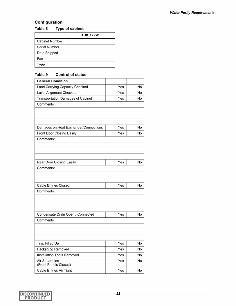
ConfigurationTable 8 Type of cabinet
XDK 17kW
Cabinet Number
Serial Number
Date Shipped
Fan
Type
Table 9 Control of statusGeneral ConditionLoad Carrying Capacity Checked Yes No
Level Alignment Checked Yes No
Transportation Damages of Cabinet Yes No
Comments
Damages on Heat Exchanger/Connections Yes No
Front Door Closing Easily Yes No
Comments:
Rear Door Closing Easily Yes No
Comments:
Cable Entries Closed Yes No
Comments
Condensate Drain Open / Connected Yes No
Comments
Trap Filled Up Yes No
Packaging Removed Yes No
Installation Tools Removed Yes No
Air Separation(Front Panels Closed)
Yes No
Cable Entries Air Tight Yes No

Water Purity Requirements
24
.
Table 10 Cold water facility on siteCold WaterXDK Connected ToWater Temperature Feed °C/°F Return
Water Pressure Feed PSI (Pa) Return PSI (Pa)
Water Differential Pressure Pa
Table 11 Electrical data / documentsWiring Scheme Attached Yes No
Comments
Cable Connections Checked: Yes No
Electrical Acceptance Certificate by Approved Staff
Yes No
Comments
Table 12 Function checkFunction of All Fans(Air Blowing Direction)
Yes No
Fans Shut Down When Rear Door is Opened
Yes No
Comments
Function Three Way Valve Yes No
Comments
Door Opens When ____ °F (°C) is Reached
Yes No
Comments

Water Purity Requirements
25
Commissioning performed by day to day operating.
Correctness of function check protocol certified by:
Malfunction Indicator Function Yes No
Comments
Condensate Occurrence at Heat Exchanger
Yes No
Comments
Pressure Test Water Circuit Yes
Water Flow Rate Adjusted Yes No
Flow Rate(Possible Only Externally)
GPM
Water Feed °F (°C)
Water Return °F (°C)
Air Temperature in the CabinetAt The Heat Exchanger Inlet °F (°C)
Air Temperature in the Cabinet At the Heat Exchanger Outlet °F (°C)
Approved Staff Date Signature
Client Date Signature
Table 12 Function check (continued)

Water Purity Requirements
26


Ensuring The High Availability0f Mission-Critical Data And Applications.
Emerson Network Power, the global leader in enabling business-criticalcontinuity, ensures network resiliency and adaptability througha family of technologies—including Liebert power and coolingtechnologies—that protect and support business-critical systems.Liebert solutions employ an adaptive architecture that respondsto changes in criticality, density and capacity. Enterprises benefitfrom greater IT system availability, operational flexibility andreduced capital equipment and operating costs.
While every precaution has been taken to ensure the accuracyand completeness of this literature, Liebert Corporation assumes noresponsibility and disclaims all liability for damages resulting from use ofthis information or for any errors or omissions.© 2007 Liebert CorporationAll rights reserved throughout the world. Specifications subject to changewithout notice.® Liebert and the Liebert logo are registered trademarks of LiebertCorporation. All names referred to are trademarksor registered trademarks of their respective owners.
Technical Support / ServiceWeb Site
www.liebert.comMonitoring
Outside the US: 614-841-6755Single-Phase UPS
Outside the US: 614-841-6755Three-Phase UPS
Environmental Systems800-543-2778
Outside the United States614-888-0246
LocationsUnited States
1050 Dearborn DriveP.O. Box 29186
Columbus, OH 43229Europe
Via Leonardo Da Vinci 8Zona Industriale Tognana
35028 Piove Di Sacco (PD) Italy+39 049 9719 111
Fax: +39 049 5841 257Asia
7/F, Dah Sing Financial Centre108 Gloucester Road, Wanchai
Hong Kong852 2572220
Fax: 852 28029250
EmersonNetworkPower.comEmerson Network Power. The global leader in enabling Business-Critical Continuity.
Business-Critical Continuity, Emerson Network Power and the Emerson Network Power logo are trademarks and service marks of Emerson Electric Co.
©2007 Emerson Electric Co.
Monitoring
AC PowerConnectivity
DC Power
Embedded ComputingEmbedded Power Power Switching & Controls
Precision Cooling
ServicesRacks & Integrated CabinetsOutside Plant
Surge Protection
SL-16681_REV0_04-07