Embed Size (px)
Citation preview

Liebherr Hydraulic pumps and motorsVersatility and Longevity

2
Flexibility and modular designThe modular element system used for the regulator, through drives and attach-ment flanges makes Liebherr’s hydraulic pumps and motors exceptionally flex-ible and suitable for many different applications. An optimal solution can be found for every power train system.
Long life and reliabilityLiebherr’s many years of experience and the use of the very latest technologies are factors that promote the development of all its new products. Thanks to high-strength materials and design ratings for long-term strength at high pressures, Liebherr hydraulic components satisfy the high standards demanded for modern construction machinery. Combinations of the most suitable grades of steel are a guarantee of long component life and low wear.
Optimised efficiencyPumps and motors owe their high efficiency to an excellent energy optimization especially in the part-load area. A high slewing angle is reached by the swash-plate units. For maximum efficiency, sliding contact points are optimised with regard to torque and flow volume. A low friction controll gives the posssibility to make very accurate and precise adjustments.
Low noiseUltra-modern development and design methods keep noise emissions from Liebherr hydraulic components down to an exceptionally low level. With the aid of modern CAE software, power units, valves and housing structures are de-signed and rated specifically for the lowest possible pulsations and vibrations. This prevents an excessive noise burden impoves the operating confort.

3

4
The modular construction principle allows products to be matched accurately to individual needs.

5
Liebherr builds axial piston, swashplate hydraulic pumps and motors for use in open and closed circuits. Its extensive range of pumps and motors covers all hydraulic drive demands and categories in an optimal way.
In the product program: •single,doubleandparallelpumpsandsingleordoublemotors•variableorconstantdisplacementvolumes•integratedmulti-outputtransmissions•hydraulicmotorswithbrakevalvesorintegratedmulti-discbrakes•multi-purposemodularregulatorsystem
Modular system Since the product program uses a modular-element principle, it permits the use of widely varying regulators according to the requirements, as well as the use of assembling flanges and through-drives according to ISO and SAE standards.
Integrated functions A high level of functional integration means that only a minimum of installed space is needed. This allows an accurate control as well as a smooth drive and operating comfort for the end-user of the machine.
Flexibility and modular design
The integration of the brake valve, the holding brake and the central control unit into the hydraulic motor is an example of high functional density and low cost.
The modular regulator system permits the use of:•powerregulators•hydraulicpressurepropor-
tional regulator•pressurecutoff•loadsensing•positivecontrol•electricproportional
regulator

6
FE Analysis
Stress analysis of swelling joke

7
High longevity
Modern, flexible manufacturing facilities.
FE Analysis
cylinder distortion.
At the product development stage, the foundations are laid for the high quality and performance of Liebherr hydraulic pumps and motors. Design features that have proved successful are retained and combined with new, innovative ideas.
Systematic simulation The use of modern CAE software for simulation shortens development times and results in optimal component designs.
Precision and accuracyThe very highest level of manufacturing technology ensures high-precision results.
Demanding experimental conditionsNew products are not only tried out in the laboratory and on the test rig, but also optimised in practical applications. As an example, long-term tests at pressures of more than 450 bar are carried out.

8
CFD simulation
•Minimisingpressurelosses•Optimisedflowpaths•Increasedsuctionlimitforself-primingpumps

9
CFD simulation
•Timingsimulation•Determiningoptimaloperating
point by adaptation of valve plate geometry
•Improvedefficiencyandlowpulsation
Valve plate
The discharching grooves exert an influence on noise generation and efficiency. They have been optimised by simulation and the results validated by testing.
Increasing the swiveling angle to 22 degrees results in higher component power density and higher power conversion with less space requirements. The units’ conversion range are also higher with a better efficiency. Increasing the pres-sure range to 450 bar for components forming a closed circuit also boosts power density. At the same time, smaller units can be selected, which has a favourable effect on cost.
Dynamics Components in a closed circuit can be regulated in a load-dependent or inde-pendant manner. In this way, travel drive can for instance be matched accu-rately to a vehicle’s travel characteristic. Precise regulation of components in an open circuit with low losses is assured by a close tolerance field.
Optimised flow Modern CFD software is used to minimise pressure losses in the ports. Simu-lation methods and measurements ensure that pressure pulsations remain low and the timing can be adjusted to suit the optimal operating point.
Reduced friction New materials and construction principles such as the combination of piston and sliding shoe keep friction losses low.
Optimised efficiency

10
Distribution of sound intensity.
Pressure linesTest rig flange
SAE flange
Pump housing Suction line
11
Low noise
Noise measurements
Various tests are carried out:•Long-termtests•Componenttests•Functiontests
Noise is measured in an acoustic chamber
Modern CAE tools are used for the design and development of Liebherr’s hydraulic pumps and motors. Measurements are taken on the manufacturer’s own acoustic test rig, in order to keep pulsation and noise emission as low as possible.
Optimal constructionThe strong, closed housing with integrated bearings for swivel joke adjustment and reinforced SAE assembling flanges reduce noise emissions considerably.
Vibrational behavior Using the finite element method (FEM) pump or motor vibration can be calculat-ed and the shape and structure of the housing optimised. Increasing the rigidity of the housing has a positive effect on the acoustic behavior of the machine.
12
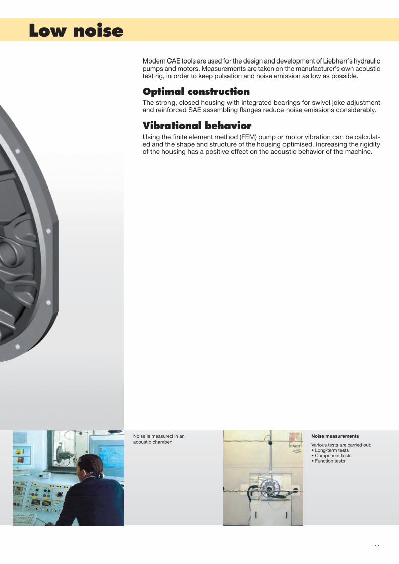
DPVOVariable displacement pump, open circuit 14-15
DPVDDouble variable displacement pump, open circuit 16-17
DPVPParallel pump – variable displacement, open circuit 18-19
DPVGVariable displacement pump, closed circuit 20-21
LPFConstant displacement pump, open circuit 22-23
LPVDDouble variable displacement pump, open circuit 24-25
Contents

13
Open circuit
Axial piston pumps are designed for hydrostatic open-circuit drives. The flow volume is proportional to the drive speed and the displacement volume.The volumetric flow can be varied steplessly by altering the displacement of the swashplate
Operating pressure range, suction side Absolute pressure at port SP abs min = 0,8 barP abs max= 2 bar
Operating pressure range, output sidePressure at port ASeries A: Nominal pressure PN = 350 bar; working pressure Pmax = 380 barSeries D:Nominal pressure PN = 380 bar; working pressure Pmax = 400 bar
Housing pressureThe maximum housing pressure of 2 bar should not be exceeded.
Direction of rotation Preferred direction of rotation: clockwiseCounter-clockwise rotation on request
Through drive Through drive to additional auxiliary pumps is possible on request.
Installed positionPreferred installed position: with suction port at bottom.Installed position to be avoided: regulating device at bottom.
Zero displacement volumeOnly possible for a short time at max. speed (risk of over-heating).
For further technical data, see pages 14 to 25.
Closed circuit
DPVG axial piston pumps are designed for closed circuit hydrostatic drives. The flow volume is proportional to the drive speed and displacement volume, and can be adjust-ed steplessly. As the swivel angle of the swashplate increases, the volu-metric flow rises from 0 toward its maximum value.Two high pressure limiting and feed valves protect the pump and the motor, and are integrated directly into the DPVG. The integrated auxiliary boost pump acts as a feed and control-circuit oil pump and is protected by a boost pres-sure relief valve. Integrated pressure cutoff is available as an option.
Operating pressure range Pressure at port A or B Nominal pressure PN = 450 bar Maximum pressure Pmax = 500 bar Boost pressure (at 2000 1/min) Psp = 20 to 35 bar
Auxiliary pumpSuction pressure Ps min = 0.8 bar absolute During cold start = 0.5 bar absolute
Temperature range The pumps are authorised to operate between - 25°C and 115°C.For operation below - 25°C please consult the manufacturer.
Pressure fluidsSee page 27
Fluid leakage pressure Permissible fluid leakage pressure = 2 bar
Installed position Any position is permitted. The housing must be filled with the pressure fluid and bled.
Direction of rotationEither direction is permitted
Hydraulic pumps

14
D F
G
ØA
E
B
C
Vg min Vg max
I
Vg min Vg max
px
Vg min Vg max
pB
Vg min Vg max
pB
Vg min Vg max
pB
Series D: variable displacement pump DPVO (open circuit)
Nominal pressure: 380 bar / Maximum pressure: 400 bar
Nominal size 108 165 215 215i*Displacement Vg max cm3 107.7 167.8 216.6 216.6
Max. speed at Vg max ** nmax min-1 2400 2100 2000 2500
Volumetric flow at nmax qv max L/min 258 352 433 542
Drive power p = 380 bar Pmax kW 163 223 274 343
Drive torque p = 380 bar Tmax Nm 651 1015 1310 1310
* with impeller.
** These values apply with an absolute pressure of 1 bar at the suction port. Higher suction limit values are possible if the suction pressure Pabs is raised at the suction port.
Product dimensions*** (mm) 108 165 215 215i*Splined shaft profile DIN 5480 tol. 9g W40x2x18 W45x2x21 W50x2x24 W50x2x24
Centering diameter A 361.95 447.7 447.7 165.1
Screw connecting diameter B 403 466.7 466.7 317.5
Fastening bores C 11 11 11 21
Splined shaft length D 46 49 45 49.1
SAE connection length, suction E 234.5 276.5 326 335
SAE connection length, pressure F 250.5 260.5 329.5 319
Overall length G 310.5 347.5 400 398
Pressure port SAE (6000 psi) 1" 1 1/4" 1 1/2" 1 1/2"
Suction port SAE (500 psi) 2 1/2" 3" 3 1/2" 3 1/2"
Oil leakage port M26x1.5 M26x1.5 M33x2 M33x2
*** Dimensions may vary according to configuration and additional equipment (installation drawing on request).
NoteVarious mounting flanges are possible (SAE J617a, SAE J744, DIN/ISO 3019)Integrated gear-type pump for control circuit oil is possible.Through-drive for pumps up to the same size as the installed pump is possible.
Control / regulation Other regulator function combinations available on request.
Electric proportional adjustment (positive or negative characteristic curve)
Hydraulic adjustment proporti- onal to control pressure (positive or negative characteristic curve)
Pressure control or pressure cutoff
Hyperbolic power regulation
Load Sensing

15
Type key for Series D hydraulic pumps
DPV O /Pump typeVariable displacement pump, series D DPV
Circuit typeOpen O
Nominal size108 165 215
Minimum displacement*0 - 15 % of Vg max, value in [cm3] • • • 000 - 032.5
* Other values on request
Control / regulation*Electric proportional adjustment / pressure cutoff • • EL / DA
Hyperbolic power control / load sensing • • • LR / LS
Hyperbolic power control / hydraulic adjustment proportional to control pressure/ pressure cutoff • LR / SD / DA
Electric proportional adjustment / load sensing • EL / LS
Fan drive • LU
Pressure control or pressure cutoff DA
* Other controls on request
Version1
2
Direction of rotation (looking at input shaft)right • • • R
left • • L
Mounting flange*Diesel engine flange SAE 1 (SAE J617a) 11
Diesel engine flange SAE 2 (SAE J617a) • • • 12
Diesel engine flange SAE 3 (SAE J617a) - 13
Diesel engine flange SAE 4 (SAE J617a) • • - 14
SAE D (SAE J744) - 24
SAE E (SAE J744) - - • 25
DIN / ISO 3019 • • 31 ...
Non-standard flange 51 ...
* Other mounting flanges on request
Shaft endSplined shaft DIN 5480 • • • 1
Splined shaft SAE J744 2
ConnectionsHigh-pressure ports: SAE (6000 PSI) • • •Suction ports: SAE (500 PSI) • • • A
Oil leakage and control pressure ports: metric (DIN 3852) • • •All ports: metric thread B
Charge pump / impellerWithout impeller • • - O
With impeller - - • I
Gear-type pump for control circuit oilWithout gear-type pump • • • 00
With gear-type pump Vg = 24 [cm3] • • 24
Through-driveWithout through-drive • • • 0
SAE A A
SAE B • • • B
SAE C C
SAE D • D
SAE E • E
Non-standard flange with through-drive • • K
•available on request- not available

16
DE
FG
A
B
C
Vg min Vg max
I
Vg min Vg max
pB
Series D: double variable displacement pump DPVD (open circuit)
Nominal pressure: 380 bar / Maximum pressure: 400 bar
Nominal size All data for each drive 108
Displacement Vg max cm3 107.7
Max. speed at Vg max* nmax min-1 2200
Volumetric flow at nmax qv max L/min 237
Drive power p = 380 bar Pmax kW 150
Drive torque p = 380 bar Tmax Nm 651
* These values apply with an absolute pressure of 1 bar at the suction port. Higher suction limit values are possible if the suction pressure Pabs is raised at the suction port. .
Product dimensions** (mm) 108Splined shaft profile DIN 5480 tol. 9g W40x2x18
Centering diameter A 511.18
Screw connecting diameter B 530.2
Fastening bores C 11
Splined shaft length D 45
Shaft collar / mounting flange E 48
Connection length, SAE flanges (suction and pressure) F 277.9
Overall length G 531.9
Pressure ports SAE (6000 psi) 1’’
Suction port SAE (500 psi) 3’’
Oil leakage port M33x2
** Dimensions may vary according to configuration and additional equipment (installation drawing on request).
Control / regulation Other regulator function combinations available on request.
Electric proportional adjustment
Pressure control or pressure cutoff
17
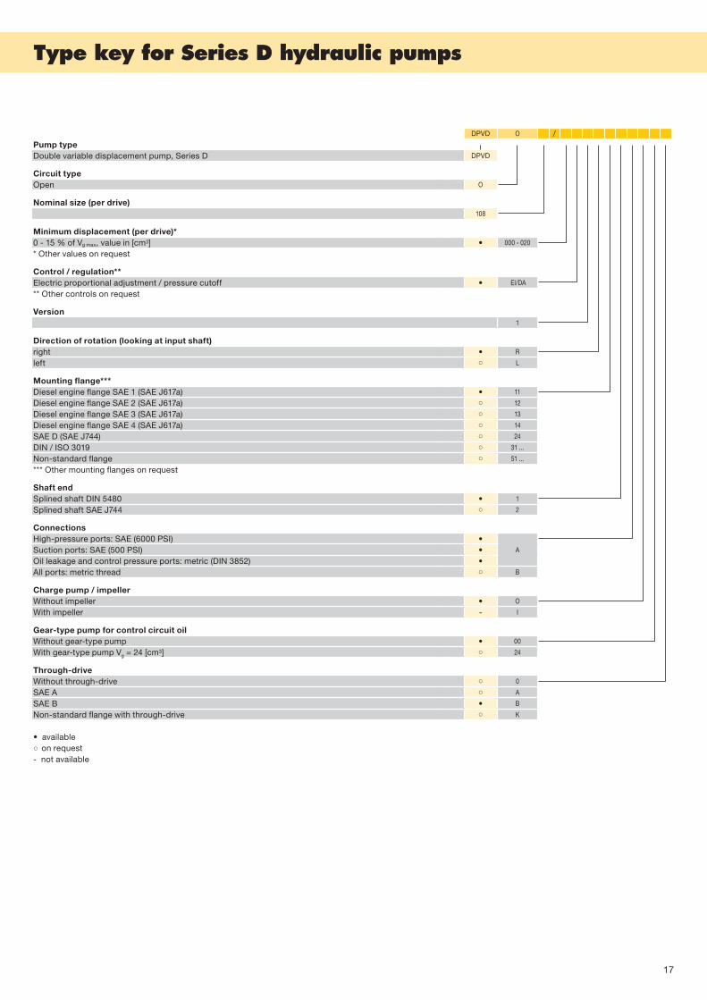
Type key for Series D hydraulic pumps
DPVD O /Pump typeDouble variable displacement pump, Series D DPVD
Circuit typeOpen O
Nominal size (per drive)108
Minimum displacement (per drive)*0 - 15 % of Vg max, value in [cm3] • 000 - 020
* Other values on request
Control / regulation**Electric proportional adjustment / pressure cutoff • El/DA
** Other controls on request
Version1
Direction of rotation (looking at input shaft)right • R
left L
Mounting flange***Diesel engine flange SAE 1 (SAE J617a) • 11
Diesel engine flange SAE 2 (SAE J617a) 12
Diesel engine flange SAE 3 (SAE J617a) 13
Diesel engine flange SAE 4 (SAE J617a) 14
SAE D (SAE J744) 24
DIN / ISO 3019 31 ...
Non-standard flange 51 ...
*** Other mounting flanges on request
Shaft endSplined shaft DIN 5480 • 1
Splined shaft SAE J744 2
ConnectionsHigh-pressure ports: SAE (6000 PSI) •Suction ports: SAE (500 PSI) • A
Oil leakage and control pressure ports: metric (DIN 3852) •All ports: metric thread B
Charge pump / impellerWithout impeller • O
With impeller - I
Gear-type pump for control circuit oilWithout gear-type pump • 00
With gear-type pump Vg = 24 [cm3] 24
Through-driveWithout through-drive 0
SAE A A
SAE B • B
Non-standard flange with through-drive K
•available on request- not available

18
Vg min Vg max
I
Vg min Vg max
px
Vg min Vg max
pB
Vg min Vg max
pB
Vg min Vg max
pB
DE
FG
B
CA
Vg min Vg max
p1+2
Series D: parallel variable displacement pump DPVP (open circuit)
Nominal pressure: 380 bar / Maximum pressure: 400 bar
Nominal size All data for each power unit 108 165 165i*
Displacement Vg max cm3 107.7 167.8 167.8
Max. drive speed at Vg max** nmax min-1 2300 2100 2600
Volumetric flow at nmax qv max L/min 248 352 436
Drive power p = 380 bar Pmax kW 163 223 276
Drive torque p = 380 bar Tmax Nm 651 1015 1015
* with impeller.
** These values apply with an absolute pressure of 1 bar at the suction port. Higher suction limit values are possible if the suction pressure Pabs is raised at the suction port.
Product dimensions*** (mm) 108 165 165i*Splined shaft profile DIN 5480 tol. 9g W50x2x24 W70x3x22 W70x3x22
Centering diameter A 511.18 **** 511.18 511.18
Screw connecting diameter B 530.2 530.2 530.2
Fastening bores C 11 11 11
Splined shaft length D 45 67 67
Shaft collar / mounting flange E 46 26,5 26,5
SAE connection length pressure F 369.4 423 423
Overall length G 462 517.9 605.9
Pressure ports SAE (6000 psi) 1" 1 1/4" 1 1/4"
Suction port SAE (500 psi) 3" 4" 3"
Oil leakage port M33x2 M33x2 M33x2
*** Dimensions may vary according to configuration and additional equipment (installation drawing on request).**** DPVP 108 also available with SAE-2 mounting flange.
NoteDPVP pumps can be used in single or twin circuit systems.Integrated gear-type pump for control circuit oil (24 cc) standard on output II, other versions on request.Pump transmission housing with and without 3rd output (direction of rotation left or right possible at output III).Through-drives to output I and/or output II are possible.Different pump transmission ratios are possible (precise data available on request)
Control / regulation Other regulator function combinations available on request.
Electric proportional adjustment (positive or negative character- istic curve)
Hydraulic adjustment propor-tional to control pressure (positive or negative character-istic curve)
Pressure control or pressure cutoff
Hyperbolic power regulation
Load Sensing Cumulative power regulation

19
Type key for Series D hydraulic pumps
DPVP O /Pump typeParallel variable displacement pump, Series D DPVP
Circuit typeOpen O
Nominal size (per drive)108 165
Minimum displacement (per drive)*0 - 15 % of Vg max, value in [cm3] • • 000 - 034
* Other values on request
Control / regulation**Electric proportional adjustment / pressure cutoff EL / DA
Hyperbolic power control / load sensing • LR / LS
Cumulative power control / Adjustment proportional to control pressure • • SL / SD
Hyperbolic power control / Adjustment proportional to control pressure / pressure cutoff • • LR / SD / DA
Electric proportional adjustment / Load sensing • • EL / LS
** Other controls on request
Version1
Direction of rotation (looking at input shaft)right • • R
left - - L
Mounting flangeDiesel engine flange SAE 1 (SAE J617a) • • 11
Diesel engine flange SAE 2 (SAE J617a) • - 12
Shaft endSplined shaft DIN 5480 • • 1
Splined shaft SAE J744 2
ConnectionsHigh-pressure ports: SAE (6000 PSI) • •
ASuction ports: SAE (500 PSI) • •Oil leakage and control pressure ports: metric (DIN 3852) • •All ports: metric thread B
Charge pump / impellerWithout impeller • • O
With impeller - • I
Gear-type pumpWithout gear-type pump 00
With gear-type pump Vg = 24 [cm3] • • 24
Through-drive (side P1 and / or P2)Without through-drive • • 0
SAE A A
SAE B • • B
SAE C C
SAE D D
•available on request- not available

20
-Vg max +Vg max
I
0 -Vg max +Vg max
px
0 -Vg max +Vg max
pB
0
A
D
E
F
G
H
9
B
C
Series D: variable displacement pump DPVG (closed circuit)
Nominal pressure: 450 bar / Maximum pressure: 500 bar
Nominal size 108 165 250
Displacement Vg max cm3 107.7 167.8 250.5
Max. speed at Vg max nmax min-1 3000 2700 2400
Volumetric flow at nmax qv max L/min 323 453 601
Drive power p = 430 bar Pmax kW 232 325 431
Drive torque p = 430 bar Tmax Nm 737 1149 1715
Product dimensions* (mm) 108 165 250Splined shaft profile DIN 5480 tol. 9g W40x2x18 W45x2x21 W55x2x26
Centering diameter A 180 200 224
Screw connecting diameter B 224 250 280
Fastening bores C 17 21 22
Splined shaft length D 45 51 56
Height adjustment E 190 206 225.5
SAE connection length, pressure F 223 270 293
Length without/with integrated feed pump G 268 / 315.5 - / 323 366.5 / -
Overall length H 330.5 358.5 392.5
Pressure ports SAE (6000 psi) 1" 1 1/4" 1 1/2"
Oil leakage port M33x2 M42x2 M42x2
* Dimensions may vary according to configuration and additional equipment (installation drawing on request).
NoteDifferent mounting flanges are possible (SAE J617a, SAE J744, DIN/ISO 3019).With/without integrated boost pump; integrated boost pressure relief valve is possible.Through drive for pumps up to same size is possible.HD port are possible at the side or underneath.
Control / regulation Other regulator function combinations available on request.
Electric proportional adjustment Hydraulic proportional adjustment depending on control pressure
Pressure cutoff

21
Series D: variable displacement pump DPVG (closed circuit)
Nominal pressure: 450 bar / Maximum pressure: 500 bar
Type key for Series D hydraulic pumps
DPVG G /Pump typeVariable displacement pump, series D DPVG
Circuit typeclosed G
Nominal size108 165 250
Minimum displacementVg min = 0 (cm3) • • • 000
Control / regulationElectric proportional adjustment / pressure cutoff • • • EL / DA
Electric proportional adjustment • EL
Hydraulic proportional adjustment depending on control pressure SD
Torque control, hydraulic • TCH
Torque control, electric TCE
Speed control, hydraulic DZH
Speed control, electric DZE
Version1
Direction of rotation (looking at input shaft)right • • • R
left • • • L
Mounting flange*Diesel engine flange SAE 1 (SAE J617a) 11
Diesel engine flange SAE 2 (SAE J617a) 12
Diesel engine flange SAE 3 (SAE J617a) 13
Diesel engine flange SAE 4 (SAE J617a) - 14
SAE D (SAE J744) - 24
SAE E (SAE J744) - • 25
DIN / ISO 3019 • • • 31 ...
Transmission flange 41 ...
Non-standard flange 51 ...
* Other mounting flanges on request
Shaft endSplined shaft DIN 5480 • • • 1
Splined shaft SAE J744 2
ConnectionsHigh pressure ports: SAE (6000 PSI) • • •Suction ports: SAE (500 PSI) • • A
Oil leakage and control pressure ports: metric (DIN 3852) • • •All ports: metric thread B
AttachmentsNo attachment • • • O
Integrated boost pump**Without boost pump • • 00
With boost pump, Vg = 30 [cm3] • 30
With boost pump, Vg = 40 [cm3] • 40
With boost pump, Vg = 50 [cm3] • 50
** Other nominal sizes on request
Through-driveWithout through-drive • 0
SAE A A
SAE B • • • B
SAE C C
SAE D • D
SAE E E
Non-standard flange with through-drive • • K
ValveFeed valve • • • NS
High pressure relief valve • • • DB
•available on request- not available

22
G
E
F
D
B
ØA
C
Series A: constant displacement pump LPF (open circuit)
Nominal pressure: 350 bar / Maximum pressure: 380 bar
Nominal size 45 75
Displacement Vg max cm3 45.6 75
Max. speed at Vg max nmax min-1 2700 2540
Volumetric flow at nmax qv max L/min 123 191
Drive power p = 350 bar Pmax kW 82 127
Drive torque p = 350 bar Tmax Nm 290 478
Product dimensions* (mm) 45 75Splined shaft profile DIN 5480 tol. 9g W30x2x14 W35x2x16
Centering diameter A 100 125
Screw connecting diameter B 125 160
Fastening bores C 11.5 14
Splined shaft length D 35 41.5
SAE connection length, suction E 199.5 221.5
SAE connection length, pressure F 186 205
Overall length G 238 266
Pressure port SAE (6000 psi) 3/4" 1"
Suction port SAE (500 psi) 2" 2"
Oil leakage port M18x1.5 M18x1.5
* Dimensions may vary according to configuration and additional equipment (installation drawing on request).
23
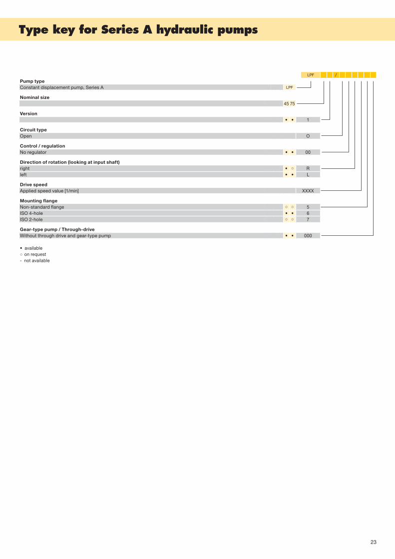
Type key for Series A hydraulic pumps
LPF /Pump typeConstant displacement pump, Series A LPF
Nominal size45 75
Version• • 1
Circuit typeOpen O
Control / regulationNo regulator • • 00
Direction of rotation (looking at input shaft)right • Rleft • • L
Drive speedApplied speed value [1/min] XXXX
Mounting flange Non-standard flange 5ISO 4-hole • • 6ISO 2-hole 7
Gear-type pump / Through-driveWithout through drive and gear-type pump • • 000
•available on request- not available

24
C
B
FE
D
ØA
Vg min Vg max
I
Vg min Vg max
px
Vg min Vg max
pB
Vg min Vg max
pB
Vg min Vg max
pB
Series A: Double variable displacement pump LPVD (open circuit)
Nominal pressure: 350 bar / Maximum pressure: 380 bar
Nominal sizeAll data for each power unit 45 64 75 90 100 107 125 140 150Displacement Vg max cm3 45.6 64.3 75 90.7 103.1 107.6 125.6 141.2 151.4
Max. speed at Vg max* nmax min-1 3000 2760 2540 2430 2320 2290 2180 2150 2100
Volumetric flow at nmax qv max L/min 137 177 191 220 239 246 274 304 318
Drive power p = 350 bar Pmax kW 91 118 127 147 159 164 183 203 212
Drive torque p = 350 bar Tmax Nm 290 408 477 578 654 684 802 902 964
* These values apply with an absolute pressure of 1 bar at the suction port. Higher suction limit values are possible if the suction pressure Pabs is raised at the suction port.
Product dimensions** (mm) 45 64 75 90 100 107 125 140 150Splined shaft profile DIN 5480 Tol. 9g W30x2x14 W35x2x16 W35x2x16 W35x2x16 W40x2x18 W40x2x18 W40x2x18 W40x2x18 W40x2x18
Centering diameter A 127 361.95 447.7 447.7 447.7 447.7 511.18 160 160
Screw connecting diameter B 246.4 381 466.7 466.7 466.7 466.7 530.2 310 310
Fastening bores C 17 11 11 11 17 11 11 18 18
Splined shaft length D 35 41 41.5 41 47.25 47.25 47 46 46
Connection length. SAE flanges (suction and pressure) E 219 249 259 283.5 258 258 310 310 310
Overall length F 449 517 561 563.5 583 583 624 624 624
Pressure ports SAE (6000 psi) 3/4" 1" 1" 1" 1" 1" 1 1/4" 1 1/4" 1 1/4"
Suction port SAE (500 psi) 2 1/2" 3" 3" 3" 3" 3" 3 1/2" 3 1/2" 3 1/2"
Oil leakage port M33x2 M26x1.5 M33x2 M26x1.5 M33x2 M33x2 M33x2 M33x2 M32x2
** Dimensions may vary according to configuration and additional equipment (installation drawing on request).
Control / regulation Other regulator function combinations available on request.
Electric proportional adjustment (positive or negative characteristic curve)
Hydraulic adjustment proporti-onal to control pressure (posi-tive or negative characteristic curve)
Pressure control or pressure cutoff
Power regulation Load Sensing

25
Type key for Series A hydraulic pumps
LPVD / OPump type Double variable displacement pump. Series A LPVD
Nominal size (per drive)45 64 75 90 100 107 125 140 150
Version1
Circuit typeOpen O
Control / regulationPressure cutoff • - - - - - - • - DAElectric proportional adjustment / pressure cutoff - - - - - - • • - EL / DAElectric proportional adjustment / pressure cutoff can be overridden - - - - - - - • - EL / DA / UEElectric proportional adjustment/ load sensing / pressure cutoff - - - - • - - • • EL / LS / DAElectric proportional adjustment with stroke limiting / pressure cutoff can be overridden - - - - - • - - - EL/HB/DA/UEPower regulation / load sensing - - - - • • - - - LR / LSPower regulation / hydraulic adjustment proportional to control pressure/ pressure cutoff - - - - - - • • • LR / SD / DACumulative power control - • • - - - - - - SLHydraulic adjustment proportional to control pressure/ pressure cutoff - - - - - - • - - SD / DAHydraulic adjustment proportional to control pressure with power limiting - - - - - - • - - SD / LBCumulative power control with stroke limiting - - - • - - - - - SL / HBCumulative power control with power adjustment - - • - - - - - - SL / LVHydraulic adjustment proportional to control pressure with power adjustment - - - - - - • - - SD / LV
Direction of rotation (looking at input shaft)right - • • • • • • • • Rleft • - - - • - • • • L
Drive speed
Applied speed value [1/min]
- - • - - - - - - 1450- - - - - - • • • 1800- - - - - - • - - 1950- - - - - - • • - 1952• • • • • • - - • 2000- - - - - - - - • 2025- - - - - - • • - 2093- - • - - - - • • 2100- - - - • - - - - 2144- • - - - - - - - 2300- - - - - - - - • 2500
Mounting flange Diesel engine flange SAE 1 (SAE J617a) • 1Diesel engine flange SAE 2 (SAE J617a) • • • • • • • 2Diesel engine flange SAE 3 (SAE J617a) 3Diesel engine flange SAE 4 (SAE J617a) • 4Non-standard flange • • • • • 5ISO 4-hole • • • 6ISO 2-hole 7Transmission flange • • • 8
Through-drive / Control oil. gear-type pumpWithout through-drive and gear-type pump • • • • • • • 000Gear-type pump with Vg = 22 [cm3] and through-drive with SAE-A flange 22 AGear-type pump with Vg = ... [cm3] and through-drive with SAE-B flange • • • • ... BGear-type pump with Vg = ... [cm3] and through-drive with SAE-C flange … CGear-type pump with Vg = ... [cm3] and through-drive with non-standard flange … DGear-type pump with Vg = ... [cm3] and without through-drive • • • • … INon-standard flange without through-drive 005Non-standard flange with through-drive • • • 006
Minimum Flow rate
Indication of minimum Flow rate [l/min]
- - • - • • • • • 00• - - - - - - - - 10- - - - - • - - - 25- - - - - - • - - 31- - - - - - - • - 35- • - - - - - - - 47- - • - - - - - - 52- - • - - - - - - 55- - - - - - • - - 58- - - • - - - - - 60- - - - - - - - • 72
Maximum Flow rate
Indication of maximum Flow rate [l/min]
• - - - - - - - - 90- - • - - - - - - 94- • - - - - - - - 125- • - - - - - - - 128- - • - - - - - - 150- - • - - - - - - 157,5- - - • - - - - - 180- - - - • • - - - 200- - - - • • - - - 215- - - - - - • - - 225- - - - - - • - - 230- - - - - - - • - 259- - - - - - • • - 260- - - - - - - - • 272- - - - - - - • - 273- - - - - - - • - 282- - - - - - - • - 294- - - - - - - - • 300- - - - - - - - • 304- - - - - - - - • 314- - - - - - - - • 315
•available on request- not available

26
DMVAVariable displacement motor 28-29
DMFAFixed displacement motor 30-31
DMVDVariable displacement double motor 32-33
CMVEVariable displacement plug-in motor, open circuit 34-35
LMFFixed displacement motor 36-37
FMFFixed displacement plug-in motor 38-39
FMVVariable displacement plug-in motor, open circuit 40-41
Contents

27
Hydraulic motors
Liebherr axial piston motors (DMVA, DMFA, DMVD, CMVE, LMF, FMF, FMV) are of the swashplate type and designed for open and closed circuit hydrostatic drives. The motors are suitable for mobile applications.The output speed is proportional to the displacement flow and inversely proportional to the displacement.Through-drives and attached holding brakes are availa-ble on request.
Operating pressure rangePressure at port A and BWorking pressure (see technical data)Maximum housing pressure = 2 bar
Direction of rotationClockwise and counter-clockwise
Installed positionAny suitable positionAn oil leakage port at the top should be arranged to drain into the tank.
Through-driveon request.
Fill housing with oil before start-up.If special pressure fluids are to be used, please discuss this with the manufacturer.
For further technical data, see pages 28 to 41.
Pressure fluidsWhen choosing pressure fluids and operating conditions, please comply with the Liebherr “Lubricants and operating fluids” data sheets.
If operating with HF or environment-friendly pressure fluids, note that restrictions may be stated in the technical sheets; please consult the manufacturer if necessary (when orde-ring, please state which pressure fluid is to be used).Operation with HFA, HFB and HFC pressure fluids calls for special additional measures.
Operating viscosity rangeWe recommend selecting an operating viscosity (at re-gular operating temperature) in the range that is optimal with regard to efficiency and operating time, namely Vopt
= optimal operating viscosity 16 ... 36 mm2/s, referred to the circuit temperature.
Viscosity limitsThe following values apply in extreme conditions:Vmin = 10 mm2/s
For a short period, max. permitted temperature of tmax = 115°C
Make sure that the maximum pressure fluid temperature of 115º C is not exceeded even locally (for instance in the vicinity of bearings).Vmax = 1600 mm2/sFor a short period during a cold start (tmin = -25ºC).At temperatures between -25º C and -40º C special mea-sures are needed; please consult the manufacturer.

28
Vg min Vg max
px
Vg min Vg max
pB
D 9
A
E
F
C
B
Vg min Vg max
I
Vg min Vg max
px
Vg min Vg max
pB
Series D: DMVA motor (variable displacement)
NG108 & NG165: Closed circuit - nominal pressure: 450 bar / maximum pressure: 500 barNG355: Closed circuit - nominal pressure: 380 bar / maximum pressure: 400 bar Open circuit - nominal pressure: 380 bar / maximum pressure: 400 bar
Nominal size 108 165 355
Displacement Vg max cm3 107.7 167.8 355.6
Max. speed at Vg max and p max nmax min-1 3350 3000 2400
Max. speed at Vg / Vg max = 0,65 and p = 200 bar nmax min-1 5125 4590 3670
Flow at nmax qv max L/min 361 503 853
Output power p = 430 bar, NG355 with p = 360 bar Pmax kW 259 361 512
Output torque p = 430 bar, NG355 with p = 360 bar Tmax Nm 737 1149 2038
Product dimensions* (mm) 108 165 355Splined shaft profile DIN 5480 tol. 9g W40x2x18 W45x2x21 W60x2x28
Centering diameter A tol. h8 160 180 250
Screw connecting diameter B 200 224 -
Fastening bores C 17 18 26
Splined shaft length D 45 51 69
SAE connection length E 309 357 433.5
Overall length F 199 226 496
Pressure ports SAE (6000 psi) 1" 1 1/4" 1 1/2"
Oil leakage port M26x1.5 M26x1.5 M33x2
* Dimensions may vary according to configuration and additional equipment (installation drawing on request).
NoteA brake valve can be attached.The pressure port can be at the rear or side on the connecting plate.
Control / regulation Other regulator function combinations available on request.
Electrical adjustment with pro-portional magnet (positive or negative characteristic curve)
Hydraulic adjustment, depend-ing on control pressure (positive or negative characteristic curve)
Pressure cutoff Hydraulic adjustment, high-pressure related
Hydraulic two-point control

29
Series D: DMVA motor (variable displacement)
NG108 & NG165: Closed circuit - nominal pressure: 450 bar / maximum pressure: 500 barNG355: Closed circuit - nominal pressure: 380 bar / maximum pressure: 400 bar Open circuit - nominal pressure: 380 bar / maximum pressure: 400 bar
Type key for Series D hydraulic motors
DMVA /Motor type
DMVA
Circuit typeopen O
closed G
Nominal size108 165 355
Minimum displacement*0 - 66 [cm3] • - - 0 - 66
41,2 - 151,9 [cm3] - • - 41.2 - 151.9
270 [cm3] (non-adjustable) - - • 270
100 [cm3] (adjustable) - - • 0 - 100
* Other values on request
Control / regulationHydraulic adjustment high pressure related • • HD
Hydraulic adjustment depending on control pressure / pressure cutoff • • SD / DA
Electrical adjustment with proportional magnet • • • EL Hydraulic two point control • ZH
Electrical adjustment with proportional magnet/ pressure cutoff • • EL / DA
Version1
Direction of rotation (looking at input shaft)right - - - R
left - - - L
alternating • • • W
Mounting flange**DIN / ISO 3019 • • 31…
Non-standard flange • 51…
** Other attachment flanges on request
Shaft endSplined shaft DIN 5480 • • • 1
Splined shaft SAE J744 2
ConnectionsHigh pressure ports: SAE (6000 PSI) • • •
AOil leakage and control pressure ports: metric (DIN 3852) • • •All ports: metric thread B
Additional equipmentNo add-on equipment • • • 0
Through-driveWithout through-drive • • 0
Non-standard flange with through-drive • K
Valve / sensornone • 00
Flushing for closed circuit • • SO
Flushing for closed circuit with high pressure relief valve SH
Flushing for closed circuit • MO
Flushing for open circuit with high pressure relief valve MH
Resuction valve with high pressure relief valve NH
Resuction valve with hydraulically adjustable high pressure relief valve NX
Hydraulically adjustable high pressure relief valve OX
Brake valve + DBV • • BH
High pressure relief valve • • DB
Feed valve NS
Speed sensor • D
•available on request- not available

30
D 9
A
E
F
B
CSeries D: DMFA motor (fixed displacement)
Open and closed circuit - Nominal pressure: 380 bar / Maximum pressure: 400 bar
Nominal size 355
Displacement Vg max cm3 355.6
Max. speed at Vg max and p = 360 bar nmax min-1 2400
Flow at nmax qv max L/min 853
Output power p = 360 bar Pmax kW 512
Output torque p = 360 bar Tmax Nm 2034
Product dimensions* (mm) 355Splined shaft profile DIN 5480 tol. 9g W60x2x28
Centering diameter A tol. h8 200
Screw connecting diameter B **
Fastening bores C 26
Splined shaft length D 71
SAE connection length E 351.5
Overall length F 467.5
Pressure ports SAE (6000 psi) 1 1/2"
Oil leakage port M33x2
* Dimensions may vary according to configuration and additional equipment (installation drawing on request). ** 4-hole non-standard flange.
NoteFlushing valve integrated into connection plate.External brake valve can be attached to SAE port.An external Liebherr multi-disc brake can be attached (non-standard flange with through drive shaft).

31
Type key for Series D hydraulic motorsSeries D: DMFA motor (fixed displacement)
Open and closed circuit - Nominal pressure: 380 bar / Maximum pressure: 400 bar
DMFA /Motor typeFixed displacement motor, series D DMFA
Circuit typeopen O
closed G
Nominal size355
Control / regulationNo regulation • 00
Version1
Direction of rotation (looking at input shaft)right - R
left - L
alternating • W
Mounting flange *DIN / ISO 3019 31 ...
Non-standard flange • 51 ...
* Other mounting flanges on request
Shaft endSplined shaft DIN 5480 • 1
Splined shaft SAE J744 2
ConnectionsHigh pressure ports: SAE (6000 PSI) •
AOil leackage and control pressure ports: metric (DIN 3852) •All ports: metric thread B
Additional equipmentNo add-on equipment • 0
Multi-disc brakes L
Through-driveWithout through-drive 0
Non-standard flange with through-drive • K
Valve / sensornone 00
Flushing valve, closed circuit • SO
Flushing valve, closed circuit with high pressure relief valve SH
Flushing valve, open circuit MO
Flushing valve, open circuit with high pressure relief valve • MH
Resuction valve with high pressure relief valve NH
Resuction valve with hydraulically adjustable high pressure relief valve NX
Hydraulically adjustable high pressure relief valve OX
Brake valve + DBV BH
High pressure relief valve DB
Feed valve NS
Speed sensor • D
•available on request- not available

32
Vg min Vg max
I
D 18C
A
G
HFE
B
Vg min Vg max
pB
Series D: DMVD double motor (variable displacement)
Closed circuit - Nominal pressure: 450 bar / Maximum pressure: 500 bar
Nominal size 165/108 165/165
Displacement Vg max cm3 275 335
Max. speed at Vg max and p = 430 bar nmax min-1 3000 3000
Max. speed at Vg / Vg max = 0,65 and p = 200 bar nmax min-1 4590 4590
Flow at nmax qv max L/min 825 1005
Output power p = 430 bar Pmax kW 591 720
Output torque p = 430 bar Tmax Nm 1883 2294
Product dimensions* (mm) 165/108 165/165Splined shaft profile DIN 5480 tol. 9g W45x2x21 W45x2x21
Centering diameter A tol. h8 180 180
Screw connecting diameter B 224 224
Fastening bores C 18 18
Splined shaft length D 55 55
Regulator width dimension E 157 157
SAE flange width dimension F 145 148
SAE flange connection length G 277 277
Overall length H 539 567
Overall width I 240 250
Pressure ports SAE (6000 psi) 1 1/4" 1 1/4"
Oil leakage port M26x1.5 M26x1.5
* Dimensions may vary according to configuration and additional equipment (installation drawing on request).
NoteThrough-drive possible.
Control / regulation Other regulator function combinations available on request.
Electrical adjustment with pro-portional magnet (positive or negative characteristic curve)
Pressure cutoff

33
Type key for Series D hydraulic motorsSeries D: DMVD double motor (variable displacement)
Closed circuit - Nominal pressure: 450 bar / Maximum pressure: 500 bar
DMVD G /Motor typeVariable displacement motor, Series D DMVD
Circuit typeclosed G
Nominal size165/108 165/165
Minimum displacement*0 - 100 [cm3] • • 000 - 100
* Other values on request
Control / regulationElectric proportional adjustment • • EL
Electric proportional adjustment / pressure cutoff • • EL / DA
Version1
Direction of rotation (looking at input shaft)right - - R
left - - L
alternating • • W
Mounting flange**DIN / ISO 3019 • • 31…
Non-standard flange 51…
** Other mounting flanges on request
Shaft endSplined shaft DIN 5480 • • 1
Splined shaft SAE J744 2
ConnectionsHigh pressure ports: SAE (6000 PSI) • •
AOil leakage and control pressure ports: metric (DIN 3852) • •All ports: metric thread B
Additional equipmentNo add-on equipment • • O
Through-driveWithout through-drive • • 0
Non-standard flange with through-drive • K
Valve / sensornone 00
Flushing valve, closed circuit • • SO
Flushing valve, closed circuit with high pressure relief valve SH
Flushing valve, open circuit MO
Flushing valve, open circuit with high pressure relief valve MH
Resuction valve with high pressure relief valve NH
Resuction valve with hydraulically adjustable high pressure relief valve NX
Hydraulically adjustable high pressure relief valve OX
Brake valve + DBV BH
High pressure relief valve DB
Feed valve NS
Crawling speed K
Speed sensor • • D
•available on request- not available

34
F
A
G
C
B
E
F
D
Vg min Vg max
px
Series C: CMVE variable displacement plug-in motor (open circuit)
Nominal pressure: 380 bar / Maximum pressure: 400 bar
Nominal size 108 165
Displacement Vg cm3 108 165.9
Max. speed at Vg max and p = 360 bar nmax min-1 3470 3000
Max. speed at Vg / Vg max = 0,65 and p = 200 bar nmax min-1 4500 4200
Flow at nmax qv max L/min 375 498
Output power p = 360 bar Pmax kW 225 299
Output torque p = 360 bar Tmax Nm 619 951
Product dimensions* (mm) 108 165Splined shaft profile (internal splines) DIN 5480 Tol. 9g N35x2x16 N40x2x18
Centering diameter A Tol. h8 215 240
Screw connecting diameter B ** **
Fastening bores C 15 17
Splined shaft length D 26.5 37.5
Insertion length E 122 137
SAE flange connecting length F 150 182
Overall length G 312.5 374
Pressure ports SAE (6000 psi) 1" 1 1/4"
Oil leakoff port M26x1.5 M26x1.5
* Dimensions may vary according to configuration and additional equipment (installation drawing on request).** 4-hole special attachment flange.
NoteThis motor is mainly intended for installation in a mechanical travel drive (FAT).Integrated brake valve, pressure relief valves and internal multi-disc brake.
Control / regulationHydraulic two-point control

35
Series C: CMVE variable displacement plug-in motor (open circuit)
Nominal pressure: 380 bar / Maximum pressure: 400 bar
Type key for Series C hydraulic motors
CMVE O /Motor typeVariable displacement plug-in motor, Series C CMVE
Circuit typeOpen O
Nominal size108 165
Minimum displacement*Vg min= 65 (cm3) • 65
Vg min= 79 (cm3) • 79
Vg min= 97 (cm3) • 97
* Other values on request
Control / regulationHydraulic two-point control • • ZH
Version1
Direction of rotation (looking at input shaft)right - - R
left - - L
alternating • • W
Mounting flangeNon-standard flange • • 51…
Shaft endSplined shaft DIN 5480 • • 1
Splined shaft SAE J744 2
ConnectionsHigh pressure ports: SAE (6000 PSI) • •
AOil leakage and control pressure ports: metric (DIN 3852) • •All ports: metric thread B
Additional equipmentNo add-on equipment 0
Multi-disc brake (integrated) • • L
Through-driveWithout through-drive • • 0
Non-standard flange with through-drive - - K
Valve / sensornone 00
Flushing valve, closed circuit - - SO
Flushing valve, closed circuit with high pressure relief valve - - SH
Flushing valve, open circuit MO
Flushing valve, open circuit with high pressure relief valve MH
Resuction valve with high pressure relief valve NH
Resuction valve with hydraulically adjustable high pressure relief valve NX
Hydraulically adjustable high pressure relief valve OX
Brake valve + DBV • • BH
High pressure relief valve DB
Feed valve - - NS
Speed sensor D
•available on request- not available

36
C
BØ A
G
F
ED
Series A: LMF motor (fixed displacement)
Open and closed circuit - Nominal pressure: 350 bar / Maximum pressure: 380 bar
Nominal size 107 125Displacement Vg max cm3 107 125.6
Max. speed at Vg max and p = 330 bar nmax min-1 3540 3290
Flow at nmax qv max L/min 379 413
Output power p = 330 bar Pmax kW 208 227
Output torque p = 330 bar Tmax Nm 562 660
Product dimensions* (mm) 107 125Splined shaft profile DIN 5480 tol. 9g W40x2x18 W40x2x18
Centering diameter A tol. h8 160 160
Screw connecting diameter B 200 200
Fastening bores C 18 18
Splined shaft length D 45 45
SAE connection length E 253.0 253.0
Overall length F 292.0 292.0
Pressure ports SAE (6000 psi) 1 1/4" 1 1/4"
Oil leakage port R 3/4 R 3/4
* Dimensions may vary according to configuration and additional equipment (installation drawing on request).
NoteExternal brake valve can be attached to SAE port.

37
Type key for Series A hydraulic motors
LMF /Motor typeFixed displacement motor, Series A LMF
Nominal size107 125
Version1
Control / regulationNo regulator • • 00
Valvesnone • 00Flushing valve, closed circuit SOFlushing valve, closed circuit with high pressure relief valve SHFlushing valve, open circuit MOFlushing valve, open circuit with high pressure relief valve MHResuction valve with high pressure relief valve NHResuction valve with hydraulically adjustable high pressure relief valve NXExternal brake valve • BN
Mounting flangeISO 4-hole • • 6
Through-driveWithout through-drive • • 00Non-standard flange with through-drive 10
Additional functionSpeed sensor D
•available on request- not available

38
C
BØ A
G
FED
Series A: FMF plug-in motor (fixed displacement)
Open and closed circuit - Nominal pressure: 350 bar / Maximum pressure: 380 bar On request up to nom. size 64 : Nominal pressure: 420 bar / Maximum pressure: 450 bar
Nominal size 25 28 32 45 58 64 90 100 125 165 250Displacement Vg max cm3 25 28 31.8 45.6 58.3 64.3 90.7 103.2 125.7 165.9 256.8
Max. speed at Vg max and p = 330 bar nmax min-1 5180 5180 5180 4620 4110 4110 3670 3540 3290 3000 2606
Flow at nmax qv max L/min 130 145 165 211 240 264 333 365 414 498 669
Output power p = 330 bar Pmax kW 71 80 91 116 132 145 183 201 227 274 368
Output torque p = 330 bar Tmax Nm 131 147 167 240 306 338 477 542 661 872 1349
Product dimensions* (mm) 25 28 32 45 58 64 90 100 125 165 250Splined shaft profile DIN 5480 tol. 9g W25x1.25x18 W25x1.25x18 W25x1.25x18 W30x2x14 W35x2x16 W35x2x16 W35x2x16 W40x2x18 W40x2x18 W45x2x21 W50x2x24
Centering diameter A tol. h8 135 135 135 160 170 170 190 190 210 230 260
Screw connecting diameter B 160 160 160 200 200 200 224 224 248 280 310
Fastening bores C 13 13 13 18 17 17 21 21 21 26 26
Splined shaft length D 30 30 30 35 40 40 40 45 45 50 55
Insertion length E 88.5 88.5 88.5 92.3 92.3 92.3 110.5 110.5 122.8 130 145
SAE flange connecting length F 179.5 179.5 179.5 192 215 215 234.5 234.5 265 285 309
Overall length G 219.5 223.1 219.5 222 262 256 269.5 269.5 302 331 359
Pressure ports SAE (6000 psi) 1/2" 1/2" 1/2" 3/4" 1" 3/4"ou 1" 1" 1" 1 1/4" 1 1/4" 1 1/4"
Oil leakage port M16x1.5 M16x1.5 M16x1.5 M18x1.5 M18x1.5 M18x1.5 M26x1.5 R 3/4" R 3/4" M33x2 M33x2
* Dimensions may vary according to configuration and additional equipment (installation drawing on request).
NoteExternal brake valve can be attached to SAE union.

39
Type key for Series A hydraulic motors
FMF /
Motor type
Fixed displacement plug-in motor, Series A FMF
Nominal size
25 28 32 45 58 64 90 100 125 165 250
Version
1
Control / regulation
No regulator 00
Valves
none • • • • 00
Flushing valve, closed circuit • • • • • • SO
Flushing valve, closed circuit with high pressure relief valve SH
Flushing valve, open circuit • • MO
Flushing valve, open circuit with high pressure relief valve • • MH
Resuction valve with high pressure relief valve • • • • • • • NH
Resuction valve with hydraulically adjustable high pressure relief valve • • • • NX
Hydraulically adjustable high pressure relief valve OX
External brake valve + DBV • • BN
Resuction valve with high pressure relief and damping valve • DV
Mounting flange 25 28 32 45 58 64 90 100 125 165 250
2-hole flange • • • • • • • • • • • 7
Through-drive
Without through-drive • • • • • • • • • • • 00
Non-standard flange with through-drive - - - - - - - - - - - 10
Additional function
Speed sensor • • • • • • • D
•available
on request
- not available

40
C
BØ A
G
FED
Vg min Vg max
px
Series A: FMV variable displacement plug-in motor (open circuit)
Nominal pressure: 350 bar / Maximum pressure: 380 bar On request up to nom. size 75 : Nominal pressure: 420 bar / Maximum pressure: 450 bar
Nominal size 75 100 140 165 250
Displacement Vg cm3 75 103.1 141.2 165.8 256.8
Max. speed at Vg max and p = 330 bar nmax min-1 3900 3540 3160 3000 2600
Max. speed at Vg / Vg max = 0,65 and p = 200 bar nmax min-1 5460 4950 4420 4200 3640
Flow at nmax qvmax L/min 293 365 446 497 668
Output power p = 330 bar Pmax kW 161 201 245 274 367
Output torque p = 330 bar Tmax Nm 394 542 742 871 1349
Product dimensions* (mm) 75 100 140 165 250Splined shaft profile (internal splines) DIN 5480 tol. 9H W35x2x16 W35x2x16 W40x2x18 W45x2x21 W50x2x24
Centering diameter A tol. h8 170 190 210 230 260
Screw connecting diameter B 202 224 250 280 310
Fastening bores C 17 21 22 26 26
Splined shaft length D 40 40 45 50 63
Insertion length E 92.3 110.5 123 130 137
SAE flange connecting length F 134.2 140 155 174 188
Overall length G 175.2 188.5 199 220 238
Pressure ports SAE (6000 psi) 1" 1" 1 1/4" 1 1/4" 1 1/4"
Oil leakage port M26x1.5 R 3/4" R 3/4" M33x2 M33x2
* Dimensions may vary according to configuration and additional equipment (installation drawing on request)
NoteThis motor is mainly intended for installation in a mechanical travel drive (FAT).External brake valve can be attached to SAE port.
Control / regulation Hydraulic two-point control

41
Type key for Series A hydraulic motors
FMV /
Motor type
Variable displacement plug-in motor, Series A FMV
Nominal size
75 100 140 165 250
Version
1
Control / regulation
No regulator - - - - - 00Hydraulic two-point control • • • • • 2D
Valves
none 00Flushing valve, closed circuit SOFlushing valve, closed circuit with high pressure relief valve SHFlushing valve, open circuit • MOFlushing valve, open circuit with high pressure relief valve MHExternal brake valve with high pressure relief valve • • • • • BH
Mounting flange
2-hole flange • • • • • 7
Through-drive
Without through-drive • • • • • 00Non-standard flange with through-drive - - - - - 10
Minimum displacement
Vg min = 33 (cm3/tr) • - - - - 33Vg min = 44 (cm3/tr) • - - - - 44Vg min = 56 (cm3/tr) - • - - - 56Vg min = 63.5 (cm3/tr) - • - - - 63.5Vg min = 89 (cm3/tr) - - • - - 89Vg min = 101 (cm3/tr) - - • - - 101Vg min = 110 (cm3/tr) - - - - • 110Vg min = 117 (cm3/tr) - - - • - 117Vg min = 140 (cm3/tr) - - - - • 140Vg min = 160 (cm3/tr) - - - - • 160Vg min = 202 (cm3/tr) - - - - • 202
Additional function
Speed sensor D
•available on request- not available

42
Multi-circuit unit
MKA 450 DPower rating 504 kW3 axial piston pumps 250 cc/rev1 axial piston pump 75 cc/rev
Pilot control units
Hand and foot oper-ated hydraulic pilot control units

43
AG936270 kW (1.500 - 1.800 U/min)
1 multi-output pump splitter box2 pumps in open circuit1 pump in closed circuit1 low-pressure pump1 gear-type pump
Multi-circuit unit
MKA 450 CPower rating 360 kW2 axial piston pumps250 cc/revOne output not in use
Example of a drive train assembly

Liebherr-Component Technologies AG, with headquarter in Bulle, Switzerland, is responsible for all activities involving the components sector within the Liebherr Group. The companies and corporate units belonging to this sector are specialized in the development, design, manufacture and reconditioning of high performance components in the field of mechanical, hydraulic, and electrical drive as well as control technology.
Long Years of ExperienceLiebherr has decades of experience in the field of top qual-ity components, for use in cranes, construction machinery, in the mining industry, maritime applications, wind tur- bines, automotive engineering, the aerospace sector, and in transport technology. Synergy effects from the other product sectors of the Liebherr Group of Companies are put to rational use in driving ahead with constant techno-logical further development.
The Right Solution for Every Need Thanks to the in-depth manufacturing techniques and the use of the most modern and flexible production re-sources, Liebherr can provide customers with tailor-made solutions. Every component is developed to meet indi- vidual wishes and requirements. Liebherr is your partner for achieving success together, from the product idea to development, manufacture, and taking into service, and right on up to series manufacture. For the mechanical and hydraulic drive train components Liebherr offers recondi-tioning in different stages from a specialised works.
Liebherr-Component Technologies
System Solutions from One SourceComponents from Liebherr are perfectly matched to one another in their functional performance, and in combina- tion they achieve maximum total levels of effect and effi-ciency. Depending on the requirement, individual compo-nents from the broad product selection can be extended up to the complete drive train. This creates system solu- tions with real conviction, which can be integrated into a whole range of applications.
Quality and Cutting Edge TechnologiesAll components meet the highest demands for functional reliability and long service life, even under the toughest conditions. A refined quality management and extensive inspection and testing procedures are applied throughout the entire development and manufacturing process. So they ensure the reliability and long life of the components. Highly qualified staff with a real sense of responsibility plays their part in achieving the fine Liebherr quality standard.
www.liebherr.com
Biberach: large diameter bearings, gearboxes, control technology
Bulle: diesel engines, splitter boxes, hydraulics
Lindau: electronics
Ettlingen: exchange components
Kirchdorf: hydraulic cylinders
Monterrey: large diameter bearings
Printed in Germany by DWS BK LMB 11005236-03.2011_en Subject to technical modifications.
Liebherr Machines Bulle S.A.45, rue de l’Industrie, CH-1630 Bulle +41 (0)26 913 3111, Fax +41 (0)26 913 34 85www.liebherr.com, E-Mail: [email protected]


![INDEX [] LG-1550 LIEBHERR LTM 1500 LIEBHERR LTM-1400 LIEBHERR LTM-1225 LIEBHERR LTM-1220 LIEBHERR ... Cranes_over100tons.pdf](https://img.pdfslide.net/doc/110x75/5b07232e7f8b9ae9628e08fa/index-lg-1550-liebherr-ltm-1500-liebherr-ltm-1400-liebherr-ltm-1225-liebherr.jpg)