Embed Size (px)
Citation preview

Review
Life cycle and management of carbon-14 from nuclear power
generation
Man-Sung Yima,*, Francois Caronb
aDepartment of Nuclear Engineering, North Carolina State University, Campus Box 7909, Raleigh, NC 27695-7909, USAbDepartment of Chemistry and Biochemistry, Laurentian University, Sudbury, Ont., Canada P3E 2C6
Received 13 July 2004; received in revised form 21 April 2005; accepted 21 April 2005
Abstract
With its long half-life (5730 years) and high mobility in the environment, 14C is a radionuclide of considerable interest in nuclear
power production. Carbon-14 is present in virtually all parts of nuclear reactor primary system and has a high production rate. It is
released to the environment through gaseous and liquid discharges and though the disposal of solid radioactive waste. This paper
summarizes existing scientific understanding of 14C issues surrounding nuclear power production. Two main purposes of the paper
are: (1) To provide the basic/up-to-date understanding of the life cycle of 14C, starting from its production in reactors, to eventually
its transport and its potential incorporation in natural cycles; (2) To present the technical issues in current 14C waste management.
The emphasis of the paper is on Light Water Reactors (LWRs, which include Pressured Water Reactors-PWRs, and Boiling Water
Reactors-BWRs) and Heavy Water Reactors (HWRs-CANDU type reactors). Major issues with 14C in HTGR are also addressed.
q 2005 Elsevier Ltd. All rights reserved.
1. Introduction
Carbon-14 is a radionuclide of considerable interest in nuclear power production. Carbon-14 is present in virtually
all parts of nuclear reactor primary system and has a high production rate. It is released to the environment through
gaseous and liquid discharges and through the disposal of solid radioactive waste. With its long half-life (5730 years)
and high mobility in the environment, 14C can be a nuclide of major concern after mixing with stable 12C13C followed
by the biological incorporation into biota, as carbon is the fabric of life.
Naturally occurring carbon comprises 3 isotopes: mass 12 (12C), 13 (13C) and 14 (14C). The isotopes 12C and 13C
are stable, with natural occurrences of approximately 98.89 and 1.11%, respectively. The isotope 14C, a radioactive
one, is produced in the upper atmosphere by the irradiation of 14N by neutrons of cosmic ray origin. This imparts a
natural radioactivity to the carbon present in the atmosphere and the recent biosphere (e.g. the living material), due to
mixing with the other stable isotopes. On an atom basis, the current 14C levels of 250 Bq (kgC)K1 correspond to
approximately 1 atom of 14C to w7!1011 atoms of stable carbon, or w1.5!10K10% of all carbon present.
Human activities over the past few decades have increased the levels of 14C in the atmosphere through nuclear
weapons tests and nuclear reactors. At present, nuclear reactors constitute the only major source of anthropogenic 14C,
because atmospheric nuclear weapons tests have been banned. The additional man-made radiocarbon eventually
enters the natural cycle and mix with the stable carbon (12C13C) to become part of the food chain, which would give
Progress in Nuclear Energy 48 (2006) 2–36
www.elsevier.com/locate/pnucene
0149-1970/$ - see front matter q 2005 Elsevier Ltd. All rights reserved.
doi:10.1016/j.pnucene.2005.04.002
* Corresponding author. Tel.: C1 919 515 1466; fax: C1 919 515 5115.
E-mail address: [email protected] (M.-S. Yim).

M.-S. Yim, F. Caron / Progress in Nuclear Energy 48 (2006) 2–36 3
a radioactive dose to biota and humans alike. Not all the 14C produced by reactors has the potential to become
bioavailable, and for the portion available for release, engineered structures are in place to minimize releases to the
environment. Although relatively only small amounts of 14C make it to the environment, the overall inventory of this
radioisotope continues to grow as the need for power production increases, and eventually, long-term options are
needed for its management.
In the development of Low-Level Waste (LLW) facilities in the U.S., 14C is one of the inventory limiting nuclides,
and also a major player in demonstrating regulatory compliance with NRC’s 10CFR61 (US NRC, 1982). In nuclear
power plants, a large inventory of 14C is captured in ion-exchange resin. These resins are stored sometimes for
extended periods of time, without special engineering treatment. There is potential for 14C in resins to be mobilized
during storage through resin degradation, and the resulting contaminant could be released to the environment.
Handling and disposal of these degraded resins could be a concern. Recently, some PWR stations have reported
relatively high concentrations of 14C in reactor coolant system cleanup filters (Miller, 2000), and these concentrations
have sometimes exceeded the Class C waste category, which precludes their disposal in commercial LLW sites. This
increased loading of 14C has been linked to the use of sub-micron size filters, which is driven by the plant dose
reduction efforts (NCRP, 1994). Exact causes of this increased 14C loading with the sub-micron filters have not been
identified. In the development of the proposed high-level waste repository at Yucca Mountain in Nevada, 14C was the
only radionuclide which exceeded the original release limit in the EPA’s 40CFR191 standards (US EPA, 1994).
However, this has become a no-issue as the standards for Yucca Mountain were newly revised to a dose-based one
[10CFR63 (US NRC, 2001) and 40CFR197 (US EPA, 2001)].
For the situation in Canada, it is generally recognized that domestic CANDU reactors, on an unit basis, produce
more 14C than other types of reactors (Liepins and Thomas, 1988). Most of this 14C sits on ion exchange resins, and
this 14C is considered available for release to the atmosphere (Boss and Allsop, 1995; ACRP, 1995). This radionuclide
is also potentially inventory limiting in Canada, with respect to a projected LLW disposal concept (Dolinar et al.,
1996). Plans or proposed disposal concepts are not definitive for spent resins, which contain the majority of the 14C
inventory. At present, these wastes sit in station tanks and in dedicated waste holding facilities, for long-term storage.
Use of high-temperature gas cooled reactor (HTGR) has gained significant interest in recent years in the U.S. and
abroad. HTGR provides the benefit of passive safety, good economics, and deep burn capability with its TRISO-
coated-particles-based fuel. HTGR also provides high temperature process heat which can be applied to hydrogen
generation. Pebble-bed reactors, the Gas turbine-modular helium reactors, and very high temperature gas reactors
(VHTR) are all under consideration as part of the U.S. DOE’s Nuclear Hydrogen Initiative. All HTGR design uses a
graphite moderator/reflector and either graphite composite fuel or fuel pebbles, thereby contributing significantly to
the total quantity of irradiated graphite, eventually requiring disposal (Wickham and Neighbour, 1999). This is one of
the concerns with the use of HTGR. The activity levels of 14C in graphite from HTGR are high enough for the waste
not amenable to direct disposal. Proper management of graphite waste from HTGR asks for careful management of14C.
There have been a large number of scientific investigations in the past regarding 14C waste management and public
health concerns over the release of 14C from nuclear power plants. These investigations include characterizing 14C
inventory in plant systems and in plant waste streams, characterizing the amount and chemical forms of 14C release to
the environment, understanding the fate and transport of 14C in the environment, applying necessary processing and
treatment of 14C waste, finding appropriate waste forms for 14C immobilization and isolation, etc. Many of these
investigations were performed in the 80 and 90 s. Presently, there are virtually no continuing scientific studies on 14C
waste management in the U.S. This lack of current research activities in the U.S. is in part due to the changes in the
regulatory practices and requirements. However, if, in the future, the existing LLW disposal facilities reach their
capacity limit, or if construction of HTGRs is realized in the U.S., needs for scientific investigations surrounding 14C
issues may be renewed.
This paper intends to provide a bridge between the past and the future by summarizing existing scientific
understanding of 14C issues surrounding nuclear power production. In this context, this paper has two major purposes:
(1) To provide the up-to-date understanding of the life cycle of 14C, starting from its production in reactors, to
eventually its transport and its potential incorporation in natural cycles; (2) To present the technical issues in current14C waste management. The emphasis of the paper is on Light Water Reactors (LWRs, which include Pressured
Water Reactors-PWRs, and Boiling Water Reactors-BWRs) and Heavy Water Reactors (HWRs-CANDU type
reactors). Major issues with 14C in HTGR are also addressed given the recent interest in the U.S.

M.-S. Yim, F. Caron / Progress in Nuclear Energy 48 (2006) 2–364
2. The life cycle of 14C
2.1. General aspects of 14C cycling
2.1.1. Carbon-14 in nature
Carbon-14 is produced naturally by the stratospheric irradiation of atmospheric nitrogen from the 14N(n, p)14C
reaction. It is readily converted to 14CO2, which then becomes available for incorporation in the food chain via
photosynthesis. The current atmospheric and biotic mass activities of 14C in nature are expected to be w250 Bq/kg C
(McNeely, 1994). This level is close to the levels prior to atmospheric nuclear weapons testing. Given that 14C is in
the proportion of 1 atom for w7!1011 atoms of total carbon, or w1.5!10K10% of all carbon present, there is a
tremendous dilution of naturally produced 14C in the various pools of C in nature.
Starting the natural cycle of carbon from its production in the atmosphere, the 14C produced in the upper
atmosphere readily mixes with 12C13C. The atmospheric half-life of 14CO2 is w12–16 years in the Northern
hemisphere (McNeely, 1994; Kotzer and Watson, 1999), which is short compared to the half-life of radiocarbon.
Incorporation of natural 14C in organic matter takes place via photosynthesis, whereby CO2 is assimilated by plant
material. In land areas, carbon is sequestered in plant material and other biota, while organic deposits in litter, soils,
sediments, peat bogs, etc, become part of the land cycling (see Swift et al. (1979); Morel and Herig, (2000) for a
general discussion). In oceanic areas, atmospheric CO2 transfers to shallow ocean waters, where some of this carbon
is utilized by biota (photosynthesis and organic matter decay). A significant portion of C is held in deep ocean waters
as bicarbonate, with a limited mixing between the deep and shallow ocean waters in upwelling and downwelling
areas. Some of this dissolved bicarbonate is immobilized as carbonates (e.g. calcite, CaCO3) in limestone deposits.
Order of magnitude estimates of the sizes of reservoirs and production rates are given in Table 1.
Over geological times, organic materials have accumulated to make important fossil deposits. The carbon in these
deposits is sufficiently old that naturally produced 14C has decayed, and it is often called ‘dead’ carbon. In the last
century or so, these deposits have been used extensively as fossil fuel, which contributed to the atmospheric load of
CO2 as stable carbon. Similarly, the carbon sequestered in oceanic deposits (e.g. limestone) is considered unavailable
for cycling. It is true that in a steady-state cycling of the earth’s crust and the mantle, the removal of C from deposits is
counterbalanced by gaseous releases from volcanic activities. This cycling of deposits is very slow for the geological
time scale, hence it can be considered that the 14C removed by oceanic deposits is unavailable for cycling. It is
generally accepted that the 14C present in the atmosphere is mixed, is in balance with living biota, and is at least
partially mixed in shallow waters (including some freshwaters), and in recent soil materials as organic matter and
perhaps associated with carbonate soil minerals.
Apart from CO2, organic forms of volatile carbon are also emitted to the atmosphere, such as methane. Methane
production takes place in sediments, peat bogs, etc., which are generally waterlogged, and provide conditions for the
breakdown of organic materials by bacterial action. Once released to the atmosphere, slow oxidation to CO2 will take
place. For methane, the mean atmospheric residence time was estimated to range from 0.7 to 6 years (Ehalt, 1973).
Carbon eventually can re-enter the food chain as the CO2-bound component. These cycles provide an opportunity for14C to mix with the stable carbon. This mixing will go along with the natural variations, for example, the ambient
Table 1
Global estimates of carbon-14 production rates and reservoirs (Note: 1 PBqZ1015 Bq)
Item Liepins and Thomas (1988) Choppin et al. (2002)
Natural
Production in the upper atmosphere, (PBq/a) 1.4 1
Inventories, (PBq)
Atmospheric 220 140
Terrestrial 11,500 8360
Total natural 11.7!103 8.5!103
Man-made
Atmospheric testing, (PBq) 230 (up to 1969) 220 (up to 1990)
Nuclar reactor emissions, (PBq/a) – 0.3
Total man-made 230 w220
M.-S. Yim, F. Caron / Progress in Nuclear Energy 48 (2006) 2–36 5
concentration of CO2 varies in diurnal and seasonal cycles. This is also locally influenced by industrial CO2 sources of
fossil origins. Reduction in the concentration of 14C activity in the atmosphere by the injection of stable carbon is
known as the Suess effect (Suess, 1955). Eventually, with mixing processes, the 14C that enters the food chain will be
cycled in biota. Exposure of humans to 14C will take place via direct consumption of plant matter, meat or dairy
products from animals that have fed on plant matter containing the 14C. It has been estimated (UNSCEAR, 2000) that
a natural production rate of 1 PBq aK1 would lead to an individual effective dose rate of 12 mSv aK1 and a collective
effective dose commitment of 120,000 man Sv PBqK1 (assuming the world population of 1010 at equilibrium).
2.1.2. Carbon-14 from human activities
Human activities have increased the production of 14C in the environment through nuclear reactors (research and
power production) and atmospheric nuclear weapons testing (Table 1). Atmospheric nuclear weapons tests have been
banned decades ago, and current atmospheric levels are close to pre-testing levels (McNeely, 1994; Kotzer and
Watson, 1999). The majority of 14C produced in reactors is either still contained in reactor facilities (trapped in fuel,
structural materials, graphite moderator, in-house waste holding structures), or in licensed waste management sites.
Releases of 14C from nuclear reactors take place as operational gaseous or as liquid-borne emissions: for example,
releases from LWRs as CO2, methane, ethane, and other hydrocarbons are known to take place. In HWRs, 14C
releases also take place, mostly as 14CO2 gas, with small proportions of light hydrocarbons (Rao, 1997). Release of14C from gas-cooled reactors are mostly as CO2. Releases of 14C from waste storage sites depend upon several factors,
namely the original chemical form of the element, plus other biogeochemical factors contributing to the mobilization
and mixing of the radioisotope with 12C13C in nature. Table 1 indicates that the contribution from the nuclear power
industry to global 14C inventory is negligible.
In its path from nuclear reactors (source) to the environment (end), a good understanding of the major factors
affecting production, storage, release, mixing, etc., needs to be developed for containing 14C-bearing material. This
understanding is important to minimize unnecessary increases of the environmental inventory of 14C and keep low
dose consequences to biota and human populations.
2.2. Sources and production of 14C in nuclear power plants
In nuclear power plants, 14C is produced in the fuel, from core structural materials, and in reactor coolant, due to
the presence of the (stable) parent isotopes 14N, 17O and 13C. These stable isotopes are present as major components or
impurities. These parent isotopes are involved in the three major types of reactions to produce 14C, as listed in Table 2.
Specifics are discussed separately for LWRs, HWRs, and HTGRs.
2.2.1. Production in LWR (PWR and BWR)
Formation of 14C in nuclear fuel is primarily caused by nitrogen impurities contained in the fuel (by the 14N(n,
p)14C reaction) and the 17O in UO2 matrix (by 17O(n,a)14C). Production rates of 14C in typical LWRs are about a
factor of four higher for the nitrogen reaction, compared to the oxygen reaction (see Table 3).
Carbon-14 is also produced in reactor coolant from reactions with: (a) oxygen atoms in the water molecules by17O(n,a)14C; (b) nitrogen dissolved in the water by 14N(n,p)14C, and; (c) dissolved carbon, as carbon dioxide and
organic compounds in the water, by 13C(n,g)14C.
Oxygen is abundant in the reactor coolant system, whereas nitrogen is present in a small concentration. Due to its
low cross-section and small concentration in the coolant, generation of 14C from 13C is several orders of magnitude
lower than the former two. Production estimates (Table 3) suggest that oxygen reaction is the dominant 14C
Table 2
Carbon-14 production mechanisms and cross-sections
Target isotope Mechanism Thermal cross-section
(barns)
Isotopic abundance of the parent material (%)*
14N 14N(n, p)14C 1.81 99.634913C 13C(n, g)14C 0.0009 1.10317O 17O(n, a)14C 0.235 0.0383
Source: (IUPAC, 1984).

Table 3
Annual normalized 14C production rates for the LWRs
Item Production-BWRs Production-PWRs Dominant mechanism
Ci/GWe-a TBq/GWe-a Ci/GWe-a TBq/GWe-a
Fuel17O in UO2 4.0 0.15 3.9 0.14 17O(n, a)14C14N impurities in
UO2a
15.6 0.58 15.4 0.57 14N(n, p)14C
14N impurities in
zircaloy and fuel
assembliesb
13.8 0.51 10.3 0.38 14N(n, p)14C
Coolantc
17O in H2O 14.5 0.54 6.0 0.22 17O(n, a)14C
Dissolved N2-
bounding estimates
(10–40 ppm)
2.9–11.6 0.11–0.43 1.2–5.0 0.04–0.19 14N(n, p)14C
Total 45–54 1.7–2.0 36–40 1.3–1.5
a Based on median values of Tables 2.2 and 2.3 in (Bush et al., 1984); normalized for 20 ppm nitrogen impurities in fuel.b Based on calculations by Van Konynenburg (1994) using 25 ppm nitrogen impurities.c Values of (Bonka et al., 1974) (**op. cit.), updated by (Vance et al., 1995).
M.-S. Yim, F. Caron / Progress in Nuclear Energy 48 (2006) 2–366
production mechanism in the coolant, whereas the nitrogen reaction is marginally smaller, depending upon the reactor
practice. Operating PWRs add both Hydrogen and Nitrogen to the primary systems to control the pressure in the
Volume Control Tank (VCT) (Vance et al., 1995). Under these conditions, and upon addition of makeup water,
dissolved nitrogen will be present, whose concentration depends upon the partial pressure in the system. For example,
the water equilibrated with air in a tank contains 13 ppm of dissolved N2, whereas a tank pressurized at 20 psig
(140 kPa) will contain 40 ppm of dissolved N2. Bounding estimates using updated numbers (Vance et al., 1995)
suggest that 14C production in the coolant is w2–3 times lower in PWRs compared to BWRs, but in both cases, they
are similar or slightly lower than the 14C production in the fuel.
The lower values in BWRs are caused in part by lower concentrations of nitrogen in the makeup water. The
makeup water for the reactor steam loop is from the condensate storage tanks that have normal air cover at
atmospheric pressure, and would be equilibrated with dissolved oxygen and nitrogen. The makeup is supplied via the
control rod drive pumps and the main condenser hotwell. In the hotwell, dissolved gases would be largely removed
along with the other non-condensibles in the hotwell water. Hence, the dissolved oxygen and nitrogen contributions to
reactor coolant are small. The makeup water supplied via the control rod drive pumps will contain a nitrogen
concentration of 13 ppm if the condensate storage tank is exposed to air. However, because of direct steaming
configuration of a BWR, the nitrogen concentration in coolant should be small, and production from nitrogen should
not be a significant source of 14C in a BWR.
Production of 14C from fuel and fuel assembly materials is due to the presence of 17O in UO2 and 14N impurities in
UO2, stainless steel, zircaloy cladding, and nickel alloys used in fuel assembly and support hardware. The estimated
production rates are presented in Table 3. These results indicate that the previously reported values of w50–70 Ci/
GWe-a (1.9–2.6 TBq/GWe-a) in Bush et al. (1984); Liepins and Thomas (1988) are an overestimate.
2.2.2. HWRs (CANDU type)
HWRs of the CANDU type have two heavy water circuits going through the reactor core, the fuel channels
and the calandria. This constitutes a major difference compared to other water reactor types. The coolant, or
heat transport system, goes through the fuel channels, and contacts the fuel to transport the heat to the heat
exchangers. The other circuit, the moderator, fills the calandria, surrounding the fuel channels. Most of the
moderator heavy water inventory is located in the calandria, whereas in most of the heat transport system heavy
water sits outside the core. Consequently, the 14C production rate is comparatively high in the moderator
because of the higher number of targets (17O) in the heavy water. An additional and unique feature of these
reactors is the presence of an annular space between the calandria tubes and the pressure tubes. This annular
space is flushed with CO2 gas.

Table 4
Annual normalized 14C production rates for the HWRs-generic CANDU-6 reactor
Item Production (90% capacity factor)a Normalized productionb Dominant mechanism
Ci/a TBq/a Ci/GWe-a TBq/GWe-a
Fuel17O in UO2 16 0.59 26 0.96 17O(n, a)14C14N impuritiesc 64 2.4 100 3.8 14N(n, p)14C
Coolant 8.6 0.3 10 0.38 17O(n, a)14C
Moderator 486 18 680 27 17O(n, a)14C
Annular gas 1.4 0.05 1.0 0.038 14N(n, p)14C
a (Boss and Allsop, 1995); (Rao, 1997).b (ACRP, 1995), normalized to 100% capacity.c This work, assumed for 20 ppm impurity in the fuel (see text).
M.-S. Yim, F. Caron / Progress in Nuclear Energy 48 (2006) 2–36 7
Table 4 lists the production rates for each major compartment of the HWR reactor. As discussed, production in the
moderator is the major source in HWRs. A 55% enrichment of 17O in the heavy water was assumed in the calculations.
This enrichment is expected to vary from reactor to reactor, because of operational requirements, heavy water upgrading
needs and the quantities of make-up water used. Estimates of 14C production from UO2 (via the 17O(n, a)14C mechanism)
are comparable to the LWRs, however, production through the 14N(n, p)14C are not known nor available. Based on Bush
et al. (1984), it is reasonable to assume a higher 14C production from nitrogen impurities, compared to that from 17O
production, by a factor of 3–4. Our estimate is based on a realistic level of N2 impurities, and likely represents the
upperbound for HWRs. Actual values or better estimates are currently unknown or unavailable.
Annular gas production of 14C is mostly by the 14N(n, p)14C, calculated using the upper operating limit of
5000 ppm of N2 impurity in the CO2 gas (Rao, 1997). The practice has changed in the 1980 s and 90 s, from the use of
nitrogen gas or air to CO2. Finally, the impact of nitrate additions is small, e.g, primarily from Gd(NO3)3 used for
reactivity control; this constitutes !1% of production (Boss and Allsop, 1995; Rao, 1997). This is a transient
addition, mostly at start-up following a shutdown, and ion exchange resins remove this salt.
2.2.3. Gas cooled reactors
The fuel of the HTGR consists of uranium particles distributed through a graphite matrix. The fuel contains
nitrogen as an impurity and 13C in graphite and 17O in UO2. Besides pebble bed reactors, graphite is also used as fuel
element blocks. In moderator/reflector, 13C exists as a major constituent of the structure as graphite piles along with
nitrogen impurities. The important 14C producing reactions in this reactor are 14N(n,p) and 13C(n,g). Estimated
production rates of 14C in HTGR (Braun et al., 1983) are shown in Table 5.
In a CO2 cooled gas cooled reactor (e.g. Magnox and advanced gas cooled reactor (AGR), as opposed to the use of
helium gas in HTGR, additional production of 14C occurs in coolant.
In the moderator graphite, over 60% of 14C is produced by interaction with nitrogen impurities in the graphite and
40% by interaction with the 13C contained in the graphite pile. The concentration of 14C in the moderator graphite is
estimated to be between 6.5!10K4 Ci/kg (2.4!104 Bq/g) and 1.8!10K3 Ci/kg (6.7!104 Bq/g) (Guiroy, 1995).
Table 5
Estimated 14C production rates from gas-cooled reactors (Braun, et al., 1983)
Production rates (TBq/GWe-y) Dominant mechanism
Magnox AGR HTGR
Coolant 0.27 0.26 0.0007 14N(n, p)14C
0.04 0.04 w0 17O(n, a)14C
Fuel 4.8 0.48 0.12 14N(n, p)14C
0.004 0.12 0.06 17O(n, a)14C
Fuel Cladding 1.3 1.2 N/A 14N(n, p)14C
Graphite moderator 4.1 1.3 1.2 13C(n, g)14C
6.7 2.2 2.0 14N(n, p)14C
Total 17.2 5.6 3.4
N/A: Not available.

M.-S. Yim, F. Caron / Progress in Nuclear Energy 48 (2006) 2–368
2.3. Distribution of 14C in reactor systems and forms available for release
Once 14C is generated, it can remain in the structural/fuel materials, in the coolant and the moderator (HWRs), on
ion exchange resins used in purification, or it can be released to the atmosphere as gaseous form. Cycling of 14C in the
environment depends upon its potential for release from its origin or its containment. Most of the 14C produced in the
structural and fuel materials will remain in reactor systems until these items are removed. Release of 14C from these
materials could be realized during the long-term disposal phase. Gaseous release of 14C from spent fuel has been the
focus of extensive investigations in the 1990 s in the context of disposal into the hot, unsaturated Yucca Mountain
repository. The dose to the population of the world due to 14C releases from the proposed Yucca Mountain repository
was predicted to be large in comparison to the EPA’s limit on the ‘collective dose’, even though the dose per person
was miniscule. However, with the changes toward the individual dose-based standards, 14C release (with very small
individual dose resulting from gaseous release) from spent fuel has become a non-issue and thus will not be further
discussed in this paper. In the context of HWRs fuel disposal, dose estimates due to 14C (assuming an ingestion
scenario) are projected to be orders of magnitude lower than other radioisotopes in spent fuel (AECL, 1994). Carbon-
14 release from structural activated materials is potentially a concern in the LLW disposal. However, its dose impact
compared to other 14C containing waste materials has been projected to be small.
The major chemical form of 14C available for release is as bicarbonate on ion exchange resins (H14CO3K).
Production in the coolant of all types of LWRs and HWRs, and especially in the moderator of HWRs, is removed by
ion exchange resins in a purification system. After the service life in the reactor, the resins are discarded into storage
tanks, whether these tanks are inside reactor buildings or in licensed sites for long-term storage. The chemical form on
the resins is still bicarbonate. This anion can still be chemically displaced by other anions present in natural waters,
hence, it is considered as available.
2.3.1. LWR (PWR and BWR)
The 14C produced in the coolant system can remain in the reactor coolant, in solid or liquid wastes from the
processing of reactor coolant (includes spent ion exchange resins). For the 14C in the coolant system, about 95% is
expected to be available for gaseous release, with the remaining 5% becoming mostly part of the LLW. Typical
annual releases of 14C are 10–20 Ci (0.37–0.74 TBq) via gaseous release (NCRP, 1985; Fowler and Nelson, 1981;
Kunz, 1985). Most of the 14C produced in fuel in LWRs is not available for release and remains in the fuel/structural
materials.
For solid waste streams, major low level wastes for 14C include ion-exchange resins, irradiated hardware,
evaporator bottoms, filter sludges, cartridge filters, and trash. These solid LLWs are stored at the plants until they are
Table 6
Distribution of 14C in LWRs
Waste form description (as stated in Manifest) Distribution (%)
Ion Exchange Resins 48.8
Irradiated Hardware 24.1
Mixed DAW 13.6
Solidifed Liquids 4.4
Filter Media 3.6
Cartridge Filters 2.7
Solid Non-combustibles 1.2
Incinerator Ash 1.2
Air Filters 0.15
Biological Wastes 0.15
Cement 7.2
Sorbent
None
Total 99.9
Class
A 31.3
B 15.6
C 53.1

M.-S. Yim, F. Caron / Progress in Nuclear Energy 48 (2006) 2–36 9
shipped to disposal facilities. Annual average quantities of 14C shipped in low-level solid radioactive wastes for
nuclear power plants, excluding the irradiated hardware, is 1.9 and 1.23 Ci/GW(e)-yr (0.07–0.046 TBq/GW(e)-y) for
PWRs and BWRs on a reactor year basis, respectively (Vance et al., 1995).
Table 6 shows the distribution of radionuclide inventory in various LLW streams and forms (Yim and Simson,
1999). The estimates are based on the Barnwell LLW site data between 1989 and 1994 (Dames and Moore, 1995a).
The 14C activity was mainly in dewatered ion-exchange resins (48.8%), activated hardware (24.1%), and the mixed
DAW (13.6%). The solidified waste represents only 7.2% of the 14C inventory.
2.3.2. HWR (CANDU-type)
Most of the 14C inventory in HWRs is present on resins, with comparatively small fractions present at its
production place (fuel and irradiated components). In terms of the total 14C production, approximately 93% of the
production remains on resins (coolant and moderator resins), w4% has been released. The rest, w3% associated with
fuel (includes defected fuel elements), is not available for release (ACRP, 1995). The inventory in the moderator/
coolant can be available for release even when the activity is captured in resins as resins go through degradation and14C partitions out of the system. Spent resin wastes are usually kept in storage tanks inside the reactor service
building, while at some stations, the practice is to transfer these resin wastes at a licensed wastes site outside the
station, for long-term storage.
Approximately w5% of the non-fuel associated 14C activity in HWRs is actually released to the atmosphere,
which amounts to w10–15 Ci/yr (0.37–0.56 TBq/yr) for a typical reactor (Boss and Allsop, 1995, for 90% capacity).
Most of this comes from venting and purging the moderator cover gas from normal reactor operations, and small leaks
from the moderator components. The storage tanks at the stations containing spent resins potentially release small
amounts of 14C through the stacks.
It is safe to assume that 14C releases from the fuel are negligible, for the planned life of a station or the interim
storage period (assuming a period of less than 50 years altogether). The chemical form of the 14C in the fuel is mostly
carbide, oxycarbide or elemental C (Stroes-Gascoyne and West 1994). These forms are unlikely to be released as
gaseous form. Even the fuel defect proportion (typically !0.1% (AECL, 1994)) constitutes a negligible potential for
gaseous releases.
2.3.3. Gas cooled reactors (GCR)
Release of 14C from HTGR is relatively small as most of 14C production is in fuel and moderator graphite. In the
absence of 14C control, the predicted 14C release from a 1000 MWe plant per year is about 0.04 TBq (Braun et al.,
1983). For a CO2 cooled reactors (e.g. Magnox and AGR), the 14C release is higher as a large portion of gaseous 14C
release comes from the purification of the CO2 coolant circuits and from the isotopic exchange between the moderator
and the CO2 circuit (DuBourg, 1995). The amount of 14C release from the CO2 cooled reactors is expected to be about
0.37 TBq per year (10 Ci/yr) per 1000 MWe plant.
Also, if the HTGR fuel is reprocessed, the graphite matrix is to be incinerated in oxygen, requiring the fuel
particles to be dissolved, thus releasing all of the 14C in the fuel. The amount of 14C release from this is estimated at
133 TBq per year assuming a plant reprocessing 40,000 MWe fuel per year (Braun et al., 1983).
2.4. Inventory and emissions estimates
Estimation of worldwide 14C inventories and potential emissions (i.e. available for release) by reactor types have
been made to compare the production numbers with natural cycles. These are presented in Table 7. There were 436
reactors in operation at the end of 2003 (WNA, 2004). Of these, the combined total of LWRs was 356 (264 and 92 for
PWR and BWR, respectively), followed by HWRs (39), GCR (Magnox, ACR, GCR, total of 22) and LGR (Light
Water Cooled - Graphite Moderated Reactor) (17).
Other types (e.g. FBRs) are in small numbers and not discussed. Research reactors (w280), reactors in submarines
and vessels (w220) and old shutdown reactors (112) are not discussed, because of their anticipated small figures,
compared to power production reactors. One notable exception is the 6 reactors currently not in operation, of which 5
are PHWR (CANDU-type) and are anticipated to return to service; these 5 reactors are included in our estimates.
For these figures, the production estimate, in activity units per energy produced (e.g. TBq/GWe-y) were multiplied
by the total cumulative generating capacity (GWe-y or equivalent), compiled from available data (WNA, 2004;

Table 7
Global estimate of 14C production, by reactor type
Reactor type Component Production estimate
TBq/GWe-y
% of world gener-
ating capacity
Cumulated production to date (to the end of
2003)
Estimated cumulat-
ive 14C production
PBq
Available for release
PBq
PWR Fuel 0.72 65 2.6
Coolant 0.30 1.1 1.1
ZircaloyChard-
warea
0.38 1.4
BWR Fuel 0.73 23 0.9
Coolant 0.59 0.8 0.8
ZircaloyChard-
warea
0.51 0.7
PHWR Fuel 3.76 5 1.1
Coolant 0.38 0.1 0.1
Moderator 27.0 7.6 7.6
Gas cooled Fuel (Magnox/AGR/
HTR)
6.1/1.8/0.17 7 1.0
Coolant (”) 0.31/0.3/w0 0.06 0.06
Moderator (”) 10.8/3.4/3.1 3.8
Grand total-reactors
worldwide
21.1 9.6
PHWR: fuel includes our proposed value which includes production due to nitrogen impurities in fuel. Gas-cooled, given in the order of (Magnox/
AGR/HTR). Values taken from (Liepins and Thomas, 1988) and (Braun et al., 1983).a PWR and BWR updated values, based on Van Konynenburg (1994)—see text.
M.-S. Yim, F. Caron / Progress in Nuclear Energy 48 (2006) 2–3610
ACRP, 1995). The percentage of world generating capacity by the different types of reactors was obtained from the
literature (Liepins and Thomas, 1988; Choppin et al., 2002; WNA, 2004). This distribution has remained relatively
constant since w1976. Before 1975, the total generated capacity was small (!5% of the total historic production), so
this percent distribution is accurate within a percent or two.
The reactor-made production rate is in the same range as the natural production in the atmosphere, while the total
cumulated 14C produced by reactors is quite small compared to the atmospheric inventory. Although the presence of14C inventory does not necessarily constitute an environmental problem, this nevertheless constitutes a liability
requiring appropriate characterization of the impact of the release.
3. The chemistry of 14C in the reactor systems
3.1. General aspects of carbon chemistry
Carbon has one of the most elaborate chemistry among the elements. As for all elements, the chemical form of 14C
is controlled by the redox potential, the pH and the temperature of the system. Carbon can exist in various oxidation
states, from its CIV state (as CO2, including the carbonic acid species) to its -IV state (as methane), while its
elemental state at 0 is solid carbon (‘graphite’). Several intermediate states exist, in inorganic and organic forms.
Looking strictly at the redox behaviour of carbon, thermodynamics dictate that CO2 and CH4 are the most stable
species under acidic standard ambient conditions of 25 8C, while the fully dissociated carbonate is most stable under
alkaline conditions. Pourbaix diagrams (i.e. EH-pH diagrams) show a large predominance field for all the carbonate
species for most redox conditions under standard conditions (Fig. 1a). The presence of a narrow field is generally
accepted for elemental C (‘graphite’) to pHw11 under mildly reducing conditions, although this has been questioned
(Rosset and Desbarres, 1993). The stability field of small organic molecules (e.g. formaldehyde, formic acid, etc.)
would be very close to that of elemental carbon (Brookins, 1988). Under strongly reducing conditions, methane is
stable for the full pH range; Rosset and Desbarres (1993) have also predicted the presence of methanol (CH3OH) as an
intermediate reduced species under strongly reducing conditions.

Fig. 1. Pourbaix diagrams of the major carbon species (modified, using the approach of Rosset and Desbarres, 1993); (a), 25 8C and standard
conditions; (b), 300 8C.
M.-S. Yim, F. Caron / Progress in Nuclear Energy 48 (2006) 2–36 11
Under high temperatures (w300 8C) close to reactor conditions, carbon can exist in a greater variety of
chemical forms (Rosset and Desbarres, 1993). The predicted forms include CO2 (plus carbonic acid and
bicarbonate), and simple organic carbon compounds of mixed oxidation states. Elemental C (‘graphite’) would
not be stable under these high temperature conditions. The other dominant forms include a narrow formaldehyde
field at low pH, and a larger stability field for formic acid at high pH (w4–11), both under mildly reducing
conditions. The reduced field is dominated by CH3OH, while the CH4 field is present under strongly reducing
potential.
It should be mentioned that Pourbaix diagrams are useful, but oversimplifications were necessary, e.g. equilibrium
conditions, Standard States (1 atm, temperature of 25 8C or 298 K, 1 mol/L solutions) were assumed for Fig. 1a.
Along with the difficulty of predicting the correct concentrations of C in coolant, kinetics, which are difficult to
predict, could keep species outside their stability field before equilibrium could take place. Likewise, species formed
under specific conditions (e.g. reactor environment at high temperature) might not be stable under ambient conditions
(e.g. for sampling or analysis), or conditions expected in a disposal vault. In other words, if a species is detected and
reported in a study, it does not necessarily mean that it existed in the very environment where it was formed, unless
sampling was done specifically for it. The reverse is also true.

M.-S. Yim, F. Caron / Progress in Nuclear Energy 48 (2006) 2–3612
3.2. BWRs and PWRs
The chemical environment of PWR primary system is reducing because the concentrations of dissolved hydrogen
(caused by maintaining an overpressure in the gas space of the Volume Control Tank) are high enough to consume
radiolytically generated oxygen species (Wood, 1995). The concentration of dissolved hydrogen is sufficient to
combine with 14C to create organic compounds. Under this environment, the 14CO2 will be reduced to carbon,
methane, or other organic compounds such as formaldehyde or methanol. In contrast, the chemistry environment of
BWR coolant systems is oxidizing. Under this environment, the 14C will be present as 14CO2 and carbonic acid species.
The presence of other chemical species such as corrosion products or various anions in the coolant systems also
affects the fate of 14C activity: most anions originate from ion exchange resin debris released from the degradation of
the ion exchange resins in the column. The debris range from dissolved polymer segments to particulates small
enough to pass through the filter pores. If the coolant system to which these anions are introduced is oxidizing,
oxidation of the species to bicarbonate is continued.
Experimental investigations have showed that 14C exists in PWR coolant systems mainly as organic carbons (58–
95%) (Vance et al., 1995). In contrast, the 14C in the BWR primary coolant was shown to be predominately inorganic,
such as bicarbonate. The organic carbon content in BWRs ranged from 13 to 48%. The attachment mode of these
organic species of 14C on the resin was unknown, and an alternate sorption mechanism, rather than a classical ion
exchange, was assumed for this (Vance et al., 1995). Another independent investigation showed that the major forms
of organic carbons in PWR coolant systems were acetaldehyde, methyl alcohol, ethyl alcohol and acetone
(Matsumoto et al., 1995). The presence of large inventory of solid carbon in PWRs was also noted based on the
observations made with the filters drawn from the coolant system (Miller, 2000).
It was speculated that large fractions of the 14C (in PWR stations) rapidly associates with the hydrogen or trace
quantities of organic matter present in the reactor coolant, once the 14C is formed in the coolant. As mentioned before,
the dissolved hydrogen concentration is sufficient to combine with 14C to create organic compounds. One can also
speculate, as mentioned before, that the conditions (temperature, pressure) are different in the place where the 14C is
formed, as opposed to the ion exchange resin columns, where it was observed, and transformations in the carbon
species might have occurred.
3.3. HWRs (CANDU-type)
A wide variety of carbon species can form in the primary coolant (heat transport system) of HWRs. The coolant is
heavy water contained in a high temperature loop, with the potential to make elemental or organic C forms. Sampling
has shown that, although organic species were observed, dissolved 14CO2 (14CO2K3 to be exact) predominate due to
the high pH conditions (w10.5 or above; Rao (1997)). According to that same work, the exact chemical forms of C in
this loop are unknown. The 14C is controlled to some extent with ion exchange resins, hence a significant portion of
the 14C from the heat transport system is considered to be on resin wastes in anionic form. The 14C produced in the
fuel, likely present as carbide, oxycarbide and elemental C, would be released to the heat transport system only under
rare and occasional fuel failures. For waste management purposes, the organic forms of 14C could be gaseous, and
they are available for release to the environment, rather than being confined within resins.
The moderator consists of high purity de-ionized heavy water in a closed-circuit loop. It is kept under oxidizing
conditions with excess O2, which is used to recombine hydrogen gas (as D2) produced by radiolysis. The recombined
D2O will return to the moderator loop. As a result, the inorganic carbonate species are the dominant form of 14C, as14CO2 in the gas phase, and the dissolved forms of carbonic acid in the water. The levels of 14C in the moderator are
controlled with ion exchange resins in a purification system.
Finally, in the annulus gas, the major form of 14C is 14CO2, as the CO2 purge annular gas is doped with w2–3% of
O2 to keep oxidizing conditions (Rao, 1997). Currently this gas is released, but its chemical form makes it easy to
isolate, if needed.
3.4. Gas cooled reactors
In the HTGR core, 14C is retained in graphite primarily as elemental carbon. On surfaces, some oxygen will be
associated with it. 14C produced in reactions other than from 13C (i.e. 14N or 17O) is likely to be present in surface
M.-S. Yim, F. Caron / Progress in Nuclear Energy 48 (2006) 2–36 13
oxide and in the carbonaceous deposits (C/H/O compounds of high molecular weights) (Wickham, et al., 1995). In a
CO2 cooled reactor, a large amount of 14C is produced as 14CO2 in the coolant. This form is available for release.
4. Issues in short-term management of Carbon-14 at stations
Carbon-14 generated in reactors will undergo phase and/or chemical transformations related to changes in the
immediate environment, and other external changes, such as microbial degradation, ingress or contact with other
chemicals, etc. It is not unusual that the period between production and removal from reactors for disposal takes
several years to decades. During this period, transformations can take place, similarly to an early disposal period in a
waste site, with the difference that engineered controls and monitoring are generally more extensive at a reactor site
than in a disposal facility. Some considerations may be needed to help decide when or if 14C should become an
operational consideration or a long-term dose contributor, if long-term storage is necessary.
4.1. Chemical transformations of 14C during storage
The chemical forms of 14C in the material that will eventually become LLW will be different from those existing at
the source (e.g. coolant/moderator system), as the temperature and redox potential of the system environment change.
During a water-reactor operation, the coolant temperature is on the order of 300 8C, and pressures are high (155 bar
for PWR; 72 bar for BWR; 89 bar for CANDU). The condition for filters and ion exchange resins represent what is
closer to ambient conditions. As the temperature of the system is lowered and the system becomes more oxidizing by
being exposed to the ambient atmosphere, the 14C could experience a series of oxidation processes. This implies that14C inventory in LLW may be more in inorganic form such as the insoluble reduced forms of carbon (elemental C)
and the aqueous species carbonate ðCO2K3 Þ and bicarbonate (HCO3
K). Presence of organic 14C is still possible. The 14C
on ion exchange resins is mostly as bicarbonate, which is stable under the near-atmospheric conditions for storage
tanks. This is in agreement with the chemical species that are most commonly found in the natural environment and
typical waste (Krupka and Serne, 1998; Dayal and Reardon, 1992; Jeffries, 1990; Gruhlke et al., 1986; Kunz, 1985;
Martin, 1986; Cline et al., 1985; Impell Corporation, 1985). The fraction of inorganic vs organic 14C is significant in
that it factors into the solubilities, distribution coefficients, and microbial activity models.
Although it is expected that the 14C produced in the fuel will remain trapped, the 14C produced by irradiation of
nitrogen impurities in the cladding and supporting hardware can be released in spent fuel pools. The mechanism by
which this can take place is unclear, whether it is surface leaching, minute corrosion, etc. (see the discussion by Van
Konynenburg, (1994)). Eventually, the 14C can find its way into the ventilation system and it is potentially exhausted
out through the building stack, and not in wastes.
4.2. External transformations affecting 14C chemistry during storage
There is potential for transformations of the 14C on spent resins, during the interim storage period at the stations,
resulting in expedited 14C release to the environment. Resins generally consist of a carbon-based polymer, which can
undergo damage during service, such as thermal damage (Simister et al., in press), oxidative degradation by peroxide,
radiolysis, or a combination of all the above. The resin damage potentially affects the ion exchange capacity and the
potential for the resin to retain the radiocontaminants.
Other factors, such as ion ingress and microbial degradation in storage tanks, affect the equilibrium of resins by
changing the following set of equilibria (the superscript ‘14’ is omitted for simplicity):
RðCÞOHðKÞ CHCOK3 4RðCÞKHCOðKÞ
3 COHK (1)
HCOK3 4HC CCO2K
3 (2)
HCOK3 CHC4H2CO3 (3)
H2CO34H2O CCO2ðgasÞ (4)

M.-S. Yim, F. Caron / Progress in Nuclear Energy 48 (2006) 2–3614
For example, Eq. (1) represents a ‘fresh’ resin (R) with its associated counter ion hydroxide (OHK), as R(C)OH(K),
which is displaced by the bicarbonate ion (HCO3K). Eqs. (2)–(4) represent the dissociation of carbonic acid in water.
During storage, any factor affecting the bicarbonate-resin (Eq. (1)) and acid-base equilibria (Eqs. (2) and (3)) could
increase the volatility of carbonic acid (Eq. (4)). The latter equilibrium is bi-directional, which means that changes in
the CO2 partial pressure affects the equilibrium (Eq. (1)), while changes in the isotopic content of the overlaying CO2
(14CO2C12CO2) is a mechanism of isotopic exchange:
RðCÞO314CHðKÞ CH12COK
3 4RðCÞO312CHðKÞ CH14COK
3 (5)
This does not significantly affect resin equilibrium (Eq. (1)). Equilibria (3) and (4) are involved with isotopic
exchange. Exposure to the atmosphere follows this mechanism; upon removal of 14CO2-rich air overlaying the
solution contacting the resin, resins can become depleted in 14C. This exchange is slow but it does take place.
Other exchange with foreign ions like nitrate can also occur:
RðCÞO3CHðKÞ CNOK3 4RðCÞO3NðKÞ CHCOK
3 (6)
This also affects the potential for resins R to retain bicarbonate, thus affecting 14C release to the environment.
Nitrate is of particular interest in HWRs because Gadolinium nitrate is used for reactivity control. If ingress of water
takes place in a tank, other common ions (ClK, SO2K4 , etc.) have the same effect, but to different extents. This extent
depends upon the general selectivity of strong-base anion resins for the ions (Bio-Rad, 1987). The selectivity of
strong-base anion resins for the ions is compared as the following:
OHK!Acetate!HCOK3 !ClK!NOK
3 !HSOK4 !citrate (7)
This list indicates that the hydroxyl ion (OHK) is the least strongly held anion on resins, followed by acetate, etc.
This order also means that common ions (ClK, NO3K) can easily displace bicarbonate (HCO3
K) from the exchange
sites on spent resins in waste tanks. This is true, especially when ingress of foreign ions takes place on discarded resins
that have been in extended service, with exhausted capacity, or if resin damage occurred, affecting the capacity.
The effect of service temperature and strong oxidants on resin equilibrium and capacity (in isolation or
combination) is not well addressed in the literature. Similarly, the effect of bacterial growth is not well known. One
would expect the effect of bacterial growth to be twofold: (1) It can potentially convert some inorganic C into organic
forms and enhance 14C cycling; and (2) Production of anions from microbes (exudates or metabolites), which can
displace the 14C from resins; this includes acetate and other citrate-like organic anions.
These issues are recognized at some plant stations, and at present, engineered solutions, such as use of scrubbers,
can mitigate against emissions from storage tanks. Long-term effects on the scale of a few decades (the assumed
projected life of a station) are not well known, but in general, these are small, compared to the normal operating
releases from the stations.
5. Carbon-14 in low-level waste management facilities
There are at present several commercial near-surface LLW facilities in both the U.S. and Canada, some of which
are in operation, while others are no longer in operation. All of the commercial LLW facilities in the U.S. are disposal
sites. In Canada, near-surface LLW facilities are considered long-term storage, and not for disposal.
The discussion focuses here on specific situations or wastes sites. The processes taking place and described within
are sufficiently well known to apply to other sites that have similar physical, hydraulic and climatic characteristics.
5.1. Modeling the behavior of 14C wastes within LLW facilities
The release of 14C and other radionuclides from LLW materials depends on the type, behavior and durability of the
waste forms and containers in which the radiocontaminants are disposed of. The 14C in U.S. LLW is mostly associated
with ion exchange resins, irradiated hardware, dry active waste, and filters (Yim and Simonson, 1999). Most of these
waste forms, except the irradiated hardware, will be susceptible to degradation during the extended periods of storage.
If the activity is retained at the surface of the waste material through adhesion, sorption, or ion exchange, the
radionuclides can be easily released through surface-wash by water. The activity immobilized in a solidified matrix

Table 8
C-14 Kd Values in cemetitious environments
Study (Kd values in ml/g) Kd Value (mL/g) Environment Nature of data
NAGRA study (Allard, 1985) 5000 Best estimate from experiments
UK DOE study (Nacarrow, et
al., 1988)
10,000 Not specified
NIREX study (Ewart, et al.,
1989)
2000 Reducing Best estimate
SKB study (Wilborgh and
Lindgreen, 1987)
1000 Fresh concrete Lowest experimental value
found in the literature
GSF study (Buhmann et al.,
1991)
0.4 Best estimate
M.-S. Yim, F. Caron / Progress in Nuclear Energy 48 (2006) 2–36 15
(such as in cement or polymer) would be released through migration in the pore waters of the solidified waste form. In
this case, release of radionuclides takes place by diffusion through the pore water in the waste form. If the
radionuclides are bound or are part of the matrix material (e.g., irradiated hardware), they can only be released
congruently when the matrix material is corroded or dissolved.
The process of surface wash is typically modeled with the assumption of equilibrium partitioning (of
radionuclides) between the waste form and the contacting solution (Sullivan and Suen, 1989; Yim and Simonson,
2000). Experimental values of Kd to represent equilibrium partitioning of 14C surface wash release in the LLW are not
available. Instead, the values of Kd1 expected in the soils for 14C are used for the Kd in the waste. Typically, the Kd
value used in the LLW source term modeling ranges between 0.01 and 1 mL/g. When site-specific data are not
available, a value of 0.01 mL/g is commonly used (US NRC, 1993; Looney et al., 1987; US EPA, 1988a,b).
If the LLW is immobilized in cementitious waste form or backfill, the geochemical behavior of 14C will be
significantly affected by the strongly alkaline environment. Under this condition, 14C will transform into inorganic
form (calcite) through carbonation process. The mineralogic changes with carbonation of cementitious materials also
induce changes in permeability and porosity of the waste form. Release of 14C as calcite is mainly controlled by
solubility and dissolution kinetics of calcite under varying flow rates. Under relatively stagnant flow conditions, 14C
release is solubility-limited as calcite does not undergo dissolution at high pH conditions. However, if high flow
conditions exist, hence, lowering the pH, calcite will exhibit some degree of dissolution, resulting in release of 14C by
diffusing through the waste form matrix.
The process of diffusion in a waste form is dependent on the effective diffusion coefficient in the material and the
boundary conditions by which the concentration gradient is determined. The effective diffusion coefficient is a
function of processes such as diffusion, dissolution kinetics effect, sorption/desorption, and the matrix properties such
as porosity and tortuosity. However, given the long half-life of 14C, the effectiveness of the cement waste form as
diffusion barrier is a very short-term one.
Although the durability or integrity of the cementitious waste form is not maintained for long enough time periods
to prevent fluid flow for the long-lived 14C, the chemical interactions and reaction-induced chemical conditions are
likely to last very long periods to make it an effective long-term chemical barrier for the immobilization of 14C
(Dayal, 1995a,b). In cement, the SiO2 is originally negatively charged, but through the interaction with CaO, becomes
positively charged. These positive sites on the SiO2 surface adsorb inorganic 14C by an electrostatic force. The
increased sorption capacity (Noshita et al., 1996) can significantly reduce 14C release. Table 8 gives the examples of
data for 14C Kd in cementitious environments. Most of these data reflect conditions expected after significant
degradation since it is based on studies of sorption of pulverized concretes and cements (Dames and Moore, 1995b).
Finally, corrosion rates are often used to model the process of dissolution release, based on the assumption that the
radionuclide is released congruently with the matrix (Sullivan and Suen, 1989). The release rate is typically assumed
to be constant in time. For carbon steels, the mean value of corrosion rate in soils was estimated at 1.8G1.5!10K
10 cm/s (Romanoff, 1957).
1 Kd is defined as the ratio of the amount of a contaminant sorbed on a solid to the amount of the same contaminant in a liquid phase, equilibrated
together. A low Kd value means low affinity for the solid phase, compared to the liquid. The references quoted here should be consulted for more
details.

M.-S. Yim, F. Caron / Progress in Nuclear Energy 48 (2006) 2–3616
5.2. Generation and release rates of 14C gases from LLW
Carbon-14 contaminated gases, methane and CO2, can be generated from LLW through microbial degradation of
organic materials in the waste. Gas phase 14C may be available for release at rates greater than would normally be
experienced through the liquid (groundwater) pathway. At the same time, if significant amounts of gaseous 14C
activity are released through the air pathway, this will deplete the inventory of 14C available for release through the
groundwater pathway.
Microorganisms play a significant role in the generation of 14C gases, either directly through their metabolic
activity (assimilatory carbon), or by displacement of the 14C by 12C13C from respiration (CO2 from respiration,
acetate generation, etc.). Both processes could lead to converting solid substrates, or displacing substrates (e.g.
H14CO3K on resins) from solids, into gaseous end products. The gases produced will depend on the evolution of the
oxidation potential of the environment and the particular organisms present. Under aerobic conditions, organic
substrates decompose and consume oxygen to produce CO2. Under anaerobic conditions, methanogenic bacteria use
hydrogen and carbon to produce methane and CO2. On the longer-term, the degradation processes (including
microbial) will control the redox potential of the system (Caron, 1996).
The long-term behavior of 14C from a source in a degrading matrix, which contains mostly stable carbon (12C13C),
has to involve the simultaneous measurements and prediction of the behaviour of both 14C and 12C (‘total’). To
determine the generation of 14C-contaminated gases, LLW streams need to be characterized in terms of the 14C
contaminated organic carbon inventory and their biodegradation characteristics. The organic fraction of LLW will
have the potential to degrade by microbially mediated processes. Various LLW streams in the form of metals and
inorganic substances do not contribute to the organic carbon inventory. These waste streams include equipment, solid
non-combustibles, non-cartridge type filter media or incinerator ash. Besides these, many compounds in non-utility
waste streams are varieties of organic radiocarbon compounds, depending on the type of waste stream. They
decompose at various rates when exposed to hydrolysis and microbial action. Among the total 14C activity in organic
compounds, the fraction in a cement waste form in which the pH will remain high is not generally available for
microbial degradation. Excluding this fraction, about 40% to 60% of the total 14C activity is estimated to have the
potential for gas-phase release through microbial attack for the LLW disposed of in the U.S. (Yim, 1994).
According to the studies done at the Chalk River site in Canada in a long-term storage LLW area, the amount of
wastes available for microbial degradation could be higher than above. Approximately w80% of the LLW received at
the Chalk River Laboratories are diverted to low-level trenches, while w92% of the LLW intended for disposal in a
projected near-surface site consist of waste bales (Dolinar et al., 1996). These wastes are the most susceptible to
biodegradation.
Biodegradation of organic waste is critically dependent on the hydrolysis characteristics of the wastes. Based on
appropriate rate constants, 14C contaminated gases generation by microbial activity can be modeled using a chemical
kinetic description of aerobic and anaerobic decomposition, along with modeling of oxygen transport in the waste
(Yim, 1994). A LLW waste degradation model has been modified to predict future trends of waste degradation
(Caron, 1996; Caron et al., 1998b). The model follows the stoichiometry of sugar degradation, under both aerobic and
anaerobic conditions (Pirt, 1978):
Aerobic : C6H12O6ð"cellulose"ÞCO2/H2O CCO2ðgÞCbiomass Cenergy (8)
Anaerobic : C6H12O6ð"cellulose"ÞCO2/CH4O CCO2ðgÞCbiomass Cenergy (9)
These degradation reactions generally follow a first-order rate (Jenkinson and Rayner, 1979; Swift et al., 1979).
These reactions and the accompanying kinetics also apply to municipal landfills (Ehrig, 1983; Findikakis et al., 1988).
The model is based on the amount of C left in a closed system at time t, using the basic relationship:
Ct Z C0eKk t (10)
Where
Ct Amount of C left in the system at time t (mass units)
C0 Amount of C in the system at time tZ0 (same units as above)

M.-S. Yim, F. Caron / Progress in Nuclear Energy 48 (2006) 2–36 17
k First order rate constant, or hydrolysis rate constant (timeK1)
t Time (reciprocal units to k).
Wastes contain various substrates available for microbial degradation, which have their own biodegradation
potential. For example, in sanitary landfills, food and yard wastes decay much faster than polymers such as plastic
bags. LLW are generally similar to ordinary landfills, with the major difference that yard and food wastes are not
permitted in radioactive wastes. Without this type of C source, Caron (1996); Caron et al. (1998)) have suggested their
model with different types of carbon source:
Ct ZXn
iZ1
C0ðiÞeKkit (11)
The different carbon sources i have different biodegradation rates ki and different initial quantities C0(i). The
number of categories n depends upon the number of categories of biodegradation rates that are identified. For the
degradation rates of wastes from a near-surface LLW burial site such as WMA-C (waste management area, ‘C’, see
later section for further details), three categories of organic C have been created (nZ3 for Eq. (11)). Subscripts 1 and
2 for the Carbon types refer to biodegradable material, and subscript 3 refers to the non-decomposable or recalcitrant
type of organic C. The choice of rate constants is based on the following:
Type #1 Paper and cellulosic material: paper, cardboard, textiles, mop heads, etc., which is slowly biodegradable
(SB). Caron et al. (1998a,b), after a literature review, proposed a degradation rate k1Z1.87!10K2 aK1,
corrected to 9!10K3 aK1 using the Arrhenius relationship, for the temperature of 8 8C expected in a waste
repository. The value of C0(1), the initial amount of SB Carbon, depends upon the relative quantity of wastes
containing the carbon of this type. Various estimates, based on literature values and macroscopic
evaluations of LLW, are given in Caron et al. (1998a,b).
Type #2 Plastics and artificial polymers: packaging material, plastic bags, tyvek suits, etc. These are considered as
Moderately Slowly Biodegradable (MSB). Caron et al. (1998b) have proposed the rate constant k2Z9!10K4 aK1, which is 10 times lower than for the SB material. The value for C0(2) is also based on literature
values and macroscopic evaluations of LLW (Caron et al., 1998b).
Type #3 This type of organic C is the non-biodegradable components, or recalcitrant material (RM). This is the
portion of the organic C from the types above that is not significantly decomposable. Its half-life was set to
the same degradation rate as the RM of Jenkinson and Rayner, (1979), kZ3.5!10K4 aK1, or t1/2Z2000 a.,
while C0(3) is the difference of biodegradable and non-biodegradable material from above (Caron et al.,
1998b).
This simulation provides useful estimates of the degradation behaviour of wastes containing organic Carbon, and
the source term of gases generated by waste burial sites. Although this has been modeled extensively for municipal
landfills (see, e.g. Ehrig (1983); Findikakis et al. (1988)), estimates for nuclear wastes are scarce (Yim et al., 1996;
Caron, 1996; Caron et al., 1998b). The simulation is plotted in Fig. 2 for wastes representative of WMA-C, according
to different scenarios of initial content biodegradability, and different carbon contents waste contents. The single
point for WMA-C is based on the field data in a 1997 study where the average age of the waste was 17 years.
Although these estimates can be done for long-term degradation of carbon, it should be pointed out, again, that
gaseous releases originating from the degradation of (primarily stable) 12C13C are not necessarily similar to gaseous
releases of 14C. Both isotopes (14C and 12C) are not necessarily mixed, because the isotopes are most likely locked up
in different original species: 12C is primarily in organic forms, while 14C is more likely present in inorganic C, such as14C bound to resins by ion exchange; a small portion is as organic 14C (Rao and Killey, 1994). Realistic long-term
predictions, not available at this stage for LLW, should focus on determining long-term washout rates of 14C. A
situation close to this is based on lysimeter studies (Sheppard et al., 1994) which is still a short-term experiment.
The key finding of gaseous release on performance assessments has been through the reduction of inventory of 14C
available for transport in ground water. Fig. 3 illustrates the reduction observed in the overall LLW inventory in a
typical U.S. disposal facility through airborne releases of 14C. The figure compares the reduction of 14C inventory due
to radioactive decay only with that combined with depletion by biodegradation. The result was obtained by using

Fig. 2. Simulations of organic carbon degradation from a near-surface LLW site (Caron et al., 1998b). The best estimate is for curve No. 2
(assuming the average C inventory of baled wastes is representative of the wastes). Curve 1 stands for the reference wastes from Chalk River,
assuming different rate constants taken from Yim et al. (1996), while curve 3 uses the rate constants of the current work, with a C inventory
calculated for the Reference wastes. Point #4 stands for the field work at WMA-C in Caron et al. (1998b).
M.-S. Yim, F. Caron / Progress in Nuclear Energy 48 (2006) 2–3618
the standard mix of LLW in the U.S. and the corresponding biodegradation rates for different waste forms, taking into
account the degree of water saturation in each waste (Yim et al., 1996). The result indicates the potential for
significant depletion of the 14C inventory via gas-phase release. This generally translates into an overall equivalent
reduction in release compared to the benchmark performance assessment case, which typically does not take into
account the gas pathway.
5.3. Release and cycling of 14C in the vicinity of a LLW site
Studies on the release/cycling of 14C have been done at several of the Canadian sites (Milton, 1993; Milton, 1996;
Caron and Milton, 1998). These studies deal with environments typical of the Canadian boreal forest, which hosts the
Chalk River site (Ontario, Canada, approximately 180 km west of Ottawa). This site has been the focus of nuclear
research since the 1940’s, and it hosts several waste management areas.
Fig. 3. Depletion of 14C Inventory from a LLW burial site by radioactive decay and biodegradation.

M.-S. Yim, F. Caron / Progress in Nuclear Energy 48 (2006) 2–36 19
A general survey of atmospherically dispersed 14C levels has been done around the Chalk River site, in air and in
plant material (Milton et al., 1996). Carbon-14 levels in plant materials were routinely found at about 2–3 times the
natural levels around the site, while the enrichment was w8–300 times in or around waste management areas. The
highest levels of the survey were found near Waste Management Area ‘C’ (WMA-C), and in a nearby swamp,
downstream from the site. This has sparked a series of 14C cycling work that perhaps constitute the most unique set of
studies available (Rao and Killey, 1994; Killey et al., 1998; Evenden et al., 1998; Milton et al., 1998; Caron et al.,
1998a,b; Link et al., 1999). Summary highlights of these studies and implications are given here.
WMA-C is a major site used for the long-term storage of low-level wastes. It hosts approximately 90 000 m3 of
LLW, which were placed in unlined trenches, from 1963 to approximately 2000. The site is located in a sand dune,
and the trenches are generally 3 m deep, with some that are up to 6 m-deep. The trenches were covered with
overburden after filling, except for a large trench, which was covered with an impermeable cover in 1983. The wastes
are exposed to infiltrating water except under the cover, but they are not submerged. Two contaminant plumes have
developed from WMA-C, one of which emerges at a nearby swamp (Duke swamp), w200 m downstream. The
studies of Caron et al. (1998a,b) have revealed that most of the 14C (w95% or more) is released from WMA-C to the
atmosphere as 14CO2, while the smaller portion is as 14C-bicarbonate in groundwater. Methane is likely generated in
the wastes, but it was not detected near WMA-C, as it is readily converted to CO2 in the unsaturated, well-aerated
sand surrounding the trenches. Rao and Killey (1994) have measured organic 14C in contaminated groundwater, but it
was not clear whether this material was originally present in the wastes as an organic 14C form, or if it originated from
microbial conversion. Their study also suggested that most of the 14C leaving WMA-C is inorganic.
The main contaminant plume from WMA-C emerges and degasses at a nearby swamp (Killey et al., 1998). The
majority of the 14C coming from subsurface flow to the swamp is released to the atmosphere (w95%) via degassing
from the plume at the resurgence point, leaving only a small portion in the water (stream and baseflow). The latter
leaves the site through a surface stream. The swamp is a few hectares in area, and other studies of 14C cycling in plants
have been done (King et al., 1998; Evenden et al., 1998; Link et al., 1999). The uniqueness of these studies at Duke
swamp relate to the area size of the source of 14C, which is of the scale expected for disposal sites.
If the release from WMA-C was representative of a source term for LLW safety assessment, a significant portion of
the initial inventory is lost through degassing. This is a significant finding from the perspective of performance
assessment. Given that dose consequence from inhalation is much less than what is from ingestion for 14C (see
**Section 2.8), the significant amount of degassing means a lower potential dose to a hypothetical individual in a
nearby dwelling. Field surveys have been performed to obtain mass balances (for 14C and 12C) from WMA-C, to
obtain current release rates.
5.4. Movement of 14C in the environment
5.4.1. Migration studies in groundwaters and soils
Transport of 14C from an underground burial ground to a receptor location will be controlled by the movement of
groundwater, the amount of water available for transport, the direction and speed of groundwater movement. Any
physical phenomena affecting the dilution and dispersion of the contaminant will be important in this regard. The
transport should also take into consideration of geochemical factors, such as immobilization (precipitation), sorption
during the transport, matrix diffusion and isotope exchange with the more abundant stable C in soils. Bidirectional
gaseous exchange may take place as well (this is discussed later). While precipitation depends largely upon other ions
in solution and the pH, the mobility of 14C in the soils/underground is typically represented by the sorption or partition
coefficient Kd. Both aspects have to be considered on a case-by-case basis.
The Kd values of 14C in different soil types have been complied by Sheppard and Thibault (1990) based on the
literature. These values (in mL/g) are 5 (sand), 20 (loam), 1 (clay), and 70 (organic soil) as geometric means.
Examples of 14C Kd in different types of soil based on experiments are given in Table 9. Although most of the data are
for the inorganic form of carbon, some are for the organic forms.
Examples of 14C Kd values used for performance assessment are shown in Table 10. These represent estimates of14C Kd, based on a critical examination of original published data (such as those in Table 7), and other expert
judgment on the geochemistry for the various types of soils and other conditions in the soils, sediments, or rocks.
These values are used for modeling purposes by a number of government agencies in U.S., Canada, the United
Kingdom, Switzerland, Germany, and Finland (McKinley and Sholtis, 1993). The values are primarily for the

Table 9
Measured data for the characterization of C-14 Kd in the soils
EPRI C-14 Study (Vance et al., 1995) AECL Study (Evenden et al., 1998)
Kd Value (mL/g) Environment Kd Value (mL/g) Environment
3 Bicarbonate in sands, 85 Synthetic calcite
0 Bicarbonate in sediment 8–50 Natural calcite (different sizes)
57 Citric acid in sands 0 Montmorillonite
6 Citric acid in soil 30 Manitoba soil (inorganic 14C)
7 Palmitic acid in sands 1 Manitoba soil (organic 14C)
0 Palmitic acid in soil 76 Soil, calcite amended (inorg.14C)
2 Soil, calcite amended (org. 14C)
M.-S. Yim, F. Caron / Progress in Nuclear Energy 48 (2006) 2–3620
inorganic form of carbon. Note that the data from these two Tables differ from Table 8, which was strictly for the 14C
Kd in the near-field of a cementitious repository.
5.4.2. Fate of 14C in the groundwater: groundwater-soil gas interface
It is important to understand the processes of soil-groundwater exchange to properly assess the migration of 14C at
this interface. This exchange of inorganic 14C takes place through a complex mass transfer process. The rate of 14C
release as gas from groundwater depends on the speciation of the 14C (pH-dependent) and the structure of the soil gas
interface.
The dynamics of 14C transfer in soils has been covered by Johnston (1990), who looked at the effect of soil porosity
(inert silica sand) and the exchange between the soil water and soil gas. In dry soils, CO2 migrates by diffusion, but the
water in aerated soils (i.e. the vadose zone) can provide some retardation. Diffusion of 14CO2 in soil is fast when the
moisture content is small and CO2 equilibration is fast (in the matter of minutes), but it is slow when the water content
is high, due to a combination of a slower exchange rate and gas pore restriction.
Table 10
Examples of soil C-14 Kd values for performance assessment
Study (Kd values in ml/g) Kd Value mL/g Environment Nature of data
Sandia/US NRC study (Beyeler, et
al., 1999)
1.89 Soil Estimated from database (‘mean’)
UK DOE study (Nacarrow, et al.,
1988)
2 Clay Best estimate
UK Nirex (Lever and Woodwark,
1990)
1 Clay mudstone Best estimate
Swiss, NAGRA (McKinley and
Hadermann, 1985)
50 Soil/surface sediment Estimated from database
Swiss, NAGRA (McKinley and
Hadermann, 1985)
5 Bentonite Best estimate
Swiss, NAGRA (NAGRA, 1985) 1 Soil/surface sediment Estimated from database
Swiss, NAGRA (McKinley and
Hadermann, 1985)
5 Granite Best estimate
Swiss, NAGRA (NAGRA, 1988) 50 Clay Best estimate
German PSE study (Butow, et al.,
1985)
0 Sediment Best estimate
AECL LLW study (Guvanasen,
1985)
2 Soil/surface sediment Estimated from database (‘conser-
vative)
RIVM study (Glasbergen, et al.,
1989)
2 Sand clay Best estimate
GSF study (Buhmann et al., 1991) 5 Sediment Best estimate
Finnish TVO study (Peltonen et al.,
1985)
6 Crystalline rock/reducing Best estimate
Finnish TVO study (Vieno and
Nordman, 1991)
1 Crystalline rock Best estimate

M.-S. Yim, F. Caron / Progress in Nuclear Energy 48 (2006) 2–36 21
The mass transfer coefficient of CO2 between soil gas and a simulated groundwater was measured in static soil
columns (Caron et al., 1994), and later in a pilot-scale experiment with a moving aquifer (Caron 1996; Caron et al.,
1998c). These studies have revealed that the transfer of CO2 between soil gas and groundwater (which is bi-
directional) is much slower than through a quiescent liquid, because of the structure of the capillary fringe. In other
words, the soil-gas interface is broken up and offers a resistance to gaseous exchange. This exchange was slower (than
through a quiescent liquid) by a factor of w20–55 in sand columns (Caron et al., 1994) and by a factor of w15–25 in
the pilot-scale experiment (Caron et al., 1998a). The transfer rate is pH-dependent, especially at mid pHs, because of
the first ionization constant of carbonic acid (Eq. (3), at pH 6.3), and because of the interface condition. A high pH
solution in an open system has a high holding capacity for carbonic acids, hence affecting the gradient and the mass
transfer rate (Caron et al., 1994; 1998a).
These experiments were validated in the field near WMA-C (Caron et al., 1998a). A comparison between
experimental and calculated mass transfer rates has revealed that 14CO2 and 12CO2 behave differently in the field. This
is not an isotopic effect, but rather, is likely the effect of a different source of carbon: there is an overwhelming
quantity of organic 12C in the soil column, while 14C is mostly inorganic (Rao and Killey, 1994; Caron et al., 1998b).
Most of the organic 12C in the soil column is converted to inorganic CO2 and its carbonic acid species by microbial
degradation and/or root respiration. In contrast, 14C is likely inorganic, originating from the wastes or by groundwater
degassing. As the 14CO2 is released in the soil, it readily mixes with the dominant 12CO2, produced in the soil column.
These studies confirmed the findings of Thorstenson et al. (1983); Striegl and Healy (1990) on the difference of
behavior in soils between 12CO2 and 14CO2.
Once the 14CO2 is in groundwater as H14CO3K, transfer to the soil water is slow, and it can be further reduced by
incoming rainwater that provides a layer of ‘virgin’ water and ‘cap’ a moving groundwater (Killey et al., 1998). Only
a small amount of soil CO2 is brought to groundwater by infiltrating rainwater (Caron et al., 1998a), just by
equilibration with soil CO2. Infiltrating rainwater removes porosity from the soil, resulting in a net flux of pore gas to
the atmosphere. The effect of barometric pumping increases isotope mixing in soil gas, but may not play a major role
in the soil-groundwater gas transfer. The impact of these effects need to be determined for closing the loop on the air-
soil-gas-groundwater continuum, but on an annual basis, these mechanism are likely to be small.
5.4.3. Terrestrial behavior of 14C
The main source of carbon in humans is from ingestion of crops and vegetation, either directly or indirectly
through animal products (Sheppard et al., 1990). Thus, understanding 14C uptake by crops and vegetation is critical
for the environmental pathway modeling for 14C from groundwater.
Carbon-14 concentrations in crops/vegetables are due primarily to uptake through photosynthesis. A minor
fraction of 14C can also be from root-uptake. The 14C concentration in crops due to photosynthesis is a function of the
concentration in the air, the fraction of carbon in plants that is derived from this photosynthesis, and the ratio of the
concentration of stable carbon in plants to stable carbon in air (Rautenstrauch et al., 2003). Similarly, the
concentration of 14C in crops from root uptake is calculated as a function of the fraction of concentration in soil, the
fraction of soil-derived carbon in plants, and the ratio of the concentration of stable carbon in plants to stable carbon in
soil. This represents a major shift from the earlier approach in modeling 14C transfer from the soil to plants which was
solely based on the use of soil-to-plant transfer factors (Sheppard et al., 1990).
The soil-to-plant transfer factor, defined as the ratio of radioactivity per mass of vegetation to radioactivity per
mass of soil (Bq/kg(Plant)/Bq/kg(Soil)), was to describe direct uptake of 14C by the roots and gaseous uptake by the
leaves of the 14C that was volatilized from the local soil. Recent studies on 14C uptake by plants (Milton et al., 1998;
Evenden et al., 1998; Link et al., 1999) showed that vegetation incorporates most of its carbon from atmosphere
through photosynthesis and that plant carbon content is unrelated to soil carbon content.
Studies near the resurgence area at Duke Swamp (Chalk River) have provided important data for the issue. These
Duke swamp studies have shown a fast decrease of 14C activity with height in the vegetation, with low translocation
within higher plants. Only the small plants (shrubs, ferns, lower branches of trees), which have their photosynthetic
activity close to the soil (the source of contaminated material), showed elevated 14C. While the groundwater
contained both 3H (as tritiated water) and 14C (as inorganic C), there was no vertical 3H gradient to the top of trees
(w11 m), in comparison to an apparent vertical gradient of 14C (Evenden et al., 1998). The conclusion was that both
radioisotopes are absorbed differently by vegetation, and the soil-atmosphere-leaf pathway appeared a dominant path
for 14C uptake. Milton et al. (1998); Link et al. (1999) have complemented this work by suggesting that !2% of the

M.-S. Yim, F. Caron / Progress in Nuclear Energy 48 (2006) 2–3622
14C came from roots (soil-root-leaf path), which means the soil-atmosphere-leaf path was dominant. It was estimated
that !5% of the 14C inventory on vegetation originated from degassing of the groundwater plume. This figure is low
because of the high atmospheric dispersion, which caused 14C levels in plants to be difficult to measure, just a few tens
of meters away from the resurgence area. This estimate (!5%, above) should be interpreted very carefully, as a large
portion of the biomass is in trees; smaller plants at the ground levels within the resurgence area could show high levels
of 14C (w300 times background, as stated earlier).
5.5. 14C Dose response
The food-chain transfer begins by the incorporation of 14C by plants through photosynthesis. Carbon-14 is
unavailable for photosynthetic uptake in the food chain until oxidation to CO2 occurs, unless the material is already
present as CO2-bound components. Scoping calculations have suggested the main pathway for 14C intake by humans
from the disposed LLW is food ingestion mediated by groundwater transport. There may be some contribution of 14C
release to the atmosphere through gas generation. Ingestion of fish can also be significant, if a dwelling scenario near a
lake is to be employed.
Dose modeling involved with 14C in the biosphere typically uses specific activity model (Till and Meyer, 1983;
Amiro, 1995). The specific activity model assumes that 14C will behave in the same manner as the stable carbon (e.g.
there is no difference in chemical speciation or diffusion characteristics between them), and that they are well mixed.
Thus the ratio of 14C/12C is the same in all parts of the biosphere. Thus, the ingested food is contaminated to the same
specific activity as the contaminated groundwater entering the biosphere. This implies a limit to biosphere
contamination (i.e. 14C activity in food and irrigation water cannot exceed that in well water). In reality, the biosphere
will be less contaminated than this limit because of additional isotopic dilution by stable carbon in the biosphere.
Use of specific activity model requires estimates of concentrations of stable carbon in groundwater. Gascoyne
(1992) indicates that groundwater concentrations of carbon (as carbonate) range between 0.02 and 0.068 kg/m3, or 1.7
and 5.7 mol/m3. Thus the resulting dose rate would also vary within this range. However, the representativeness of
these data (obtained from measurements at the Whiteshell Research Area) in describing the spatial variability
expected at other sites is unknown.
After the intake of 14C into human body, the metabolism and kinetics of 14C follow those of ordinary carbon in the
human body. Essentially all ingested carbon is absorbed into the body. Most of this is metabolized into CO2, urea, or
other metabolites, and either exhaled or excreted within the next few hours. While a fraction of the 14C introduced into
the body is retained as protein, fat, carbohydrate and other cellular components (NCRP, 1985), only a small fraction is
retained on a long-term basis. In the case of a relatively rapidly growing 8-year old child, the retained portion accounts
for about 1% of that ingested. The biological half-life of 14C in human body ranges from a fraction of an hour to several
years with the whole body as the target organ for 14C. A biological half-life of 40 days has been suggested as a
conservative value (ICRP, 1968) for dosimetric purposes. It has been shown that the mass ratio of 12C13C to 14C in the
soft tissues of the body lags in the troposphere by about one or two years (Nydal et al., 1971). Since some body tissues
and compartments have long turnover times, it may require decades for the total carbon in these portions of the body of
an adult to approach equilibrium following a significant change in the intake mass ratio of 12C13C to 14C (NCRP, 1985).
The magnitude of this lag represents a significant source of conservatism in dose rate estimates for ingested 14C.
Carbon-14 decays to 14N by emission of an electron with a maximum energy of 0.156 MeV and an average energy
of 0.045 MeV. The range (average distance traveled before being stopped) of these electrons is about 1 ft (30 cm) in
the air, and 0.029 cm in water. Therefore, the electrons from the decay of 14C will be stopped at the skin dead-layer or
basal cells of the epidermis underneath dead layer of skin. Dose rate to basal cells of epidermis from 1 mCi of 14C per
cm2 area (37 kBq/cm2) is about 1400 mrad per hour (14 Gy/h) (Healy, 1971). At the same time, the electrons emitted
from the decay of 14C in the human body will deposit all of their energy in local tissues. As these electrons travel at
low energy, the linear energy transfer (LET) will be higher than the electrons at higher energy. The LET of electrons
from 14C is about 0.7 keV/mm in water, compared to 0.19 keV/mm for electrons from 32P or 90Sr decay. Therefore the
dose delivery from 14C is more localized than from 32P or 90Sr. The dose from internally deposited 14C through
inhalation and ingestion and its retention in the body is a key component in the determination of potential health
effects of 14C.
The dose conversion factor for unit intake of 14C into human body is 6.36!10K12 (for CO2) and 5.64!10K10 Sv/Bq for inhalation and ingestion, respectively (US EPA, 1988a). These dose conversion factors are

Table 11
Dose conversion factors for key radionuclides in LLW performance assessment (US EPA, 1988a)
Nuclide Ingestion (Sv/Bq) Inhalation (Sv/Bq)
3H 1.73!10K11 1.73!10K11
14C 5.64!10K10 6.36!10K12
36Cl 8.18!10K10 5.93!10K9
99Tc 3.95!10K10 2.25!10K9
129I 7.46!10K8 4.69!10K8
226Ra 3.58!10K7 2.32!10K6
232Th 7.38!10K7 4.43!10K4
238U 6.88!10K8 3.20!10K5
239Pu 9.56!10K7 1.16!10K4
M.-S. Yim, F. Caron / Progress in Nuclear Energy 48 (2006) 2–36 23
compared to those of the key radionuclides in LLW performance assessment (US NRC, 1993, 1994) in Table 11,
including US NRC’s big four nuclides (3H, 14C, 99Tc, 129I) in the draft Environmental Impact Statement on 10CFR
Part 61 (US NRC, 1981). The table indicates that 14C dose conversion factor for ingestion, which is the main exposure
pathway for LLW, is on the same order of magnitude with 36Cl and 99Tc and is approximately two or three orders of
magnitude lower than that for 129I, 226Ra, 232Th, 238U, and 239Pu. Its long half-life, biomobility, and incorporation into
tissue make it a potentially significant contributor to dose among various nuclides of concern in LLW.
6. Management of carbon-14 wastes
This section gives an overview of the current situation on how 14C is managed in reactors and in wastes sites. We
also outline issues for the perspective of waste management.
6.1. Status on long-term storage and disposal
In the United States, most of the 14C containing low level wastes are in permanent disposal sites. Extended storage
of LLW has been practiced in the U.S. whenever there was a problem with site accessibility due to conflicts in
interstate compacts. There have been a total of seven commercial disposal sites in U.S. LLW management history of
which three remain operating. All of these sites are based on shallow land burial. The operating sites include the
Barnwell site in South Carolina, the Richland site in Washington, and the Envirocare site in Utah. The Envirocare site
currently accepts only Class A (low activity) LLW. Carbon-14 is expected to be the inventory limiting nuclide at the
Barnwell site.
In Canada, there are no operational disposal sites, but the situation may change within a few years (Government of
Canada, 2002). A substantial portion of LLW sits at Chalk River, while LLWs generated at the stations remain at their
waste management sites. Wastes are segregated according to different classes. At present, concepts for HLW and
LLW disposal facilities are at an advanced stage (AECL, 2002). This may or may not be the final decision, as public
consultation is taking place, as part of the mandate of the Nuclear Waste Management Organization. Three options
are considered: at-site storage, central storage, and deep geological disposal (NWMO, 2003). It should be noted that
this consultation is for spent fuel, and the scope of the NWMO does not include L&ILW.
Current storage practice for spent fuel consists of storage in pools, in stations, while some ‘cooled down’ fuel sits
in dry storage structures, within the fenced area at the stations. The pools are monitored, and the small amount of
failed fuel is placed in separate canisters (also in pools) to minimize the spread of contamination. Ion exchange resins
are either stored in tanks at stations, or placed in shipping liners and placed in structures at a licensed waste
management site, for long-term storage (Holtorp, 1996). The resins are in wet environment: they are submerged in
water (tanks), or they are partially de-watered by displacement in the liners, prior to shipping [ibid].
6.2. Control of 14C release from nuclear power plants to the atmosphere
Atmospheric release of 14C could be potentially a concern if a large amount of 14C was produced in a plant.
This was possibly a case with HWRs (CANDU-type) (see Tables 3 and 4). Hypothetically, if the full 14C

M.-S. Yim, F. Caron / Progress in Nuclear Energy 48 (2006) 2–3624
production were released from individual HWRs, doses would still be within the risk-based release limits. This
scenario is unlikely and it is nevertheless desirable to keep emissions to a low level, because it is part of good
engineering practice.
6.2.1. LWRs
The 14C present in the coolant water is available for release to the atmosphere as gaseous waste. In BWRs, virtually
all the 14C is released from the condenser steam jet air ejector. In PWRs, the off-gas treatment vents are the largest
source (w70%) followed by the building ventilation systems. Typical levels of 14C release from LWRs are about 10
Ci (0.37 TBq) or less per year.
US EPA (Fowler and Nelson, 1981) has assessed the health impact of 14C emissions from typical LWRs. The
assumed annual release rates of 14C were 9 Ci/yr (0.33 TBq/yr) and 5 Ci/yr (0.185 TBq/yr) for BWR and PWR,
respectively. Representing a Midwestern site in the Unites States, with food production and consumption pattern for a
rural setting, maximum individual effective dose rates (503 m downwind) were estimated at 4.1!10K3 mSv/yr
(0.41 mrem/yr) (BWR) and 2.3!10K3 mSv/yr (0.23 mrem/yr) (PWR). These estimates correspond to the fatal cancer
risk level in the order of 10K7 per year. This is three orders of magnitude lower than the risk from natural background
radiation (w10K4 per year) and is a very small fraction of regulatory dose limit for the public. Presently, control of14C release is not exercised in LWRs.
6.2.2. HWRs
There have been significant improvements in the understanding of the chemistry of HWRs (CANDU-type) related
to the 14C production and its management. It has been found that 14C emissions can effectively be controlled by
appropriate management of ion exchange resins of the moderator system. A 6-step mechanism was proposed to come
to this conclusion (Torok and Caron, 2000; Caron and Torok, 2000):
1. Peroxide is produced in the calandria, due to radiolysis of the heavy water;
2. Peroxide attacks the ion exchange resins. This is especially important when, or if some metals (e.g. Fe) are already
present on the resins (impurity or picked up during service);
3. The resins degrade, releasing resin degradation products to the moderator (resins are C-based polymers), which
eventually return to the calandria;
4. The organic C from resins will also be converted to CO2 (and bicarbonate) in the calandria;
5. This will eventually raise the bicarbonate concentration and prematurely overload the resins;
6. Because of the higher bicarbonate levels (14C and 12C), 14C could be released to the atmosphere via system leaks,
plus venting and purging; the latter are part of normal reactor operation.
The major recommendation based on the above mechanisms pertains to limiting the service time of the ion
exchange resins. The 14C emissions have decreased by a factor of w6 for two CANDU-6 stations during the course of
the investigation (Torok and Caron, 2000; Caron and Torok, 2000). Low emissions at CANDU-6 reactors (Rao, 1997;
Torok and Caron, 2000) have continued for several years, are typically in the range of 200–400 GBq/a (5.5–11 Ci/a).
These emissions are small compared to the production (Table 4) and are in the same range as LWRs (see above). The
link between resin degradation and poor moderator quality has been reported at the Fugen reactor in Japan (Kitabata
and Sakurai, 1988). This reactor has a configuration similar to that of the CANDU reactor. The recent work took this
further in demonstrating that resin degradation and performance for the moderator purification can be linked to 14C
emissions.
6.2.3. Carbon separation and fixation
Several researchers have suggested separation and fixation of 14C from plant’s operational release of 14CO2 to
avoid 14C discharge to the environment. Techniques explored for the separation of 14C from 14CO2 include
decomposition of CO2 by microwave discharge (Sakurai and Yokoyama, 2000) and isotope separation by plasma
chemical reactions (Mori et al., 2001). Once successfully separated, it is envisioned to store the 14C activity as
elemental carbon. These techniques are still at the early stage of development.

M.-S. Yim, F. Caron / Progress in Nuclear Energy 48 (2006) 2–36 25
6.3. Management and disposal of 14C loaded ion exchange resins
Anion-exchange resins are well known to be efficient at removing 14C from nuclear plant waste streams.
Presumably various forms of 14C adhere to the resins through the ion-exchange process for ionic forms, and physical
adsorption or microfiltration for organic or colloidal forms. As shown in Table 1, ion-exchange resins are one of the
largest sources of 14C activity among different waste forms in LLW.
Most of these ion-exchange resins are either stored at a reactor site or disposed as dewatered resins (in a high-
integrity container or in shipping liners). Processes taking place during long-term storage or disposal period include
direct resin degradation by microbial actions, displacement of 14C-bicarbonate by foreign ions (microbial action,
groundwater infiltration), and isotope exchange (exchange with atmospheric CO2). Release of 14C activity through
aqueous leaching is expected to be diffusion- or chemical reaction-controlled. Modeling for these processes has been
discussed elsewhere (Su and Yim, 2000). Currently, effects of resins degradation on 14C leaching behaviours are not
fully addressed.
Storage of 14C resins for extended periods of time before the permanent disposal has been also practiced in the
industry. This practice was necessary, mainly due to the lack of access to the disposal sites. This, however, raises the
concern for the stability of the waste materials and the 14C release to the environment through the gaseous and
aqueous pathways.
Alternative methods of 14C management for these resins include separation of 14C from the resins and
immobilizing them into a stable waste form or immobilization of 14C into a waste form without the separation of 14C
(Yim, 1998). Cement encapsulation, as one of the major alternatives for 14C immobilization, requires the separation
of 14C prior to immobilization as cement is not compatible with IX resin.
Demonstrated technologies used to separate/release 14C from resins include gas-phase stripping of resins (Buckley
et al., 1985) and acid leaching (Chang et al., 1990; Chang and Krochmalnek, 1992). Recent advancements have
shown the potential to clean up spent resins using supercritical fluid extraction, using CO2 as cleaning fluid. This
technology is well known in the food industry. It was used in a demonstration for lowering the content of residual
organics prior to service (Dias and Shapka, 2000). Since the fluid is CO2, the potential exists for removing the 14C
from resin, which is present on resins as bicarbonate/carbonate (see prior discussion). The technology is sufficiently
advanced for its implementation at the industrial scale. Major obstacles are, among others, financial and priorities in
waste management strategies.
Once separated from the waste, 14C can be captured through carbonate precipitation. The processing steps to take
the evolved 14C from the waste to a CaCO3 precipitate (for disposal) can be summarized as:
(1) Separation into an aqueous solution;
(2) Convert CO2 or HCO3K into a carbonate;
(3) Consolidation into a waste form or matrix (often as CaCO3 or BaCO3);
(4) Cleanup of any secondary contamination or wastes during the process, and;
(5) Placement within engineered barriers.
This process uses a Ca(OH)2/methanol trap, which is a proven method in chemical processing industry. If 14C
exists as carbonate or bicarbonate in solution, CaCO3 can be precipitated through reaction with CaF2 or CaCl2 in
an alkaline solution. Generation of secondary wastes is a concern with the approach. Use of strong acids should
be avoided, as they are likely to release many secondary radionuclides from the resin into solution. The type and
quantity of secondary wastes generated during CaCO3 processing depends on the details of chemical processing
steps.
Collection of gaseous 14C from any of these separation techniques is also necessary. The collection technique
will depend upon the ultimate waste form selected for immobilization. For example, 14CO2 can be collected as
a CaCO3 precipitate in a Ca(OH)2/methanol trap. The carbonate precipitate must be immobilized for disposal.
This may involve processing into cement or another matrix material, or perhaps processing into solid pellets of
calcite.
In cases where 14C is in organic form in the waste (e.g. acetic acid, acetaldehyde), oxidation of organic 14C species
into 14CO2 or 14CO32K and subsequent capture as carbonate can be done.

M.-S. Yim, F. Caron / Progress in Nuclear Energy 48 (2006) 2–3626
6.4. 14C Management in graphite waste from gas cooled reactors
Graphite from gas-cooled reactors is classified as LLW. Retrieval of graphite from the reactor core could be
challenging due to the high levels of contamination (dominated by 3H, 14C, 152Eu, 137Cs, etc.). This will be more so
with significant fuel failures.
Regarding the packaging of graphite for disposal, technical issues to be addressed include control of Wigner
energy in irradiated graphite, graphite dust encapsulation and immobilization, and preventing graphite flotation
within the wasteform, and preventing galvanic corrosion (between steel and graphite) of the waste package by
maintaining the anaerobic conditions within the package (Wise, 2001). Wigner energy is the potential energy of the
unstable carbon atom by being out of position when the carbon atom is pushed out from its original position by the
neutrons in the graphite lattice (Wise, 2001). When the carbon atom has enough thermal energy, i.e. it is hot enough, it
is able to return to its position. Since the energy required to initiate a return to position is less than the stored energy,
the excess is released as heat. A finite amount of Wigner energy can be released by heating the piece of graphite above
a certain temperature. If too much energy is released at one time or the heat is not carried away from the system a self-
sustaining release can occur and the system will get hotter and hotter even though no further heat is being put into the
system. Slow heating of graphite has been used to release Wigner energy. Graphite dust generated from the removal
of graphite from the reactor needs to be effectively immobilized. Intimate immobilization would be achieved by the
encapsulation of graphite dust typically in a cementitious matrix aided by some form of wetting agent. Graphite
flotation could occur during grouting because the irradiated graphite has a lower density (1.6 g/cm3) than the typical
grout density of 1.8 g/cm3. The flotation can be overcome by the use of an antiflotation device to withstand the uplift
forces caused by the graphite.
Options considered for the disposal of graphite waste include shallow land disposal as LLW, deep geological
disposal, incineration, and recycling. Lowest collective dose to humans will results from deep geological disposal.
However, with the difficulty in developing a deep geological disposal site and the known premium for the space,
disposal of bulk graphite in deep geological repository is unlikely unless a new regulatory scheme is in place. Due to
high mobility and long-half life, 14C is typically one of the inventory limiting nuclides for shallow land disposal
facilities for LLW. Considering the total 14C content of the graphite in a typical gas cooled reactors, disposal of
graphite pile as LLW is expected to exceed the total radiological capacity of a LLW facility for 14C. Thus direct
disposal of the bulk reactor graphite in a LLW facility is unlikely to happen (Wise, 2001).
Incineration of graphite waste provides the advantages of complete Wigner energy removal and significant volume
reduction. The 1400 m3 of graphite waste could be reduced to as little as 35m3 of cemented ash products and filters
(Wise, 2001). Candidate methods of incineration include burning in a conventional incinerator, fluidized bed
incineration, and power laser driven incineration (Wise, 2001). Conventional burning involves controlled combustion
of the graphite in a furnace where it is subject to a blast of air at about 1000 8C after crushing the graphite into pieces
of typical dimension of 2.5 cm. The disadvantages of this process are the milling effort required, the production of
active dust, and the difficulties of the incinerator design. In fluidized bed incineration, the graphite would have to be
ground to a powder (possibly down to 30 mm) to provide enough surface area for reaction with oxygen at incineration
temperatures. The milling would produce dust, requiring containment. The irradiated graphite can be very hard
making milling more difficult. This process could lead to ignition if significant stored Wigner energy and air were
present.
Power laser driven incineration does not require prior milling or crushing of the graphite. The bricks can be loaded
straight from the reactor core. The laser beam heats the graphite surface to about 1500 8C (Wise, 2001) and rapid
combustion can take place when oxygen is supplied. The laser itself can be outside the furnace area, thus handling in a
radiation area is not required. As high temperatures are limited to one side of a single block, control of laser beam may
not be complicated. Continued research and development are expected to prove this technology at a larger scale.
Main concerns with graphite incineration are gaseous emissions of 14C, generation of secondary wastes, and the
issue of public perception and acceptability. Recovery of 14CO2 through 14C-enrichment process has also been
proposed to address the issue. The recovery/enrichment is based on CO2/carbamate chemical exchange process
(Takeshita, et al., 2002) from which the concentration of 14C in the depleted flow is reduced to less than the specified
environmental release standard. The depleted 14CO2 would then be released to the atmosphere. The enriched flow
would be transferred to the immobilization stage, where CO2 is converted to carbonate and then subsequently
immobilized in a waste form (e.g. cement).

M.-S. Yim, F. Caron / Progress in Nuclear Energy 48 (2006) 2–36 27
6.5. Waste forms for 14C
Using a highly durable waste form ensures the long-term stability and isolation of radioactive material within the
waste during interim storage and permanent disposal. The waste form, as the first and foremost barrier to the release of
radionuclides from nuclear waste, provides functions such as: (1) Providing physically, chemically, thermally stable
form, (2) Immobilizing the radioactive materials (slow release when contacted with water), and (3) Resisting
leaching, powdering, cracking and other modes of degradation. Because 14C is generally highly mobile once released
to the environment, using proper waste form is important for 14C. Incorporating 14C into a durable waste form (e.g.
immobilizing into cement) could significantly reduce the peak release from the waste form in performance
assessment.
6.5.1. Cement (with the use of carbonate minerals)
Cement was one of the first materials used as a low-level radioactive waste solidification agent (Morghissi, 1986).
In fact, most of the efforts for 14C waste form have been focused on cement. Cement provides natural advantage for14C immobilization due to its specific chemical features and solidifies the waste by forming a crystalline matrix.
Solids in the waste may be incorporated by being physically trapped in the matrix, or by reacting chemically to
become part of the crystal. Cement’s advantage includes ready availability, low cost, ability to solidify a wide variety
of wastes, long shelf life, being relatively safe and easy to handle, tolerance of variations in the waste chemistry, and
acceptance at the commercial radioactive waste burial sites (Moghissi et al., 1986). Drawbacks of cement include
increased volume of the encapsulated waste, the fact that cement cannot be directly used for the immobilization of
resins, and a potential concern for structural durability.
As the wastes are solidified in cementitious grout, the environment surrounding the wastes becomes highly
basic/akaline. These high pH conditions fall outside the stability field of organic C, into the oxidized (carbonate)
field (Rosset and Desbarres, 1993). This is true to both oxidizing and mildly reducing conditions at different
temperatures of interest (25, 300 8C; see Fig. 1). This implies that regardless of the original chemical forms of 14C
in waste, the 14C will tend to transform into inorganic forms in the cement encapsulated waste form, likely as
carbonate.
Calcite (calcium carbonate, or generically limestone) is a widely distributed form of carbon in the natural
environment, and generally has low solubility and good chemical and thermal stability. It has also a lower solubility
over the largest range of naturally occurring waters and low leaching rates (Scheele and Burger, 1982). Possible
concerns with CaCO3 include:
† The leach rate is high during the first several days of water contact.
† Dissolved carbon dioxide in the system could have a deleterious effect of increasing carbonate leaching (Bush
et al., 1984).
† CaCO3 has low solubility in most natural water systems. However, in non-alkaline solutions, the solubility will
increase.
The fact that the solubility of CaCO3 increases significantly when pH is less than w11 limits the use of calcite in
the alkaline environment. See, for example, Fig. 4, which shows the potential Ca2C solubility and calcite precipitation
field, for a total Calcium concentration of 10K3 mol/L (40 ppm). Using calcite in a cemented environment meets this
requirement (Dayal and Reardon, 1992; Dayal, 1995a,b; Krupka et al., 1995). In this regard, incorporating 14C into
calcite along with cement encapsulation will be suitable for 14C immobilization.
At pH above 12, calcite is more insoluble than portlandite in the cement and any carbonate ions present in the
solution will combine with the enriched calcium from the dissolution of portlandite to form a carbonate precipitate
(Krupka and Serne, 1998). Thus, the carbonate/bicarbonate ions that contain 14C in the waste are expected to be
exchanged with hydroxyl ions in the cement slurry, followed by localized precipitation of solid calcium carbonate in
the waste/cement interface (Dayal and Reardon, 1992). Almost complete incorporation of 14C in the aqueous
solutions into the cementitious material is expected by the precipitation of calcite (CaCO3) within the pores of the
cement (Serne et al., 1992; Allard et al., 1981; Dayal and Klein, 1987; Hietanen et al., 1985; Bayliss et al., 1988). As
long as the high pH conditions are maintained, cement is an effective a long-term chemical barrier for the
immobilization of 14C (Dayal, 1995a,b).
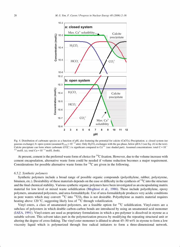
Fig. 4. Distribution of carbonate species as a function of pH, also featuring the potential for calcite (CaCO3) Precipitation. a: closed system (no
gaseous exchange); b: open system (assumed PCO2Z10K2 atm). Only H2CO3 exchanges with the gas phase, below pH 6.3 (see Eq. (4) in the text).
Calcite precipitate can form where carbonate ðCO2K3 Þ is significant compared to Ca2C (see shaded part). Assumed concentrations: total CZ10K
3.5 mol/L (a), total CaZ10K3 mol/L (both).
M.-S. Yim, F. Caron / Progress in Nuclear Energy 48 (2006) 2–3628
At present, cement is the preferred waste form of choice for 14C fixation. However, due to the volume increase with
cement encapsulation, alternative waste form could be needed if volume reduction becomes a major requirement.
Considerations for possible alternative waste forms for 14C are given in the following.
6.5.2. Synthetic polymers
Synthetic polymers include a broad range of possible organic compounds (polyethylene, rubber, polystyrene,
bitumen, etc.). Desirability of these materials depends on the ease or difficulty in the synthesis of 14C into the structure
and the final chemical stability. Various synthetic organic polymers have been investigated as an encapsulating matrix
material for low level or mixed waste solidification (Moghissi et al., 1986). These include polyethylene, epoxy
polymers, unsaturated polyesters, and urea-formaldehyde. Use of urea-formaldehyde produces very acidic conditions
in pore waters which may convert 14C into 14CO2 thus is not desirable. Polyethylene as matrix material requires
heating above 120 8C, suggesting likely loss of 14C through volatilization.
Vinyl esters, a class of unsaturated polyesters, are a feasible option for 14C solidification. Vinyl-esters are a
subclass of polyesters in which double carbon-carbon bonds are introduced by using an unsaturated acid monomer
(IAEA, 1991). Vinyl-esters are used as proprietary formulations in which a pre-polymer is dissolved in styrene as a
suitable solvent. This solvent takes part in the polymerization process by modifying the repeating structural unit or
altering the degree of cross-linking. The vinyl ester monomer is diluted to about 45–50 wt% in styrene to form a low
viscosity liquid which is polymerized through free radical initiators to form a three-dimensional network.

M.-S. Yim, F. Caron / Progress in Nuclear Energy 48 (2006) 2–36 29
The solidification of aqueous wastes with vinyl ester-styrene binder requires high shear-mixing to promote the
formation of a waste water-monomer emulsion (Moghissi et al., 1986). Advantages of vinyl-esters over other
polyesters are increased chemical resistance and better performance in the presence of water (IAEA, 1991). Vinyl
esters are less polar than polyesters and thus are less prone to the effects of water when cured by organic peroxides
(Franz et al., 1994).
A potential drawback with the use of styrene is the health and fire risk concerns during the handling of the material.
The long-term chemical and radiation stability of epoxy polymers and vinyl esters have not been fully demonstrated.
6.5.3. Glassy carbon
Glassy carbon (carbon allotropes) is an amorphous, gas-impermeable form of carbon with the appearance and
fracture characteristics of glass (McKee, 1973). Glassy carbon could potentially offer a unique approach to waste
disposal, as an intrinsic waste form because its durability does not depend upon maintaining a protective oxide film as
is required for glass. It may also be less susceptible to non-uniform modes of attack for the same reason.
Glassy carbon is manufactured by the solid-phase pyrolysis and heat treatment of certain thermosetting polymers,
typically phenolic resins. Glassy carbon has high temperature structural stability, chemical inertness, low gas
permeability, high thermal shock resistance, and is electrically conductive and thermally insulating. The formation of
glassy carbon involves the slow carbonation of nonmelting cross-linked polymers, with or without applied pressure.
In determining the morphology of the product, the chemical nature of the precursor is less important than the
condition of pyrolysis. Similar products can be prepared from a variety of starting materials, including phenolic
resins, acetone-furfural resin, etc. (McKee, 1973). For glassy carbon to be a candidate 14C waste form, a method
would have to be developed to incorporate 14C into one of these starting materials. This would generally involve a
reduction step to form a 14C hydrocarbon. Methods to convert from CO2 to CH4 and other hydrocarbons have been
identified (Calvin, et al., 1949), but the feasibility and practicality has not been fully assessed.
An alternative approach would be the capture of 14C from water after leaching from the ion-exchange resins into
phenolic ion-exchange resins. The efficiency of this process is expected to be high. The resulting phenolic resins can
be processed by slow pyrolysis above 1000 8C and be converted to glassy carbon. The maximum process temperature
is dependent on the required level of environmental durability and will be an important parameter for the feasibility of
using glassy carbon as a waste form.
Based on a process by Fitzer (Fitzer and Schafer, 1979), total carbon yield of the final product is estimated to be
between 80 and 85% with about 15–20% of initial carbon content expected to be released during the process.
Therefore, the issue of secondary waste generation needs to be addressed as well.
6.5.4. Silicon carbide
Silicon Carbide (formula SiC), which is known as carborundum (artificially-produced) or moissanite (naturally
occurring), is a very hard material, non-toxic, whose properties are close to those of the Carbon allotrope diamond.
Silicon makes bonds of the same tetrahedral arrangement as carbon-carbon bonds in diamond. The potential for
silicon carbide for encapsulating radioactive wastes is known (see e.g. Angelini et al., 1984). Silicon carbide is the
outer coating material for high-temperature gas cooled reactor fuels. Use of it as a coating for encapsulating
transmutation by-products following controlled burnups has been proposed (Rodriguez and Baxter, 2000). A
demonstration to include 14C wastes as part of the carbide (Si14C) has also been done (Torok et al., 1990). The latter
approach has the advantage that 14C is chemically bound to Si and it is part of the fabric of this stable mineral. Use of
silicon carbide requires that 14C is removed from the wastes (adding a purification step and potentially creating other
secondary wastes). The resulting carbide may include other impurities if spent resins are used as starting material. In
addition, costs and technology may not be ready for the large-scale transformation of 14C wastes into this waste form.
Silicon carbide is among new materials used in several expanding applications and this technology could become
economically feasible in the future.
6.5.5. Graphite
Graphite is a hexagonally crystallized allotrope of carbon that is widely used as a high-temperature refractory
because of its thermal stability. It is one of the materials most resistant to attack by the natural environment (Gray,
1980; Gray, 1982). Graphite, as in the case of glassy carbon, does not depend upon maintaining a protective oxide film
for its environmental durability. It is also less susceptible to non-uniform modes of attack for this same reason. In

M.-S. Yim, F. Caron / Progress in Nuclear Energy 48 (2006) 2–3630
the presence of a high-intensity gamma-radiation field, radiolysis of the water is enhanced by the presence of graphite.
But no measurable effect on the reaction rate of graphite was detected (Gray, 1982). Graphite is also very insoluble in
most acids and alkalis.
Processing of 14C waste into graphite waste form presents challenges due to the high temperature processing
required. Nonetheless, graphite has been proposed as a waste form for the fixation of 14C from the spent coated-
particle fuels from HTGR (Forsberg et al., 2003).
6.5.6. Use of special waste containers
The waste form/barrier includes those various components for disposal, i.e. the chemical form of the radionuclide,
the solidification matrix, and the container. To establish the necessary level of performance, the waste form must be
viewed as part of the entire waste disposal system, which includes components such as engineered structure, the
container, the geochemistry, and hydrogeology of the site and its climate.
In this regard, using a very highly durable waste container is a feasible alternative to immobilizing 14C. Although
high integrity containers (HICs) are currently employed for this purpose, the lifetime of HICs is expected to be
between 300 and 1000 years. Compared to the 5730 years of half-life of 14C, HICs’ lifetime is not long enough to
effectively control the potential hazard of 14C. Alternative approaches to HICs could include application of special
coating technologies to existing metallic waste containers or using a material of superior durability (e.g. graphite,
glassy carbon) for the container. Application of special coating over metallic surfaces appears feasible with the recent
advancement in coating technologies. The coating layers can include various ceramic oxide, metal carbide or nitride.
A major remaining challenge to the use of special waste containers is the development of a long-term data to justify
the extended lifetime of the containers for licensing purposes.
6.6. Management and disposal of 14C GTCC
Spent cartridge filters have recently emerged as a very important radioactive waste stream for 14C. They are
extensively used in PWRs to remove insoluble materials in the coolant. BWRs often use cartridge filters in the
processing of reactor cavity liquids and for spent fuel pool vacuuming (EPRI, 1996). As part of the nuclear industry’s
plant dose reduction efforts (NCRP, 1994; Yim and Ocken, 2001), submicron size filters have been adopted in nuclear
power plant systems. Experiences with these submicron size cartridge filters (Miller, 2000) showed that the
concentrations of 14C are much higher in these filters than what would normally be expected. The conventional
cartridge filters are currently disposed of after dewatering in poly HICs (without any immobilization). In some cases
the higher 14C concentration has resulted in the cartridge being ‘Greater-than-Class C’ by more than a factor of ten.
Such cartridges cannot be disposed of as low-level waste unless they are encapsulated and concentration averaging
includes the encapsulating agent.
This issue was discussed in a EPRI report (Yim, 2001) where cement and polymer waste forms were compared for the
purpose of concentration averaging. A cemented waste form provides a good encapsulation medium for 14C filters with
the benefits of reducing 14C release by the reduction in permeability/porosity, precipitation in the form of calcite with
reduced solubility, and with increased sorption capacity for 14C. As disadvantages with cement, worker radiation
exposure can be a concern depending upon the amount of cleanup efforts needed after the solidification process. A vinyl
ester styrene (VES) waste form provides a rigid, cross-linked, impermeable mass transport barrier for 14C leaching. It
also provides possibility of co-disposal of IX resins and filters. The potential concern for cracking with VES
encapsulation of waste can be minimized by adding bead resins and by controlling the polymerization reaction. NRC has
approved the VES method with addition of bead resins in the polymerization as encapsulation medium for filters. There is
less worker radiation exposure during cleanup operations. However, the VES solidification processes have to be closely
controlled. VES option is more expensive than cement. The shelf life of VES binder is rather short (about 6 months).
7. Conclusions and future directions
This paper reviewed the anthropogenic production of 14C, emissions potential from nuclear power plants, types of
wastes and waste forms, the potential of this radionuclide for migration in the environment, and other environmental
aspects of 14C. Our intention is to provide a bridge between the past and the future by summarizing existing scientific
understanding of 14C issues.
M.-S. Yim, F. Caron / Progress in Nuclear Energy 48 (2006) 2–36 31
Although 14C in the environment is not at a level to pose threat to public health, 14C features characteristics to be a
concern if appropriate measures are not enforced. The current inventory continues to grow annually due to nuclear
power production. The natural levels of 14C are close to the disposal limits (based on an individual 10K6 risk factor).
The inventory of 14C in the environment will increase as the release/disposal of 14C waste continues. If long-term
storage strategy is adopted, wastes will accumulate in storage facilities, along with the associated potential for
emissions. This may points to the need to build engineered controls for 14C. Should an effective disposal strategy be
implemented, issues of capacity, costs, pre-processing, waste forms, containment, etc., will need to be addressed. The
balancing act, at present, is the balance between priorities, costs, and benefits to society and the environment.
Some general directions and/or issues that need attention to better manage 14C were identified in this paper. These
are summarized below.
The data to characterize 14C production in fuel, coolant/moderator are old in particular with LWRs. The situation
appears to be better for HWRs. Some of the estimates from Table 3 originate from surveys from the mid-1970 s,
particularly for the production in fuel. A substantial amount of data for HWRs is of proprietary nature and cannot be
disclosed at present. This practice may need to change. Either obtaining new data or verifying the accuracy of the old
data would be necessary for reliable risk management and for public support.
It would be necessary to develop and/or share databases to show recent trends in 14C emissions (from nuclear
reactors and waste storage sites). Any progress in using relevant engineering approaches to reduce 14C emissions
should be noted and shared. The authors believe that recent trends and engineered controls have progressed and it is
important to share these findings to the Scientific Community and the Public.
Additional data to better understand the behavior of 14C in the environment is needed to improve the scientific
basis. These data needs may become practically important in the future, depending upon the evolution of the
regulatory and public perspective on LLW site performance assessment. The data needs include (1) Quantitative data
on isotope mixing-for the inorganic components of soils, (2) Quantitative data on conversion from inorganic to
organic C (and vice-versa as applicable); (3) Groundwater/gas transfer factor for 14C using field-based data covering
the field scale for waste management areas, and; (4) Updated data for terrestrial transport of 14C for relevant
environmental assessments covering the height effect of 14C transfer for different plants/vegetation.
With regards to modeling the behavior of 14C in the waste, two areas of research needs are noted. These are: (1)
Leaching studies on ion exchange resins, especially on the effect of biodegradation. Ion exchange resins are a major
source of 14C, and although leaching models and protocols have been developed, specific mechanisms need to be
better characterized (effects of ion competition, the effect of bacterial decay, etc.). (2) Given the widespread use of Kd-
based leach modeling for a wide variety of 14C wastes (resins, filters, and various solid wastes), validating the current
practice along with development of appropriate data could be necessary. On a practical standpoint, leaching studies,
Kd’s, effective diffusivities can be readily incorporated in prediction models. The drawback is that these parameters
lump together several geochemical processes together. It is important to identify these limitations, such that the actual
mechanisms are known and they are controlled during the period of interest.
One major related issue is the handling and disposal of ion exchange resins: If long-term storage of resins is
necessary, what should be planned, and what type of processing should be done, if at all? Would it be necessary to
segregate and re-route the wastes in dedicated facilities? Included in this should be cost/benefit analysis of separating
the 14C from resins (to place 14C in stable chemical form such as carbonate minerals, separated from extracted resins),
resin encapsulation in stable materials, or other technologies. The option of 14C separation and incorporation into
cement waste form needs to be compared with the alternatives using new waste form materials.
Developing knowledge on new 14C waste forms deserves further consideration if the affected LLW volume
becomes a concern. The resulting new waste forms would be useful for the disposal of other major long-lived
radionucldies. Thus use of a specific waste form and its pros and cons should be evaluated not only for 14C but also for
other major long-lived radionuclides present in the waste. New technologies should be considered in the future (e.g.
extraction, encapsulation, incorporation into new materials), especially if they are becoming available and
economically feasible.
Acknowledgements
The authors are grateful for the valuable comments provided by the anonymous reviewers and Dr Dade Moeller of
Harvard University.

M.-S. Yim, F. Caron / Progress in Nuclear Energy 48 (2006) 2–3632
References
ACRP, 1995. The management of Carbon-14 in Canadian Nuclear Facilities, ACRP-14. Advisory Committee on Radiological Protection
(committee of the Atomic Energy Control Board of Canada), Ottawa, Ontario.
AECL, 1994. Environmental Impact Statement on the concept for disposal of Canada’s nuclear fuel waste, AECL-10711, COG-93-1. Atomic
Energy of Canada Limited, Chalk River, Ont.
AECL, 2002. New Opportunities for Atomic Energy of Canada Limited (AECL). http://www.cna.ca/english/speeches.asp.
Allard, B., 1985. Radionuclide sorption on concrete. Nagra NTB 85-21, Nagra, Baden/Swtizerland.
Allard, B., Torstenfelt, B., Anderson, K., 1981. Sorption studies of H14CO3 on some geologic media and concrete. Scientific Basis for Nuclear
Waste management III, MRS Symposium Proceedings 3, 465–472.
Amiro, B.D., 1995. Some simplified radiological dose estimates using isotopic dilution in the biosphere for the disposal of Canada’s nuclear fuel
waste. Atomic Energy of Canada Limited Technical Record, TR-693, COG-95-286, Chalk River, Ontario.
Angelini, P., DeVore, C.E., Lackey, W.J., Blanco, R.E., Stinson, D.P., 1984. Method of Deposition of Silicon Carbide Layers on Substrates and
Product. U.S. Patent No. 4,459,338.
Bayliss, S., Ewart, F.T., Howse, R.M., Smith-Briggs, J.L., Thomason, H.P., Wilmott, H.A., 1988. The solubility and sorption of Lead-210 and
Carbon-14 in a near-field environment. Scientific Basis for Nuclear Waste Management XI, MRS Symposium Process 112, 33–42.
Beyeler, W.E., Brown, T.J., Hareland, W.A., Conrad, S., Olague, N., Brosseau, D., Kalinina, E., Gallegos, D.P., Davis, P.A., 1999. Residual
Radioactive Contamination from Decommissioning: Parameter Analysis. NUREG/CR-5512, SAND99-2148, Vol. 3, Sandia National
Laboratories.
Bio-Rad, 1987. Guide to ion exchange, Catalog Number 140-9997, Richmond, CA: Bio-Rad Laboratories.
Bonka, K.H., Brussermann, G., Schwarz, 1974. Umweitbelatung durch Radiokolenstolf aus Kerntechnichen Analgen, Reactortagung, Berlin.
Boss, C.R., Allsop, P.J., 1995. Radioactive Effluents from CANDU 6 Reactors During Normal Operations, AECL-11506. Atomic Energy of Canada
Limited, Chalk River, Ont..
Braun, H., Gutowski, H., Bonka, H., Grundlen D., 1983. Plant for Retention of 14C in Reprocessing Plants for LWR Fuel Elements, in Proc. 17th
DOE Nuclear Air Cleaning Conference, CONF-820833, pp. 381–399.
Brookins, D.G., 1988. Eh-pH Diagrams for Geochemistry. Springer, Berlin.
Buckley, L.P., Woods, B.L., Ward, W.J., 1985. A method for removing Carbon-14 from particulate, ion exchange resins. Canadian Patent No. CA
1250378, Canadian Intellectual Property Office, http://patents1.ic.gc.ca.
Buhmann, D., Nies, A., Storck, R., 1991. Systemanalyse Mischkonzept, Technischer Anhang 7. KWA Nr.5702A. GSF, Braunschweig, Federal
Republic of Germany.
Bush, R.P., Smith, G.M., White, I.F., 1984. Carbon-14 Waste Management, EUR-8749 EN. Commission of the European Communities,
Luxembourg.
Butow, E., et al., 1985. Modellrechnungen zur Ausbreitung von Radionukliden im Deckgebirge. Projekt Sicherheitsstudien Entsorgung (PSE).
Fachband, 18, BFT, Berlin.
Calvin, M., Heidelberger, C., Reid, J.C., Tolbert, B.M., Yankwich, P.F., 1949. Isotopic Carbon. Wiley, NY.
Caron, F., 1996. Overview and dynamics of organic carbon in a low-level radioactive waste degradation experiment. In: Waste Management’96,
Eds., Post, R.G., Wacksno M.E. AECL report RC-M-20. Tucson, AZ: WM’97 Symposia Inc.
Caron, F., Milton, G.M., 1998. Preface to papers on carbon cycling in mid-latitudes. Applied Geochemistry 13, 1–2.
Caron, F., Torok, J., 2000. Ion exchange resin degradation and Carbon-14 emission control in CANDU moderator system. Eight International
Conference of Water Chemistry of Nuclear Reactor Systems, Bournemouth UK, Oct. 22–26, 2000. Water chemistry of nuclear reactor systems
8, British Nuclear Energy Society, Thomas Telford, ISBN 0-7277-2958-6, pp. 241–243.
Caron, F., Wilkinson, S.R., Torok, J., Haas, M.K., Selander, W.N., 1994. CO2 transport through the capillary fringe in sand. Waste Management 14,
421–434.
Caron, F., Manni, G., Workman, W.J.G., Haas, M.K., 1998a. Soil CO2 Gas-groundwater Exchange and Migration Near Waste Management Area C,
Chalk River, Ontario, RC-2121, COG 98 253-I. Atomic Energy of Canada Limited, Chalk River Laboratories, Chalk River, Ont..
Caron, F., Sutton, J., Recoskie, C.L., Haas, M.K., scoping, A., 1998b. A Scoping Study of C-14 Gaseous Emissions from Waste Management Area
C, Chalk River Laboratories. RC-2113. Atomic Energy of Canada Limited, Chalk River, Ontario.
Caron, F., Manni, G., Workman, W.J.G., 1998c. A large-scale laboratory experiment to determine the mass transfer of CO2 from a sandy soil to
moving groundwater. Journal of Geochemistry Explor. 64, 111–125.
Chang, F.H., Krochmalnek, L.S., 1992. Method for separating Carbon-14 from particulate ion-exchange resins. Canadian Intellectual Property
Office, Application CA 2023729. http://patents1.ic.gc.ca.
Chang, F.H., Krochmalnek, L.S., Vogy, H.K., Sood, S.K., Bartoszek, F.E., Robins, J.R., Woodall, K.B., 1990. Canadian Intellectual Property
Office, Application CA 2061307. http://patents1.ic.gc.ca.
Choppin, G.R., Liljenzin, J.-O., 2002. Radiochemistry and Nuclear Chemistry, third ed. Butterworth-Heinemann, Woburn, MA.
Cline, J.E., Noyce, J.R., Coe, L.F., Wright, K.W., 1985. Assay of Long-Lived Radionuclides in Low-Level Wastes from Power Reactors.
NUREG/CR-4101. U.S. Nuclear Regulatory Commission.
Dames and Moore, 1995. Waste Inventory Revision 3, North Carolina Low-Level Radioactive Waste Disposal Facility Project, DM/DR-002,
prepared for Chem-Nuclear Systems, Inc.
Dames and Moore, 1995. Literature Review of Sorption Coefficients for Radionuclides in Cementitious Environments, Revision 1, Prepared for
Chem-Nuclear Systems, Inc.

M.-S. Yim, F. Caron / Progress in Nuclear Energy 48 (2006) 2–36 33
Dayal, R., 1995a. The Role of Cementitious Materials in Carbon-14 Waste Disposal, Proceedings of Conference, Radioactive Waste Management
and Environmental Remediation, American Society of Mechanical Engineers 1995.
Dayal, R., 1995b. The Role of Cementitious Materials in Carbon-14 Waste Disposal, Proceedings of the 5th International Conference on
Radioactive Waste Management and Environmental Remediation. American Society of Mechanical Engineers pp. 1009–1013.
Dayal, R., Reardon, E.J., 1992. Cement-based engineered barriers for Carbon-14 isolation. Waste Management 12, 189–200.
Dayal, R., Klein, R., 1987. Evaluation of Cement-Based Backfill Materials. Report No. 87-223-K, Ontario Hydro Research Division, Toronto,
Canada.
Dias, S.A., Shapka, W., 2000. Supercritical carbon dioxide extraction of contaminants from ion exchange resins. Canadian Patent CA 2348521,
Canadian Intellectual Property Office, http://patents1.ic.gc.ca.
Dolinar, G.M., Rowat, J.H., Stephens, M.E., Lange, B.A., Killey, R.W.D., Rattan, D.S., Wilkinson, S.R., Walker, J.R., Jategaonkar, R.P., 1996.
Preliminary Safety Analysis Report (PSAR) for the Intrusion Resistant Undergound Structure (IRUS), AECL-MISC-295 (Rev. 4). Atomic
Energy of Canada Limited, Chalk River Laboratories, Chalk River, Ont..
DuBourg, M., 1995. The Carbon 14 Cycle, IAEA-TECDOC-901, pp233-237, Graphite Moderator Lifecycle Behaviour, Proceedings of a specialist
meeting, Bath, UK, 24–27 September, 1995, IAEA.
Ehalt, D.H., 1973. Methane in the Atmosphere. In: Woodwell, G.M., Pecan, E.V. (Eds.), Carbon and the Biosphere, Proceedings of the 24th
Brookhaven Symposium in Biology, Upton, N.Y., May 16–18 1972 AEC Symposium Series, CONF-720510. U.S. Atomic Energy Commission,
Washington, D.C..
Ehrig, H.-J., 1983. Quality and quantity of sanitary landfill leachate. Waste Management and Research 1, 53–68.
EPRI, 1996. Level Waste Characterization Guidelines. Electric Power Research Institute.
Evenden, W.G., Sheppard, S.C., Killey, R.W.D., 1998. Carbon-14 and tritium in plants of a wetland containing contaminated groundwater. Applied
Geochemistry 13, 17–21.
Ewart, F.T., Pugh, S.Y.R., Wisbey, S.J., Woodwark, D.R., 1989. Chemical and Microbiological Effects in the Near-Field-Current Status 1989,
NSS/G111, Nirex, Harwell/UK.
Findikakis, A.N., Papelis, C., Halvakadis, C.P., Leckie, J.O., 1988. Modelling gas production in managed sanitary landfills. Waste Management and
Research 6, 115–123.
Fitzer, E., Schafer, W., 1979. The effect of crosslinking on the formation of glasslike carbons from thermosetting resins. Carbon 8, 353–364.
Forsberg, C.W., Del Cul, G.D., Spencer, B.B., Collins, E.D., 2003. A New Repository Waste Form: Graphite–Carbon High-Level Waste. Proc.
2003 International HLW Management Conference, Las Vegas, NVm March 30–April 2.
Fowler, T.W., Nelson, C.B., 1981. Health Impact Assessment of Carbon-14 Emissions from Normal Operations of Uranium Fuel Cycle Facilities.
EPA 520/5-80-004. Environmental Protection Agency, Washington, DC.
Franz, E., Fuhrmann, M., Bowerman, B., Bates, S., Peters, R., 1994. Proposed Waste Form Performance Criteria and Testing Methods for Low-
Level Mixed Waste. BNL-52436, DOE/MWIP-30, Brookhaven National Laboratory.
Gascoyne, M., 1992. Concentrations of C in groundwater for the geosphere model. Atomic Energy of Canada Limited Technical Record, TR-567,
COG-92-27. Chalk River, Ontario.
Government of Canada, 2002. An act respecting the long-term management of nuclear fuel waste, House of Commons of Canada, Bill C-27,
Ottawa, Ontario.
Glasbergen, P., Englend-Boroviec, G., Nijhoff-Pan, I., Slot, A.F.M., 1989. Transport van radionukliden door de ondergrond. RIVM (Rijksinst.
Milieuonderzoek), Bilthoven, Rep. 728513010.
Gray, W.J., 1980. Reaction of graphite with water and its implications for radioactive waste storage. Radioactive Waste Management 1 (1), 105–
109.
Gray, W.J., 1982. A study of the oxidation of graphite in liquid water for radioactive waste storage applications. Radioactive Waste Management
and the Nuclear Fuel Cycle 3 (2), 137–149.
Gruhlke, J.M., Neiheisel, J., Battist, L., 1986. Estimates of the Quantities, Form and Transport of Carbon-14 in Low Level Radioactive Waste. EPA
520/1-86-019, US Environmental Protection Agency.
Guiroy, J.-J., 1995. Graphite Waste Incineration in a Fluidized Bed, IAEA-TECDOC-901, pp. 193–203, Graphite Moderator Lifecycle Behaviour,
Proceedings of a specialist meeting, Bath, UK, 24–27, 1995, IAEA.
Guvanasen, V.M., 1985. Preliminary Assessment for the Disposal of Intermediate-Level Reactor Waste, AECL TR-293. Atomic Energy Canada
Ltd, Pinawa, Man..
Hietanen, R.T., Kaakkola, Miettinen, J., 1985. Sorption of cesium, strontium, iodine, and carbon in concrete and sand. Scientific Basis for Nuclear
Waste Management VIII, MRS Symposium Process 44, 891–898.
Healy, J.W., 1971. Surface Contamination: Decision Levels. LA-4558-MS. Los Alamos National Laboratories.
Holtorp, J., 1996. A Strategy for the Management of Carbon-14 at OHN’s Nuclear Facilities, N-REP-03467-0138 Rev 0. Ontario Hydro Nuclear,
Toronto, Ont..
IAEA (International Atomic Energy Agency), 1991. Conditioning of Alpha Bearing Waste. Technical Report Series No. 326, Vienna.
ICRP, 1968. Report of Committee IV on Evaluation of Radiation Doses to Body Tissues from Internal Contamination due to Occupational
Exposures. ICRP Publication 10. Pergamon Press, New York, NY.
Impell Corporation, 1985. Radionuclide Correlations in Low-Level Radwastes. EPRI NP-4-37, Electric Power Research Institute.
IUPAC, 1984. Element by element review of their atomic weights. Pure and Applied Chemistry 56, 695–768.
Jefferies, N., 1990. The Evolution of Carbon-14 and Tritium Containing Gases in a Radioactive Waste Repository. Report NSS/R198, Nirex Ltd.,
Harwell, UK.
Jenkinson, Rayner, 1979. Decomposition in terrestrial ecosystems. In: Swift, M.J., Heal, O.W., Anderson, J.M. (Eds.), Vol. Studies in Ecology, vol.
5. University of California Press, Berkely, CA (USA), pp. 119–219 (Chapter 4 and 5).

M.-S. Yim, F. Caron / Progress in Nuclear Energy 48 (2006) 2–3634
Johnston, H.M., 1990. Laboratory studies of the transport of Carbon-14 in Unsaturated Geologic Materials. University of Waterloo. Also available
as Ontario Hydro Report 90-142-K, Toronto, ON.
Killey, R.W.D., Rao, R.R., Eyvindson, S., 1998. Radiocarbon speciation and distribution in an aquifer plume and groundwater discharge area,
Chalk River, Ontario. Applied Geochemistry 13, 3–16.
King, K.J., Kramer, S.J., Repta, C., 1998. Measurements of CANDU 14C Emissions from Tree Rings, COG-98-251-I. Atomic Energy of Canada
Limited, Chalk River, Ont..
Kitabata, T., Sakurai, N., 1988. Experience of water chemistry control in Fugen NWR. Second International Topical Meeting on Nuclear Power
Plant Thermal Hydraulics and Operations. 11-47-11-55.
Kotzer, T.G., Watson, W.L., 1999. Spatial and Temporal Distribution of C14 in Cellulose in Tree Rings in Central and Eastern Canada: Comparison
with Long-term Atmospheric and Environmental Data, AECL-12002. Atomic Energy of Canada Limited, Chalk River, Ont..
Krupka, K.M., Serne, R.J., 1998. Effects on Radionuclide Concentrations by Cement/Ground-Water Interactions in Support of Performance
Assessment of Low-Level radioactive Waste Disposal Facilities. NUREG/CR-6377, PNNL-11408, U.S. Nuclear Regulatory Commission.
Krupka, K.M., Serne, R.J., Jenne, E.A., 1995. Geochemical Effects on the Behavior of Low-level Waste Radionuclides in Soil/Groundwater
Environments. 17th. U.S. DOE LLW Management conference, Phoenix, AZ, December 12–14.
Kunz, C., 1985. Carbon-14 discharge at three light-water reactors. Health Physics 49, 25–35.
Lever, D.A., Woodwark, D.R., 1989. Radionuclide Transport by Groundwater Flow Through the Geosphere-Current Status 1989. NSS/G113. Nirex
Ltd, Harwell, UK.
Liepins, L.Z., Thomas, K.W., 1988. Survey of 14C literature relevant to a geologic nuclear waste repository. Rad. Waste Management Nuclear Fuel
Cycle 10, 357–380.
Link, S.O., King, K.J., Benz, M.L., Evenden, W.G., Robertson, D.E., 1999. Environmental Dynamics of Carbon-14 Near a Low-Level Radioactive
Waste Burial Ground. U.S. Nuclear Regulatory Commission, Washington, DC.
Looney, B.B., Grant, M.W., King, C.M., 1987. Estimation of Geochemical Parameters for Assessing Subsurface Transport at the Savannah River
Plant. DPST-85-904. Savannah River Laboratory, Aiken, SC.
Martin, J.E., 1986. Carbon-14 in low-level radioactive waste from two nuclear power plants. Health Physics 50, 57–64.
Matsumoto, J., Banba, T., Muraoka, S., 1995. Adsorption of Carbon-14 on mortar. Mater Research Society Symposium Process 353, 1029–1035.
McKee, D.W., 1973. Carbon and graphite science. Annual Review of Materials Science 3, 195–231.
McKinley, I.G., Hadermann, J., 1985. Radionuclide Sorption Database for Swiss Safety Assessment. NTB 84-40, NAGRA (National Coop. For
Storage of Radioactive Waste), Baden.
McKinley, I.G., Sholtis, A., 1993. A comparison of radionuclide sorption databases used in recent performance assessments. Journal of
Contaminant Hydrology 13, 347–363.
McNeely, R., 1994. Long-term environmental monitoring of 14C levels in the Ottawa region. Environment International 20, 675–679.
Miller, C.C., 2000. Personal Communications. Pacific Gas and Electric Company, Avila Beach, CA.
Milton, G.M., 1993. Workshop on the Environmental Behaviour of C-14, RC-1009; COG-93-209. Atomic Energy of Canada, Ltd, Chalk River,
Ont..
Milton, G.M., 1996. Workshop on Carbon cycling in Mid-latitudes: Field and tracer studies. RC-1570. Atomic Energy of Canada Limited, Chalk
River Laboratories, Chalk River, Ont..
Milton, G.M., Brown, R.M., Repta, C.J.W., Selkirk, C.J., 1996. Atmospherically Dispersed Radiocarbon at the Chalk River Laboratories, AECL-
11421. Atomic Energy of Canada Limited, Chalk River Laboratories, Chalk River, Ont.
Milton, G.M., King, K.J., Sutton, J., Enright, S., 1998. Tracer studies of carbon source utilization in a wetland on the Canadian shield. Applied
Geochemistry 13, 23–30.
Moghissi, A.A., Godbee, H.W., Hobart, S.A., 1986. Radioactive Waste Technology. The American Society of Mechanical Engineers.
Morel, F.M.M., Herig, J.G., 2000. Principles and Applications of Aquatic Chemistry. Wiley-Interscience, New York.
Mori, S., Akatsuka, H., Suzuki, M., 2001. Carbon and oxygen isotope separation by plasma chemical reactions in carbon monoxide glow discharge.
Journal of Nuclear Science and Technology 38 (109), 850–858.
Nacarrow, D.J., Summerling, T.J., Ashton, J., 1988. Preliminary Radiological Assessments of Low-Level Waste Repositories. DOE/RW/88.084,
Department of Environment, London, United Kingdom.
NAGRA (Swiss National Cooperation for Storage of Radioactive Waste). 1985. Project Gewahr, Project Summary Report, NGB 85-09, 8 vol.,
NAGRA, Baden, Switzerland.
NAGRA (Swiss National Cooperation for Storage of Radioactive Waste). 1988. Sediment Study-Intermediate Report, NGB 88-25E (English
executive summary), NAGRA, Baden, Switzerland.
NCRP, 1994. Dose Control at Nuclear Power Plants. NCRP Report No. 120, National Council on Radiation Protection and Measurements,
Bethesda, MD.
NCRP, 1985. Carbon-14 in the Environment. NCRP Report 81, National Council on Radiation Protection and Measurements, Bethesda, MD.
Noshita, K., Nishi, T., Matsuda, M., Izumida, T., 1996. Sorption Mechanism of Carbon-14 by Hardened Cement Paste. Scientific Basis for Nuclear
Waste Management Mat. Res. Soc. Symp. Proc., vol. 412. Materials Research Society.
NWMO, 2003. Nuclear Waste Management Organization, http://www.nwmo.ca/.
Nydal, R., Loveseth, K., Syrstad, O., 1971. Bomb 14C in the human population. Nature 232, 418.
Peltonen, E., Vuori, S., Anttilla, M., Hillebrand, K., Meling, K., Rasilainen, K., Salminen, P., Suolanen, V., Winberg, M., 1985. Safety Analysis of
Disposal of Spent Nuclear Fuel-Normal and Disturbed Evolution Scenarios. Report YJT-85-22, Nuclear Waste Commission of Finnish Power
Companies, Helsinki, Finland.
Pirt, S.J., 1978. Aerobic and anaerobic microbial digestion in waste reclamation. Journal of Applied Chemistry Biotechnology 28, 232–236.
M.-S. Yim, F. Caron / Progress in Nuclear Energy 48 (2006) 2–36 35
Rao, R.R., 1997. Tritium and Carbon-14 in CANDU Reactors: Comparison of their Production and Release Rates with Those from Other Types of
Reactors, COG-97-463-I. Atomic Energy of Canada Limited, Chalk River, Ont..
Rao, R.R., Killey, R.W.D., 1994. Quantitative separation and determination of inorganic and organic forms of total carbon and radiocarbon in
natural waters and application at a radioactive waste management site. Radiochima Acta 65, 63–74.
Rautenstrauch, K.R., Smith, A.J., Andrews, R., 2003. Technical Basis Document No. 12: Biosphere Transport, Revision 1, Bechtel SAIC Company,
LLC, Las Vegas, Nevada.
Rodriguez, C., Baxter, A., 2000. Transmutation of nuclear waste using gas-cooled reactor technologies. 8th International Conference on Nuclear
Engineering (ICONE 8), Apr. 2–6, 2000, Baltimore, MD.
Romanoff, M., 1957. Underground corrosion. National Bureau of Standards Circular, 579.
Rosset, R., Desbarres, J., 1993. Proprietes redox de 14C, Report Submitted to Electricite De France.
Sakurai, T., Yokoyama, A., 2000. Decomposition of carbon dioxide, carbon monoxide and gaseous water by microwave discharge. Journal of
Nuclear Science and Technology 37 (9), 814–820.
Scheele, R.D., Burger, L.L., 1982. Selection of Carbon-14 Fixation Form. PNL-4447, Pacific Northwest Laboratory.
Serne, R.J., Lokken, R.O., Criscenti, L.J., 1992. Characterization of grouted low-level waste to support performance assessment. Waste
Management 12, 271–287.
Sheppard, M.I., Thibault, D.H., 1990. Default soil solid/liquid partition coefficients, Kds, for four major soil types: a compendium. Health Physics
59, 471–482.
Sheppard, M.I., Sheppard, S.C., Amiro, B.D., Schwartz, W.J., Hawkins, J.L., Thibault, D.H., 1990. Soil-to-plant transfer factor of carbon-14 for
environmental assessment of radioactive waste repositories. EPRI NP-6946, Electric Power Research Institute, Palo Alto, CA.
Sheppard, S.C., Amiro, B.D., Sheppard, M.I., Stephenson, M., Zach, R., Bird, G.A., 1994. Carbon-14 in the biosphere: modelling and supporting
research for the canadian nuclear fuel waste management program. Waste Management 14, 445–456.
Simister, C., Caron, F., Gedye, R., in press. Determination of the thermal degradation rate of polystyrene–divinyl benzene ion exchange resins in
ultra-pure water at ambient and service temperature. J. Radioanal. Nucl. Chem.
Striegl, R.G., Healy, R.W., 1990. Transport of 14CO2 in Unsaturated Glacial and Eolian Sediments. In: Melchior, D.C., Bassett, R.L. (Eds.),
Chemical Modeling of Aqueous Systems II, no. ACS Symp. Ser. 416. ACS, Washington DC.
Stroes-Gascoyne, S., West, J.M., 1994. Microbial Issues Pertaining to the Canadian Concept for the Disposal of Nuclear Fuel Waste, AECL-10808;
COG-93-54. Atomic Energy of Canada, Ltd., Pinawa, Man. (Canada).
Su, S.-I., Yim, M.-S., 2000. Analysis of radionuclide release from spent ion-exchange resins. Nuclear Technology 130, 71–88.
Suess, H.E., 1955. Radiation concentration in modern wood. Science 122 (3166), 414–417.
Sullivan, T.M., Suen, C.J., 1989. Low-Level Waste Shallow Land Disposal Source Term Model: Data Input Guide. NUREG/CR-5387, BNL-
NUREG-52206, Brookhaven National Laboratory, Upton, NY.
Swift, M.J., Heal, O.W., Anderson, J.M., 1979. Decomposition in Terrestrial Ecosystems, Vol. Studies in Ecology, vol. 5. University of California
Press, Berkely, CA (USA) (pp. 119–219, Chapters 4 and 5).
Takeshita, K., Nakano, Y., Shimizu, M., Fujii, Y., 2002. Recovery of 14C from graphite moderator of gas-cooled reactor. Journal of Nuclear Science
and Technology 39 (11), 1207–1212.
Thorstenson, D.C., Weeks, E.P., Haas, H., Fisher, D.W., 1983. Distribution of gaseous 12CO2, 13CO2, and 14CO2 in the sub-soil unsaturated zone of
the western US great plains. Radiocarbon 25, 315–346.
Till, J.E., Meyer, H.R., 1983. Radiological Assessment, A Textbook on Environmental Dose Analysis. NUREG/CR-3332, ORNL-5968, U.S.
Nuclear Regulatory Commission.
Torok, J., Caron, F., 2000. Carbon-14 chemistry in CANDU moderator system. 21st Canadian Nuclear Society meeting, Toronto, ON, June 11–14,
2000. Canadian Nuclear Society, Toronto, ON.
Torok, J., Lovasic, Z., Haas, M.K. 1990. Unpublished internal AECL report.
UNSCEAR, 2000. Limiting. EPA-520/1-88-020, Office of Radiation Programs, Environmental Protection Agency, Washington, DC.
US EPA, 1988. Limiting Values of Radionuclide Intake and Air Concentration and Dose Conversion Factors for Inhalation, Submersion, and
Ingestion. EPA-520/1-88-020, Office of Radiation Programs, Environmental Protection Agency, Washington, DC.
US EPA, 1988. Low-Level and NARM Radioactive Wastes, Draft Environmental Impact Statement for Proposed Rules, Volume 1, Background
Information Document, EPA 520/1-87-012-1, Office of Radiation Programs, Environmental Protection Agency, Washington, DC.
US EPA. 1994. Code of Federal Regulations, Title 40, Chapter 1, Part 191, Environmental Radiation Protection Standards for Management and
Disposal of Spent Nuclear Fuel, High-Level and Transuranic Radioactive Wastes. Federal Register.
US EPA. 2001. 40 CFR Part. 197. Public Health and Environmental Radiation Protection Standards for Yucca Mountain. Nevada, June 13.
U. S. NRC. 1981. Draft Environmental Impact Statement on 10CFR Part 61. NUREG-0782, Vol. 4, U.S. Nuclear Regulatory Commission.
US NRC., 1982. Code of Federal Regulations, Title 10, Chapter 1, Part 61, Licensing Requirements for Land Disposal of Radioactive Waste.
Federal Register. 47, 57446.
US NRC, 1993. Source Term Implementation for Initial Performance Assessment Calculation. Technical Review of Performance Assessment
Modeling Strategy, Rockville, MD, July 12–13, Nuclear Regulatory Commission.
US NRC, 1994. Overview of NRC Staff LLWPA Modeling Efforts. Low-Level Waste Performance Assessment Workshop, Rockville, MD,
November 17, Nuclear Regulatory Commission.
US NRC. 2001. 10 CFR Part. 63, Disposal of High-Level Radioactive Waste in a Geologic Repository at Yucca Mountain. Nevada, November, 2.
Van Konynenburg, R.A., 1994. Behavior of Carbon-14 in waste packages for spent fuel in a tuff repository. Waste Management 14, 363–383.
Vance, J.N., Cline, J.E., Robertson, D.E., 1995. Characterization of Carbon-14 generated by the Nuclear Power industry, TR-105715. EPRI, Palo
Alto, California, Electric Power Research Institute.

M.-S. Yim, F. Caron / Progress in Nuclear Energy 48 (2006) 2–3636
Vieno, T., Nordman, H., 1991. Safety Analysis of the VLJ Repository. Report YJT-91-12, Nuclear Waste Commission of Finnish Power
Companies, Helsinki, Finland.
Wickham, A.J., Marsden, B.J., Sellers, R.M., Pilkington N.J., 1995. Graphite Core Stability During Care and Maintenance and Safe Storage, IAEA-
TECDOC-901, pp. 225–232, Graphite Moderator Lifecycle Behaviour, Proceedings of a specialist meeting, Bath, UK, 24–27 September, 1995,
IAEA.
Wickham, A.J., Neighbour, G.B., Dubourg, 2001. The Uncertain Future for Nuclear Graphite Disposal: Crisis or Opportunity? Proceedings of
Technical Committee Meeting, Nuclear Graphite Waste Management. Manchester, UK, October 18–20, 1999, International Atomic Energy
Agency, Vienna, Austria.
Wilborgh, M., Lindgree, M., 1987. SKA Progress Report, SFR 87-09, SKB, Stockholm, Sweden.
Wise, M., 2001. Management of UKAEA Graphite Liabilities, Proceedings of Technical Committee Meeting, Nuclear Graphite Waste
Management. Manchester, UK, October 18–20, 1999, International Atomic Energy Agency, Vienna, Austria.
WNA, 2004. World Nuclear Association web site, http://www.world-nuclear.org/, accessed October to December 2004.
Wood, C.J., 1995. Dose Reduction Methods. In: Maletskos, C.J. (Ed.), Dose Reduction Methods: Chemical and Physical, in Radiation Protection at
Nuclear Reactors. Medical Physics Publishing, Madison, WI.
Yim, M.-S., 1994. Gas-Phase Release of Radionuclides from Low-Level Radioactive Waste Disposal Facilities. Sc.D. Thesis, Harvard University
School of Public Health, Boston, MA.
Yim, M.-S., 1998. Evaluation of Waste Forms for Immobilization of 14C and 129I. EPRI TR-110096, Final Report, Electric Power Research
Institute.
Yim, M.-S., 2001. Investigation of Alternative Waste Forms for GTCC 14C Filters. Report 1003066, EPRI, Palo Alto, CA.
Yim, M.-S., Simonson, S.A., 1999. Carbon-14 in Low-Level Waste. TR-107957, EPRI, Palo Alto, CA.
Yim, M.-S., Simonson, S.A., 2000. Performance assessment models for low level radioactive waste disposal facilities: a review. Progress in Nuclear
Energy 36 (1), 1–38.
Yim, M.-S., Ocken, H., 2001. Radiation dose management in nuclear power plants. Progress in Nuclear Energy 39 (1), 31–51.
Yim, M.-S., Simonson, S.A., Sullivan, T.M., 1996. Investigation of C-14 release from a generic LLW disposal facility. Nuclear Technology 114 (2),
254–271.