Embed Size (px)
Citation preview
Page 12
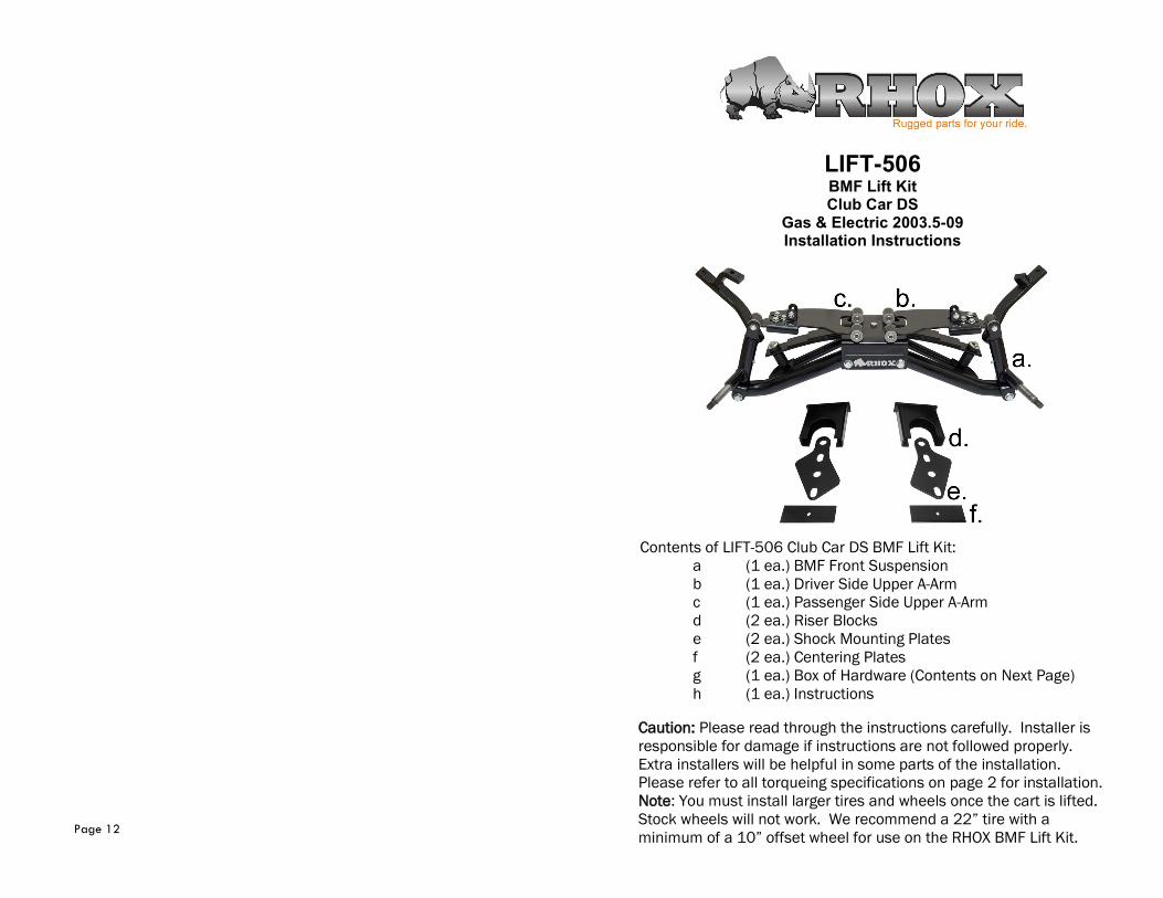
Contents of LIFT-506 Club Car DS BMF Lift Kit:
a (1 ea.) BMF Front Suspension
b (1 ea.) Driver Side Upper A-Arm
c (1 ea.) Passenger Side Upper A-Arm
d (2 ea.) Riser Blocks
e (2 ea.) Shock Mounting Plates
f (2 ea.) Centering Plates
g (1 ea.) Box of Hardware (Contents on Next Page)
h (1 ea.) Instructions
Caution: Please read through the instructions carefully. Installer is
responsible for damage if instructions are not followed properly.
Extra installers will be helpful in some parts of the installation.
Please refer to all torqueing specifications on page 2 for installation.
Note: You must install larger tires and wheels once the cart is lifted.
Stock wheels will not work. We recommend a 22” tire with a
minimum of a 10” offset wheel for use on the RHOX BMF Lift Kit.
LIFT-506 BMF Lift Kit Club Car DS
Gas & Electric 2003.5-09 Installation Instructions
Page 2
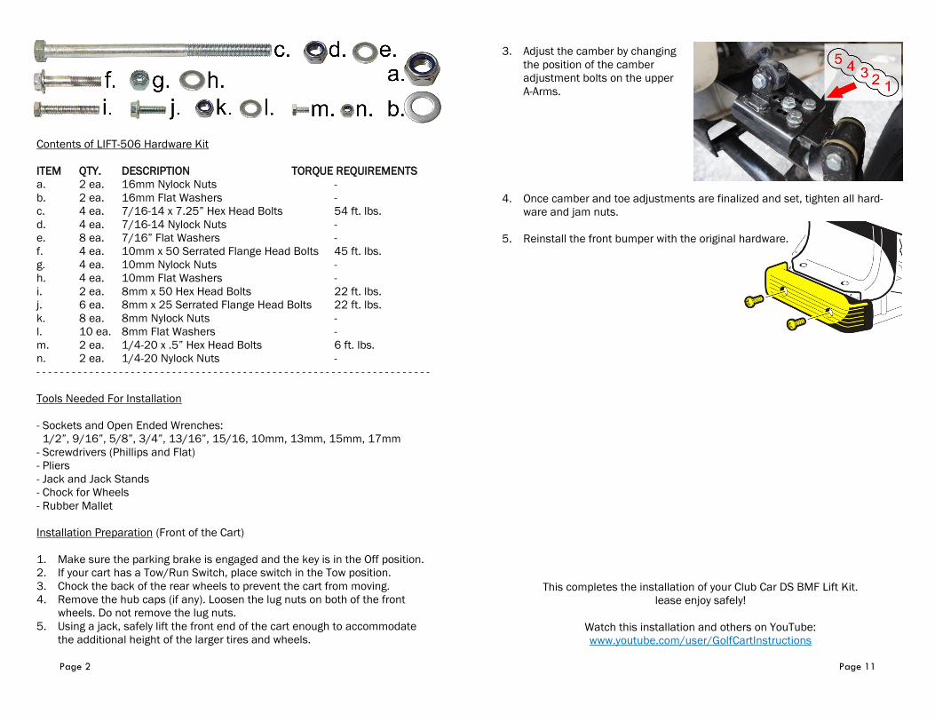
Contents of LIFT-506 Hardware Kit
ITEM QTY. DESCRIPTION TORQUE REQUIREMENTS
a. 2 ea. 16mm Nylock Nuts -
b. 2 ea. 16mm Flat Washers -
c. 4 ea. 7/16-14 x 7.25” Hex Head Bolts 54 ft. lbs.
d. 4 ea. 7/16-14 Nylock Nuts -
e. 8 ea. 7/16” Flat Washers -
f. 4 ea. 10mm x 50 Serrated Flange Head Bolts 45 ft. lbs.
g. 4 ea. 10mm Nylock Nuts -
h. 4 ea. 10mm Flat Washers -
i. 2 ea. 8mm x 50 Hex Head Bolts 22 ft. lbs.
j. 6 ea. 8mm x 25 Serrated Flange Head Bolts 22 ft. lbs.
k. 8 ea. 8mm Nylock Nuts -
l. 10 ea. 8mm Flat Washers -
m. 2 ea. 1/4-20 x .5” Hex Head Bolts 6 ft. lbs.
n. 2 ea. 1/4-20 Nylock Nuts -
- - - - - - - - - - - - - - - - - - - - - - - - - - - - - - - - - - - - - - - - - - - - - - - - - - - - - - - - - - - - - - - - - - -
Tools Needed For Installation
- Sockets and Open Ended Wrenches:
1/2”, 9/16”, 5/8”, 3/4”, 13/16”, 15/16, 10mm, 13mm, 15mm, 17mm
- Screwdrivers (Phillips and Flat)
- Pliers
- Jack and Jack Stands
- Chock for Wheels
- Rubber Mallet
Installation Preparation (Front of the Cart)
1. Make sure the parking brake is engaged and the key is in the Off position.
2. If your cart has a Tow/Run Switch, place switch in the Tow position.
3. Chock the back of the rear wheels to prevent the cart from moving.
4. Remove the hub caps (if any). Loosen the lug nuts on both of the front
wheels. Do not remove the lug nuts.
5. Using a jack, safely lift the front end of the cart enough to accommodate
the additional height of the larger tires and wheels.
Page 11
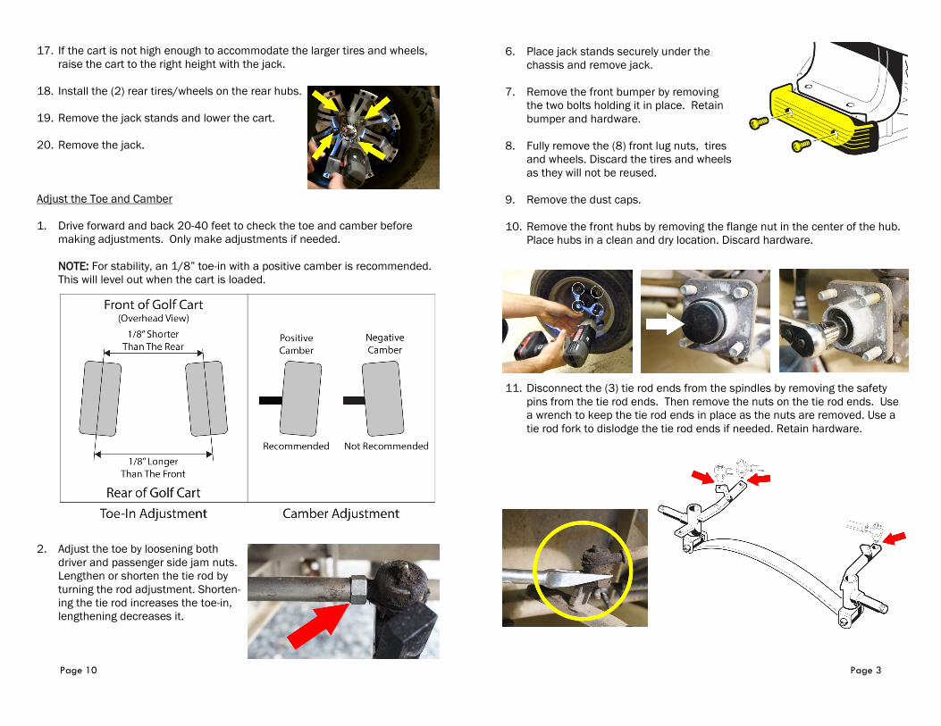
3. Adjust the camber by changing
the position of the camber
adjustment bolts on the upper
A-Arms.
4. Once camber and toe adjustments are finalized and set, tighten all hard-
ware and jam nuts.
5. Reinstall the front bumper with the original hardware.
This completes the installation of your Club Car DS BMF Lift Kit.
lease enjoy safely!
Watch this installation and others on YouTube:
www.youtube.com/user/GolfCartInstructions
Page 10
17. If the cart is not high enough to accommodate the larger tires and wheels,
raise the cart to the right height with the jack.
18. Install the (2) rear tires/wheels on the rear hubs.
19. Remove the jack stands and lower the cart.
20. Remove the jack.
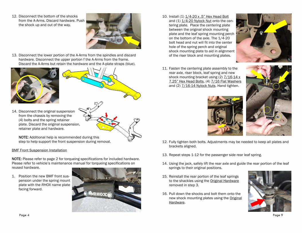
Adjust the Toe and Camber
1. Drive forward and back 20-40 feet to check the toe and camber before
making adjustments. Only make adjustments if needed.
NOTE: For stability, an 1/8” toe-in with a positive camber is recommended.
This will level out when the cart is loaded.
2. Adjust the toe by loosening both
driver and passenger side jam nuts.
Lengthen or shorten the tie rod by
turning the rod adjustment. Shorten-
ing the tie rod increases the toe-in,
lengthening decreases it.
Page 3
6. Place jack stands securely under the
chassis and remove jack.
7. Remove the front bumper by removing
the two bolts holding it in place. Retain
bumper and hardware.
8. Fully remove the (8) front lug nuts, tires
and wheels. Discard the tires and wheels
as they will not be reused.
9. Remove the dust caps.
10. Remove the front hubs by removing the flange nut in the center of the hub.
Place hubs in a clean and dry location. Discard hardware.
11. Disconnect the (3) tie rod ends from the spindles by removing the safety
pins from the tie rod ends. Then remove the nuts on the tie rod ends. Use
a wrench to keep the tie rod ends in place as the nuts are removed. Use a
tie rod fork to dislodge the tie rod ends if needed. Retain hardware.
Page 4
12. Disconnect the bottom of the shocks
from the A-Arms. Discard hardware. Push
the shock up and out of the way.
13. Disconnect the lower portion of the A-Arms from the spindles and discard
hardware. Disconnect the upper portion f the A-Arms from the frame.
Discard the A-Arms but retain the hardware and the A-plate straps (blue).
14. Disconnect the original suspension
from the chassis by removing the
(4) bolts and the spring retainer
plate. Discard the original suspension,
retainer plate and hardware.
NOTE: Additional help is recommended during this
step to help support the front suspension during removal.
BMF Front Suspension Installation
NOTE: Please refer to page 2 for torqueing specifications for included hardware.
Please refer to vehicle’s maintenance manual for torqueing specifications on
reused hardware.
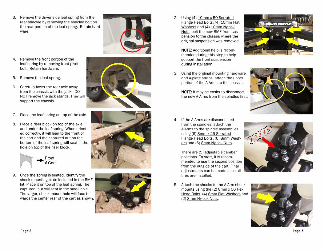
1. Position the new BMF front sus-
pension under the spring mount
plate with the RHOX name plate
facing forward.
Page 9
10. Install (1) 1/4-20 x .5” Hex Head Bolt
and (1) 1/4-20 Nylock Nut onto the cen-
tering plate. Place the centering plate
between the original shock mounting
plate and the leaf spring mounting perch
on the bottom of the axle. The 1/4-20
bolt head and nut will fit into the center
hole of the spring perch and original
shock mounting plate to aid in alignment
of the riser block and mounting plates.
11. Fasten the centering plate assembly to the
rear axle, riser block, leaf spring and new
shock mounting bracket using (2) 7/16-14 x
7.25” Hex Head Bolts, (4) 7/16 Flat Washers
and (2) 7/16-14 Nylock Nuts. Hand tighten.
12. Fully tighten both bolts. Adjustments may be needed to keep all plates and
brackets aligned.
13. Repeat steps 1-12 for the passenger side rear leaf spring.
14. Using the jack, safely lift the rear axle and guide the rear portion of the leaf
springs to their original positions.
15. Reinstall the rear portion of the leaf springs
to the shackles using the Original Hardware
removed in step 3.
16. Pull down the shocks and bolt them onto the
new shock mounting plates using the Original
Hardware.
Page 8
3. Remove the driver side leaf spring from the
rear shackle by removing the shackle bolt on
the rear portion of the leaf spring. Retain hard-
ware.
4. Remove the front portion of the
leaf spring by removing front pivot
bolt. Retain hardware.
5. Remove the leaf spring.
6. Carefully lower the rear axle away
from the chassis with the jack. DO
NOT remove the jack stands. They will
support the chassis.
7. Place the leaf spring on top of the axle.
8. Place a riser block on top of the axle
and under the leaf spring. When orient-
ed correctly, it will lean to the front of
the cart and the captured nut on the
bottom of the leaf spring will seat in the
hole on top of the riser block.
9. Once the spring is seated, identify the
shock mounting plate included in the BMF
kit. Place it on top of the leaf spring. The
captured nut will seat in the small hole.
The larger, shock mount hole will face to-
wards the center rear of the cart as shown.
Page 5
2. Using (4) 10mm x 50 Serrated
Flange Head Bolts, (4) 10mm Flat
Washers and (4) 10mm Nylock
Nuts, bolt the new BMF front sus-
pension to the chassis where the
original suspension was removed.
NOTE: Additional help is recom-
mended during this step to help
support the front suspension
during installation.
3. Using the original mounting hardware
and A-plate straps, attach the upper
portion of the A-Arms to the chassis.
NOTE: It may be easier to disconnect
the new A-Arms from the spindles first.
4. If the A-Arms are disconnected
from the spindles, attach the
A-Arms to the spindle assemblies
using (6) 8mm x 25 Serrated
Flange Head Bolts, (6) 8mm Wash-
ers and (6) 8mm Nylock Nuts.
There are (5) adjustable camber
positions. To start, it is recom-
mended to use the second position
from the outside of the cart. Final
adjustments can be made once all
tires are installed.
5. Attach the shocks to the A-Arm shock
mounts using the (2) 8mm x 50 Hex
Head Bolts, (4) 8mm Flat Washers and
(2) 8mm Nylock Nuts.

Page 6
6. Reinstall the (3) tie rod ends onto the
spindles using the original hardware.
If the safety pin hole is not entirely
visible through the castle nut’s gaps,
keep tightening.
Reinsert the safety pins
after the tie rod ends are
seated properly.
7. Reinstall the front
hubs removed on
page 3 using the (2)
16mm Nylock Nuts
and (2) 16mm Flat
Washers provided in
the hardware kit.
Reinstall the dust
caps.
8. Install the (2) front tires. The stock
tires and wheels will not work on the
newly lifted cart. Fully tighten the lug
nuts on both wheels.
NOTE: It is recommended to use at
least 22” tires on a 10” wheel with
an offset. The wheel shown is a
RHOX Vegas TIR-RX160 with a RHOX
Mojave tire, TIR-265.
9. Once the tire and wheels are fully secure, place the jack under the cart.
Remove any jack stands and lower the cart safely to the ground. Remove
the chocks behind the rear wheels.
NOTE: The front bumper will remain off until the camber and toe
adjustments are made at the end of the installation.
Installation Preparation (Rear of the Cart)
1. Make sure the parking brake is engaged and the key is in the Off position.
2. Chock the front of the front wheels to prevent the cart from moving.
Page 7
3. Remove the hub caps (if any) on the rear wheels. Loosen the lug nuts on
both rear wheels. Do not remove the lug nuts.
4. Place a jack securely under the rear axle. Safely lift the rear end of the cart
enough to accommodate the additional height of the larger tires and
wheels.
5. Place jack stands under the chassis on
both sides of the cart to stabilize it. DO
NOT remove the jack.
6. Fully remove the (8) rear lug nuts,
tires and wheels. Discard the tires and
wheels as they will not be reused.
BMF Rear Suspension Installation
Safety Note: The rear axle is only held up by the (2) leaf springs and the jack.
For safety reasons, complete one side of the suspension at a time. The photos
below show the Driver side.
1. Unbolt the bottom portion of the driver side
shock from the shock mounting plate. Push
the shock upward and out of the way. Retain
hardware.
2. With the axle supported by the
jack, remove the (2) nuts
holding the driver’s side U-bolt
around the rear axle, leaf spring
and shock mounting plate.
Remove and discard hardware.
NOTE: The shock mounting
plate will remain attached to the
brake cable.