Embed Size (px)
Citation preview

Light FieldsPROPERTIES AND APPLICATIONS

OutlineWhat are light fields
Acquisition of light fields from a 3D scene from a real world scene
Image rendering from light fields Changing viewing angle Changing the focal plane
Sampling and reconstruction Depth vs spectral support Optimal reconstruction Analysis of light transport

OutlineWhat are light fields
Acquisition of light fields from a 3D scene from a real world scene
Image rendering from light fields Changing viewing angle Changing the focal plane
Sampling and reconstruction Depth vs spectral support Optimal reconstruction Analysis of light transport
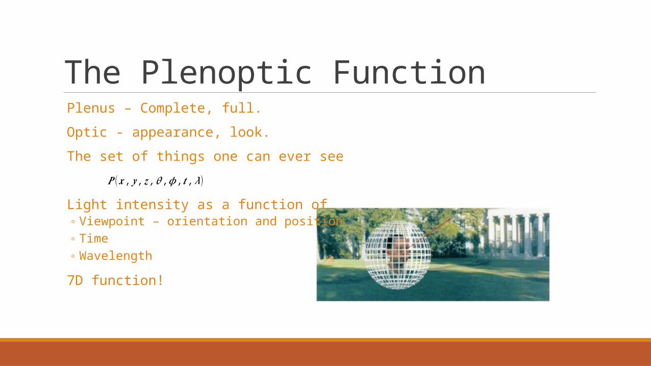
The Plenoptic Function Plenus – Complete, full.
Optic - appearance, look.
The set of things one can ever see
Light intensity as a function of◦ Viewpoint – orientation and position◦ Time◦ Wavelength
7D function!
𝑷 (𝒙 , 𝒚 , 𝒛 ,𝜽 ,𝝓 ,𝒕 ,𝝀)
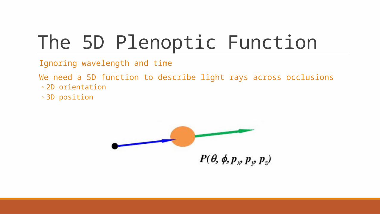
The 5D Plenoptic Function Ignoring wavelength and time
We need a 5D function to describe light rays across occlusions◦ 2D orientation◦ 3D position
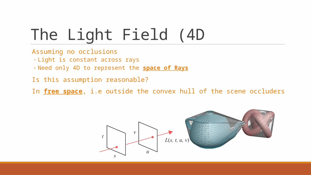
The Light Field (4D Assuming no occlusions
◦ Light is constant across rays◦ Need only 4D to represent the space of Rays
Is this assumption reasonable?
In free space, i.e outside the convex hull of the scene occluders

The Light Field Parameterizations
◦ Point on a Plane or curved Surface (2D) and Direction on a Hemisphere (2D)◦ Two Points on a Sphere◦ Two Points on two different Planes

Two Plane Parameterization Convenient parameterization for computational photography
Why?• Similar to camera geometry (i.e. film plane vs lens plane)• Linear parameterization - easy computations , no trigonometric functions, etc.

2D light fieldUsed for visualization. Assume the world is flat (2D)
𝐿(𝑠 , 𝑡 ,: ,:)
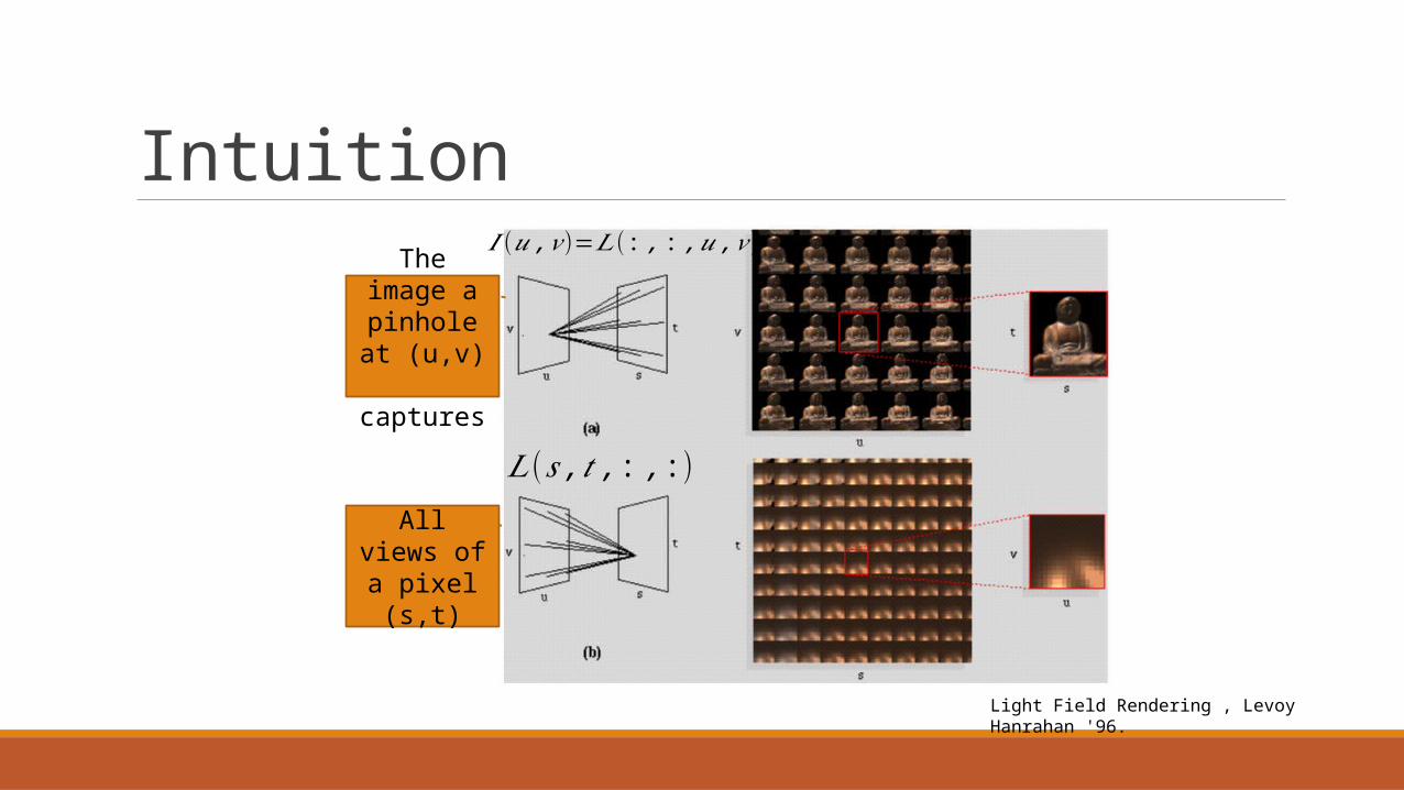
𝐼 (𝑢 ,𝑣)=𝐿(: , : ,𝑢 ,𝑣)
The image a pinhole at
(u,v) captures
All views of a pixel (s,t)
Intuition
Light Field Rendering , Levoy Hanrahan '96.
OutlineWhat are light fields
Acquisition of light fields from a 3D scene from a real world scene
Image rendering from light fields Changing viewing angle Changing the focal plane
Sampling and reconstruction Depth vs spectral support Optimal reconstruction Analysis of light transport
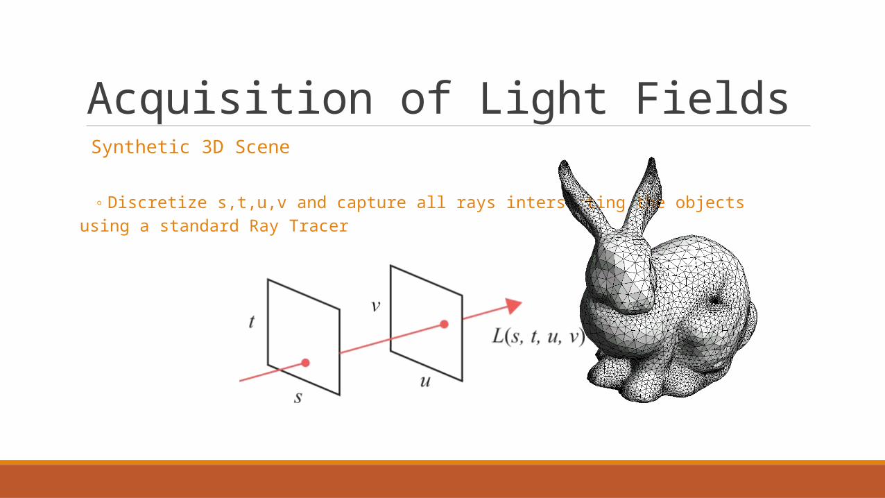
Acquisition of Light Fields Synthetic 3D Scene
◦ Discretize s,t,u,v and capture all rays intersecting the objects using a standard Ray Tracer

Acquisition of Light FieldsReal world scenes
Will be explained in more detail next week…

OutlineWhat are light fields
Acquisition of light fields from a 3D scene from a real world scene
Image rendering from light fields Changing viewing angle Changing the focal plane
Sampling and reconstruction Depth vs spectral support Optimal reconstruction Analysis of light transport

Changing the View Point Problem: Computer Graphics
◦ Render a novel view point without expensive ray tracing
Solution:◦ Sample a Synthetic light field using Ray Tracing◦ Use the Light Field to generate any point of view, no need to Ray Trace
Light Field Rendering , Levoy Hanrahan '96.
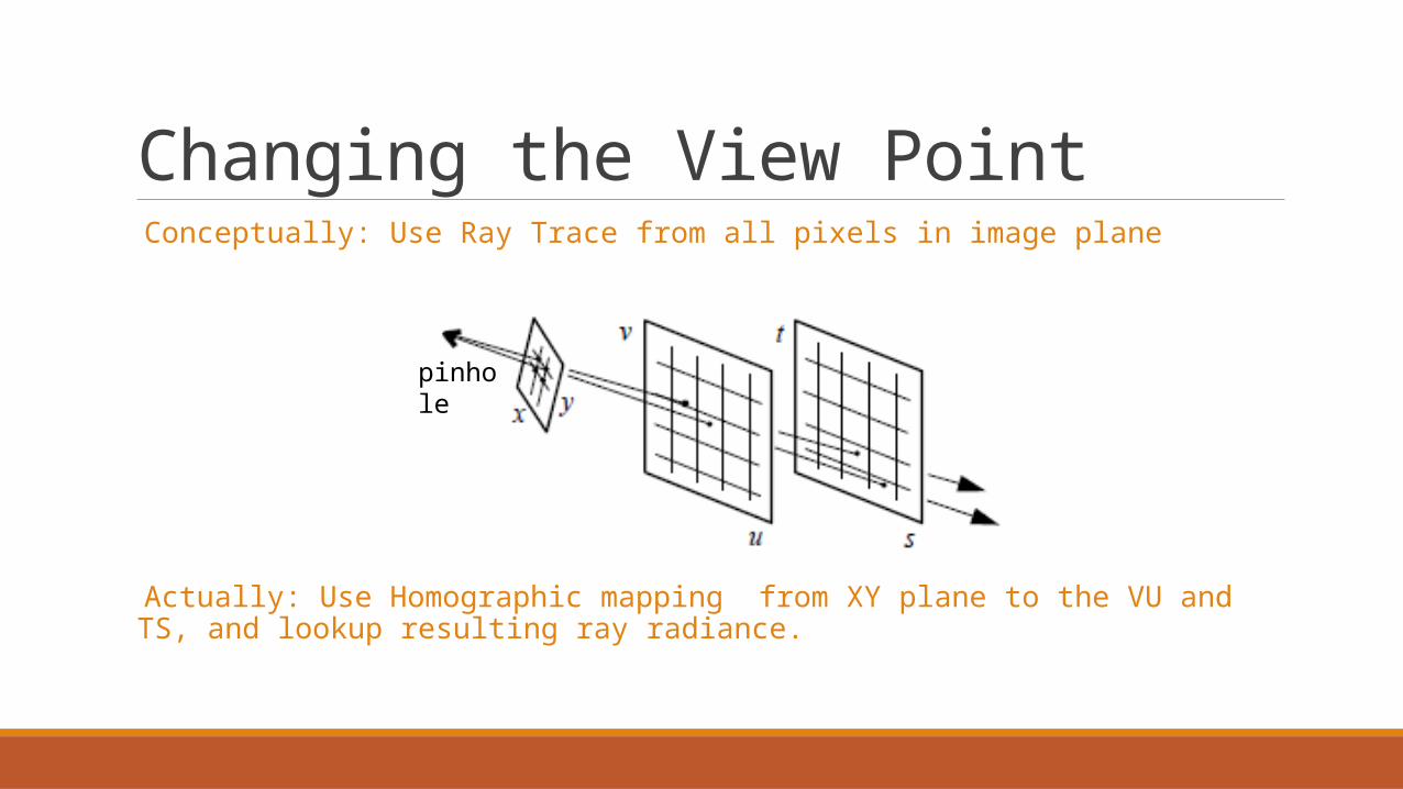
Changing the View Point Conceptually: Use Ray Trace from all pixels in image plane
Actually: Use Homographic mapping from XY plane to the VU and TS, and lookup resulting ray radiance.
pinhole
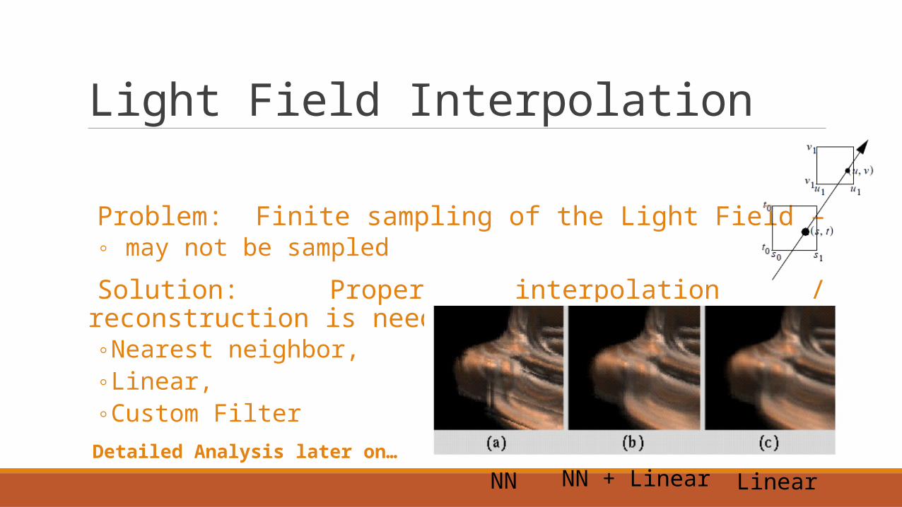
Light Field Interpolation
Problem: Finite sampling of the Light Field – ◦ may not be sampled
Solution: Proper interpolation / reconstruction is needed◦ Nearest neighbor,◦ Linear,◦ Custom Filter
Detailed Analysis later on…
NN NN + Linear Linear

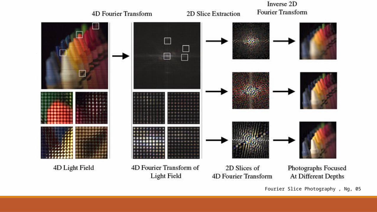
Changing the focal plane
Fourier Slice Photography , Ng, 05

In-Camera Light Field Parameterization

The camera operator Can define a camera as an operator on the Light Field.
◦ The conventional camera operator:
y
x [Stroebel et al. 1986]
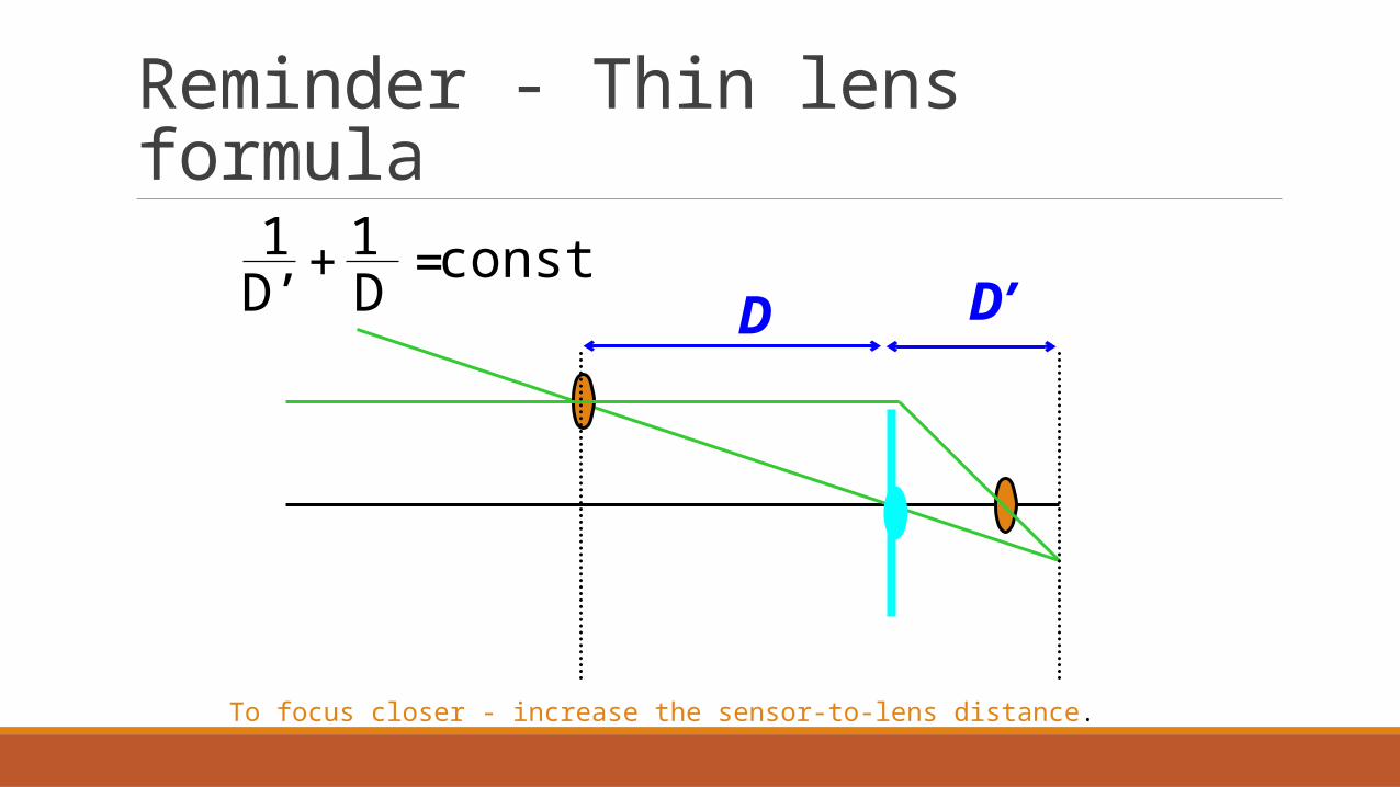
Reminder - Thin lens formula
D D’1D’ D
1 const+ =
To focus closer - increase the sensor-to-lens distance.

Refocusing - Reparameterization
𝐿𝐹 ′ (𝑢 , 𝑥 )=𝐿𝐹 (𝑢 ,𝑢+𝑥−𝑢𝛼
)
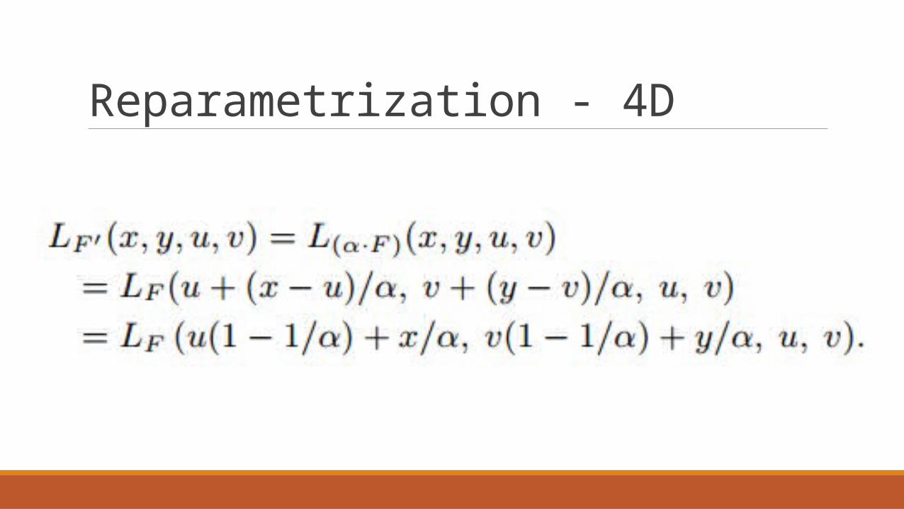
Reparametrization - 4D

Refocusing - Reparameterization
RefocusChange of distance
between planes
Reparameterization of the light field
Shearing of the Light field

Refocusing camera operator Shear and Integrate the original light field
*(cos term from conventional camera model is absorbed into L)
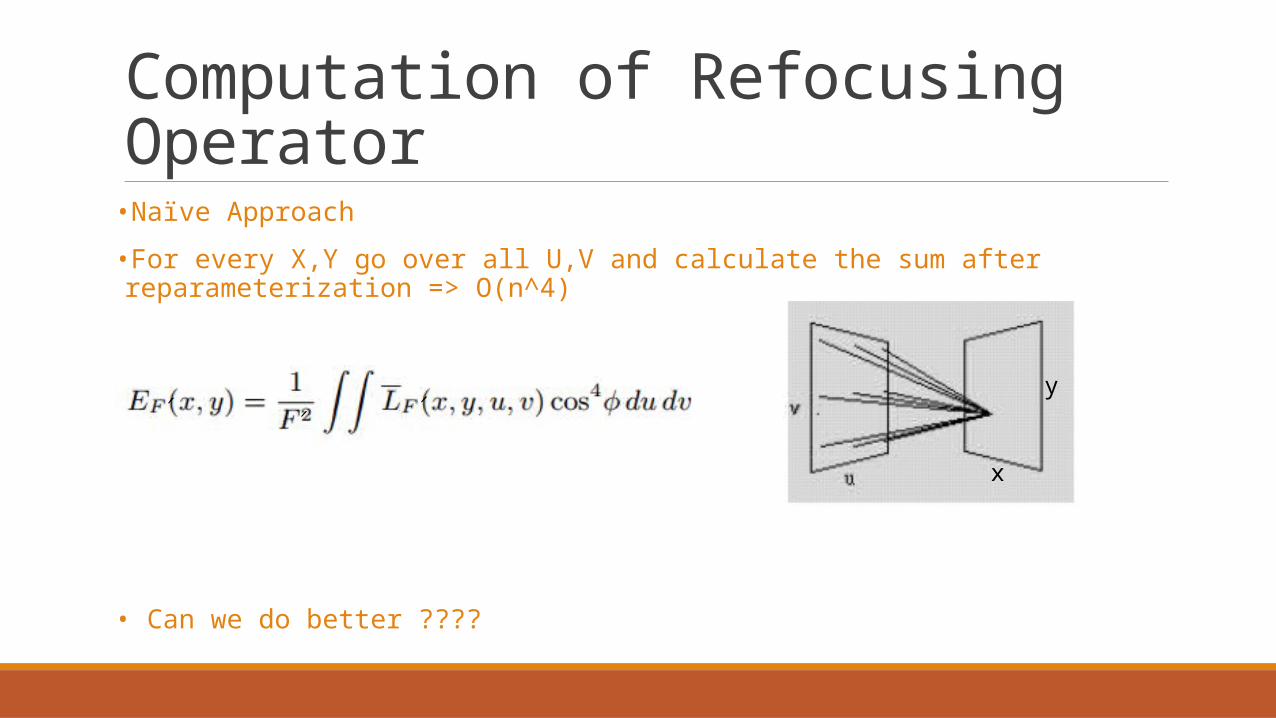
Computation of Refocusing Operator
•Naïve Approach
•For every X,Y go over all U,V and calculate the sum after reparameterization => O(n^4)
• Can we do better ????
y
x
′ ′′

Fourier Slice Theorem
• F – Fourier Transform Operator
• I – Integral Projection Operator
• S – Slicing Operator
𝐹 ∘ 𝐼=𝑆∘ 𝐹
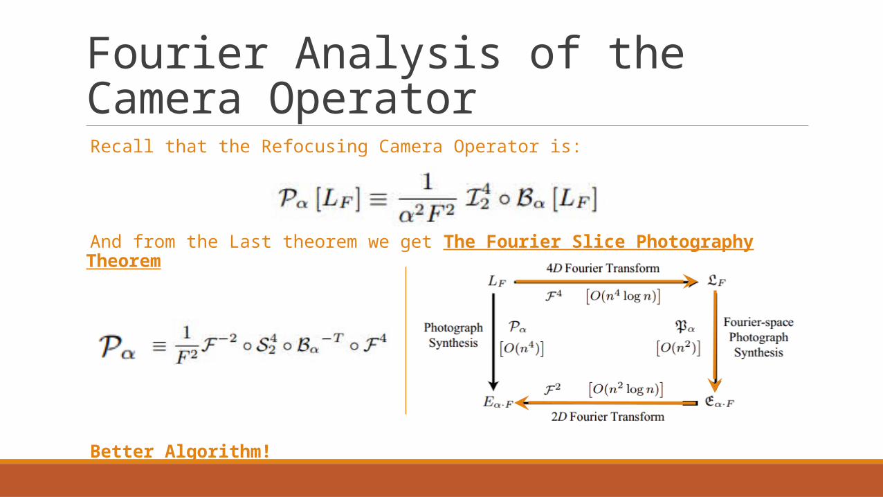
Fourier Analysis of the Camera Operator
Recall that the Refocusing Camera Operator is:
And from the Last theorem we get The Fourier Slice Photography Theorem
Better Algorithm!
Fourier Slice Photography , Ng, 05

Fourier Slice Photography Thm – More corollaries
Two important results that are worth mentioning:
1. Filtered Light Field Photography Thm
2. The light field dimensionality gap
*K=?

Filtered Light Field Photography Thm
Theorem: Filtered Light Field Photography
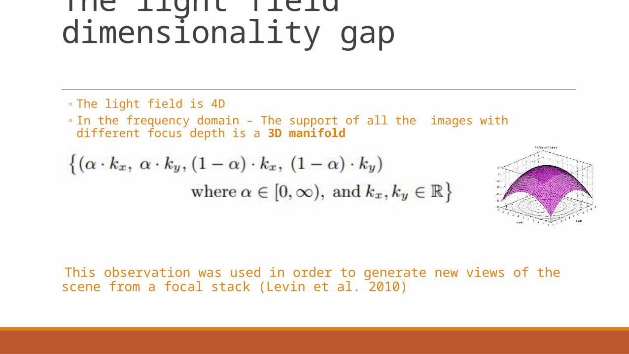
The light field dimensionality gap
◦ The light field is 4D◦ In the frequency domain – The support of all the images with different focus depth is a 3D manifold
This observation was used in order to generate new views of the scene from a focal stack (Levin et al. 2010)

OutlineWhat are light fields
Acquisition of light fields from a 3D scene from a real world scene
Image rendering from light fields Changing viewing angle Changing the focal plane
Sampling and reconstruction Depth vs spectral support Optimal reconstruction Analysis of light transport

Light Field Sampling•Light Field Acquisition – Discretization
•Light Field Sampling is LimitedExample – Camera Array:
u,v
t,s
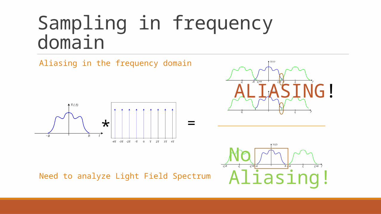
Sampling in frequency domain Aliasing in the frequency domain
Need to analyze Light Field Spectrum
* =
ALIASING!
No Aliasing!
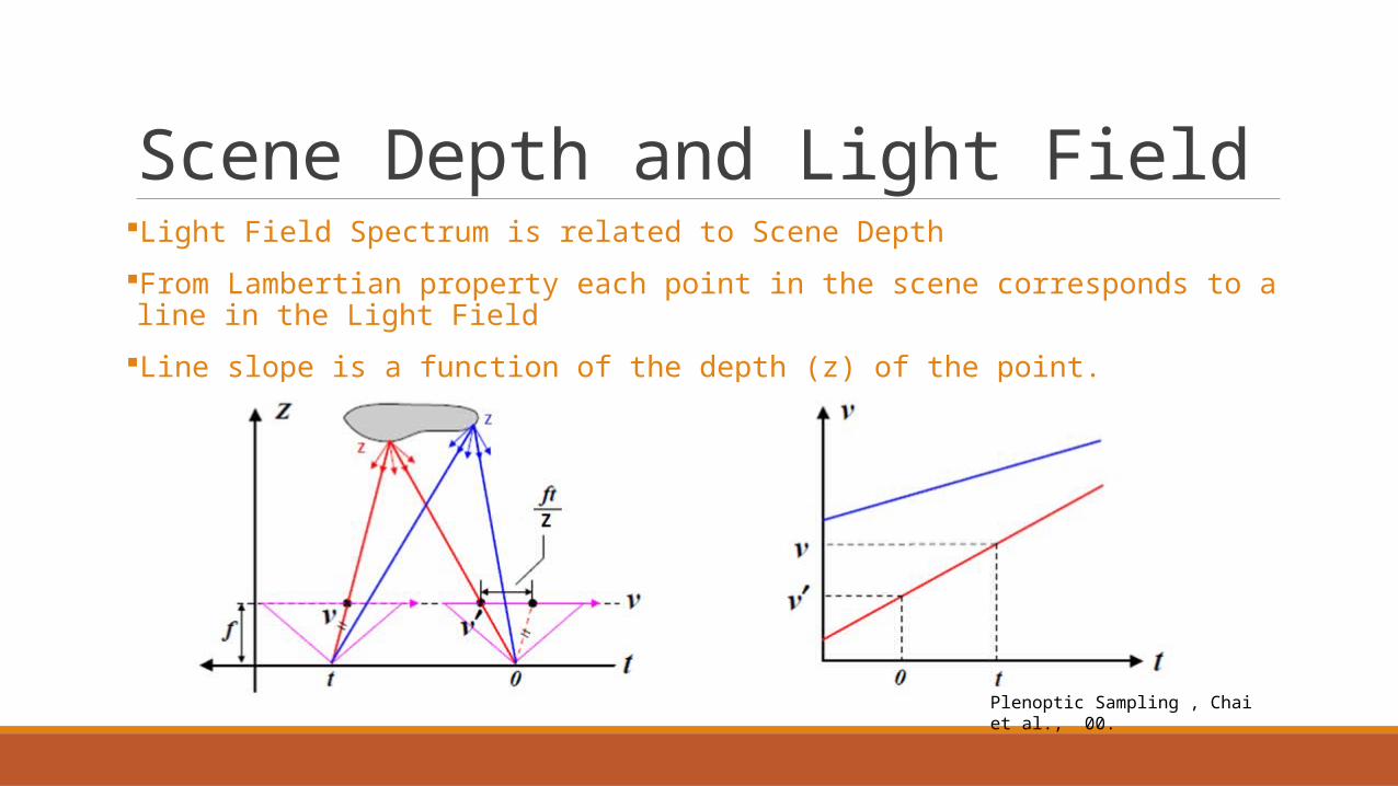
Scene Depth and Light FieldLight Field Spectrum is related to Scene Depth
From Lambertian property each point in the scene corresponds to a line in the Light Field
Line slope is a function of the depth (z) of the point.
Plenoptic Sampling , Chai et al., 00.
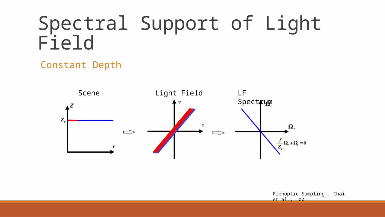
Spectral Support of Light Field Constant Depth
Scene Light Field LF Spectrum
Plenoptic Sampling , Chai et al., 00.
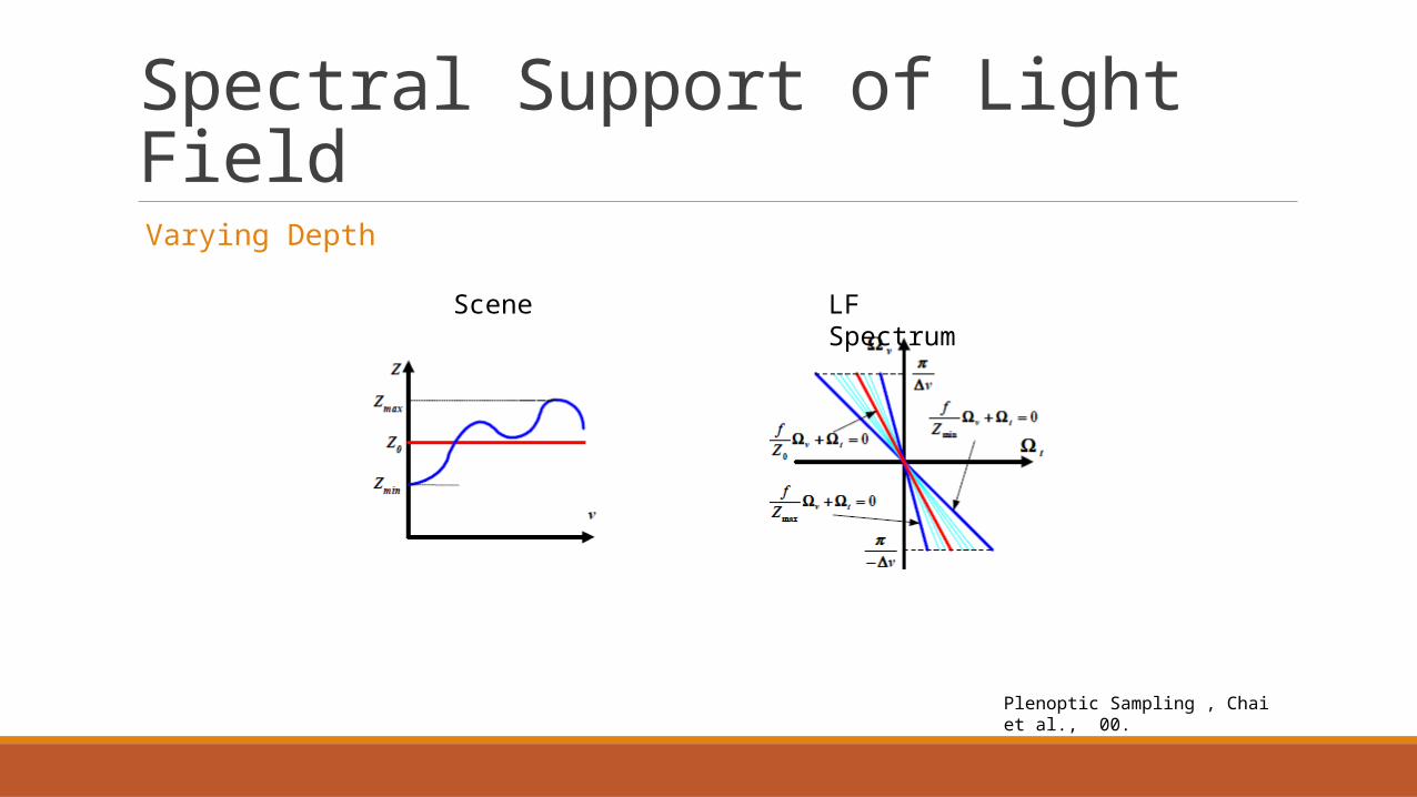
Spectral Support of Light Field Varying Depth
Scene LF Spectrum
Plenoptic Sampling , Chai et al., 00.
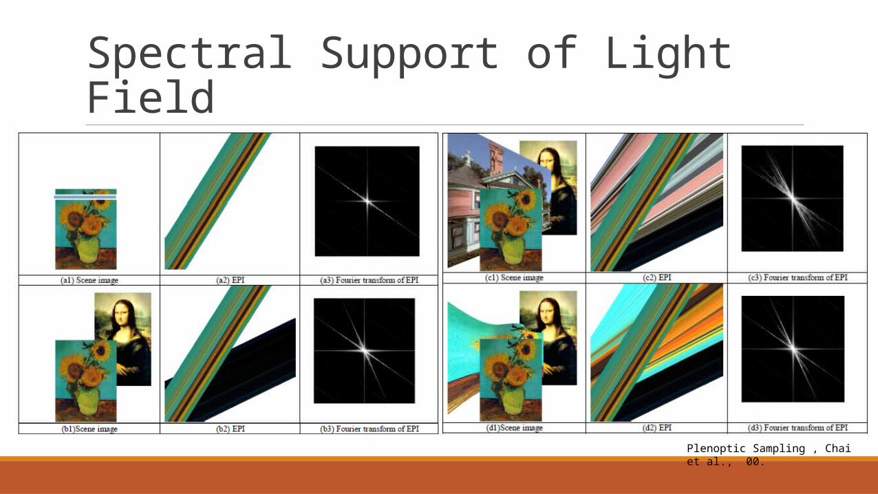
Spectral Support of Light Field
Plenoptic Sampling , Chai et al., 00.

Reconstruction Filters
Optimal Slope for filter:
Plenoptic Sampling , Chai et al., 00.

Limitations Assumptions
◦ Lambertian surfaces
◦ Free Space – No occlusions

Frequency Analysis of Light Transport
•Informally: Different features of lighting and scene causes different effects in the Frequency Content
•Blurry Reflections
•Shadow Boundries Low frequencyHigh frequency
A Frequency analysis of Light Transport , Durand et al. 05.
Not Wave Optics!!!
Frequency Analysis of Light Transport
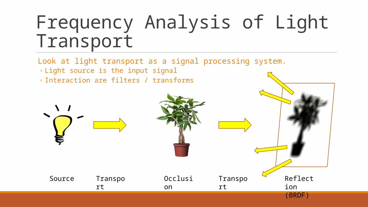
Look at light transport as a signal processing system.◦ Light source is the input signal◦ Interaction are filters / transforms
Source Transport Occlusion Transport Reflection(BRDF)
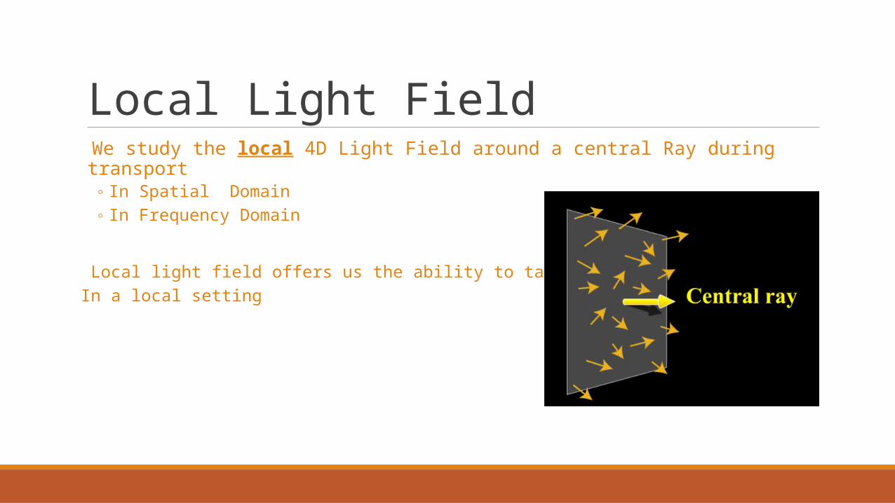
Local Light Field We study the local 4D Light Field around a central Ray during transport
◦ In Spatial Domain◦ In Frequency Domain
* Local light field offers us the ability to talk about the Spectrum In a local setting
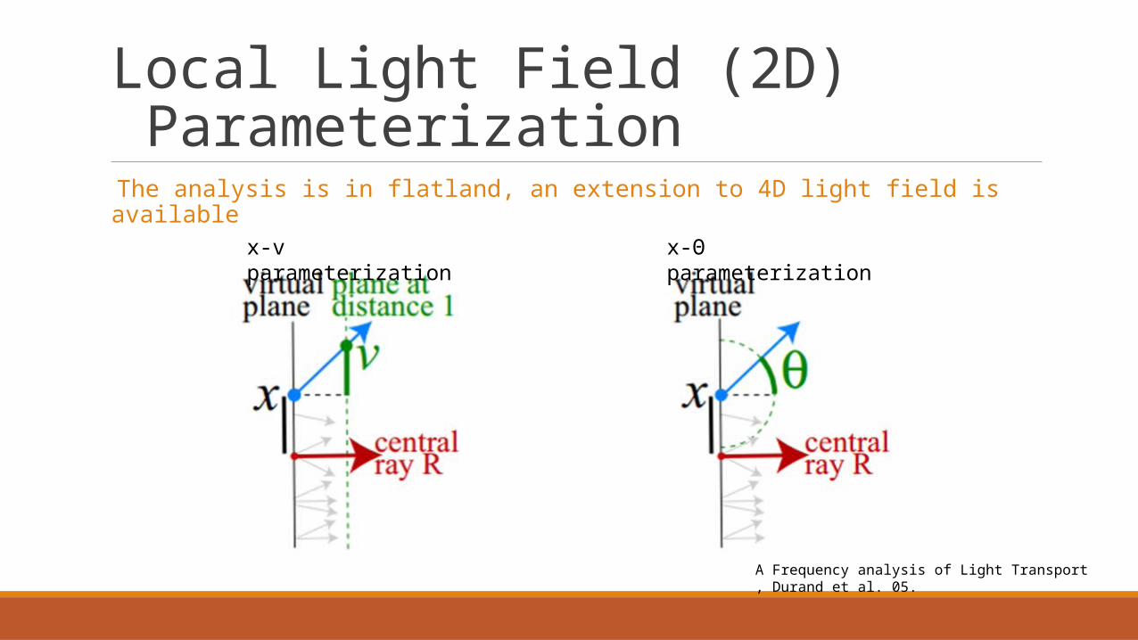
Local Light Field (2D) Parameterization
The analysis is in flatland, an extension to 4D light field is available
x-v parameterization x-Θ parameterization
A Frequency analysis of Light Transport , Durand et al. 05.

Example Scenario
Reflection
A Frequency analysis of Light Transport , Durand et al. 05.

Light Transport – Spatial Domain Light Propagation Shear of the local Light Field
◦ No change in slope (v)◦ Linear change in displacement (X)
+¿
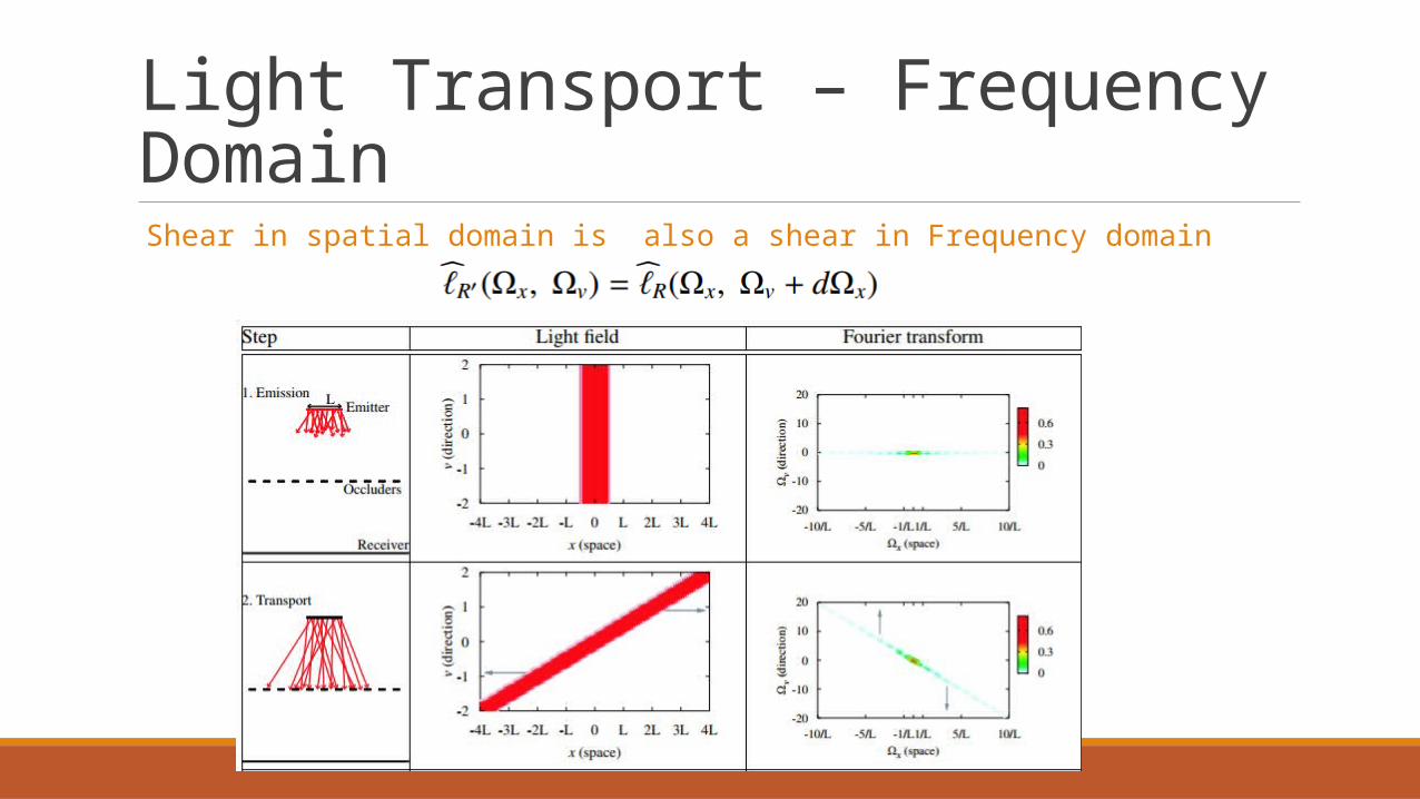
Light Transport – Frequency Domain
Shear in spatial domain is also a shear in Frequency domain
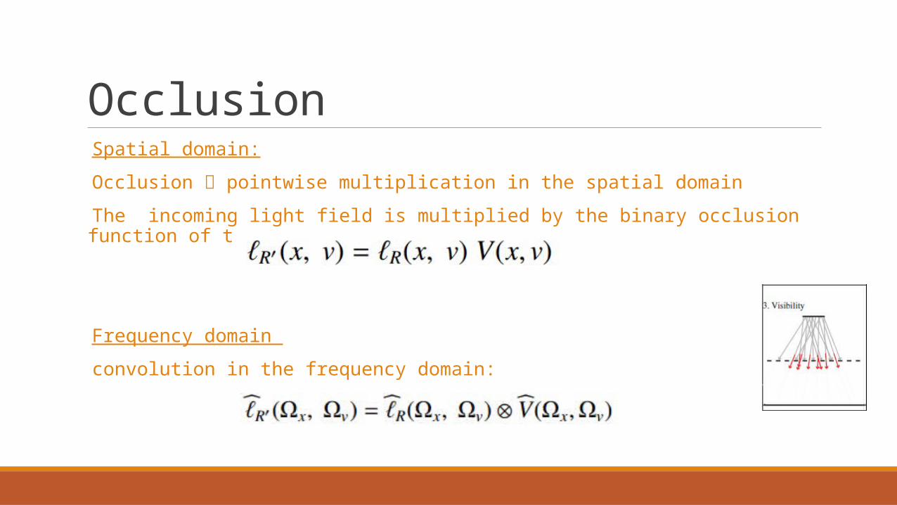
Occlusion Spatial domain:
Occlusion pointwise multiplication in the spatial domain
The incoming light field is multiplied by the binary occlusion function of the occluders.
Frequency domain
convolution in the frequency domain:

Occlusion – example
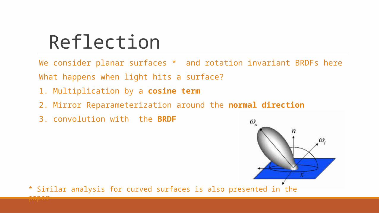
Reflection We consider planar surfaces * and rotation invariant BRDFs here
What happens when light hits a surface?
1. Multiplication by a cosine term
2. Mirror Reparameterization around the normal direction
3. convolution with the BRDF
* Similar analysis for curved surfaces is also presented in the paper
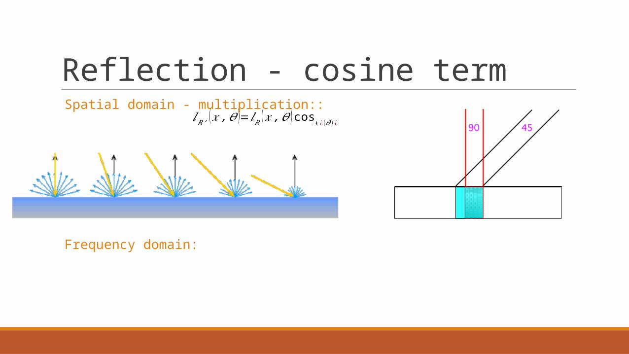
Reflection - cosine term Spatial domain - multiplication::
Frequency domain:
𝑙𝑅 ′ (𝑥 ,𝜃 )=𝑙𝑅 (𝑥 , 𝜃 ) cos+¿(𝜃 )¿

cosine term example
Incoming Light field
Light fieldAfter cosine
term

Reflection – Mirror reparameterization
Mirror Reparameterization around the normal direction ◦ Using the law of reflection
Frequency domain: mirror in the spatial domain => mirror in the frequency domain ◦ =
𝜃𝑖𝑛𝜃𝑜𝑢𝑡
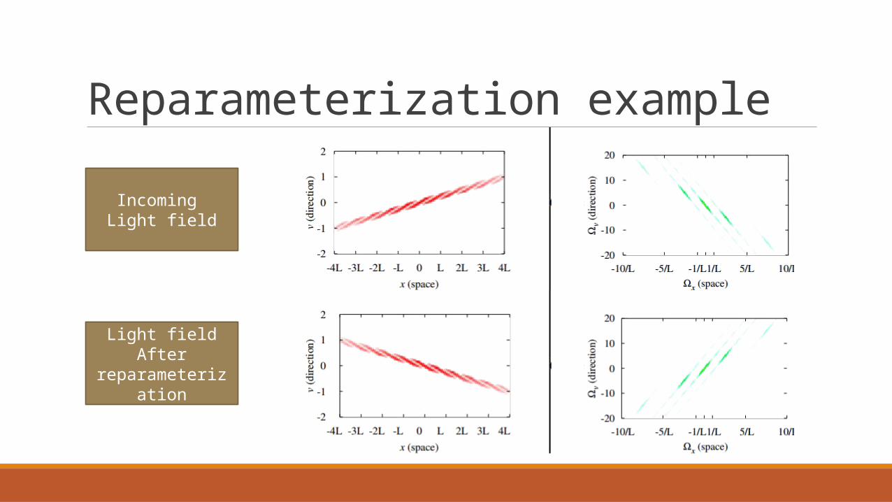
Reparameterization example
Incoming Light field
Light fieldAfter
reparameterization
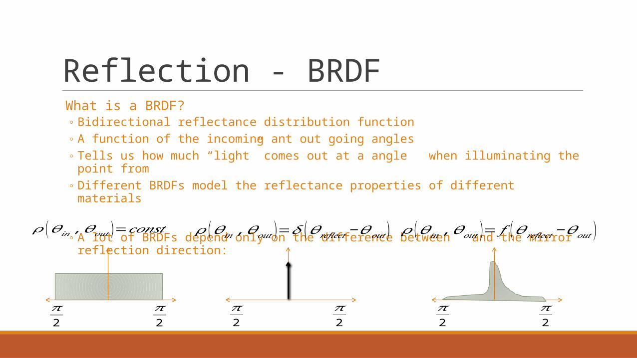
Reflection - BRDF What is a BRDF?
◦ Bidirectional reflectance distribution function◦ A function of the incoming ant out going angles ◦ Tells us how much “light” comes out at a angle when illuminating the point from ◦ Different BRDFs model the reflectance properties of different materials
◦ A lot of BRDFs depend only on the difference between and the mirror reflection direction:
𝜋2
𝜋2
𝜋2
𝜋2
𝜌 (𝜃𝑖𝑛 , 𝜃𝑜𝑢𝑡 )=𝑐𝑜𝑛𝑠𝑡 𝜌 (𝜃𝑖𝑛 , 𝜃𝑜𝑢𝑡 )=𝛿 (𝜃 𝑟𝑒𝑓𝑙𝑒𝑐𝑡−𝜃𝑜𝑢𝑡 )
𝜋2
𝜋2
𝜌 (𝜃𝑖𝑛 , 𝜃𝑜𝑢𝑡 )= 𝑓 (𝜃𝑟𝑒𝑓𝑙𝑒𝑐𝑡 −𝜃𝑜𝑢𝑡 )

BRDF Intuition
𝜃
𝜋2
𝜋2
𝜃−𝜃
−𝑎 𝑎
𝜋2
𝜋2
𝜃 𝜃−𝜃* =
Assume a box BRDF, flat surface and a light source at infinity with angle .
Assume a Specular BRDF, flat surface and a light source at infinity with angle .
directiondirection
x (space)
x (space)
Reflection - BRDFSpatial domain:
The BRDF action on a light field is a convolution with the BRDF function
Frequency domain:
Convolution is changed into pointwise multiplication
=
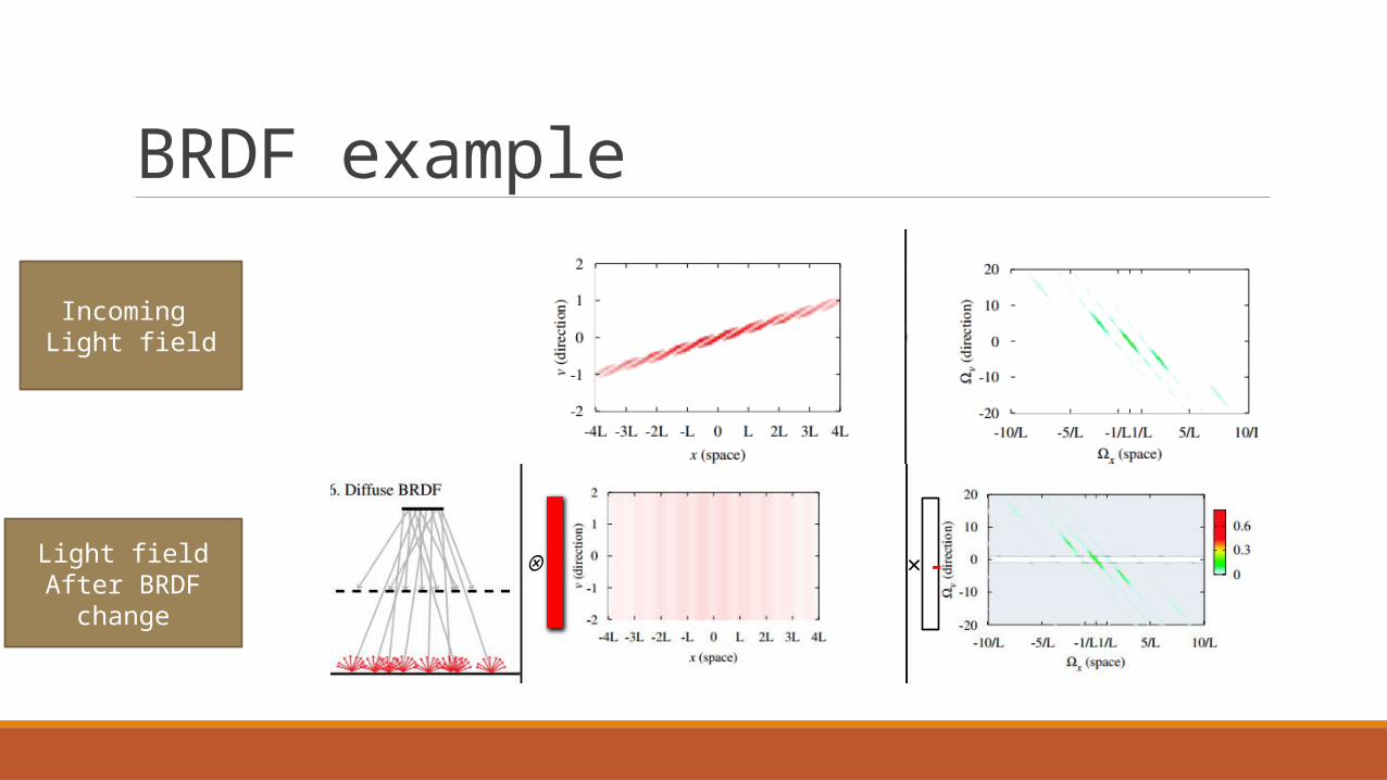
BRDF example
Incoming Light field
Light fieldAfter BRDF change
-×⊗