Embed Size (px)
Citation preview
SEN
SOR
S
More information online at bannerengineering.com300
LIGHT GAUGING ULTRASONIC MEASURING ARRAYS RADAR
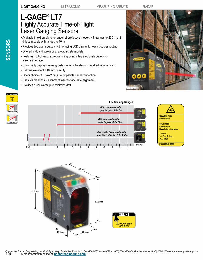
L-GAGE® LT7Highly Accurate Time-of-Flight Laser Gauging Sensors• Available in extremely long-range retroreflective models with ranges to 250 m or in
diffuse models with ranges to 10 m
• Provides two alarm outputs with ongoing LCD display for easy troubleshooting
• Offered in dual-discrete or analog/discrete models
• Features TEACH-mode programming using integrated push buttons or a serial interface
• Continually displays sensing distance in millimeters or hundredths of an inch
• Delivers excellent ±10 mm linearity
• Offers choice of RS-422 or SSI-compatible serial connection
• Uses visible Class 2 alignment laser for accurate alignment
• Provides quick warmup to minimize drift
LT7 Sensing Ranges
Diffuse models with gray targets: 0.5 - 7 m
Diffuse models with white targets: 0.5 - 10 m
Retroreflective models with specified reflector: 0.5 - 250 m
Meters250 . . . 10 9 8 7 6 5 4 3 2 1
ACCESSORIES
page302
ONLINE
AUTOCAD, STEP, IGES & PDF
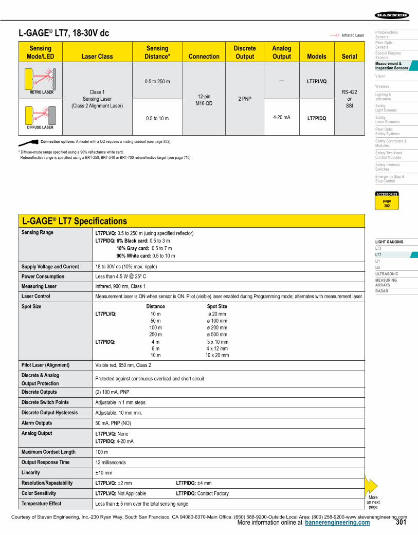
95.0 mm
93.0 mm
42.0 mm
81.5 mm
42.0 mm
RETRO LASER
LASER DIFFUSE
Operating ModeLaser Class 1
Setup ModeLaser Class 2Do not stare into beam
Courtesy of Steven Engineering, Inc.-230 Ryan Way, South San Francisco, CA 94080-6370-Main Office: (650) 588-9200-Outside Local Area: (800) 258-9200-www.stevenengineering.com
LIGHT GAUGING
LT3
LT7
LH
LG
ULTRASONIC
MEASURINGARRAYS
RADAR
More information online at bannerengineering.com 301
PhotoelectricsSensors
Fiber OpticSensors
Special PurposeSensors
Measurement & Inspection Sensors
Vision
Wireless
Lighting &Indicators
Safety Light Screens
Safety Laser Scanners
Fiber OpticSafety Systems
Safety Controllers & Modules
Safety Two-Hand Control Modules
Safety Interlock Switches
Emergency Stop & Stop Control
L-GAGE® LT7, 18-30V dc
SensingMode/LED Laser Class
SensingDistance* Connection
DiscreteOutput
AnalogOutput Models Serial
RETRO LASER Class 1Sensing Laser
(Class 2 Alignment Laser)
0.5 to 250 m
12-pin M16 QD
2 PNP
— LT7PLVQ
RS-422or
SSI
DIFFUSE LASER
0.5 to 10 m 4-20 mA LT7PIDQ
L-GAGE® LT7 SpecificationsSensing Range LT7PLVQ: 0.5 to 250 m (using specified reflector)
LT7PIDQ: 6% Black card: 0.5 to 3 m 18% Gray card: 0.5 to 7 m 90% White card: 0.5 to 10 m
Supply Voltage and Current 18 to 30V dc (10% max. ripple)
Power Consumption Less than 4.5 W @ 25º C
Measuring Laser Infrared, 900 nm, Class 1
Laser Control Measurement laser is ON when sensor is ON. Pilot (visible) laser enabled during Programming mode; alternates with measurement laser.
Spot Size Distance Spot SizeLT7PLVQ: 10 m ø 20 mm 50 m ø 100 mm 100 m ø 200 mm 250 m ø 500 mmLT7PIDQ: 4 m 3 x 10 mm 6 m 4 x 12 mm 10 m 10 x 20 mm
Pilot Laser (Alignment) Visible red, 650 nm, Class 2
Discrete & Analog
Output Protection Protected against continuous overload and short circuit
Discrete Outputs (2) 100 mA, PNP
Discrete Switch Points Adjustable in 1 mm steps
Discrete Output Hysteresis Adjustable, 10 mm min.
Alarm Outputs 50 mA, PNP (NO)
Analog Output LT7PLVQ: NoneLT7PIDQ: 4-20 mA
Maximum Cordset Length 100 m
Output Response Time 12 milliseconds
Linearity ±10 mm
Resolution/Repeatability LT7PLVQ: ±2 mm LT7PIDQ: ±4 mm
Color Sensitivity LT7PLVQ: Not Applicable LT7PIDQ: Contact Factory
Temperature Effect Less than ± 5 mm over the total sensing rangeMore
on next page
Connection options: A model with a QD requires a mating cordset (see page 302).
* Diffuse-mode range specified using a 90% reflectance white card. Retroreflective range is specified using a BRT-250, BRT-540 or BRT-700 retroreflective target (see page 710).
Infrared Laser
ACCESSORIES
page302
Courtesy of Steven Engineering, Inc.-230 Ryan Way, South San Francisco, CA 94080-6370-Main Office: (650) 588-9200-Outside Local Area: (800) 258-9200-www.stevenengineering.com
SEN
SOR
S
More information online at bannerengineering.com302
LIGHT GAUGING ULTRASONIC MEASURING ARRAYS RADAR
Class 2 (Visible Alignment Laser)Lasers that emit visible radiation in the wavelength range from 400 to 700 nm where eye protection is normally afforded by aversion responses, including the blink reflex. This reaction may be expected to provide adequate protection under reasonably foreseeable conditions of operation, including the use of optical instruments for intrabeam viewing. Reference 60825-1 Amend. 2 © IEC:2001(E), section 8.2.
Class 1 (Infrared Sensing Laser)Lasers that are safe under reasonably foreseeable conditions of operation, including the use of optical instruments for intrabeam viewing. Reference 60825-1 Amend. 2 © IEC:2001(E), section 8.2.
Operating ModeLaser Class 1
Setup ModeLaser Class 2Do not stare into beam
L-GAGE® LT7 SpecificationsMinimum Analog
Window Size
LT7PLVQ: Not ApplicableLT7PIDQ: 300 mm
Adjustments Push-button-directed password enable/disable, measurement unit select, offset value select, output limits set, output mode select, analog output slope select (diffuse models only) and output limit manual adjust. See data sheet for information.
Serial Interface RS-422 or SSI compatible
Serial Measurement Speed SSI: 1.4 milliseconds (SSI cycle 80 microseconds) RS-422: 2.9 milliseconds @ 57.6 kBaud
Indicators 4 LEDs: Green: Power ON/OFF Red: Alarm (Error) LED Orange: Output 1 and Output 2 conducting LEDs
2-line digital LCD display. See data sheet for detailed information.
Construction ABS shock-resistant housing; PMMA window; polycarbonate displays
Weight Approximately 230 g
Environmental Rating IEC IP67
Connections 12-pin M16 connector; 100 m max. cable length; use only cables listed on page 302.
Operating Conditions Temperature: -10° to +50° C in continuous operation
Storage Temperature -30° to +75° C
Vibration/Shock EN 60947-5-2
Application Notes • All specifications are based on the specified surface at constant ambient conditions and following a minimum operating time of 15 minutes.• For best accuracy, allow a 15-minute warmup before programming or operating• Crosstalk avoidance: Light spots must be separated by at least 200 mm.
Certifications
Hookup Diagrams MI05 (p. 759)
(cont’d)
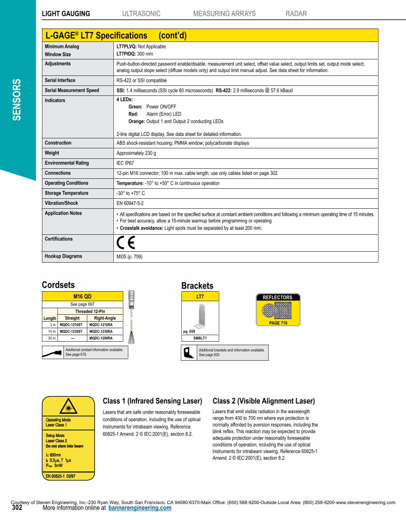
BracketsLT7
SMBLT7
pg. 658
M16 QDSee page 697
Length
Threaded 12-Pin
Straight Right-Angle3 m MQDC-1210ST MQDC-1210RA
10 m MQDC-1230ST MQDC-1230RA
30 m — MQDC-1290RA
Cordsets REFLECTORS
PAGE 710
REFLECTORS
Additional cordset information available.See page 679.
Additional brackets and information available.See page 620.
Courtesy of Steven Engineering, Inc.-230 Ryan Way, South San Francisco, CA 94080-6370-Main Office: (650) 588-9200-Outside Local Area: (800) 258-9200-www.stevenengineering.com
759759
Accessories
Reference
Hookups
Wiring Diagrams
Glossary
International Reps
More information online at bannerengineering.com
Measurement and Inspection Hookups
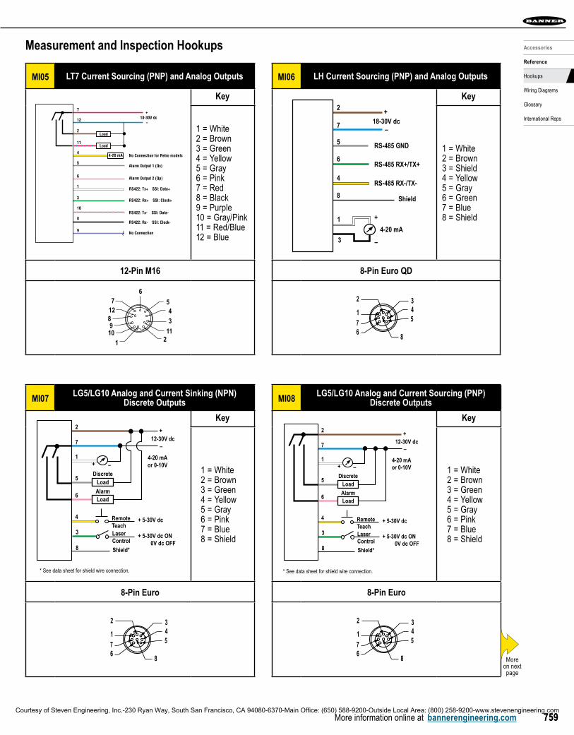
MI05 LT7 Current Sourcing (PNP) and Analog Outputs
7
12
2
4
11
5
3
1
6
9
8
10
18-30V dc
No Connection for Retro models
Alarm Output 1 (Qs)
Alarm Output 2 (Qp)
RS422: Tx+ SSI: Data+
RS422: Rx+ SSI: Clock+
RS422: Rx- SSI: Clock-
No Connection
RS422: Tx- SSI: Data-
–
+
4-20 mA
Load
Load
Key
1 = White2 = Brown3 = Green4 = Yellow5 = Gray6 = Pink7 = Red8 = Black9 = Purple10 = Gray/Pink11 = Red/Blue12 = Blue
12-Pin M16
211
3
67
128910
45
1
12-Pin Euro
MI06 LH Current Sourcing (PNP) and Analog Outputs
18-30V dc–
+2
7
–
+14-20 mA
3
5
6
4
8 Shield
RS-485 GND
RS-485 RX+/TX+
RS-485 RX-/TX- Wiring Diagram1 = White2 = Brown3 = Shield4 = Yellow5 = Gray6 = Green7 = Blue8 = Shield
Key
1 = White2 = Brown3 = Shield4 = Yellow5 = Gray6 = Green7 = Blue8 = Shield
8-Pin Euro QD
5432
8
176
MI07LG5/LG10 Analog and Current Sinking (NPN)
Discrete Outputs
12-30V dc–
–
+
+
2
7
1
LaserControl
Shield*
3
5
6
RemoteTeach
4
8
Load
LoadAlarm
Discrete
4-20 mAor 0-10V
+ 5-30V dc
+ 5-30V dc ON 0V dc OFF
* See data sheet for shield wire connection.
Key
1 = White2 = Brown3 = Green4 = Yellow5 = Gray6 = Pink7 = Blue8 = Shield
8-Pin Euro
5432
8
176
MI08LG5/LG10 Analog and Current Sourcing (PNP)
Discrete Outputs
12-30V dc–
–
+
+
2
7
1
LaserControl
Shield*
3
5
6
RemoteTeach
4
8
Load
LoadAlarm
Discrete
4-20 mAor 0-10V
+ 5-30V dc
+ 5-30V dc ON 0V dc OFF
* See data sheet for shield wire connection.
Key
1 = White2 = Brown3 = Green4 = Yellow5 = Gray6 = Pink7 = Blue8 = Shield
8-Pin Euro
5432
8
176
Moreon next page
Courtesy of Steven Engineering, Inc.-230 Ryan Way, South San Francisco, CA 94080-6370-Main Office: (650) 588-9200-Outside Local Area: (800) 258-9200-www.stevenengineering.com