Embed Size (px)
Citation preview
RECENT DEVELOPMENTS IN THE WELDING OF
LIGHT METALS AND ALLOYS
J. A. Muliyil
THE popularity and increase in use of any metaland its alloys in industry depend largely on theirweldability. The post-war development of inert
gas shielded are welding processes, which made itpossible to obtain consistently and easily, reliable andgood welds in the difficult-to-weld light metals andalloys contributed a great deal to the recent pheno-menal increase in the use of these materials. Thissituation has greatly been helped by the latest develop-ment of readily weldable alloys, especially aluminium-magnesium alloys, which are cold worked and thereforedo not suffer the same loss in properties as experiencedwith some of the other precipitation hardening alloys.
Gas welding , brazing andmetal arc welding
In the past, most of the light metals and alloysespecially aluminium and magnesium were welded bythe oxy-acetylene gas welding process and to a lesserextent by the metal arc process using covered elec-trodes. However, as these metals easily developrefractory oxides whose melting points are, in somecases more than three times those of the parentmaterials it was found necessary to use chemicallyreactive fluxes containing chlorides and fluorides oflithium and potassium to dissolve the oxides beforewelding could be achieved.
Although the use of chemically reactive fluxesresulted in satisfactory welds, it imposed restrictionson the joint design. For, the corrosive fluxes had tobe scrupulously removd after welding was completedotherwise the weld area would corrode in about amonth's time. Certain joint designs such as fillet andlap welds were ruled out as it was difficult, if notimpossible, to remove all the flux entrapped in thejoints.
Brazing using alloys of a lower melting point thanthe parent material and a suitable flux was found tobe a solution to this problem because the brazingmaterial could flow in and completely fill up all thegaps in the joint. Nevertheless, the time consuming
Mr. J. A. Muliyil, A. M. Inst. W., Assistant Technical SalesManager, Indian Oxygen Ltd., Calcutta.
and costly post-weld flux removing operations madethis process also equally difficult and uneconomical.
Metal arc welding with covered electrodes was usedto a still lesser extent because welding required a lotof skill on the part of the operator and the slag formedfrom the flux covering. which was equally corrosive,had to be thoroughly cleaned and thereby imposedthe same restrictions on join design as in gas welding.
To a large extent, therefore, resistance welding wasused, mainly, in the aircraft industry, for weldingthese light alloys.
Resistance welding
Resistance welding uses the heat produced by thepassage of a high current through two pieces of metalto be joined. Due to the resistance at the interfacethis passage of current raises the temperature at thejoint to the plastic range. At this stage, requisitepressure is applied to effect a homogeneous weld.
Light metals, especially aluminium, are goodconductors of heat and electricity. Besides, as statedearlier, they produce a skin of oxide on the surfacewhich is difficult to clean. The heat produced in watt-seconds by the passage of a current is equal to F'RTwhere I is the current, R the resistance and T the timein the seconds for which the current flows. It is thusapparent that to get consistently good results on thesematerials by resistance welding, it is necessary toreduce heat losses to a minimum by keeping thecurrent as high as possible, limiting the duration of itspassage to the minimum and ensuring that the resis-tance R at the interface is as constant as possible.
In fact in resistance welding of aluminium very highcurrents are allowed to pass for a few cycles, say, 3 to5 or .,,,,th to ',th of a second. To produce thesevery high preset currents consistently and accurately
without imposing corresponding high peak primaryloads which would cause troublesome electrical disturb-ances, special electrical machinery is required. Resis-tance welding equipment for these light alloys, aretherefore normally of the capacity, induction or batterystorage type with synchronous timing controls. Thelatter ensure that for each operation the current isswitched on and off at the sank phase angle of the
180
primary voltage wave ; otherwise the first and the lastcycles of the current wave get distorted in an unpredict-able manner depending on the exact point on thevoltage curve the current was switched on. As theweld is completed in 3 to 5 cycles, distortion of twoof these cycles in an unpredictable manner will obvi-ously mean welds of unpredictable quality andconsistency.
Further, to ensure that the resistance at the interfaceis appreciably constant, it is necessary to pickle orclean the surfaces of these alloys prior to welding usingchemical reagents such as trisodium phosphatedetergents.
Resistance welding can be sub-divided into manybranches the most important of which are spot, butt,flash butt and seam welding. Spot welding, as thename implies, is welding in small spots. Butt weldingis done by holding together two abutting edges underpressure, passing the welding current so that the edgesget heated to their plastic range and then applyingfurther pressure till upsetting and welding take place.Flash welding differs from butt welding in that theedges are brought together after the current is switch-ed on so that flashing takes place. The edges areheated by this flashing and a final pressure is appliedto fuse the two edges. Seam welding is done bypassing a current through a single or two rotatingwheel-type electrodes through edges which are lapped.The current and pressure are interrupted as thewheels rotate over the seam resulting in a continuouslongitudinal weld.
Latest developments in resistance welding of lightmetals have been confined to improvements in powersources and controls for welding variables.
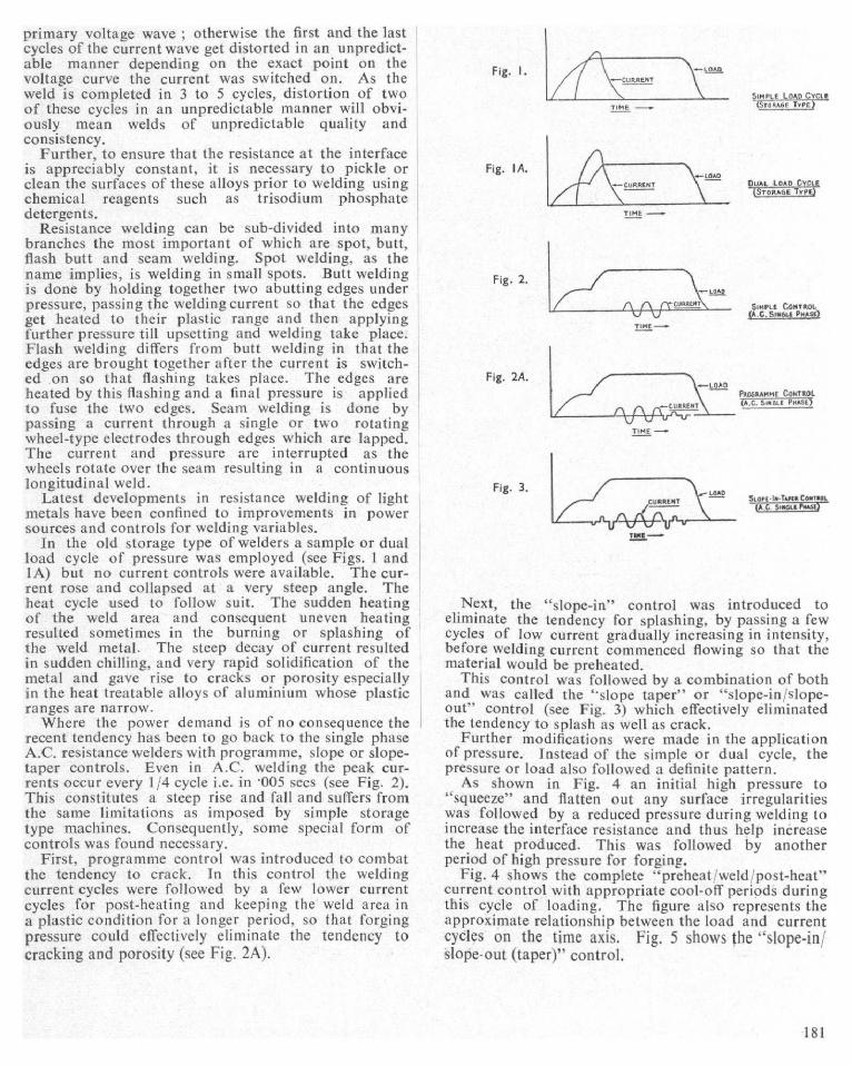
In the old storage type of welders a sample or dualload cycle of pressure was employed (see Figs. 1 andIA) but no current controls were available. The cur-rent rose and collapsed at a very steep angle. Theheat cycle used to follow suit. The sudden heatingof the weld area and consequent uneven heatingresulted sometimes in the burning or splashing ofthe weld metal. The steep decay of current resultedin sudden chilling, and very rapid solidification of themetal and gave rise to cracks or porosity especiallyin the heat treatable alloys of aluminium whose plasticranges are narrow.
Where the power demand is of no consequence therecent tendency has been to go back to the single phaseA.C. resistance welders with programme, slope or slope-taper controls. Even in A.C. welding the peak cur-rents occur every 1 /4 cycle i.e. in -005 sees (see Fig. 2).This constitutes a steep rise and fall and suffers fromthe same limitations as imposed by simple storagetype machines. Consequently, some special form ofcontrols was found necessary.
First, programme control was introduced to combatthe tendency to crack. In this control the weldingcurrent cycles were followed by a few lower currentcycles for post-heating and keeping the weld area init plastic condition for a longer period, so that forgingpressure could effectively eliminate the tendency tocracking and porosity (see Fig. 2A).
Fig. I.
TIME -
Fig. IA.
Fig. 2.
--LDAD---LUMREM7
SIMPLE LOAD CYCLESTORAGE TYPE)
DUAL LOAD CYCLE
(S roRAoE TYPE
SIMPLE CONTROL(A.G.SINALE PHASE)
TIME-
Fig. 2A.^LG^n
PROGRAMME CONTROL
AC. SINGLE HASECURRENT
TIME _
Fig. 3.
TINE -
SLOPE - IN-TAPIA CONTROL
A.C. SINGLE PHASE
Next, the "slope-in" control was introduced toeliminate the tendency for splashing, by passing a fewcycles of low current gradually increasing in intensity,before welding current commenced flowing so that thematerial would be preheated.
This control was followed by a combination of bothand was called the "slope taper" or "slope-in;'slope-out" control (see Fig. 3) which effectively eliminatedthe tendency to splash as well as crack.
Further modifications were evade in the applicationof pressure. Instead of the simple or dual cycle, thepressure or load also followed a definite pattern.
As shown in Fig. 4 an initial high pressure to"squeeze" and flatten out any surface irregularitieswas followed by a reduced pressure during welding toincrease the interface resistance and thus help increasethe heat produced. This was followed by anotherperiod of high pressure for forging.
Fig. 4 shows the complete "preheat weld'post-heat"current control with appropriate cool-off periods duringthis cycle of loading. The figure also represents theapproximate relationship between the load and currentcycles on the time axis. Fig. 5 shows the "slope-in;"slope-out (taper)" control.
181

Fig. 4.
Fig. S.
Fig. 6.
^^ ^ I YIEID^ .-LU11G
II1R[E Wi n V-1ABLE
r
I
Fig. 7.
wn. v+q^Ani Fx ESSURECv^ Ef'
FAF uEMLY CBM E lE*
DM MEAT gaAiAF \!/) IIBY$)---W,IMVAPIAPLE PRESSURE
CYEEE.
L AD
COWROLLED DECAY WAVE
FW!9ULNf.Y CI)MVERTER
( N. , ,
f
AM
PP
B LE Al EOYS)
It will be appreciated from the foregoing that thecontrols required for successful welding of aluminiumalloys especially of the heat treatable variety are verycomplicated indeed and are usually achieved by appro-priate electronic means.
A still later development is the frequency converter,3-phase, A . C. resistance welders . In these machinesall the 3 phases of an A.C. supply are made to passthrough a transformer which has a single secondarywinding . The A.C. lines are connected to the 3-phasetransformer windings through inversely connectedignitrons in pairs. By suitable controls the forwardignitrons are allowed to pass the first cycle of currentfollowed by the reverse ignitrons and by timing thisprocess it is possible to energise the welding trans-former secondaries with a current of low frequency,say, 12 per sec. or lower . These cycles have super-imposed on them a ripple , the frequency of which isthrice the supply frequency , for instance , 150 cyclesif the supply is at 50 cycles.
For welding aluminium and its non-heat treatablealloys a simple wave form as shown in Fig. 6 is usedbut for heat treatable alloys, a controlled decay waveas shown in Fig. 7 is employed . It will he observedfrom the figures that although the third harmonicripple of the 50 - cycle frequency is present , the currentnever touches zero but rises steadily and decays in
"IF -
EDRGE
a controlled manner. This current wave form is there-fore eminently suitable for weldirig aluminium andeven its heat treatable alloys.
Modern practice is to favour "slope-in taper" con-trolled single phase A.C. transformer; for welding thinsheets of aluminium if power problems are not import-ant and to go in for the costlier 3-phase frequency con-verters for thicker sections.
Inert gas shielded arc processes
The inert gas shielded arc processes are post-wardevelopments which have added remarkable impetusto the use of aluminium, magnesium and their alloysbecause they provide an Busy and reliable method forjoining these materials.
The outstanding feature of the inert gas shielded arcwelding processes is the complete absence of fluxes. Thisis possible because the action of the arc under properconditions removes the oxide film already present andthe shielding inert gas prevents its re-formation on themolten metal. Thus joints welded by inert gas archave better appearance, require no post-weld fluxremoval and usually require little or no finishingunless required dash. They alto have sounder struc-tures than welds normalIv made by other processes.Further, a high production rate is possible. the weldingspeed being 2 to 3 times faster than for steel of itsimilar thickness.
Tungsten inert gas process
The tungsten inert gas process hereinafter referredto as TIG process was the first one developed. In thisprocess an are is struck between a practically non-consumable tungsten electrode and the job to hewelded. The are is surrounded by an inert gas suchas argon or helium. The arc is used as heat source tomelt the parent material to he welded. A tiller metal,it' required, is added additionally into the molten poolas in gas welding.
Early experiments using O.C. for light alloys showedthat while positive polarity was required for disruptingthe oxide films present on them, it caused overheatingof the electrode which rapidly melted and disinte-grated.
Next A.C. was tried as the power source ; this alsowas found unsuitable because the positive half cycles soessential for the disruption of oxides were gettingsuppressed due to rectification. This rectification isinherent when an alternating Current arc is struck be-tween two dissimilar metals. To eliminate this inherentrectification a D.C. suppressor was developed. Thisconsists of a bank of A.C. electrolytic condensers(usually of about 33.000 \1 FD in capacity for 300 ampswelding current) which is connected in series in thewelding circuit. It was observed that this deviceenabled perfect welds to be made on light alloys byTiG welding.
Another device required to ensure easy striking ofthe arc and stability in welding is the high frequencyunit. This unit merely superimposes an HF current,
182

about 50 kilo cycles in frequency, over the weldingcurrent at a voltage of about 3,000 and helps toinitiate the arc even before the tungsten electrodetouches the work.
This high frequency unit however is likely to inter-fere with radio and television reception and has in morerecent years been superseded by a surge injector.
The surge injector controls an arc starter whichproduces sparks of high frequency high voltage to startthe arc and as soon as the arc is struck a relay recon-nects the circuits so that the surge injector producesa surge voltage of about 300 every time the current ispassing through zero after the negative half cycle.This enables the arc to be restruck without any delayduring the positive half cycles and thus helps to stabi-lise the arc. The use of this device enables transfor-mers of it low open circuit voltage, say, 50 volts to beemployed. With the HF unit described before, forwelding aluminium and magnesium alloys by TIGprocess, an open circuit voltage of 90 or 100 isrequired.
Tungsten electrodes which are comparatively costlyget contaminated if an are is started by the usualmethod of jabbing or striking it on the job to bewelded. Therefore the use of HF unit or surge injectorwith an A.C. or D.C. power source is imperative sothat an arc can be established by the ionisation createdby the passage of HF sparks even when the electrodeis, say, 1/8" away from the work piece.
The use of I to 2% zirconia or thoria in tungstenhas been found to help initiation and maintenance ofthe are and nowadays pure tungsten electrodes areseldom used.
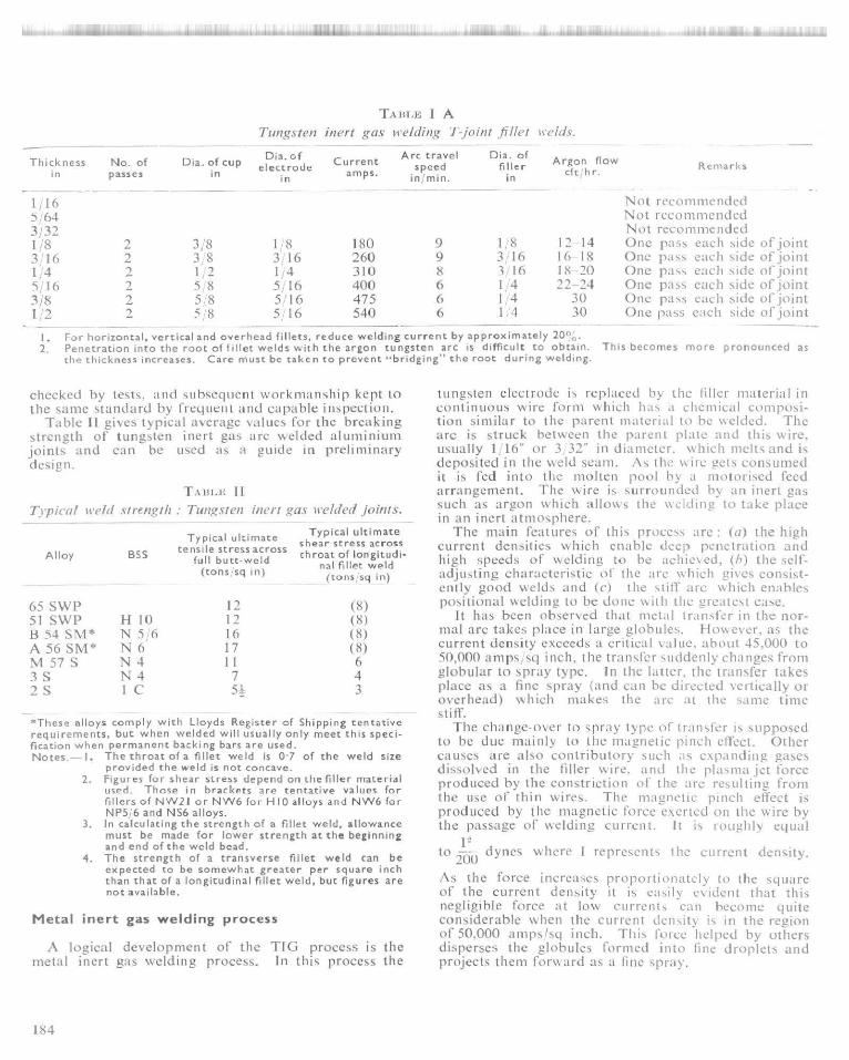
Given in Tables I and IA are the typical weldingconditions for manual TIG welding of aluminium.
To summarise, to weld light alloys by TIG process,an A.C. power source, a D.C. suppressor unit and ahigh frequency or surge injector unit are requiredbesides the welding torch and argon or helium gas.Argon is preferred to helium because of its readyavailability and its better are characteristics. Furtheran are struck in argon has better oxide scavengingproperties and, being a heavier gas, the flow required toget effective shielding is very much less than that forhelium.
Strength of tungsten inert gas arc weldedaluminium and its alloys
Strength of any particular welded joint will dependon several factors including the skill of the welder andthe size of the pieces being joined. The welder's skillinfluences the quality of the weld and this as well asthe size of the weld required affect the amount of heatput into an assembly and consequently the extent ofannealing and weakening of the parent material. Thuswhen high quality joints are a critical requirement, theweld stresses should preferably be established and
TABLE
Tungsten inert gas we/ding flat NO itelds without backing,
Thicknessin
Root Dia. of cupNo. of Edgepasses preparation opening in
in
Dia. ofelectrode
in
Currentamps
Arc travelspeedin'min
Dia. of fillerin
Argon flowcft,hr
1/32 1 30° 3/8 1/16 30 18 8flange
Recommended only for specialapplications
3/64 1 (a) 3/8Recommended only for specialapplications
3,'32 75 18 3/32 10
1/16 I (a) 3/8 3 32 90 13 3/32 12-145 64 1 (a) 3/8 3/32 115 12 1;'8 12-143/32 1 (a) 3/8-1/2 1/8 135 12 1/8 12-141/8 1 (a) 3/8-1/2
2 (rev)1/8 160 12 1/8 12-14
3,16 1 (b) 0-3 32 1/22 (rev)
3'16 230 11 3116 16-18
1 /4 1 (b) 0-3;32 1/22 (rev)*
3;16 270 11 3/16 18-20
3/8 1 (b) 0-3/32 1/2-5r8 1/4 360 9 1/4 2023 (rev)*
1/2 1 (b) 0-3.32 3/4 5 16 400 9 1 4 302 5/16 480 1/4 303 (rev)* 5/16 480 1/4 30
Square butt. (b) 60.'70 included angle . Single V preparation.Reverse side back -chipped and last pass completed with addition of filler.
183
LY0.. .4. 1, .., dlr+l: r+^:.®,.r rrrtA^.:
TA BLE I A
Tun,t,rsten inert gas lie/corm g T-joint fillet tie/dc,
Thickness No. of Dia. of cupin passes in
1,165/643j321rS3 161 45 1 63i81:2
1.2-
Dia. ofelectrode
in
Currentamps.
Arc travel Dia. ofspeed fillerin; min. in
2 3/8 I K 180 9 1,82 3 8 3 16 260 9 3162 1 2 1 4 310 8 3 162 5 8 5 16 400 6 1 42 58 5r 16 475 6 142 58 516 540 6 1l4
Argon flowcfthr.
12-1416 1818-2022-24
3030
Remarks
Not recommendedNot recommendedNot reconlnlendedOne pass each side of jointOne pass each side of jointOne pass each side of jointOne pass each side of jointOne pass each side of jointOne pass each side of joint
For horizontal , vertical and overhead fillets, reduce welding current by approximately 20%.Penetration into the root of fillet welds with the argon tungsten arc is difficult to obtain. This becomes more pronounced asthe thickness increases . Care must be taken to prevent -bridging " the root during welding.
checked by tests, and suhsequent workmanship kept tothe same standard by frequent and capable inspection.
Table 11 gives typical average values for the breakingstrength of tungsten inert gas are welded altllllillittilljoints and can he used as a guide in preliminary
design.
T:s nr.r: I
Tlpical held strength : Tungsten inert
Alloy BSS
,t-a.s welddc'd joints.
Typical ultimateshear stress acrossthroat of longitudi-
nal fillet weld(tons sq in)
Typical ultimatetensile stress across
full butt-weld(tons sq in)
65 SWP 1251 SWP H 10 12B 54 SM* N 5/6 16A56SM* N6 17M57S N4 113S N4 7
,2S I C 5!
(8)(8)(8)(8)643
*These alloys comply with Lloyds Register of Shipping tentativerequirements , but when welded will usually only meet this speci-fication when permanent backing bars are used.Notes.- I. The throat of a fillet weld is 0.7 of the weld size
provided the weld is not concave.2. Figures for shear stress depend on the filler material
used . Those in brackets are tentative values forfillers of NW21 or NW6 for H 10 alloys and NW6 forNP5 6 and NS6 alloys.
3. In calculating the strength of a fillet weld, allowancemust be made for lower strength at the beginningand end of the weld bead.
4. The strength of a transverse fillet weld can beexpected to be somewhat greater per square inchthan that of a longitudinal fillet weld, but figures arenot available.
Metal inert gas welding process
A logical development of the TIG process is themetal inert gas welding process. In this process the
tungsten electrode is replaced by the tiller material incontinuous wire form which has a chemical composi-tion similar to the parent material to he welded. Thearc is struck between the parent plate and this wire.usually 1, 16" or 3 32" in diameter. which melts and isdeposited in the weld seam. As the wire gets consumedit is fed into the molten pool by a motorised feedarrangement . The wire is surrounded by an inert gassuch as argon sshieh allows the welding to take placein an inert atmosphere.
The main features of this proce-ss are : (a) the highcurrent densities which enable deep penetration andhigh speeds of welding to he achieved, (h) the self-adjusting characteristic of the are which gives consist-ently good welds and (e) the stiff arc which enablespositional welding to be done s%ith the greatest ease.
It has been observed that metal transfer in the nor-mal are takes place in large globules. However, as thecurrent density exceeds a critical value, about 45,000 to50,000 anlps_sq inch, the transfer suddenly changes fromglobular to spray type. In the latter, the transfer takesplace as a tine spray (and can he directed vertically oroverhead) which makes the arc at the same timestiff.
The change-over to spray type of transfer is supposedto he due mainly to the magnetic pinch cll'ect. Othercauses are also contributory such as expanding gasesdissolved in the tiller wire. and the plasma jet forceproduced by the constriction of the are resulting fromthe use of thin wires. The magnetic pinch effect isproduced by the magnetic force exerted on the wire bythe passage of welding current. It is roughly equal
to dynes where I represents the current density.
As the force increases proportionately to the squareof the current density it is easily evident that thisnegligible force at low currents can become quiteconsiderable when the current density is in the regionof 50.000 anlpslsq inch. This force helped by othersdisperses the glohu[es formed into fine droplets andprojects them forward as a fine spray.
184
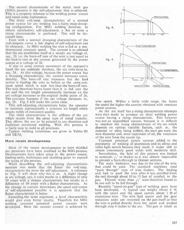
The second characteristic of the metal inert gas(MIG) process is the self-adjustment that is achieved.This is a nroperty inherent to the welding power sourceand needs some explanation.
The static volt amp. characteristics of a normalpower source for arc welding has a fairly steep droop-ing configuration. For MIG welding however, toobtain satisfactory self-adjustment, a flat or even arising characteristic is preferred. This will he dis-cussed later.
Even with a normal drooping characteristic of thevolt/ampere curve a fair degree of self-adjustment canbe obtained. In MIG welding the wire is fed at a pre-determined constant speed. The current is so selectedthat the arc establishes itself at a steady arc voltage of,say, 26 i.e. the burn-off rate of the wire is just equal tothe feed-in rate at the current generated by the powersource at a voltage of 26.
If due to some uneven movement of the operator'shand the arc suddenly shortens. the arc volts drop to,say, 24. At this voltage, because the power source hasa drooping characteristic, the current increases consi-derably. The burn-off rate increases but the feedmotor is feeding the wire as before at the same con-stant speed which is now less than the burn-off rate.The wire therefore burns faster than it is fed into thearc and the arc length automatically increases i.e. thearc voltage increases to the original stable point of 26.The converse happens if the arc voltage increases to,say, 28. Fig. 8 will make this point clear.
This self-adjusting characteristic helps the operatorto maintain automatically a constant arc length whichmeans welds of consistent quality.
The third characteristic is the stiffness of the arewhich results from the spray type of metal transfer.This allows the arc to be pointed in any direction andfacilitates positional welding. With this process itis fairly easy to weld in all positions.
Typical welding conditions are given in Tables IIIand 11I(A).
More recent developments
Most of the recent developments in inert shieldedare processes have been confined to the MIG process.Developments have taken place in the power source,feeding units, techniques and shielding gases to expandthe scope of the process.
While describing the self-adjusting characteristicsmention was made that the flatter the volt'amp.characteristic the more the self-adjustment. A referenceto Fig. 9 will show why this is so. A slight changein are voltage, say, 4 volts results in a difference of only20 amps with a steeper characteristic but results in adifference of 50 amps with a flatter characteristic. Asthe change in current determines the speed and extentof self-adjustment possible it is apparent that theflatter characteristic is better.
Extending the same argument, a level characteristicwould give even better results. Therefore for MIGwelding, constant potential power sources weredeveloped. Here the current control is achieved by
Fig. B.
Fig. 9.
STEEP CHARACTERISTIC
VARIATION 20AMPS. VARIATION = 50 AMPS.
FLAT CHARACTERISTIC.
+OL O0 ) }^ 3aT^ 40DAMPS
wire speed. Within a fairly wide range, the fasterthe speed the higher the current obtained with constantpower sources.
As the arc itself has a rising characteristic attemptswere then made to produce an ideal welding powersource having it rising characteristic. This howeverwas not an unqualified success because it is difficultto simulate the rising characteristic of the arc whichdepends on various variable factors, such as, thematerial or alloy being welded, the inert gas used, thewire diameter and, most important of all, the extensionof the wire from the nozzle tip.
Constant potential power sources added to thepopularity of welding of aluminium and its alloys andother light metals because they made it easier still toobtain consistently good welds with moderate skill.
Nevertheless, the field of this process was limitedto materials ;,;" or thicker as it was almost impossibleto prevent a burn-through in thinner sections.
The main limitation was due to the size of the wirethat could be used. The standard machines used`'push through" type of wire feeders. The feedingunit had to push the wire after it was unrolled fromthe reel through about 10 to 15 feet of conduit to thegun. Thinner wires than A't" were therefore found tobe too soft to be fed through.
Recently "spool-on-gun" type of welding guns havebeen developed. A typical one weighs about 4 lbwith the spool and the spool carries about 1 lb ofaluminium wire. The wire feed motor and the gearreduction units are mounted on the gun itself so thatthe wire is pulled directly from the spool a.id pushedthrough only 6 inches to the arc. The gun is rated at
OPERATING POINT.
185

Metal inert gas ee•elding :
Thicknessin
No. ofpasses
EdgePreparation
RootOpening
in
l h 1 3:'64
3JI6 I 1/162
114 1 40 included angle 1 162 Single V
5'16 I 40 included angle 3 322 Single V3
318 I 40' included angle 1,92 Single V3
1;2 12 40' included angle l;83 Single V4
TAxl.x 11I
Flat Nutt welds with temporar y backing.
NoseDia. offiller
Current Arc travels eed
Argonflow
inin
amps ip
n min cft hr
1 16 160 36 501 16 160 36 50
1.16 1.16 180 24 51)1,16 180 24 5()
1jl6 1 16 235 18 501;16 235 18 50
1'16 1 16 240 Is 501 16 240 15 501.16 240 18 50
1 16 1 16 240 12 501,16 240 12 501116 240 12 50
1 16 1,16 240 10 50[ r ] 6 240 10 501 116 24() IO 50t 16 240 10 50
TArII.F. III A
Remarks
No hack-chippingrequired.
Back-chip after 1stweld to sound metal,then complete lastpass.
After 2nd pass hack-chip and completeweld with last pass.
After 2nd pass back-chip and completeweld with last pass.
After 3rd pass back-chip and completeweld with last pass.
Metal inert gas welding : Flat and horizontal fillet n•elcls.
Thicknessin No. of passes Diameter of filler
inCurrent amps Arc travel speed
in minArgon flow
cftjhr
3 16 1 16 235 24 50114 1 16 245 16 505?16 1//16 245 14 5038 1 16 245 11 501,2 1,16 250 11 50
about 200 amps and is meant to handle wires 0.030"to ',;" at feed speeds of 100-900 inches per minute.
As the diameter of the wire could now be reducedto 0.030° the critical current required to obtain spraytype of transfer was reduced and therefore thinnergauge aluminium could be welded. Further becausethe gun is it self-contained unit it can operate at anydistance from the power source and therefore it can beused for welding awkward corners where accessibilityis limited.
Dip transfer
Another factor has contributed to the extension ofsemi-automatic are welding to thinner sections andthat is the recent development of the dip transfertechnique otherwise known as the "short arc" process.
It was observed that below 200 amps an entirelydifferent type of transfer to either globular or spraytype described above can occur if the are length wassufficiently short and the power source had certainspecial characteristics.
In this type of transfer the tip of the electrodeactually dips into the pool of molten metal on theplate surface causing a short circuit of the power sourceof sufficient duration to extinguish the arc. This shortcircuit results in an increase in welding current whichheats tip the electrode tip so that it melts off andbreaks and the arc is re-established. The processrepeats itself rapidly.
It is evident that for the process to repeat itselfrapidly the short circuit current must be sufficientlylarge and the build-up of such currents fast enough,i.e. the inductance of the power source must he low.
186

At the same time the inductance should not be so lowthat the response is too fast in which case it highpeaked short circuit current builds up and the arcgets re-established with explosive violence blowing offthe molten pool. Evidently the correct amount ofinductance is necessary. To meet this condition newtypes of metal rectifiers have been built having aslightly drooping characteristic, the slope of which(the slope of volt amp curve) can be controlled. Astandard rectifier available has a controllable droopingcharacteristic ranging from 2 volts per 100 amps to15 volts per 100 amps. The operator can thereforeselect the best volt/amp characteristic for a particularapplication.
It has been found that for the best welding per-formance a short circuiting cycle of 50-200 times persecond is ideal. Such arcs are very short indeed(14-19 volts as against 22-28 volts for spray transfer).The arc force is so reduced that it is possible to toleratefit-up gaps greater even than the plate thicknesses incertain cases and to weld exceptionally thin materials.Positional welding also becomes very much easier.
Thus with the gun mentioned above and 0.030"aluminium wires using dip transfer it is possible evenfor a welder of average skill to weld 1; 16" aluminiumin all positions. The welds may be produced veryfast. For instance, it is possible to weld 16 swg alu-minium at speeds in excess of 100 inches per minuteand 10 swg up to 72 inches per minute.
High current welding
Just as there was a limitation to the lower range ofcurrents, MIG welding of aluminium could not becarried out with higher amperages. For instance, usingaluminium wires 3 32" in diameter currents in excessof 400 amps produced extremely unsatisfactory welds.The weld pools were overagitated by the high arcforces and resulted in tunnelling, severe oxide folds andporosity. If this 400 amp limit could be exceeded itwas apparent that it would be possible to weld heavyplates in fewer passes. Also the additional input ofheat would tend to reduce the porosity because anyporosity forming gas would have sufficient time tobubble out before freezing occurred.
Recently however by careful control of variables ithas been possible to exceed this current limit and yetobtain satisfactory welds.
The welding torch should be able to pass 80 to 100cft of argon without excessive turbulence. The weldingwire must be free from foreign material. The edgesof aluminium prepared for welding must be cleaned byremoving the surface metal in which grease from themachining operations may have become embedded.Perhaps in the past too little attention was paid tothe surface condition of the edge and the wire. Anadditional shield through which extra argon can bepassed also helps to produce satisfactory welds.
Another important factor perhaps is the recentdevelopment of the slope controlled rectifiers as thepower source which, as stated earlier, allows theoperator to select the desired volt amp characteristics
to suit the particular application. Whatever may havebeen the contributory factors it is well known nowthat high current welding can be done on aluminium,reducing the cost of welding not only because of thefaster speeds possible but also because of the savingin edge preparation.
Automatic and mechanised shieldedarc welding processes
TIG and MIG welding can easily be adapted formechanised welding. By mounting the respective handwelding torches on an electrically driven tractor it ispossible to obtain extremely satisfactory mechanisedwelds for certain applications. For TIG welding anadditional wire feed unit can be attached so that thefiller wire is fed in by mechanised means. The arclength however will have to be controlled by theoperator if there are undulations on the plate.
In mechanised MIG welding due to the self-adjustingcharacteristic the arc length is fairly constant but forreally automatic control of arc length other means aremade use of.
For TIG welding a servo-synchronous control drivesa reversible motor which adjusts the height of thewelding torch. The are voltage which. can be presetis compared with a reference voltage. The differenceor the ERROR voltage is amplified and made todrive the height adjusting motor which either lifts thetorch or lowers it until the "error" voltage is zero. Thevoltage can be maintained consistently constant. Afiller wire attachment if desired completes the auto-matic welding set-up. The control described aboveis called the Automatic Arc Length Control and isachieved by electronic means.
For MIG welding the speed of the feed motor isgenerally controlled either by the arc voltage itself orby an electronic system which senses the arc voltageand drives the feed motor faster or slower so that thepresent arc length is maintained.
Automatic inert gas shielded welding eliminates thehuman factor from welding and makes it possible toobtain consistently good welds on aluminium andother metals.
Inert gas shielded spotwelding
MIG
This process was commercially introduced in 1954for carbon steels and stainless steels but was notrecommended for aluminium because of the difficultyin getting consistently good spot welds. The troublewas mainly due to the difficulty in getting a good startevery time. Subsequent work has proved that for agiven wire there is a voltage and current range withinwhich reasonably good starting can he obtained.Table IV gives an approximate idea of these figures.
It is easier to obtain a weld when joining a thinnersheet to thicker material if welding can be done fromthe thinner side.
187

TABLE IV
Metal inert gas spot welding starting requirements.
Aluminium alloyf,116 in dia.
filler wire (BSS)Volt
G1C 2528
NG21 24-27NG5 24
28NG6 24
28
Minimumcurrent, amps.
180200130360400400250
MIG spot welding can also be used for plug weldingof aluminium but is limited to a maximum of 3;'16"thick material. This limitation is imposed by thetendency to develop cold laps at the bottom of plugholes. Even today the process is not very satisfactorilyused for spot welding aluminium where high qualityand consistency are the primary criteria.
TIG
Tungsten inert gas spot welding of aluminium andother light metals have been to date not very satisfac-tory. Because high currents were required to melt thetop plate and subsequently the bottom one, for weldingaluminium, positive polarity on the electrode couldnot be used, while with D.C, negative polarity, theoxides, especially at the interface, did not get scaveng-ed. Arc striking was comparatively easy.
Recently some development has taken place usingD.C. negative polarity and clean, pickled sheets ofaluminium, with high purity argon shielding and poin-ted thoriated tungsten electrodes. Under laboratoryconditions consistently good welds have been producedbut commercially the process has not yet beenaccepted.
Tungsten arc cutting and theplasma torch
Ability to cut a metal easily plays an important partin fabrication work and therefore contributes to theease of welding and in turn to the popularity of themetal concerned. Site cutting, bevelling and shapingaluminium are not as easy as on mild steel which isamenable to gas Cutting.
Recently a great advance has been made in adaptingplasma torches and tungsten arc cutting, which usesa form of this plasma torch, has been developed.
In this process an arc is struck between the tungstenelectrode and the aluminium plate to be cut. The arcis constricted and made to pass through a water coolednarrow orifice. A shielding gas such as a mixture ofargon/hydrogen (25-75%) or nitrogen,' hydrogen (25-751,(',) is used. The arc, when constricted, producesa high temperature high velocity plasma jet. The
shielding gas is propelled forward at very great speedsand while the resulting temperature melts a narrowportion of the plate to be cut. the resulting kineticenergy of the plasma jet cuts the metal neatly byblowing away the molten metal. The surface pro-duced is clean and free from oxides and dross. Speedsof cutting of 100-150" per minute are possible on1 2" thick aluminium (250"'min on 1,4" ; 30 to 50";'min on 4j" thick plates).
This is a patented process and has not yet been intro-duced in India. Although machine cutting is preferred,hand cutting can also be done with a bit of' skill. Thisprocess when it gets wider publicity and attainspopularity, will surely prove a boon to the aluminiumfabricator.
Titanium
Titanium is a metal which has gained commercialimportance in recent years. This is mainly due to itsspecial properties such as its high strength, corrosionand heat resistance. etc., which arc of prime importancein modern technology relating to rocket and jet power-ed engines.
The difficulty in welding titanium is due to its prone-ness to absorb oxygen, nitrogen and to some extenthydrogen from the welding atmosphere and get embrit-tied. Therefore the more common methods of fabri-cation such as gas or arc welding cannot he employed.
Spot welding can be done easily but for large fabri-cation work inert gas shielded arc processes areemployed.
Both TIG and MIG welding can be used althoughthe latter requires special wires. However TIG weldingis the most popular in conjunction with D.C. powersources.
Tugsten inert gas (TIG) welding with a normal torchis unsatisfactory because the argon shielding from anormal shield is insufficient to protect the metal heatedabove the critical temperature both ahead and behindthe molten pool. Therefore special shields havingadditional trailing and leading covers are employed.A larger area of the seam is thus protected and shieldedduring the period when it is hot enough to absorboxygen and nitrogen from the atmosphere. To pro-tect the underside, similarly, a backing groove whichis flushed with pure argon is employed.
Where a titanium or its alloy component has tomeet critical conditions even this method of weldingis not quite satisfactory. Therefore special inert gaschambers are used for welding such items. A glovedcompartment which can be evacuated is resorted to.Where evacuation is not possible flushing out for afairly long period with pure argon can he done althoughthe results obtained are not as satisfactory.
The articles to be welded are put inside the compart-ment which is then evacuated and flushed with pureargon. The operator standing outside, welds thematerial by putting his hands through the gloves. Anobservation window allows him to watch the pool andmanipulate the torch and wire as desired.
Excellent welds in titanium are obtained by these
188

processes and the metal and its alloys are beingincreasingly employed where their special propertiesmake them the best choice.
Future developments
Atomic energy and nuclear power stations haverecently made popular the use of light metals and theiralloys. As stated in the beginning, the ease with whichthese could be welded, thanks to the recent develop-ments in the field of inert gas shielded processes, hasplayed a very important part in the popularity thesemetals and alloys have gained in the recent past.
Developments in regard to better and cheaper shield-ing gases or mixtures of shielding gases may be expect-ed in the near future. Better and easier methods ofof fabrication may yet be developed such as, for ins-tance, ultrasonic welding or electron beans weldingwhich are at present in their infancy.
Mr. S. C. Bhalla, NML: I would like to know if itis possible to use a cheaper gas, such as C02, instead ofhelium or argon for TIG welding.Mr. J. A. Mulivil (Author): In tungsten are process, acompletely chemically non-reactive gas has to beemployed, the principle being to exclude N2 and O.from the welding zone. There are several other inertgases no doubt. But carbon dioxide is a highly reactivegas at the are temperature and dissociates into carbonmonoxide and oxygen in the are ; the oxygen combineswith metals such as aluminium to form oxides, whichis very undesirable. Nitrogen is one of the gases whichcan be used for welding copper but unfortunately evennitrogen is not good enough for aluminium, the reasonbeing that nitrogen being a diatonic gas, dissociatesinto atomic state at the are temperature and becomeshighly reactive and forms nitrides with aluminium.However, for welding copper, nitrogen has been founduseful. There are other rare gases like Kr, Xe, Ne.It can be naturally expected that these gases are equallyeffective but they are available in such small quantitiesthat it would not he economical or commerciallypossible to use them.Mr. U. P. Mullick, Institution of Consulting Engineers,Calcutta : I would request the author to give a compa-rative cost data for using welding per It run by gas weld-ing, resistance welding and plasma torch method as wellas the cost of electrodes regarding light metal welding.Mr. J. A. Mulivil (Author) : I have not worked out
Conclusion
In the foregoing paragraphs an attempt has beenmade to outline briefly the recent developments in thefield of joining light metals and alloys. Although thedetails are not necessarily complete it is hoped that afairly comprehensive survey has been effected.
Acknowledgements
The writer is indebted to various magazines on weld-ing for some of the information and data contained inthis paper. He takes this opportunity to acknowledgethese with thanks. He also thanks his colleagues forthe help they have rendered in editing this paper.
Finally, he thanks the Directors of Indian OxygenCompany Ltd. and the organisers of this Symposiumfor allowing him this opportunity to present thispaper.
DISCUSSION
the cost figures but it is a well known fact that resis-tance welding is the cheapest as far as running costs areconcerned as the cost comprises only labour andelectrical energy consumed. However, the capital out-lay involved in installing an electrical resistance weldingmachine of the complicated type required for weldingof aluminium is considerable and depreciation alonewill form a large percentage of total costs. Cost ofwelding of aluminium by gas and argon arc processes,depends to a large extent on the availability of mate-rials in India. Even in other countries where argongas and the necessary equipment are readily available,the cost of welding of aluminium by the argonarcprocess is not as cheap as by gas welding. This ismore pronounced in India where gas welding is alreadypopular while the argonarc equipment and, till re-cently, even argon had to be imported.
But as I have already said there are limitations towelding of aluminium by gas and it is not possible touse corner or fillet welds. This naturally imposesseveral limitations on the designers. Many fabrica-tors, therefore, prefer to pay a little higher for argonarcwelding and use that process for joining aluminium.
In view of the foregoing, f estimate that in India thecosts of argonarc welding will work out to I timesthe cost of gas welding.Mr. R. ChouheI,, NMI_ : I would like the author togive the relative advantages of the tungsten electrodeprocess in the inert arc welding processes.
189

Mr. Afuliril (Author) : The two processes are comple-mentary to each other. Till recently before the FineWire are welding process was developed, there wasdefinite demarcation of thicknesses that could hewelded with the two processes. Inert gas metal arcprocess, due to its high current densities, naturallycould not he used for gauge materials. Therefore itwas restricted to thicknesses of 3 16" and over.Tungsten are process was used for welding of thinsheets as one can use 20 amps or even lesser currents.This is the main difference. Where it is possible to useboth processes, there are, of course. many advantagesin using metal inert ,as welding. compared to tungsteninert gas welding since metal inert gas welding is muchfaster and cheaper and easier to operate. With theadvent of the fine wire welding process, the inert gasmetal arc welding process is gaining further in popu-larity as it enables gauge thicknesses also to be weldedin all positions.Mr, S. C. Blialla, NAM-: I Would request Mr. Shankarto let us know how the weldability of light alloys aredetermined and also of the various problems encounter-ed in Welding in Hindustan Aircraft Ltd.Mr. U. P. Mullick, institution of Consulting Eii<,ineers,Calcutta : Mr. Shankar may also let us know thedetails of testing the welded joints in regard to tensile,compression and torsion strengths for plain sheet andlump piece welds ; and whether any chart or tablesare followed or each welded joint is tested by practicalstrain tests.Mr. P. K. Chatterjee, T.D.E. (I'chic/es and Ett,Qg.),Ahmedabad: As the HAL are the largest users of thelight alloys of the heat-treatable type, viz. thecopper-hearing duraltunnl, Cu-Mg-Si alloys of theconventional composition and also the Zn-bearingalloys, which they use to quite a large extent, I wouldlike to know whether they are welding them, and if so,what special difficulties they are finding.
As Mr. Bhalla desired, I would also like to knowwhether Mr. Shankar could give us some method ofassessing a term which goes by the name of' weldahilityand eludes all evaluation. For example. there is ageneral rough test "Reeds-cracking test" for steel.For aluminium alloys. how could one assess andevaluate the term "weldahility".Mi•, Al. B. Shankar, Hindustan Aircraft Ltd., Bata>alot'e:Welding is a means of jointing metal parts or components which may he of same material composition orof different shapes or as lately of dissimilar composi-tions. "Weldahility" of light alloys is principallydetermined by their compositional characteristics whichin turn determine the non-heat treatability or otherwiseof the alloy. Most simply mentioned, the ultimatestrength and soundness of the welded structure is ameasure of weldahility. The design features and theextent of previous hot or cold working also determinethe suitability or otherwise of welding. Wroughtproducts Of the duralumin type of alloys (AI-Cu-Mg-Si) and the higher strength (AI-Zn-Mg) alloysused for long range aircrafts. are not recommendedfor welding. Also, even spot welding of duralumintype (2.1 ST) alloys is not recommended where corro-
sive conditions are encountered in service, Onlynon-heat treatable alloys are chosen for welding forsatisfactory service. As far as possible, no welding isconsidered in case of heat treatable alloys due touncertainties in obtaining utiilol-llllty of the structuralconstituents and strength continuity v,ith the parentmetal. However. some heat treatable alloys, at thehands of expert welders and with adequate pre-cautions can be welded with post-weld heat-treatmentas imperative.
All types of welding are undertaken at HAL. Theyare universally adopted for jet engine assemblies andto a very limited extent for aircraft skins (wings,tail units and fuselage). Lately in modern supersonicaircraft where light alloys are unusable, stainlesssteel skins and major assemblies are of weldedconstruction.
In general, welding is of the distinct types, namely,I ) fusion and (2) pressure or forge. in fusion a eldiir;^,
the method of heating is either by (a) gas. (h) elec-tric are or (c) chemical action (thermit).
In gas welding, oxy-acetylene or atomic hydrogenis used. To protect against any oxidising tendencies,in the former case fluxes for welding are usually em-ployed. The precautions to he taken in such casesare : (I) cleanliness of raying surf aces. (2) freedom fromadherent oxide coatings. and (3) careful removal offluxes or slags after welding, as. otherwise, their pre-sence would induce corrosion. In electric arc welding,tungsten or carbon rods as electrodes shielded by argonor atomic hydrogen. are used with filler metals.Pressure welding with electric resistance is anothermajor group, embracing spot seam, projection andflash-butt weldings.
The general defects that arise from welding arecracks (peripheral or internal), cavities, porosity over-lap. inclusions. metal expulsions. incorrect weld size,misalignment, inadequate penetration and fusion,under-cutting, surface burns. warpage. etc. There arenumerous difficult problems in welding which dailyarise in jet engine construction in HAL, which areovercome also in collaboration with the representativesof reputed firms like Rolls Royce. Bristols and Folland.
The modern trend is towards replacernent of weldedassemblies by integrated (forged and elaboratelymachined) parts as critical components of' the aircraft(such as spares, booms, etc.) with a view to eliminatethe uncertainties and defects associated with welding.
Mechanical tests, micro-examination and ^rlon-destructive (radiographic or ultrasonic) testing arccarried out on welded assemblies. As mostly weldingof light alloys is confined to sheet or plate products,samples are tested for tensile properties. The natureand location of fractures tell the story of the weld.The fractures through the weld or in the fusion zoneare indicative of defective welding. Further, disconti-nuity of weld structures, grain coarsening or burningeffects, oxide inclusions, cracks. lack of penetration,etc. are revealed in the micro-examination of weldsand adjacent areas. Non-destructive testing methodsthrow light on the internal soundness of the weld.Welded assemblies for critical parts for aircraft or jet
190

engine are tested under alternating stresses (Fatigueproperties), simulating service conditions or for creepproperties.
Strictly no weld-defects are tolerated. But in produc-tion small defects are inevitable and as costly man-hours cannot easily be set aside, welds are acceptedwith so-called "permissible" defects. In the aircraftindustry no compromises are allowed nor sought.The tolerance of "permissible" defects may lead towrong connotation and misjudgement by inexperiencedhands. It is advisable, therefore, to have the partsshowing even small defects, as far as possible, re-worked. Reverting a little to the so-called "permissible"
defects, I may state that peripheral cracks are moreharmful than internal cracks in welded parts sub-jected to dynamic stresses. A number of pin holeswide apart may be harmless but a few close ones in aline are dangerous.
As to the question of welding of "lumpy" parts,I may repeat that it is always advisable to prepare thefaying surfaces as geometrical faces prior to welding.Usually, welding is not resorted to in joining "lumps".Perhaps, the question pertains to salvaging of castingswith slight defects corrected by welding. The repairedcastings or fabricated parts are, invariably, radio-graphed for assurance of the soundness of the weld.
191