Embed Size (px)
Citation preview
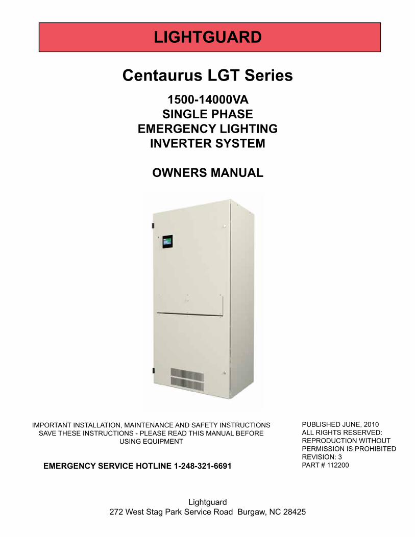
Centaurus LGT Series1500-14000VA
SINGLE PHASEEMERGENCY LIGHTING
INVERTER SYSTEM
OWNERS MANUAL
PUBLISHED JUNE, 2010ALL RIGHTS RESERVED:REPRODUCTION WITHOUTPERMISSION IS PROHIBITEDREVISION: 3PART # 112200
IMPORTANT INSTALLATION, MAINTENANCE AND SAFETY INSTRUCTIONSSAVE THESE INSTRUCTIONS - PLEASE READ THIS MANUAL BEFORE
USING EQUIPMENT
Lightguard272 West Stag Park Service Road Burgaw, NC 28425
EMERGENCY SERVICE HOTLINE 1-248-321-6691
LIGHTGUARD


INTRODUCTION.....................................................................................................................4-6RECEIVING THE INVERTER.................................................................................................7-8INSTALLATION
INSTALLATION PRECAUTIONS..............................................................................................9TOOLS REQUIRED AND INSTALLATION CHECKLIST.......................................................................10AC INPUT BREAKER, WIRING AND CURRENT MATRIX.................................................10AC OUTPUT BREAKER, WIRING AND CURRENT MATRIX.................................................11CABINET DIMENSIONS, ACCESS AND CLEARANCES...........................................................12-15BATTERY INSTALLATION..........................................................................................16-19BATTERY WIRING...........................................................................................................20-25INPUT AND OUTPUT CONDUIT ENTRY POINTS..........................................................................................................26INPUT AND OUTPUT WIRING...................................................................................................................27-28
COMMUNICATIONSSTANDARD MONITOR...............................................................................................................29INTELLISTAT TSTM MONITOR...........................................................................................................30
START UP PROCEDURE.....................................................................................................................31-32OPERATION
STANDARD MONITOR...................................................................................................................33-34INTELLISTAT TSTM MONITOR......................................................................................................35-48
BYPASS SWITCH.....................................................................................................................49MAINTENANCE PROCEDURES...........................................................................................50-53SPECIFICATIONS...............................................................................................................54-58WARRANTY..............................................................................................................................59CUSTOMER SUPPORT............................................................................................................60
APPENDIX A.........................................................................................................................................A61
CABINET OUTLINE ............................................................................................................A62-A65COMPONENT LOCATION DIAGRAM..............................................................................A66-A67ONE LINE DIAGRAM...................................................................................................................................A68SYMBOLS... . . . . . . . . . . . . . . . . . . . . . . . . . . . . . . . . . . . . . . . . . . . . . . . . . . . . . . . . . . . . . . . . . . . . . . . . . . . . . . . . . . . . . . . . . . . . . . . . . . . . . . . . . . . . . . . .A69
CONTENTS

Page 4
INTRODUCTION
This specification defines the electrical and mechanical characteristics and requirements for the single phase, on line, double conversion, Uninterruptible Power System (UPS) for Emergency Lighting applications. The inverter shall be an Insulated Gate Bipolar Transistor (IGBT), Pulse Width Modulation (PWM) inverter, microprocessor controlled, transistorized, solid-state uninterruptible power supply. The inverter shall work in conjunction with the existing electrical system to provide high quality AC power for critical emergency lighting and other safety equipment.
The inverter system shall consist of a charger, battery, inverter, protective devices, high speed static bypass transfer switch, synchronizing and phase lock circuitry, maintenance bypass switch and the controls required to provide regulated, continuous, conditioned power to emergency lighting loads.
Functional Description
Inverter
The inverter shall be a IGBT, PWM design, capable of delivering AC power within specified limits to the critical load bus. The inverter shall be microprocessor controlled and shall include all necessary protective devices and control circuits. Conditions beyond the specified limits of the PWM inverter shall cause the load to be automatically powered by the High Speed Static Bypass transfer switch.
High Speed Static Bypass Transfer Switch
An internally mounted High Speed Static Bypass transfer switch be shall be provided as an integral part of the inverter. The transfer switch shall be rated to conduct full load current continuously while in bypass mode.
SYSTEM OPERATION AND DESCRIPTION
Operational Modes
The inverter shall operate in a double conversion mode providing conditioned, regulated power to the emergency lighting loads.
A. Normal: The utility supply energizes the rectifier which converts it to DC power for the Inverter, which continuously supplies the load. The battery charger supplies the energy necessary to maintain the maximum charging level to the battery.
B. Emergency: Upon failure of the utility supply, the IGBT PWM inverter continues to provide conditioned power to the load using the battery as the source of power.
C. Return to normal conditions: When the utility supply returns within the tolerance limits, the inverter resumes normal operation. The battery charger automatically recharges the battery to ensure maximum battery run time in the shortest possible time.
D. Downgrade: If the battery is taken out of service for maintenance via the disconnect switch, the inverter continues to function but provides no backup protection.
GENERAL

Page 5
INTRODUCTION CONTINUED
MONITORING
General
The inverter unit shall incorporate the necessary controls, instruments and indicators to allow the operator to monitor the system status and performance, as well as take any appropriate action. The microprocessor control and diagnostic system shall perform a battery discharge test on a monthly basis. Results of the test shall be evident via the front panel display.
Display
Standard Display
The inverter shall have a grouped display, user friendly, mimic panel that provides the status of the system with LEDs and Icons.
The display shall provide visual indication for the following:
A. Line Voltage: Above normal limits Within normal limits Below normal limits
B. Static Bypass: Load on Static Bypass
C. Load: Percent load line one to neutral Percent load line two to neutral (on applicable models)
D. Battery: In use Percent Battery remaining Low Battery Check Battery
E. Alarm: Active
The system shall provide an audible alarm for the following conditions:
System on Battery Low Battery Check Battery Inverter Overload
The display shall include the following control functions:
ON push button, lighting inverter start Fail-Safe Dual OFF push buttons Alarm silence and Push to test button Battery Test

Page 6
INTRODUCTION CONTINUED
Display Continued
Optional Intellistat TSTM Monitor (available for 4.2KW-14KW only)
ADVANCED DIGITAL MONITORING - The user-friendly Intellistat TSTM monitor provides quick, full access to all of the monitor features, and also allows all programming to be done directly from the monitor. An easy to read LCD indicates all the electrical parameters, as well as the functional status of the inverter. A virtual keypad allows the entry of date / time values, system setpoints and password information into the monitor, without the need for an external computer and cable.
The Intellistat TSM - Intelligent status monitoring on an emergency lighting inverter’s operational status is critical for maintaining the building’s operational efficiency, as well as for monitoring the power feeding the lighting systems. With this in mind, the inverter is designed with state of the art monitoring features to provide complete system diagnostics and testing with access to all electrical system parameters.
- High / Low Input Voltage- High / Low Output Voltage- High Output Volt-Amperes- High / Low Output Frequency- High / Low Battery Voltage- High Battery Charge Current
FEATURES
INVERTER STATUS AND ALARM INDICATORS
- LCD display of all electrical parameters.- NFPA compliant automatic battery testing and logging.- User programmable automatic system testing.- System alarm annunciation.- Audible alarm with alarm silence.- Alarm status display.- Email / Cell phone status notification.- Optional fax / email / voice / web page reporting of test results.
- Date and time display.- Auto logging of test results / events.- Multi layer password protection.- Remote monitoring capabilities.- Programmable local interfaces.- Logs up to 50 events.- Non volatile clock and memory.- Programmable alarm set points.
- System Normal- General Alarm- System on Battery- Low Battery Warning- Low Battery Shutdown- Battery Test in Process
- Output Volt-Amperes- Output Watts- Output Power Factor
- Auto Battery Test Failed / Passed- Off Bus Status- Output Circuit Breaker Open- Charger Fail / DC Open Circuit- System in Static or Manual Bypass- REPO Active
MEASURED PARAMETERS
- Battery Charger Current- Battery Capacity Remaining
- Input Voltage- Output Voltage- Output Current
- Output Percent Load- Output Frequency- Battery Voltage
AUTOMATIC SYSTEM TESTS - The Intellistat TSTM Monitor automatically performs a user defined (date and time) 5 minute system test every 30 or 90 days; as well as a user defined (date and time) annual 30, 60 or 90 minute system test. For all of these tests, the Intellistat TSTM Monitor logs the test results with the date and time, as well as a “pass” or “fail” indication.
MANUAL SYSTEM TESTS - The Intellistat TSTM Monitor also allows the user to manually invoke a user defined system test for 30, 60, or 90 minutes. A 1 or 5 minute manual test is also available for “spot inspections”.

Page 7
RECEIVING THE INVERTER
RECEIVING YOUR INVERTER
INSPECTION, PLACEMENT, INSTALLATION, SETUP AND START-UP SHOULD BE PERFORMED BY QUALIFIED
PERSONNEL ONLY
INSPECTION
Upon receipt of your lighting inverter, visually inspect the unit(s) for shipping damage. If shipping damage has occurred, the purchaser should promptly notify the carrier and file a claim with the carrier. The factory should be notified if the damages may impair the operation of the unit. Reference front cover or accompanying paper work for factory contact information. DO NOT REMOVE THE DEBRIS SHIELD FROM THE TOP OF THE UNIT UNTIL READY FOR START UP.
Note: Open the front door of the enclosure(s) and inspect inside the unit for shipping damage.
STORAGEIf it is necessary to store the unit, be sure to place it in a clean dry area. For extended storage, the batteries must be charged for 24 hours every 6 months. Failure to do so will result in weak or bad batteries which WILL NOT be covered under the warranty. Charging is accomplished by installing the batteries, turning the inverter on and allowing it to run. See “Installation - Battery Installation” and “Battery Wiring” for details on installing batteries and the “Start-up Procedure” for turning the inverter on. While storing disconnect the battery connector from the inverter. Make sure proper ventilation is available any time the inverter is on.
IMPORTANT NOTICE
This shipment has been carefully inspected, checked and properly packaged at our company.
When it was delivered to the carrier it was in good condition and technically it became your property at that time. Thus, any damage, whether obvious or hidden, must be reported to the transportation company
within FIVE days of receipt of the shipment at your premises to avoid forfeiting claims for damages.
FOR ALL SHIPMENTS DAMAGED IN TRANSIT
Leave the items, packing material and carton “AS IS”. Notify your carrier’s local officeand ask for immediate inspection of the carton and contents.
After inspection has been made by the carrier, and you have received acknowledgment in writing as to the damage, notify our Customer Service Department to make any required repair arrangements.
It is your responsibility to follow the above instructions or the carrier will not honor any claims for damage. Also, if there are any shortages or questions regarding this shipment, please notify us within FIVE days.
Please note that we cannot be responsible for any service work or back-charges unless authorized by us in writing, before the work is performed.
WHILE IN STORAGE BATTERIES MUST BE CHARGEDFOR 24 HOURS EVERY 6 MONTHS. WHILE IN STORAGE
DISCONNECT THE BATTERY CONNECTOR FROM THE INVERTER.

Page 8
RECEIVING THE INVERTER CONTINUED
TOOLS REQUIRED:1/2” Socket, Forklift, dolly.
Batteries on same pallet as the lighting inverter
***CAUTION*** CABINETS AND BATTERIES ARE EXTREMELY HEAVY
USE PROPER EQUIPMENT WHEN REMOVING THE CABINETS FROM THE SKID
1. Remove the plastic wrapping and banding and discard.2. Remove batteries from pallet with the use of a dolly or other lifting device be sure to place them in a safe location.3. To remove the lighting inverter from the pallet, first remove the four 1/2” bolts that are securing the lighting inverter cabinet to the pallet.4. Using a forklift, place the forks securely under the lighting inverter from the front or back side.5. Carefully lift the lighting inverter from the skid.6. Set the lighting inverter cabinet down until you are ready for installation. Do not remove the debris shield from the top of the unit until ready for start up.
Batteries on different pallet as the lighting inverter or batteries installed internally:
1. Remove plastic wrapping2. To remove the lighting inverter from the pallet, first remove the four 1/2” bolts that are securing the lighting inverter cabinet to the pallet.3. Using a forklift, place the forks securely under the lighting inverter from the front or back side.4. Carefully lift the lighting inverter from the skid.5. Set the lighting inverter cabinet down until you are ready for installation.
REMOVING THE LIGHTING INVERTER FROM THE PALLET
*****SHOCK HAZARD*****DO NOT SHORT BATTERY TERMINALS

Page 9
INSTALLATION PRECAUTIONS
BATTERIES ARE VERY HEAVY. USE CAUTION WHEN LIFTING AND MOVING THEM. INSTALLATION SHOULD ONLY BE PERFORMED BY AUTHORIZED PERSONNEL.
DIAGRAMS FOR WIRING BATTERIES ARE SHOWN ON THE FOLLOWING PAGES. BE SURE TO WIRE BATTERIES PROPERLY. IMPROPER WIRING CAN CAUSE DAMAGE TO THE BATTERIES. WIRING
SHOULD ONLY BE PERFORMED BY AUTHORIZED PERSONNEL.
Only replace batteries with identical specification of original batteriessupplied with the system.
*****SHOCK HAZARD*****DO NOT SHORT BATTERY TERMINALS
USE CAUTION WHEN HANDLING OR SERVICING BATTERIES. BATTERY ACID CAN CAUSE BURNS TO SKIN AND EYES. IF ACID IS SPILLED ON SKIN OR IN THE EYES, FLUSH WITH FRESH WATER AND
CONTACT A PHYSICIAN IMMEDIATELY.
***** CAUTION *****Do not dispose of battery or batteries in a fire. The battery may explode.
***** CAUTION *****Do not open or mutilate the battery or batteries.
Released electrolyte is harmful to the skin and eyes. It may be toxic.
Servicing of batteries should be performed or supervised by personnelknowledgeable of batteries and the required precautions.
Keep unauthorized personnel away from batteries.
***** CAUTION *****
A battery can present a risk of electrical shock and high short circuit current. The following precautions should be observed when working on batteries:
1) Remove watches, rings, or other metal objects.2) Use tools with insulated handles.
3) Wear rubber gloves and boots.4) Do not lay tools or metal parts on top of batteries.
5) Disconnect charging source prior to connecting or disconnecting battery terminals.
- Follow all standard and local electrical codes. Be sure input power to UPS is properly grounded.- Do not allow water or foreign objects to get inside UPS.
- Do not place objects or liquids on top of the UPS.- Do not locate UPS near running water or where there is excessive humidity.
INSTALLATION PRECAUTIONS
DO NOT REMOVE THE DEBRIS SHIELD FROM THE TOP OF THE UNIT UNTIL READY FOR START UP.
This unit is intended for installation in a temperature controlled, indoor area free of conductive contaminants.

Page 10
INSTALLATION
_______ Flat Head Screw Driver, T handle allen wrench (for input breaker).
_______ The AC input breaker, wiring and amperage matrix defines the proper AC breaker size for each model. Refer only to the matrix for the service panel AC breaker size. The unit comes standard with terminals for hard wire installation.
_______ Lighting inverter systems require a ground wire. The ground wire should be the same size as the input feed wires (not required by code). The ground that feeds the lighting inverter should be of good integrity and dedicated to the lighting inverter. The run should be as short as possible. Conduit cannot be used for the grounding of the circuit.
_______ When wiring batteries be sure to use insulated tools for safety.Reference: NEC ARTICLE 250
NOTE: Input currents alone are maximum at full load, and when batteries are in recharge mode.
INPUT MATRIX (KVA=KW)
INPUT INPUT INPUT INPUT INPUT INPUT INPUT INPUT INPUTVOLTAGE CURRENT BREAKER CURRENT BREAKER CURRENT BREAKER CURRENT BREAKER
120V 22.1 25 26.7 35 39.4 50 45 50277V 9.8 15 11.9 15 17.1 25 19.5 25
120/208V ---- ---- ---- ---- 22.1 30 25.2 30120/240V ---- ---- ---- ---- 19.1 30 21.8 30
INPUT MATRIX (KVA=KW)
INPUT INPUT INPUT INPUT INPUT INPUT INPUT INPUT INPUT INPUT INPUTVOLTAGE CURRENT BREAKER CURRENT BREAKER CURRENT BREAKER CURRENT BREAKER CURRENT BREAKER
120V 49.6 70 57.6 80 ---- ---- ---- ---- ---- ----277V 21.4 30 24.9 35 32.4 50 36.8 50 39 50
120/208V 28.6 40 33.2 50 43.1 60 49 70 51.9 70120/240V 24.7 40 28.8 50 37.4 60 42.5 70 45 70
INPUT MATRIX (KVA=KW)
INPUT INPUT INPUT INPUT INPUT INPUT INPUT INPUT INPUT INPUT INPUTVOLTAGE CURRENT BREAKER CURRENT BREAKER CURRENT BREAKER CURRENT BREAKER CURRENT BREAKER
120V ---- ---- ---- ---- ---- ---- ---- ---- ---- ----277V 43.3 60 49.9 70 61.5 80 66 90 68.2 90
120/208V 57.7 80 66.5 90 80 100 85.9 125 88.8 125120/240V 50.1 80 57.6 90 69.3 100 74.4 125 77 125
480V ---- ---- ---- ---- 35.5 45 38.1 50 39.4 50
1.5KVA/KW 2.2KVA/KW 3KVA/KW 3.5KVA/KW
14KVA/KW
7.5KVA/KW4.2KVA/KW 5KVA/KW 6KVA/KW 7KVA/KW
10KVA/KW8.5KVA/KW 13.5KVA/KW12.5KVA/KW
AC INPUT BREAKER, WIRING AND CURRENT MATRIX
This unit is intended for installation in a temperature controlled, indoor area free of conductive contaminants.
TOOLS REQUIRED AND INSTALLATION CHECKLIST

Page 11
INSTALLATION CONTINUED
AC OUTPUT BREAKER, WIRING AND CURRENT MATRIX
1.5KVA/KW 2.2KVA/KW 3KVA/KW 3.5KVA/KW 4.2KVA/KW 5KVA/KW 6KVA/KWOUTPUT OUTPUT OUTPUT OUTPUT OUTPUT OUTPUT OUTPUT OUTPUT
VOLTAGE CURRENT CURRENT CURRENT CURRENT CURRENT CURRENT CURRENT120V 12.5 18.3 25 29.2 35 41.7 -----277V 5.4 7.9 10.8 12.6 15.2 18.1 21.7
120/277V * 12.5 / 5.4 18.3 / 7.9 25 / 10.8 29.2 / 12.6 35 / 15.2 41.6 / 18.1 50 / 21.7120/208V ------- ------- 14.4 16.8 20.2 24 28.8120/240V ------- ------- 12.5 14.5 17.5 20.8 25
7KVA/KW 7.5KVA/KW 8.5KVA/KW 10KVA/KW 12.5KVA/KW 13.5KVA/KW 14KVA/KWOUTPUT OUTPUT OUTPUT OUTPUT OUTPUT OUTPUT OUTPUT OUTPUT
VOLTAGE CURRENT CURRENT CURRENT CURRENT CURRENT CURRENT CURRENT120V ----- ----- ----- ----- ----- ----- -----277V 25.3 27.1 30.7 36.1 45.1 48.7 50.4
120/277V * 58.3 / 25.3 62.5 / 27.1 70.8 / 30.7 83.3 / 36.1 104.2 / 45.1 112.5 / 48.7 116.7 / 50.4120/208V 33.7 36.1 40.9 48.1 60.1 64.9 67.3120/240V 29.2 31.3 35.4 41.7 52.1 56.3 58.3
OUTPUT MATRIX (KVA=KW)
OUTPUT MATRIX (KVA=KW)
This unit is intended for installation in a temperature controlled, indoor area free of conductive contaminants.

Page 12
INSTALLATION CONTINUED
1.5KW - 3.5KWCABINET DIMENSIONS, ACCESSES AND CLEARANCES
Refer to the drawing below for installation clearances and ventilation requirements. The lighting inverter should be placed in a dry, well ventilated or temperature controlled area. Be sure not to block any fan or air inlet areas of the lighting inverter. Doing so will cause damage to the unit.
0.82234.146
71.895
3.000
EXHAUST AIR
AIRINLETS
1.935Ø 0.4384-PLACES
19.250
No
side access req
uired
WEIGHT WITHBATTERIES
1.5 - 2KW = 1091#3 - 3.5KW = 1256#
No
side access req
uired
DOOR SWING 35"
23.789
36.000
Minimum 12" clearancefor exit air flow and topfeed conduit entry / exit.
LIGHTING INVERTER PLACEMENT
This unit is intended for installation in a temperature controlled, indoor area free of conductive contaminants.

Page 13
4.2KW - 5KWCABINET DIMENSIONS, ACCESSES AND CLEARANCES
Refer to the drawing below for installation clearances and ventilation requirements. The lighting inverter should be placed in a dry, well ventilated or temperature controlled area. Be sure not to block any fan or air inlet areas of the lighting inverter. Doing so will cause damage to the unit.
LIGHTING INVERTER PLACEMENT
INSTALLATION CONTINUED
0.82234.146
79.895
3.000
1.935Ø 0.4384-PLACES
19.250
WEIGHT WITHBATTERIES
4.2KW = 1645#5.0KW = 1734#
SPEC
TAG
- RISK OF ELECTRICAL SHOCK-
HAZARDOUS LIVE PART INSIDE THIS UNIT ARE
ENERGIZED FROM THE BATTERY SUPPLY EVEN
WHEN THE INPUT AC POWER IS DISCONNECTED.
INTENDED FOR USE IN A
CONTROLLED ENVRONMENT.
CAUTION
EXHAUST AIR12" MINIMUM
AIRINLETS
No
side access req
uired
No
side access req
uired
DOOR SWING 35"
23.789
36.000
Minimum 12" clearancefor exit air flow and topfeed conduit entry / exit.
This unit is intended for installation in a temperature controlled, indoor area free of conductive contaminants.

Page 14
INSTALLATION CONTINUED
6KW-10KWWITH EXTERNAL BATTERY CABINET
DIMENSIONS, ACCESSES AND CLEARANCES
Refer to the drawing below for installation clearances and ventilation requirements. The battery cabinet should be placed in a dry, well ventilated or temperature controlled area. Be sure not to block any fan or air inlet areas of the lighting inverter. Doing so will cause damage to the batteries.
BATTERY CABINET PLACEMENT
1.749
27.14634.1463.000
0.822
79.895
1.935Ø 0.4384-PLACES
19.250
WEIGHT WITHBATTERIES
6.0KW-7.0KW = 2645#7.5KW-8.5KW = 2898#
10.0KW = 3298#
AIRINLETS
AIRINLETS
EXHAUST AIR12" MINIMUM
DOOR SWING 35"
65.000
23.789
29.00036.000
DOOR SWING 29" BATTERY CABINET
Minimum 12" clearancefor exit air flow and topfeed conduit entry / exit.
No side access required
No side access required
This unit is intended for installation in a temperature controlled, indoor area free of conductive contaminants.

Page 15
12.5KW-14KWWITH EXTERNAL BATTERY CABINET
DIMENSIONS, ACCESSES AND CLEARANCES
Refer to the drawing below for installation clearances and ventilation requirements. The battery cabinet should be placed in a dry, well ventilated or temperature controlled area. Be sure not to block any fan or air inlet areas of the lighting inverter. Doing so will cause damage to the batteries.
BATTERY CABINET PLACEMENT
INSTALLATION CONTINUED
23.790
12.418TYP.
8.000TYP.
Ø 0.43819.25034.146
3.000
0.822
79.895
1.93522.250
DOOR SWING 35"4.500TYP.
2.000TYP.
1.749
DOOR SWING 35"
34.146
72.000
26.789
36.00036.000
AIRINLETS
WEIGHT WITHBATTERIES
12.5KW = 4124#
14KW = 4576#
CAUTION- RISK OF ELECTRICAL SHOCK-
HAZARDOUS LIVE PART INSIDE THIS UNIT ARE
ENERGIZED FROM THE BATTERY SUPPLY EVEN
WHEN THE INPUT AC POWER IS DISCONNECTED.
INTENDED FOR USE IN A
CONTROLLED ENVRONMENT.
AIRINLETS
SPEC
TAG
AIR FLOW
8-PLACES
Minimum 12" clearancefor exit air flow and topfeed conduit entry / exit.
No
side access req
uired
No
side access req
uired
13.5KW = 4314#
This unit is intended for installation in a temperature controlled, indoor area free of conductive contaminants.

Page 16
INSTALLATION CONTINUED
BATTERY INSTALLATION 1.5KW - 5KW
1.000
(10) BATTERIESWIRED IN SERIES.
TYPICAL BOTH SHELVES
COMPLETELY SCREWTHREADED ROD INTO PANEL
UNTIL IT BOTTOMS OUTAGAINST CABINET.
TIGHTEN HEXNUT TO CHANNEL.
A
1/4-20 X 5/8"WITH LOCK, FLAT WASHER.3 PLACES
B
A
INSTALL HEXNUTON THREADED ROD1" FROM END
OPTIONAL EQUIPMENT
(only one shelf shown)
B
Battery Sizes 40, 55, 90, 100, 120, and 150 A/H
NOTE - NOT ALL BATTERY MANUFACTURERS WILL HAVE THE (+) AND (-) POSTS AS SHOWN BELOW. USE EXTREME CAUTION WHEN WIRING.
WARNING - DO NOT PLUG IN DC CONNECTOR UNTIL READY TO APPLY AC POWER.

Page 17
INSTALLATION CONTINUED
BATTERY INSTALLATION 6KW - 8.5KWBattery Sizes 90, 100, and 120A/H
1.000
(10) BATTERIESWIRED IN SERIES.
COMPLETELY SCREWTHREADED ROD INTO PANELUNTIL IT BOTTOMS OUTAGAINST CABINET.TIGHTEN HEXNUT TO CHANNEL.
1/4-20 X 5/8"WITH LOCK, FLAT WASHER.3 PLACES
B
A
INSTALL HEXNUTON THREADED ROD1" FROM END
OPTIONAL EQUIPMENT
TYPICAL EACH SHELF(only one shelf shown)
AB
EXTERNAL BATTERY CABINET
NOTE - NOT ALL BATTERY MANUFACTURERS WILL HAVE THE (+) AND (-) POSTS AS SHOWN BELOW. USE EXTREME CAUTION WHEN WIRING.
WARNING - DO NOT PLUG IN DC CONNECTOR UNTIL READY TO APPLY AC POWER.

Page 18
INSTALLATION CONTINUED
BATTERY INSTALLATION 10KW and 13.5KWBattery Sizes - QTY 30, 90 A/H or 120 A/H
1.000
(10) BATTERIESWIRED IN SERIES.
1/4-20 X 5/8"WITH LOCK, FLAT WASHER.3 PLACES
COMPLETELY SCREWTHREADED ROD INTO PANELUNTIL IT BOTTOMS OUTAGAINST CABINET.TIGHTEN HEXNUT TO CHANNEL.
TYPICAL EACH SHELF(ONLY ONE SHELF SHOWN)
B
B
A
INSTALL HEXNUTON THREADED ROD1" FROM END
OPTIONAL EQUIPMENT
A
EXTERNAL BATTERY CABINET
NOTE - NOT ALL BATTERY MANUFACTURERS WILL HAVE THE (+) AND (-) POSTS AS SHOWN BELOW. USE EXTREME CAUTION WHEN WIRING.
WARNING - DO NOT PLUG IN DC CONNECTOR UNTIL READY TO APPLY AC POWER.

Page 19
INSTALLATION CONTINUED
BATTERY INSTALLATION 12.5KW and 14KWBattery Sizes - QTY 40 - 90A/H, OR 100 A/H
NOTE - NOT ALL BATTERY MANUFACTURERS WILL HAVE THE (+) AND (-) POSTS AS SHOWN BELOW. USE EXTREME CAUTION WHEN WIRING.
WARNING - DO NOT PLUG IN DC CONNECTOR UNTIL READY TO APPLY AC POWER.
1.000
TYPICAL ALL SHELVES
A
(10) BATTERIESWIRED IN SERIES.
COMPLETELY SCREWTHREADED ROD INTO PANELUNTIL IT BOTTOMS OUTAGAINST CABINET.TIGHTEN HEXNUT TO CHANNEL.
B
1/4-20 X 5/8"WITH LOCK, FLAT WASHER.3 PLACES
B A
INSTALL HEXNUTON THREADED ROD1" FROM END
OPTIONAL EQUIPMENT
EXTERNAL BATTERY CABINET

Page 20
INSTALLATION CONTINUED
BATTERY WIRING 1.5KW - 3.5KWThe DC voltage for a ten battery system is 120V. Batteries are wired in series. Included with the lighting inverter is a kit for the wiring. Follow the steps and the corresponding diagram on the following pages noting the different lengths and labels of wire.
1.) Place batteries in the lower section of the lighting inverter.2.) Locate the proper sections of wire that correspond to the appropriate diagram on the following pages.3.) Wire the batteries in series, taking note of the polarity.4.) Once the batteries are wired, use a volt meter to measure the positive and negative leads, verify the polarity. The voltmeter should read approximately +120VDC. If it is different recheck the wiring and test again. 5.) DO NOT PLUG IN DC CONNECTOR UNTIL READY TO APPLY AC POWER. Insert the DC male connector into the DC female connector on the lighting inverter.
BATTERY WIRING 6KW - 8.5KWThe DC voltage for a ten battery system is 120V. Batteries are wired in (2) series strings then each string is paral-leled as shown on the following pages. Included with the lighting inverter is a kit for the wiring. Follow the steps and the corresponding diagram on the following pages noting the different lengths and labels of wire.
1.) Place batteries in the external battery cabinet as shown below.2.) Locate the proper sections of wire that correspond to the appropriate diagram on the following pages.3.) Wire the batteries as shown below, taking note of the polarity.4.) Once the batteries are wired, use a volt meter to measure the positive and negative leads, verify the polarity. The voltmeter should read approximately +120VDC. If it is different recheck the wiring and test again. 5.) DO NOT PLUG IN DC CONNECTOR UNTIL READY TO APPLY AC POWER. Insert the DC male connector into the DC female connector on the lighting inverter.
BATTERY WIRING 4.2KW - 5KWThe DC voltage for a ten battery system is 120V. Batteries are wired in series. Included with the lighting inverter is a kit for the wiring. Follow the steps and the corresponding diagram on the following pages noting the different lengths and labels of wire.
1.) Place batteries in the lower section of the lighting inverter.2.) Locate the proper sections of wire that correspond to the appropriate diagram on the following pages.3.) Wire the batteries in series, taking note of the polarity.4.) Once the batteries are wired, use a volt meter to measure the positive and negative leads, verify the polarity. The voltmeter should read approximately +120VDC. If it is different recheck the wiring and test again. 5.) DO NOT PLUG IN DC CONNECTOR UNTIL READY TO APPLY AC POWER. Insert the DC male connector into the DC female connector on the lighting inverter.
BATTERY WIRING 10KWThe DC voltage for a ten battery system is 120V. Batteries are wired in (3) series strings then each string is paral-leled as shown on the following pages. Included with the lighting inverter is a kit for the wiring. Follow the steps and the corresponding diagram on the following pages noting the different lengths and labels of wire.
1.) Place batteries in the external battery cabinet as shown below.2.) Locate the proper sections of wire that correspond to the appropriate diagram on the following pages.3.) Wire the batteries as shown below, taking note of the polarity.4.) Once the batteries are wired, use a volt meter to measure the positive and negative leads, verify the polarity. The voltmeter should read approximately +120VDC. If it is different recheck the wiring and test again. 5.) DO NOT PLUG IN DC CONNECTOR UNTIL READY TO APPLY AC POWER. Insert the DC male connector into the DC female connector on the lighting inverter.

Page 21
BATTERY WIRING 12.5KW - 14KWThe DC voltage for a ten battery system is 120V. Batteries are wired in (3) or (4) series strings of ten (10) each then each string is paralleled as shown on the following pages. Included with the lighting inverter is a kit for the wiring. Follow the steps and the corresponding diagram on the following pages noting the different lengths and labels of wire.
1.) Place batteries in the external battery cabinet as shown below.2.) Locate the proper sections of wire that correspond to the appropriate diagram on the following pages.3.) Wire the batteries as shown below, taking note of the polarity.4.) Once the batteries are wired, use a volt meter to measure the positive and negative leads, verify the polarity. The voltmeter should read approximately +120VDC. If it is different recheck the wiring and test again. 5.) DO NOT PLUG IN DC CONNECTOR UNTIL READY TO APPLY AC POWER. Insert the DC male connector into the DC female connector on the lighting inverter.
INSTALLATION CONTINUED

Page 22
BATTERY WIRING 1.5KW - 5KW
INSTALLATION CONTINUED
28 112
"LU
GLU
G55
"55
"
2035
4320
3546
2035
47
B E F
LUG
TER
MIN
ALS
WIR
ELE
NTG
HQ
UANT
REQ
'DW
IRE
LABE
LW
IRE
BOM
LUG
BARE
LUG
E
-+
A (T
YP)
F(P
OS)
F(N
EG)
A (T
YP)
TO IN
VER
TER
BOTT
OM
SH
ELF
TOP
SHEL
F
1 (1
0 BA
TT) S
TRIN
G (1
20VD
C)
65AH
-150
AH B
ATTE
RIE
S
BATT
ERY
WIR
ING
NO
TE -
NO
T A
LL B
ATTE
RY M
AN
UFA
CTU
RER
S W
ILL
HAV
E TH
E (+
) AN
D (-
) PO
STS
AS
SHO
WN
BEL
OW
. U
SE E
XTR
EME
CA
UTI
ON
WH
EN W
IRIN
G.
WA
RN
ING
- D
O N
OT
PLU
G IN
DC
CO
NN
ECTO
R U
NTI
L R
EAD
Y TO
APP
LY A
C P
OW
ER.

Page 23
BATTERY WIRING 6KW - 8.5KW
INSTALLATION CONTINUED
614 3
12"
LUG
LUG
55"
55"
2035
4320
3546
2035
47
B E F
LUG
TER
MIN
ALS
WIR
ELE
NTG
HQ
UAN
TR
EQ'D
WIR
ELA
BEL
WIR
E BO
M
LUG
BARE
LUG
F(P
OS)
-+
F (N
EG)
F (G
ND
)G
TOP
SHEL
FA
(TYP
)A
(TYP
)A
(TYP
)A
(TYP
)BO
TTO
M S
HEL
FA
(TYP
)
TO IN
VER
TER
2 (1
0 BA
TT) S
TRIN
GS
(120
VDC
)65
AH-1
50AH
BAT
TER
IES
BATT
ERY
WIR
ING
NO
TE -
NO
T A
LL B
ATTE
RY M
AN
UFA
CTU
RER
S W
ILL
HAV
E TH
E (+
) AN
D (-
) PO
STS
AS
SHO
WN
BEL
OW
. U
SE E
XTR
EME
CA
UTI
ON
WH
EN W
IRIN
G.
WA
RN
ING
- D
O N
OT
PLU
G IN
DC
CO
NN
ECTO
R U
NTI
L R
EAD
Y TO
APP
LY A
C P
OW
ER.

Page 24
BATTERY WIRING 10KW and 13.5KW
INSTALLATION CONTINUED
8 351812
"LU
GLU
G
LUG
6" 55"
55"
2035
4220
3543
2035
4620
3547
A B E F
LUG
LUG
TER
MIN
ALS
WIR
ELE
NTG
HQ
UAN
TR
EQ'D
WIR
ELA
BEL
WIR
E BO
M
LUG
BARE
LUG
E
EE
F (G
ND
)TO
INVE
RTE
R-
+G
F (N
EG)
F (P
OS)
A (T
YP)
B
A (T
YP)
B
A (T
YP)
B
A (T
YP)
B
A (T
YP)
B
BOTT
OM
SH
ELF
TOP
SHEL
F65
AH-1
50AH
BAT
TER
IES
3 (1
0 BA
TT) S
TRIN
GS
(120
VDC
)BA
TTER
Y W
IRIN
G
NO
TE -
NO
T A
LL B
ATTE
RY M
AN
UFA
CTU
RER
S W
ILL
HAV
E TH
E (+
) AN
D (-
) PO
STS
AS
SHO
WN
BEL
OW
. U
SE E
XTR
EME
CA
UTI
ON
WH
EN W
IRIN
G.
WA
RN
ING
- D
O N
OT
PLU
G IN
DC
CO
NN
ECTO
R U
NTI
L R
EAD
Y TO
APP
LY A
C P
OW
ER.

Page 25
INSTALLATION CONTINUED
BATTERY WIRING 12.5KW and 14KW
NO
TE -
NO
T A
LL B
ATTE
RY M
AN
UFA
CTU
RER
S W
ILL
HAV
E TH
E (+
) AN
D (-
) PO
STS
AS
SHO
WN
BEL
OW
. U
SE E
XTR
EME
CA
UTI
ON
WH
EN W
IRIN
G.
WA
RN
ING
- D
O N
OT
PLU
G IN
DC
CO
NN
ECTO
R U
NTI
L R
EAD
Y TO
APP
LY A
C P
OW
ER.
72
"6
L2
04
34
4
324 3
12
"
LU
GL
UG
LU
G6
"
55
"
20
35
42
20
35
43
20
35
47
A B F
LU
G
LU
G
TE
RM
INA
LS
WIR
EL
EN
TG
HQ
UA
NT
RE
Q'D
WIR
EL
AB
EL
WIR
E B
OM
LU
G
BA
RE
LU
G
BO
TT
OM
SH
EL
FT
OP
SH
EL
F
LL
L
TO
INV
ER
TE
RF
(G
ND
)-
+G
F (
NE
G)
F (
PO
S)
AB (
TY
P)
B (
TY
P)
BA
TT
ER
Y W
IRIN
G
65
-10
0A
H B
AT
TE
RIE
S4
(1
0 B
AT
T)
ST
RIN
G (
12
0V
DC
)

Page 26
INSTALLATION CONTINUED
*** WARNING *** RISK OF ELECTRICAL SHOCK
THE LIGHTING INVERTER RECEIVES POWER FROM MORE THAN ONE SOURCE. BE SURE ALL UTILITY CIRCUIT BREAKERS ARE IN THE OFF POSITION AND
THE BATTERY CONNECTOR IS UNPLUGGED BEFORE SERVICING.
INPUT AND OUTPUT CONDUIT ENTRY POINTS
DOOR SWING 35"
INPUT/OUTPUTREMOVABLE GLAND
CONDUIT ACCESS
TOP VIEW
INPUT/OUTPUTREMOVABLE GLAND
CONDUIT ACCESS
Do not remove the debris shield from the top of the unit until ready for start up.

Page 27
Pre-punched conduit knockout.
IN
INPUTOUTPUT
K3
K1
K2
1
4
1
5
1
3
L1 L2X1 XN X2
G
X1A
CONTROLMODULE
INPUT/OUTPUTWIREWAY
LOCATIONS
X1
X2
XN
OU
TPU
TD
ISTR
IBU
TIO
NTE
RMIN
ALS
OPTIONAL OUTPUTBREAKERS MAXIMUM
(20) 1-POLE(10) 1-POLE W/ALARM
GHNH1
ON BUSS
COMMON NEUTRAL (OFF & ON BUSS)
OFF BUSS OUTPUT(OPTIONAL)
X2A
INPUT AND OUTPUT LOCATIONS TYPICAL ALL SIZES
OUTPUT DISTRIBUTIONTERMINALS
PK9 WIRE RANGE 14-#4 AWGTORQUE=25 IN. LB.CU BAR WITH T/A 2/0WIRE RANGE 14-2/0TORQUE=50 IN LB.(300A MAX.)DC FUSE
CAUTION - HIGH VOLTAGE-
+AT DC FUSE
INSTALLATION CONTINUED
*** WARNING ***
THE LIGHTING INVERTER RECEIVES POWER FROM MORE THAN ONE SOURCE. BE SURE ALL UTILITY CIRCUIT BREAKERS ARE IN THE OFF POSITION AND
THE BATTERY CONNECTOR IS UNPLUGGED BEFORE SERVICING.
INPUT AND OUTPUT WIRING
OUTPUT DISTRIBUTION Termination for hardwired connection is standard.Distribution has 20 available spaces for circuit breakers.Optional output circuit breakers - - without trip indicator alarm (un-monitored) = 20 spaces available. - with trip indicator alarm (monitored) = 10 spaces available.Single pole breakers take up one space, two pole and monitored single pole breakers take up two spaces.Do not exceed 20 spaces.
Lighting Inverter Wiring With Distribution
Input wiring is performed at the input terminal strip. Output wiring is performed at the output terminal strip and terminated at the distribution breakers on the front panel. It is recommended that all wiring is performed accord-ing to NEC standards and local codes. NOTE: On units with 120/208V or 120/240V outputs the loads must be split evenly between X1 - XN and X2 - XN. This also applies to X1A - XN and X2A - XN where applicable.
120/208V X1-XN=120V X2-XN=120V X1-X2=208V120/240V X1-XN=120V X2-XN=120V X1-X2=240V120/277V X1-XN=120V X2-XN=277V120/347V X1-XN=120V X2-XN=347V
120/208V X1A-XN=120V X2A-XN=120V X1A-X2A=208V120/240V X1A-XN=120V X2A-XN=120V X1A-X2A=240V120/277V X1A-XN=120V X2A-XN=277V120/347V X1A-XN=120V X2A-XN=347V
OUTPUT
OFF BUS OUTPUT
INPUT WIRE MUST BE COPPER

Page 28
INSTALLATION CONTINUED
OUTPUT WIRING
BREAKER
BYPASSSWITCH
BREAKER(S) FOR HARDWIREINSTALLATION TO PANEL OROPTIONAL BRANCH BREAKER(S)FOR DISTRIBUTION
MAX (20) 1 - POLE (10) 1 - POLE W/ ALARM
AC INPUT
The inverter’s Normally On Bus and optional Normally Off Bus output termination is made directly to either a main output breaker(s) OR individual branch breakers provided, depending on the configuration ordered.
Output breakers are clearly labeled to indicate the voltage, On Bus or Off Bus connected and if they are monitored. Output circuit breakers are located behind a hinged access door located on the front door of the inverter.
The optional inverter Off Bus is provided with a customer “Auxiliary Input Command On” feature. A customer provided closed (potential-free) contact across terminals 1 & 3 of K1, located on the Off Bus PCB, will allow the inverter’s Off Bus to be energized when input voltage to the inverter is lost or unacceptable (<80% of nominal). When the customer contact “opens”, the Normally Off Bus will be energized immediately, regardless of the inverter’s input voltage level. This customer signal may represent a breaker trip, under voltage condition at a lighting panel or any event that would call for normally off emergency lights to be illuminated.
Off Bus PCB Factory Settings:
Specified Off Bus voltageAudible Alarm active1 second time delay to energize*15 minute time delay to de-energize15 second General Alarm delay
*Allows for non-emergency HID lighting to reach full illumination before emergency light turn off.
NORMALLY OFF BUS OPERATION
REMOTE POWER PANEL INPUT: CONNECTED TO N/O CONTACTS. WHEN POWER IS PRESENT AT PANEL, CONTACT IS CLOSED. WHEN POWER IS LOST FROM ANY PANEL THE OFF BUS WILL ENGAGE AFTER DELAY. JUMPER PINS 1 AND 3 IF NOT BEING USED.
K1
1
3
SET SCREW CONNECTORFOR CUSTOMER INTERFACE

Page 29
Pin 1: EEPO (Electronic Emergency Power Off)Pin 2: TXDPin 3: RXDPin 4: No connectionPin 5: Ground
DB9 CONNECTION & ALARM TERMINAL DESCRIPTION
LOCATED ON THE TOP OF THE CONTROL MODULE FOR 1.5KW - 3.5KWOR ON THE LEFT SIDE OF THE CONTROL MODULE FOR 4.2KW - 14KW
(SEE “DIP SWITCH SET UP”)
Alarm Terminal Description(N.O., Dry Contacts)
***Caution*** Be sure that no power is applied to the Inverter while wiring
internal configuration of Control Module.Note: Normally Open, Dry contacts rated: 125VAC @ 0.5 Amps, 60VDC @ 0.3 Amps, 20VDC @ 1.0 Amps
COMMUNICATIONS
STANDARD MONITOR ALARMS AND COMMUNICATIONS SETUPFOR USE WITH STANDARD MONITOR ONLY
4.2KW - 14KW ORIENTATION1.5KW - 3.5KW ORIENTATION
Pin 6: BypassPin 7: Low BatteryPin 8: AlarmPin 9: On Battery
DB9 for Computer Interface
BYPASS (Normally Open, Dry Contact Output)
R.E.P.O. (Customer supplied - Normally Open, Dry Contact Input){
{
LOW BATTERY (Normally Open, Dry Contact Output)
ON BATTERY (Normally Open, Dry Contact Output)
{GENERAL ALARM (Normally Open, Dry Contact Output)
{
{
1
2
3
4
5
6
7
8
9
10
11
OO
OO
OO
OO
OO
O
BYPASS (N
ormally O
pen,
Dry C
ontact Outp
ut)
R.E.P.O. (C
ustomer sup
plied
- N
ormally O
pen, D
ry Contact Inp
ut){{LO
W BA
TTERY (Norm
ally Op
en, D
ry Contact O
utput)
ON
BATTERY (N
ormally O
pen,
Dry C
ontact Outp
ut)
{ GEN
ERAL A
LARM
(Norm
ally Op
en, D
ry Contact O
utput)
{{
1234567891011
OOOOOOOOOOO

Page 30
COMMUNICATIONS CONTINUED
INTELLISTAT TSTM MONITOR COMMUNICATIONS FOR USE WITH INTELLISTAT TSTM MONITOR ONLY
K9
204021 MONITOR INTERFACE BOARD
6 - MANUAL BYPASS7 - LOW BATTERY8 - GENERAL ALARM9 - UTILITY FAIL
K8
OFF
BU
S EN
ABL
E(1
0 SE
C. H
OLD
ING
)
R.E.
P.O
. (CU
STO
MER
SU
PPLI
ED)
UTI
LITY
FA
IL
{{LOW
BA
TTER
Y
MA
NU
AL
BYPA
SS
{BATT
ERY
TEST
FA
IL(1
0 SE
C. H
OLD
ING
)
{ GEN
ERA
L A
LARM
BATT
ERY
TEST
PA
SS
{{
12345678910111213141516
T1
K1
K2
K6
K7
K8
DB9
{{
K9
O O O O O O O O O O O O O O O O
5 - GROUND4 - NO CONNECTION3 - RXD2 - TXD1 - NO CONNECTION
SW2 SW1
ON/OFF OFF
ALL CONTACTS ARE N.O. DRY CONTACTS
See “Appendix A - Component Location Diagram” for Interface Board location.

Page 31
DO NOT ATTEMPT TO OPERATE THE UNIT UNTIL ALL SET UP PROCEDURES HAVE
BEEN COMPLETED
START UP PROCEDURE
1) Remove the debris shield from the top of the unit and discard.
2) Turn off all AC input and output circuit breakers. Verify that there are not any shorts on the input and output cables.
3) Verify the bypass switch is in the “Normal” position.
4) Check the battery connector for proper voltage and polarity.
5) Verify for correct voltage at the input terminals (H1, H2, HN). This should match the information on the specification tag on the unit.
6) Connect the battery connector into the inverter module.
7) Turn on the AC input breaker.
8) STANDARD MONITOR - Press the “On” button located on the front display. The “Normal Line Voltage” and “Battery” lights will illuminate followed by the “Bypass” light. After a few seconds, the “Bypass” light will turn off and the unit will power up. See “Operation - Standard Monitor Operation”.
INTELLISTAT TSTM MONITOR - Press the “On/Off” button located on the Intellistat TSTM monitor. After an approximate 10 second delay, the unit will power up. See “Operation - Intellistat TSTM Monitor Operation”.
NORMAL MODE START UP
THIS PRODUCT IS SHIPPED WITH THE ANNUAL AUTOMATIC BATTERY TEST DISABLED. HOWEVER, THE TESTIS PRESET TO RUN TWELVE (12) MONTHS FROM THE DATE OF SHIPMENT, STARTING WITH THE 15th DAY OFTHE MONTH, ONE YEAR FROM THE ACTUAL SHIP DATE AT 10 P.M. IF ENABLED, THE TEST WILL LAST FOR
MAXIMUM OF 90 MINUTES DEPENDING ON THE BATTERY OPTION PURCHASED AND THEN AUTOMATICALLY TERMINATE. THE NEXT ANNUAL AUTOMATIC BATTERY TEST WILL BE ONE YEAR (DATE AND TIME) AFTER
THE FIRST AUTOMATIC BATTERY TEST IF ENABLED. REFER TO THE FOLLOWING SECTIONS IN THIS MANUAL FOR FURTHER INFORMATION: “OPERATION”, “MAINTENANCE PROCEDURES - BATTERY TESTING” AND
“COMMUNICATIONS”.
THIS PRODUCT IS SHIPPED WITH THE PERIODIC AUTOMATIC BATTERY TEST ENABLED FOR EVERY 30 DAYS STARTING WITH THE 15th DAY OF THE FOLLOWING MONTH FROM THE ACTUAL SHIP DATE AT 10 P.M.
NOTE THAT THE UNIT WILL GO INTO THE AUTOMATIC BATTERY TEST UPON INITIAL START UP IF THE START UP DATE IS AFTER THE 15TH OF THE MONTH, ONE MONTH AFTER THE ORIGINAL SHIP DATE. FOR UNITS WITH
LESS THAN 30 MINUTES OF BATTERY TIME, THE TEST WILL LAST FOR 30 SECONDS AND THEN AUTOMATICALLY TERMINATE. FOR UNITS WITH 30 MINUTES OR MORE OF BATTERY TIME THE TEST WILL
LAST FOR 5 MINUTES AND THEN AUTOMATICALLY TERMINATE. THE NEXT AUTOMATIC BATTERY TEST WILLBE EXACTLY 30 DAYS (DATE AND TIME) AFTER THE FIRST PERIODIC AUTOMATIC BATTERY TEST.
CAUTION - DO NOT PLACE UNIT IN BYPASS WHILE BATTERY TESTING IS IN PROGRESS.
CAUTION - DO NOT PLACE UNIT IN BYPASS WHILE BATTERY TESTING IS IN PROGRESS.

Page 32
START UP PROCEDURE CONTINUED
9) Check for correct output voltage at the output terminal (X1, X2, X1A, X2A, XN).
Note 1: Output voltage information is located on the specification tag.
Note 2: If the “Off Bus” option is included, a power outage must be simulated first for voltage to be present at the off bus terminal. Toggle the AC input breaker off and check for voltage at the off bus terminals.
10) Turn “OFF” the input breaker and verify the system on battery power.
11) Turn “ON” the breaker and verify the system returns to normal power.
BEFORE TURNING LOADS ON.
12) Turn bypass switch to Bypass Mode -See “Bypass Switch Operation”.
NOTE: The module will switch to static bypass. This is normal, wait until the unit returns from static bypass BEFORE proceeding. This can be verified by checking the display.
13) Once the unit is out of static bypass, turn on load breakers one at a time. Verify all output voltages and currents. If output voltages are correct, turn “OFF” all load breakers.
14) Turn the bypass switch back to normal mode.
NOTE: The module will switch to static bypass. This is normal, wait until the unit returns from static bypass BEFORE proceeding. This can be verified by checking the display.
15) Once the unit is out of static bypass, turn the output load breakers on one at a time and verify that the amount of load does not exceed the system rating as indicated by the percentage load shown on the front display.
120/208V X1-XN=120V X2-XN=120V X1-X2=208V120/240V X1-XN=120V X2-XN=120V X1-X2=240V120/277V X1-XN=120V X2-XN=277V120/347V X1-XN=120V X2-XN=347V
120/208V X1A-XN=120V X2A-XN=120V X1A-X2A=208V120/240V X1A-XN=120V X2A-XN=120V X1A-X2A=240V120/277V X1A-XN=120V X2A-XN=277V120/347V X1A-XN=120V X2A-XN=347V
OUTPUT
OFF BUS OUTPUT

Page 33
OPERATION
1.
2.
3.
4.
5.
6. 7. 8.
10.
12.
13.
14.
11.
9.
STANDARD MONITOR OPERATION
1. LED indicates that high input voltage is present (+10%).
2. LED indicates that the input line voltage is nominal .
3. LED indicates that low input line voltage is present (-10%).
4. LED indicates the detection of weak batteries,Check Battery Condition.
5. Pushing this button will turn the system “ON”.
6. Pushing and holding both buttons will turn the system “OFF”.
7. Push to silence the alarm.
8. Pushing and holding this button for 3 seconds will generate a system battery test.
9. LED indicates that the system alarm is “ON”.
10. This scale indicates the charge / discharge level of the batteries. *
11. Yellow LED indicates that the Inverter is on battery power.
12. These LED’s indicate an overload condition for L1 and/or L2 (100.01%).
13. This scale indicates % load levels.
14. Yellow LED indicates that the Inverter is in Static Bypass Mode.
NOT SHOWN - Optional Circuit Breaker Tripped Indicator - Will illuminate when an output circuit breaker has opened. See “Appendix A - Component Location Diagram” for location.

Page 34
*NOTE: When performing a power outage test or the inverter has been on battery for a few minutes and returns to normal power, the battery indicator lights may only display one indicator light, this is normal. Wait approximately 15 minutes and the battery indicator lights should return to full.
OPERATION CONTINUED
AUDIBLE ALARM CONDITIONS
The following are conditions that will cause an audible alarm. Some audible alarm have a corresponding LED Indication on the display. Refer to “Operation - Standard Monitor Operation”.
STANDARD MONITOR OPERATION CONTINUED
Condition Possible Cause ActionInput voltage or frequency is out of the required specifications.
Test the AC input power source to the Lighting Inverter, repair if required.Verify that the "Check Battery" indicator in not illuminated during or after the test. If it is, verify battery condition and replace battery if required.Take no action. Wait for the battery test to complete.
Check batteries.Check charging circuit - contact factory.
Lighting Inverter has been in Inverter Mode for an extended period of time.
Consider controlled shutdown of system - see "Check Battery" indication on display - also see battery charge/discharge level indication on display.
Check Battery Weak or bad batteriesCheck batteries - replace as required - see "Check Battery" indiction on display.
Defective thermal sensor. Check thermal sensor - contact factory.Defective fan motor. Check fan motor - replace as required.Blocked air intake. Remove debris from air intake.
Inverter Overload System is overloaded.Reduce the load from the output to within the output ratings of the unit.
System is overloaded.Reduce the load from the output to within the output ratings of the unit.
Defective Power Board Contact the FactoryDefective Control Board Contact the FactoryOvertemp See "Over Temperature" Condition.
Inverter On Static Bypass
Automatic battery testing is taking place.
Weak batteries
System on Battery
Low Battery
Over Temperature

Page 35
OPERATION CONTINUED
INTELLISTAT TSTM MONITOR DESCRIPTION
- High / Low Input Voltage- High / Low Output Voltage- High Output Volt-Amperes- High / Low Output Frequency- High / Low Battery Voltage- High Battery Charge Current
FEATURES
INVERTER STATUS AND ALARM INDICATORS
- LCD display of all electrical parameters.- NFPA compliant automatic battery testing and logging.- User programmable automatic system testing.- System alarm annunciation.- Audible alarm with alarm silence.- Alarm status display.- Email / Cell phone status notification.- Optional fax / email / voice / web page reporting of test results.
- Date and time display.- Auto logging of test results / events.- Multi layer password protection.- Remote monitoring capabilities.- Programmable local interfaces.- Logs up to 50 events.- Non volatile clock and memory.- Programmable alarm set points.
- System Normal- General Alarm- System on Battery- Low Battery Warning- Low Battery Shutdown- Battery Test in Process
- Output Volt-Amperes- Output Watts- Output Power Factor
- Auto Battery Test Failed / Passed- Off Bus Status- Output Circuit Breaker Open- Charger Fail / DC Open Circuit- System in Static or Manual Bypass- REPO Active
MEASURED PARAMETERS
- Battery Charger Current- Battery Capacity Remaining
- Input Voltage- Output Voltage- Output Current
- Output Percent Load- Output Frequency- Battery Voltage
ADVANCED DIGITAL MONITORING - The user-friendly Intellistat TSTM monitor provides quick, full access to all of the monitor features, and also allows all programming to be done directly from the monitor. An easy to read LCD indicates all the electrical parameters, as well as the functional status of the inverter. A virtual keypad allows the entry of date / time values, system setpoints and password information into the monitor, without the need for an external computer and cable.
The Intellistat TSTM - Intelligent status monitoring an emergency lighting inverter’s operational status is critical for maintaining the building’s operational efficiency, as well as for monitoring the power feeding the lighting systems. With this in mind, the inverter is designed with state of the art monitoring features to provide complete system diagnostics and testing with access to all electrical system parameters.
AUTOMATIC SYSTEM TESTS - The Intellistat TSTM Monitor automatically performs a user defined (date and time) 5 minute system test every 30 or 90 days; as well as a user defined (date and time) annual 30, 60 or 90 minute system test. For all of these tests, the Intellistat TSTM Monitor logs the test results with the date and time, as well as a “pass” or “fail” indication.
MANUAL SYSTEM TESTS - The Intellistat TSTM Monitor also allows the user to manually invoke a user defined system test for 30, 60, or 90 minutes. A 1 or 5 minute manual test is also available for “spot inspections”.

Page 36
MONITOR TREEINTELLISTAT TSTM MONITOR OPERATION
OPERATION CONTINUED
AN
NU
AL
FA
CT
OR
YM
AN
UA
L
* WHERE APPLICABLE
EXITFACTORYANNUALMANUAL
PUSH TO ENABLE
TEST DURATION
TEST BUTTON
PUSH TO ENABLE
MANUAL TEST DURATION
TEST BUTTONTIME & DATE
TEST DURATION
HOME
UNIT OPTIONS
FA
CT
OR
Y
PE
RIO
D
OFFBUS ON DELAY*
OFFBUS OFF DELAY*
MA
IN
DISPLAYSALARM AND TEST INFO
DISPLAYSSYSTEM INFO
NOT USER ACCESSIBLE
VINAH
TEST BUTTON
HIG
HLO
W
TEST DURATIONTIME & DATE
DC VOLTS
OUTPUT VOLT AMPS ON BATTERY*
BAUD RATEUSER PASSWORD
PERIOD
PARAM
ALARMS
SETUP
TEST
EXIT
ALARMSALM LOG
HIGH
MAINFACT
LOW
EXIT
TST LOGREFRSH
EXIT
INPUTOUTPUT
BATTUSAGE
MAIN
ALARM(SAME AS MAIN-ALARMS)
EXITON/OFF BUTTONS
ON/OFF
PERIOD
ANNUAL TEST DURATION
PERIODIC TEST DURATION
FACTORY PASSWORD
X1
CHARGING DC AMPS
AC VOLTS X1-N
AC VOLTS X2-N
LOW LINE OFF BUS %
SET CLOCK
RATED VA
X2RATED WATTS
AC VOLTS X1-NAC VOLTS X2-N
VA X1-NVA X2-N
IT IS RECOMMENDED THAT ALL PAREMETERS BE LEFT AT FACTORY PRESET LEVELS. IF MODIFICATION OF SYSTEM PARAMETERS AND ALARM LEVELS IS
REQUIRED PLEASE CONTACT THE FACTORY PRIOR TO MODIFICATION. IMPROPERLY SETTING ALARM LEVELS MAY RESULT IN NUISANCE ALARMS.
*** CAUTION ***

Page 37
INTELLISTAT TSTM MONITOR OPERATIONPARAMETER DEFINITIONS
SYSTEM NORMALTIME: 07:58:17 AMDATE: 03/31/10
X1
X2
LOW BATTERYCHARGE
LOAD %
MANUAL BYPASS
STATIC BYPASS
BATTERYSTATUS
INPUT OUTPUT
PFC LINK INVERTER
PARAM ALARMS SETUP TEST ON/OFF
OPERATION CONTINUED
MENU SUB MENU MEANS TERM
PARAMETERS INPUT INPUT VOLTAGE FROM L1 TO L2 AC VOLTS L1-L2INPUT VOLTAGE FROM L1 TO N AC VOLTS L1-NINPUT VOLTAGE FROM L2 TO N AC VOLTS L2-N
OUTPUT OUTPUT VOLTAGE X1 TO N AC VOLTS X1-NOUTPUT CURRENT X1 TO N AC AMPS X1-N
OUTPUT WATTS X1 TO N WATTS X1-NOUTPUT VA X1 TO N VA X1-N
OUTPUT LOAD % X1 TO N LOAD % X1-N
OUTPUT VOLTAGE X2 TO N AC VOLTS X2-NOUTPUT CURRENT X2 TO N AC AMPS X2-N
OUTPUT WATTS X2 TO N WATTS X2-NOUTPUT VA X2 TO N VA X2-N
OUTPUT LOAD % X2 TO N LOAD % X2-N
TOTAL POWER FACTOR P.F.TOTAL LOAD PERCENTAGE TOTAL LOAD %
TOTAL VA TOTAL VATOTAL WATTS TOTAL WATTS
OUTPUT FREQUENCY FREQ
BATT BATTERY VOLTAGE DC VOLTS BATTBATTERY CURRENT DC AMPS BATT
PERCENTAGE BATTERY REMAINING % BATTERY
USAGE ACCUMULATED HOURS THE SYSTEM HAS BEEN TURNED ON SYSTEM ON HOURS
ACCUMULATED MINUTES THE SYSTEM HAS BEEN ON BATTERY ON BATTERY MINUTES
ALARMS ALARMS CURRENT ALARMS LISTING -----ALM LOG ALARM LOG LISTING -----TST LOG TEST LOG LISTING -----REFRESH REFRESH DATA -----
PARAMETERS

Page 38
INTELLISTAT TSTM MONITOR OPERATIONPARAMETER DEFINITIONS
MENU SUB MENU MEANS TERMSETUP HIGH HIGH OUTPUT VOLTAGE X1 TO N ALARM LEVEL AC VOLTS X1-N
HIGH OUTPUT VOLTAGE X2 TO N ALARM LEVEL AC VOLTS X2-NHIGH VA X1 TO N ALARM LEVEL VA X1-NHIGH VA X2 TO N ALARM LEVEL VA X2-N
HIGH CHARGER CURRENT ALARM LEVEL CHARGING DC AMPS
LOW LOW OUTPUT VOLTGE X1 TO N ALARM LEVEL AC VOLTS X1-NLOW OUTPUT VOLTGE X2 TO N ALARM LEVEL AC VOLTS X2-N
LOW BATTERY VOLTAGE ALARM LEVEL DC VOLTSLOW LINE OFF BUS PERCENTAGE LOWLINE OFFBUS %
OUTPUT VA ON BATTERY TEST ALARM LEVEL OUTPUT VA ON B
MAIN BAUD RATE OF COMMUNICATIONS BAUD RATEUSER PASSWORD USER PASSWORD
SET CLOCK SYSTEM CLOCKON DELAY FOR OFF BUS OFF BUS ON DELAYOFF DELAY FOR OFF BUS OFF BUS OFF DELAY
FACT OFFBUS AND LOW VA ON BATTERY OPTIONS UNIT OPTIONSNOT USER ACCESSIBLE THE INPUT VOLTAGE RATING OF THE UNIT VIN
THE AH RATING OF THE BATTERIES ON THE UNIT AH
THE OUTPUT VOLTAGE RATING X1-N X1THE OUTPUT VOLTAGE RATING X2-N X2
THE WATT RATING OF THE UNIT UNIT RATED WATTSFACTORY PASSWORD FACTORY PASSWORD
THE VA RATING OF THE UNIT UNIT RATED VA
TEST PERIOD THE TEST IS ENABLED OR DISABLED ENABLED (DISABLED)DURATION OF TEST AUTOMATIC TEST DURATION
START TIME AND DATE OF NEXT TEST TIME & DATETIME BETWEEN TESTS PERIOD
MANUAL BUTTON TO START TEST TESTDURATION OF TEST MANUAL TEST DURATION
ANNUAL THE TEST IS ENABLED OR DISABLED ENABLED (DISABLED)DURATION OF TEST ANNUAL TEST DURATION
START TIME AND DATE OF NEXT TEST TIME & DATE
FACTORY SET DURATION OF PERIODIC TEST PERIODIC TEST DURATIONNOT USER ACCESSIBLE SET DURATION OF MANUAL TEST MANUAL TEST DURATION
SET DURATION OF ANNUAL TEST ANNUAL TEST DURATION
ON/OFF TURN UNIT ON ONTURN UNIT OFF OFF
PARAMETERS
OPERATION CONTINUED

Page 39
INTELLISTAT TSTM MONITOR OPERATION
OPERATION CONTINUED
This section will give you a basic understanding of the Intellistat TSTM
Monitor, its menu items and functions. All parameters are presetat the factory.
MAIN
SYSTEM NORMAL
ALARM
SYSTEM NORMALTIME: 07:58:17 AMDATE: 03/31/10
X1
X2
LOW BATTERYCHARGE
LOAD %
MANUAL BYPASS
STATIC BYPASS
BATTERYSTATUS
INPUT OUTPUT
PFC LINK INVERTER
PARAM ALARMS SETUP TEST ON/OFF
SYSTEM NORMALTIME: 07:58:17 AMDATE: 04/16/10
EXIT ALARMS ALM LOG TST LOG REFRSH
HOME SCREEN
Touch the “SYSTEM NORMAL” box to return to the HOME screen. Only active from the MAIN screen.
Touch the “EXIT” button to return to the HOME screen. On other screens touching “EXIT” will return to the previous screen. Touching “REFRSH” will update any alarm or test data.
GENERAL - The system is pre-programmed at the factory specific to your unit. There should be no need to change any system parameters. Contact the factory should this become necessary.
MAIN SCREEN ALARM SCREEN

Page 40
INTELLISTAT TSTM MONITOR OPERATION
OPERATION CONTINUED
COMMON SCREENS
There are many keypad type screens in the following menus. The number selected will appear in the “Entry Box”. Note the “Current Setpoint” to the left of the entry box and the current parameter being modified. Enter the desired number using the key pad. When the numbers desired are fully entered, select “ENT” to execute the entry and move to the next screen. BS = Back Space. “Exit” will return to the previous screen.
SYSTEM NORMALTIME: 07:58:17 AMDATE: 04/16/10
EXIT
*****PARAMETER*****
2 3 4 5 6
7 8 9 0 ENT BS
1
(Current Setpoint) Entry Box
DATA ENTRY SCREENS
PASSWORD SCREENS
SYSTEM NORMALTIME: 07:58:17 AMDATE: 03/31/10
EXIT
ENTER PASSWORD :
2 3 4 5 6
7 8 9 0 ENT BS
1
Passwords are required to access certain screens. A typical password screen is shown below. Enter the desired number using the key pad. The number selected will appear next to the “Enter Password” area. When the numbers desired are fully entered, select “ENT” to execute the entry and move to the next screen. BS = Back Space. “Exit” will return to the previous screen. Entering an incorrect password will still allow you to view settings but not change them. You must return to the Main Screen and start over should this happen. Default customer password = 05151. Contact the factory if you change this password and should lose it.
TIME: 07:58:17 AMDATE: 04/16/10
OK
SYSTEM NORMAL
Wrong Password!You will only be able to view settings.Not actually set them.
WARNING :
Default customer password = 05151

Page 41
OPERATION CONTINUED
INTELLISTAT TSTM MONITOR OPERATION
SYSTEM NORMALTIME: 07:58:17 AMDATE: 03/31/10
X1
X2
LOW BATTERYCHARGE
LOAD %
MANUAL BYPASS
STATIC BYPASS
BATTERYSTATUS
INPUT OUTPUT
PFC LINK INVERTER
PARAM ALARMS SETUP TEST ON/OFF
MAIN SCREENTypical “System Normal” Main Screen showing the percentage load for each output and the battery charge level. The Low Battery and output overload indicators will change to red if the levels reach the programmed low set points (factory set) and the “System Normal” area will change to an alarm message which will be recorded in the alarm log.
The Battery Status indicator will be green under normal conditions, but will change to yellow when the system is on battery. The battery status indicator will change to red under the following conditions: 1) Battery Test Fail 2) A low battery condition or 3) a weak battery is present.
ON MANUAL BYPASSTIME: 07:58:17 AMDATE: 03/31/10
X1
X2
LOW BATTERYCHARGE
LOAD %
MANUAL BYPASS
STATIC BYPASS
BATTERYSTATUS
INPUT OUTPUT
PFC LINK INVERTER
PARAM ALARMS SETUP TEST ON/OFF
MAIN SCREEN - ON MANUAL BYPASS
ON STATIC BYPASSTIME: 07:58:17 AMDATE: 03/31/10
X1
X2
LOW BATTERYCHARGE
LOAD %
MANUAL BYPASS
STATIC BYPASS
BATTERYSTATUS
INPUT OUTPUT
PFC LINK INVERTER
PARAM ALARMS SETUP TEST ON/OFF
MAIN SCREEN - ON STATIC BYPASS
Typical ON MANUAL BYPASS screen. Thereis no alarm indication or logging with this type of event.
TYPICAL BYPASS SCREENS
Typical ON STATIC BYPASS screen. There is no alarm indication or logging with this type of event.
The screen will return to the SYSTEM NORMAL screen when the bypass condition is cleared by the user.
The screen will return to the SYSTEM NORMAL screen when the bypass condition is corrected.

Page 42
OPERATION CONTINUED
INTELLISTAT TSTM MONITOR OPERATIONON INVERTER SCREENS
OFFBUS CONN 00:00:40TIME: 07:58:17 AMDATE: 03/31/10
X1
X2
LOW BATTERYCHARGE
LOAD %
MANUAL BYPASS
STATIC BYPASS
BATTERYSTATUS
INPUT OUTPUT
PFC LINK INVERTER
L
PARAM ALARMS SETUP TEST ON/OFF
MAIN SCREEN - OFF BUS CONNECT
(L) Indicates a low line condition caused the inverter to switch to battery. (H) indicates a high line condition caused the inverter to go to battery.
The Battery Status indicator will be green under normal conditions, but will change to yellow when the system is on battery. The battery status indicator will change to red under the following conditions: 1) Battery Test Fail 2) A low battery condition or 3) a weak battery is present.
There will be no audible alarm or alarm indication until the optional Offbus On Delay times out. Factory settings: Offbus On Delay = 0 Sec. Offbus Off Delay = 15 Min. Low Line Off Bus = 80%. These settings can be modified through the setup menu. See “Monitor Tree” for setting location. These settings are only enabled with the timed off bus option. If no Off Bus is present the system will alarm and switch to battery and alarm immediately.
ON BATTERY 1.4 min.TIME: 07:58:17 AMDATE: 03/31/10
X1
X2
LOW BATTERYCHARGE
LOAD %
MANUAL BYPASS
STATIC BYPASS
BATTERYSTATUS
INPUT OUTPUT
PFC LINK INVERTER
L
PARAM ALARMS SETUP TEST ON/OFF
MAIN SCREEN - ON INVERTERDisplays elapsed time on battery. All inverter events are time stamped and stored in the alarm log.
Battery charge indicator will decrease while on battery.
OFFBUS RTRN 00:00:28TIME: 07:58:17 AMDATE: 03/31/10
X1
X2
LOW BATTERYCHARGE
LOAD %
MANUAL BYPASS
STATIC BYPASS
BATTERYSTATUS
INPUT OUTPUT
PFC LINK INVERTER
PARAM ALARMS SETUP TEST ON/OFF
The system will return to utility power when the proper conditions are present. If no Off Buss is present the system will return to utility power immediately upon acceptable conditions being present.
MAIN SCREEN - OFF BUS RETURN

Page 43
OPERATION CONTINUED
INTELLISTAT TSTM MONITOR OPERATIONMANUAL BATTERY TESTING
Default customer password = 05151
TIME: 07:57:20 AMDATE: 04/16/10
EXIT PERIOD MANUAL ANNUAL FACTORY
SYSTEM NORMAL
TEST
MANUAL BATTERY TEST
TEST DURATION
5 m and 00 s
Press the “TEST” button to invoke a battery test*. The duration is preset at the factory and is not user accessible. Contact the factory should the duration time need to be modified.
TIME: 07:58:17 AMDATE: 04/16/10
EXIT PERIOD MANUAL ANNUAL FACTORY
BATTERY TST 00:04:03
TESTING
MANUAL BATTERY TEST
TEST DURATION
5 m and 0 s
The timer will count down until the test is complete and then terminate the test automatically. Test results can be found in the “TST LOG” Menu.
TIME: 07:59:17 AMDATE: 04/16/10
EXIT PERIOD MANUAL ANNUAL FACTORY
BATTERY TST 00:03:03
ABORT
MANUAL BATTERY TEST
TEST DURATION
5 m and 0 s
While testing the button will change from “TESTING” to “ABORT”. Press the “ABORT” button should you want to terminate the test immediately. The button will then change to “ABORTING” then again back to the original green “TEST” button.
Test results can be found in the “TST LOG” Menu. If the “TST LOG” register is full the system will delete the oldest entry to make room for the new entry automatically. Aborting the test will result in a “Manual Test : Incomplete” entry in the TST LOG.
* NOTE: The manual battery test duration is factory set at 5 minutes (300 seconds). Contact the factory should the duration time need to be modified.

Page 44
OPERATION CONTINUED
TIME: 07:59:17 AMDATE: 04/16/10
EXIT PERIOD MANUAL ANNUAL FACTORY
ENABLED. PUSH TO DISABLE.
TEST DURATION : 5 m 0 s
ABORT
PRD : 30 DAYSTIME & DATE : 10:00 PM 05/15/10
PERIODIC BATTERY TEST SETPOINTS
BATTERY TEST 00:03:03
INTELLISTAT TSTM MONITOR OPERATIONPERIODIC BATTERY TESTING
Default customer password = 05151
SYSTEM NORMALTIME: 07:57:20 AMDATE: 04/16/10
EXIT PERIOD MANUAL ANNUAL FACTORY
ENABLED. PUSH TO DISABLE.
TEST DURATION : 5 m 0 s
TEST
PRD : 30 DAYSTIME & DATE : 10:00 PM 05/15/10
PERIODIC BATTERY TEST SETPOINTS
Push to enable the test. Factory preset enabled. The test will auto run at the time and date programmed for the programmed duration. The test period is factory preset for 30 days. Factory preset to the 15th of the following month from date of shipment at 10PM. Time, Date and period are user accessible.
* Note: If battery time purchased is less then 30 minutes then the test time is factory set at 30 seconds. If the battery time purchased is 30 minutes or greater then the duration is factory set at 5 minutes (300 seconds). Contact the factory should the duration time need to be modified.
Pushing the test button will invoke the test regardless if the enable/disabled button is enabled or not.
TIME: 07:58:17 AMDATE: 04/16/10
EXIT PERIOD MANUAL ANNUAL FACTORY
ENABLED. PUSH TO DISABLE.
TEST DURATION : 5 m 0 s
TESTING
PRD : 30 DAYSTIME & DATE : 10:00 PM 05/15/10
PERIODIC BATTERY TEST SETPOINTS
BATTERY TEST 00:04:03The timer will count down until the test is complete and then terminate the test automatically. Test results can be found in the “TST LOG” Menu.
While testing the button will change from “TESTING” to “ABORT”. Press the “ABORT” button should you want to terminate the test immediately. The button will then change to “ABORTING” then again back to the original green “TEST” button.
Test results can be found in the “TST LOG” Menu. If the “TST LOG” register is full the system will delete the oldest entry to make room for the new entry automatically. Aborting the test will result in a “Periodic Test : Incomplete” entry in the TST LOG.
Press the “TEST” button to invoke a battery test * (Duration is dependant on battery option purchased). The duration is preset at the factory and is not user accessible. Contact the factory should the duration time need to be modified.
NOTE : Invoking a test by pressing the “TEST” button will automatically change the date and time of the Periodic Test to the date and time that the test button is pushed. The auto test will commence exactly 30 days later on the same date and time the test button was initially pushed (if enabled).

Page 45
INTELLISTAT TSTM MONITOR OPERATIONANNUAL BATTERY TESTING
Default customer password = 05151
OPERATION CONTINUED
SYSTEM NORMALTIME: 07:57:20 AMDATE: 04/16/10
ANNUAL BATTERY TEST SETPOINTS
EXIT PERIOD MANUAL ANNUAL FACTORY
TEST
DISABLED. PUSH TO ENABLE.
ANNUAL TEST DURATION : 90 MIN
TIME & DATE : 09:49 PM 04/21/11
TIME: 07:58:17 AMDATE: 04/16/10
ANNUAL BATTERY TEST SETPOINTS
EXIT PERIOD MANUAL ANNUAL FACTORY
BATTERY TST 00:89:24
TESTING
DISABLED. PUSH TO ENABLE.
ANNUAL TEST DURATION : 90 MIN
TIME & DATE : 09:49 PM 04/21/11
TIME: 08:05:17 AMDATE: 04/16/10
ANNUAL BATTERY TEST SETPOINTS
EXIT PERIOD MANUAL ANNUAL FACTORY
BATTERY TST 00:82:24
ABORT
DISABLED. PUSH TO ENABLE.
ANNUAL TEST DURATION : 90 MIN
TIME & DATE : 09:49 PM 04/21/11
Push to enable the test on a yearly basis. Factory preset enabled. The test will auto run at the time and date programmed. Factory preset to the 15th of the following month, one year from date of shipment at 10PM. Time and Date are user accessible.
* NOTE: The annual test duration is factory set for 30 minutes. Contact the factory should the duration time need to be modified.
The timer will count down until the test is complete and then terminate the test automatically. Test results can be found in the “TST LOG” Menu.
While testing the button will change from “TESTING” to “ABORT”. Press the “ABORT” button should you want to terminate the test immediately. The button will then change to “ABORTING” then again back to the original green “TEST” button.
Test results can be found in the “TST LOG” Menu. If the “TST LOG” register is full the system will delete the oldest entry to make room for the new entry automatically. Aborting the test will result in a “Annual Test : Incomplete” entry in the TST LOG.
Pushing the test button will invoke the test regardless if the enable/disabled button is enabled or not.
Press the “TEST” button to invoke a battery test*. The duration is preset at the factory and is not user accessible. Contact the factory should the duration time need to be modified.
NOTE : Invoking a test by pressing the “TEST” button will automatically change the date and time of the Annual Test to the date and time that the test button is pushed. The auto test will commence exactly one year later on the same date and time the test button was initially pushed (if enabled).

Page 46
OPERATION CONTINUED
INTELLISTAT TSTM MONITOR OPERATIONALARMS, ALARM LOGS AND TEST LOGS
TIME: 07:58:17 AMDATE: 04/16/10
EXIT ALARMS ALM LOG TST LOG REFRSH
TOTAL ALARM: 01
AC OUTPUT VOLTS X1 - N HIGH = 129.9
PUSH TO
SILENCE !
PUSH TO
SILENCE !
TYPICAL ALARM SCREEN
PUSH TO SILENCE
PUSH TO REFRESH
ALARM CONDITIONS
SYSTEM NORMALTIME: 07:58:17 AMDATE: 04/16/10
EXIT ALARMS ALM LOG TST LOG REFRSH
PREVIOUS NEXT DELETE DEL ALL
AC OUTPUT VOLTS X1-N HIGH = 135.5
01 OF 25 - 06:20 AM 04/16/10
TYPICAL ALARM LOG SCREEN
SYSTEM NORMALTIME: 07:58:17 AMDATE: 03/31/10
PREVIOUS NEXT DELETE DEL ALL
EXIT ALARMS ALM LOG TST LOG REFRSH
24 OF 25 - 10:00 AM 01/15/10
PERIODIC TEST : PASS
TYPICAL TEST LOG SCREEN
STORES UP TO 25 EVENTS.
If the ALM LOG register is full the
system will delete the oldest entry to make
room for the new entry automatically.
ALARMS CLEAR AUTOMATICALLY AFTER EVENT IS
CORRECTED AND ARE RECORDED IN ALARM LOG
STORES UP TO 25 EVENTS.
If the TST LOG register is full the
system will delete the oldest entry to make
room for the new entry automatically.
NOT FUNCTIONAL FROM THIS
SCREEN
NOT FUNCTIONAL FROM THIS
SCREEN

Page 47
INTELLISTAT TSTM MONITOR OPERATIONALARM MESSAGES AND DEFINITIONS
OPERATION CONTINUED
LOG / CURRENT / RS232 ALARM BANNERAC OUTPUT VOLTS X1-N HIGH = 121.3 THE OUTPUT VOLTAGE ON LINE 1 IS ABOVE
THE OUTPUT VOLTAGE HIGH SETPOINT. TOTAL ALARM: 01
AC OUTPUT VOLTS X2-N HIGH = 121.3 THE OUTPUT VOLTAGE ON LINE 2 IS ABOVE THE OUTPUT VOLTAGE HIGH SETPOINT. TOTAL ALARM: 01
DC CHARGER FAIL THE BATTERY CHARGER HAS FAILED. TOTAL ALARM: 01
AC OUTPUT AMPS X1-N HIGH = 13.2 THE OUTPUT CURRENT ON LINE 1 IS ABOVE THE OUTPUT CURRENT HIGH SETPOINT. TOTAL ALARM: 01
AC OUTPUT AMPS X2-N HIGH = 13.2 THE OUTPUT CURRENT ON LINE 2 IS ABOVE THE OUTPUT CURRENT HIGH SETPOINT. TOTAL ALARM: 01
OUTPUT VA X1-N HIGH = 1200.2 THE OUTPUT VA ON LINE 1 IS ABOVE THE OUTPUT VA HIGH SETPOINT. TOTAL ALARM: 01
OUTPUT VA X2-N HIGH = 1200.2 THE OUTPUT VA ON LINE 2 IS ABOVE THE OUTPUT VA HIGH SETPOINT. TOTAL ALARM: 01
OUTPUT FREQUENCY HIGH = 66.2 THE OUTPUT FREQUENCY IS ABOVE 62.5 HZ. TOTAL ALARM: 01UNIT FAILED TO START THE UNIT FAILED TO PROPERLY TURN ON. UNIT FAILED TO STARTBATTERY DC VOLTS HIGH = 155.2 THE BATTERY VOLTAGE IS ABOVE 150 VDC. TOTAL ALARM: 01
BATTERY DC AMPS HIGH = 32.2 THE BATTERY CHARGING CURRENT IS ABOVE THE CHARGING CURRENT HIGH SETPOINT. TOTAL ALARM: 01
HIGH TOTAL OUTPUT VA = 2400.4 THE TOTAL VA IS ABOVE THE UNIT RATING. TOTAL ALARM: 01
AC OUTPUT VOLTS X1-N LOW = 99.2 THE OUTPUT VOLTAGE ON LINE 1 IS BELOW THE OUTPUT VOLTAGE LOW SETPOINT. TOTAL ALARM: 01
AC OUTPUT VOLTS X2-N LOW = 99.2 THE OUTPUT VOLTAGE ON LINE 2 IS BELOW THE OUTPUT VOLTAGE LOW SETPOINT. TOTAL ALARM: 01
OUTPUT FREQUENCY LOW = 54.3 THE OUTPUT FREQUENCY IS BELOW 57.5 HZ. TOTAL ALARM: 01
BATTERY DC VOLTS LOW = 113.2 THE BATTERY VOLTAGE IS BELOW THE BATTERY VOLTAGE LOW SETPOINT. TOTAL ALARM: 01
AC INPUT VOLTS L1-N HIGH = 134.2 THE INPUT VOLTAGE IS 9% ABOVE THE RATED INPUT VOLTAGE. TOTAL ALARM: 01
AC INPUT VOLTS L1-N LOW = 99.2 THE INPUT VOLTAGE IS 12% BELOW THE RATED INPUT VOLTAGE. TOTAL ALARM: 01
OUTPUT CIRCUIT BREAKER OPEN OUTPUT CIRCUIT BREAKER HAS TRIPPED TOTAL ALARM: 01ON MANUAL BYPASS SYSTEM IS ON MANUAL BYPASS. ON MANUAL BYPASS
REMOTE OFFBUS ACTIVE THE OFFBUS HAS BEEN REMOTELY ACTIVATED OFF BUS ACTIVE
LOW LINE OFFBUS ACTIVE OFFBUS IS ACTIVATED FROM A LOWLINE CONDITION. LOW LINE OFFBUS ACTIVE
ON BATTERY 1.3 MIN SYSTEM IS ON BATTERY ON BATTERY 1.3 MINLOW OUTPUT VA ON BATTERY TEST = 100.2 VA IS TOO LOW DURING A BATTERY TEST TOTAL ALARM: 01
LAST POWER OFF: USER REPO SYSTEM SHUTDOWN DUE TO USER REPO TOTAL ALARM: 01LAST POWER OFF: OVERTEMPERATURE
SYSTEM SHUTDOWN DUE TO AN OVER TEMPERATURE TOTAL ALARM: 01

Page 48
INTELLISTAT TSTM MONITOR OPERATIONALARM MESSAGES AND DEFINITIONS
OPERATION CONTINUED
LOG / CURRENT / RS232 ALARM BANNEROVERTEMPERATURE WARNING THERE IS AN OVER TEMPERATURE WARNING TOTAL ALARM: 01
LAST POWER OFF: DC BUS VOLTAGE HIGH
SYSTEM SHUTDOWN DUE TO AN OVERVOLTAGE ON THE DC BUS. TOTAL ALARM: 01
DC BUS VOLTAGE HIGH WARNING THERE IS A DC BUS TOO HIGH WARNING. TOTAL ALARM: 01
LAST POWER OFF: OVERLOAD SYSTEM SHUTDOWN DUE TO AN OUTPUT OVERLOAD. TOTAL ALARM: 01
OVERLOAD WARNING THERE IS AN OVERLOAD WARNING. TOTAL ALARM: 01LAST POWER OFF: DC BATTERY DC VOLTS LOW
SYSTEM SHUTDOWN DUE TO A BATTERY CUT OFF. TOTAL ALARM: 01
BATTERY DC VOLTS LOW WARNING BATTERY IS CLOSE TO CUT OFF. TOTAL ALARM: 01LAST POWER OFF: NORMAL UNIT WAS SHUT OFF BY USER. -
- UNIT IS STARTING UP. STARTING UP- ON BATTERY TEST. BATTERY TST 00:11:35- OFFBUS CONNECTING. OFFBUS CONN 00:11:35- OFFBUS IS RETURNING. OFFBUS RTRN 00:11:35
- THE SYSTEM IS ON MANUAL BYPASS AND BATTERY. ON MANL BYP & BTTRY
- THE SYSTEM IS ON STATIC BYPASS. ON STATIC BYPASS
- THE SYSTEM IS NORMAL, NO ALARMS OR CONDITIONS. SYSTEM NORMAL
- SYSTEM IS TURNED OFF. CONTROL MODULE OFF

Page 49
BYPASS SWITCH
*** CAUTION ***DO NOT switch to bypass mode if the Inverter is on battery or the“On Bypass” light on the display DOES NOT illuminate when the
bypass switch is initially pushed in.DO NOT PLACE UNIT IN BYPASS WHILE BATTERY TESTING IS IN PROGRESS.
SWITCHING THE INVERTER TO BYPASS MODE (system active).
1. Push the knob in all the way and wait until the “On Bypass” active mode light on the standard monitor illuminates. For inverters with the Intellistat TSTM Monitor, the screen will show “On Static Bypass”. DO NOT continue if the “On Bypass” light does NOT Illuminate or with the Intellistat TSTM Monitor the screen DOES NOT read “On Static Bypass”, doing so may cause severe damage.
The purpose of the bypass switch is to connect the loads to utility power in case of inverter failure. The bypass function is a push to turn mechanical switch.
WARNING
CONTROLMODULE
X2A
X1A
X2
X1
XN
G
-+
CAUTION
WARNING
OFFBUSPCB
K3
K1
K2
1
4
1
5
1
3
BYPASSSWITCH
HNH1 G
DC BATTERYCONNECTORLOCATIONS
After switching to bypass mode, it is recommended that the DC battery connector be disconnected from the control module. This will prevent battery discharge and possible battery damage if left in bypass mode for extended periods of time.
Be sure to reconnect the DC battery connector before returning to normal mode operation.
***** CAUTION *****
INTERNAL HIGH VOLTAGES PRESENT WHEN IN BYPASS.Servicing should be performed or supervised by personnel
knowledgeable of electrical systems, batteries and the required precautions.
SWITCHING BACK TO NORMAL MODE (system active).
1. Push the knob in all the way and wait until the “On Bypass” active mode light on the Standard Monitor illuminates. For inverters with the Intellistat TSTM Monitor the screen will show “On Static Bypass”. DO NOT continue if the “On Bypass” light does NOT Illuminate or with the Intellistat TSTM Monitor the screen DOES NOT read “On Static Bypass”, doing so may cause severe damage.
2. Then turn the knob counter clockwise to the “Normal” position. The “On Bypass” active mode light on the Standard monitor will turn off. For inverters with the Intellistat TSTM Monitor, the screen will read “System Normal”.
2. Then turn the knob clockwise to the “Bypass” position. The “On Bypass” active mode light on the Standard monitor will turn off. For inverters with the Intellistat TSTM Monitor, the screen will read “On Manual Bypass”.
“On Bypass” light
THIS PROCEDURE IS ONLY APPLICABLE WHEN THE SYSTEM IS ACTIVE. THE BYPASS MAY BE SWITCHED AT ANYTIME ONLY IF THE SYSTEM IS COMPLETELY SHUT DOWN.
Standard Monitor

Page 50
MAINTENANCE PROCEDURES
*** DANGER - HIGH VOLTAGE ***
GENERAL MAINTENANCE
The best preventive maintenance is to operate the lighting inverter in a clean environment with proper ventilation and no restrictions on air intakes and cooling fan outputs.
Battery connections should be tightened annually by qualified electrical personnel. Batteries should be replaced as indicated by battery testing.
The lighting inverter should be checked monthly for battery operation. Take precautions to have the lighting load in a mode that could tolerate a shut down. See “Maintenance - Battery Testing” for instructions.
COMPLETE MAINTENANCE CHECK
PREPARATION - A shutdown period must be scheduled to perform maintenance. The lighting loads should be available to test the lighting inverter with a loss of power simulation.
EQUIPMENT - Wire brush or other cleaning device (for battery connections), insulated tools (for battery connections) and safety glasses.
SYSTEM OPERATION
1. With power on, check display functions of unit for proper operation.
2. Turn the AC input breaker off, the unit will go into inverter mode.
3. Turn the AC input breaker back on, and the unit will return to normal mode.
VISUAL INSPECTION 1. Open Door.
2. Turn the unit off by means of the monitor and disconnect the battery connector. Then turn off the main input breaker on the unit and the main feed breaker. 3. Check for burnt, frayed, broken or loose connections. Look closely in the following areas: Input, output connections, circuit breakers and battery terminals.
4. Correct any loose connections, replace any physically burned or broken components. Use extreme care when replacing components to assure correct installation.
GENERATOR TEST 1. If a generator is backing up the inverter, check to be sure the inverter operates properly with the generator. A. Check the generator operation with no load. The unit should switch to inverter when the generator turns on. After a minute or so the lighting inverter should switch back to normal mode and run off the generator. B. Check the generator with the loads.

Page 51
MAINTENANCE PROCEDURES CONTINUED
1. Visually inspect all battery connections. If there is any sign of corrosion - disconnect that battery and clean with a wire brush. Tighten all other battery connections. Make sure the batteries are not swollen or cracked. If they are, contact the factory.
2. If batteries must be replaced, contact the factory or see the “Installation - Battery Installation” and “Installation - Battery Wiring”.
BATTERY MAINTENANCE
Accidental shorts will cause severe arcing, burning or battery explosion - wear eye protection and use insulated tools when servicing batteries. Remove all jewelry.
NOTE: Never mix batteries with a different brand or size. Never mix old and new batteries. Dispose of batteries properly. Do not open, mutilate or dispose in a fire.
Servicing of batteries should be performed or supervised by personnelknowledgeable of batteries and the required precautions.
Keep unauthorized personnel away from batteries.SEE “INSTALLATION PRECAUTIONS”
BATTERY TESTING - STANDARD MONITOR
PREPARATION - Proper precautions must be taken when performing battery testing. The lighting load(s) should be available to test on inverter, in a loss of power simulation. Be sure also to take precautions to have the lighting load in a mode that could tolerate a shut down. If the battery test fails the system may shutdown and all of the lighting loads connected to it will lose power. It is recommended that batteries are periodically inspected for corroded and loose connections. Battery connections should be tightened annually by qualified electrical personnel. Batteries should be checked as indicated by monthly battery testing.
MANUAL BATTERY TEST- STANDARD MONITOR
1.) On the front display, press and hold the “Alarm Silence” button for three (3) seconds. This will force the inverter into battery mode. 2.) The unit will stay in battery mode for (5) minutes, then return to normal mode. 3.) After the 5 minutes has elapsed, if the check battery light is illuminated, there may be weak batteries. If this condition exists, contact the factory.
4) If the low battery condition is reached for longer than 10 seconds, then the battery test will stop and the “Check Battery” light will illuminate.
AUTOMATIC PERIODIC BATTERY TEST - STANDARD MNITOR
GENERAL - The inverter is preset at the factory for automatic monthly testing enabled. The test is 5 minutes in duration for units with 30 minutes or more of back up time, or 30 seconds in duration for units with less than 30 minutes of battery time and takes place on the programmed calendar date. During this time, the battery discharge rate is evaluated to determine the health of the battery string. Since the inverter is operating from battery power during the test, a general alarm condition will exist.
STANDARD MONITOR

Page 52
MAINTENANCE PROCEDURES CONTINUED
BATTERY TESTING - STANDARD MONITOR CONTINUEDAUTOMATIC PERIODIC BATTERY TEST - STANDARD MONITOR CONTINUED
If the health of the battery string is suspect, the “Check Battery” indicator light located on the local monitor will illuminate and the general alarm will continue to exist after the battery test is complete. A contact closure signal is also provided as a result of the general alarm status. This general alarm signal may be used for external / remote communications.
PREPARATION - Proper precautions must be taken when performing battery testing. The lighting load(s) should be available to test on inverter, in a loss of power simulation. Be sure also to take precautions to have the lighting load in a mode that could tolerate a shut down. If the battery test fails the system may shutdown and all of the lighting loads connected to it will lose power. Refer to “Operation - IntellistatTM Monitor Operation” for instructions on re-programming the battery test parameters. It is recommended that batteries are periodically inspected for corroded and loose connections. Battery connections should be tightened annually by qualified electrical personnel. Batteries should be checked as indicated by monthly battery testing.
BATTERY TESTING - INTELLISTAT TSTM MONITOR
AUTOMATIC ANNUAL BATTERY TEST - STANDARD MONITOR
GENERAL - The inverter is preset at the factory for automatic annual testing enabled. The test is 30 minutes in duration and takes place on the programmed calendar date. During this time, the battery discharge rate is evaluated to determine the health of the battery string. Since the inverter is operating from battery power during the test, a general alarm condition will exist.
If the health of the battery string is suspect, the “Check Battery” indicator light located on the local monitor will illuminate and the general alarm will continue to exist after the battery test is complete. A contact closure signal is also provided as a result of the general alarm status. This general alarm signal may be used for external / remote communications.
CHANGING BATTERY TEST PARAMETERS - Contact the factory for instructions.
INTELLISTAT TSTM MONITOR
MANUAL BATTERY TEST - INTELLISTAT TSTM MONITOR
GENERAL - The inverter is preset at the factory for 5 minute manual testing. During this time, the battery discharge rate is evaluated to determine the health of the battery string. Since the inverter is operating from battery power during the 5 minute test, a general alarm condition will be indicated in the Alarm Log.
1.) On the IntellistatTM Monitor, select “Alarm/Test” from the Main Menu. In the “Alarm/Log” Menu select “Bat Inst Test” the Bat Inst Test screen will appear. Select “Bat. Instant Test” from the menu. This will force the inverter into battery mode for the programmed duration. Since the inverter is operating from battery power during the manual battery test, a general alarm condition will be indicated in the Current Alarms log. 2.) The unit will stay in battery mode for five minutes (factory preset), or the duration programmed by the user then return to normal mode.

Page 53
MAINTENANCE PROCEDURES CONTINUED
BATTERY TESTING - INTELLISTAT TSTMMONITOR CONTINUED
AUTOMATIC ANNUAL BATTERY TEST - INTELLISTAT TSTM MONITOR
GENERAL - The inverter is preset at the factory for automatic annual testing enabled. The test is 30 minutes in duration and takes place on the programmed calendar date. During this time, the battery discharge rate is evaluated to determine the health of the battery string. Since the inverter is operating from battery power during the test, a general alarm condition will exist. See “Operation” for instructions on modifying battery test parameters.
If the health of the battery string is suspect, a general alarm will exist on the IntellistatTM monitor and the general alarm will continue to exist after the battery test is complete. By scrolling to the “Current Alarms” screenon the IntellistatTM Monitor a “Low Battery Voltage” indication will be displayed. There will also be an “Inverter Test Fail” listed under the “Bat Test Events” screen. A contact closure signal is also provided as a result of the general alarm status. The general alarm signal may be used for external / remote communications.
CHANGING BATTERY TEST PARAMETERS - Contact the factory for instructions.
AUTOMATIC PERIODIC BATTERY TEST - INTELLISTAT TSTM MONITOR
GENERAL - The inverter is preset at the factory for automatic monthly testing enabled. The test is 5 minutes in duration for units with 30 minutes or more of back up time, or 30 seconds in duration for units with less than 30 minutes of battery time and takes place on the programmed calendar date. During this time, the battery discharge rate is evaluated to determine the health of the battery string. Since the inverter is operating from battery power during the test, a general alarm condition will exist.
If the health of the battery string is suspect, a general alarm will exist on the IntellistatTM monitor and the general alarm will continue to exist after the battery test is complete. By scrolling to the “Current Alarms” screenon the IntellistatTM Monitor a “Low Battery Voltage” indication will be displayed. There will also be an “Inverter Test Fail” listed under the “Bat Test Events” screen. A contact closure signal is also provided as a result of the general alarm status. The general alarm signal may be used for external / remote communications.
MANUAL BATTERY TEST - INTELLISTAT TSTM MONITOR - CONTINUED
3.) If the health of the battery string is suspect, a general alarm will exist on the IntellistatTM monitor and the general alarm will continue to exist after the battery test is complete. By scrolling to the “Current Alarms” screen on the IntellistatTM Monitor a “Low Battery Voltage” indication will be displayed. There will also be an “Inverter Test Fail” listed under the “Battery Test Events” screen. A contact closure signal is also provided as a result of the general alarm status. The general alarm signal may be used for external remote communications.

Page 54
HIGH SPEED STATIC BYPASS
The high speed static bypass shall be rated for continuous duty operation at full system rating. The system bypass shall have a 42kAIC fault current rating.
OUTPUT CHARACTERISTICS
Output Regulation: +/- 2% from nominal over the entire operating range of the DC Bus, within limits, and 100% load variations.
Output Waveform: Sinusoidal.
Frequency: Normal mode – same as utility, Emergency mode – 60 Hz ± 0.5%.
Overload Rating: 1.5kW-3.5kW - 105% continuous 125% for 10 seconds; 1000% for 3 cycles (fault condition)4.2kW-14kW - 125% for 2 minutes, 150% for 30 seconds and 200% for 15 cycles.
Harmonic Content: Linear loads: Maximum Voltage THD <3% typical with linear load
Load Peak Factor: 3 to 1 (crest ratio)
Inverter Efficiency: (Utility Mode): 84%-85% typical.
SPECIFICATIONS
GENERAL
INPUT REQUIREMENTS
Voltage Tolerance: +15% to –15% from nominal voltage at rated load to -30% from nominal voltage at 70-75% of rated load.
Power Factor: Self correcting to 0.99.Input Harmonics: <5% current THD.Frequency: 60 Hz, +/-2.5Hz.
INTERNAL MAINTENANCE BYPASS
The internal maintenance bypass shall be rated for continuous duty operation at full system rating and be a wrap around, secure, make before break switch. The maintenance bypass switch shall incorporate a push-to-turn function. Pushing the maintenance switch shall invoke the static bypass and indicate that it is safe to turn the switch to the maintenance bypass mode.
KW120 277 120 / 277 120 / 208 120 / 240
1.5 - 2.2 X X X ---- ----3.0 - 5.0 X X X X X
6.0 - 14.0 ---- X X X X
AVAILABLE OUTPUT VOLTAGES
KW120 277 120 / 208 120 / 240 480
1.5 - 2.2 X X ---- ---- ----3.0 - 5.0 X X X X ----6.0 - 10.0 ---- X X X ----
12.5 - 14.0 ---- X X X X
AVAILABLE INPUT VOLTAGES

Page 55
SPECIFICATIONS CONTINUED
ENVIRONMENTAL OPERATING CHARACTERISTICS
Temperature Conditions - The inverter unit shall be capable of continuous operation under the following temperature conditions:
Functioning: 32°F (0°C) to 104°F (40°C) Note: Optimum battery temperature = 77°F (25°C)
Relative Humidity: 95% non-condensing.
Altitude: 5,000 feet, derate 3% for every 1000 feet.
Audible Noise: Shall not exceed 50 dBA when measured at 3 feet in front of the inverter using scale “A” of a standard ASA sound level-measuring device.
SYSTEM OPERATION AND DESCRIPTION
OPERATIONAL MODES
The inverter shall operate in a double conversion mode providing conditioned, isolated power to the emergency lighting loads.
Normal: The utility supply energizes the rectifier which converts it to DC power for the Inverter, which continuously supplies the load. The battery charger supplies the energy necessary to maintain the maximum charging level to the battery.
Emergency: Upon failure of the utility supply, the IGBT PWM inverter continues to provide conditioned power to the load using the battery as the source of power.
Return to Normal Conditions: When the utility supply returns within the tolerance limits, the inverter resumes normal operation. The battery charger automatically recharges the battery to ensure maximum battery run time in the shortest possible time.
Downgrade: If the battery is taken out of service for maintenance via the disconnect switch, the inverter continues to function but provides no backup protection.
FUNCTION DESCRIPTION
Synchronizing Equipment - The inverter shall include all necessary logic circuitry for fully automatic frequency synchronization and phase locking of the inverter output to the utility supply. This assures in phase transfer from normal to emergency mode, emergency to normal mode and transfer to the high speed static bypass.
MECHANICAL
CABINETS
Dimensions: 1.5KW - 3.5KW 72”H x 36”W x 24”DDimensions: 4.2KW - 14KW 80”H x 36”W x 24”DDimensions: External Battery Cabinet 80”H x 29”W x 24”DDimensions: External Battery Cabinet 80”H x 36”W x 27”D

Page 56
- System on battery - Low battery- System fault - Check battery - Inverter Overload The display shall include the following control functions:
- ON push button, lighting inverter start - Fail-Safe Dual OFF push buttons- Alarm silence and Push to test button
MONITORING AND CONTROLSSTATUS PANEL - STANDARD MONITOR
Pilot Lamps - The status panel shall have pilot lamps to indicate the presence of AC input power, AC output power, emergency power, charging and alarm.
Display - The inverter shall have a grouped display, user friendly, mimic panel that provides the status of the system with LEDs and Icons.
Line Voltage: Above normal limits, Within normal limits, Below normal limits.Static Bypass: Load on static bypass.Load: Percent load line one to neutral, Percent load line two to neutral.Battery: In use, Percent battery remaining, Low battery, Check battery.Alarm: Active
The display shall provide visual indication for the following:
The system shall provide an audible alarm for the following conditions:
SPECIFICATIONS CONTINUED
THERMAL
Air Flow - Redundant forced air-cooling shall be provided. Air shall enter at the base and exit at the top of the cabinet.
Heat Rejection of inverter units -
* When calculating maximum possible BTU/Hr for the purpose of sizing air conditioning, use 2X typical BTU/Hr rating. This accommodates for worse case conditions.
STATUS PANEL - STANDARD MONITOR CONTINUED
MATERIAL
All materials and components shall be new, of current manufacture, and shall not have been in prior service except as required during factory testing. All bus bars shall be copper.
KW SIZE BTU KW SIZE BTU KW SIZE BTU KW SIZE BTU KW SIZE BTU1.5 716 3.5 1670 6.0 2864 8.5 4058 13.5 64452.2 1050 4.2 2005 7.0 3342 10 4774 14 66843 1432 5.0 2387 7.5 3581 12.5 5967

Page 57
SPECIFICATIONS CONTINUED
- High / Low Input Voltage- High / Low Output Voltage- High Output Volt-Amperes- High / Low Output Frequency- High / Low Battery Voltage- High Battery Charge Current
INVERTER STATUS AND ALARM INDICATORS- System Normal- General Alarm- System on Battery- Low Battery Warning- Low Battery Shutdown- Battery Test in Process
- Auto Battery Test Failed / Passed- Off Bus Status- Output Circuit Breaker Open- Charger Fail / DC Open Circuit- System in Static or Manual Bypass- REPO Active
STATUS PANEL - INTELLISTAT TSTM MONITOR
FEATURES- LCD display of all electrical parameters.- NFPA compliant automatic battery testing and logging.- User programmable automatic system testing.- System alarm annunciation.- Audible alarm with alarm silence.- Alarm status display.- E-mail / Cell phone status notification.- Optional fax / E-mail / voice / web page reporting of test results.
- Date and time display.- Auto logging of test results / events.- Multi layer password protection.- Remote monitoring capabilities.- Programmable local interfaces.- Logs up to 50 events.- Non volatile clock and memory.- Programmable alarm set points.
ADVANCED DIGITAL MONITORING - The user-friendly IntellistatTM monitor provides quick, full access to all of the monitor features, and also allows all programming to be done directly from the monitor. An easy to read LCD indicates all the electrical parameters, as well as the functional status of the inverter. A virtual keypad allows the entry of date / time values, system set points and password information into the monitor, without the need for an external computer and cable.
The IntellistatTM - Intelligent status monitoring an emergency lighting inverter’s operational status is critical for maintaining the building’s operational efficiency, as well as for monitoring the power feeding the lighting systems. With this in mind, the inverter is designed with state of the art monitoring features to provide complete system diagnostics and testing with access to all electrical system parameters.
- Output Volt-Amperes- Output Watts- Output Power Factor
MEASURED PARAMETERS
- Battery Charger Current- Battery Capacity Remaining
- Input Voltage- Output Voltage- Output Current
- Output Percent Load- Output Frequency- Battery Voltage
COMMUNICATIONS - STANDARD MONITOR
The system shall provide, via a DB9 connector, electrically potential free contacts for remote status indication.An additional set of potential free contacts, available via terminal strip for open field wiring shall also beprovided. The terminal strip connections shall be rated for 120Vac at 0.5 amps.
The contacts shall transition states to identify the following:
Lighting inverter on battery Low battery, Shutdown Imminent General alarm Lighting inverter load on static bypass

Page 58
COMMUNICATIONS - INTELLISTAT TSTM MONITORThe system shall provide, via a DB9 connector, electrically potential free contacts for remote status indication.An additional set of potential free contacts, available via terminal strip for open field wiring shall also beprovided. The terminal strip connections shall be rated for 120Vac at 0.5 amps.
The contacts shall transition states to identify the following:
The inverter controls shall include a log of events with date and time stamp that functions independent of any external peripherals clock or software. For diagnostic purposes, the ASCII communications shall provide the user with information that defines how the system was shut down.
- REPO.- Off Bus Enable.- Battery Test Fail.- Battery Test Pass.- General Alarm.- Manual Bypass.- Low Battery.- Utility Fail.
SPECIFICATIONS CONTINUED
COMMUNICATIONS - STANDARD MONITOR CONTINUED
The inverter controls shall include a log of events with date and time stamp that functions independent of any external peripherals clock or software. For diagnostic purposes, the ASCII communications shall provide the user with information that defines how the system was shut down.
FACTORY TESTING
Before shipment, the manufacturer shall fully and completely test the system to factory standards to assure compliance with the specification. Each subassembly shall undergo thorough testing prior to installation in the system. The total system shall be exposed to a functional load test.
A complete test report shall be available for each unit and kept on file for future reference.

Page 59
WARRANTY
WARRANTYEMERGENCY LIGHTING INVERTER
The manufacturers standard warranty covers parts for two years and labor for one year from the date of commissioning (not to exceed 120 days from date of shipment). If unable to schedule commissioning (start up) within the 120 day time frame allowed, due to no fault of the manufacturer or its contracted service agent, the product warranty is reduced to a one year parts only warranty, starting from the date of shipment from the manufacturer.
This warranty applies only to the original purchaser.
1. The warranty shall be effective only if and so long as the system is installed and operated in the manner specified in the manual which accompanied the UPS and operated within the ratings on the nameplate of the system.
2. The warranty shall be void if any alteration is made to the system or any of its components are altered by anyone other than an authorized service personnel without the written permission of the manufacturer.
3. The warranty shall be effective provided the purchaser pays the on-site field service expense during the second year of the warranty, together with the cost of transporting the failed component or components to and from the factory. Labor at the factory and the repair or replacement of the component, if failed under normal operating conditions, is covered by the manufacturer during the first and second year of the warranty. If the failed component is a result of abuse or misuse or abnormal conditions in the judgment of the manufacturer, after inspection at the factory, the customer will be charged for repairs based on the parts and labor required.
4. This warranty is in lieu of all other warranties, expressed or implied. The manufacturer neither assumes nor authorizes any person to assume for it, any liability other than that specifically set forth in this warranty. Except for its obligations, the manufacturer assumes no responsibility for personal injury, loss of life, consequential or other damages resulting from defects in, or failure of the system or any of its components.
Extended warranty and maintenance plans are available, please contact the Customer Support Department.

Page 60
CUSTOMER SUPPORT
The manufacturer offers total customer support that assures your critical equipment is maintained properly for trouble free operations.
STANDARD WARRANTY
The manufacturers standard warranty covers parts for two years and labor for one year from the date of commissioning (not to exceed 120 days from date of shipment). If unable to schedule commissioning (start up) within the 120 day time frame allowed, due to no fault of the manufacturer or its contracted service agent, the product warranty is reduced to a one year parts only warranty, starting from the date of shipment from the manufacturer.
WHAT A CUSTOMER SUPPORT PLAN OFFERS:
Hotline: 24 hour toll free 1-248-321-6691.
Response Time: Immediate 24 hour phone support. If problem is not solved the manufacturer will make every effort to have your system running within 48 hours.
Batteries: Batteries are covered under a 10 year pro-rate schedule. Installation, freight, travel and disposal are only covered under the pro-rate when enrolled in a customer support plan, beginning from the original date of commissioning, shipment or battery installation date. Batteries are not covered if they were not supplied by the manufacturer.
PreventativeMaintenance: Scheduled preventative maintenance includes the following:
- Inspection - Exercising all circuit breakers - Input and output parameter check - Complete battery inspection and testing - Re-tighten all high current terminals and connectors - Testing all emergency circuitry - Calibration - Clean internal and external - Written report
Start-up: Includes installation inspection (wired properly, location, environment), Unit inspection (internal and external), Unit power up, Operation verification including options. One visit, includes all travel expenses.

Appendix Page A61
APPENDIX ARELATIVE DRAWINGS
&
SCHEMATICS
APPENDIX A

Appendix Page A62
CABINET OUTLINE
1.5KW - 3.5KW
DO
OR
SWIN
G 3
5"23.7
89
36.0
00
0.82
234
.146
71.8
95
3.00
0
1.93
5Ø
0.4
384-
PLA
CES
19.2
50
OFF
BUS
PCB
IN
INPU
TO
UTP
UTTB
K3K1 K2
14151 3
L1
L2
X1
XN
X2
DIS
PLA
Y
AC
INPU
TBR
EAKE
R
BYPA
SSSW
ITCH
INPU
T/O
UTP
UT
REM
OVA
BLE
GLA
ND
CO
ND
UIT
AC
CES
S
GX1A
BATT
ERIE
S
EXH
AU
ST A
IR
AIR
INLE
TS
CO
NTR
OL
MO
DU
LE
OPT
ION
AL
ON
/OFF
BU
SC
ON
TAC
TOR
INPU
T/O
UTP
UT
WIR
EWA
YLO
CA
TIO
NS
X1 X2 XN
OUTPUT DISTRIBUTION TERMINALS
INPU
TTE
RMIN
ALS
OPT
ION
AL
OU
TPU
TBR
EAKE
RS M
AX
IMU
M(2
0) 1
-PO
LE(1
0) 1
-PO
LE W
/ALA
RM
*NO
TE D
OO
R N
OT
SHO
WN
KEYE
DA
CCES
SCO
VER
DC
FU
SE
ON
BU
SS
CO
MM
ON
NEU
TRA
L (O
FF &
ON
BU
SS)
OFF
BU
SS O
UTP
UT
(OPT
ION
AL)
OU
TPU
TBR
EAKE
RTR
IPPE
D
IND
ICA
TOR
Pre-
pun
ched
con
dui
t kn
ocko
ut.
Min
imum
12"
cle
aran
cefo
r exi
t air
flow
an
d to
pfe
ed c
ond
uit e
ntry
/ e
xit.
Pre-
pun
ched
con
dui
t kn
ocko
ut.
No side access required
X2A
No side access required
WEI
GH
T W
ITH
BATT
ERIE
S1.
5 - 2
KW =
109
1#3
- 3.5
KW =
125
6#
REM
OTE
CO
MM
AN
D O
N T
ERM
INA
LS
GHN
H1

Appendix Page A63
CABINET OUTLINE
4.2KW - 5KW
DO
OR
SWIN
G 3
5"23.7
89
36.0
00
0.82
234
.146
79.8
95
3.00
0
1.93
5Ø
0.4
384-
PLA
CES
19.2
50
WEI
GH
T W
ITH
BATT
ERIE
S
4.2K
W =
164
5#5.
0KW
= 1
734#
OPT
ION
AL
OU
TPU
TBR
EAKE
RS M
AX
IMU
M(2
0) 1
-PO
LE(1
0) 1
-PO
LE W
/ALA
RMW
IRE
RAN
GE
14-#
4
SPEC
TAG
- RIS
K O
F EL
ECTR
ICA
L SH
OC
K-
HA
ZA
RDO
US
LIV
E PA
RT IN
SID
E TH
IS U
NIT
ARE
ENER
GIZ
ED F
ROM
TH
E B
ATT
ERY
SU
PPLY
EV
EN
WH
EN T
HE
INPU
T A
C P
OW
ER IS
DIS
CO
NN
ECTE
D.
INTE
ND
ED F
OR
USE
IN A
CO
NTR
OLL
ED E
NV
RON
MEN
T.
CA
UTI
ON
DC
FU
SE
CU
BA
R W
ITH
T/A
2/0
WIR
E RA
NG
E 14
-2/0
TORQ
UE=
50 IN
LB.
(300
A M
AX
.)
PK9
WIR
E RA
NG
E 14
-#4
AW
GTO
RQU
E=25
IN. L
B.
INPU
T TE
RMIN
AL
OPT
ION
AL
MO
NIT
OR
INTE
RFA
CE
CA
RD
WA
RNIN
G
BATT
ERIE
S
DIS
PLA
Y
CO
NTR
OL
MO
DU
LE
INPU
T/O
UTP
UT
WIR
EWA
YLO
CA
TIO
NS
OU
TPU
TD
ISTR
IBU
TIO
NTE
RMIN
ALS
OPT
ION
AL
ON
/OFF
BU
SC
ON
TAC
TOR
INPU
T/O
UTP
UT
REM
OV
ABL
E G
LAN
DC
ON
DU
IT A
CC
ESS
X2A
X1A
X2X1 XN G
-+
DA
NG
ER
CA
UTI
ON
WA
RNIN
G
EXH
AU
ST A
IR12
" MIN
IMU
M
OFF
BUS
PCB
K3K1 K2
14151 3
AC
INPU
TBR
EAKE
R
BYPA
SSSW
ITC
H
AIR
INLE
TS
INPU
TTE
RMIN
ALS
*NO
TE D
OO
R N
OT
SHO
WN
KEYE
DA
CC
ESS
CO
VER
HNH
1G
Min
imu
m 1
2" c
lear
ance
for
exit
air
flo
w a
nd
to
pfe
ed c
on
du
it e
ntr
y /
exi
t.
Pre-
pu
nch
ed c
on
du
it k
no
cko
ut.
REM
OTE
CO
MM
AN
D O
N T
ERM
INA
LS OU
TPU
TBR
EAKE
RTR
IPPE
D
IND
ICA
TOR
Pre-
pu
nch
ed c
on
du
it k
no
cko
ut.
No side access required
No side access required

Appendix Page A64
CABINET OUTLINE
6KW - 10KW WITH EXTERNAL BATTERY CABINET
1.74
927.1
46
DO
OR
SWIN
G 3
5"
34.1
46
65.0
00
3.00
0
23.7
89
29.0
00
0.82
2
79.8
95
36.0
00
1.93
5Ø
0.4
384-
PLA
CES
19.2
50
INPU
T/O
UTP
UT
WIR
EWA
YLO
CA
TIO
NS
DIS
PLA
Y
DC
FU
SE
CA
UTI
ON
- RIS
K O
F EL
ECTR
ICA
L SH
OC
K-
HA
ZA
RD
OU
S LI
VE
PAR
T IN
SID
E TH
IS U
NIT
AR
E
ENER
GIZ
ED F
RO
M T
HE
BA
TTER
Y S
UPP
LY E
VEN
WH
EN T
HE
INPU
T A
C P
OW
ER IS
DIS
CO
NN
ECTE
D.
INTE
ND
ED F
OR
USE
IN A
CO
NTR
OLL
ED E
NV
RON
MEN
T.
INPU
TTE
RMIN
ALS
AC
INPU
TBR
EAKE
R
BYPA
SSSW
ITC
H
WEI
GH
T W
ITH
BATT
ERIE
S6.
0KW
-7.0
KW
= 2
645#
7.5K
W-8
.5K
W =
289
8#10
.0K
W
=
329
8#
OPT
ION
AL
OU
TPU
TB
REA
KER
S M
AX
IMU
M(2
0) 1
-PO
LE(1
0) 1
-PO
LE W
/ALA
RMW
IRE
RAN
GE
14-#
4
OU
TPU
TD
ISTR
IBU
TIO
NTE
RMIN
ALS
PK9
WIR
E R
AN
GE
14-#
4 A
WG
TORQ
UE=
25 IN
. LB
.C
U B
AR
WIT
H T
/A 2
/0W
IRE
RAN
GE
14-2
/0TO
RQU
E=50
IN L
B.
(300
A M
AX
.)
CO
NTR
OL
MO
DU
LE
INPU
T TE
RMIN
AL
OPT
ION
AL
ON
/OFF
BU
SC
ON
TAC
TOR
AIR
INLE
TS
AIR INLE
TS
KEYE
DA
CC
ESS
CO
VER
INPU
T/O
UTP
UT
REM
OV
AB
LE G
LAN
DC
ON
DU
IT A
CC
ESS
INV
ERTE
R C
AB
INET
BATT
ERIE
S
BA
TTER
Y C
AB
INET
SPEC
TAG
*NO
TE D
OO
RS N
OT
SHO
WN
K3K1 K2
1
CA
UTI
ON
WA
RNIN
G
WA
RNIN
G
OFF
BUS
PCB
X2A
X1A
X2X1 XN G4151 3
-+
EXH
AU
ST A
IR12
" M
INIM
UM
DO
OR
SWIN
G 2
9"
GH
1HN
REM
OTE
CO
MM
AN
D
ON
TER
MIN
ALS
OU
TPU
TBR
EAKE
RTR
IPPE
D
IND
ICA
TOR
Min
imu
m 1
2" c
lear
ance
for
exit
air
flo
w a
nd
to
pfe
ed c
on
du
it e
ntr
y /
exi
t.
Pre-
pu
nch
ed c
on
du
it k
no
cko
ut.
Pre-
pu
nch
ed c
on
du
it k
no
cko
ut.
No side access required
No side access required

Appendix Page A65
CABINET OUTLINE
12.5KW - 14KW WITH EXTERNAL BATTERY CABINET
23.7
90
Ø 0
.438
19.2
5034
.146
3.00
0
0.82
2
79.8
95
1.93
522
.250
DO
OR
SWIN
G 3
5"
1.74
9
DO
OR
SWIN
G 3
5"
34.1
46
72.0
00
26.7
89
36.0
0036
.000
BATT
ERIE
S
CA
UTI
ON
WA
RNIN
G
WA
RNIN
G
INPU
T TE
RMIN
AL
DC
FU
SE
AIR
INLE
TS
WEI
GH
T W
ITH
BATT
ERIE
S12
.5KW
= 4
124#
14KW
=
457
6#
INPU
T/O
UTP
UT
WIR
EWA
YLO
CA
TIO
NS
DIS
PLA
Y
CA
UTI
ON
- RIS
K O
F EL
ECTR
ICA
L SH
OC
K-
HA
ZARD
OU
S LI
VE P
ART
INSI
DE
THIS
UN
IT A
RE
ENER
GIZ
ED F
ROM
TH
E BA
TTER
Y SU
PPLY
EVE
N
WH
EN T
HE
INPU
T A
C P
OW
ER IS
DIS
CO
NN
ECTE
D.
INTE
ND
ED F
OR
USE
IN A
CO
NTR
OLL
ED E
NVR
ON
MEN
T.
INPU
TTE
RMIN
ALS
AC
INPU
TBR
EAKE
R
BYPA
SS
OPT
ION
AL
OU
TPU
TBR
EAKE
RS M
AXI
MU
M(2
0) 1
-PO
LE(1
0) 1
-PO
LE W
/ALA
RMW
IRE
RAN
GE
14-#
4
OU
TPU
TD
ISTR
IBU
TIO
NTE
RMIN
ALS
PK9
WIR
E RA
NG
E 14
-#4
AW
GTO
RQU
E=25
IN. L
B.C
U B
AR
WIT
H T
/A 2
/0W
IRE
RAN
GE
14-2
/0TO
RQU
E=50
IN L
B.(3
00A
MA
X.)
CO
NTR
OL
MO
DU
LE
OPT
ION
AL
ON
/OFF
BU
SC
ON
TAC
TOR
AIR
INLE
TS
KEYE
DA
CC
ESS
CO
VER
INPU
T/O
UTP
UT
REM
OVA
BLE
GLA
ND
CO
ND
UIT
AC
CES
S
INVE
RTER
CA
BIN
ETBA
TTER
Y C
ABI
NET
SPEC
TAG
*NO
TE D
OO
RS N
OT
SHO
WN
K3K1 K2
1
OFF
BUS
PCB
X2A
X1A
X2 X1 XN G4151 3
-+
EXH
AU
ST A
IR
GH
1N
12" M
INIM
UM
8-PL
ACE
S
No side access required
No side access required
Pre-
punc
hed
cond
uit k
nock
out.
Min
imum
12"
cle
aran
cefo
r exi
t air
flow
and
top
feed
con
duit
entr
y /
exit.
Pre-
punc
hed
cond
uit k
nock
out.
13.5
KW =
431
4#
SWIT
CH

Appendix Page A66
COMPONENT LOCATION DIAGRAM
OFFBUSPCB
IN
INPUTOUTPUT
K3
K1
K2
1
4
1
5
1
3
L1 L2X1 XN X2
AC INPUTBREAKER
BYPASSSWITCH
G
X1A
BATTERIES
CONTROLMODULE
OPTIONALON/OFF BUSCONTACTOR
INPUT/OUTPUTWIREWAY
LOCATIONS
X1
X2
XNO
UTP
UT
DIS
TRIB
UTI
ON
TERM
INA
LS
INPUTTERMINALS
OPTIONAL OUTPUT
*NOTE DOOR NOT SHOWN
GHN
DC FUSE ON BUS
COMMON NEUTRAL (OFF & ON BUS)
OFF BUS OUTPUT(OPTIONAL)
OUTPUT
X2A
REMOTE COMMAND ON TERMINALS
H1
BREAKERTRIPPED
INDICATOR
OPTIONAL
CIRCUIT BREAKERS
OPTIONAL OPTIONAL
OPTIONALNETMINDERASSEMBLY
1.5KW - 3.5KW

Appendix Page A67
COMPONENT LOCATION DIAGRAM
4.2KW - 14KW
OPTIONAL OUTPUT
DC FUSE
INPUT TERMINAL
OPTIONALMONITORINTERFACE
CARD
WARNING
BATTERIES
CONTROLMODULE
OPTIONALON/OFF BUSCONTACTOR
X2A
X1A
X2
X1
XN
G
- +
DANGER
CAUTION
WARNING
OFFBUSPCB
K3
K1
K2
1
4
1
5
1
3
AC INPUTBREAKER
BYPASSSWITCH
*NOTE DOOR NOT SHOWN
AC INPUT FUSES
ON BUS
COMMON NEUTRAL (OFF & ON BUS)
OFF BUS OUTPUT(OPTIONAL)
GROUND
REMOTE COMMAND
GHNH1
INPUT/OUTPUTWIREWAY
LOCATIONS
ON TERMINALS
CIRCUIT BREAKERS
OPTIONALNETMINDERASSEMBLY

Appendix Page A68
ONE LINE DIAGRAM
OP
TIO
NA
LO
FF
/TIM
ED
OF
F B
US
W/D
IST
RIB
UT
ION
INP
UT
CIR
CU
ITB
RE
AK
ER
INV
ER
TE
R
SS SSP F C
BY
PA
SS
RS
23
2C
OM
MU
NIC
AT
ION
FRO
NT
PA
NE
LD
ISP
LAY
SU
MM
AR
YA
LAR
MC
ON
TA
CT
S
ON
BU
SW
/OP
TIO
NA
LD
IST
RIB
UT
IONO
UT
PU
TH
AR
DW
IRE
D(S
TA
ND
AR
D)
AC
INP
UT
HA
RD
WIR
ED
FUSE
RE
CT
IFIE
R
INV
ER
TE
RO
UT
PU
TC
IRC
UIT
BR
EA
KE
R
DC
FUSE
BA
TT
ER
YP
AC
K
-+
NO
TE: N
ot a
ll un
its h
ave
inpu
t and
/or o
utpu
t tra
nfor
mer
s.

Appendix Page A69
SYMBOLS
The following symbol indicates that caution should be taken when performing the process required in this manual. Damage to the unit or personal harm could happen if proper precautions are not taken.
The following symbol indicates that there is a risk of electrical shock if proper precautions are not followed. Only qualified personnel should perform the ac-tions required in this manual.
Shock Hazard
Caution