Embed Size (px)
Citation preview
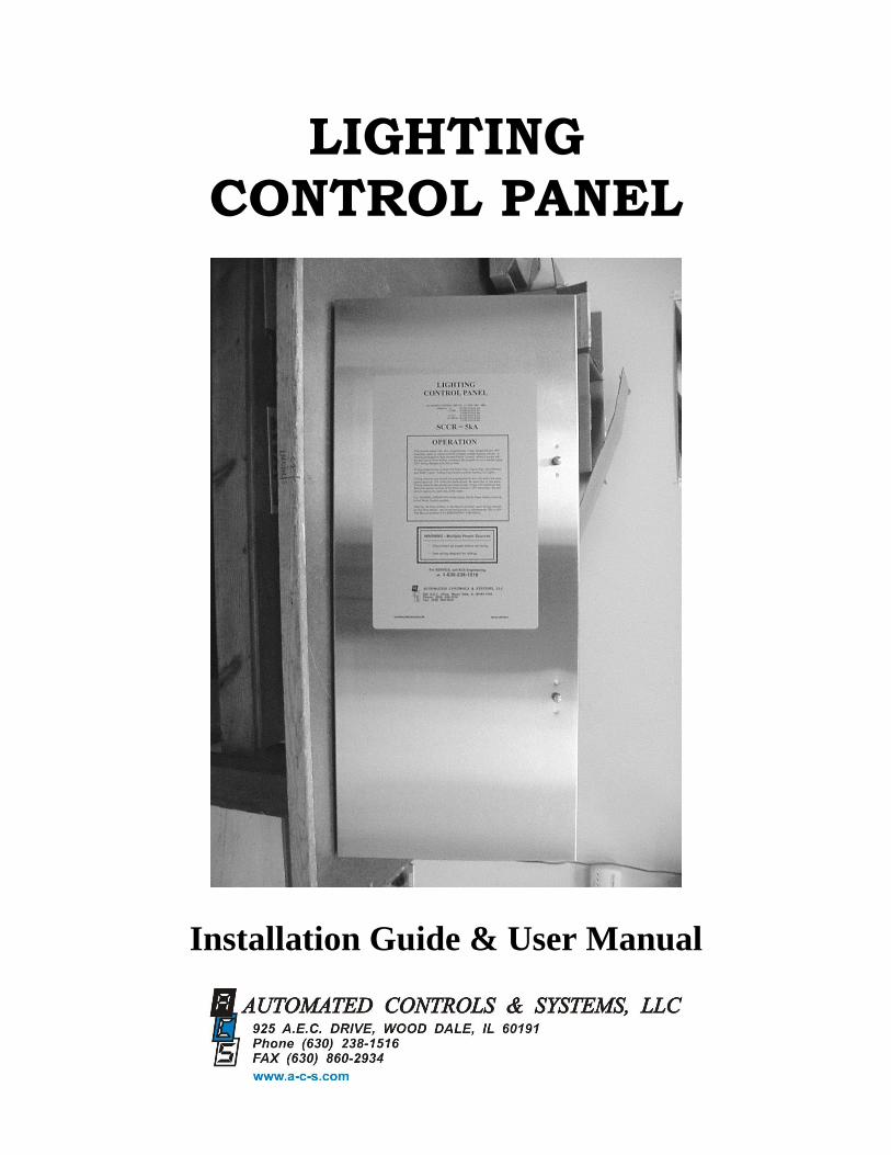
LIGHTING CONTROL PANEL
Installation Guide & User Manual

File Number 2-210, Rev. 3 J:\LCPANEL\MANUAL\LC PANEL… 2
THIS PAGE LEFT INTENTIONALLY BLANK
File Number 2-210, Rev. 3 J:\LCPANEL\MANUAL\LC PANEL… 3
WARRANTY STATEMENT
Automated Controls & Systems (ACS) warranties its equipment against defects in
workmanship and materials for a period of 90 days (labor) and 12 months (parts) from
date of installation.
Warranty applies only to original installation and to equipment subject to normal use and
service when such equipment is used in accordance with instructions furnished by ACS.
ASC’s liability under this warranty shall be limited to the replacement or repair of any
equipment or part which has been returned, prepaid to the factory, and which has been
determined, upon examination by ACS to be defective.
Under no circumstances shall ACS br liable to Buyer or any third party for any loss of
profits or other direct or indirect costs, expenses, losses or consequential damages arising
out of parts or components incorporated in ACS’s equipment but not supplied by ACS.
Operation of this unit on any voltage other than the specified operating voltage will void
warranty.
THIS WARRANTY IS IN LIEU OF ANY OTHER WARRANTY, EITHER
EXPRESSED OR IMPLLIED, AS TO DISCRIPTION, QUALITY,
MERCHANTABILITY, FITNESS FOR ANY PARTICULAR PURPOSE OR USE,
OR ANY OTHER MATTER.
File Number 2-210, Rev. 3 J:\LCPANEL\MANUAL\LC PANEL… 4
LIGHTING CONTROL PANEL User Manual
TABLE OF CONTENTS
WARRANTY 3
SPECIFICATIONS 5
PRINCIPLE OF OERATION 6
GENERAL DESCRIPTION 6
INSTALLATION & DETAILS 5
PROGRAMMABLE TIME SWITCH 5
LIGHTING SCHEDULE 6
SET TIME AND DAY 6
PROGRAMMING 7
REVIEW AND CHANGE OF PROGRAMS 8
MANUAL OVERRIDE 9
MANUAL DAYLIGHT SAVINGS TIME CHANGEOVER 10
PROGRAMMING CHART 11
PROGRAMMING EXAMPLE 11
TROUBLESHOOTING 11
PARTS ORDERING/RETURN INFORMATION 12
PARTS IDENTIFICATION 13
APPENDICES
LC PANEL 14
LC-HD PANEL 14
EXTENTION PANELS 14
GLOSSARY 14
File Number 2-210, Rev. 3 J:\LCPANEL\MANUAL\LC PANEL… 5
SPECIFICATIONS
ELECTRICAL
Controls: 3A 1PH 50/60 Hz
Power: Model LC
24A 120-240V – 28 Circuits
Model LC-HD
48A 120-240V – 4 Circuits
24A 120-240V – 28 Circuits
Model LC-EC
24A 120-240V – 32 Circuits
Model LC-HD-EC
48A 120-240V – 4 Circuits
24A 120-240V – 28 Circuits
ENVIRONMENTAL
Operating Temperature: 0-60 Degrees Centigrade
(32-140 Degrees Fahrenheit)
Humidity: 10-90% Relative Humidity
File Number 2-210, Rev. 3 J:\LCPANEL\MANUAL\LC PANEL… 6
PRINCIPLE OF OPERATION
The Lighting Control Panel is used to control the outside lights of the restaurant. It does this by turning
the parking lot lights ON or OFF as a group via a program on one channel of the Diehl Series 884.2k
timer. The other channel is used to control the outside signage as a group. The program is modified by
the condition of the outdoor ambient light via the Photo Control. If the program calls for the lights to be
ON and it is still light outside, the Photo Control inhibits the operation of the lights until it is dark.
Conversely, when the lights are ON and daybreak occurs, the lights will turn OFF via the operation of
the Photo Control. The BY-PASS SWITCH must be in the PHOTO CONTROL position for this to
happen. If it is in the MANUAL position, the lights are fully controlled by the Timer’s configuration.
GENERAL DESCRIPTION
ACS’s Lighting Control (LC) Panel is an industrial control panel with contactors and other control
elements including a user friendly microcomputer based two channel electronic time switch (timer). This
allows for the automatic control of the exterior lights of the restaurant.
Channel 1 includes Road Sign(s), Facia Signs, Roof Signs, Roof Beams and Soffit Lights.
Channel 2 is assigned to the Parking Lot Lights.
Timed parking lot light control gives employees leaving the building at night the security of being able
to walk to their vehicles in a lighted environment.
The LC Panel uses a roof mounted Photo Control which prevents the exterior lighting system from
turning ON while daylight is present. The Photo Control has a sliding cover which controls the amount
of light sensed by the photocell. The electronic time switch in conjunction with the roof mounted Photo
Control controls the ON/OFF cycling of the building’s exterior lights. To successfully turn any lighting
control channel ON, the Photo Control must sense a “dark” condition and the particular timed channel
must be in an ON state.
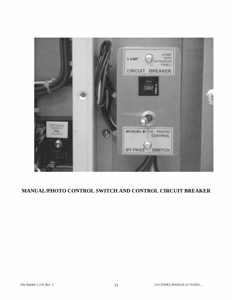
The LC Panel also provides a Photo Control bypass switch. This switch, labeled MANUAL/PHOTO
CONTROL, allows one to bypass the Photo Control feature of the lighting control system. When the
switch is in the MAN (manual) position, the Photo Control no longer has any effect on the exterior lights.
File Number 2-210, Rev. 3 J:\LCPANEL\MANUAL\LC PANEL… 7
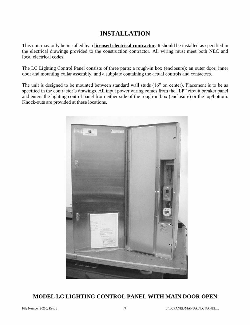
INSTALLATION
This unit may only be installed by a licensed electrical contractor. It should be installed as specified in
the electrical drawings provided to the construction contractor. All wiring must meet both NEC and
local electrical codes.
The LC Lighting Control Panel consists of three parts: a rough-in box (enclosure); an outer door, inner
door and mounting collar assembly; and a subplate containing the actual controls and contactors.
The unit is designed to be mounted between standard wall studs (16” on center). Placement is to be as
specified in the contractor’s drawings. All input power wiring comes from the “LP” circuit breaker panel
and enters the lighting control panel from either side of the rough-in box (enclosure) or the top/bottom.
Knock-outs are provided at these locations.
MODEL LC LIGHTING CONTROL PANEL WITH MAIN DOOR OPEN
File Number 2-210, Rev. 3 J:\LCPANEL\MANUAL\LC PANEL… 8
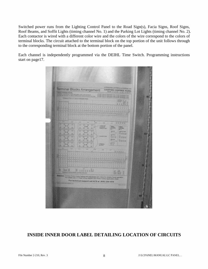
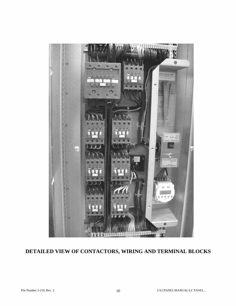
Switched power runs from the Lighting Control Panel to the Road Sign(s), Facia Signs, Roof Signs,
Roof Beams, and Soffit Lights (timing channel No. 1) and the Parking Lot Lights (timing channel No. 2).
Each contactor is wired with a different color wire and the colors of the wire correspond to the colors of
terminal blocks. The circuit attached to the terminal block on the top portion of the unit follows through
to the corresponding terminal block at the bottom portion of the panel.
Each channel is independently programmed via the DEIHL Time Switch. Programming instructions
start on page17.
INSIDE INNER DOOR LABEL DETAILING LOCATION OF CIRCUITS
File Number 2-210, Rev. 3 J:\LCPANEL\MANUAL\LC PANEL… 9
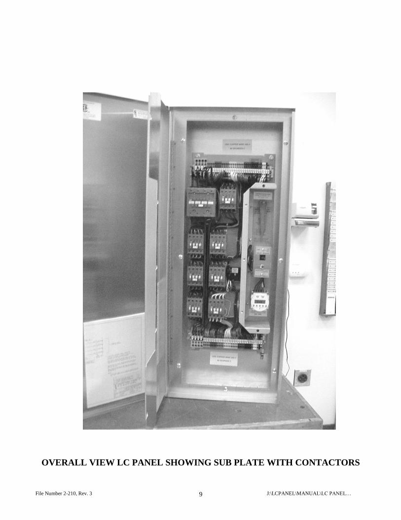
OVERALL VIEW LC PANEL SHOWING SUB PLATE WITH CONTACTORS
File Number 2-210, Rev. 3 J:\LCPANEL\MANUAL\LC PANEL… 10
DETAILED VIEW OF CONTACTORS, WIRING AND TERMINAL BLOCKS
File Number 2-210, Rev. 3 J:\LCPANEL\MANUAL\LC PANEL… 11
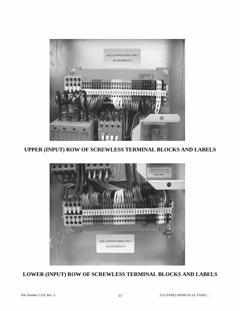
UPPER (INPUT) ROW OF SCREWLESS TERMINAL BLOCKS AND LABELS
LOWER (INPUT) ROW OF SCREWLESS TERMINAL BLOCKS AND LABELS
File Number 2-210, Rev. 3 J:\LCPANEL\MANUAL\LC PANEL… 12
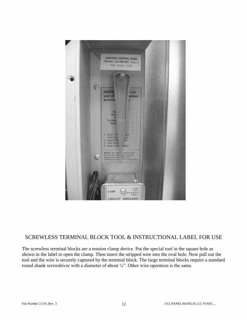
SCREWLESS TERMINAL BLOCK TOOL & INSTRUCTIONAL LABEL FOR USE
The screwless terminal blocks are a tension clamp device. Put the special tool in the square hole as
shown in the label to open the clamp. Then insert the stripped wire into the oval hole. Now pull out the
tool and the wire is securely captured by the terminal block. The large terminal blocks require a standard
round shank screwdriver with a diameter of about ¼”. Other wise operation is the same.
File Number 2-210, Rev. 3 J:\LCPANEL\MANUAL\LC PANEL… 13
MANUAL/PHOTO CONTROL SWITCH AND CONTROL CIRCUIT BREAKER
File Number 2-210, Rev. 3 J:\LCPANEL\MANUAL\LC PANEL… 14
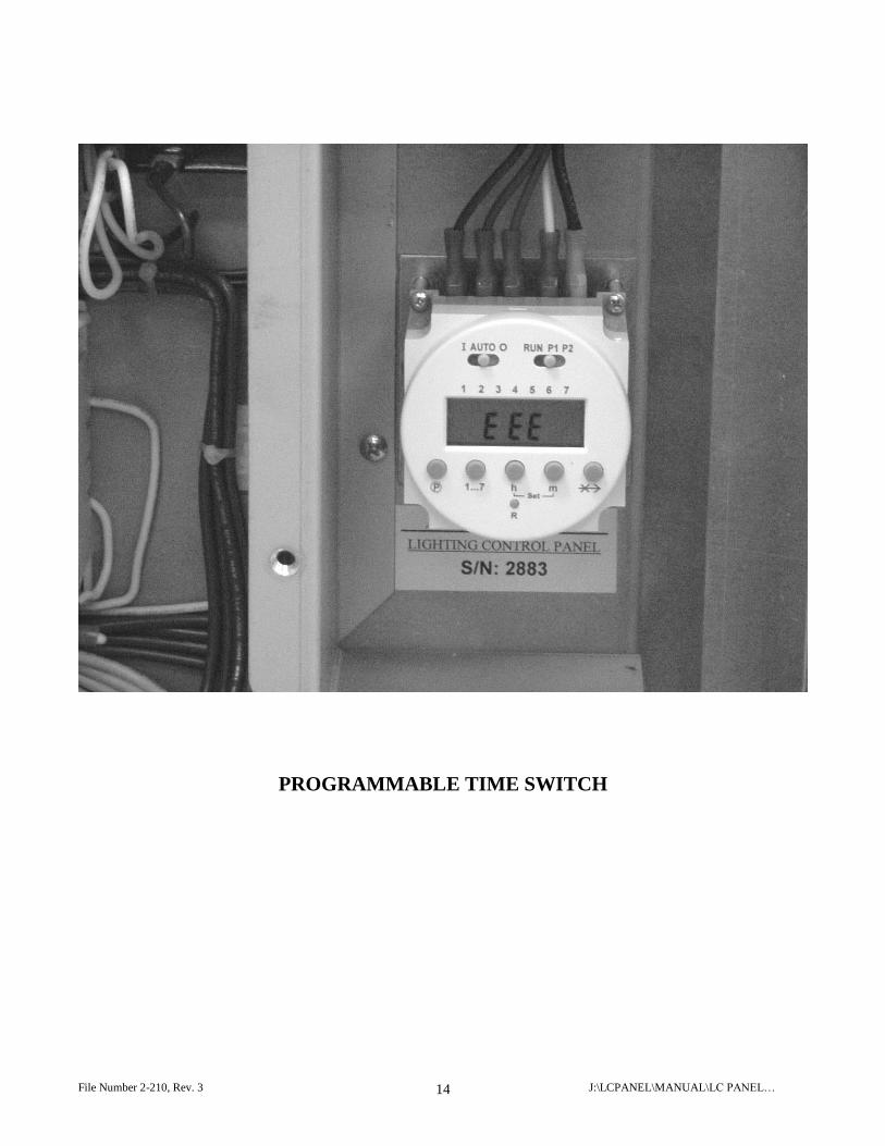
PROGRAMMABLE TIME SWITCH
File Number 2-210, Rev. 3 J:\LCPANEL\MANUAL\LC PANEL… 15
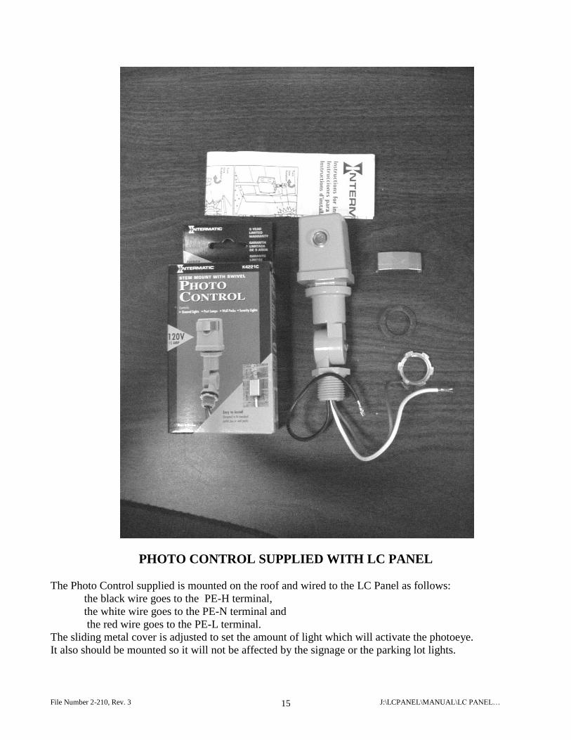
PHOTO CONTROL SUPPLIED WITH LC PANEL
The Photo Control supplied is mounted on the roof and wired to the LC Panel as follows:
the black wire goes to the PE-H terminal,
the white wire goes to the PE-N terminal and
the red wire goes to the PE-L terminal.
The sliding metal cover is adjusted to set the amount of light which will activate the photoeye.
It also should be mounted so it will not be affected by the signage or the parking lot lights.

File Number 2-210, Rev. 3 J:\LCPANEL\MANUAL\LC PANEL… 16
File Number 2-210, Rev. 3 J:\LCPANEL\MANUAL\LC PANEL… 17
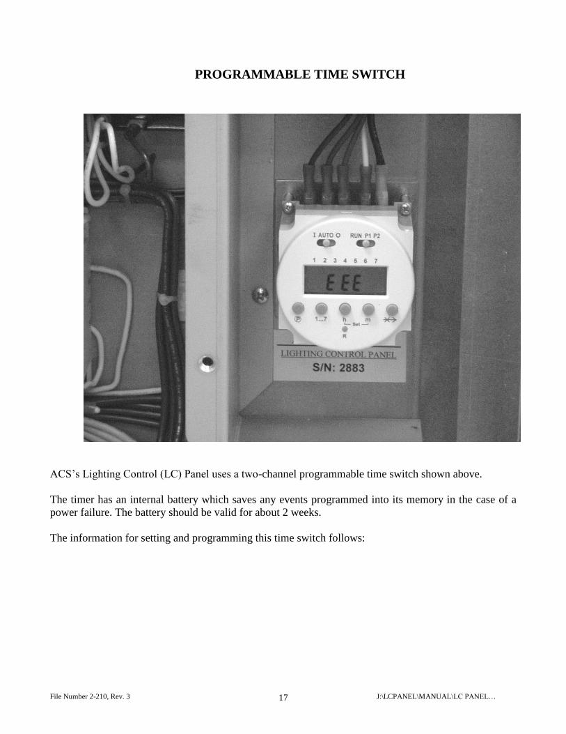
PROGRAMMABLE TIME SWITCH
ACS’s Lighting Control (LC) Panel uses a two-channel programmable time switch shown above.
The timer has an internal battery which saves any events programmed into its memory in the case of a
power failure. The battery should be valid for about 2 weeks.
The information for setting and programming this time switch follows:
File Number 2-210, Rev. 3 J:\LCPANEL\MANUAL\LC PANEL… 18
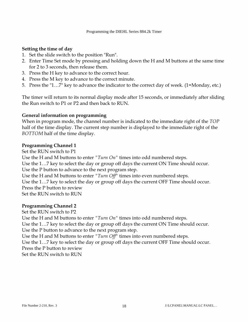
Programming the DIEHL Series 884.2k Timer
Setting the time of day 1. Set the slide switch to the position "Run". 2. Enter Time Set mode by pressing and holding down the H and M buttons at the same time
for 2 to 3 seconds, then release them. 3. Press the H key to advance to the correct hour. 4. Press the M key to advance to the correct minute. 5. Press the "1…7" key to advance the indicator to the correct day of week. (1=Monday, etc.) The timer will return to its normal display mode after 15 seconds, or immediately after sliding the Run switch to P1 or P2 and then back to RUN. General information on programming When in program mode, the channel number is indicated to the immediate right of the TOP half of the time display. The current step number is displayed to the immediate right of the BOTTOM half of the time display. Programming Channel 1 Set the RUN switch to P1 Use the H and M buttons to enter "Turn On" times into odd numbered steps. Use the 1…7 key to select the day or group off days the current ON Time should occur. Use the P button to advance to the next program step. Use the H and M buttons to enter "Turn Off" times into even numbered steps. Use the 1…7 key to select the day or group off days the current OFF Time should occur. Press the P button to review Set the RUN switch to RUN Programming Channel 2 Set the RUN switch to P2 Use the H and M buttons to enter "Turn On" times into odd numbered steps. Use the 1…7 key to select the day or group off days the current ON Time should occur. Use the P button to advance to the next program step. Use the H and M buttons to enter "Turn Off" times into even numbered steps. Use the 1…7 key to select the day or group off days the current OFF Time should occur. Press the P button to review Set the RUN switch to RUN

File Number 2-210, Rev. 3 J:\LCPANEL\MANUAL\LC PANEL… 19
To erase a program step; 1. Set the RUN switch to the program (P1 or P2) which contains the instruction to be erased. 2. Press the P button to advance to the program step to be erased.
3. Press and hold down the SKIP ( ) key, then press and hold down the P key at the same time, until the display shows 00:00.
4. The instruction has been erased.
File Number 2-210, Rev. 3 J:\LCPANEL\MANUAL\LC PANEL… 20
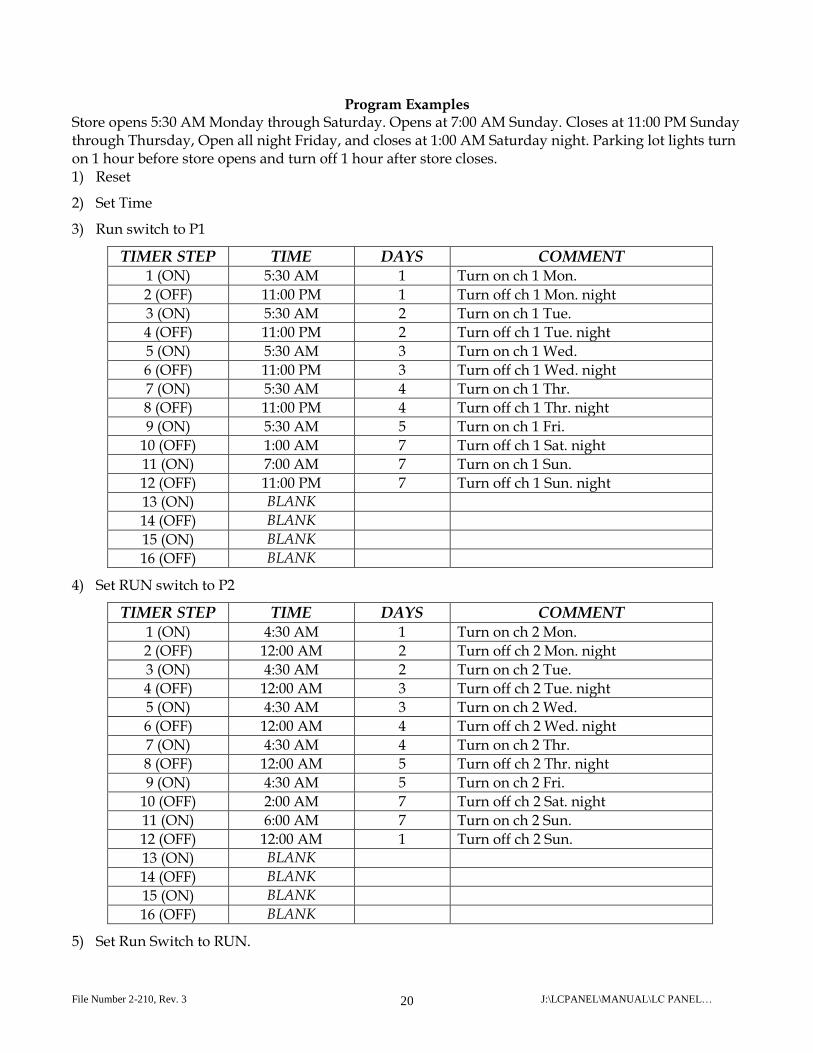
Program Examples Store opens 5:30 AM Monday through Saturday. Opens at 7:00 AM Sunday. Closes at 11:00 PM Sunday through Thursday, Open all night Friday, and closes at 1:00 AM Saturday night. Parking lot lights turn on 1 hour before store opens and turn off 1 hour after store closes. 1) Reset
2) Set Time
3) Run switch to P1
TIMER STEP TIME DAYS COMMENT 1 (ON) 5:30 AM 1 Turn on ch 1 Mon.
2 (OFF) 11:00 PM 1 Turn off ch 1 Mon. night
3 (ON) 5:30 AM 2 Turn on ch 1 Tue.
4 (OFF) 11:00 PM 2 Turn off ch 1 Tue. night
5 (ON) 5:30 AM 3 Turn on ch 1 Wed.
6 (OFF) 11:00 PM 3 Turn off ch 1 Wed. night
7 (ON) 5:30 AM 4 Turn on ch 1 Thr.
8 (OFF) 11:00 PM 4 Turn off ch 1 Thr. night
9 (ON) 5:30 AM 5 Turn on ch 1 Fri.
10 (OFF) 1:00 AM 7 Turn off ch 1 Sat. night
11 (ON) 7:00 AM 7 Turn on ch 1 Sun.
12 (OFF) 11:00 PM 7 Turn off ch 1 Sun. night
13 (ON) BLANK
14 (OFF) BLANK
15 (ON) BLANK
16 (OFF) BLANK
4) Set RUN switch to P2
TIMER STEP TIME DAYS COMMENT 1 (ON) 4:30 AM 1 Turn on ch 2 Mon.
2 (OFF) 12:00 AM 2 Turn off ch 2 Mon. night
3 (ON) 4:30 AM 2 Turn on ch 2 Tue.
4 (OFF) 12:00 AM 3 Turn off ch 2 Tue. night
5 (ON) 4:30 AM 3 Turn on ch 2 Wed.
6 (OFF) 12:00 AM 4 Turn off ch 2 Wed. night
7 (ON) 4:30 AM 4 Turn on ch 2 Thr.
8 (OFF) 12:00 AM 5 Turn off ch 2 Thr. night
9 (ON) 4:30 AM 5 Turn on ch 2 Fri.
10 (OFF) 2:00 AM 7 Turn off ch 2 Sat. night
11 (ON) 6:00 AM 7 Turn on ch 2 Sun.
12 (OFF) 12:00 AM 1 Turn off ch 2 Sun.
13 (ON) BLANK
14 (OFF) BLANK
15 (ON) BLANK
16 (OFF) BLANK
5) Set Run Switch to RUN.
File Number 2-210, Rev. 3 J:\LCPANEL\MANUAL\LC PANEL… 21
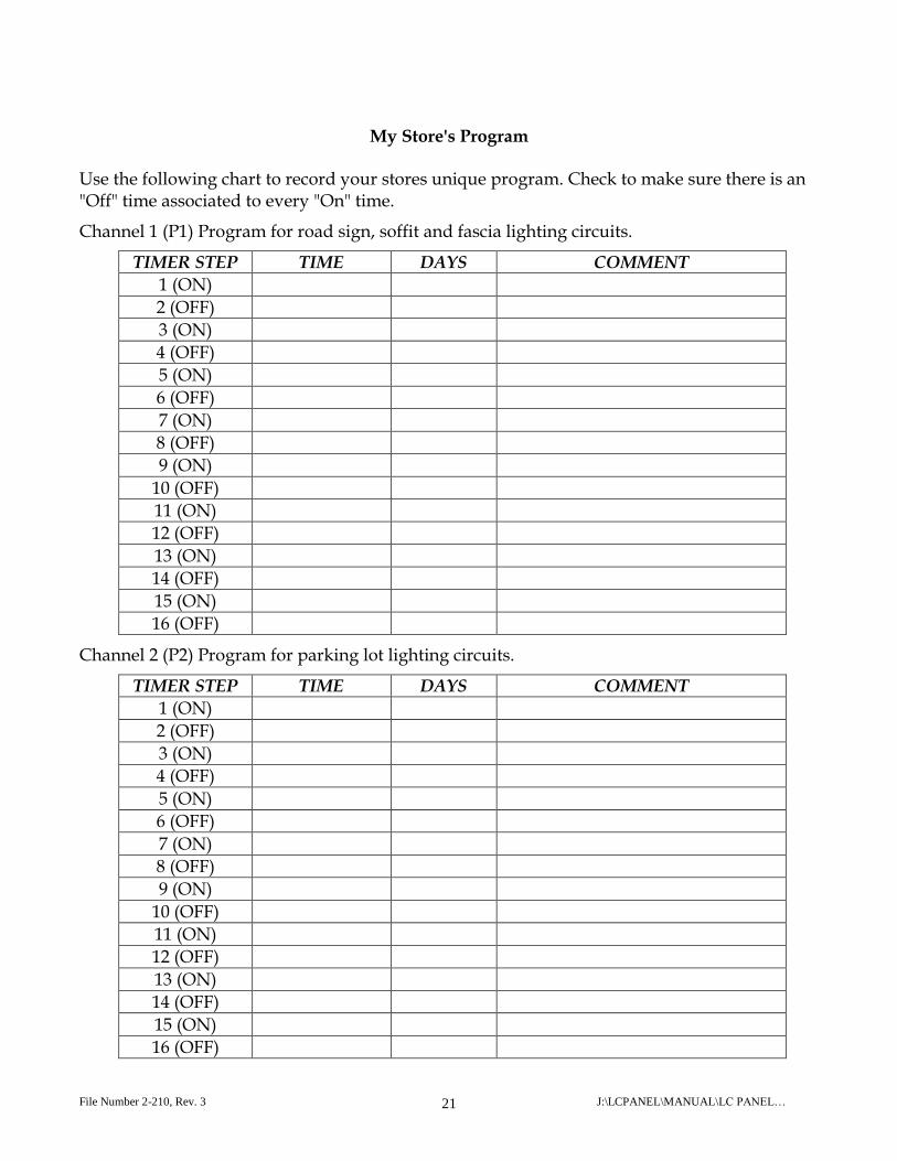
My Store's Program
Use the following chart to record your stores unique program. Check to make sure there is an "Off" time associated to every "On" time.
Channel 1 (P1) Program for road sign, soffit and fascia lighting circuits.
TIMER STEP TIME DAYS COMMENT
1 (ON)
2 (OFF)
3 (ON)
4 (OFF)
5 (ON)
6 (OFF)
7 (ON)
8 (OFF)
9 (ON)
10 (OFF)
11 (ON)
12 (OFF)
13 (ON)
14 (OFF)
15 (ON)
16 (OFF)
Channel 2 (P2) Program for parking lot lighting circuits.
TIMER STEP TIME DAYS COMMENT
1 (ON)
2 (OFF)
3 (ON)
4 (OFF)
5 (ON)
6 (OFF)
7 (ON)
8 (OFF)
9 (ON)
10 (OFF)
11 (ON)
12 (OFF)
13 (ON)
14 (OFF)
15 (ON)
16 (OFF)