Embed Size (px)
Citation preview
LIGHTING CONTROL PANELS INSTALLATION INSTRUCTIONS
9601 Dessau Road, Building One | Austin, TX 78754 Toll Free: 888-698-3242 | Fax: 512-450-1215 | www.hubbell-automation.com
INSTALLATION OVERVIEW
The installation instructions contained in this document are provided as a guide for proper and reliable installation. The mounting location should be selected and prepared based on the application. All electrical wiring and mounting hardware (i.e. electrical mounting box, conduit, etc.) should be prepared with consideration of the requirements outlined in the wiring and mounting diagrams below.
These instructions include information as follows:
DescriptionProduct ConfigurationsEnclosure Mounting Installing Individual Relay CardsConnecting Panel PowerConnecting Lighting LoadsConnecting Low Voltage InputsOperating the PanelTroubleshootingPanel SpecificationsPanel Load Schedule Form
PRECAUTIONS
• READ AND FOLLOW ALL SAFETY INSTRUCTIONS.• CAUTION - RISK OF ELECTRICAL SHOCK. To prevent electrical shock, turn off power at the circuit breaker before
installing or servicing unit. Never wire energized electrical components.• NOTICE: For installation by a licensed electrician in accordance with National and/or local Electrical Codes and the
following instructions.• CAUTION: USE COPPER CONDUCTOR ONLY.• Be sure to read and understand all instructions before installing or servicing unit• For Indoor use only. Do not use outdoors.• Do not mount near gas or electric heaters.• Disconnect switch or a circuit breaker must be provided and marked as the disconnecting device.• The use of accessory equipment not recommended by the manufacturer may cause an unsafe condition.• Confirm that device ratings are suitable for application prior to installation.• No user serviceable parts contained inside unit. Refer all service related questions to the factory. • All servicing shall be performed by qualified service personnel.• Equipment should be mounted in locations and at heights where it will not readily be subjected to tampering by
unauthorized personnel.• Use only approved materials and components (i.e. twist on connectors, electrical box, etc.) as appropriate for
installation.• NOTICE: Do not install if product appears to be damaged.• If the equipment is used in a manner not specified by the manufacturer, the protection provided by the equipment may
be impaired.• Do not use this equipment for other than intended use.
SAVE THESE INSTRUCTIONS!
™
3452B 3.17.2016
Page 2
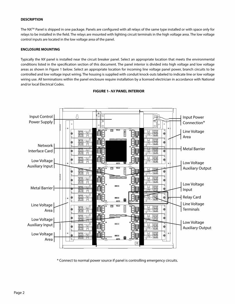
FIGURE 1- NX PANEL INTERIOR
DESCRIPTION
The NXTM Panel is shipped in one package. Panels are configured with all relays of the same type installed or with space only for relays to be installed in the field. The relays are mounted with lighting circuit terminals in the high voltage area. The low voltage control inputs are located in the low voltage area of the panel.
ENCLOSURE MOUNTING
Typically the NX panel is installed near the circuit breaker panel. Select an appropriate location that meets the environmental conditions listed in the specification section of this document. The panel interior is divided into high voltage and low voltage areas as shown in Figure 1 below. Select an appropriate location for incoming line voltage panel power, branch circuits to be controlled and low voltage input wiring. The housing is supplied with conduit knock-outs labeled to indicate line or low voltage wiring use. All terminations within the panel enclosure require installation by a licensed electrician in accordance with National and/or local Electrical Codes.
Low VoltageAuxiliary Output
Low VoltageInput
Relay Card
Line Voltage Terminals
Low VoltageAuxiliary Output
Line VoltageArea
Metal Barrier
Input ControlPower Supply
Low VoltageAuxiliary Input
Metal Barrier
Low VoltageAuxiliary Input
NetworkInterface Card
Line VoltageArea
Low VoltageArea
Input PowerConnection*
* Connect to normal power source if panel is controlling emergency circuits.
Page 3
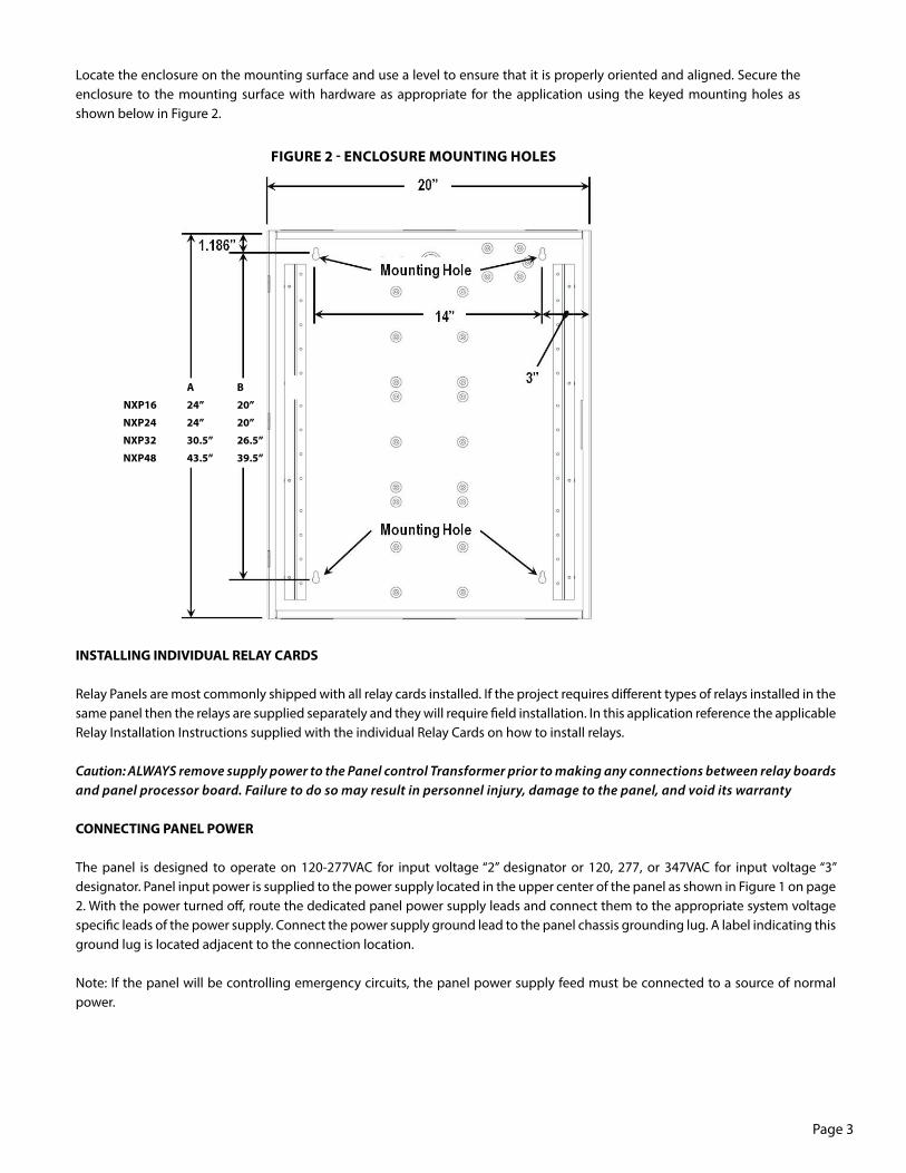
A B
NXP16 24” 20”
NXP24 24” 20”
NXP32 30.5” 26.5”
NXP48 43.5” 39.5”
FIGURE 2 - ENCLOSURE MOUNTING HOLES
Locate the enclosure on the mounting surface and use a level to ensure that it is properly oriented and aligned. Secure the enclosure to the mounting surface with hardware as appropriate for the application using the keyed mounting holes as shown below in Figure 2.
INSTALLING INDIVIDUAL RELAY CARDS
Relay Panels are most commonly shipped with all relay cards installed. If the project requires different types of relays installed in the same panel then the relays are supplied separately and they will require field installation. In this application reference the applicable Relay Installation Instructions supplied with the individual Relay Cards on how to install relays.
Caution: ALWAYS remove supply power to the Panel control Transformer prior to making any connections between relay boards and panel processor board. Failure to do so may result in personnel injury, damage to the panel, and void its warranty
CONNECTING PANEL POWER
The panel is designed to operate on 120-277VAC for input voltage “2” designator or 120, 277, or 347VAC for input voltage “3” designator. Panel input power is supplied to the power supply located in the upper center of the panel as shown in Figure 1 on page 2. With the power turned off, route the dedicated panel power supply leads and connect them to the appropriate system voltage specific leads of the power supply. Connect the power supply ground lead to the panel chassis grounding lug. A label indicating this ground lug is located adjacent to the connection location.
Note: If the panel will be controlling emergency circuits, the panel power supply feed must be connected to a source of normal power.
Page 4
CONNECTING LIGHTING LOADS
With the power turned off, route the lighting system line and load leads through the high voltage area of the panel shown in Figure 1 on page 2. Connect line and load leads for each lighting load to the output terminals of the appropriate relay as delineated in the project plans and/or Panel Load Schedule.
Notice: As a general rule, the panel is shipped with relays installed and electrically connected at their input control side. If, however, relays must be installed, reference the applicable Relay Installation Instructions supplied with the individual Relay Cards on how to install relays.
Caution: Prior to making any connections to the relay outputs, verify that none of the loads are shorted. Failure to do so may result in personnel injury, damage to the panel, and void its warranty
USING THE NXP PANEL FOR CONTROL OF EMERGENCY LIGHTINGNXP series panels equipped with NXR-3LEM single pole relay modules are suitable for control of emergency lighting circuits. The NXR-3LEM relays will automatically go to the closed (on) position upon loss of normal power that is feeding the panel’s power supply. Upon restoration of normal power to the panel’s power supply, the relays will revert to the appropriate on or off state as determined by the panel logic.
CONNECTING LOW VOLTAGE INPUTS
Bring the low voltage wiring for the contact inputs in through the knockouts in the low voltage wiring area where indicated in Figure 1 on page 2. Inputs are software configurable through programming to support momentary switches, maintained switches (latching), motion sensors, or photocells. Each Relay Card includes one low voltage input. The panel mother board includes 2 Auxiliary Inputs. These inputs may be connected prior to programming. Inputs may be connected to any terminal location regardless of final control programming. Connect contact closure input devices to the input terminals using 18 AWG wire.
Notice: Use the Panel Load Schedule Form supplied in the clear plastic pocket inside the Panel Door to record the low voltage input types while making connections.
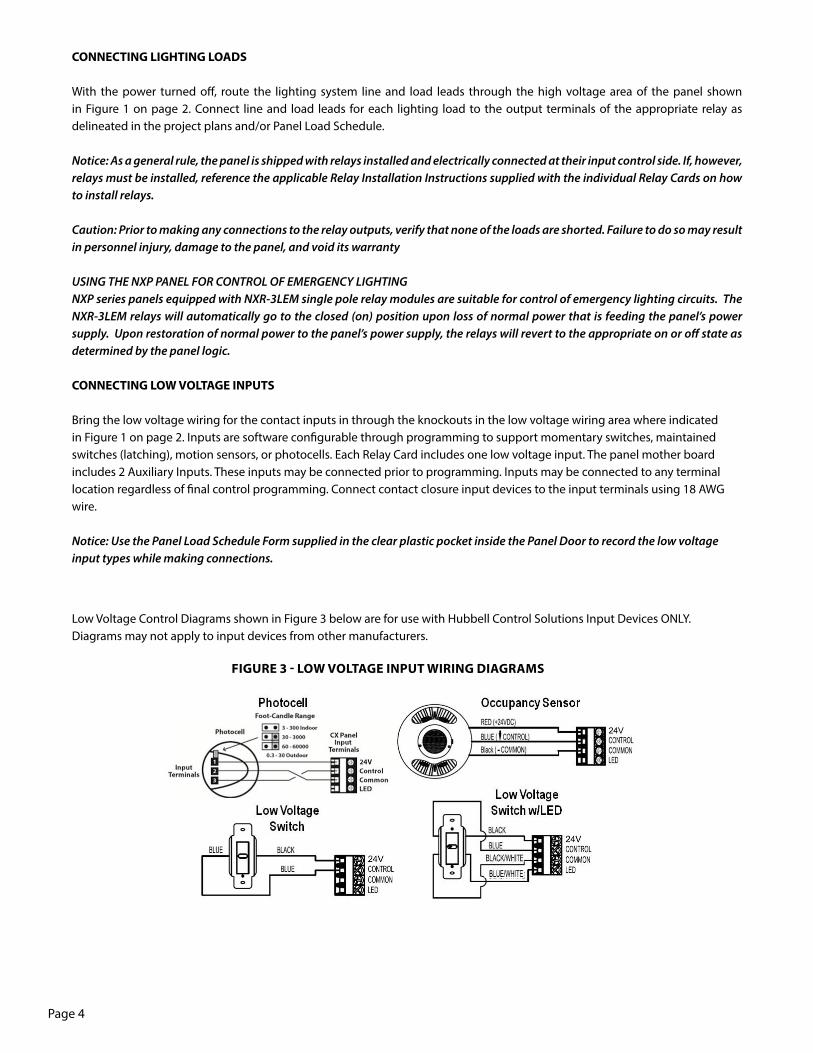
FIGURE 3 - LOW VOLTAGE INPUT WIRING DIAGRAMS
Low Voltage Control Diagrams shown in Figure 3 below are for use with Hubbell Control Solutions Input Devices ONLY. Diagrams may not apply to input devices from other manufacturers.
Page 5
CONNECTING THE HUBBNET™ NETWORK
The NX™ Lighting Control Panel is designed to operate as part of a NX Networked Lighting Control system. Once programmed, the panel will operate independently from a network connection. No software installation is required. However, a network connection to the Area Controller is required for programming the panel. The programming interface is served from the Area Controller and is accessible via a standard web browser on any compatible PC or computer.
The NX HubbNet network is Ethernet compatible with the exception that the Cat5 HubbNet cable carries 24 VDC as an integral power source for certain NX peripheral devices. CAUTION: never plug a HubbNet powered network cable directly into a PC or other Ethernet device. HCS offers accessory devices that allow HubbNet to be converted to standard Ethernet or Ethernet to be converted back to HubbNet. Contact HCS Technical Services for additional information.
The network interface in the panel is configured to provide an IN and OUT connection point for the HubbNet network. This allows a single daisy chain connection of the panels minimizing the amount of Cat5 wire required to connect the Area Controller to the network of panels. See Figure 4
1. Connect the Cat5 cable from the Area Controller into the Non-Powered RJ-45 connector on the network interface board of the first panel2. Connect the Powered RJ-45 connector on the network interface board of the first panel to the Non-Powered RJ-45 connector in the next panel3. Continue to run the network until all panels are connected. IMPORTANT: rout the network so that there is no more than 100 meters (330 feet) of Cat5 wire between any two panels. NOTE: Consult the factory if the installation requires a longer wire run than 100 meters between panels.
4. With the Area Controller and the panels powered, check to be sure there is a green LED (link light) adjacent to each RJ-45 connector. If the link light is not lit, confirm the installation of the RJ-5 connectors on the cables using a proper testing device.
CAUTION: Never attempt to splice Cat5 cable. Use only proper industry accepted means to extend or join Cat5 Ethernet network cable runs.
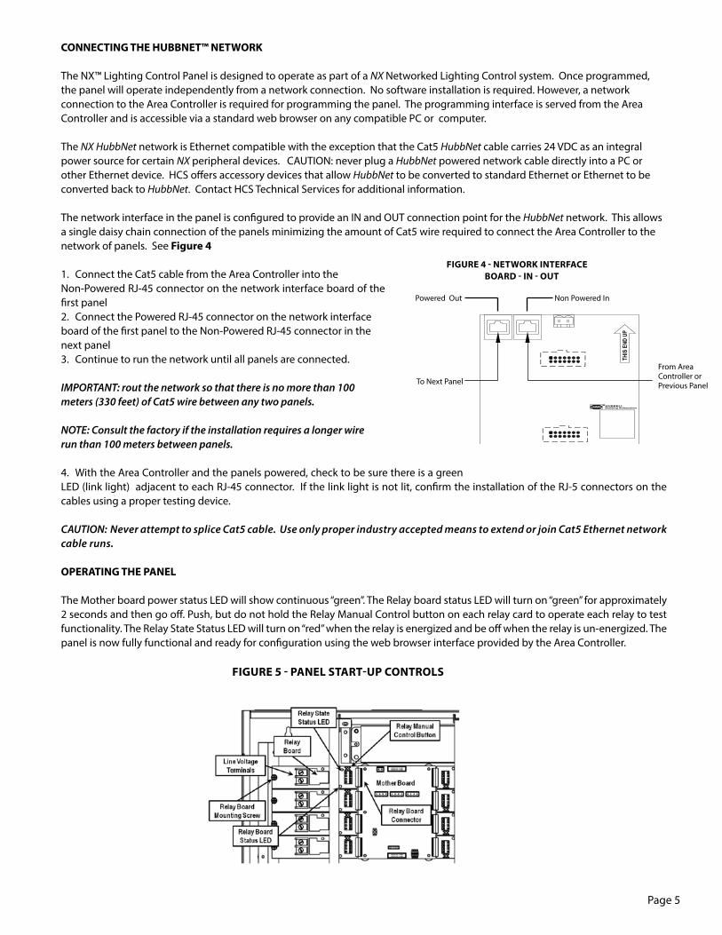
OPERATING THE PANEL
The Mother board power status LED will show continuous “green”. The Relay board status LED will turn on “green” for approximately 2 seconds and then go off. Push, but do not hold the Relay Manual Control button on each relay card to operate each relay to test functionality. The Relay State Status LED will turn on “red” when the relay is energized and be off when the relay is un-energized. The panel is now fully functional and ready for configuration using the web browser interface provided by the Area Controller.
FIGURE 5 - PANEL START-UP CONTROLS
FIGURE 4 - NETWORK INTERFACE BOARD - IN - OUT
From Area Controller or Previous PanelTo Next Panel
Powered Out Non Powered In
Page 6
TROUBLESHOOTING
A blinking “green” Relay board status LED indicates that communication has not been properly established for this card. Contact Hubbell Control Solutions Technical Service at (800) 888-8006 for assistance and replacement as required.
NX™ PANEL SPECIFICATIONS
Panel Input Power Requirements:• Input Voltage “2” designator – 100VA, 120-277VAC universal• Input Voltage “3” designator – 100VA, 347VAC
Overall Dimensions:• 14.5”W x 18.25”H x 4”D - NXP-08 Capacity• 20”W x 24”H x 4”D - NXP-16 & NXP-24 Capacity• 20”W x 30.5”H x 4”D - NXP-32 Capacity• 20”W x 43.5”H x 4”D - NXP-48 Capacity
Relay Load Ratings:• NXR-3LEM and NXR-3L• 120/277VAC - 16 Amps electronic ballast/LED driver, 30 Amps HID and fluorescent ballast, 20 Amps tungsten, 1HP motor (120 VAC only)• 347VAC - 16 Amps. electronic ballast/LED driver, 20 Amps. HID and fluorescent ballast• NXRTN – 208/240/480VAC, Electrically Held, N/O, 20Amps, HID, Ballast, 2HP• NXRTC – 208/240/480VAC, Electrically Held, N/C, 20Amps, HID, Ballast, 2HP• NXR2N – 120/277VAC, Electrically Held, N/O, 20Amps, HID and Fluorescent Ballast 15Amps, Fluorescent • Electronic Ballast 16 Amps, Tungsten (120V only) 15 Amps, 3/4HP at 120V and 277V,
Low Voltage Inputs:• Low Voltage Switches – 2 or 3 wire momentary or maintained style, with or without LED indication. LED indication support is LED – “ON” when switch is active and LED – “OFF” when switch is inactive. Green “ON” with Red “OFF” indication is not supported.• Motion Sensor Input – Three wire 24 VDC• Photocell – Three wire 24VDC power, 0-10V DC control input.
Low Voltage Output Relay Contacts:• Two per each motherboard – Dry Contact Output Form-C (NO/NC), 24V AC/DC, 50mA
Operating Environment:• Indoor Use Only; 0 to 50°C; Relative Humidity: 0 – 90% non-condensing.
PANEL LOAD SCHEDULE FORM
A Panel Load Schedule Form is supplied in the clear plastic pocket inside the Panel Door to record the lighting circuit relay assignments while connecting the relays. Low voltage input types and assignments should also be recorded on the form.
72-00564 Rev. B