Embed Size (px)
Citation preview
R
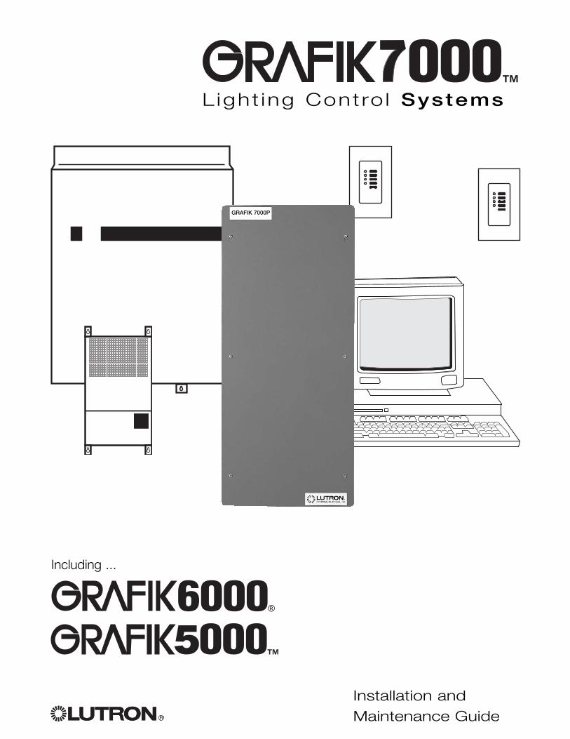
Installation andMaintenance Guide
L ight ing Contro l Systems
�
Including ...
GRAFIK 7000P
R2 Installation of GRAFIK5000 / GRAFIK6000 / GRAFIK7000 System
System Overview
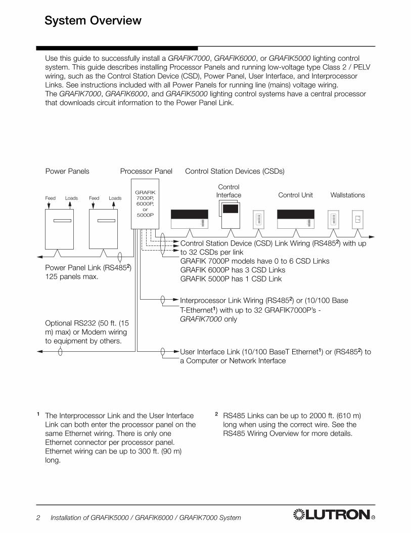
Power Panel Link (RS4852)125 panels max.
Control Station Device (CSD) Link Wiring (RS4852) with upto 32 CSDs per linkGRAFIK 7000P models have 0 to 6 CSD LinksGRAFIK 6000P has 3 CSD LinksGRAFIK 5000P has 1 CSD Link
Power Panels
Interprocessor Link Wiring (RS4852) or (10/100 Base T-Ethernet1) with up to 32 GRAFIK7000P’s - GRAFIK7000 only
User Interface Link (10/100 BaseT Ethernet1) or (RS4852) toa Computer or Network Interface
Optional RS232 (50 ft. (15m) max) or Modem wiringto equipment by others.
Control Station Devices (CSDs)
GRAFIK7000P,6000P,
or5000P
Feed
Use this guide to successfully install a GRAFIK7000, GRAFIK6000, or GRAFIK5000 lighting controlsystem. This guide describes installing Processor Panels and running low-voltage type Class 2 / PELVwiring, such as the Control Station Device (CSD), Power Panel, User Interface, and InterprocessorLinks. See instructions included with all Power Panels for running line (mains) voltage wiring.The GRAFIK7000, GRAFIK6000, and GRAFIK5000 lighting control systems have a central processorthat downloads circuit information to the Power Panel Link.
1 The Interprocessor Link and the User InterfaceLink can both enter the processor panel on thesame Ethernet wiring. There is only oneEthernet connector per processor panel.Ethernet wiring can be up to 300 ft. (90 m)long.
Processor Panel
Control UnitControl
Interface WallstationsFeed LoadsLoads
2 RS485 Links can be up to 2000 ft. (610 m)long when using the correct wire. See theRS485 Wiring Overview for more details.
R Installation of GRAFIK5000 / GRAFIK6000 / GRAFIK7000 System 3
Step-by-Step Instructions
Table of Contents
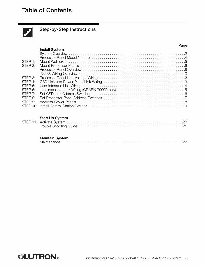
PageInstall SystemSystem Overview . . . . . . . . . . . . . . . . . . . . . . . . . . . . . . . . . . . . . . . . . . . . . . . . . . . . . . . . .2Processor Panel Model Numbers . . . . . . . . . . . . . . . . . . . . . . . . . . . . . . . . . . . . . . . . . . . . .4
STEP 1: Mount Wallboxes . . . . . . . . . . . . . . . . . . . . . . . . . . . . . . . . . . . . . . . . . . . . . . . . . . . . . . . . .5STEP 2: Mount Processor Panels . . . . . . . . . . . . . . . . . . . . . . . . . . . . . . . . . . . . . . . . . . . . . . . . . . .6
Processor Panel Overview . . . . . . . . . . . . . . . . . . . . . . . . . . . . . . . . . . . . . . . . . . . . . . . . . .8RS485 Wiring Overview . . . . . . . . . . . . . . . . . . . . . . . . . . . . . . . . . . . . . . . . . . . . . . . . . . .10
STEP 3: Processor Panel Line-Voltage Wiring . . . . . . . . . . . . . . . . . . . . . . . . . . . . . . . . . . . . . . . . .12STEP 4: CSD Link and Power Panel Link Wiring . . . . . . . . . . . . . . . . . . . . . . . . . . . . . . . . . . . . . . .13STEP 5: User Interface Link Wiring . . . . . . . . . . . . . . . . . . . . . . . . . . . . . . . . . . . . . . . . . . . . . . . . .14STEP 6: Interprocessor Link Wiring (GRAFIK 7000P only) . . . . . . . . . . . . . . . . . . . . . . . . . . . . . . . .15STEP 7: Set CSD Link Address Switches . . . . . . . . . . . . . . . . . . . . . . . . . . . . . . . . . . . . . . . . . . . .16STEP 8: Set Processor Panel Address Switches . . . . . . . . . . . . . . . . . . . . . . . . . . . . . . . . . . . . . . .17STEP 9: Address Power Panels . . . . . . . . . . . . . . . . . . . . . . . . . . . . . . . . . . . . . . . . . . . . . . . . . . . .18STEP 10: Install Control Station Devices . . . . . . . . . . . . . . . . . . . . . . . . . . . . . . . . . . . . . . . . . . . . . .19
Start Up SystemSTEP 11: Activate System . . . . . . . . . . . . . . . . . . . . . . . . . . . . . . . . . . . . . . . . . . . . . . . . . . . . . . . . .20
Trouble Shooting Guide . . . . . . . . . . . . . . . . . . . . . . . . . . . . . . . . . . . . . . . . . . . . . . . . . . .21
Maintain SystemMaintenance . . . . . . . . . . . . . . . . . . . . . . . . . . . . . . . . . . . . . . . . . . . . . . . . . . . . . . . . . . .22
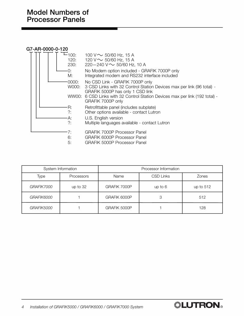
Name
GRAFIK 7000P
GRAFIK 6000P
GRAFIK 5000P
R4 Installation of GRAFIK5000 / GRAFIK6000 / GRAFIK7000 System
100: 100 V 50/60 Hz, 15 A120: 120 V 50/60 Hz, 15 A230: 220—240 V 50/60 Hz, 10 A
G7-AR-0000-0-120
0: No Modem option included - GRAFIK 7000P onlyM: Integrated modem and RS232 interface included0000: No CSD Link - GRAFIK 7000P onlyW000: 3 CSD Links with 32 Control Station Devices max per link (96 total) -
GRAFIK 5000P has only 1 CSD linkWW00: 6 CSD Links with 32 Control Station Devices max per link (192 total) -
GRAFIK 7000P onlyR: Retrofittable panel (includes subplate)?: Other options available - contact LutronA: U.S. English version?: Multiple languages available - contact Lutron
7: GRAFIK 7000P Processor Panel6: GRAFIK 6000P Processor Panel5: GRAFIK 5000P Processor Panel
Model Numbers ofProcessor Panels
Type
GRAFIK7000
GRAFIK6000
GRAFIK5000
CSD Links
up to 6
3
1
Processors
up to 32
1
1
Zones
up to 512
512
128
System Information Processor Information
Step 1
R Installation of GRAFIK5000 / GRAFIK6000 / GRAFIK7000 System 5
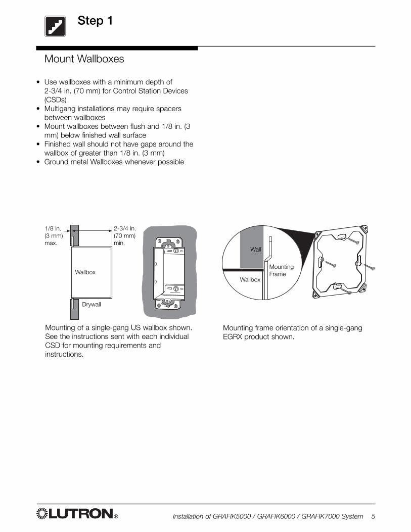
• Use wallboxes with a minimum depth of 2-3/4 in. (70 mm) for Control Station Devices(CSDs)
• Multigang installations may require spacersbetween wallboxes
• Mount wallboxes between flush and 1/8 in. (3mm) below finished wall surface
• Finished wall should not have gaps around thewallbox of greater than 1/8 in. (3 mm)
• Ground metal Wallboxes whenever possible
Drywall
Wallbox
2-3/4 in.(70 mm)min.
1/8 in.(3 mm)max.
Mount Wallboxes
Mounting of a single-gang US wallbox shown.See the instructions sent with each individualCSD for mounting requirements andinstructions.
Mounting frame orientation of a single-gangEGRX product shown.
MountingFrame
Wall
Wallbox
STEP 2
R6 Installation of GRAFIK5000 / GRAFIK6000 / GRAFIK7000 System
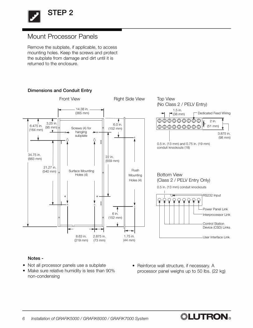
Mount Processor Panels
Remove the subplate, if applicable, to accessmounting holes. Keep the screws and protectthe subplate from damage and dirt until it isreturned to the enclosure.
14.38 in.(365 mm)
3.875 in.(98 mm)
2 in.
(51 mm)
RS232 Input
Front View Right Side View
Power Panel Link
1.5 in.(38 mm)
6.475 in.(164 mm)
8.63 in.(219 mm)
2.875 in.(73 mm)
0.5 in. (13 mm) conduit knockouts
Surface MountingHoles (4)
Dedicated Feed Wiring
Control StationDevice (CSD) Links
User Interface Link
Bottom View (Class 2 / PELV Entry Only)
Flush
Mounting
Holes (4)
34.75 in.(883 mm)
Interprocessor Link
Screws (4) forhangingsubplate
21.27 in.(540 mm)
Top View(No Class 2 / PELV Entry)
3.25 in.(95 mm)
6.0 in.(152 mm)
6 in.(152 mm)
1.75 in.(44 mm)
22 in.(559 mm)
0.5 in. (13 mm) and 0.75 in. (19 mm) conduit knockouts (18)
Dimensions and Conduit Entry
Notes -
• Not all processor panels use a subplate• Make sure relative humidity is less than 90%
non-condensing
• Reinforce wall structure, if necessary. Aprocessor panel weighs up to 50 lbs. (22 kg)
STEP 2 (Continued)
R Installation of GRAFIK5000 / GRAFIK6000 / GRAFIK7000 System 7
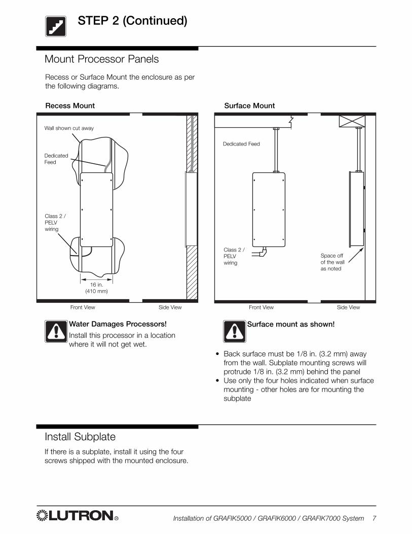
Mount Processor Panels
Water Damages Processors!
Install this processor in a locationwhere it will not get wet.
Recess or Surface Mount the enclosure as perthe following diagrams.
Surface mount as shown!
• Back surface must be 1/8 in. (3.2 mm) awayfrom the wall. Subplate mounting screws willprotrude 1/8 in. (3.2 mm) behind the panel
• Use only the four holes indicated when surfacemounting - other holes are for mounting thesubplate
Recess Mount Surface Mount
DedicatedFeed
Space offof the wallas noted
Side ViewFront View Side ViewFront View
Wall shown cut away
16 in.(410 mm)
Class 2 /PELVwiring
Class 2 /PELVwiring
Dedicated Feed
Install SubplateIf there is a subplate, install it using the fourscrews shipped with the mounted enclosure.
R8 Installation of GRAFIK5000 / GRAFIK6000 / GRAFIK7000 System
Processor Panel Overview
��
�
���
�
��
� �
��
�
�
�
�
�
�
���
� � � �
�� ������
��
�
���
�
��
� �
��
�
�
�
�
�
�
���
� � � �
�� �������
��
�
���
�
��
� �
��
�
�
�
�
�
�
���
� � � �
�� �������
��
�
���
�
��
� �
��
�
�
�
�
�
�
���
� � � �
�� �������
��
�
���
�
��
� �
��
�
�
�
�
�
�
���
� � � �
�� �������
��
�
���
�
��
� �
��
�
�
�
�
�
�
���
� � � �
�� �������
��
��
�
���
�
�
�
�
�
���
� � � �
�������
��
��
�
��
�
�
�
�
�
�
���
� � � �
�������� ���� ������ ��!
��
��
�
��
�
�
�
�
�
�
���
� � � �
�������
��
�
��
��
�
��
�
�
�
�
�
�
���
� � � �
�������
��"�����#$%
&'(((�� �
� � � � ) * '
�
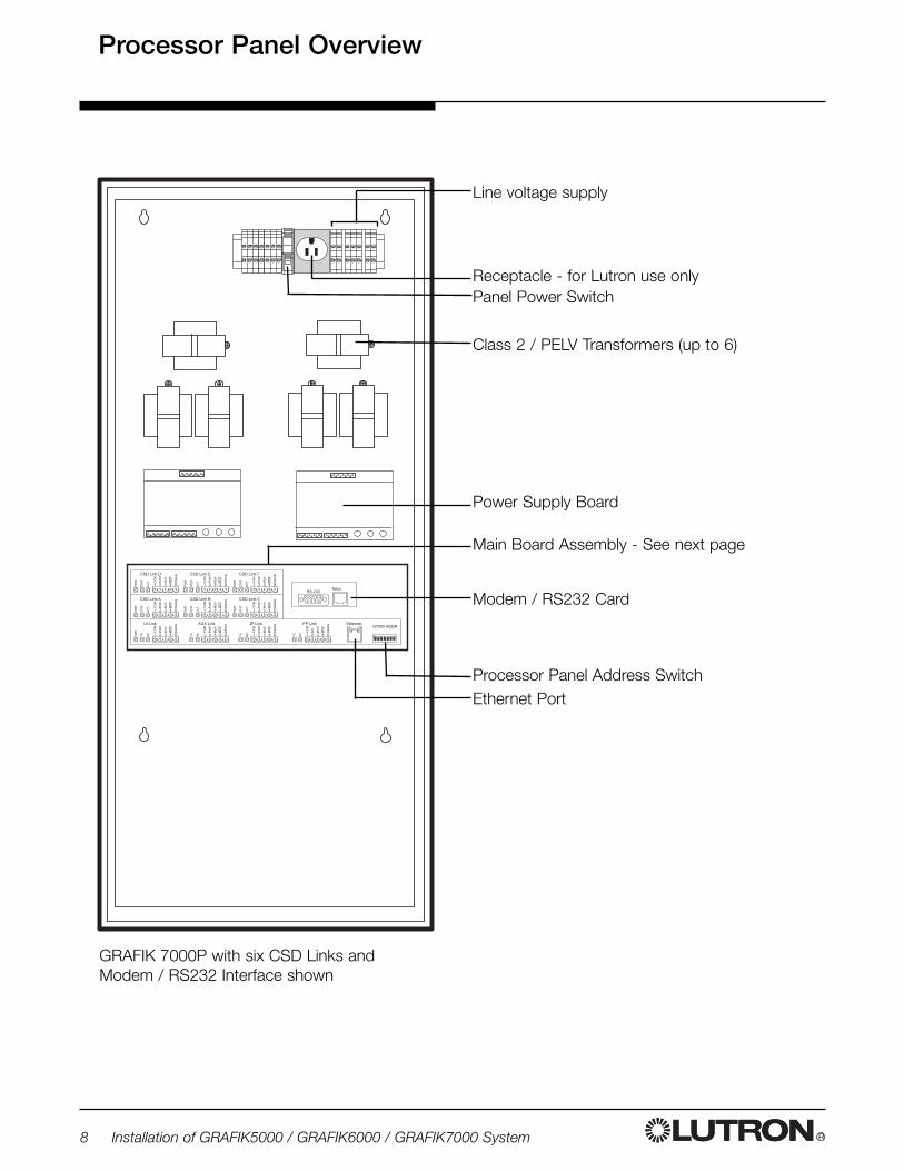
Line voltage supply
Receptacle - for Lutron use onlyPanel Power Switch
Power Supply Board
Main Board Assembly - See next page
Class 2 / PELV Transformers (up to 6)
Processor Panel Address Switch
Modem / RS232 Card
Ethernet Port
GRAFIK 7000P with six CSD Links and Modem / RS232 Interface shown
R Installation of GRAFIK5000 / GRAFIK6000 / GRAFIK7000 System 9
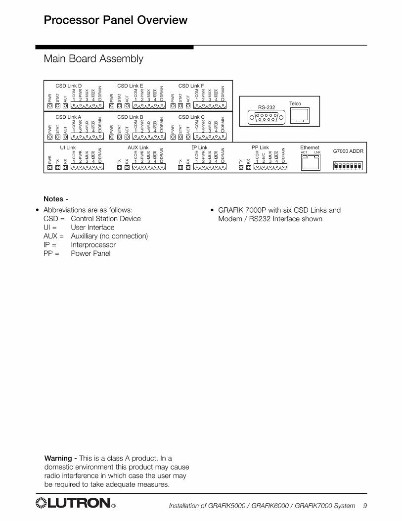
Notes -
• Abbreviations are as follows:CSD = Control Station DeviceUI = User InterfaceAUX = Auxilliary (no connection)IP = InterprocessorPP = Power Panel
��
�
���
�
��
� �
��
�
�
�
�
�
�
���
� � � �
�� ������
��
�
���
�
��
� �
��
�
�
�
�
�
�
���
� � � �
�� �������
��
�
���
�
��
� �
��
�
�
�
�
�
�
���
� � � �
�� �������
��
�
���
�
��
� �
��
�
�
�
�
�
�
���
� � � �
�� ��������
��
���
�
��
� �
��
�
�
�
�
�
�
���
� � � �
�� �������
��
�
���
�
��
� �
��
�
�
�
�
�
�
���
� � � �
�� �������
��
��
�
���
�
�
�
�
�
���
� � � �
�������
��
��
�
��
�
�
�
�
�
�
���
� � � �
�������� ���� ������ ��!
��
��
�
��
�
�
�
�
�
�
���
� � � �
�������
��
�
��
��
�
��
�
�
�
�
�
�
���
� � � �
�������
��"�����#$%
&'(((�� �
� � � � ) * '
�
• GRAFIK 7000P with six CSD Links andModem / RS232 Interface shown
Processor Panel Overview
Main Board Assembly
Warning - This is a class A product. In adomestic environment this product may causeradio interference in which case the user maybe required to take adequate measures.
RS485 Wiring Overview
R10 Installation of GRAFIK5000 / GRAFIK6000 / GRAFIK7000 System
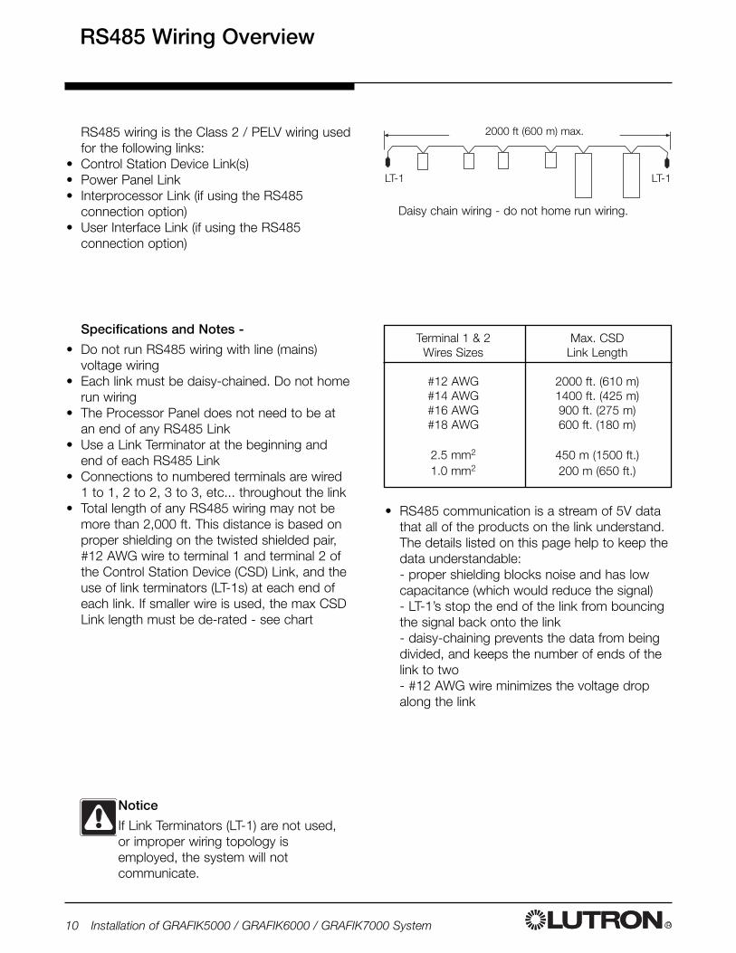
2000 ft (600 m) max.
Terminal 1 & 2Wires Sizes
#12 AWG#14 AWG#16 AWG#18 AWG
2.5 mm2
1.0 mm2
Max. CSDLink Length
2000 ft. (610 m)1400 ft. (425 m)900 ft. (275 m)600 ft. (180 m)
450 m (1500 ft.)200 m (650 ft.)
Notice
If Link Terminators (LT-1) are not used,or improper wiring topology isemployed, the system will notcommunicate.
Daisy chain wiring - do not home run wiring.
RS485 wiring is the Class 2 / PELV wiring usedfor the following links:
• Control Station Device Link(s)• Power Panel Link• Interprocessor Link (if using the RS485
connection option)• User Interface Link (if using the RS485
connection option)
Specifications and Notes -
• Do not run RS485 wiring with line (mains)voltage wiring
• Each link must be daisy-chained. Do not homerun wiring
• The Processor Panel does not need to be atan end of any RS485 Link
• Use a Link Terminator at the beginning andend of each RS485 Link
• Connections to numbered terminals are wired1 to 1, 2 to 2, 3 to 3, etc... throughout the link
• Total length of any RS485 wiring may not bemore than 2,000 ft. This distance is based onproper shielding on the twisted shielded pair,#12 AWG wire to terminal 1 and terminal 2 ofthe Control Station Device (CSD) Link, and theuse of link terminators (LT-1s) at each end ofeach link. If smaller wire is used, the max CSDLink length must be de-rated - see chart
• RS485 communication is a stream of 5V datathat all of the products on the link understand.The details listed on this page help to keep thedata understandable:- proper shielding blocks noise and has lowcapacitance (which would reduce the signal)- LT-1’s stop the end of the link from bouncingthe signal back onto the link- daisy-chaining prevents the data from beingdivided, and keeps the number of ends of thelink to two- #12 AWG wire minimizes the voltage dropalong the link
LT-1 LT-1
����
RS485 Wiring Overview
R Installation of GRAFIK5000 / GRAFIK6000 / GRAFIK7000 System 11
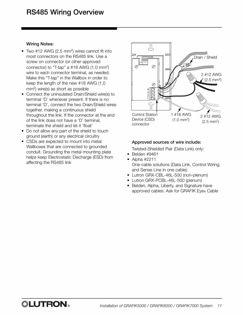
Wiring Notes:
• Two #12 AWG (2.5 mm2) wires cannot fit intomost connectors on the RS485 link. Use ascrew on connector (or other approvedconnector) to “T-tap” a #18 AWG (1.0 mm2)wire to each connector terminal, as needed.Make this “T-tap” in the Wallbox in order tokeep the length of the new #18 AWG (1.0mm2) wire(s) as short as possible
• Connect the uninsulated Drain/Shield wire(s) toterminal ‘D’ whenever present. If there is noterminal ‘D’, connect the two Drain/Shield wirestogether, making a continuous shieldthroughout the link. If the connector at the endof the link does not have a ‘D’ terminal,terminate the shield and let it ‘float’
• Do not allow any part of the shield to touchground (earth) or any electrical circuitry
• CSDs are expected to mount into metalWallboxes that are connected to groundedconduit. Grounding the metal mounting platehelps keep Electrostatic Discharge (ESD) fromaffecting the RS485 link
Control StationDevice (CSD)connector
Drain / Shield
1 #18 AWG(1.0 mm2)
2 #12 AWG(2.5 mm2)
2 #12 AWG(2.5 mm2)
Approved sources of wire include:
Twisted-Shielded Pair (Data Link) only:• Belden #9461• Alpha #2211
One-cable solutions (Data Link, Control Wiring,and Sense Line in one cable):
• Lutron GRX-CBL-46L-500 (non-plenum)• Lutron GRX-PCBL-46L-500 (plenum)• Belden, Alpha, Liberty, and Signature have
approved cables. Ask for GRAFIK Eye® Cable
R12 Installation of GRAFIK5000 / GRAFIK6000 / GRAFIK7000 System
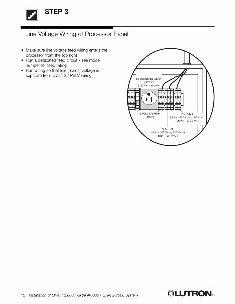
• Make sure line voltage feed wiring enters theprocessor from the top right
• Run a dedicated feed circuit - see modelnumber for feed rating
• Run wiring so that line (mains) voltage isseparate from Class 2 / PELV wiring
HOT/LIVE(black - 100 V , 120 V )
(brown - 230 V )
NEUTRAL(white - 100 V , 120 V )
(blue - 230 V )
GROUND/EARTH(green)
Receptacle for Lutronuse only
(120 V shown)
Line Voltage Wiring of Processor Panel
STEP 3
R Installation of GRAFIK5000 / GRAFIK6000 / GRAFIK7000 System 13
��
�
���
�
��
� �
��
�
�
�
�
�
�
���
� � � �
�� ������
��
�
���
�
��
� �
��
�
�
�
�
�
�
���
� � � �
�� �������
��
�
���
�
��
� �
��
�
�
�
�
�
�
���
� � � �
�� �������
��
�
���
�
��
� �
��
�
�
�
�
�
�
���
� � � �
�� �������
��
�
���
�
��
� �
��
�
�
�
�
�
�
���
� � � �
�� �������
��
�
���
�
��
� �
��
�
�
�
�
�
�
���
� � � �
�� �������
��
��
�
���
�
�
�
�
�
���
� � � �
�������
��
��
�
��
�
�
�
�
�
�
���
� � � �
�������� ���� ������ ��!
��
��
�
��
�
�
�
�
�
�
���
� � � �
�������
��
�
��
��
�
��
�
�
�
�
�
�
���
� � � �
�������
��"�����#$%
&'(((�� �
� � � � ) * '
�
� � � � ) *
����
� �
� �
��
%++
%��
���
�
��
�
��
,��
)�
��-�
����
�
��
%++
%��
���
�
��
�
��
,��
)�
��-�
����
�
��
%++
%��
���
�
��
�
��
,��
)�
��-�
����
�
��
��
)*
����
� �
� �
� � � � � � �) � *
�������
�
���
�
�
�
�
�
���
� � � �
�� ������
��
�
�
�
�
�
�
���
� � � �
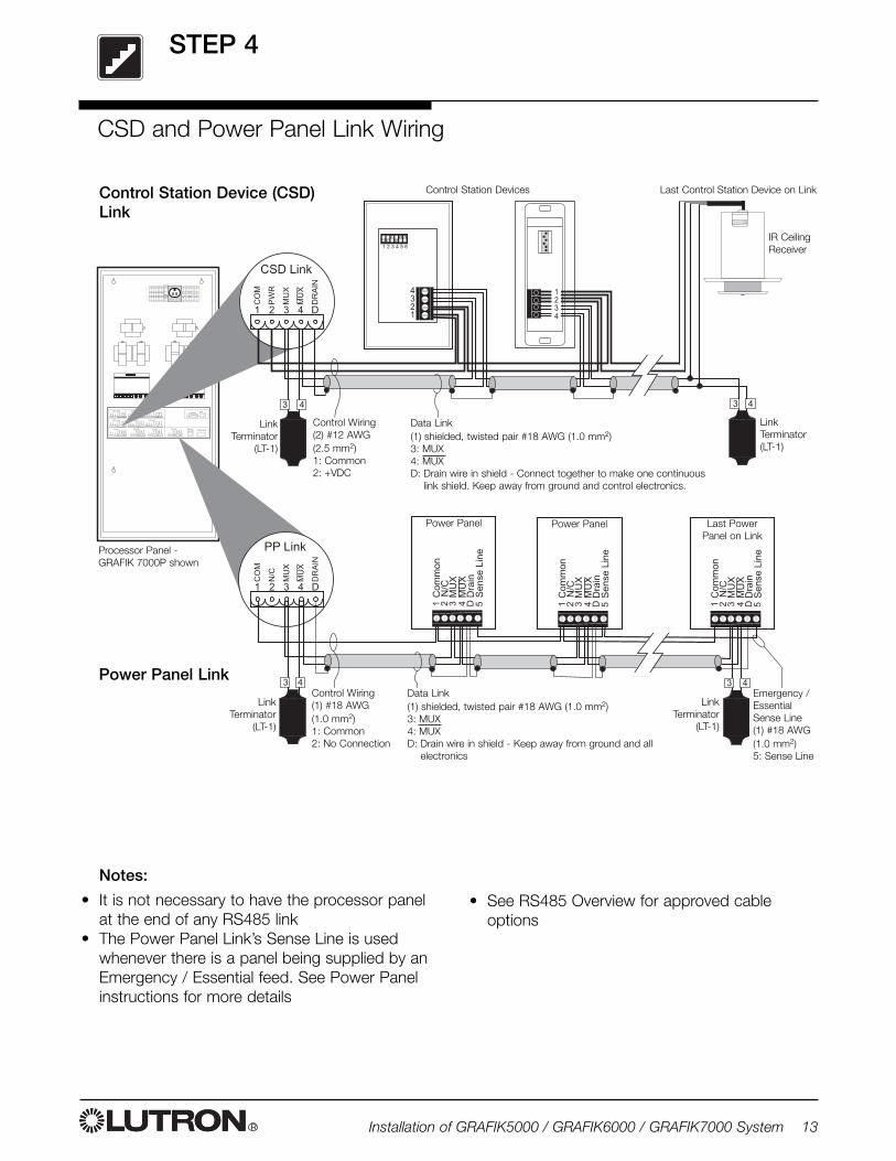
Control Wiring(2) #12 AWG(2.5 mm2)1: Common2: +VDC
Last Control Station Device on Link
Data Link(1) shielded, twisted pair #18 AWG (1.0 mm2)3: MUX4: MUXD: Drain wire in shield - Connect together to make one continuous
link shield. Keep away from ground and control electronics.
LinkTerminator
(LT-1)
LinkTerminator(LT-1)
Control Station Device (CSD)Link
Control Station Devices
Power Panel LinkData Link(1) shielded, twisted pair #18 AWG (1.0 mm2)3: MUX4: MUXD: Drain wire in shield - Keep away from ground and all
electronics
Control Wiring(1) #18 AWG(1.0 mm2)1: Common2: No Connection
IR CeilingReceiver
LinkTerminator
(LT-1)
LinkTerminator
(LT-1)
Notes:
• It is not necessary to have the processor panelat the end of any RS485 link
• The Power Panel Link’s Sense Line is usedwhenever there is a panel being supplied by anEmergency / Essential feed. See Power Panelinstructions for more details
• See RS485 Overview for approved cableoptions
Power Panel Power Panel Last PowerPanel on Link
CSD and Power Panel Link Wiring
Emergency /EssentialSense Line(1) #18 AWG(1.0 mm2)5: Sense Line
STEP 4
Processor Panel -GRAFIK 7000P shown
STEP 5
R14 Installation of GRAFIK5000 / GRAFIK6000 / GRAFIK7000 System
��
�
���
�
��
� �
��
�
�
�
�
�
�
���
� � � �
�� ������
��
�
���
�
��
� �
��
�
�
�
�
�
�
���
� � � �
�� �������
��
�
���
�
��
� �
��
�
�
�
�
�
�
���
� � � �
�� �������
��
�
���
�
��
� �
��
�
�
�
�
�
�
���
� � � �
�� �������
��
�
���
�
��
� �
��
�
�
�
�
�
�
���
� � � �
�� �������
��
�
���
�
��
� �
��
�
�
�
�
�
�
���
� � � �
�� �������
��
��
�
���
�
�
�
�
�
���
� � � �
�������
��
��
�
��
�
�
�
�
�
�
���
� � � �
�������� ���� ������ ��!
��
��
�
��
�
�
�
�
�
�
���
� � � �
�������
��
�
��
��
�
��
�
�
�
�
�
�
���
� � � �
�������
��"�����#$%
&'(((�� �
� � � � ) * '
�
�������&.���&�����
���/)���
� � � �
�������
�
��
�
�
�
�
�
�
���
� � � �
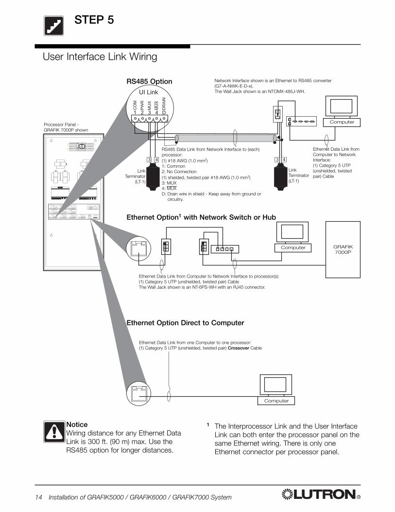
RS485 Option
Ethernet Option Direct to Computer
RS485 Data Link from Network Interface to (each)processor:(1) #18 AWG (1.0 mm2)1: Common2: No Connection(1) shielded, twisted pair #18 AWG (1.0 mm2)3: MUX4: MUXD: Drain wire in shield - Keep away from ground or
circuitry.
Ethernet Data Link fromComputer to NetworkInterface:(1) Category 5 UTP(unshielded, twistedpair) Cable
Network Interface shown is an Ethernet to RS485 converter (G7-A-NWK-E-D-x).The Wall Jack shown is an NTOMX-485J-WH.
GRAFIK7000P
Computer
Computer
Computer
Ethernet Data Link from Computer to Network Interface to processor(s):(1) Category 5 UTP (unshielded, twisted pair) CableThe Wall Jack shown is an NT-6PS-WH with an RJ45 connector.
Ethernet Data Link from one Computer to one processor:(1) Category 5 UTP (unshielded, twisted pair) Crossover Cable
Ethernet Option1 with Network Switch or Hub
NoticeWiring distance for any Ethernet DataLink is 300 ft. (90 m) max. Use theRS485 option for longer distances.
User Interface Link Wiring
1 The Interprocessor Link and the User InterfaceLink can both enter the processor panel on thesame Ethernet wiring. There is only oneEthernet connector per processor panel.
LinkTerminator
(LT-1)
LinkTerminator(LT-1)
Processor Panel -GRAFIK 7000P shown
STEP 6
R Installation of GRAFIK5000 / GRAFIK6000 / GRAFIK7000 System 15
��
�
���
�
��
� �
��
�
�
�
�
�
�
���
� � � �
�� ������
��
�
���
�
��
� �
��
�
�
�
�
�
�
���
� � � �
�� �������
��
�
���
�
��
� �
��
�
�
�
�
�
�
���
� � � �
�� �������
��
�
���
�
��
� �
��
�
�
�
�
�
�
���
� � � �
�� �������
��
�
���
�
��
� �
��
�
�
�
�
�
�
���
� � � �
�� �������
��
�
���
�
��
� �
��
�
�
�
�
�
�
���
� � � �
�� �������
��
��
�
���
�
�
�
�
�
���
� � � �
�������
��
��
�
��
�
�
�
�
�
�
���
� � � �
�������� ���� ������ ��!
��
��
�
��
�
�
�
�
�
�
���
� � � �
�������
��
�
��
��
�
��
�
�
�
�
�
�
���
� � � �
�������
��"�����#$%
&'(((�� �
� � � � ) * '
�
��������������
� � � �
�������
�
��
�
�
�
�
�
�
���
� � � �
�
��
��
�
�
�
�
�
���
� � � �
�������
�
��
�
�
�
�
�
�
���
� � � �
�
��
�
�
�
�
�
�
���
� � � �
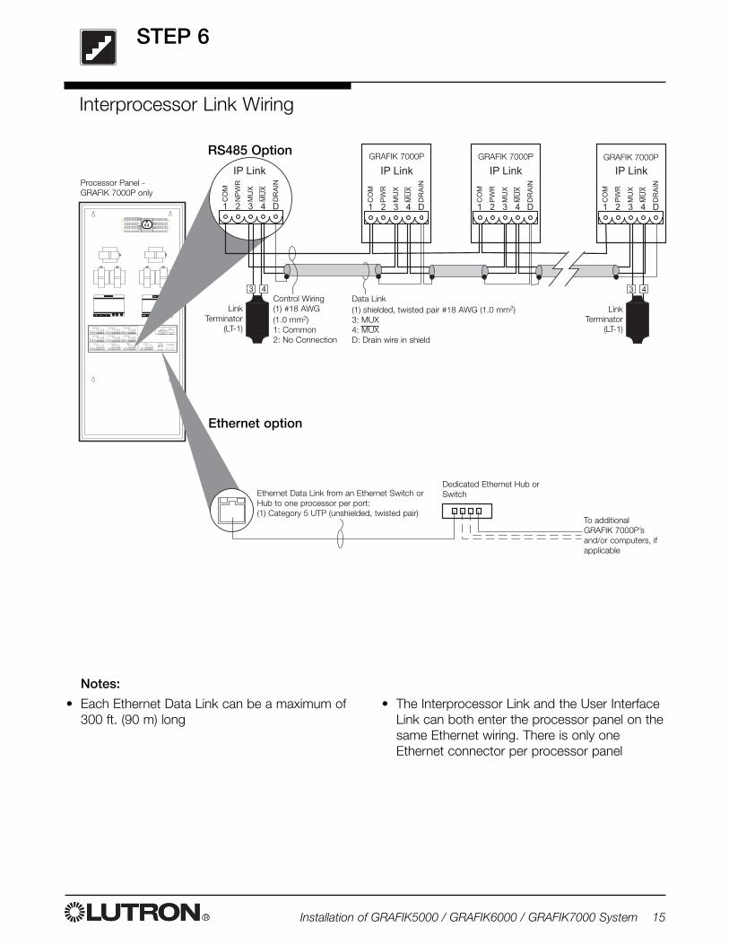
Processor Panel -GRAFIK 7000P only
LinkTerminator
(LT-1)
To additional GRAFIK 7000P’sand/or computers, ifapplicable
GRAFIK 7000P GRAFIK 7000P GRAFIK 7000P
Data Link(1) shielded, twisted pair #18 AWG (1.0 mm2)3: MUX4: MUXD: Drain wire in shield
Control Wiring(1) #18 AWG(1.0 mm2)1: Common2: No Connection
Ethernet option
LinkTerminator
(LT-1)
Ethernet Data Link from an Ethernet Switch orHub to one processor per port:(1) Category 5 UTP (unshielded, twisted pair)
Dedicated Ethernet Hub orSwitch
Notes:
• Each Ethernet Data Link can be a maximum of300 ft. (90 m) long
• The Interprocessor Link and the User InterfaceLink can both enter the processor panel on thesame Ethernet wiring. There is only oneEthernet connector per processor panel
Interprocessor Link Wiring
RS485 Option
STEP 7
R16 Installation of GRAFIK5000 / GRAFIK6000 / GRAFIK7000 System
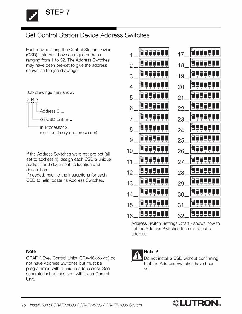
Each device along the Control Station Device(CSD) Link must have a unique addressranging from 1 to 32. The Address Switchesmay have been pre-set to give the addressshown on the job drawings.
Set Control Station Device Address Switches
�'
�/
�0
�(
��
��
��
��
�)
�*
�'
�/
�0
�(
��
��
� � � � ) * '
�
� � � � ) * '
�
� � � � ) * '
�
� � � � ) * '
�
� � � � ) * '
�
� � � � ) * '
�
� � � � ) * '
�
� � � � ) * '
�
� � � � ) * '
�
� � � � ) * '
�
� � � � ) * '
�
� � � � ) * '
�
� � � � ) * '
�
� � � � ) * '
�
� � � � ) * '
�
� � � � ) * '
�
0
�(
��
��
��
��
�)
�*
� � � � ) * '
�
� � � � ) * '
�
� � � � ) * '
�
� � � � ) * '
�
� � � � ) * '
�
� � � � ) * '
�
� � � � ) * '
�
� � � � ) * '
�
� � � � ) * '
�
� � � � ) * '
�
� � � � ) * '
�
� � � � ) * '
�
� � � � ) * '
�
� � � � ) * '
�
� � � � ) * '
�
� � � � ) * '
�
�
�
�
�
)
*
'
/
Address Switch Settings Chart - shows how toset the Address Switches to get a specificaddress.
Notice!
Do not install a CSD without confirmingthat the Address Switches have beenset.
If the Address Switches were not pre-set (allset to address 1), assign each CSD a uniqueaddress and document its location anddescription.If needed, refer to the instructions for eachCSD to help locate its Address Switches.
2 B 3
Job drawings may show:
Address 3 ...
on CSD Link B ...
in Processor 2(omitted if only one processor)
Note
GRAFIK Eye® Control Units (GRX-46xx-x-xx) donot have Address Switches but must beprogrammed with a unique address(es). Seeseparate instructions sent with each ControlUnit.
STEP 8
R Installation of GRAFIK5000 / GRAFIK6000 / GRAFIK7000 System 17
��
�
���
�
��
� �
��
�
�
�
�
�
�
���
� � � �
�� ������
��
�
���
�
��
� �
��
�
�
�
�
�
�
���
� � � �
�� �������
��
�
���
�
��
� �
��
�
�
�
�
�
�
���
� � � �
�� �������
��
�
���
�
��
� �
��
�
�
�
�
�
�
���
� � � �
�� �������
��
�
���
�
��
� �
��
�
�
�
�
�
�
���
� � � �
�� �������
��
�
���
�
��
� �
��
�
�
�
�
�
�
���
� � � �
�� �������
��
��
�
���
�
�
�
�
�
���
� � � �
�������
��
��
�
��
�
�
�
�
�
�
���
� � � �
�������� ���� ������ ��!
��
��
�
��
�
�
�
�
�
�
���
� � � �
�������
��
�
��
��
�
��
�
�
�
�
�
�
���
� � � �
�������
��"�����#$%
&'(((�� �
� � � � ) * '
�
� � � � ) * '
�
����������
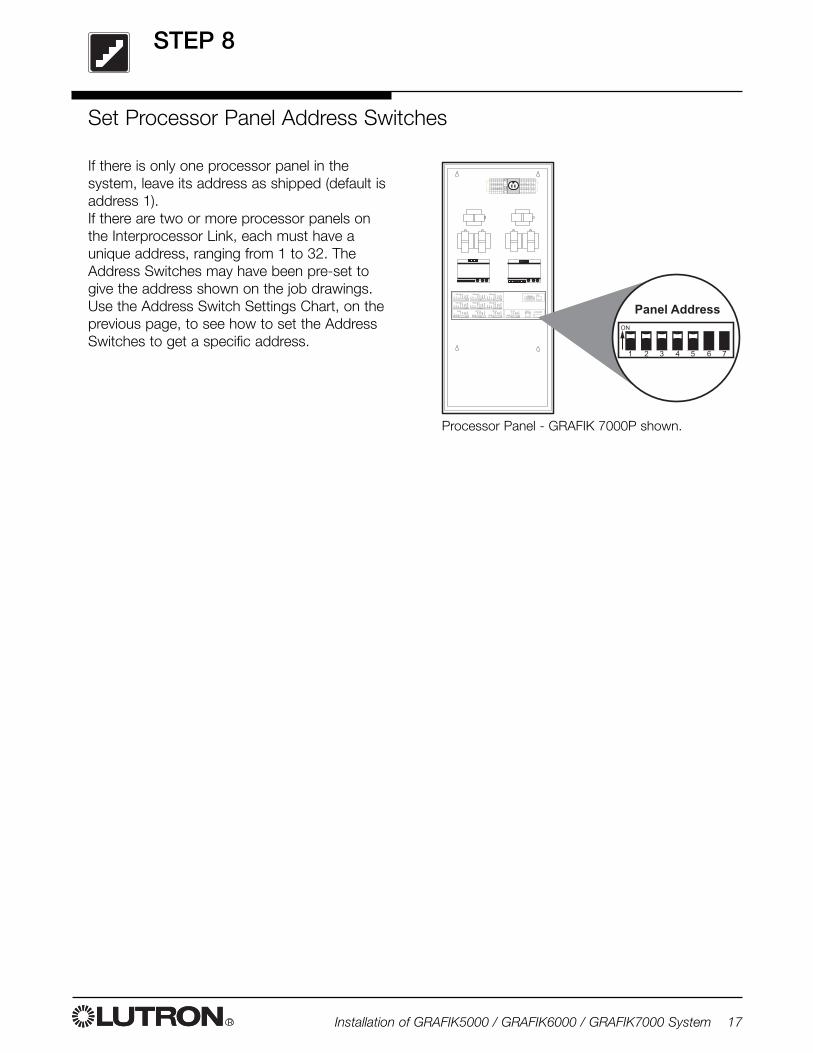
Set Processor Panel Address Switches
If there is only one processor panel in thesystem, leave its address as shipped (default isaddress 1).If there are two or more processor panels onthe Interprocessor Link, each must have aunique address, ranging from 1 to 32. TheAddress Switches may have been pre-set togive the address shown on the job drawings.Use the Address Switch Settings Chart, on theprevious page, to see how to set the AddressSwitches to get a specific address.
Processor Panel - GRAFIK 7000P shown.
STEP 9
R18 Installation of GRAFIK5000 / GRAFIK6000 / GRAFIK7000 System
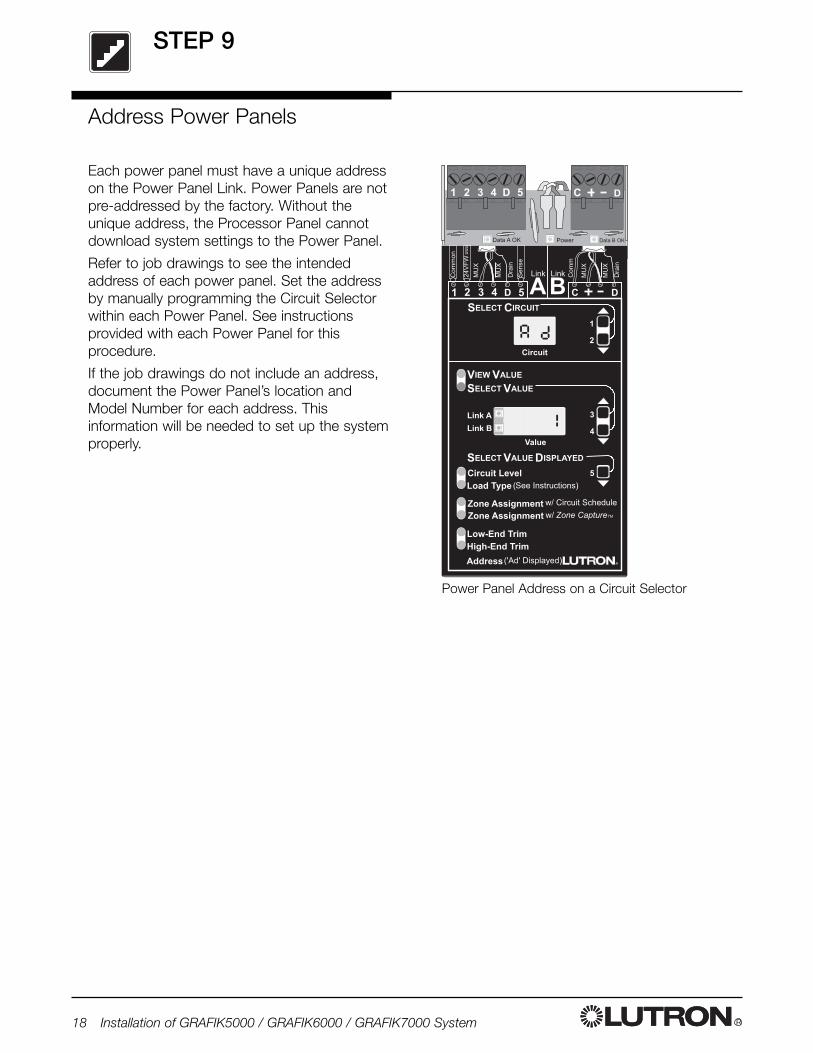
Address Power Panels
Each power panel must have a unique addresson the Power Panel Link. Power Panels are notpre-addressed by the factory. Without theunique address, the Processor Panel cannotdownload system settings to the Power Panel.
Refer to job drawings to see the intendedaddress of each power panel. Set the addressby manually programming the Circuit Selectorwithin each Power Panel. See instructionsprovided with each Power Panel for thisprocedure.
If the job drawings do not include an address,document the Power Panel’s location andModel Number for each address. Thisinformation will be needed to set up the systemproperly.
,�,���! ,�,���!�%1�
� � � �� � �
���������
������������
����� ���!��
��"��������
�
�
#����
���$��
���$�%
�
�
�����
�%
�%+
+%�
��2
��
�
�
�
�
,
��
���
-�
�%+
+
,
��
�
�
�
�
�� � � � � �
���� ����
34�54� �-6#,7�58����
&����������� 1� �� $9����$��59#�
&����������� ��1� �������� �
�3������-� 9$��%�-8
'����� �()�*(�
'����� #��*�
#(�+ #��*�
'����� #��*� �('���,��
Power Panel Address on a Circuit Selector
R Installation of GRAFIK5000 / GRAFIK6000 / GRAFIK7000 System 19
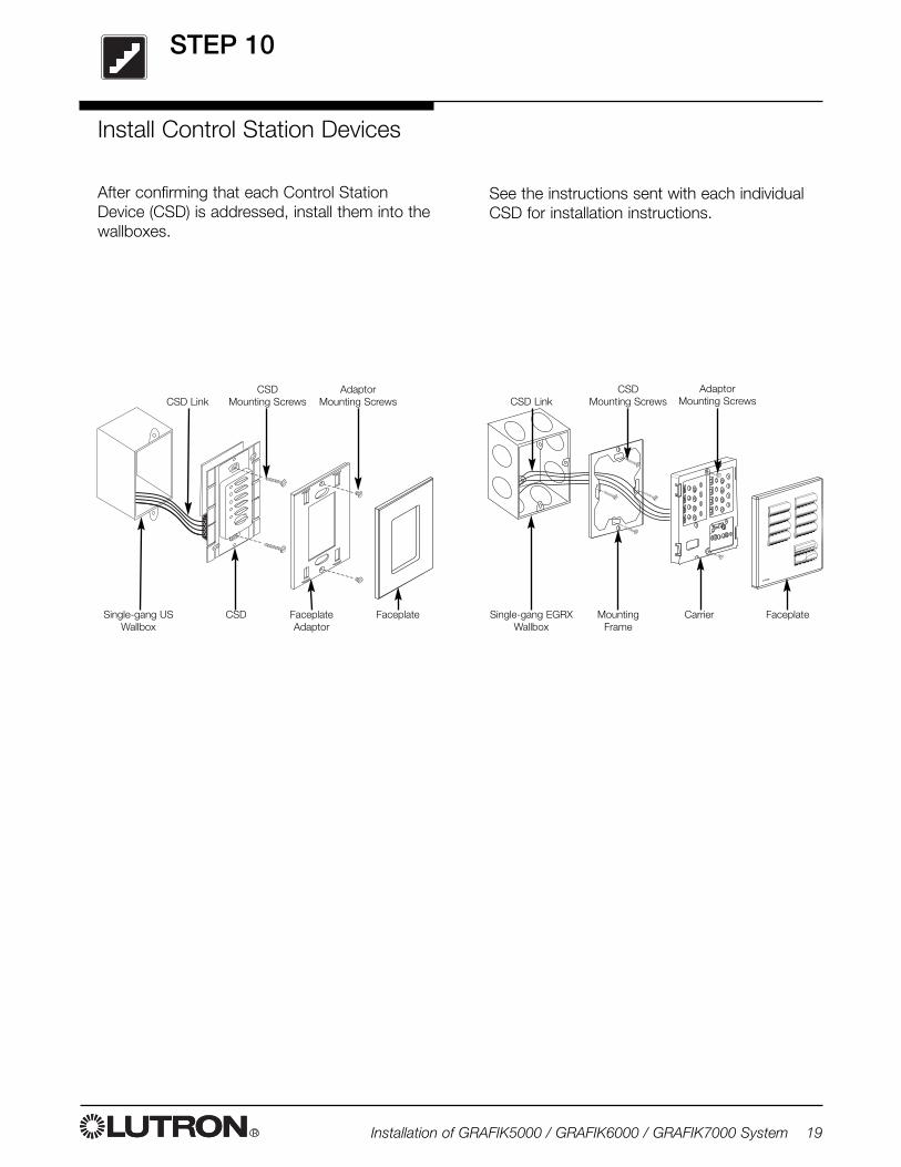
Single-gang USWallbox
CSD
CSD Mounting Screws
Adaptor Mounting Screws
FaceplateAdaptor
Faceplate
CSD Link
After confirming that each Control StationDevice (CSD) is addressed, install them into thewallboxes.
Install Control Station Devices
See the instructions sent with each individualCSD for installation instructions.
STEP 10
CSD Mounting Screws
Adaptor Mounting ScrewsCSD Link
Single-gang EGRXWallbox
MountingFrame
Carrier Faceplate
��
�
���
�
��
� �
��
�
�
�
�
�
�
���
� � � �
�� ������
��
�
���
�
��
� �
��
�
�
�
�
�
�
���
� � � �
�� �������
��
�
���
�
��
� �
��
�
�
�
�
�
�
���
� � � �
�� �������
��
�
���
�
��
� �
��
�
�
�
�
�
�
���
� � � �
�� �������
��
�
���
�
��
� �
��
�
�
�
�
�
�
���
� � � �
�� �������
��
�
���
�
��
� �
��
�
�
�
�
�
�
���
� � � �
�� �������
��
��
�
���
�
�
�
�
�
���
� � � �
�������
��
��
�
��
�
�
�
�
�
�
���
� � � �
�������� ���� ������ ��!
��
��
�
��
�
�
�
�
�
�
���
� � � �
�������
��
�
��
��
�
��
�
�
�
�
�
�
���
� � � �
�������
��"�����#$%
&'(((�� �
� � � � ) * '
�
��
��
�
���
�
�
�
�
�
���
� � � �
�������
����!
����!
����!
��
�
���
�
��
� �
��
�
�
�
�
�
�
���
� � � �
�� ������
��
�
��
��
�
��
�
�
�
�
�
�
���
� � � �
�������
STEP 11
R20 Installation of GRAFIK5000 / GRAFIK6000 / GRAFIK7000 System
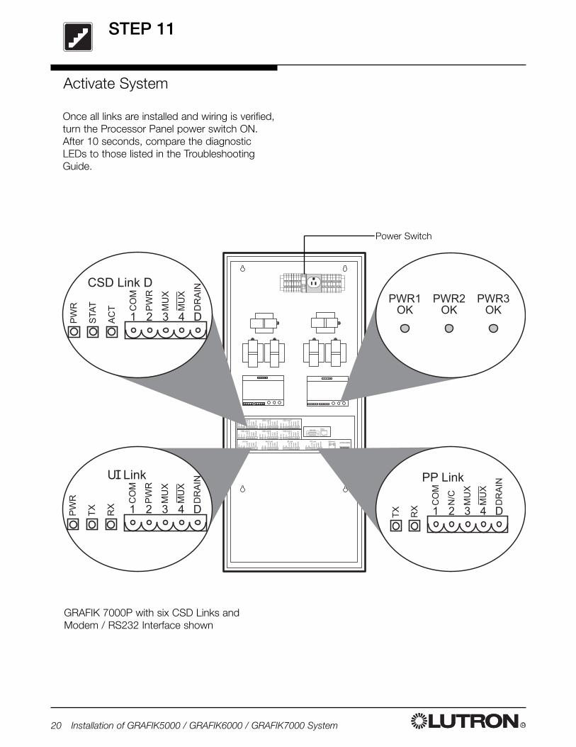
Activate System
Once all links are installed and wiring is verified,turn the Processor Panel power switch ON.After 10 seconds, compare the diagnosticLEDs to those listed in the TroubleshootingGuide.
GRAFIK 7000P with six CSD Links andModem / RS232 Interface shown
Power Switch
Troubleshooting Guide
R Installation of GRAFIK5000 / GRAFIK6000 / GRAFIK7000 System 21
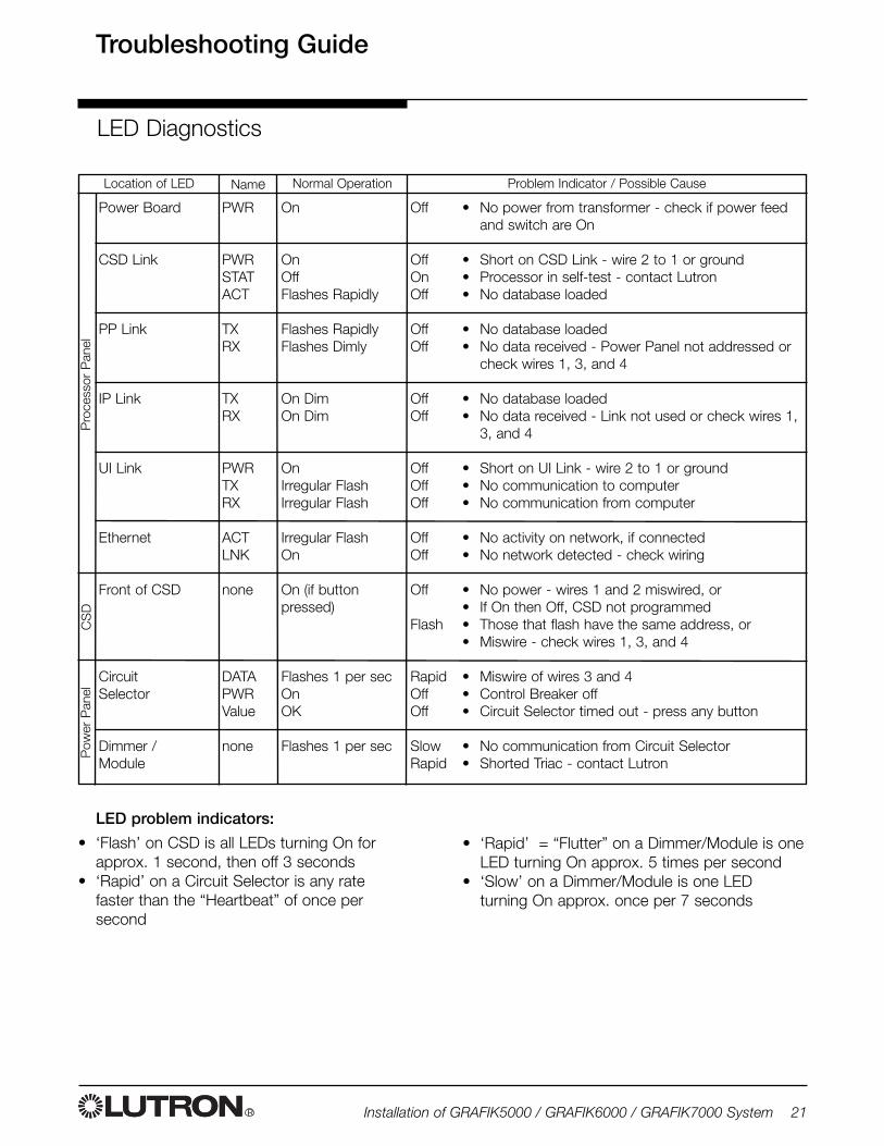
Location of LED
Power Board
CSD Link
PP Link
IP Link
UI Link
Ethernet
Front of CSD
CircuitSelector
Dimmer /Module
Problem Indicator / Possible CauseName Normal Operation
PWR
PWRSTATACT
TXRX
TXRX
PWRTXRX
ACTLNK
none
DATAPWRValue
none
On
OnOffFlashes Rapidly
Flashes RapidlyFlashes Dimly
On DimOn Dim
OnIrregular FlashIrregular Flash
Irregular FlashOn
On (if buttonpressed)
Flashes 1 per secOnOK
Flashes 1 per sec
Off
OffOnOff
OffOff
OffOff
OffOffOff
OffOff
Off
Flash
RapidOffOff
SlowRapid
• No power from transformer - check if power feedand switch are On
• Short on CSD Link - wire 2 to 1 or ground• Processor in self-test - contact Lutron• No database loaded
• No database loaded• No data received - Power Panel not addressed or
check wires 1, 3, and 4
• No database loaded• No data received - Link not used or check wires 1,
3, and 4
• Short on UI Link - wire 2 to 1 or ground• No communication to computer• No communication from computer
• No activity on network, if connected• No network detected - check wiring
• No power - wires 1 and 2 miswired, or• If On then Off, CSD not programmed• Those that flash have the same address, or• Miswire - check wires 1, 3, and 4
• Miswire of wires 3 and 4• Control Breaker off• Circuit Selector timed out - press any button
• No communication from Circuit Selector• Shorted Triac - contact Lutron
LED Diagnostics
Pro
cess
or P
anel
CS
DP
ower
Pan
el
LED problem indicators:
• ‘Flash’ on CSD is all LEDs turning On forapprox. 1 second, then off 3 seconds
• ‘Rapid’ on a Circuit Selector is any ratefaster than the “Heartbeat” of once persecond
• ‘Rapid’ = “Flutter” on a Dimmer/Module is oneLED turning On approx. 5 times per second
• ‘Slow’ on a Dimmer/Module is one LEDturning On approx. once per 7 seconds
R22 Installation of GRAFIK5000 / GRAFIK6000 / GRAFIK7000 System
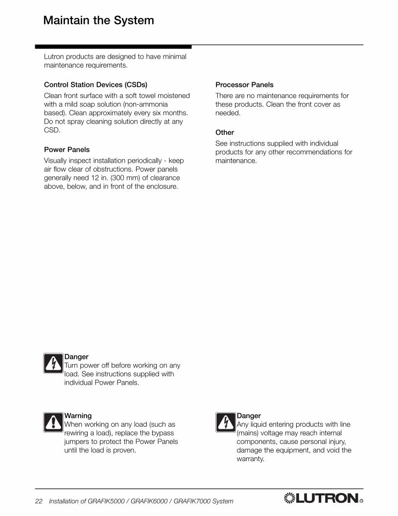
Processor Panels
There are no maintenance requirements forthese products. Clean the front cover asneeded.
Other
See instructions supplied with individualproducts for any other recommendations formaintenance.
Lutron products are designed to have minimalmaintenance requirements.
Control Station Devices (CSDs)
Clean front surface with a soft towel moistenedwith a mild soap solution (non-ammoniabased). Clean approximately every six months.Do not spray cleaning solution directly at anyCSD.
Power Panels
Visually inspect installation periodically - keepair flow clear of obstructions. Power panelsgenerally need 12 in. (300 mm) of clearanceabove, below, and in front of the enclosure.
Maintain the System
WarningWhen working on any load (such asrewiring a load), replace the bypassjumpers to protect the Power Panelsuntil the load is proven.
DangerAny liquid entering products with line(mains) voltage may reach internalcomponents, cause personal injury,damage the equipment, and void thewarranty.
DangerTurn power off before working on anyload. See instructions supplied withindividual Power Panels.

R Installation of GRAFIK5000 / GRAFIK6000 / GRAFIK7000 System 23
Notes -
R
Internet: www.lutron.comE-mail: [email protected]
WORLD HEADQUARTERSLutron Electronics Co. Inc.,TOLL FREE: 1.800.523.9466(U.S.A., Canada, portions of Caribbean)Tel: 1.610.282.3800Fax: 1.610.282.3090
GREAT BRITAINLutron EA Ltd.,Tel: +44.207.702.0657Fax: +44.207.480.6899
GERMANYLutron Electronics GmbHTel: +49.309.710.4590Fax: +49.309.710.4591
JAPAN SALES OFFICELutron Asuka CorporationTel: +813.5405.7333Fax: +813.5405.7496
HONG KONG SALES OFFICELutron GL (Hong Kong)Tel: +852.2104.7733Fax: +852.2104.7633
SINGAPORELutron GL (Singapore)Tel: +65.220.4666Fax: +65.220.4333
LIMITED WARRANTYLutron will, at its option, repair or replace any unit that is defective inmaterials or manufacture within one year after purchase. Forwarranty service, return unit to place of purchase or mail to Lutron at7200 Suter Rd., Coopersburg, PA 18036-1299, postage pre-paid.This warranty is in lieu of all other express warranties, and theimplied warranty of merchantability is limited to one year frompurchase. This warranty does not cover the cost of installation,removal or reinstallation, or damage resulting from misuse,abuse, or improper or incorrect repair, or damage fromimproper wiring or installation. This warranty does not coverincidental or consequential damages. Lutron’s liability on anyclaim for damages arising out of or in connection with themanufacture, sale, installation, delivery, or use of the unit shallnever exceed the purchase price of the unit.This warranty gives you specific legal rights, and you may also haveother rights which vary from state to state. Some states do not allowlimitations on how long an implied warranty lasts, so the abovelimitation may not apply to you. Some states do not allow theexclusion or limitation of incidental or consequential damages, so theabove limitation or exclusion may not apply to you. This product maybe covered by one or more of the following U.S. patents: 4,797,599;4,803,380; 4,825,075; 4,893,062; 5,030,893; 5,191,265; 5,430,356;5,463,286; 5,530,322; 5,808,417; DES 308,647; DES 310,349; DES311,170; DES 311,371; DES 311,382; DES 311,485; DES 311,678;DES 313,738; DES 335,867; DES 344,264; CES 370,663; DES378,814 and corresponding foreign patents. U.S. and foreignpatents pending.Lutron, GRAFIK6000, and GRAFIK Eye are registered trademarks;GRAFIK5000, GRAFIK7000, and 2Link are trademarks of LutronElectronics Co., Inc. © 2004 Lutron Electronics Co., Inc.
Lutron Electronics Co., Inc.Made and printed in U.S.A.P/N 032-120 Rev. A - 2/19/04
Contact InformationWarranty