Embed Size (px)
Citation preview

Lighting Management SolutionsProducts & systems catalogue
PUTTING A STOP TO ENERGY WASTE

Putting a stop to energy waste
CONTENTS
Our vision ............................................................................................................................p3
Why implement Lighting Management? ............................................................................p4
Requirements for implementing Lighting Management ..................................................p6
How to implement Lighting Management ? ....................................................................p10
Lighting Management products & systems ....................................................................p12
Related services ...............................................................................................................p26
Catalogue pages ...............................................................................................................p28
Glossary ............................................................................................................................p45

3LI
GHTI
NG M
ANAG
EMEN
T SO
LUTI
ONS
| P
RODU
CTS
& SY
STEM
S CA
TALO
G
OUR VISION
Our vision at Legrand is to provide products and services that make buildings
more energy-efficient.
We are committed to putting a stop to energy waste.
Energy-efficient lighting management systems ensure there is just the right amount of light when and where you
need it. They are reliable and easy to use, provide safety and security, reduce expenses and are code compliant,
sustainable and environmentally friendly.
Legrand offers two types of solutions and proposes related services to ensure that your lighting management
project saves energy and helps the environment.
Switch sensors
BUS | SCS systems

Lighting is a significant user of energy
in commercial buildings 20% of total site energy is consumed by lighting.
Lighting is the first electricity end-user with up to
40% electricity consumed.*
*Energy end-use distribution varies greatly depending on the activity of the building and across
geographical and climate regions (Source: Energy Information Administration, USA)
WHY IMPLEMENT LIGHTING MANAGEMENT?

5LI
GHTI
NG M
ANAG
EMEN
T SO
LUTI
ONS
| P
RODU
CTS
& SY
STEM
S CA
TALO
G
Each year, increasing numbers of organisations implement lighting
management because they recognise its wide range of benefits:
Together with heating and air conditioning, lighting accounts for the greatest
energy consumption and costs of a building. These significant costs can be more
effectively controlled through the use of lighting management.
Energy savingsPerhaps the primary benefit is that of energy savings. Lighting
management can result in energy savings of more than
30%, reducing building operating costs by 10% or more(1).
Energy waste can be eliminated by using automatic lighting
management so that lights work intelligently: the right levels
in the right locations, at precisely the right times.
Economic savingsReduced lighting usage lowers operating costs, saves money
and helps reduce Green House Gas (GHG) emissions. Additional
savings stem from reduced AVC costs, lamp replacement,
maintenance and reduction of power demand during peak
hours.
Up to 55% savings based on EN15193 (with occupancy sensor +
manual switch + daylighting sensor)(2)
Code complianceEuropean standard 15193 (Energy performance of buildings - energy
requirements for lighting) is developing as a major standard for
defining energy efficient lighting systems. This standard is
likely to form a basis for most building codes around the world.
The Legrand Group has chosen this standard as a basis for all
its energy savings calculations so as to incorporate the largest
shared-understanding on energy efficient lighting systems and
provide reliable and credible energy saving ratios.
Sustainable building practice Lighting management can be used in green building projects
(i.e. LEED, HQE, BREEAM or GREEN STAR etc.) as
energy-efficient solutions that can also enhance the comfort
of occupants.
(1) Source: Energy Information Administration, USA
(2) The level of savings that can be achieved with sensors depends on the type of building
and the type of room (activity)

REQUIREMENTS FOR IMPLEMENTING LIGHTING MANAGEMENT
Green sense is simply common sense Sustainable building practices are rapidly gaining mainstream acceptance

7LI
GHTI
NG M
ANAG
EMEN
T SO
LUTI
ONS
| P
RODU
CTS
& SY
STEM
S CA
TALO
G
In all developed countries, as well as in a growing number of developing
countries, governments are adopting regulations and standards to improve
the energy performance of buildings.
Mandatory requirements and voluntary programmes are multiplying. They
have different scopes and levels of requirements, but they all share the same
objective: to improve the energy efficiency of buildings.
Group approach: The Legrand Group is an active member of many industry and energy
efficiency oriented organisations.
By recognising the need to preserve the environment and conserve
resources, Legrand works to adopt greener practices and to
integrate our commitment to the environment into our strategic
planning and decision making processes.

8
LIGH
TING
MAN
AGEM
ENT
SOLU
TION
S |
PRO
DUCT
S &
SYST
EMS
CATA
LOG There are a number of standards (non-binding energy standards) that promote
best practice and are often used as guidelines for future regulations.
REQUIREMENTS FOR IMPLEMENTING LIGHTING MANAGEMENT
Mandatory requirements
Putting a stop to energy wasteBy installing lighting management and other automated
controls, energy waste is avoided and the building only
consumes just the amount of energy it needs, when it needs
it.
Legrand is committed to providing customers with
comprehensive, transparent information on actual savings
for its lighting management solutions: saving on energy +
Green House Gas (GHG) emissions avoided.
You can find this information in our best practice literature.
Standards on energy savingsSome standards also provide guidelines on the energy
efficiency of specific installations. For instance, European
Standard EN15193 provides guidelines for energy
performance of lighting systems. Legrand has chosen this
standard as a basis to demonstrate the energy performance
of its lighting solutions.
This standard is widely recognised and provides a
calculation methodology for energy savings according to the
type of solution installed, the type of building and the type of
room.
This is a recognised reference that contributes to building
Legrand’s rightful position on the energy efficiency market.
Building requirements in AustraliaIn Australia, the Building Code of Australia (BCA) sets the
minimum technical and mandatory requirements affecting
buildings.
The BCA specifies that artificial lighting must not exceed a
certain illumination power density (W/M²) applicable to each
building type. The maximum illumination power density can
be increased when using lighting control devices such as
movement sensors.
Refer to www.abcb.gov.au for further details.
The minimum technical and mandatory standard followed in
New Zealand is NZS4243:Part2:2007.

9LI
GHTI
NG M
ANAG
EMEN
T SO
LUTI
ONS
| P
RODU
CTS
& SY
STEM
S CA
TALO
G
Our approach to building is currently moving towards a more sustainable
way of designing, constructing and renovating buildings.
Voluntary programs
Green Building programsVarious Green Building initiatives are being developed
around the world, providing a framework for local
development of Green Buildings.
These Green Building programs are voluntary,
consensus-based programs that provide guidelines for
building in line with sustainable criteria.
These programs generally have an associated rating tool for
assessing the environmental performance of the building
and certifying its compliance with the standard.
Green Building certification is awarded to differentiate
sustainable building projects and give them credibility. Major
Green Building programs include LEED, BREEAM, HQE and
GREEN STAR.
Green Building is an approach to building that considers the
overall environmental impact of a building as well as the
health and well-being of its occupants.

10
LIGH
TING
MAN
AGEM
ENT
SOLU
TION
S |
PRO
DUCT
S &
SYST
EMS
CATA
LOG
Lighting management strategies
Occupancy-based controlLighting is switched on and off in response
to the occupancy of a particular area. It is
not dependent on time intervals or
scheduled periods, but responds to the
individual usage of a controlled area.
Vacancy-based controlLighting is switched on and off in
response to an area becoming vacant.
It is not dependent on time intervals or
scheduled periods, but responds to the
individual usage of a controlled area.
Scheduled controlLighting is managed according to
time schedules based on when buildings
are open/occupied and closed/unoccupied.
Dimming controlLighting levels are adjusted to achieve the
required lighting effects or appropriate
light levels for the various activities of the
occupants.
Light level controlThis strategy involves adjusting the light output level in a
number of ways to achieve specific objectives. The main
types of light level control include:
Daylighting (daylighting setpoint)
In areas inside buildings that receive abundant
natural light, this strategy uses that light to
supplement and replace the use of artificial light.
Tuning (lighting profile)
This approach uses the adjustment of lighting
levels to achieve appropriate light levels for the
various activities of the occupants. For instance,
an individual engaged in drawing or reading will
require a higher light level than someone who is
shelving merchandise.
Lumen maintenance
This strategy focuses on maintaining an even
level of illumination throughout the lifespan of
the lighting system lamps. To do so, it relies on
reducing initial light levels at the outset of the
lifespan, and gradually increasing light levels as
lamps age.
Lighting management strategies refer to the basic method that will be used to
control lighting systems. This will include automatic operation of the lighting,
taking into account the needs of the space’s occupants.
HOW TO IMPLEMENT LIGHTING MANAGEMENT ?

11LI
GHTI
NG M
ANAG
EMEN
T SO
LUTI
ONS
| P
RODU
CTS
& SY
STEM
S CA
TALO
G
Lighting management technologies
Lighting management technologies refer to the actual device that will be used
to implement a specific strategy and the method the device will use to operate
(passive infrared, ultrasonic or dual technology sensors, timers or dimmers).
Occupancy sensorsOccupancy sensors use a variety of technologies to detect
occupants and send appropriate signals to area lighting.
PIR technology
Passive infrared technology detects occupancy
by reacting to infrared energy sources, such as
the human body, in motion. By identifying the
difference between such energy sources and
the background area, the sensor can locate
occupants and signal lights to turn on. To operate
effectively, PIR sensors require a direct line-of-
sight view that encompasses the coverage area.
Ultrasonic technology
This type of occupancy sensor utilizes Doppler
signalling to detect occupants. The sensor emits
ultrasonic sound waves that bounce off objects in
the area covered, and then measures the amount
of time it takes for the wave to return. When there
is movement in the area, these sound waves
will return to the sensor’s receiver at different
frequencies, resulting in occupancy detection.
This technology is ideal for applications where
the sensor would not have line-of-sight views of
occupants or where activity levels may be low.
Dual technology
Occupancy sensors that employ multiple sensing
technologies are usually referred to as ‘dual
technology’ or hybrid devices. They generally
use PIR and ultrasonic technologies, where
lighting is turned on when both technologies
detect occupancy, and remains on as long as at
least one of the sensing technologies continues
detecting occupancy.
Daylighting setpoint
The light level feature keeps lighting OFF when
the natural light levels rise above a pre-set level.
This setting is adjustable and can be overridden.
It is available in all Legrand ceiling sensors.
This function is activated by default.
Time switchesThese mechanical or electronic devices turn lights on or off
after a specified interval. The interval can be varied to meet
the needs of the occupant, usually from brief periods of five
minutes up to intervals as long as 12 hours.
These switches can often replace conventional wall switches
without the need for any additional wiring.
Practical uses for time switches are areas that are used
frequently but only for short periods of time, such as utility
or control rooms, storage areas, and library book stacks.
Dimming controlsFor personal control of work areas, users can choose
remote controls that switch lighting on, off, or dim light
levels.
These types of control are particularly useful for task tuning,
since the individual user can match the required light level
to their specific work tasks.

LIGHTING MANAGEMENT PRODUCTS & SYSTEMS
You will want to use the most appropriate
products for every lighting management
project

13LI
GHTI
NG M
ANAG
EMEN
T SO
LUTI
ONS
| P
RODU
CTS
& SY
STEM
S CA
TALO
G
Because different types of areas are best served by different control strategies,
most projects require a number of solutions to maximise energy savings and
occupant satisfaction.
BUS | SCS systems
Switch sensorsA simple, economical solution
Complete solution for lighting management
This solution is ideal for managing single or
multiple areas. It includes switch sensors
that work on 100-240 Vac. These switch
sensors are available in occupancy-mode
and vacancy-mode lighting management
strategies and use PIR, ultrasonic or dual
technologies. In addition, all Legrand ceiling
sensors have the daylighting setpoint
feature. This keeps the lighting OFF when
the natural light level rises above a preset
level. This setting is adjustable and can be
overridden.
This solution can manage a floor or a
whole building. Equipment and lighting
features, managed by actuators or
dimmers, communicate by means of the
BUS. The installation can be designed,
monitored and supervised on a PC using
our software suite.
The Legrand BUS/SCS system is
compatible with all types of lighting
features, including Dali.
Sensor Sensor Sensor
Control SCS sensor
Dimmer
Room controller
SoftwareSoftware
Room controllerSCS
S
C t l

14
LIGH
TING
MAN
AGEM
ENT
SOLU
TION
S |
PRO
DUCT
S &
SYST
EMS
CATA
LOG
Switch sensors: Energy savings and comfort,
adaptable & easy to install
LIGHTING MANAGEMENT PRODUCTS & SYSTEMS | SWITCH SENSORS
Cat. No 488 07
Solution & application enclosed offices
Cat.No 488 07: PIR (passive infrared technology) 360° ceiling mount switch sensor. Linked to a standard pushbutton to turn light "ON" manually. The PIR ceiling mount sensor can accommodate lower levels of activity without causing false triggers, as the room controller is small. This sensor is shipped with the time preset at 15 minutes and daylight at 500 lux. These settings can be modified using commissioning tools Cat.Nos 882 30/35.

15LI
GHTI
NG M
ANAG
EMEN
T SO
LUTI
ONS
| P
RODU
CTS
& SY
STEM
S CA
TALO
G
Solution & application Classroom
Cat.No 488 22 Dual Tech Bus sensor + 488 50 standard room controller.The Dual Technology Sensor and standard room controller control 2 zones. The Daylight function is only activated for output 2 as it controls zone 2.The Bus sensor should be placed in the centre of the room.Two standard pushbuttons are used to turn the light "ON" manually and for overrides. Useful when lights need to be turned off during presentations.This sensor is shipped with the time preset at 15 minutes and daylight at 500 lux. Use commissioning tool Cat.No 882 30 or 882 35 to modify these settings if necessary.
Cat. No 488 22Cat. No 488 50

16
LIGH
TING
MAN
AGEM
ENT
SOLU
TION
S |
PRO
DUCT
S &
SYST
EMS
CATA
LOG
�
�
�
�
�
�
�
LIGHTING MANAGEMENT PRODUCTS & SYSTEMS | BUS/SCS SYSTEMS
BUS | SCS systems: comfort,
maximum flexibility, energy efficiency,
energy savings & attractive appearance
Solution & application Large conference room
The DIN controller Cat.No 026 12 has 4 dimmable outputs. It controls the 3 lighting
circuits. Control luminaires (Dim) + Screen luminaires (on/off) + whiteboard
luminaires (on/off)
The 4 DIN controllers Cat.No 038 42 control the 3 blind motors and the screen motor.
The 2-way multifunction control Cat.No 573974 has 2 directions of operation. It
controls (up/down/stop) the motors for the screen and the blinds.
The control Cat.No 573987 is used to turn on/off and manually dim +/- the light
circuit above the whiteboard circuit.Th e remote control Cat.No 882 31 is used
to set the connect sensitivity and time delays.
Cat. No 488 22Cat. No 882 31Cat. No 038 42

17LI
GHTI
NG M
ANAG
EMEN
T SO
LUTI
ONS
| P
RODU
CTS
& SY
STEM
S CA
TALO
G
��
�
�
�
�
Solution & application Open office
The lighting is controlled based on time schedules, manual control and
daylighting. The area manager Cat.No 026 45 is used for automatically dimming
6 lighting zones based on available daylight. The 2 daylight sensors Cat.No 488
28 read the daylight level at the window and provide this information to the area
manager Cat.No 026 45 and to the DIN Dali controller Cat.No 026 33.
The light of the luminaires is increased or decreased accordingly.
2 daylight photosensors are used for precise measurement.
After hours control is carried out using 2-way light control Cat.No 573987.
Lights are turned on manually and remain ON for 30 minutes.
Cat. No 488 28Cat. No 026 45

description of local management
One room controller (one zone & two zones)
description of local management
Two room controllers (with actuator)
N L
230 Vac
Command
Zone 1 Zone n
L
N
Sensor
Room controller
one output
Lighting point
L
N
Room controller
one output
Lighting point
BUS/SCS BUS/SCS
BUS/SCS
Power supply
Sensor
One zone
L
N
Command
Sensor
Room controller
one output
BUS/SCS
Lighting point Lighting point
Lighting point
Lighting point
g g p g g p
g g p
Lighting point
Command
Two zones
L
N
Command
Command
Room controller
two outputs
BUS/SCS 2
BUS/SCS 1
Lighting point manage
by BUS/SCS 2
Lighting point manage
by BUS/SCS 2
Lighting point
manage by
BUS/SCS 1
Lighting point
manage by
BUS/SCS 1
Sensor
Sensor
Command
Command
18
LIGH
TING
MAN
AGEM
ENT
SOLU
TION
S |
PRO
DUCT
S &
SYST
EMS
CATA
LOG
LIGHTING MANAGEMENT PRODUCTS & SYSTEMS | BUS/SCS SYSTEMS
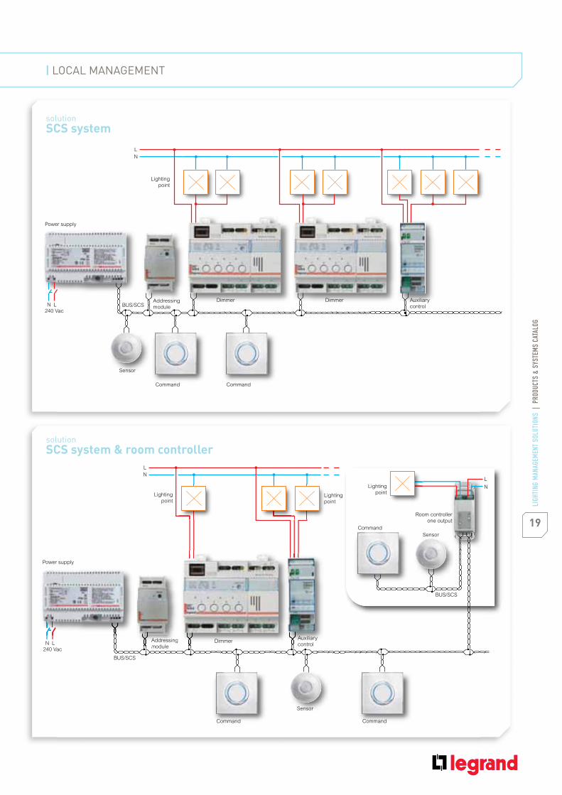
solution SCS system
solution SCS system & room controller
Room controller
one output
Lighting
pointLighting
point
Lighting
point
Addressing
moduleDimmer
Auxiliary
control
L
N
LN
L
N
Command Command
Command
Sensor
BUS/SCS
BUS/SCS
240 Vac
Power supply
Sensor
Addressing
module
Auxiliary
controlDimmer
Lighting
point
Addressing
module
Dimmer Auxiliary
control
DimmerLN
L
N
Command Command
BUS/SCS240 Vac
Power supply
Sensor
19LI
GHTI
NG M
ANAG
EMEN
T SO
LUTI
ONS
| P
RODU
CTS
& SY
STEM
S CA
TALO
G
| LOCAL MANAGEMENT

description of centralised management
Installation solution for an office building with 3 floors
description of centralised management
Installation solution for an office building with 3 floors
240 Vac12 V
240 Vac
240 Vac
Power supplyControl unit n
n Floor
2nd Floor
1rst Floor
BUS Ethernet
BUS/SCS
BUS/SCS
BUS/SCS
12 V
Control unit 2
12 V
Control unit 1
Power supply
Power supply
Addressing
module
Addressing
module
20
LIGH
TING
MAN
AGEM
ENT
SOLU
TION
S |
PRO
DUCT
S &
SYST
EMS
CATA
LOG
LIGHTING MANAGEMENT PRODUCTS & SYSTEMS | BUS/SCS SYSTEMS

Command
BUS/SCS BUS/SCS
BUS/SCS BUS/SCS
Command
Command Command
Command
Command Command
Zone 1 Zone 2
Zone 3 Zone n
Room controller
one output
Room controller
one output
Room controller
one output
Room controller
one outputSensor
Sensor
Sensor
Sensor
Sensor
Sensor
SensorSensor
Dimmer
Dimmer
Auxiliary
control
Auxiliary
control
Lighting
point
Lighting
point
Lighting
point
Lighting
point
Lighting
pointLighting
point
Lighting
point
Lighting
point
L
N240 Vac
L
N240 Vac
Zone 1 Zone 2L
N240 Vac
L
N240 Vac
L
N240 Vac
Zone 3 Zone nL
N240 Vac
DimmerD
p
DimmerD
p
Au
co
p
Au
co
p
21LI
GHTI
NG M
ANAG
EMEN
T SO
LUTI
ONS
| P
RODU
CTS
& SY
STEM
S CA
TALO
G
| CENTRALISED MANAGEMENT

22
LIGH
TING
MAN
AGEM
ENT
SOLU
TION
S |
PRO
DUCT
S &
SYST
EMS
CATA
LOG
LIGHTING MANAGEMENT PRODUCTS & SYSTEMS | COMMISSIONING
Configuration tools
Legrand offers three types of configuration for connecting
our products to the BUS/SCS line:
Plug n’ goAt initial installation, the room
controller recognises the control
which is directly connected to
the input and sets its outputs
accordingly. It can remain at this
initial setup configuration, or it can
be modified.
1
Push n’ learnThe Push and Learn method is used
to change or to adapt the default
configuration between the control
and the room controller.
2

23LI
GHTI
NG M
ANAG
EMEN
T SO
LUTI
ONS
| P
RODU
CTS
& SY
STEM
S CA
TALO
G
Lighting Management SuiteWith the Lighting Management
Suite, all configuration work is
carried out using the software,
in OFFLINE mode, and then
downloaded to the installation.
Any modification and tuning can be
carried out directly on or off-site.
3

24
LIGH
TING
MAN
AGEM
ENT
SOLU
TION
S |
PRO
DUCT
S &
SYST
EMS
CATA
LOG
LIGHTING MANAGEMENT PRODUCTS & SYSTEMS | SOFTWARE SUITE
Software suite
With the Lighting Management Suite, all configuration work is
carried out using the software
Pre-salesThe LIGHTING PAYBACK software
is used for quick, easy calculation
of the benefits of the lighting
management strategies chosen
for a given project, evaluating
the energy consumption and the
economic return on the investment.
This software can be downloaded
free of charge. It is not part of the
‘Legrand Lighting Management
Suite’.
1
ProjectWith YouPROJECT you can quickly
obtain economic costings for a
project, determining the list of
equipment, its price and all the
installation costs. Once the project
has been validated, it can be used
as a basis for designing the working
documents.
YouPROJECT is part of the ‘Legrand
Lighting Management Suite’.
2
Design | InstallationThe YouPROJECT software can
be used with SPAC or AUTOCAD
to create the whole installation
design, from the wiring to
addressing the products, right
through to the initial OFFLINE
configuration of the devices. An
installation drawing can be printed
out and given to the user.
3
25LI
GHTI
NG M
ANAG
EMEN
T SO
LUTI
ONS
| P
RODU
CTS
& SY
STEM
S CA
TALO
G
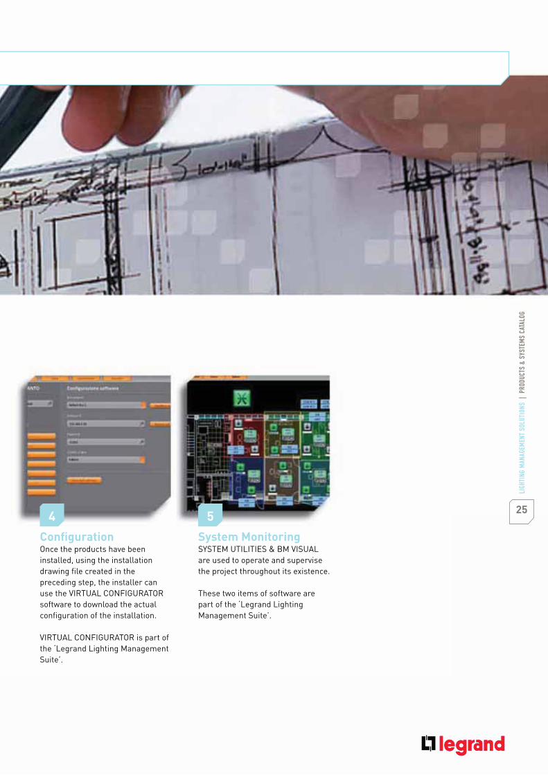
Configuration Once the products have been
installed, using the installation
drawing file created in the
preceding step, the installer can
use the VIRTUAL CONFIGURATOR
software to download the actual
configuration of the installation.
VIRTUAL CONFIGURATOR is part of
the ‘Legrand Lighting Management
Suite’.
4
System Monitoring SYSTEM UTILITIES & BM VISUAL
are used to operate and supervise
the project throughout its existence.
These two items of software are
part of the ‘Legrand Lighting
Management Suite’.
5

RELATED SERVICES
Enjoy a unique level of service From the initial design stage to the first time
an occupant enters a building, you can be sure
that Legrand will be available to help

27LI
GHTI
NG M
ANAG
EMEN
T SO
LUTI
ONS
| P
RODU
CTS
& SY
STEM
S CA
TALO
G
Local supportOur sales representatives are available to assist with all
aspects of lighting management projects. Services include
building walk-through, training, payback analysis reports
and product demonstrations.
Ranging from technical support and free design services, to field services for
commissioning, our team of experts is available to assist you with all your
lighting management requirements. With our team, you can be confident that
your lighting management project will provide optimum performance and
comply with any guidelines required for code compliance or sustainability.
Technical supportTelephone technical support from our dedicated
team offers personal guidance for application-related
questions, installation assistance or troubleshooting.

CATALOGUE
Switch sensors
BUS/SCS system
Our range provides you with
the most appropriate
solutions

29LI
GHTI
NG M
ANAG
EMEN
T SO
LUTI
ONS
| P
RODU
CTS
& SY
STEM
S CA
TALO
G
Controls P35
Room controllers
(2 outputs) P32
Switch sensors
(1 output) P30
Radio & ZigBee®
accessories P43
SCS sensors P36
Room controllers P38
Software
& accessories P42
Dimmers & actuators P40
30
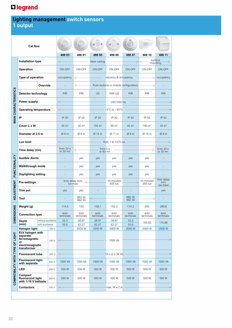
lighting management switch sensors1 output
Cat.Nos
488 03 488 01 488 05 488 06 488 07 488 10 488 11
MA
IN C
HA
RA
CT
ER
IST
ICS
Installation type
Operation ON-OFF ON-OFF ON-OFF ON-OFF ON-OFF ON-OFF ON-OFF
Type of operation occupancy vacancy & occupancy occupancy
Override - -
Detector technology PIR PIR US PIR/ US PIR PIR PIR
Power supply
Operating temperature -5°C to +45°C
IP IP 20 IP 20 IP 20 IP 20 IP 20 IP 55 IP 42
Cover L x W 45 m2 45 m2 150 m2 90 m2 45 m2 180 m2 45 m2
Diameter at 2.5 m Ø 8 m Ø 8 m Ø 14 m Ø 11 m Ø 8 m Ø 15 m Ø 8 m
Lux level from 1 to 1275 lux
Time delay (mn)from 20 sto 30 mn
FU
NC
TIO
NA
LIT
Y
Audible Alerts - yes yes yes yes yes -
Walkthrough mode - yes yes yes yes yes -
Daylighting setting - yes yes yes yes yes -
AD
JU
ST
ME
NT Pre-settings
time delay mini, lux maxi
15 minutes 500 lux
15 minutes300 lux
time delay mini
lux maxi
Trim pot yes yes - - - - yes
Tool - -
DIM
EN
SIO
NS Weight (g) 114.5 150 159.1 162.2 114.2 205 266.6
Connection typeauto
terminalsauto
terminalsauto
terminalsauto
terminalsauto
terminalsauto
terminalsauto
terminals
Depth(mm)
without auxiliaries 52.3 58.97 58.97 58.97 52.3165.83 115.86
with auxiliaries 55.6 62.27 62.27 62.27 55.6
CO
MP
AT
IBIL
ITY
WIT
H T
YP
E O
F L
IGH
T
Halogen light - 2500 W 2000 W 2000 W 2000 W 2000 W 2000 W
ELV halogen with separate ferromagneticor electromagnetic transformer
1000 VA
Fluorescent tube 10 x (2 x 36 W)
Fluorescent light with separate
1000 VA 1000 VA 1000 VA 1000 VA 1000 VA 1000 VA 1000 VA
LED 500 W 500 W 500 W 500 W 500 W 500 W 500 W
Compact fluorescent light with 1-10 V ballasts
500 W 500 W 500 W 500 W 500 W 500 W 500 W
Contactors max. W 2 A
false ceilingsurface
mounting
Push-buttons or mobile configurators
240 V/60 Hz
from 0 sto 60 mn
from 20 sto 30 mn
882 35 882 30
882 35 882 30
240 V
240 V
240 V
240 V
240 V
240 V
240 V
31
lighting management switch sensors1 output
488 72 488 68488 07 RJ 45 connectors882 30882 35
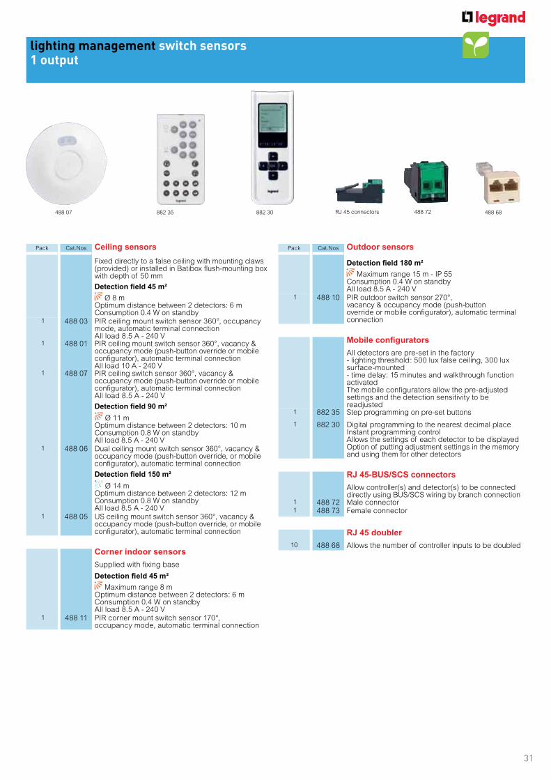
Pack Cat.Nos Ceiling sensors
Fixed directly to a false ceiling with mounting claws (provided) or installed in Batibox flush-mounting box with depth of 50 mm
Detection field 45 m²
Ø 8 m Optimum distance between 2 detectors: 6 m Consumption 0.4 W on standby
1 488 03 PIR ceiling mount switch sensor 360°, occupancy mode, automatic terminal connection All load 8.5 A - 240 V
1 488 01 PIR ceiling mount switch sensor 360°, vacancy & occupancy mode (push-button override or mobile configurator), automatic terminal connection All load 10 A - 240 V
1 488 07 PIR ceiling switch sensor 360°, vacancy & occupancy mode (push-button override or mobile configurator), automatic terminal connection All load 8.5 A - 240 V
Detection field 90 m²
Ø 11 m Optimum distance between 2 detectors: 10 m Consumption 0.8 W on standby All load 8.5 A - 240 V
1 488 06 Dual ceiling mount switch sensor 360°, vacancy & occupancy mode (push-button override, or mobile configurator), automatic terminal connection
Detection field 150 m²
Ø 14 m Optimum distance between 2 detectors: 12 m Consumption 0.8 W on standby All load 8.5 A - 240 V
1 488 05 US ceiling mount switch sensor 360°, vacancy & occupancy mode (push-button override, or mobile configurator), automatic terminal connection
Corner indoor sensors
Supplied with fixing base
Detection field 45 m²
Maximum range 8 mOptimum distance between 2 detectors: 6 mConsumption 0.4 W on standby All load 8.5 A - 240 V
1 488 11 PIR corner mount switch sensor 170°, occupancy mode, automatic terminal connection
Pack Cat.Nos Outdoor sensors
Detection field 180 m²
Maximum range 15 m - IP 55Consumption 0.4 W on standby All load 8.5 A - 240 V
1 488 10 PIR outdoor switch sensor 270°, vacancy & occupancy mode (push-button override or mobile configurator), automatic terminal connection
Mobile configurators
All detectors are pre-set in the factory- lighting threshold: 500 lux false ceiling, 300 lux surface-mounted- time delay: 15 minutes and walkthrough function activatedThe mobile configurators allow the pre-adjusted settings and the detection sensitivity to be readjusted
1 882 35 Step programming on pre-set buttons
1 882 30 Digital programming to the nearest decimal place Instant programming control Allows the settings of each detector to be displayed Option of putting adjustment settings in the memory and using them for other detectors
RJ 45-BUS/SCS connectors
Allow controller(s) and detector(s) to be connected directly using BUS/SCS wiring by branch connection
1 488 72 Male connector 1 488 73 Female connector
RJ 45 doubler
10 488 68 Allows the number of controller inputs to be doubled

32
lighting management room controller2 outputs
Cat.Nos
488 50(1) 488 20 488 21 488 22 488 23 488 24 488 30
MA
IN C
HA
RA
CT
ER
IST
ICS
Installation typefalse ceiling
cable ductingfalse ceiling surface-mounting
Operation ON-OFF ON-OFF ON-OFF ON-OFF ON-OFF ON-OFF ON-OFF
Type of operation - vacancy & occupancy
Override - Push-buttons, or IR remote
Detector technology - PIR US PIR/US PIR/US PIR PIR
Power supply 240 V 27 V powered by 488 50
Operating temperature -5 °C to +45 °C
IP IP 20 IP 20 IP 20 IP 20 IP 42 IP 42 IP 55
Cover L x W - 45 m2 150 m2 90 m2 90 m2 45 m2 180 m2
Diameter at 2.5 m - Ø 8 m Ø 14 m Ø 11 m Ø 11 m Ø 8 m Ø 15 m
Lux level - from 1 to 1275 lux
Time delay (mn) - from 0 to 255 h
FU
NC
TIO
NA
LIT
Y
Audible Alerts - yes yes yes yes yes yes
Walkthrough mode - yes yes yes yes yes yes
Daylight setting - yes yes yes yes yes yes
AD
JU
ST
ME
NT
Pre-settings - 15 minutes / 500 lux 15 minutes / 300 lux
Trim pot - - - - - - -
Tool - 882 30 & 882 35 and software
DIM
EN
SIO
NS
Weight (g) 272 95.5 143.1 147.8 241.7 237.5 205
Dimensions L x W x H (mm) 190 x 70 x 51 55 X Ø 102 55 X Ø 102 55 X Ø 102 105 x 70 x 70 105 x 70 x 70 166 X 81 X 104
Connection type screw terminals RJ 45 RJ 45 RJ 45 RJ 45 RJ 45 RJ 45
Flush-mounted depth (mm) - 50
CO
MP
AT
IBIL
ITY
WIT
H T
YP
E O
F L
IGH
T
Halogen light 3600 W - - - - - -
ELV halogen with separate ferromagneticor electromagnetic transformer
1800 VA - - - - - -
Fluorescent tube 1800 VA - - - - - -
Fluorescent light with separate ferromagnetic or electronic ballast
500 W - - - - - -
LED 500 W - - - - - -
Compact fluorescent light with 1-10 V ballasts
1800 VA - - - - - -
Contactors relay output - - - - - -
(1) to be associated with Cat.Nos 488 20/21/22/23/24/30
240 V
240 V
240 V
240 V
240 V
240 V
240 V
}

33
lighting management room controller2 outputs
488 50 488 20 488 22 488 23
(directional head)
Pack Cat.Nos Room controller
Allows 2 lighting circuits to be controlled in 2 different phases or 1 lighting circuit and 1 A/C circuit Ability to connect the detector(s) and push-button(s) on each circuit Fixed directly to the false ceiling via cable ducting Controller/detector output connection (up to 10 detectors Cat.Nos 488 20/21/22/30/24/23) by cord or RJ 45 cable (please refer to Legrand general catalogue) or BUS/SCS cable to be fitted with RJ 45 connector Cat.No 488 72 (p. 31) Power supply 100/240 V
1 488 50 Room controller 2 inputs 2 outputs 16 A
Ceiling SCS sensors
Fixed directly to the false ceiling with mounting claws(supplied) or installed in deep Batibox boxes with depth of 50 mm Connect to 2 circuit controller Cat.No 488 50 by cord or RJ 45 cable or BUS/SCS cable fitted with RJ 45 connector Cat.No 488 72 (p. 31)
Detection field 45 m²
Ø 8 mOptimum distance between 2 detectors: 6 m Consumption 0.2 W on standby All load 10 A - 240 V
1 488 20 PIR ceiling mount switch sensor 360°, vacancy & occupancy mode (push-button override, or IR remote), RJ 45 connection
Detection field 90 m²
Ø 11 m Optimum distance between 2 detectors: 10 m Consumption 0.5 W on standby All load 10 A - 240 V
1 488 22 DUAL corner mount SCS sensor 360°, vacancy & occupancy mode (push-button override, or IR remote), RJ 45 connection
Detection field 150 m²
Ø 14 m Optimum distance between 2 detectors: 12 m Consumption 0.5 W on standby All load 10 A - 240 V
1 488 21 US ceiling mount SCS sensor 360°, vacancy & occupancy mode (push-button override, or IR remote), RJ 45 connection
Pack Cat.Nos Corner SCS sensors
Supplied with fixing base Connect to 2 circuit controller Cat.No 488 50 by cord or RJ 45 cable or BUS/SCS cable fitted with RJ 45 connector Cat.No 488 72 (p. 31)
Detection field 45 m²
Maximum range 8 m - IP 42 Optimum distance between 2 detectors: 6 m Consumption 0.2 W on standby All load 10 A - 240 V
1 488 24 PIR corner mount switch sensor 180°, vacancy & occupancy mode (push-button override, or IR remote), RJ 45 connection
Detection field 90 m²
Maximum range 11 m - IP 42With directional head Optimum distance between 2 detectors: 10 m Consumption 0.2 W on standby All load 10 A - 240 V
1 488 23 DUAL corner mount SCS sensor 180°, vacancy & occupancy mode (push-button override, or IR remote), RJ 45 connection
Detection field 180 m²
Maximum range 15 m - IP 55Consumption 0.5 W on standby All load 10 A - 240 V
1 488 30 PIR corner mount SCS sensor 270°, vacancy & occupancy mode (push-button override, or IR remote), RJ 45 connection

34
Lighting management technologies
■ Wall mounting
Wall mount sensors have a mounting base. For easy and quick mounting the base has to be fixed against the wall,the wires connected to the automatic wiring block. Then the sensor part is fitted onto the base.
■ Ceiling mounting
All sensors have built-in bracket systems that enable ceiling mounting. Most sensors are suitable for standard EU boxes (diam 65) Cat No 80051. This is important for applications where the ceiling is unavailable for sensor installation. Only one Cat.No for two ways of mounting.
For advanced configuration:
For standard configuration:
Cat.No 882 35
Cat.No 882 30
- Time level: 3, 5, 10, 15, 20 mn- Lux level: 20, 100, 300, 500, 1000 lux- Occupancy, occupancy walkthrough, vacancy, modes - PIR & US detection sensibility: low, medium, high, very high- test mode
This commissioning tool enables a very precise commissioning of your sensors.- Time: from 0 seconds to 60 mn- Lux: from 1 lux to 1275 lux- Detection mode: occupancy, occupancy walkthrough, vacancy modes- PIR & US detection sensibility: low, medium, high, very high- It also provides access to advanced functions such as calibration, alarms, choice of mode of detection (initial detection, maintain detection, retrigger), daylight function - It also allows downloading of sensor parameters, saving of these parameters in folders and their duplication
Two commissioning tools can be used to adjust settings:
■ Settings
Most sensors feature Smart Factory Set technology, adjustments are typically not needed after installation.If adjustments need to be made (due to last minute changes in furniture or fixture placement), sensitivity and time delays should match the activity levels of the monitored spaces.
■ Room controller (2 outputs)
The room controller is a key component of the lighting control system. It provides low voltage power to SCS sensors.Several sensors, can be linked (up to 10). Only one Cat.No for several applications.
488 20
572030/2530
572030/2530
488 22 488 21
48850
Product features> Screw terminal block> Auxiliary input for manual control by simple push (48850 only)> 1 RJ 45 input for SCS sensors> 16 A outputs for lighting and FAN
* For support frames and cover plates refer to Arteor Catalogue.

35
lighting management BUS/SCS systemcontrols
Individual or centralised controls for lighting managementSupplied with BUS/SCS connector Cat.No 492 22 (p. 42) for connection with the BUS/SCS cable with branch connection
- to the fixed ceiling controller via BUS/SCS cable fitted with connector Cat.No 488 72 (p. 37)- directly to the BUS/SCS cable in the event of a modular controller control unit
Pack Cat.Nos "Push-button type" lighting control units
Used to control 1 controllerArteor
1 5739 87 Arteor mechanism
"Switch type" multifunctional control units
For controlling a group of controllers: ON/OFF, dimming, ventilation, rolling blinds
Arteor1 5739 74 Arteor mechanism
Pack Cat.Nos Scenario management
Allows several controllers to be operated
4 scenarios4 buttons allowing 1 scenario to managed per buttonExample: lighting level adjustment, lighting control with openings...
Arteor1 5739 02 White1 5739 03 Magnesium
Multiple scenarios
Touch-screen control Allows manual or programmed control of lighting (lighting level), openings, fans and multimedia equipment
1 5739 60 Equipped with White and Magnesium surroundTo be installed in flush-mounting box Cat.Nos 892 79 or 893 79 To be fitted with plates Cat.Nos 5764 84 Mirror White, 5764 83 Mirror Black, 5764 86 Stainless Steel, 5764 80 Gold Brass and 5764 87 Woven Metal
784 73
For support frames, cover plates
and wall boxes, refer to
Legrand Catalogue or contact
your local office.
5739 60

36
lighting management BUS/SCS systemSCS sensors
Cat.Nos
488 20 488 21 488 22 488 23 488 24 488 30
MA
IN C
HA
RA
CT
ER
IST
ICS
Installation type false ceiling surface mounting
Operation ON-OFF & dimming + adjust
Type of operation vacancy & occupancy
Override Push-buttons, mobile configurators or software
Detector technology PIR US PIR/US PIR/US PIR PIR
Power supply 27 V powered by BUS/SCS or room controllers
Operating temperature -5°C to +45°C
IP IP 20 IP 20 IP 20 IP 42 IP 42 IP 55
Cover L x W 45 m2 150 m2 90 m2 90 m2 45 m2 180 m2
Diameter at 2.5 m Ø 8 m Ø 14 m Ø 11 m Ø 11 m Ø 8 m Ø 15 m
Lux level from 1 to 1275 lux
Time delay (mn) from 0 to 255 h
FU
NC
TIO
NA
LIT
Y
Audible Alerts yes yes yes yes yes yes
Walkthrough mode yes yes yes yes yes yes
Daylight setting yes yes yes yes yes yes
AD
JU
ST
ME
NT Pre-settings 15 minutes / 500 lux 15 minutes / 300 lux
Trim pot - - - - - -
Tool 882 30 and 822 35 and software
DIM
EN
SIO
NS Weight (g) 95.5 143.1 147.8 241.7 237.5 205
Connection type RJ 45 RJ 45 RJ 45 RJ 45 RJ 45 RJ 45
Flush-mounted depth (mm) 50 50 50 50 50 50
37
lighting management BUS/SCS systemSCS sensors
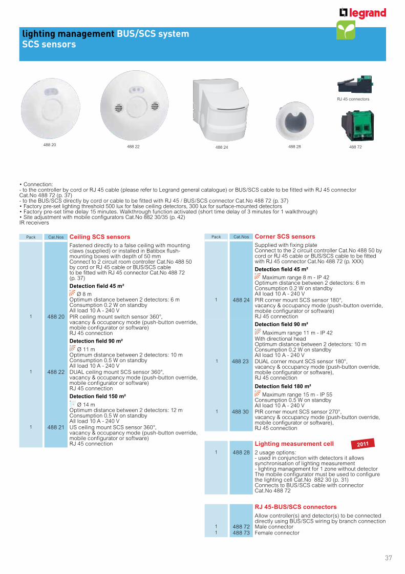
- to the controller by cord or RJ 45 cable (please refer to Legrand general catalogue) or BUS/SCS cable to be fitted with RJ 45 connectorCat.No 488 72 (p. 37) - to the BUS/SCS directly by cord or cable to be fitted with RJ 45 / BUS/SCS connector Cat.No 488 72 (p. 37)
IR receivers
Pack Cat.Nos Ceiling SCS sensors
Fastened directly to a false ceiling with mounting claws (supplied) or installed in Batibox flush-mounting boxes with depth of 50 mm Connect to 2 circuit room controller Cat.No 488 50 by cord or RJ 45 cable or BUS/SCS cable to be fitted with RJ 45 connector Cat.No 488 72 (p. 37)
Detection field 45 m²
Ø 8 mOptimum distance between 2 detectors: 6 mConsumption 0.2 W on standbyAll load 10 A - 240 V
1 488 20 PIR ceiling mount switch sensor 360°,vacancy & occupancy mode (push-button override, mobile configurator or software) RJ 45 connection
Detection field 90 m²
Ø 11 mOptimum distance between 2 detectors: 10 mConsumption 0.5 W on standbyAll load 10 A - 240 V
1 488 22 DUAL ceiling mount SCS sensor 360°,vacancy & occupancy mode (push-button override, mobile configurator or software) RJ 45 connection
Detection field 150 m²
Ø 14 mOptimum distance between 2 detectors: 12 mConsumption 0.5 W on standbyAll load 10 A - 240 V
1 488 21 US ceiling mount SCS sensor 360°,vacancy & occupancy mode (push-button override, mobile configurator or software) RJ 45 connection
Pack Cat.Nos Corner SCS sensors
Supplied with fixing plate Connect to the 2 circuit controller Cat.No 488 50 by cord or RJ 45 cable or BUS/SCS cable to be fitted with RJ 45 connector Cat.No 488 72 (p. XXX)
Detection field 45 m²
Maximum range 8 m - IP 42Optimum distance between 2 detectors: 6 mConsumption 0.2 W on standbyAll load 10 A - 240 V
1 488 24 PIR corner mount SCS sensor 180°,vacancy & occupancy mode (push-button override, mobile configurator or software) RJ 45 connection
Detection field 90 m²
Maximum range 11 m - IP 42With directional head Optimum distance between 2 detectors: 10 m Consumption 0.2 W on standby All load 10 A - 240 V
1 488 23 DUAL corner mount SCS sensor 180°, vacancy & occupancy mode (push-button override, mobile configurator or software), RJ 45 connection
Detection field 180 m²
Maximum range 15 m - IP 55 Consumption 0.5 W on standby All load 10 A - 240 V
1 488 30 PIR corner mount SCS sensor 270°, vacancy & occupancy mode (push-button override, mobile configurator or software), RJ 45 connection
Lighting measurement cell
1 488 28 2 usage options: - used in conjunction with detectors it allows synchronisation of lighting measurement - lighting management for 1 zone without detectorThe mobile configurator must be used to configure the lighting cell Cat.No 882 30 (p. 31) Connects to BUS/SCS cable with connector Cat.No 488 72
RJ 45-BUS/SCS connectors
Allow controller(s) and detector(s) to be connected directly using BUS/SCS wiring by branch connection
1 488 72 Male connector1 488 73 Female connector
488 20488 72488 22 488 24 488 28
RJ 45 connectors
2011

38
lighting management BUS/SCS systemroom controllers
Cat.Nos
488 40 488 41 488 42 488 43 488 44 488 45 488 47
MA
IN C
HA
RA
CT
ER
IST
ICS
Installation type fixed false ceiling and cable ducting
Type of operation ON-OFF dimmingON-OFF dimming
+ automation
Number of outputs 1 2 2 4 4 22 lighting +
2 automation
Power supply 240 V
Operating temperature -5°C to +45°C
IP IP 20 IP 20 IP 20 IP 20 IP 20 IP 20 IP 20
Dimensions (mm)L x W x H
207 x 71 x 48 207 x 71 x 48 207 x 97 x 48 257 x 148 x 51 257 x 148 x 51 257 x 148 x 51 257 x 148 x 51
Weight (g.) 255 265 337 380 424 458 430
Connection type screw terminals screw terminals screw terminals screw terminals screw terminals screw terminals screw terminals
CO
MP
AT
IBIL
ITY
WIT
H T
YP
E O
F L
IGH
T
Halogen light 3600 W 3600 W 3600 W 3600 W - 2000 W 3600 W
ELV halogen with separate ferromagnetic or electromagnetic transformer
3600 W 3600 W 3600 W 3600 W - 2000 VA 3600 VA
Fluorescent tube 1 x 1000 VA 2 x 1000 VA 2 x 1000 VA 4 x 1000 VA - - 2 x 1000 W
Fluorescent light with separate ferromagnetic or electronic ballast
1 x 1000 VA 2 x 1000 VA 2 x 1000 VA 4 x 1000 VA - - 2 x 1000 VA
LED 1 x 500 W 2 x 500 W - 4 x 500 W - - 2 x 500 W
Compact fluorescent light with 1-10 V ballasts
1 x 1000 VA 2 x 1000 VA 2 x 1000 VA 4 x 1000 VA - - 2 x 1000 VA
DALI Ballast - - - - 4 x 16 ballasts - -
Motors - - - - - - 500 VA
240 V
240 V
240 V
240 V
240 V
240 V
2011
39
lighting management BUS/SCS systemroom controllers
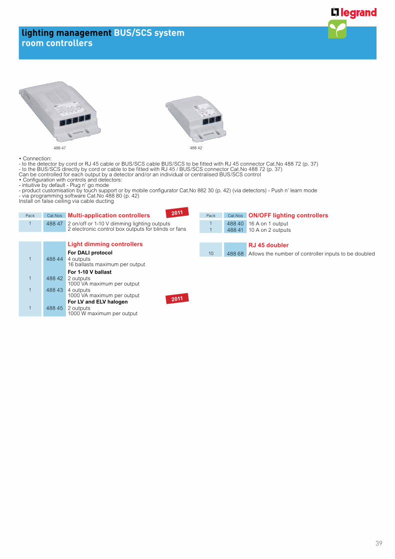
- to the detector by cord or RJ 45 cable or BUS/SCS cable BUS/SCS to be fitted with RJ 45 connector Cat.No 488 72 (p. 37) - to the BUS/SCS directly by cord or cable to be fitted with RJ 45 / BUS/SCS connector Cat.No 488 72 (p. 37)Can be controlled for each output by a detector and/or an individual or centralised BUS/SCS control
- intuitive by default - Plug n’ go mode- product customisation by touch support or by mobile configurator Cat.No 882 30 (p. 42) (via detectors) - Push n’ learn mode- via programming software Cat.No 488 80 (p. 42) Install on false ceiling via cable ducting
Pack Cat.Nos Multi-application controllers
1 488 47 2 on/off or 1-10 V dimming lighting outputs 2 electronic control box outputs for blinds or fans
Light dimming controllers
For DALI protocol1 488 44 4 outputs
16 ballasts maximum per output
For 1-10 V ballast1 488 42 2 outputs
1000 VA maximum per output1 488 43 4 outputs
1000 VA maximum per outputFor LV and ELV halogen
1 488 45 2 outputs 1000 W maximum per output
Pack Cat.Nos ON/OFF lighting controllers
1 488 40 16 A on 1 output1 488 41 10 A on 2 outputs
RJ 45 doubler
10 488 68 Allows the number of controller inputs to be doubled
488 47 488 42
2011
2011
40
lighting management BUS/SCS systemdimming and actuators
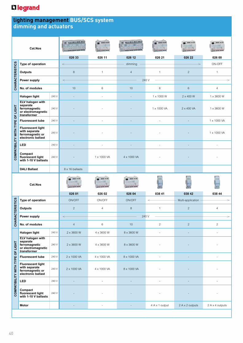
Cat.Nos
026 33 026 11 026 12 026 21 026 22 026 00
CH
AR
AC
TE
RIS
TIC
S
Type of operation dimming ON-OFF
Outputs 8 1 4 1 2 1
Power supply 240 V
No. of modules 10 6 10 6 6 4
CO
MP
AT
IBIL
ITY
WIT
H T
YP
E O
F L
IGH
T
Halogen light - - - 1 x 1000 W 2 x 400 W 1 x 3600 W
ELV halogen with separate ferromagneticor electromagnetic transformer
- - - 1 x 1000 VA 2 x 400 VA 1 x 3600 W
Fluorescent tube - - - - - 1 x 1000 VA
Fluorescent light with separate ferromagnetic or electronic ballast
- - - - - 1 x 1000 VA
LED - - - - - -
Compact fluorescent light with 1-10 V ballasts
- 1 x 1000 VA 4 x 1000 VA - - -
DALI Ballast 8 x 16 ballasts
Cat.Nos
026 01 026 02 026 04 038 41 038 42 038 44
CH
AR
AC
TE
RIS
TIC
S
Type of operation ON/OFF ON/OFF ON/OFF Multi-application
Outputs 2 4 8 1 2 4
Power supply 240 V
No. of modules 4 6 10 2 2 2
CO
MP
AT
IBIL
ITY
WIT
H T
YP
E O
F L
IGH
T
Halogen light 2 x 3600 W 4 x 3600 W 8 x 3600 W - - -
ELV halogen with separate ferromagneticor electromagnetic transformer
2 x 3600 W 4 x 3600 W 8 x 3600 W - - -
Fluorescent tube 2 x 1000 VA 4 x 1000 VA 8 x 1000 VA - - -
Fluorescent light with separate ferromagnetic or electronic ballast
2 x 1000 VA 4 x 1000 VA 8 x 1000 VA - - -
LED - - - - - -
Compact fluorescent light with 1-10 V ballasts
- - - - - -
Motor - - - 4 A x 1 output 2 A x 2 outputs 2 A x 4 outputs
240 V
240 V
240 V
240 V
240 V
240 V
240 V
240 V
240 V
240 V
240 V
240 V

41
lighting management BUS/SCS systemdimming and actuators
Modular controllers and interfaces connected to the BUS/SCS by BUS/SCS cable. Each output is independent and can be used in conjunction with a controlConfiguration with controls and detectors: - intuitive with Cat.No 035 70 (addressing module) - product customisation by touch support - through programming software Cat.No 488 80 (p. 42)
Pack Cat.Nos Konnex - BUS/SCS IP interface
1 5739 93 Requires power supply unit Cat.No 035 64To be connected to zone management unit Cat.No 026 45For operation requires software pack Cat.No 488 81 or supervision requires Cat.No 488 82 (p. 42)6 x 17.5 mm DIN modules
Zone management unit
1 026 45 Includes 2 functions:- manages scenario programming (e.g. time management, lighting, presence)- IP interface, links the BUS/SCS infrastructure and the IP networkRequires power supply unit Cat.No 035 64For operation requires software pack Cat.No 488 81 or supervision requires Cat.No 488 82 (p. 42)6 x 17.5 mm DIN modules
Extension gateways
Allow the BUS/SCS to communicate with other systems
Scenario module1 035 51 Allows scenarios to be created through link with
Arteor Cat.No 5739 60 without a software tool
Konnex - BUS/SCS1 035 63 Allows the on/off signal to travel between a Konnex
installation and the BUC/SCS installation 2 x 17.5 mm DIN modules
Wiring system - BUS/SCS1 035 53 Used to connect traditional wiring systems
(e.g. switch, timer, external sensor)2 independent contacts2 x 17.5 mm DIN modules
BUS - BUS/SCS extension
1 035 62 Used to extend a line beyond 175 products and 500 m and therefore allows product identification in the same lineNeeds a power supply Cat.Nos 035 60/662 x 17.5 mm DIN modules
Modular power supply units
For BUS/SCS1 035 60 240 VA - 27 Vac - 1.2 A
8 x 17.5 mm DIN modules1 035 67 240 VA - 27 Vac - 500 mA
2 x 17.5 mm DIN modulesFor Cat.Nos 5739 93 and 026 45
1 035 64 240 VA - 12 Vac - 1.2 A6 x 17.5 mm DIN modules
Pack Cat.Nos Dimming controllers
For DALI protocol
10 x 17.5 mm DIN modules1 026 33 8 outputs
16 ballasts maximum per output, frame steering
For 1-10 V ballast1 026 11 1 output - 1000 VA maximum
6 x 17.5 mm DIN modules1 026 12 4 outputs - 1000 VA maximum per output
10 x 17.5 mm DIN modules
For LV and ELV halogen
6 x 17.5 mm DIN modules1 026 21 1 output - 1000 W maximum1 026 22 2 outputs - 500 W maximum per output
ON/OFF lighting controllers
1 026 00 1 x 16 A output4 x 17.5 mm DIN modules
1 026 01 2 x 16 A outputs4 x 17.5 mm DIN modules
1 026 02 4 x 16 A outputs6 x 17.5 mm DIN modules
1 026 04 8 x 16 A outputs10 x 17.5 mm DIN modules
Multi-application controllers
NO contactFor roller blinds and motors2 x 17.5 mm DIN modules
1 038 41 1 x 16 A output1 038 42 2 x 6 A outputs1 038 44 4 x 6 A outputs
Addressing module
1 035 70 To be used with controller for touch support customisation directly on the controller and the control unit2 x 17.5 mm DIN modules
026 33 038 42 5739 93 035 62
2011
42
lighting management BUS/SCS systemsoftware
lighting management BUS/SCS systemaccessories
882 30882 35
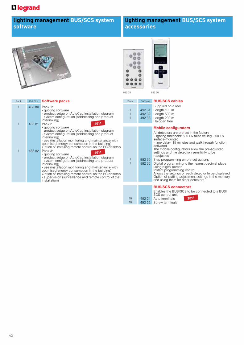
Pack Cat.Nos Software packs
1 488 80 Pack 1:- quoting software- product setup on AutoCad installation diagram- system configuration (addressing and product interlinking)
1 488 81 Pack 2- quoting software- product setup on AutoCad installation diagram- system configuration (addressing and product interlinking)- use (installation monitoring and maintenance with optimised energy consumption in the building)Option of installing remote control on the PC desktop
1 488 82 Pack 3: - quoting software- product setup on AutoCad installation diagram- system configuration (addressing and product interlinking) - use (installation monitoring and maintenance with optimised energy consumption in the building)Option of installing remote control on the PC desktop- supervision (surveillance and remote control of the installation)
Pack Cat.Nos BUS/SCS cables
Supplied on a reel1 492 31 Length 100 m1 492 32 Length 500 m1 492 33 Length 200 m
Halogen free
Mobile configurators
All detectors are pre-set in the factory - lighting threshold: 500 lux false ceiling, 300 lux surface-mounted - time delay: 15 minutes and walkthrough function activated The mobile configurators allow the pre-adjusted settings and the detection sensitivity to be readjusted
1 882 35 Step programming on pre-set buttons1 882 30 Digital programming to the nearest decimal place
using digital screen Instant programming control Allows the settings of each detector to be displayed Option of putting adjustment settings in the memory and using them for other detectors
BUS/SCS connectorsEnables the BUS/SCS to be connected to a BUS/SCS control unit
10 492 24 Auto terminals10 492 22 Screw terminals
2011
2011
2011
43
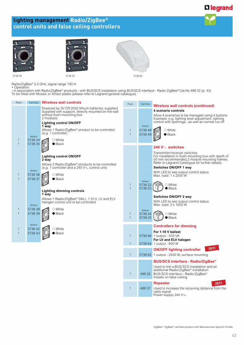
lighting management Radio/ZigBee®
control units and false ceiling controllers
Radio/ZigBee® 2.4 GHz, signal range 100 m
- in association with Radio/ZigBee® products - with BUS/SCS installation using BUS/SCS interface - Radio ZigBee® Cat.No 488 32 (p. 43)To be fitted with Mosaic or Arteor plates (please refer to Legrand general catalogue)
5738 625738 49 5738 35
Pack Cat.Nos Wireless wall controls
Powered by 3V CR 2032 lithium batteries, suppliedSupplied with support, directly mounted on the wall without flush-mounting box2 modules
Lighting control ON/OFF 1 wayAllows 1 Radio/ZigBee® product to be controlled (e.g. 1 controller)
Arteor
1 5738 34 White1 5738 35 Black
Lighting control ON/OFF 2 way
Allows 2 Radio/ZigBee® products to be controlled (e.g. 1 controller and a 240 VA control unit)
Arteor
1 5738 36 White
1 5738 37 Black
Lighting dimming controls 1 way
Allows 1 Radio/ZigBee® DALI, 1-10 V, LV and ELV halogen control unit to be controlled
Arteor
1 5738 38 White
1 5738 39 Black
Arteor
1 5738 42 White
1 5738 43 Black
ZigBee®: ZigBee® certified product with Manufacturer Specific Profile
Pack Cat.NosWireless wall controls (continued)
4 scenario controls
Allow 4 scenarios to be managed using 4 buttonsExample: e.g. lighting level adjustment, lighting control with openings...as well as normal cut off
Arteor
1 5738 48 White
1 5738 49 Black
240 VA switches
Transmitter/receiver switchesFor installation in flush-mounting box with depth of 50 mm recommended,2 module mounting frames.Refer to Legrand Catalogue for further details.
Switches ON/OFF 1 way
With LED to see output control statusMax. load: 1 x 2500 W
Arteor
1 5738 22 White1 5738 23 Black
Switches ON/OFF 2 way
With LED to see output control statusMax. load: 2 x 1000 W
Arteor
1 5738 24 White1 5738 25 Black
Controllers for dimming
For 1-10 V ballast1 5738 66 1 output - 500 VA
For LV and ELV halogen1 5738 64 1 output - 600 W
ON/OFF lighting controller
1 5738 62 1 output - 2500 W, surface mounting
BUS/SCS interface - Radio/ZigBee®
Used to link a BUS/SCS installation and an additional Radio/ZigBee® installation
1 488 32 BUS/SCS interface - Radio/ZigBee®
Installs on false ceiling
Repeater
1 488 37 Used to increase the receiving distance from the radio signalPower supply 240 VA
2011
2011

44
lighting management Radio/ZigBee®
detectors and remote control unitsfor example: xxxxxxxxxxxxxxxlighting management Radio/ZigBee®
detectors and remote control units
Pack Cat.Nos Infrared 240 VA detector switches
Power supply 240 VARecommended fixing height: 2.50 m
Detection field 90 m²
Ø 11 m1 488 35 Dual ceiling mount detector 360°
This dual technology allows accurate presence detection from the point where the signal given by the detector is interrupted (e.g. : hand movement on a keyboard)Fixed directly to a false ceiling with mounting claws (provided) or in Batibox flush-mounting box with depth of 50 mm (please refer to Legrand general catalogue) Optimum distance between 2 detectors: 10 m
Detection field 180 m²
Maximum range 15 m - IP 551 488 14 PIR surface mount detector 270°
Dual side detection specially adapted for long narrow areas (e.g. corridors)
Battery-powered infrared detector
Powered by two 1.5 V LR 03 alkaline batteries (supplied)Recommended fixing height: 2.50 m
Detection field 180 m²
Ø 15 m - IP 551 488 31 PIR surface mount detector 270°
Dual detection specially adapted for long narrow areas (e.g. corridors)
Remote control devices
4 scenario controls
4 buttons allowing 1 scenario to be managed per buttonExample: lighting level adjustment, lighting control with openings... in the same way as normal cut off
1 882 31 IR controlPowered by two 1.5 V LR 03 alkaline batteries (supplied)
1 882 32 IR/RF controlPowered by two 1.5 V LR 03 alkaline batteries (supplied)
488 14 882 32
■ Use case No 1: also using a BUS/SCS infrastructure
■ Use case No 2: using only Radio/ZigBee®
ZigBee®: ZigBee® certified product with Manufacturer Specific Profile
Where an office is fitted out completely in glass and the BUS/SCS cannot drop vertically, a wireless Radio/ZigBee ® control unit can be installed at the door.
Manual on-switch and an automatic cut-off will maximise energy savings. In a building renovation for example, if a large area is fitted with self-contained presence detectors but the vertical connection cannot be made with its control points, Radio/ZigBee® wireless control units will be installed
BUS/SCS infrastructure with
DALI controller-BUS/SCS
4 outputs Cat.No 488 44
Infrared detector 45 m²
Cat.No 488 20
BUS/SCS interface -
Radio/ZigBee®
Cat.No 488 32
Wireless control
Cat.No 5738 34
SourceSource
230 V
Wireless control
Cat.No 5738 34
Wireless control
Cat.No 5738 34
Detector 230 V
Detection field 180 m²
Cat.No 488 14
2011
2011
45
GLOSSARY
ADDRESSING
Process at the end of which the products in a system are indi-
vidually recognised and identified. Addressing can be carried
out in various different ways (configurator, virtual configura-
tion, automatic addressing, etc.).
ADDRESS MODULE
In Push n’ Learn addressing mode, this product is used to
assign one or more addresses to certain components in the
system so that they can communicate with one another.
This module is not essential if the installation is created using
a software tool.
ARTIFICIAL LIGHT
Light produced by electric lights.
ASTRONOMICAL CONTROL
A method of calculating dusk/sunset and dawn/sunrise times
that change with the seasons of the year, based on global
latitude/longitude position. This method can be used instead
of photocell control as a basis for on/off control of exterior
lighting.
AUDIBLE WARNING
An automated method of warning occupants of impending
lighting shut-off by sounding a tone. Sometimes referred to
as “beep warning”.
AUTO ON/OFF
A control strategy used with occupancy sensors, turning
lights on and off automatically. Off when an area is unoc-
cupied and on whenever occupancy is detected. Also called
‘occupancy mode’.
AUTOMATIC SHUTOFF
A scheduled shutdown of lighting by a lighting control system.
AUXILIARY INPUT
Connector enabling an override command to be sent to a
product.
BACKBONE
LAN (IP) used to link several branches of the SCS network to
one another via zone controllers.
BACNET
Communication protocol. BACnet, acronym for Building Auto-
mation & Control networks.
BACnet is a registered trademark owned by the ASHRAE
association.
BALLAST
Component of a luminaire that is used to control the lamp.
BI-LEVEL SWITCHING
A control strategy that focuses on switching individual lamps
within a luminaire, or groups of luminaires to achieve a
reduced, balanced lighting level.
BISTABLE RELAY
Latching contact which does not require a permanent holding
voltage.
BLINK WARNING
An automated method of warning occupants of an impending
shut-off of lighting by blinking lights. Sometimes referred to
as “flick warning”.
BMS/BAS
Building management system/building automation system.
BUS
The bus is defined by the combination of a communication
protocol and a transmission medium.
It is a means of transporting and exchanging data, informa-
tion and commands. It can be physical (cable) or non-physical
(radio or IR).
BUS TOPOLOGY
All devices are connected to a central cable, called the bus or
backbone. Bus networks are relatively inexpensive and easy
to install for small networks. Ethernet systems use a bus
topology.
CENTRAL/CENTRALIZED CONTROL
A control method where the system control is located in one
central location. Usually all control commands come from
this location and wiring connections originate at this location.
CLOSED LOOP SYSTEM
A daylighting control system that measures and uses data on
the total light level from all sources (i.e. natural and artificial
light levels) in the controlled area to adjust artificial lighting
levels.
COMMISSIONING TOOL
Device for assigning operating characteristics to the various
products in the offer.
CONFIGURATION MODE
Products have a default operating mode.
This can be adapted: thumbwheels or configuration tools or
software.
CONSTANT SETPOINT
Use of a single setpoint for daylighting controls. As daylight
increases or decreases, the control attempts to maintain this
setpoint.

46
GLOSSARY
CONTINUOUS DIMMING
Lighting control method that is capable of varying the light
output of lamps over a continuous range from maximum to
minimum output (also referred to as ‘dimming’).
CONTROL GROUP OR ZONE
See ‘zone’.
CONTROL SCENARIO
A pre-programmed control strategy usually designed for
common commercial or industrial applications.
COVERAGE PATTERN
The shape and size of an area throughout which occupancy
is detectable by a sensor. The pattern is determined by the
technology, the lens design (if applicable) and the mounting
position of the sensor.
DAISY CHAIN, OR LINEAR, TOPOLOGY
A method of wiring devices where the wire runs in a straight
line from one device to another.
DAYLIGHT
Light produced by solar radiation. This includes daylight com-
ponents such as sunlight scattered by the atmosphere, light
reflected from the ground and light reflected from interior
surfaces of a building.
DAYLIGHT FACTOR
Ratio of daylight illumination on a horizontal point indoors to
the horizontal illumination outdoors, expressed as a percen-
tage, excluding direct sunlight.
DAYLIGHTING CONTROL
A lighting control method that changes the amount of light
provided by lighting fixtures as the contribution of ambient
sunlight changes.
DEADBAND
In daylighting control, a control margin above and/or below
a fixed setpoint in which minute variations in light levels
(footcandles) will not trigger an ON or OFF response from the
daylighting controller. This prevents lamp cycling.
DEFAULT SETTING
Default product setting covering the most common uses.
DIMMING
See ‘continuous dimming’.
DISTRIBUTED CONTROL
Where control for a device is located at or near the item being
controlled. This is the opposite of centralised control. The
benefits of this approach are often better modularity, conve-
nience and reduced wiring costs.
DOPPLER PRINCIPLE
The apparent change of frequency of sound or light waves
varying with the relative velocity of the source and the
observer. This is used by ultrasonic sensors to detect
occupancy.
DOUBLE CONNECTOR
Accessory enabling two RJ45 connectors to be connected on
one input.
DRY CONTACT CLOSURE
Any pair of contacts that carry no live voltage.
DUAL TECHNOLOGY
The Legrand group has invented and patented Dual
Technology to combine the best of both PIR and Active
technologies. PIR and Active sensors provide optimum control
for many areas, as some applications can be a problem for
single technology products. Our Dual Tech sensors ensure
maximum sensitivity and coverage in tough applications,
providing optimum reliability and energy savings.
EGRESS TIME DELAY
A time delay specifically designed to keep lighting ON for a
period of time after a control signal would otherwise have
shut the lighting OFF, thereby providing illumination for
occupants as they leave a building.
EIB/KONNEX/KNX
Communication protocol for building control, from the EIB
(European Installation Bus) protocol.Konnex and KNX are
registered trademarks owned by the Konnex association.
ELECTRICALLY HELD
Describes a type of switching device, contactor or relay which
requires a constant electrical supply to maintain or hold it in
ON or OFF state.
ELECTRONIC DIMMING BALLAST
A variable output electronic fluorescent ballast.
FADE RATE
The speed at which the output of lighting decreases in
response to a control signal (also referred to as '’dimming
rate’’). The corresponding rate of increase in light output is
referred to as ‘‘ramp rate’’.
FALSE TRIGGER
The erroneous switching of lighting by a sensor either in
the presence or absence of occupancy, often due to poor
placement, product selection or adjustment.

47
FAST CONNECT
Electrical connection system for products which saves time
(no tools required), is simple to use and foolproof, and
ensures high quality, appropriate connections.
FOOTCANDLE (FC)
A standard measurement of illumination, which represents
the amount of illuminance over a one foot square surface on
which there is a uniformly distributed flux of one lumen. The
metric unit is the Lux (one fc = 10.764 lux).
FREE TOPOLOGY
A method of wiring devices that allows connections, wire runs
and branching in any location and in any direction without
compromising the reliability of the dataline communications.
FRESNEL LENS
The (Fresnel) lens is the facetted plastic optical component
used to split the infrared ray by diffraction.
Detection by the system occurs when someone breaks
several of these rays.
IP
Acronym for Internet Protocol. The IP address gives a product
connected to the network an individual identification.
LAMP EFFICACY
The ratio of a lamp’s light output to the electrical input power,
expressed in lumens per watt (LPW).
LIGHT LEVEL THRESHOLD
Light level that is set at the factory or by the installer/user
below which the measurement by the light level cell will
trigger switching on of the light load.
LIGHT METER
An instrument, generally handheld, that is used for
measuring light levels.
LIGHT SHELF
Horizontal architectural element positioned above eye level to
reflect daylight onto the ceiling and into the area.
LINEAR TOPOLOGY
See ‘topology’
LINE VOLTAGE
The AC supply voltage that provides the prime source of
electrical power for a facility. In Australia, the line voltage is
nominally specified as 240 volts AC, at 50 hertz.
LOOP TOPOLOGY
See ‘topology’
LOW VOLTAGE
A stepped-down supply voltage, often 24 VDC, used to power
devices such as sensors.
LOW VOLTAGE SWITCH
A switch capable of switching a remote device, such as a
relay, by means of a low voltage signal.
LUMEN (LM)
Basic metric unit of luminous flux, or quantity of light.
LUMEN MAINTENANCE
An energy saving lighting control strategy which focuses
on maintaining an even level of illumination throughout the
lifespan of lamps. It relies on reducing initial light levels at
the outset of the lifespan and gradually increasing light levels
as lamps age.
LUMINAIRE
A complete lighting unit consisting of a lamp and ballast(s)
(when applicable) together with the parts designed to
distribute the light, to position and protect the lamps, and to
connect the lamps to the power supply.
LUMINOUS FLUX
Value derived from the energy flux.
LUX (LX)
Metric unit of illuminance. One lux is one lumen per square
metre and equals 0.0929 footcandles.
MAC ADDRESS
English acronym used to refer to the unique physical address
given to each product connected to an IP network. This
address, which is coded on 6 bytes, enables each product to
be precisely identified. It is made up of a manufacturer ID part
(00 04 74 for Legrand) followed by an order number (from 00
0000 to FFFFFF) in hexadecimal.
MANUAL ON/AUTO OFF
An energy saving lighting control strategy requiring an
occupant to manually activate the lights. Required for
selected applications under California Title 24 2005. Also
called vacancy mode.
MANUAL OVERRIDE
A control feature allowing occupants to temporarily select
lighting levels other than those programmed.
MECHANICALLY HELD (ALSO CALLED LATCHING)
Describes a type of switching device, contactor or relay that
requires a momentary electrical signal to change the switch
from one ON/OFF state to the other. After the state change,
power is no longer required to keep it in the ON or OFF state.
GLOSSARY

48
MEMORY BACKUP
The capacity of a lighting controller to retain programming
information and restore lights to an appropriate state
following a power failure.
MINIMUM LOAD REQUIREMENT
The minimum electrical load required by certain devices to
ensure proper operation.
MOTION SENSOR
A device controlling outdoor lighting systems that
automatically turns lights off soon after an area has been
vacated. When the device is used to control indoor lighting
systems, it is termed an occupant sensor, occupancy sensor
or occupant-sensing device.
NATURAL LIGHT/ARTIFICIAL LIGHT
A distinction is made between natural light from the sun and
artificial light provided by lighting loads.
NETWORKING, NETWORK COMMUNICATION
A type of communication between lighting control panels
and devices where electronic information is transmitted and
received, usually over a pair of wires.
NORMALLY CLOSED
A relay or contactor whose manufactured design is to be
closed in the resting state.
NORMALLY OPEN
A relay or contactor whose manufactured design is to be open
in the resting state.
OCCUPANCY EMULATION
Ability to capture lighting usage over a specified period
of time and repeat it, in order to simulate the effect of
occupancy.
OCCUPANCY SENSOR
A device that switches light on and off, or dims and brightens
lights, based on the presence or absence of people.
OCCUPIED/UNOCCUPIED
Strategy where control scenarios are based on whether a
facility or specific facility or specific area within the facility is
operating during normal business hours when occupants are
in the facility, or a specific area within the facility is operating
during normal business hours when occupancy is very low
(Unoccupied). Sometimes called normal hours/after hours.
OFF DELAY
In daylighting control, the time interval between when the
light level sensor detects an adequate level of light and
when the controlled lights actually switch off. This interval
prevents controlled lights from cycling on and off in response
to transient light levels (i.e. lightning flashes, car headlights,
glare etc).
ON DELAY
In daylighting control, the time interval between when the
light level sensor detects an inadequate level of light and
when the controlled lights actually switch on. This interval
prevents false triggering, such as would occur with transient
cloud cover.
OPEN LOOP SYSTEM
A daylighting control system that measures daylight only, in
order to adjust artificial lighting levels.
OPENWEBNET
Proprietary communication protocol over IP accessible to all
by means of a user community.
OVERLAPPING ZONES
Process consisting of defining the location of sensors in an
area in such a way that their respective effective detection
fields overlap. The purpose of this is to ensure that no zone
is not covered and/or to provide the user with continuity of
detection (example: the user moves from one lit zone covered
by a sensor to another detection zone without having to pass
through an unlit zone).
PIR/IR
This detects the difference between heat emitted from the
human body in motion and the background area. It requires a
clear line-of-sight or unobstructed view to detect movements
and make 100% cut-off possible. This is most effective
detecting large movements (i.e. walking) and works best with
movement across the sensor.
PANIC MODE
An operational mode that causes selected lights to flash ON/
OFF indicating that there is a panic situation.
PHOTOCELL
A device that senses the level of light, usually for the purpose
of controlling internal or external lighting.
PHOTOCELL LOCKOUT
A control operation that keeps lighting off or "locks out"
lighting because a photocell detects an adequate sunlight
contribution.
PHOTOMETER
An instrument for measuring light intensity and distribution.
PHOTOPIC CURVE
A graphical representation of the visual sensitivity of the
human eye under daylight, or bright light, conditions.
PHOTOSENSITIVE CONTROLS
ON/OFF or dimming control devices that sense levels of
daylight and adjust artificial lighting levels, based on the
adequacy of the available daylight.
GLOSSARY

49
PHOTOSENSOR
A self-contained daylighting control device that contains a
photocell as well as the control logic component.
PILOT CONTACT
A switch that monitors the operation of a device in order
to provide information on status of the device to a system
or to monitoring apparatus. Also, a switch that directs the
operation of another device.
PLENUM
A ceiling compartment or chamber to which one or more air
ducts are connected and that forms part of the air distribution
system.
PLUG N’ GO
Setup mode for the Room Controller unit, consisting by
default of adopting a factory-defined operating mode which
corresponds to the majority of applications. This configuration
is carried out each time the unit is switched on and only
concerns products that have not yet been configured.
PUSH N’ LEARN
Tool-free method for addressing products. Using a learn
button on the products, they can be combined and made to
work together.
POWER SUPPLY
A transformer or power conditioning circuit designed to
provide the correct operating voltage for devices such as
sensors, panels, etc.
PRESET
See ‘scene’.
PROTOCOL
"Language" used by the elements of a network. It defines
the communication rules that will be used for exchanging
messages between products. There are many different
protocols which are not all compatible with one another. To
make two products using different protocols communicate
with one another, gateways must be used which act as
"translators" from one language to the other.
RAMP RATE
The speed at which the output of lighting increases or
decreases in response to a control signal.
RECONFIGURATION
Reconfiguration of the operation of products, corresponding
to a change in the work practices or requirements of the
users of the areas.
REMOTE CONTROL
Product for controlling a function remotely. The remote
control can be infrared, radio, or use the medium of the bus.
RETRIGGER
When "Retrigger" mode is activated, if the light goes out as a
result of the occupant not moving during the time delay, any
new detection within a period of 3 minutes after it went out
will trigger the light to automatically switch on again.
RESET (FACTORY MODE)
Operation in which the product is returned to the standard
factory settings.
RF CONTROL
Radio frequency control. Systems that use RF communication
to propagate control messages between devices and/or
throughout the system.
RFI
Radio frequency interference. Interference on the radio
frequency band caused by other frequency-generating
equipment or devices in the immediate area.
RING, OR LOOP, TOPOLOGY
Another type of daisy chain topology in which all devices are
connected to one another in the shape of a closed loop, so
that each device is connected directly to two other devices,
one on either side of it.
RJ 45
Connection plug format from the world of
telecommunications. It used used for quick, reliable, safe
connection for low voltages.
ROOM CONTROLLER
A transformer and high current relay designed to provide the
correct operating voltage (usually 24 VDC) to devices such as
sensors.
SCCR
Short-circuit current rating.
SCENE
Light level settings established for a particular task that
can be recalled by a dimming controller. Also referred to as
‘‘preset’’.
SCENE CONTROL
A control capability that uses dimming controllers to provide
quick access to several different preset lighting settings.
SCHEDULING
An energy-saving lighting control strategy that employs time-
based intervals at which lighting is automatically turned ON
or OFF, such as time of day and day of the week.
SCS
Acronym for Simplified Cabling System. Name of the
proprietary protocol used on the Legrand wired bus.
GLOSSARY

50
SENSITIVITY
Precision of the sensor. Depending on the detection
technology used, it is possible set the precision of the product,
i.e. to detect a close or distant object, or to exclude detection
beyond a certain distance. (Example: I want the light to come
on when I walk down the corridor, but there is no need for it
to come on when someone moves around in the office that is
a continuation of this corridor).
SETPOINT
User-defined thresholds for when control events will occur
(i.e. light level parameters, time delays).
SHUTOFF/SWEEP OFF
A lighting control event that is intended to shut off lighting.
Particularly designed for turning off lighting that has been left
on and is not needed. Sometimes this event can be repeated
at regular intervals to turn lighting OFF that may have been
left ON.
SPATIAL SENSITIVITY
Description of how a photosensor reacts to light striking it
from different angles.
SPECULAR SURFACE
Surface from which reflection is predominantly directional.
Specular surfaces are mirror-like or shiny, as opposed to
blurred.
STAR TOPOLOGY
See ‘topology’.
STATUS LED
A light emitting diode that provides a visual indication of the
state of a device.
SUSTAINABILITY
Efficient design practices that minimise construction-related
impacts on the environment and decrease the ongoing
demand for natural resources.
TCP/IP CONNECTIVITY
Data communication using Transmission Control Protocol/
Internet Protocol, the suite of communication protocols used
to connect hosts on the internet.
TERMINAL WIRING
A space and time-saving method of making electrical
connections.
TIME DELAY
A period of time when a load is energised or de-energised.
At the end of the required time period the load changes state
(i.e. ON or OFF).
TIME OUT SWITCH
An electronic or electromechanical control used to
automatically turn lighting off at the end of a preset interval.
TOPLIGHTING
Daylight provided by skylights.
TOPOLOGY
The method in which nodes of a network are connected by
links. When a certain topology is specified, correct wiring is
essential to ensure reliable signals reach all devices. The
following topologies are used in lighting control applications:
STAR TOPOLOGY
All devices are connected to a central hub.
TREE TOPOLOGY
Type of network topology in which a node is connected to one
or more other nodes that are one level lower in the hierarchy.
TRUE OVERRIDE TIME PERIOD
A timed override of lighting that begins timing from the
moment an occupant initiates the override until the override
time expires. This is in contrast to an override that only
continues until the next scheduled system event.
TUNING
An energy saving lighting control strategy in which the light
output of an individual fixture or group of fixtures is adjusted
to provide the correct amount of light for a local task.
USB INTERFACE
Connection for serial transfer of settings or data from one
product to another using the USB protocol. The connectors
can be type A or type B ("mini USB") and male or female.
ULTRASONIC
This type of detection works by transmitting a high frequency
signal throughout an area and measuring the speed at which
it returns. Movements by occupants change the frequency,
resulting in occupancy detection. They do not require clear
line-of-sight, are most effective detecting minor movements
(i.e. arm movement), and work best with movements toward
the sensor.
UNIVERSAL DIMMING
Dimmers that can operate a wide range of light sources,
including incandescent, low voltage, neon, cold cathode and
fluorescent loads.
GLOSSARY

51
VIRTUAL CONFIGURATION
This is an expert setting mode that consists of assigning
addresses and particular types of behaviour to products or
groups of products.
Virtual configuration requires the use of software tools.
WALKTHROUGH Function available on motion sensors. If the function is
activated and presence is detected for a period of less than
three minutes, the switch-off takes place quickly. After three
minutes, if the detection is confirmed, the normal time delay
chosen by the user starts.
WATERTIGHT
Constructed so that moisture will not enter the enclosure
under specified test conditions. See IP level chart.
WEATHERPROOF
Constructed or protected so that exposure to the weather will
not interfere with successful operation. See IP level chart.
ZERO CROSS SWITCHING
A technique used by switching devices, relays, contactors, etc,
that reduces wear and increases service life by switching the
instant the AC voltage is zero.
ZIGBEE
Communication protocol using radio as the medium in
the 2.4 GHz licence-exempt frequency band. ZigBee is
a registered trademark owned by the ZigBee Alliance
association.
ZONE
Geographical location inside which one or more control
groups are located.
ZONE CONTROL
The ability to assign different fixtures to separate control
groups, which have different lighting control objectives, for
the purposes of lighting control. This accommodates different
types of tasks as well as areas with different characteristics.
GLOSSARY

HPM Legrand - AustraliaUnit 99/79-99 St Hilliers RoadAuburn NSW 2144Tel: 1300 369 777Web: www.legrand.com.au
HPM Legrand - New Zealand106-124 Target RoadGlenfield, Auckland 0627Tel: 0800 476 009Web: www.legrand.co.nz
AU
07
20
10