Embed Size (px)
Citation preview
Lightning & Surge Protection for Wind Turbine Systems
P r o d u c t S e l e c t i o n G u i d e

Technologies for Wind Turbine Protection 3
Protective Device Recommendations 4
Class I Strikesorb® Surge Protection Solutions 6
Class I SafeBloc for Wind Turbines 7
Class I DIN Rail Protection Solutions 8
Class II DIN Rail Protection Solutions 9
Class III DIN Rail DC Protection Solution 12
Signal & Data Protection Technologies 12
Lightning Protection Zones 15
Table of Contents

R a y c a p P r o d u c t S e l e c t i o n G u i d e | 3
Technologies for Wind Turbine Protection
Raycap offers the wind industry a variety of Surge Protective Device (SPD) technologies for the protection of wind turbines. Our solutions are ideally suited for these often remote and mission critical installations. The technologies included in the products we recommend include:
Strikesorb Raycap’s premium protection technology carries a 10 year warranty. This patented technology is uniquely equipped to safeguard against lightning surges, and has been engineered and tested for use in wind power applications. Strikesorb is maintenance free, due to its unparalleled ability to take multiple electrical surge events and not sacrifice itself. This performance against power surges makes Strikesorb the most reliable surge protection technology for the protection of the entire installation. Strikesorb complies with IEC/EN and UL 1449 4th Edition standards.
SafeBloc SafeBloc products provide a good solution for all temporary overvoltages, surges and transients within the wind turbine. The SafeBloc modules offer good protection levels in an industry standard (compact) DIN rail form factor.
SafeTec SafeTec delivers reliable solutions for temporary overvoltages, surges and transients and is suitable for many power protection applications within the turbine. The patented SafeTec technology is an open circuit mode in combination with current limiting technology. It prevents permanent disconnection during adverse temporary overvoltage (TOV) conditions. SafeTec is available in a (pluggable) DIN rail form factor. The products have lifetime indicators, are vibration and shock resistant, have a patented module locking mechanism, comply with IEC/EN and UL 1449 4th Edition standards, and have a 5 year warranty.
ProTec and ProTec ADV The ProTec products offer very good electrical protection using a variety of surge protection technologies. The pluggable DIN rail designs include staged lifetime indicators, vibration and shock capability, a patented module locking mechanism and comply with IEC/EN and UL 1449 4th Edition standards. ProTec modules are suitable for many power protection applications within the turbine. ProTec comes with a 2 year warranty.
RayDat RayDat products are the recommended solution for surge protection on the signal or data lines that run throughout the wind turbine. Technologies in this product group include transient voltage suppression (TVS) diodes and gas discharge tubes (GDT). The products are compliant with IEC/EN and UL 497B 4th Edition. RayDat products carry a 2 year warranty.
4 | L I G H T N I N G & S U R G E P R O T E C T I O N F O R W I N D T U R B I N E S Y S T E M S
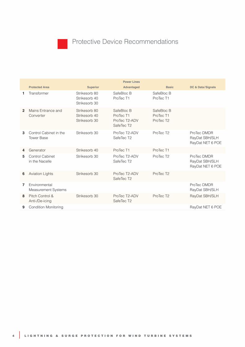
Protective Device Recommendations
Power Lines
Protected Area Superior Advantaged Basic DC & Data / Signals
1 Transformer Strikesorb 80 Strikesorb 40 Strikesorb 30
SafeBloc B ProTec T1
SafeBloc B ProTec T1
2 Mains Entrance and Converter
Strikesorb 80 Strikesorb 40 Strikesorb 30
SafeBloc B ProTec T1 ProTec T2-ADV SafeTec T2
SafeBloc B ProTec T1 ProTec T2
3 Control Cabinet in the Tower Base
Strikesorb 30 ProTec T2-ADV SafeTec T2
ProTec T2 ProTec DMDR RayDat SBH/SLH RayDat NET 6 POE
4 Generator Strikesorb 40 ProTec T1 ProTec T1
5 Control Cabinet in the Nacelle
Strikesorb 30 ProTec T2-ADV SafeTec T2
ProTec T2 ProTec DMDR RayDat SBH/SLH RayDat NET 6 POE
6 Aviation Lights Strikesorb 30 ProTec T2-ADV SafeTec T2
ProTec T2
7 Environmental Measurement Systems
ProTec DMDR RayDat SBH/SLH
8 Pitch Control & Anti-/De-icing
Strikesorb 30 ProTec T2-ADV SafeTec T2
ProTec T2 RayDat SBH/SLH
9 Condition Monitoring RayDat NET 6 POE

R a y c a p P r o d u c t S e l e c t i o n G u i d e | 5
Protective Devices for Wind Power Systems
Power Line
Signal Line
Down Conductor
6 | L I G H T N I N G & S U R G E P R O T E C T I O N F O R W I N D T U R B I N E S Y S T E M S
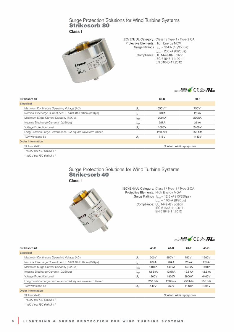
Strikesorb 80 80-D 80-F
Electrical
Maximum Continuous Operating Voltage (AC) Uc 550 V** 750 V*
Nominal Discharge Current per UL 1449 4th Edition (8/20 µs) In 20 kA 20 kA
Maximum Surge Current Capacity (8/20 µs) Imax 200 kA 200 kA
Impulse Discharge Current (10/350 µs) Iimp 25 kA 25 kA
Voltage Protection Level Up 1600 V 2400 V
Long Duration Surge Performance 1kA square waveform 2msec 250 hits 250 hits
TOV withstand 5s UT 716 V 1143 V
Order Information
Strikesorb 80 Contact: [email protected]
*690V per IEC 61643-11
**480 V per IEC 61643-11
Strikesorb 40 40-B 40-D 40-F 40-G
Electrical
Maximum Continuous Operating Voltage (AC) Uc 300 V 550 V** 750 V* 1200 V
Nominal Discharge Current per UL 1449 4th Edition (8/20 µs) In 20 kA 20 kA 20 kA 20 kA
Maximum Surge Current Capacity (8/20 µs) Imax 140 kA 140 kA 140 kA 140 kA
Impulse Discharge Current (10/350 µs) Iimp 12.5 kA 12.5 kA 12.5 kA 12.5 kA
Voltage Protection Level Up 1200 V 1800 V 2800 V 4400 V
Long Duration Surge Performance 1kA square waveform 2msec 250 hits 250 hits 250 hits 250 hits
TOV withstand 5s UT 442 V 762V 1143 V 1905 V
Order Information
Strikesorb 40 Contact: [email protected]
*690V per IEC 61643-11
**480 V per IEC 61643-11
IEC / EN / UL Category: Class I / Type 1 / Type 2 CAProtective Elements: High Energy MOV
Surge Ratings Iimp = 25 kA (10/350 µs) Imax = 200 kA (8/20 µs)
Compliance: UL 1449 4th Edition IEC 61643-11: 2011 EN 61643-11:2012
Surge Protection Solutions for Wind Turbine Systems Strikesorb 80 Class I
Surge Protection Solutions for Wind Turbine Systems Strikesorb 40 Class I
IEC / EN / UL Category: Class I / Type 1 / Type 2 CAProtective Elements: High Energy MOV
Surge Ratings Iimp = 12.5 kA (10/350 µs) Imax = 140 kA (8/20 µs)
Compliance: UL 1449 4th Edition IEC 61643-11: 2011 EN 61643-11:2012
�
�

R a y c a p P r o d u c t S e l e c t i o n G u i d e | 7
Enhanced Strikesorb 30 30-B 30-D
Electrical
Maximum Continuous Operating Voltage (AC) Uc 275 V 550 V*
Nominal Discharge Current per UL 1449 4th Edition (8/20 µs) In 20 kA 20 kA
Maximum Surge Current Capacity (8/20 µs) Imax 60 kA 60 kA
Impulse Discharge Current (10/350 µs) Iimp 7.5 kA 7.5 kA
Voltage Protection Level Up 1200 V 2200 V
TOV withstand 5s UT 442 V 762 V
Order Information
Strikesorb 30 Contact: [email protected]
*480 V per IEC 61643-11
Surge Protection Solutions for Wind Turbine Systems Strikesorb 30 Class I + II
IEC / EN / UL Category: Class I+II / Type 1+2 / Type 2 CAProtective Elements: High Energy MOV
Surge Ratings Iimp = 7.5 kA (10/350 µs) Imax = 60 kA (8/20 µs)
Compliance: UL 1449 4th Edition IEC 61643-11: 2011 EN 61643-11:2012
SafeBloc B(R) 12.5/750 (1+0) WT TCG 750
Electrical
Maximum Continuous Operating Voltage (AC) Uc 750 V
Nominal Discharge Current (8/20 µs) In 12.5 kA
Maximum Discharge Current (8/20 µs) Imax 40 kA
Impulse Discharge Current (10/350 µs) Iimp 12.55 kA
Voltage Protection Level Up < 2.6 kV
Short-Circuit Current Rating (AC) ISCCR 50 kA
TOV withstand 5s UT 1000 V
Order Information
SafeBloc B 25/750 (1+0) WT TCG 54.0590
SafeBloc BR 25/750 (1+0) WT TCG (with remote contacts) 54.0591
Compact Single Pole SPD for Wind Turbine SystemsSafeBloc B(R) 12.5 (1+0) WT TCGClass I + II
Location of Use: Main Distribution BoardsNetwork Systems: TN-S, TN-C, TT (only L-N)
Mode of Protection: L-PE, N - PE, L- PEN, L - NSurge Ratings: Iimp = 25 kA (10/350 µs)
Imax = 80 kA (8/20 µs)IEC/EN Category: Class I+II / Type 1, 2
Safety: High TOV ImmunityTechnology: Hybrid
Leakage Current Free : YesHousing: Compact Design
Compliance: IEC 61643-11:2011 EN 61643-11:2012
�
�

8 | L I G H T N I N G & S U R G E P R O T E C T I O N F O R W I N D T U R B I N E S Y S T E M S
Pluggable Multi-Pole SPD ProTec T1 3+0Class I + II
Location of Use: Main Distribution BoardsNetwork Systems: TN-C
Mode of Protection: L-PENSurge Ratings: Iimp = up to 12.5 kA (10/350 µs)
Imax = up to 50 kA (8/20 µs)IEC/EN/UL Category: Class I+II / Type 1+2 / Type 1 CA
Housing: Pluggable DesignCompliance: IEC 61643-11:2011
EN 61643-11:2012 UL 1449 4th Edition
ProTec T1-xxx-3+0(-R) 300 480 750
IEC Electrical
Maximum Continuous Operating Voltage (AC) Uc 300 V 480 V 750 V
Nominal Discharge Current (8/20 µs) In 20 kA 20 kA 20 kA
Maximum Discharge Current (8/20 µs) Imax 50 kA 50 kA 35 kA
Impulse Discharge Current (10/350 µs) Iimp 12.5 kA 10 kA 5 kA
Voltage Protection Level Up 1500 V 2100 V 3200 V
Back-Up Fuse (max) 315 A / 250 A gG 250 A gG
Short-Circuit Current Rating (AC) ISCCR 25 kA / 50 kA 50 kA
TOV Withstand 5s UT 337 V 581 V 871 V
Order Information
Order Code 300 480 750
ProTec T1-xxx-3+0 59.0031 59.0035 59.0037
ProTec T1-xxx-3+0-R (with remote contacts) 59.0032 59.0036 59.0038
Pluggable Multi-Pole SPD ProTec T1 2+0Class I + II
Location of Use: Main Distribution BoardsNetwork Systems: TN-S
Mode of Protection: L-PE, N-PESurge Ratings: Iimp = up to 12.5 kA (10/350 µs)
Imax = 50 kA (8/20 µs)IEC/EN/UL Category: Class I+II / Type 1+2 / Type 1 CA
Housing: Pluggable DesignCompliance: IEC 61643-11:2011
EN 61643-11:2012 UL 1449 4th Edition
ProTec T1-xxx-2+0(-R) 300 480
IEC Electrical
Maximum Continuous Operating Voltage (AC) Uc 300 V 480 V
Nominal Discharge Current (8/20 µs) In 20 kA 20 kA
Maximum Discharge Current (8/20 µs) Imax 50 kA 50 kA
Impulse Discharge Current (10/350 µs) Iimp 12.5 kA 10 kA
Voltage Protection Level Up 1500 V 2100 V
Back-Up Fuse (max) 315 A / 250 A gG
Short-Circuit Current Rating (AC) ISCCR 25 kA / 50 kA
TOV Withstand 5s UT 337 V 581 V
Order Information
Order Code 300 480
ProTec T1-xxx-2+0 59.0021 59.0025
ProTec T1-xxx-2+0-R (with remote contacts) 59.0022 59.0026
�
�

R a y c a p P r o d u c t S e l e c t i o n G u i d e | 9
Pluggable Multi-Pole SPD SafeTec T2 3+0Class II
Location of Use: Sub-distribution BoardsNetwork Systems: TN-C
Mode of Protection: L-PENSurge Ratings: Imax = up to 50 kA (8/20 µs)
IEC/EN/UL Category: Class II / Type 2 / Type 1 CASafety: Patented Current Limiting Technology
Housing: Pluggable DesignCompliance: IEC 61643-11:2011
EN 61643-11:2012 UL 1449 4th Edition
SafeTec T2-xxx-3+0(-R) 300 480 750
IEC Electrical
Maximum Continuous Operating Voltage (AC) Uc 300 V 480 V 750 V
Nominal Discharge Current (8/20 µs) In 20 kA 20 kA 20 kA
Maximum Discharge Current (8/20 µs) Imax 50 kA 50 kA 35 kA
Voltage Protection Level Up 1650 V 2300 V 3500 V
Back-Up Fuse (max) 315 A / 250 A gG
Short-Circuit Current Rating (AC) ISCCR 25 kA / 50 kA
TOV Withstand 120min UT 442 V 762 V 1200 V
Order Information
Order Code 300 480 750
SafeTec T2-xxx-3+0 59.0164 59.0168 59.0172
SafeTec T2-xxx-3+0-R (with remote contacts) 59.0165 59.0169 59.0173
Pluggable Multi-Pole SPD ProTec T2 3+0Class II
Location of Use: Sub-Distribution BoardsNetwork Systems: TN-C
Mode of Protection: L-PENSurge Ratings: Imax = up to 50 kA (8/20 µs)
IEC/EN/UL Category: Class II / Type 2 / Type 1 CAHousing: Pluggable Design
Compliance: IEC 61643-11:2011 EN 61643-11:2012 UL 1449 4th Edition
ProTec T2-xxx-3+0(-R) 300 480 750
IEC Electrical
Maximum Continuous Operating Voltage (AC) Uc 300 V 480 V 750 V
Nominal Discharge Current (8/20 µs) In 20 kA 20 kA 20 kA
Maximum Discharge Current (8/20 µs) Imax 50 kA 50 kA 35 kA
Voltage Protection Level Up 1500 V 2300 V 3400 V
Back-Up Fuse (max) 315 A / 250 A gG
Short-Circuit Current Rating (AC) ISCCR 25 kA / 50 kA
TOV Withstand 5s UT 337 V 581 V 871 V
Order Information
Order Code 300 480 750
ProTec T2-xxx-3+0 59.0093 59.0097 59.0099
ProTec T2-xxx-3+0-R (with remote contacts) 59.0094 59.0098 59.0100
�
�

10 | L I G H T N I N G & S U R G E P R O T E C T I O N F O R W I N D T U R B I N E S Y S T E M S
�
�
Pluggable Multi-Pole SPD ProTec T2-ADV 3+0Class II
Location of Use: Sub-Distribution BoardsNetwork Systems: TN-C
Mode of Protection: L-PENSurge Ratings: Imax= 50 kA (8/20 µs)
IEC/EN/UL Category: Class II / Type 2 / Type 1 CAHousing: Pluggable Design
Compliance: IEC 61643-11:2011 EN 61643-11:2012 UL 1449 4th Edition
ProTec T2-ADV-xxx-3+0(-R) 300 480
IEC Electrical
Maximum Continuous Operating Voltage (AC) Uc 300 V 480 V
Nominal Discharge Current (8/20 µs) In 20 kA 20 kA
Maximum Discharge Current (8/20 µs) Imax 50 kA 50 kA
Voltage Protection Level Up 1300 V 2000 V
Back-Up Fuse (max) 160A gG
Short-Circuit Current Rating (AC) ISCCR 50 kA
TOV Withstand 5s UT 337 V 581 V
Order Information
Order Code 300 480
ProTec T2-ADV-xxx-3+0 59.0230 59.0234
ProTec T2-ADV-xxx-3+0-R (with remote contacts) 59.0231 59.0235
Pluggable Multi-Pole SPD SafeTec T2 2+0Class II
Location of Use: Sub-distribution BoardsNetwork Systems: TN-S
Mode of Protection: L-PE, N-PESurge Ratings: Imax = 50 kA (8/20 µs)
IEC/EN/UL Category: Class II / Type 2 / Type 1 CASafety: Patented Current Limiting Technology
Housing: Pluggable DesignCompliance: IEC 61643-11:2011
EN 61643-11:2012 UL 1449 4th Edition
SafeTec T2-xxx-2+0(-R) 75 300 480
IEC Electrical
Maximum Continuous Operating Voltage (AC) Uc 75 V 300 V 480 V
Nominal Discharge Current (8/20 µs) In 20 kA 20 kA 20 kA
Maximum Discharge Current (8/20 µs) Imax 50 kA 50 kA 50 kA
Voltage Protection Level Up 800 V 1650 V 2300 V
Back-Up Fuse (max) 315 A / 250 A gG
Short-Circuit Current Rating (AC) ISCCR 25 kA / 50 kA
TOV Withstand 120min UT 150 V 442 V 762 V
Order Information
Order Code 75 300 480
SafeTec T2-xxx-2+0 59.0345 59.0150 59.0154
SafeTec T2-xxx-2+0-R (with remote contacts) 59.0346 59.0151 59.0155

R a y c a p P r o d u c t S e l e c t i o n G u i d e | 11
�
�
Pluggable Multi-Pole SPD ProTec T2 2+0Class II
Location of Use: Sub-Distribution BoardsNetwork Systems: TN-S
Mode of Protection: L-PE, N-PESurge Ratings: Imax = 50 kA (8/20 µs)
IEC/EN/UL Category: Class II / Type 2 / Type 1 CAHousing: Pluggable Design
Compliance: IEC 61643-11:2011 EN 61643-11:2012 UL 1449 4th Edition
ProTec T2-xxx-2+0(-R) 75 300 480
IEC Electrical
Maximum Continuous Operating Voltage (AC) Uc 75 V 300 V 480 V
Nominal Discharge Current (8/20 µs) In 20 kA 20 kA 20 kA
Maximum Discharge Current (8/20 µs) Imax 50 kA 50 kA 50 kA
Voltage Protection Level Up 800 V 1500 V 2300 V
Back-Up Fuse (max) 315 A / 250 A gG
Short-Circuit Current Rating (AC) ISCCR 25 kA / 50 kA
TOV Withstand 5s UT 114 V 337 V 581 V
Order Information
Order Code 75 300 480
ProTec T2-xxx-2+0 59.0343 59.0083 59.0087
ProTec T2-xxx-2+0-R (with remote contacts) 59.0344 59.0084 59.0088
Pluggable Multi-Pole SPD ProTec T2-ADV 2+0Class II
Location of Use: Sub-Distribution BoardsNetwork Systems: TN-S
Mode of Protection: L-PE, N-PESurge Ratings: Imax= 50 kA (8/20 µs)
IEC/EN/UL Category: Class II / Type 2 / Type 1 CAHousing: Pluggable Design
Compliance: IEC 61643-11:2011 EN 61643-11:2012 UL 1449 4th Edition
ProTec T2-ADV-xxx-2+0(-R) 75 300 480
IEC Electrical
Maximum Continuous Operating Voltage (AC) Uc 75 V 300 V 480 V
Nominal Discharge Current (8/20 µs) In 20 kA 20 kA 20 kA
Maximum Discharge Current (8/20 µs) Imax 50 kA 50 kA 50 kA
Voltage Protection Level Up 600 V 1300 V 2000 V
Back-Up Fuse (max) 160A gG
Short-Circuit Current Rating (AC) ISCCR 50 kA
TOV Withstand 5s UT 114 V 337 V 581 V
Order Information
Order Code 75 300 480
ProTec T2-ADV-xxx-2+0 59.0347 59.0222 59.0226
ProTec T2-ADV-xxx-2+0-R (with remote contacts) 59.0348 59.0223 59.0227

12 | L I G H T N I N G & S U R G E P R O T E C T I O N F O R W I N D T U R B I N E S Y S T E M S
IEC/EN Category: D1, C1, C2, C3Protection: All 4 Pairs
Voltages: 48 V DCMaximum Operating
Voltage: 50 VFrequency Range: 250 MHz, up to Cat 6, POE Compatible
Surge Discharge Ratings: In: 10 kA, Iimp: 1 kAEnclosure: UTB In-line Patch, DIN Rail MountTerminals: RJ45, Shielded
Housing: Compact DesignCompliance: IEC/EN 61643-21
UL 497B 4th Edition
SPD for Category 6 LAN Networks RayDat NET 6 POE D1 • C1 • C2 • C3
RayDat NET 6 48
Electrical
Nominal Operating Voltage (DC) Un 48 V
Maximum Continuous Operating Voltage (DC) (Line-Line) Uc 50 V
Rated Load Current at 25ºC IL 1 A
Nominal Discharge Current (8/20 µs) (Line-Line) In 150 A
C2 Total Discharge Current (8/20 µs) (Lines-Ground) Imax 10 kA
D1 Impulse Current (10/350 µs) Iimp 1 kA
Voltage Protection Level at In (Line-Line) Up 150 V
(Line-Ground) 550 V
Order Information
RayDat NET 6 706 312
Pluggable Multi-pole SPDProTec DMDR 20 Series Class III
ProTec DMDR 20/xxx 24 48 60 120
Electrical
Maximum Continuous Operating Voltage (AC) Uc 24 V 48 V 60 V 120 V
Open Circuit Voltage of the Combination Wave Generator (1.2/50 µs) Uoc 2.4 kV 2.4 kV 6 kV 6 kV
Short Circuit Current of the Combination Wave Generator (8/20 µs) Icw 1.2 kA 1.2 kA 3 kA 3 kA
Maximum Discharge Current (8/20 µs) Imax 2 kA 2 kA 4 kA 4 kA
Voltage Protection Level (L - N) Up < 250 V < 500 V < 600 V < 1100 V
(L - PE) / (N - PE) < 700 V < 800 V < 850 V < 1200 V
Short-Circuit Current Rating (AC) ISCCR 2 kA 2 kA 2 kA 2 kA
Order Information
ProTec DMDR 20/xxx 510 783 510 833 510 834 510 835
Location of Use: Sub-distribution BoardsNetwork Systems: TN-S
Mode of Protection: L - PE, N - PE, L - NSurge Ratings: Uoc /Icw = up to 6 kV/3 kA
Imax = up to 4 kA (8/20 µs)IEC/EN Category: Class III / Type 3
Housing: Modular DesignCompliance: IEC 61643-11:2011
EN 61643-11:2012
�
�
R a y c a p P r o d u c t S e l e c t i o n G u i d e | 13
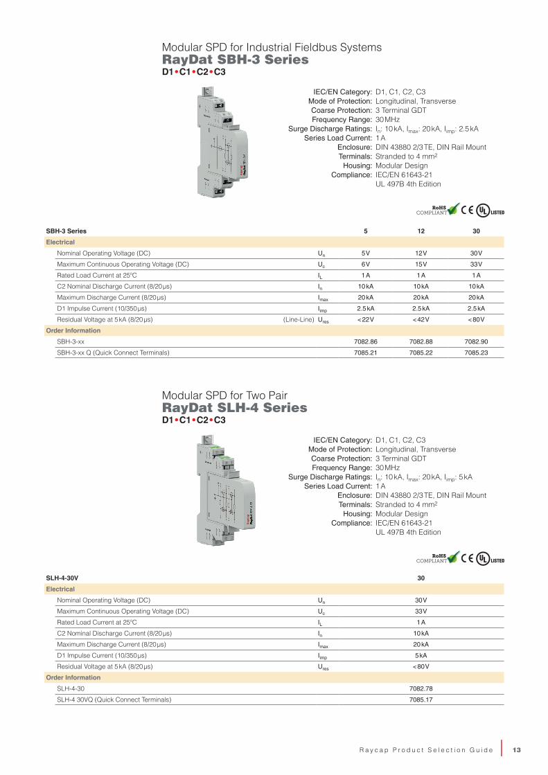
Modular SPD for Industrial Fieldbus Systems RayDat SBH-3 Series D1 • C1 • C2 • C3
SBH-3 Series 5 12 30
Electrical
Nominal Operating Voltage (DC) Un 5 V 12 V 30 V
Maximum Continuous Operating Voltage (DC) Uc 6 V 15 V 33 V
Rated Load Current at 25ºC IL 1 A 1 A 1 A
C2 Nominal Discharge Current (8/20 µs) In 10 kA 10 kA 10 kA
Maximum Discharge Current (8/20 µs) Imax 20 kA 20 kA 20 kA
D1 Impulse Current (10/350 µs) Iimp 2.5 kA 2.5 kA 2.5 kA
Residual Voltage at 5 kA (8/20 µs) (Line-Line) Ures < 22 V < 42 V < 80 V
Order Information
SBH-3-xx 7082.86 7082.88 7082.90
SBH-3-xx Q (Quick Connect Terminals) 7085.21 7085.22 7085.23
Modular SPD for Two Pair RayDat SLH-4 Series D1 • C1 • C2 • C3
SLH-4-30V 30
Electrical
Nominal Operating Voltage (DC) Un 30 V
Maximum Continuous Operating Voltage (DC) Uc 33 V
Rated Load Current at 25ºC IL 1 A
C2 Nominal Discharge Current (8/20 µs) In 10 kA
Maximum Discharge Current (8/20 µs) Imax 20 kA
D1 Impulse Current (10/350 µs) Iimp 5 kA
Residual Voltage at 5 kA (8/20 µs) Ures < 80 V
Order Information
SLH-4-30 7082.78
SLH-4 30VQ (Quick Connect Terminals) 7085.17
IEC/EN Category: D1, C1, C2, C3Mode of Protection: Longitudinal, Transverse Coarse Protection: 3 Terminal GDTFrequency Range: 30 MHz
Surge Discharge Ratings: In: 10 kA, Imax: 20 kA, Iimp: 5 kASeries Load Current: 1 A
Enclosure: DIN 43880 2/3 TE, DIN Rail MountTerminals: Stranded to 4 mm2
Housing: Modular DesignCompliance: IEC/EN 61643-21
UL 497B 4th Edition
IEC/EN Category: D1, C1, C2, C3Mode of Protection: Longitudinal, Transverse Coarse Protection: 3 Terminal GDTFrequency Range: 30 MHz
Surge Discharge Ratings: In: 10 kA, Imax: 20 kA, Iimp: 2.5 kASeries Load Current: 1 A
Enclosure: DIN 43880 2/3 TE, DIN Rail MountTerminals: Stranded to 4 mm2
Housing: Modular DesignCompliance: IEC/EN 61643-21
UL 497B 4th Edition
�
�
14 | L I G H T N I N G & S U R G E P R O T E C T I O N F O R W I N D T U R B I N E S Y S T E M S
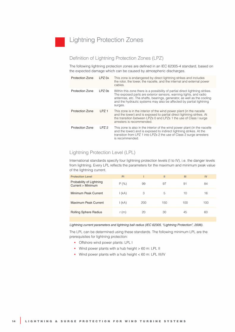
Definition of Lightning Protection Zones (LPZ)
The following lightning protection zones are defined in an IEC 62305-4 standard, based on the expected damage which can be caused by atmospheric discharges.
Protection Zone LPZ 0A This zone is endangered by direct lightning strikes and includes the rotor, the tower, the nacelle, and the internal and external power cables.
Protection Zone LPZ 0B Within this zone there is a possibility of partial direct lightning strikes. The exposed parts are exterior sensors, warning lights, and radio antennas, etc. The shafts, bearings, generator, as well as the cooling and the hydraulic systems may also be affected by partial lightning surges.
Protection Zone LPZ 1 This zone is in the interior of the wind power plant (in the nacelle and the tower) and is exposed to partial direct lightning strikes. At the transition between LPZs 0 and LPZs 1 the use of Class I surge arresters is recommended.
Protection Zone LPZ 2 This zone is also in the interior of the wind power plant (in the nacelle and the tower) and is exposed to indirect lightning strikes. At the transition from LPZ 1 into LPZs 2 the use of Class 2 surge arresters is recommended.
Lightning Protection Level (LPL)
International standards specify four lightning protection levels (I to IV), i.e. the danger levels from lightning. Every LPL reflects the parameters for the maximum and minimum peak value of the lightning current.
Protection Level PI I II III IV
Probability of Lightning Current > Minimum P (%) 99 97 91 84
Minimum Peak Current I (kA) 3 5 10 16
Maximum Peak Current I (kA) 200 150 100 100
Rolling Sphere Radius r (m) 20 30 45 60
Lightning current parameters and lightning ball radius (IEC 62305, “Lightning Protection”, 2006).
The LPL can be determined using these standards. The following minimum LPL are the prerequisites for lightning protection:
• Offshore wind power plants: LPL I
• Wind power plants with a hub height > 60 m: LPL II
• Wind power plants with a hub height < 60 m: LPL III/IV
Lightning Protection Zones

We reserve the right to introduce changes in performance, dimensions and materials in the course of technical progress. Copyright Raycap all rights reserved. No part of this work, nor of the information laid down herein and/or derivable here from and/or developed in connection with, may be reproduced or used in any form or by any means. Legal action will be taken against infringements. This publication replaces previous editions and the content herein is subject to change at any time without notice.

Raycap and Strikesorb are registered trademarks.© 2020 Raycap All rights reserved.
G02-01-125 200124
Raycap Worldwide Locations
Raycap Inc. 806 South Clearwater Loop Post Falls, ID 83854 United States of America
7555-A Palmetto Commerce Pkwy North Charleston, SC 29420 United States of America
Raycap GmbH Parkring 11 85748 Garching Munich Germany
Raycap S.A. Telou & Petroutsou 14 15124 Maroussi Athens Greece
Raycap S.A. Manufacturing Industrial Area of Drama 66100 Drama Greece
Raycap d.o.o. Pod hrasti 7 Poslovna cona Zeje pri Komendi 1218 Komenda Slovenia
Raycap Cyprus Ltd. 46 Lefkosias Street Industrial Area of Dali 2540 Nicosia Cyprus
Raycap SAS 84 rue Charles Michels Building B 93200 Saint-Denis France
Raycap Corporation SRL 4A, Johann Strauss, 4 Floor Sector 2, 020312 Bucharest Romania
Raycap (Suzhou) Co. Ltd. Block B, Phase II of New Sea Union No. 58 Heshun Road SIP, Suzhou 215122 Jiangsu Province China
raycap.com • [email protected]