Embed Size (px)
Citation preview
Lightning Protection By
Wes Atchison WA5TKU

Overview
• Lightning Protection Is a Very Broad Subject – To Little Time to Cover Everything – Tried to Cover Most Important Points
• Each Site Needs Survey Before Implementing Lightning Protection
• Plan Out Protection System
Qualifications
• NOT AN EXPERT • Experience
– Licensed in 1965 as WN5MAF – Employed in Telecom Wireline and Wireless
Industry for Over 10 Years – Employed by Local Power Company in Secondary
Distribution for 2 Years
Lightning Protection Basics
• Lightning Protection is RISK MEDIATION – Personnel Safety – Damage Reduction
• Lightning Protection is NOT PREVENTION • Lightning Protection Systems Reduce Damage • Lightning Protection Is A Tradeoff Of Cost OF
System To Cost Of Damage
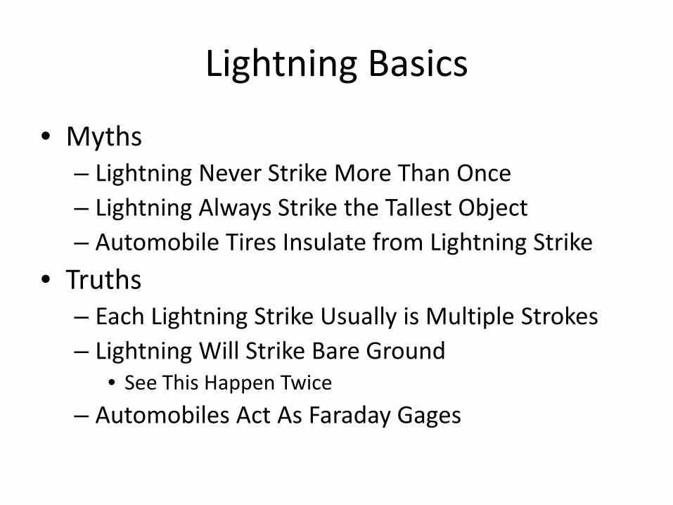
Lightning Basics
• Myths – Lightning Never Strike More Than Once – Lightning Always Strike the Tallest Object – Automobile Tires Insulate from Lightning Strike
• Truths – Each Lightning Strike Usually is Multiple Strokes – Lightning Will Strike Bare Ground
• See This Happen Twice – Automobiles Act As Faraday Gages
Lightning Basics
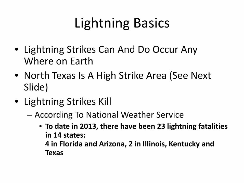
• Lightning Strikes Can And Do Occur Any Where on Earth
• North Texas Is A High Strike Area (See Next Slide)
• Lightning Strikes Kill – According To National Weather Service
• To date in 2013, there have been 23 lightning fatalities in 14 states: 4 in Florida and Arizona, 2 in Illinois, Kentucky and Texas
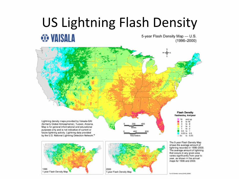
US Lightning Flash Density
Lightning Basics
• Lightning Strike Locations Can Be Tracked • Insurance Companies Use This Data For Claims • Services Are Available For Strike Location
Information – Example on Next Slide
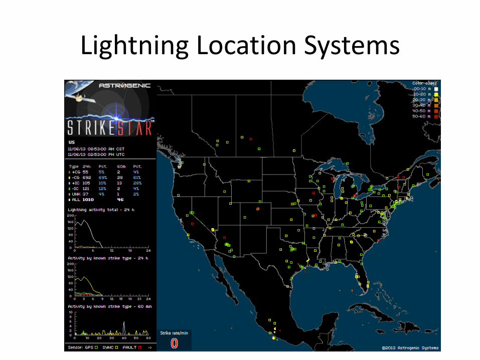
Lightning Location Systems
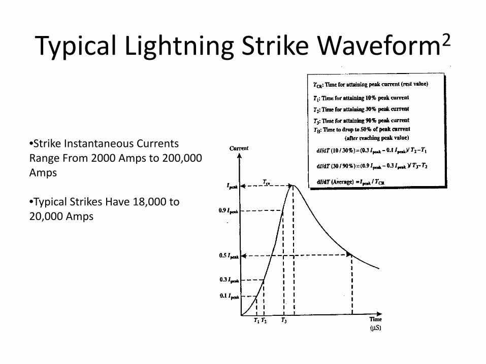
Typical Lightning Strike Waveform2
•Strike Instantaneous Currents Range From 2000 Amps to 200,000 Amps
•Typical Strikes Have 18,000 to 20,000 Amps
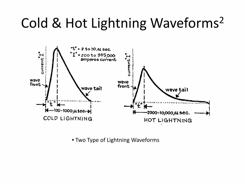
Cold & Hot Lightning Waveforms2
• Two Type of Lightning Waveforms
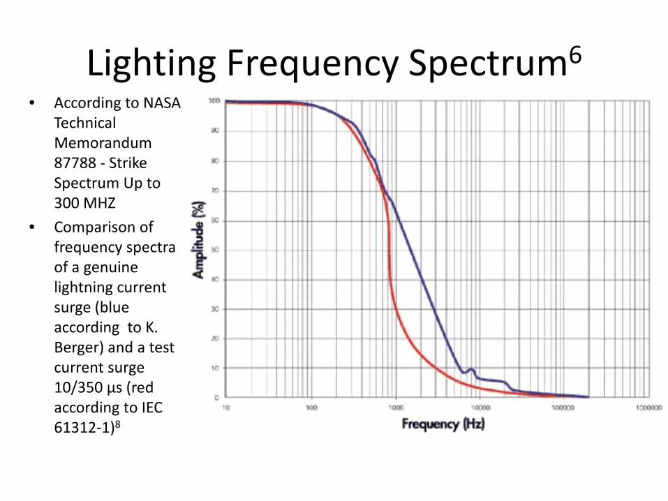
Lighting Frequency Spectrum6 • According to NASA
Technical Memorandum 87788 - Strike Spectrum Up to 300 MHZ
• Comparison of frequency spectra of a genuine lightning current surge (blue according to K. Berger) and a test current surge 10/350 µs (red according to IEC 61312-1)8
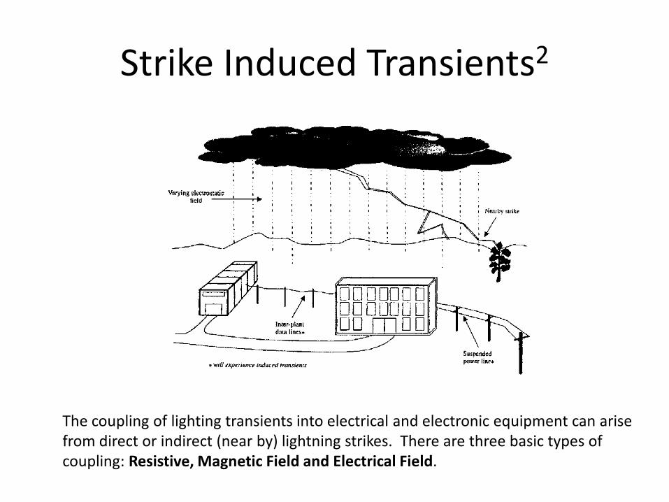
Strike Induced Transients2
The coupling of lighting transients into electrical and electronic equipment can arise from direct or indirect (near by) lightning strikes. There are three basic types of coupling: Resistive, Magnetic Field and Electrical Field.
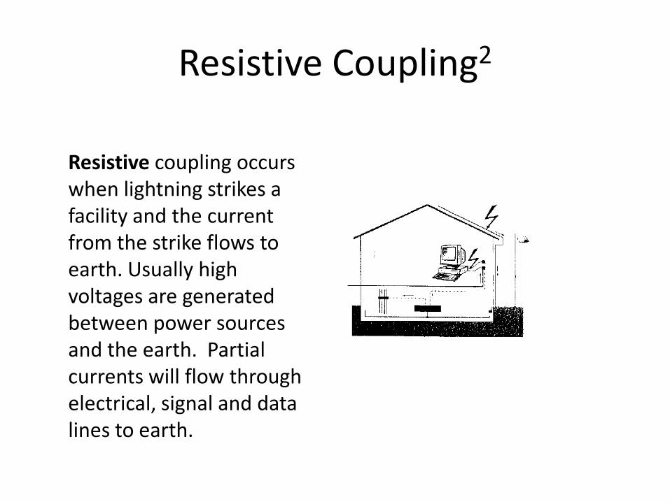
Resistive Coupling2
Resistive coupling occurs when lightning strikes a facility and the current from the strike flows to earth. Usually high voltages are generated between power sources and the earth. Partial currents will flow through electrical, signal and data lines to earth.
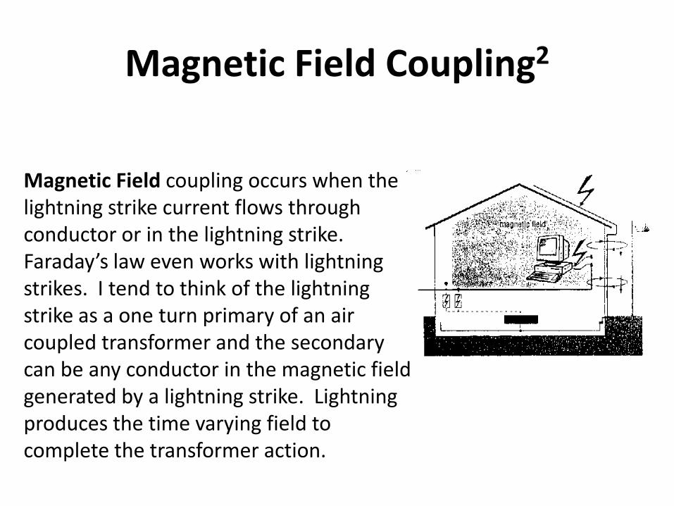
Magnetic Field Coupling2
Magnetic Field coupling occurs when the lightning strike current flows through conductor or in the lightning strike. Faraday’s law even works with lightning strikes. I tend to think of the lightning strike as a one turn primary of an air coupled transformer and the secondary can be any conductor in the magnetic field generated by a lightning strike. Lightning produces the time varying field to complete the transformer action.
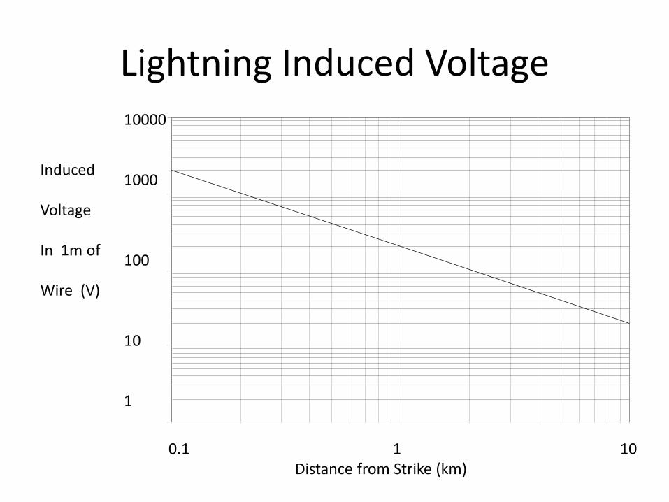
Lightning Induced Voltage
0.1 1 10 Distance from Strike (km)
10000 1000 100 10 1
Induced Voltage In 1m of Wire (V)
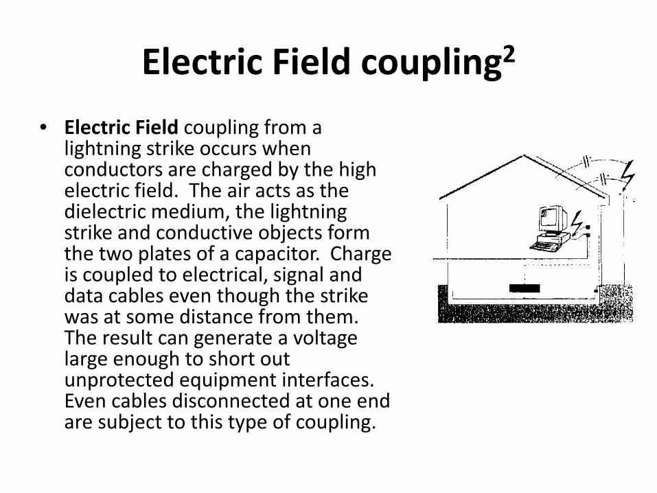
Electric Field coupling2 • Electric Field coupling from a
lightning strike occurs when conductors are charged by the high electric field. The air acts as the dielectric medium, the lightning strike and conductive objects form the two plates of a capacitor. Charge is coupled to electrical, signal and data cables even though the strike was at some distance from them. The result can generate a voltage large enough to short out unprotected equipment interfaces. Even cables disconnected at one end are subject to this type of coupling.
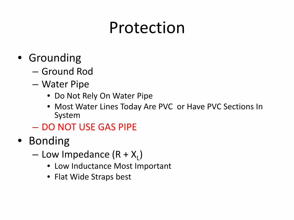
Protection
• Grounding – Ground Rod – Water Pipe
• Do Not Rely On Water Pipe • Most Water Lines Today Are PVC or Have PVC Sections In
System – DO NOT USE GAS PIPE
• Bonding – Low Impedance (R + XL)
• Low Inductance Most Important • Flat Wide Straps best
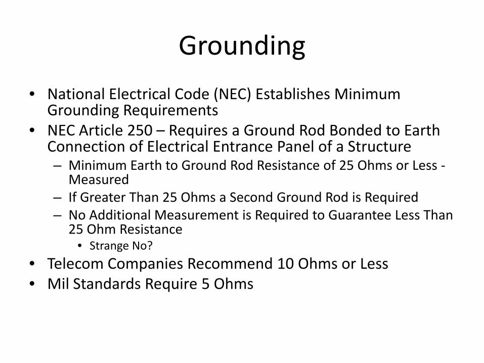
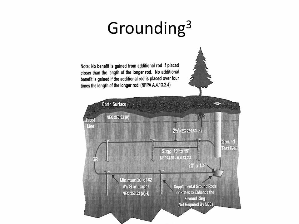
Grounding • National Electrical Code (NEC) Establishes Minimum
Grounding Requirements • NEC Article 250 – Requires a Ground Rod Bonded to Earth
Connection of Electrical Entrance Panel of a Structure – Minimum Earth to Ground Rod Resistance of 25 Ohms or Less -
Measured – If Greater Than 25 Ohms a Second Ground Rod is Required – No Additional Measurement is Required to Guarantee Less Than
25 Ohm Resistance • Strange No?
• Telecom Companies Recommend 10 Ohms or Less • Mil Standards Require 5 Ohms
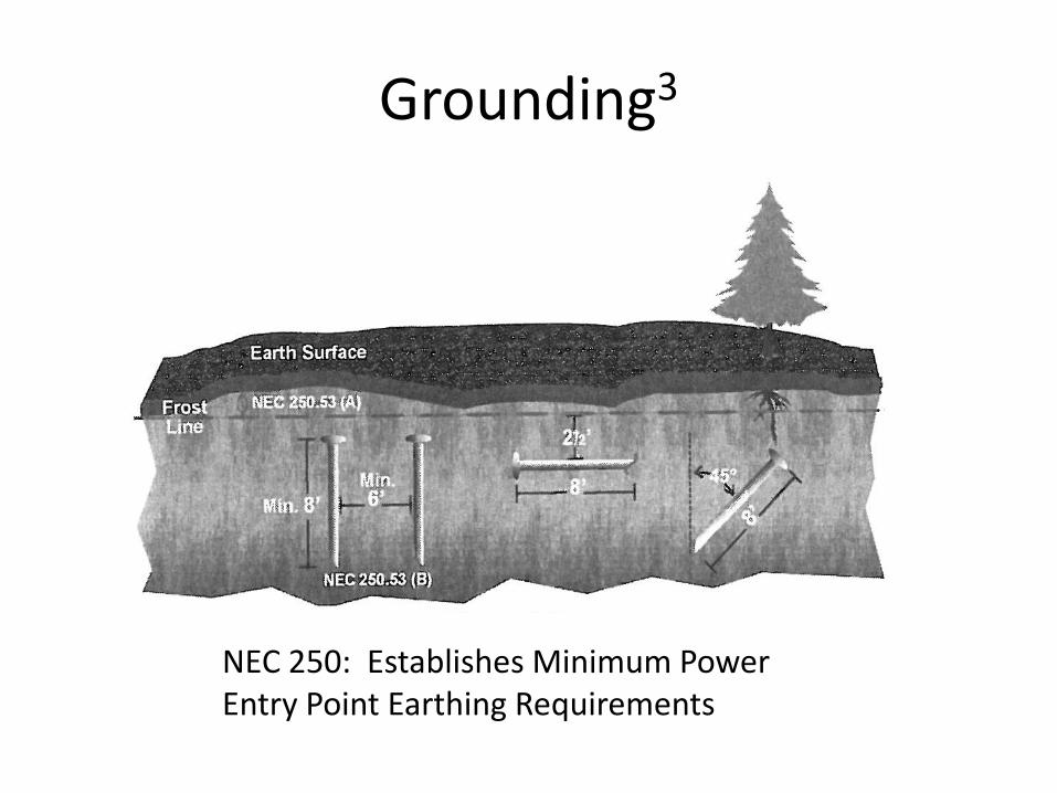
Grounding3
NEC 250: Establishes Minimum Power Entry Point Earthing Requirements
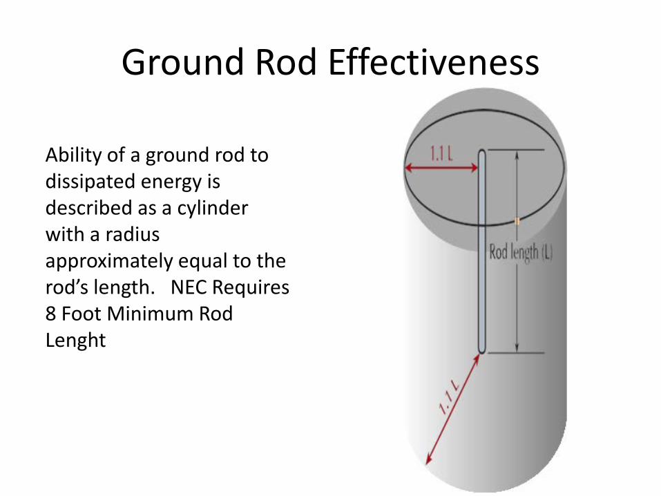
Ground Rod Effectiveness
Ability of a ground rod to dissipated energy is described as a cylinder with a radius approximately equal to the rod’s length. NEC Requires 8 Foot Minimum Rod Lenght
Grounding3
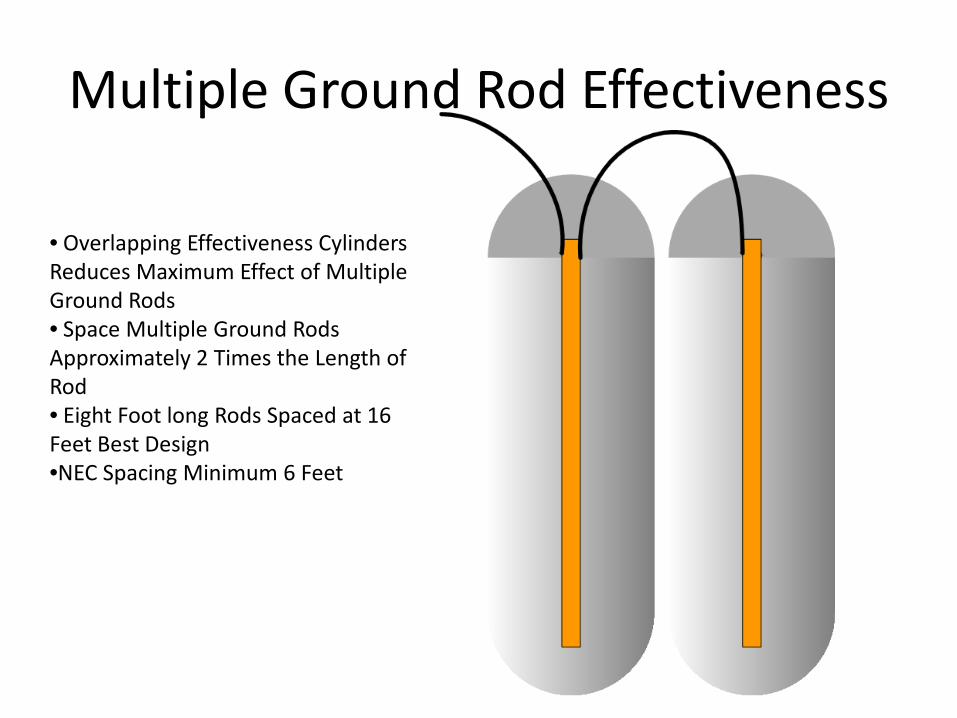
Multiple Ground Rod Effectiveness
• Overlapping Effectiveness Cylinders Reduces Maximum Effect of Multiple Ground Rods • Space Multiple Ground Rods Approximately 2 Times the Length of Rod • Eight Foot long Rods Spaced at 16 Feet Best Design •NEC Spacing Minimum 6 Feet
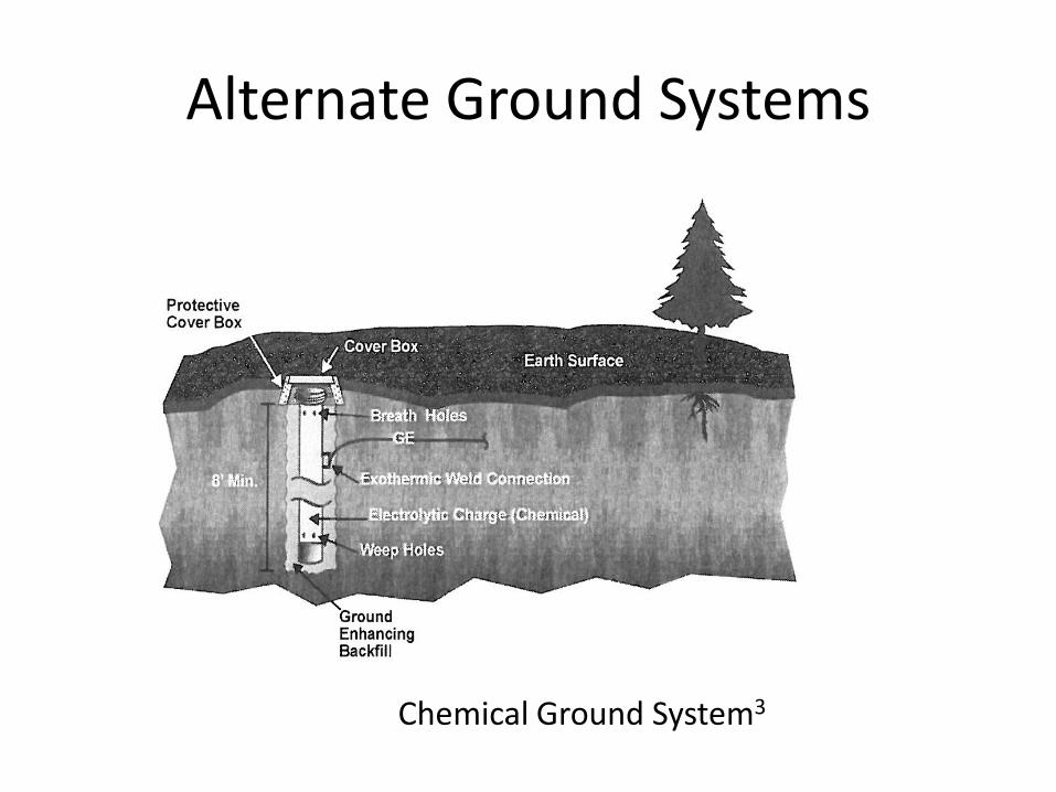
Alternate Ground Systems
Chemical Ground System3
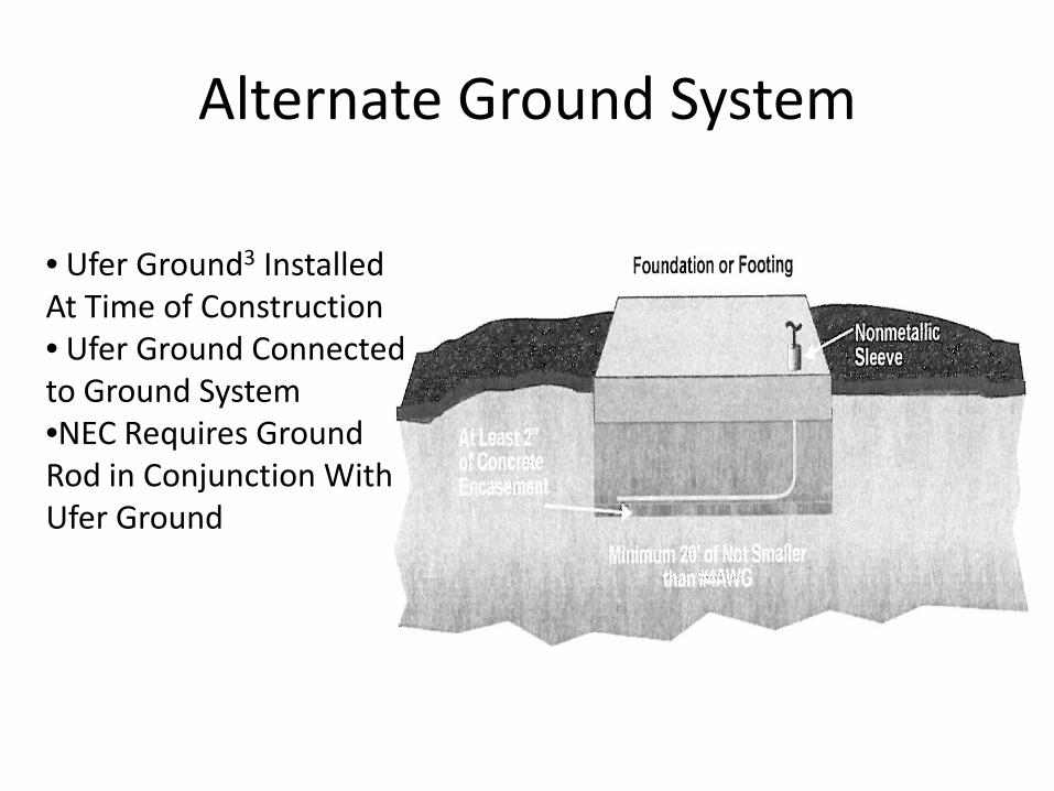
Alternate Ground System
• Ufer Ground3 Installed At Time of Construction • Ufer Ground Connected to Ground System •NEC Requires Ground Rod in Conjunction With Ufer Ground
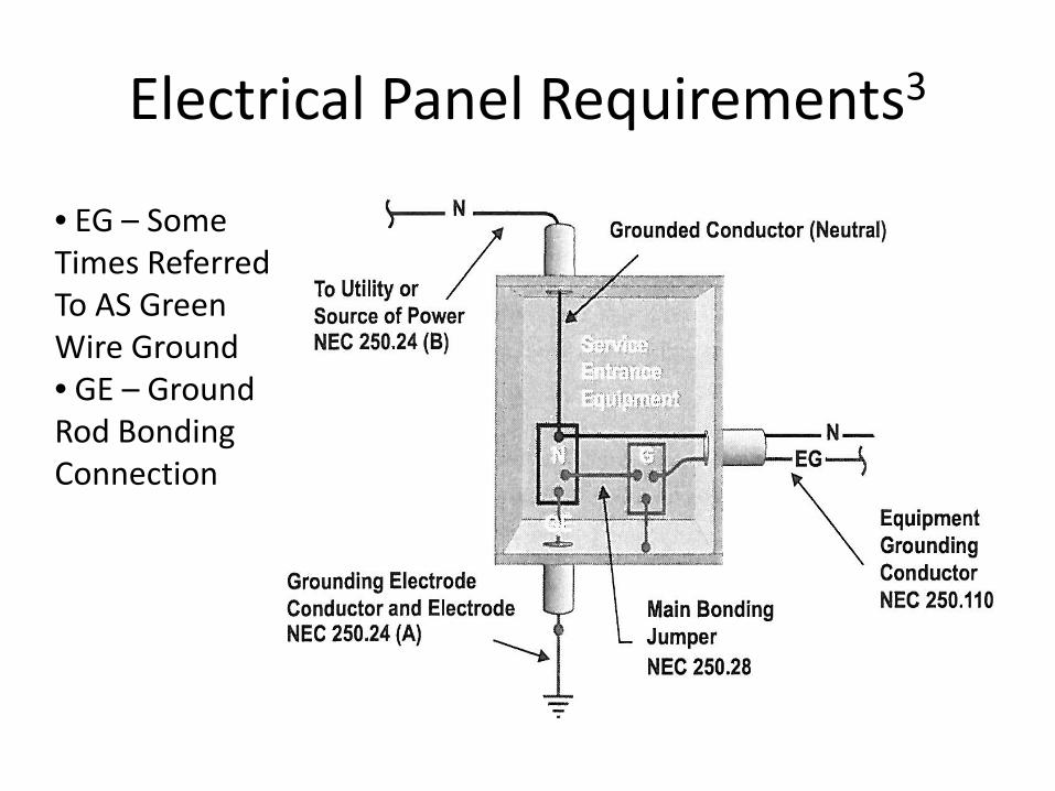
Electrical Panel Requirements3
• EG – Some Times Referred To AS Green Wire Ground • GE – Ground Rod Bonding Connection
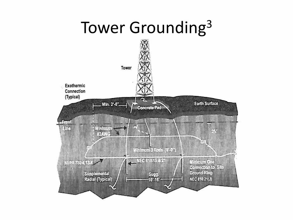
Tower Grounding3
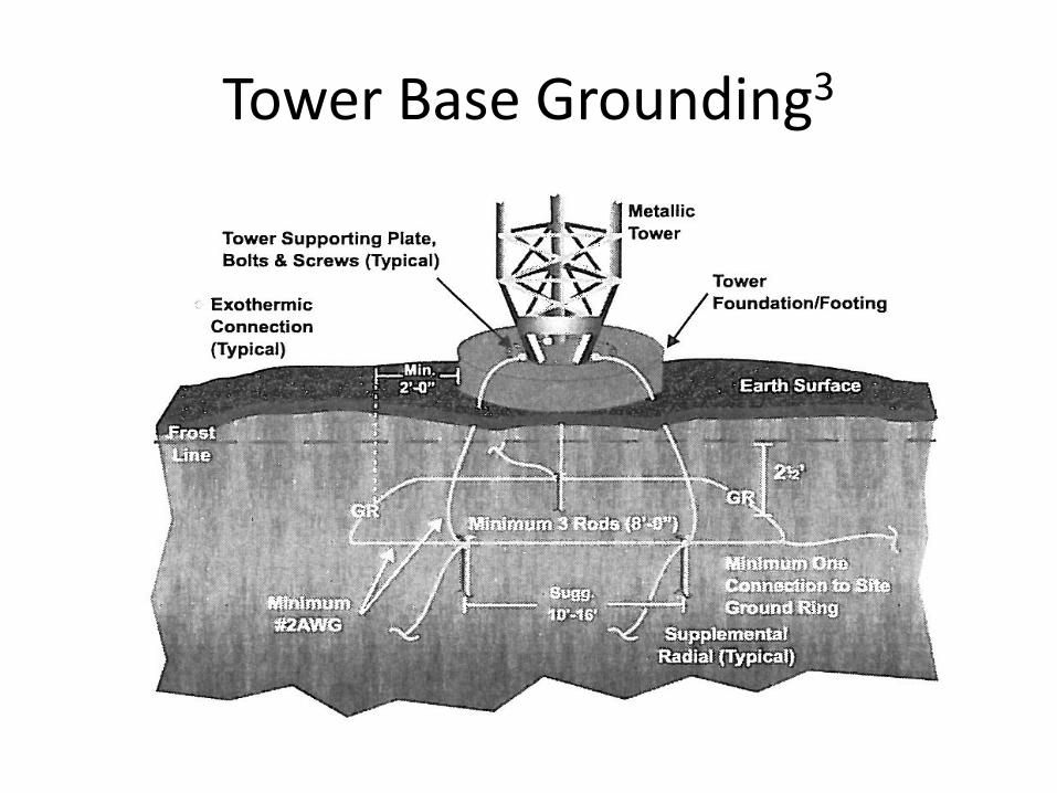
Tower Base Grounding3
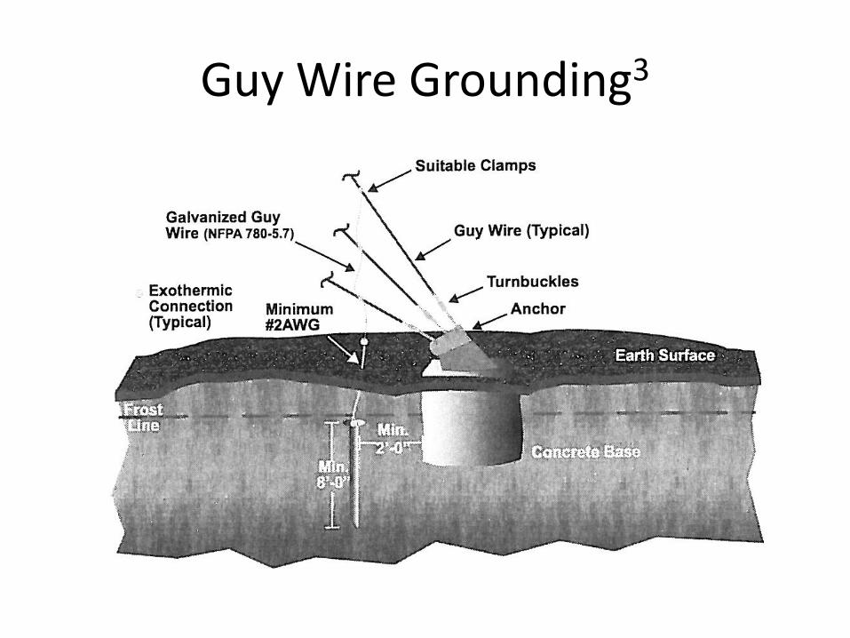
Guy Wire Grounding3
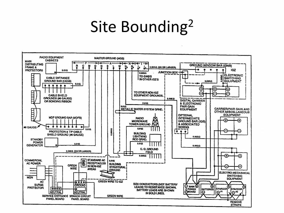
Site Bounding2
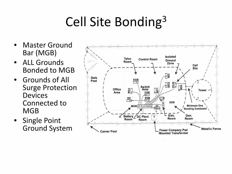
Cell Site Bonding3 • Master Ground
Bar (MGB) • ALL Grounds
Bonded to MGB • Grounds of All
Surge Protection Devices Connected to MGB
• Single Point Ground System
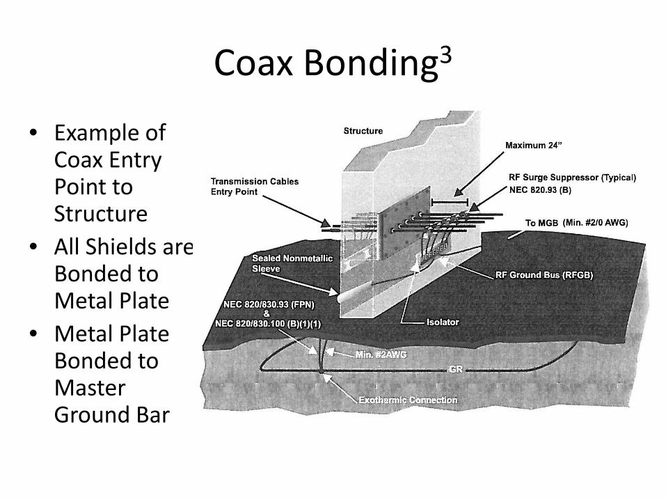
Coax Bonding3
• Example of Coax Entry Point to Structure
• All Shields are Bonded to Metal Plate
• Metal Plate Bonded to Master Ground Bar
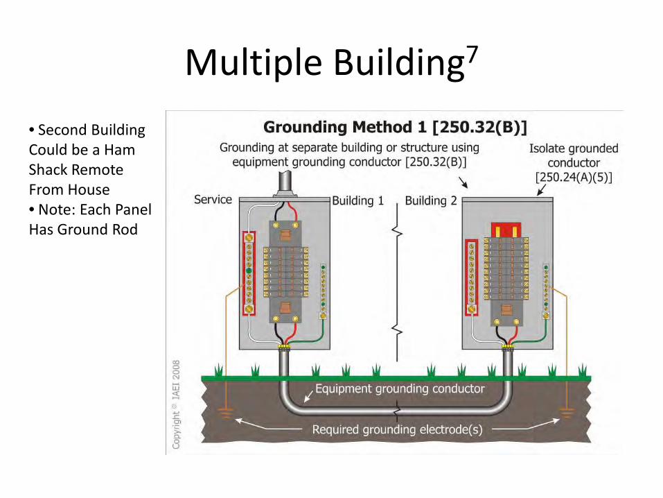
Multiple Building7
• Second Building Could be a Ham Shack Remote From House • Note: Each Panel Has Ground Rod
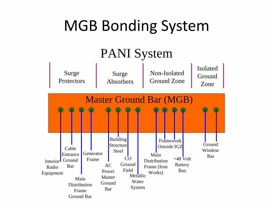
MGB Bonding System
Interior Radio
Equipment
Cable Entrance Ground
Bar
Main Distribution
Frame Ground Bar
Generator Frame
AC Power Master Ground
Bar
Building Structure
SteelCO
Ground Field
Metallic Water
System
Main Distribution Frame (Iron
Works)
Framework Outside IGZ
+48 Volt Battery
Bus
Ground Window
Bar
Surge Protectors
Surge Absorbers
Non-Isolated Ground Zone
Isolated Ground
Zone
Master Ground Bar (MGB)
PANI System
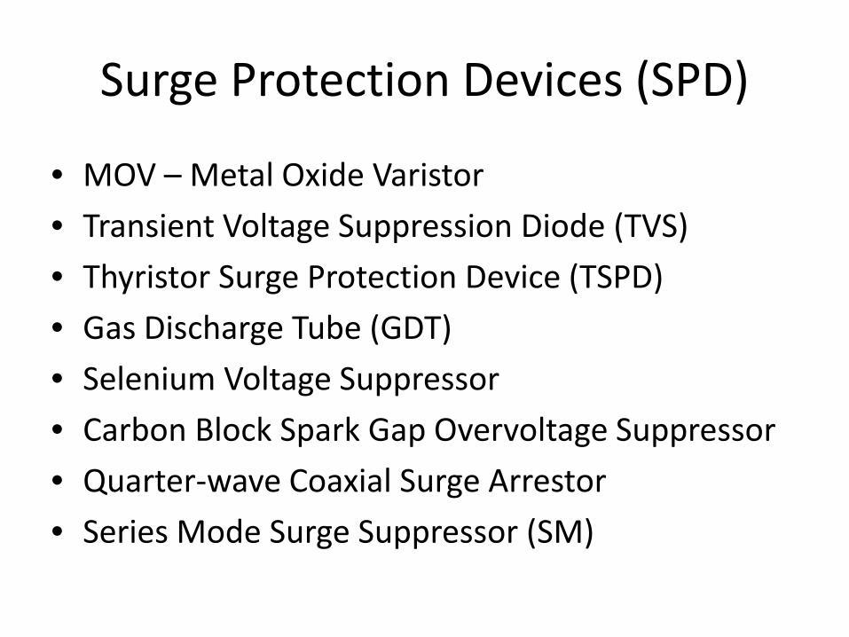
Surge Protection Devices (SPD)
• MOV – Metal Oxide Varistor • Transient Voltage Suppression Diode (TVS) • Thyristor Surge Protection Device (TSPD) • Gas Discharge Tube (GDT) • Selenium Voltage Suppressor • Carbon Block Spark Gap Overvoltage Suppressor • Quarter-wave Coaxial Surge Arrestor • Series Mode Surge Suppressor (SM)
Surge Protection Devices (SPD)
• Each SPD Has Specific Area of Use • Each Type Pro’s and Con’s • Improperly Use Can Cause problems • Subject to Large for this Presentation • Follow-On Presentation
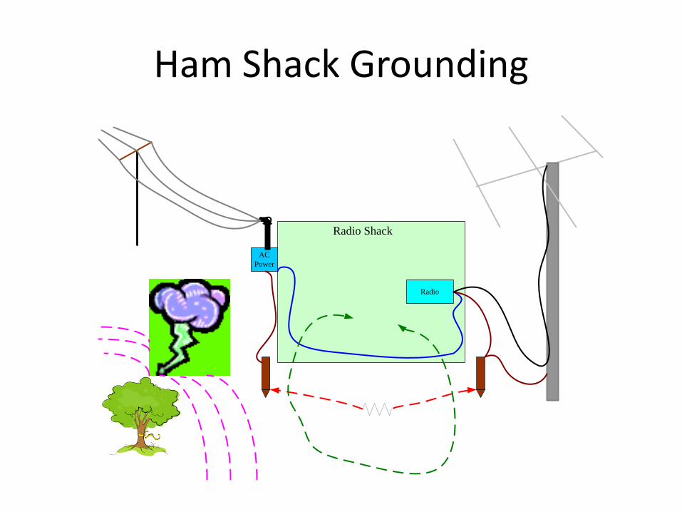
Ham Shack Grounding
Radio
AC Power
Radio Shack
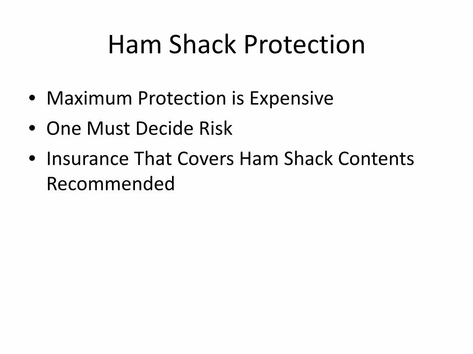
Ham Shack Protection
• Maximum Protection is Expensive • One Must Decide Risk • Insurance That Covers Ham Shack Contents
Recommended
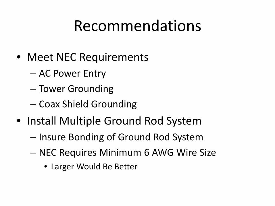
Recommendations
• Meet NEC Requirements – AC Power Entry – Tower Grounding – Coax Shield Grounding
• Install Multiple Ground Rod System – Insure Bonding of Ground Rod System – NEC Requires Minimum 6 AWG Wire Size
• Larger Would Be Better
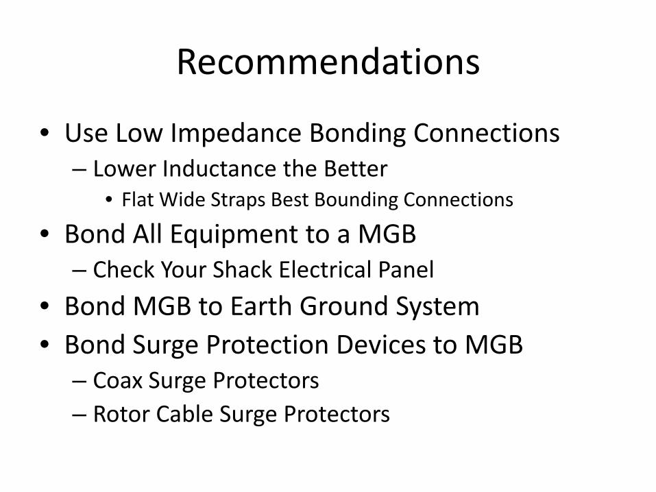
Recommendations
• Use Low Impedance Bonding Connections – Lower Inductance the Better
• Flat Wide Straps Best Bounding Connections
• Bond All Equipment to a MGB – Check Your Shack Electrical Panel
• Bond MGB to Earth Ground System • Bond Surge Protection Devices to MGB
– Coax Surge Protectors – Rotor Cable Surge Protectors
Recommendations
• Use Grounding Coax Switches – Bond Switch Ground to MGB – Place Switch in Grounding Position When not In
Use
Summary
• Lightning Protection Is a Very Broad Subject – To Little Time to Cover Everything – Tried to Cover Most Important Points
• Each Site Needs Survey Before Implementing Lightning Protection
• Plan Out Protection System
References
1. http://www.weather.gov/os/lightning/lightning_map.htm
2. National Lightning Safety Institute, Lightning Protection for Engineers, August 2006
3. RO Associates, Comprehensive Grounding and Protection of Communication Sites, September 2008
4. NFPA 70, National Electrical Code, 2005 5. NFPA 780, Standard for the Installation of Lightning
Protection Systems, 2008 Edition
References (cont.)
6. NASA Technical Memorandum 87788, Review of Measurements of the RF Spectrum of Radiation from Lightning, March 1986
7. http://fyi.uwex.edu/mrec/files/2011/04/W4.-Biesterveld-NEC-grounding-MREC2010.pdf
8. http://www2.hubersuhner.com/ms/products/hs-p-rf/hs-rf-lightning-protectors/hs-p-rf-lp-kb/hs-p-rf-lp-kb-bas/hs-p-rf-lp-kb-bas-fre.htm