Embed Size (px)
Citation preview

UNIVERSITY OF OSLODepartment of Informatics
Lightweight andFlexibleSingle-PathCongestionControl Coupling
PhD Thesis
Safiqul Islam
March 9, 2017


To Mom and Monita


Abstract
Communication between two Internet hosts using parallel connections may result inunwanted interference between the connections. In this dissertation, we propose asender-side solution to address this problem by letting the congestion controllers ofthe different connections collaborate, correctly taking congestion control logic intoaccount. In addition, this dissertation proposes a simple light-weight encapsulationmechanism that multiplexes the connections onto a single UDP-connection to ensurethe same bottleneck. Real-life experiments and simulations show that our solutionworks for a wide variety of congestion control mechanisms, provides great flexibilitywhen allocating application traffic to the connections, and results in lower queuingdelay and less packet loss.
iii


Acknowledgments
I would like to express my heartiest gratitude to my Ph.D. supervisors ProfessorMichael Welzl and Professor Stein Gjessing for helping me with critical reviews, pro-viding detailed background knowledge, and technical advice. Working with Michaeland Stein has taught me how to carry out research work and instilled courage inme to become a confident public speaker. Two “best paper” awards in one Ph.D.journey came out just because of them. They even helped me in non-technical mat-ters; especially Stein, for teaching me how to tie my shoelace on a train in Tokyo,Japan. It was quite embarrassing, but I learned it now. I especially want to thankMichael for his continuous encouragement and inspiration that helped me to lookbeyond the boundaries. I hope to be as energetic and enthusiastic as Michael sothat I can also command the audience as he does. This is not balderdash, I meanit.
I would want to thank David Hayes for his support and advice, especially forallowing me to disturb him for every silly question. I would also like to acknowledgeProfessor Grenville Armitage from Swinburne University of Technology, and Profes-sor Joe Touch from University of Southern California for their valuable suggestionsregarding TCP congestion control coupling.
I would like to thank my colleagues who have made my Ph.D. journey mem-orable, especially Abhishek Singh, Amir Taherkodi, Jonas Modahl Mørkas, KatjaElisabeth Andersson, Kashif Sana Dar, Kristian Hiorth, Lucas Provensi, NaeemKhademi, Narasimha Raghavan, Navneet Kumar Pandey, Runa Barik, Vinay Settyand Øystein Dale. I would like to extend my appreciation to Eskil Brun from theadministration who helped me recover my data when I badly needed them. I wouldalso like to thank Razib Hayat Khan and Rezaul Hoque for cheering me up wheneverI felt down.
I am grateful for the financial support during my research from the Departmentof Informatics, University of Oslo, Huawei Technologies Co., Ltd., the EuropeanUnions Horizon 2020 research and innovation programme (under grant agreementNo. 644334 (NEAT)), and the European Union through the FP7-ICT project RITE(under contract number 317700). In addition, I would like to thank the IETFRMCAT and IRTF ICCRG Working Groups, and all the partners from RITE and
v

NEAT for their fruitful and constructive discussions throughout my research work.I want to express my gratitude to my parents and my brother Khursheed Alam
for an immense amount of support throughout my life. Whatever I am, I oweespecially to you, Mom! Last but not least, I would like to thank my wife ZannatulNaim Monita for bearing with me throughout the Ph.D. work. I know thankingyou would not be enough, but, seriously, thank you.
Safiqul IslamOslo, March 9, 2017

Contents
Abstract iii
Acknowledgments v
I Overview 1
1 Introduction 3
1.1 Motivation . . . . . . . . . . . . . . . . . . . . . . . . . . . . . . . . 3
1.2 Research Questions . . . . . . . . . . . . . . . . . . . . . . . . . . . . 6
1.3 Research Objectives . . . . . . . . . . . . . . . . . . . . . . . . . . . 7
1.4 Research Methodology . . . . . . . . . . . . . . . . . . . . . . . . . . 7
1.4.1 Network Simulation . . . . . . . . . . . . . . . . . . . . . . . 8
1.4.2 Real-life Experiments . . . . . . . . . . . . . . . . . . . . . . 8
1.5 Published Works . . . . . . . . . . . . . . . . . . . . . . . . . . . . . 8
1.5.1 Research Papers in this Thesis . . . . . . . . . . . . . . . . . 9
1.5.2 Related Internet Drafts . . . . . . . . . . . . . . . . . . . . . 11
1.5.3 Short Summaries / Posters (Not Included in the Thesis) . . . 13
2 Background 15
2.1 Internet Congestion Control . . . . . . . . . . . . . . . . . . . . . . . 15
2.2 Coupled Congestion Control . . . . . . . . . . . . . . . . . . . . . . . 17
2.2.1 Single-Path Congestion Control Coupling . . . . . . . . . . . 17
2.2.2 Multiplexing . . . . . . . . . . . . . . . . . . . . . . . . . . . 19
2.2.3 Datacenter Capacity Management . . . . . . . . . . . . . . . 19
2.2.4 Multi-Path Congestion Control Coupling . . . . . . . . . . . 19
2.3 Shared Bottleneck Detection . . . . . . . . . . . . . . . . . . . . . . . 20
3 Contributions 21
3.1 Overview of the Main Contributions . . . . . . . . . . . . . . . . . . 22
3.2 ctrlTCP in Datacenters . . . . . . . . . . . . . . . . . . . . . . . . . 28
vii

4 Conclusions 33
4.1 Addressing Research Questions . . . . . . . . . . . . . . . . . . . . . 33
4.2 Future Directions . . . . . . . . . . . . . . . . . . . . . . . . . . . . . 35
4.2.1 Further Research . . . . . . . . . . . . . . . . . . . . . . . . . 35
4.2.2 Deployment . . . . . . . . . . . . . . . . . . . . . . . . . . . . 36
References 45
II Research Papers 47
5 Coupled Congestion Control for RTP Media 49
5.1 Introduction . . . . . . . . . . . . . . . . . . . . . . . . . . . . . . . . 49
5.2 Related Work . . . . . . . . . . . . . . . . . . . . . . . . . . . . . . . 50
5.3 The Flow State Exchange . . . . . . . . . . . . . . . . . . . . . . . . 51
5.4 Evaluation . . . . . . . . . . . . . . . . . . . . . . . . . . . . . . . . . 56
5.5 Conclusions . . . . . . . . . . . . . . . . . . . . . . . . . . . . . . . . 64
5.6 Acknowledgments . . . . . . . . . . . . . . . . . . . . . . . . . . . . . 65
References . . . . . . . . . . . . . . . . . . . . . . . . . . . . . . . . . . . . 65
6 Managing Real-Time Media Flows through a Flow State Exchange 67
6.1 Introduction . . . . . . . . . . . . . . . . . . . . . . . . . . . . . . . . 68
6.2 Background and related work . . . . . . . . . . . . . . . . . . . . . . 69
6.3 The Flow State Exchange (FSE) . . . . . . . . . . . . . . . . . . . . 70
6.3.1 Active vs. passive updates . . . . . . . . . . . . . . . . . . . . 70
6.3.2 Increasing and decreasing rates . . . . . . . . . . . . . . . . . 73
6.3.3 Application to NADA . . . . . . . . . . . . . . . . . . . . . . 74
Building a stable queue . . . . . . . . . . . . . . . . . . . . . 74
Accelerated ramp up . . . . . . . . . . . . . . . . . . . . . . . 74
Rate update frequency . . . . . . . . . . . . . . . . . . . . . . 74
6.3.4 Application to GCC . . . . . . . . . . . . . . . . . . . . . . . 75
Builds a stable queue . . . . . . . . . . . . . . . . . . . . . . 75
6.3.5 A simple passive FSE algorithm for NADA and GCC . . . . 76
6.4 Evaluation . . . . . . . . . . . . . . . . . . . . . . . . . . . . . . . . . 77
6.4.1 Prioritization results . . . . . . . . . . . . . . . . . . . . . . . 78
6.4.2 Test case results . . . . . . . . . . . . . . . . . . . . . . . . . 78
6.4.3 Delayed feedback tests . . . . . . . . . . . . . . . . . . . . . . 80
6.5 Conclusions . . . . . . . . . . . . . . . . . . . . . . . . . . . . . . . . 83
6.6 Acknowledgments . . . . . . . . . . . . . . . . . . . . . . . . . . . . . 83
References . . . . . . . . . . . . . . . . . . . . . . . . . . . . . . . . . . . . 83

7 Start Me Up: Determining and Sharing TCP’s Initial CongestionWindow 87
7.1 Introduction . . . . . . . . . . . . . . . . . . . . . . . . . . . . . . . . 87
7.2 Background . . . . . . . . . . . . . . . . . . . . . . . . . . . . . . . . 88
7.3 Design . . . . . . . . . . . . . . . . . . . . . . . . . . . . . . . . . . . 89
7.4 Conclusion . . . . . . . . . . . . . . . . . . . . . . . . . . . . . . . . 91
7.5 Acknowledgments . . . . . . . . . . . . . . . . . . . . . . . . . . . . . 92
References . . . . . . . . . . . . . . . . . . . . . . . . . . . . . . . . . . . . 92
8 OpenTCP: Combining Congestion Controls of Parallel TCP Con-nections 95
8.1 Introduction . . . . . . . . . . . . . . . . . . . . . . . . . . . . . . . . 96
8.2 Related Work . . . . . . . . . . . . . . . . . . . . . . . . . . . . . . . 98
8.3 OpenTCP . . . . . . . . . . . . . . . . . . . . . . . . . . . . . . . . . 101
8.3.1 Requirements . . . . . . . . . . . . . . . . . . . . . . . . . . . 101
8.3.2 OpenTCP design . . . . . . . . . . . . . . . . . . . . . . . . . 101
8.3.3 Next steps . . . . . . . . . . . . . . . . . . . . . . . . . . . . . 102
8.4 Conclusion . . . . . . . . . . . . . . . . . . . . . . . . . . . . . . . . 105
8.5 Acknowledgment . . . . . . . . . . . . . . . . . . . . . . . . . . . . . 105
References . . . . . . . . . . . . . . . . . . . . . . . . . . . . . . . . . . . . 105
9 Single-Path TCP Congestion Control Coupling 109
9.1 Introduction . . . . . . . . . . . . . . . . . . . . . . . . . . . . . . . . 110
9.2 Coupled congestion control algorithm design . . . . . . . . . . . . . . 111
9.2.1 Prior Work . . . . . . . . . . . . . . . . . . . . . . . . . . . . 111
9.2.2 Basic algorithm logic . . . . . . . . . . . . . . . . . . . . . . . 112
9.2.3 Loss events . . . . . . . . . . . . . . . . . . . . . . . . . . . . 115
Fast recovery behaviour . . . . . . . . . . . . . . . . . . . . . 115
Timeouts and Slow Start . . . . . . . . . . . . . . . . . . . . 116
9.2.4 ACK-clocking . . . . . . . . . . . . . . . . . . . . . . . . . . . 117
9.3 Results . . . . . . . . . . . . . . . . . . . . . . . . . . . . . . . . . . . 119
9.4 Encapsulation . . . . . . . . . . . . . . . . . . . . . . . . . . . . . . . 123
9.4.1 TCP-in-UDP (TiU) . . . . . . . . . . . . . . . . . . . . . . . 127
9.4.2 Protocol operation . . . . . . . . . . . . . . . . . . . . . . . . 129
Encapsulation and decapsulation . . . . . . . . . . . . . . . . 129
9.5 Conclusions . . . . . . . . . . . . . . . . . . . . . . . . . . . . . . . . 131
9.6 Acknowledgments . . . . . . . . . . . . . . . . . . . . . . . . . . . . . 132
References . . . . . . . . . . . . . . . . . . . . . . . . . . . . . . . . . . . . 132

III Internet Drafts 139
10 Coupled Congestion Control for RTP Media 141
11 TCP-CCC: Single-Path TCP Congestion Control Coupling 169
12 TCP Control Block Interdependence 191

List of Figures
1.1 Average queue length (in packets) as the number of RAP flows isvaried . . . . . . . . . . . . . . . . . . . . . . . . . . . . . . . . . . . 4
1.2 Sending rates of two vic processes across a 1 Mbit/s, 50 ms link, withand without coupling . . . . . . . . . . . . . . . . . . . . . . . . . . . 5
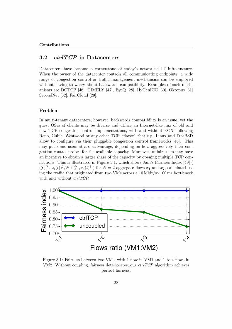
3.1 Fairness between two VMs, with 1 flow in VM1 and 1 to 4 flowsin VM2. Without coupling, fairness deteriorates; our ctrlTCP algo-rithm achieves perfect fairness. . . . . . . . . . . . . . . . . . . . . . 28
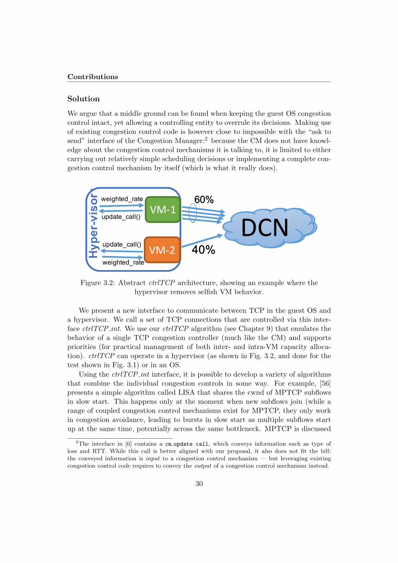
3.2 Abstract ctrlTCP architecture, showing an example where the hy-pervisor removes selfish VM behavior. . . . . . . . . . . . . . . . . . 30
5.1 Average queue length (TFRC) . . . . . . . . . . . . . . . . . . . . . . . 555.2 Average queue length (RAP) . . . . . . . . . . . . . . . . . . . . . . . . 555.3 Loss ratio (TFRC) . . . . . . . . . . . . . . . . . . . . . . . . . . . . . 555.4 Loss ratio (RAP) . . . . . . . . . . . . . . . . . . . . . . . . . . . . . . 555.5 Queue growth over time for 3 RAP flows, with FSE . . . . . . . . . . . . 555.6 Queue growth over time for 3 RAP flows, without FSE . . . . . . . . . . 555.7 Average queue length (TFRC) . . . . . . . . . . . . . . . . . . . . . . . 575.8 Average queue length (RAP) . . . . . . . . . . . . . . . . . . . . . . . . 575.9 Loss ratio (TFRC) . . . . . . . . . . . . . . . . . . . . . . . . . . . . . 585.10 Loss ratio (RAP) . . . . . . . . . . . . . . . . . . . . . . . . . . . . . . 585.11 Link Utilization (TFRC) . . . . . . . . . . . . . . . . . . . . . . . . . . 585.12 Link Utilization (RAP) . . . . . . . . . . . . . . . . . . . . . . . . . . . 585.13 Flow 1 changing its priority coupled via the FSE . . . . . . . . . . . . . 595.14 Average queue length for 10 RAP flows while changing the queue length
from 0.5 BDP(62 Packets) to 1.5 BDP (167 packets) . . . . . . . . . . . 605.15 Average queue length for 15 RAP flows while changing the queue length
from 0.5 BDP(62 Packets) to 1.5 BDP (167 packets) . . . . . . . . . . . . 605.16 Average queue length for 10 TFRC flows while changing the queue length
from 0.5 BDP(62 Packets) to 1.5 BDP (167 packets) . . . . . . . . . . . . 605.17 Average queue length for 15 TFRC flows while changing the queue length
from 0.5 BDP(62 Packets) to 1.5 BDP (167 packets) . . . . . . . . . . . . 60
xi

5.18 Loss ratio precentage as the queue length for 10 RAP flows is varied, with
and without FSE . . . . . . . . . . . . . . . . . . . . . . . . . . . . . . 61
5.19 Loss ratio precentage as the queue length for 15 RAP flows is varied, with
and without FSE, with and without FSE . . . . . . . . . . . . . . . . . 61
5.20 Fairness index as the number of TFRC flows is varied, with and without FSE 61
5.21 Fairness index as the number of RAP flows is varied, with and without FSE 61
5.22 Fairness index for 2 RAP flows as the RTT ratio is varied, with and without
FSE . . . . . . . . . . . . . . . . . . . . . . . . . . . . . . . . . . . . 62
5.23 Fairness index for 3 RAP flows as the RTT ratio is varied, with and without
FSE . . . . . . . . . . . . . . . . . . . . . . . . . . . . . . . . . . . . 62
5.24 Fairness index for 4 RAP flows as the RTT ratio is varied, with and without
FSE . . . . . . . . . . . . . . . . . . . . . . . . . . . . . . . . . . . . 62
5.25 Fairness index for 5 RAP flows as the RTT ratio is varied, with and without
FSE . . . . . . . . . . . . . . . . . . . . . . . . . . . . . . . . . . . . 62
5.26 Fairness index for 4 TFRC flows as the RTT ratio is varied, with and
without FSE . . . . . . . . . . . . . . . . . . . . . . . . . . . . . . . . 62
5.27 Fairness index for 5 TFRC flows as the RTT ratio is varied, with and
without FSE . . . . . . . . . . . . . . . . . . . . . . . . . . . . . . . . 62
5.28 Application limited flow and greedy flow – with FSE . . . . . . . . . . . 63
5.29 Application limited flow and greedy flow – without FSE . . . . . . . . . . 63
5.30 High-priority (1) application-limited flow #1 is hardly affected by a low-
priority (0.2) greedy flow #2 as long as there is enough capacity for flow
#1. . . . . . . . . . . . . . . . . . . . . . . . . . . . . . . . . . . . . . 63
5.31 Goodput of two FSE-controlled flows competing with synthetic traffic . . 64
6.1 System architecture, showing the relationship between the FSE andtwo sources, S1 and S2 . . . . . . . . . . . . . . . . . . . . . . . . . . 71
6.2 Active and Passive versions of the FSE. CC R is the rate receivedfrom the flow’s congestion controller. FSE R(f) is the rate calculatedby the FSE. Variables are explained in Section 6.3.5 and Table 6.1. . 72
6.3 Jain’s fairness index [20] for two TCP flows with heterogeneous RTTscoupled with the passive FSE. TCP’s fairness deteriorates as the flowRTT ratio decreases due to the lag in adopting the FSE assigned rate. 73
6.4 One-way delay of one NADA flow and one GCC flow across a 1 Mbps,50 ms base delay link (separate simulations). . . . . . . . . . . . . . . 74
6.5 Topology used in our experiments . . . . . . . . . . . . . . . . . . . . 77
6.6 Sending rates of 3 NADA flows and 3 GCC flows as the priorities offlows are varied at around 50 seconds. (Note that markers identifythe line and not plotted points) . . . . . . . . . . . . . . . . . . . . 79

6.7 Sending rates and delays of five NADA flows with one way delays of10 ms, 25 ms, 50 ms, 100 ms, and 150 ms. The FSE not only enforcesperfect fairness but also helps the congestion control mechanism toconverge quickly. Delay is largely unaffected. (Note that markersidentify the line and not plotted points) . . . . . . . . . . . . . . . . 79
6.8 Sending rates and delays of five GCC flows with one way delays of10 ms, 25 ms, 50 ms, 100 ms, and 150 ms. The FSE not only enforcesperfect fairness but also helps the congestion control mechanism toconverge quickly. Delay is largely unaffected. (Note that markersidentify the line and not plotted points) . . . . . . . . . . . . . . . . 80
6.9 Sending rates and delays of two continuous and one intermittentNADA flows, with and without the FSE. (Note that markers identifythe line and not plotted points) . . . . . . . . . . . . . . . . . . . . . 81
6.10 Sending rates and delays of two continuous and one intermittent GCCflows, with and without the FSE. (Note that markers identify the lineand not plotted points) . . . . . . . . . . . . . . . . . . . . . . . . . 81
6.11 Two GCC flows coupled via the FSE, where delay between stream 1and the FSE is varied based on (a) fixed delay of 50 ms (b) fixed delayof 100 ms, and (c) uniformly distributed random delay, between 1 and100 ms. . . . . . . . . . . . . . . . . . . . . . . . . . . . . . . . . . . . 82
7.1 Coupling of 3 connections when connections 2 and 3 join after 5 and6 seconds . . . . . . . . . . . . . . . . . . . . . . . . . . . . . . . . . 90
7.2 Flow completion time (FCT) of short flows. . . . . . . . . . . . . . 91
8.1 cwnd of 4 closed TCP flows . . . . . . . . . . . . . . . . . . . . . . . 97
8.2 cwnd of 4 OpenTCP flows . . . . . . . . . . . . . . . . . . . . . . . . 98
8.3 Average queue length of LEDBAT connections, with and without theOpenTCP algorithm . . . . . . . . . . . . . . . . . . . . . . . . . . . 103
8.4 Link utilization of LEDBAT connections, with and without the OpenTCPalgorithm . . . . . . . . . . . . . . . . . . . . . . . . . . . . . . . . . 103
8.5 Closed TCP: LEDBAT gets “pushed aside” . . . . . . . . . . . . . . 104
8.6 OpenTCP: TCP and LEDBAT can be fair if needed . . . . . . . . . 104
9.1 Message sequence chart of communication between a TCP sessionand the Coupled Congestion Control (CCC) entity. ∗Response is not
sent if the session is in Fast Recovery (FR) . . . . . . . . . . . . . . . . . . 113
9.2 cwnd of two TCP Reno flows . . . . . . . . . . . . . . . . . . . . . . 117
9.3 Coupling of 2 flows when flow 2 joins after 5 seconds. Packet sequenceplots and cwnd plots are shown with and without the use of ack-clocking mechanism . . . . . . . . . . . . . . . . . . . . . . . . . . . 118
9.4 Emulated testbed topology . . . . . . . . . . . . . . . . . . . . . . . 119

9.5 Throughput of 2 flows, for ctrlTCP, E-TCP, and EFCM while in-creasing the number of timeouts . . . . . . . . . . . . . . . . . . . . 120
9.6 cwnd (in Kbytes) plot of two TCP connections using coupled conges-tion control with priorities compared to a single TCP flow scenario.The aggregate line depicts the sum of cwnds in two connections sce-nario. cwnd going down all the way to 0 whenever cwnd is reduced isnot related to ctrlTCP but a result of how cwnd is internally updatedin FreeBSD. . . . . . . . . . . . . . . . . . . . . . . . . . . . . . . . . 121
9.7 Flow completion time (FCT) of short flows, with and without ack-clocking (simulation) . . . . . . . . . . . . . . . . . . . . . . . . . . . 122
9.8 Flow completion time (FCT) of short flows without ack-clocking (em-ulation) . . . . . . . . . . . . . . . . . . . . . . . . . . . . . . . . . . 123
9.9 Average delay (in milliseconds) as the number of TCP connectionsis varied, with and without coupled congestion control (emulation) . 124
9.10 Average goodput as the number of TCP connections is varied, withand without coupled congestion control (emulation) . . . . . . . . . 124
9.11 Loss ratio as the number of TCP connections is varied, with andwithout coupled congestion control (emulation) . . . . . . . . . . . . 125
9.12 Throughput ratio as the priorities of two TCP connections are varied 1259.13 Fairness between two VMs, with 1 flow in VM1 and 1 to 4 flows
in VM2. Without coupling, fairness deteriorates; our ctrlTCP algo-rithm achieves perfect fairness. . . . . . . . . . . . . . . . . . . . . . 126
9.14 Complete TCP-in-UDP header . . . . . . . . . . . . . . . . . . . . . 1289.15 Complete TCP-in-UDP SYN and SYN/ACK header . . . . . . . . . 1299.16 TiU setup TCP option . . . . . . . . . . . . . . . . . . . . . . . . . 1299.17 TCP-in-UDP Happy Eyeballs . . . . . . . . . . . . . . . . . . . . . . 131

List of Tables
3.1 Lessons learned in this dissertation . . . . . . . . . . . . . . . . . . . 27
5.1 Names of variables used in algorithms 1 and 2 . . . . . . . . . . . . . 53
6.1 Names of variables used in Algorithm 3 . . . . . . . . . . . . . . . . 77
8.1 Overview of work related to sharing congestion information, usingtwo flows as an example . . . . . . . . . . . . . . . . . . . . . . . . . 99
9.1 Names of variables used in Algorithms 5 to 7 . . . . . . . . . . . . . . . 116
xv


Part I
Overview
1


Chapter 1
Introduction
An argument is a connected series of statements intended to establisha proposition . . .Argument is an intellectual process. Contradictionis just the automatic gainsaying of anything the other person says.
Monty PythonThe Argument Sketch
1.1 Motivation
When two Internet hosts communicate, several connections may be opened in orderto exchange multiple files or streams of data or video. This could for example bethe case when a user downloads a web page containing several images and otheritems from a server, or when a user is involved in interactive real-time communica-tion using WebRTC1. These parallel connections, each having their own congestioncontrol mechanism, compete over the Internet, resulting in undefined behaviourand unwanted interference between the flows. That is, such competition can induceundesired queuing delay and losses.
Reducing latency and loss is important for applications, especially for multime-dia applications. In order to understand the magnitude of the connection competi-tion problem, we ran an ns-2 simulation where we show the increase in queue growthwith Rate Adaptation Protocol (RAP) [1]. RAP is a simple rate-based TCP-likecongestion control mechanism. Fig. 1.1 illustrates how the average queue lengthgrows as we vary the number of RAP flows.
Generally, there are two approaches to combine the connections that are knownto share a common path: by merging application layer data streams onto a sin-gle transport layer connection (SPDY [2] and HTTP/2 address this problem by
1The IETF counterpart of the W3C WebRTC standard is called RTCWEB. For simplicity, wewill use the term “WebRTC” for the whole set of standards.
3

Introduction
5
10
15
20
25
30
35
2 4 6 8 10 12 14 16 18 20
Avera
ge Q
ueue L
ength
# of Flows
Figure 1.1: Average queue length (in packets) as the number of RAP flows isvaried
multiplexing all data on one single TCP connection. Doing this at the applicationlayer leads to transport layer Head-of-Line blocking delay; this has recently beenaddressed by QUIC [3], which operates over UDP); or by combining the congestioncontrols of the connections at the transport layer. This thesis emphasizes on thelatter, which is often referred to as coupled congestion control.
To highlight the impact on the fairness between flows, we use two instancesof the open source video conferencing tool “vic”2 that we have extended to talkto a simple congestion manager using Unix domain sockets. The vic variant thatwe use includes TFRC [4] congestion control (implemented and tested by Soo-Hyun Choi for his Ph.D. thesis [5]). Our experiments are carried out with a singlephysical host, using VirtualBox with Linux for the sender, running two instancesof vic for the senders as well as a simple congestion manager, and VirtualBox withLinux for the receiver, running two instances of vic for the receivers. The twoVirtualBox instances are logically interconnected on our Mac OS X host system,and the outgoing interface of the sender is set to have a maximum rate of 1 Mbit/sand introduce a propagation delay of 50 ms using tc / netem.
Here, we present some results (see Fig. 1.2) from a test where we have configuredthe manager to let the two flows share the bandwidth equally, similar to whatTFRC would automatically converge to. we have made vic play a file (the common“foreman” test sequence), causing it to adjust the frame rate, which translates
2http://mediatools.cs.ucl.ac.uk/nets/mmedia/
4

Motivation
0
200000
400000
600000
800000
1e+06
1.2e+06
0 20 40 60 80 100 120
Se
nd
ing
ra
te (
bits/s
)
Time (s)
Process 1Process 2
(a) when TFRC congestion controls are notcoupled
0
200000
400000
600000
800000
1e+06
1.2e+06
0 20 40 60 80 100 120
Se
nd
ing
ra
te (
bits/s
)
Time (s)
Process 1Process 2
(b) when TFRC congestion controls arecoupled
Figure 1.2: Sending rates of two vic processes across a 1 Mbit/s, 50 ms link, withand without coupling
into the received video slowing down in the face of congestion. Fig. 1.2(a) showsthe sending rates of the two sender-side vic processes without the coupling, andFig. 1.2(b) shows their sending rates with the coupled congestion control.
The test ran for two minutes. Process 1 transmitted data from the start, whereasprocess 2 was started after 30 seconds and left to run for one minute. Clearly,Fig. 1.2(b) shows less rate fluctuations than Fig. 1.2(a) in the period when process 2was active. We can also see that process 2 needed no start-up phase with coupling– it directly jumped to the correct rate, determined by process 1. In doing so, italso did not have to exceed the link capacity, which created delay and eventuallycaused packet loss in the case without coupling; on average, the delay measuredwith ping was 19% higher in the case without coupling.
Almost a decade ago, there were some efforts to combine the congestion controlsof multiple TCP connections sharing the same bottleneck. To the best of ourknowledge, Congestion Manager (CM) [6] is the oldest such effort. However, it washard to implement. Ensemble TCP (E-TCP) [7] and Ensemble Flow CongestionManagement (EFCM) [8] are also two proposals along these lines; while E-TCPtried to be no more aggressive than one flow, EFCM tried to be as aggressive as nflows. Neither E-TCP nor EFCM correctly considered TCP congestion states.
All the aforementioned approaches have an additional, entirely different prob-lem: they assume that multiple TCP connections sending to the same destinationwould take the same path. This is not always true – load-balancing mechanisms suchas Equal-Cost Multi-Path (ECMP) and LAG [9] may force them to take differentpaths. Therefore, in this particular scenario, combining the congestion controllers
5

Introduction
would incur wrong behavior.
1.2 Research Questions
The aforementioned problem statement leads us to formulate the following researchquestions (RQ) that this dissertation attempts to answer.
− RQ1: Can a solution be simple and flexible enough to be gradually deployablewithout changing the underlying network?
Due to the sheer design complexity, the Congestion Manager never reachedbeyond the experimental stack albeit it is a proposed IETF standard [10]. A con-gestion management solution should be simple and flexible enough so that it cangradually be deployed in the Internet, while supporting a wide range of applications.To address this, this dissertation sets out to design a simple and flexible solution.
− RQ2: Can we always apply a solution between the same pair of hosts?
Due to mechanisms like ECMP and LAG, connections between the same pairof hosts may not share the same bottleneck. This may incur a wrong result, if,e.g., a large Initial Window (IW) from the aggregate is given to a newly joiningconnection. Are there any obvious cases where a congestion management algorithmcan be applied? We set out to explore workable solutions for this issue, therebyanswering the question when to apply such a solution.
− RQ3: Can we find a simple generic mechanism that can be applied to differentcongestion control mechanisms?
A simple sender-side congestion management algorithm cannot readily be ap-plied to different applications with different congestion control mechanisms. Forexample, a congestion control with receiver-side calculation may not react immedi-ately upon changes at the sender-side only. In this dissertation, we set out to explorehow a simple generic mechanism needs to be changed for different congestion controlmechanisms.
− RQ4: What are the potential benefits of such schemes that have not beenconsidered in the prior approaches?
As explained in the previous section, the competition between overlapping con-nections can lead to two performance issues: high latency and increased packetloss. A single congestion management instance can eliminate such competition,and allows hosts to precisely allocate the available capacity to the flows. A con-gestion management scheme can also improve the latency and reduce packet losses,
6

Research Objectives
depending on the aggression of the congestion control mechanisms. Comparativestudies are required to find the efficacy of a congestion management solution, cov-ering a wide range of tests. We set out to provide such a comparison, evaluatingthe performance impact on latency and packet loss that prior approaches have notconsidered.
1.3 Research Objectives
The overarching objective of this dissertation is to find an efficient and feasible (de-ployable) way to combine the congestion controllers of parallel connections betweenthe same pair of hosts. To achieve this, we address the research questions RQ1 -RQ4 as follows:
1. Make our design simple and flexible while minimizing the changes to theexisting mechanisms.
2. Ensure that connections take the same path.
3. Apply our solution to different congestion congestion control mechanismsranging from bulk transfer to real-time media. This lets us derive generalguidelines for applying it to congestion control mechanisms in the future.
4. Reduce overall loss and delay.
1.4 Research Methodology
Analyzing a research problem and evaluating the performance of a solution canbe performed in two different ways: (1) formal proof and mathematical modeling,and (2) event-driven simulation and real-life experimentation. This dissertationemploys the latter. To ensure the statistical significance, experiments – except forthe results of illustrative tests in the form of evolution over time – were repeatedmany times, and the details of each of the evaluation methodologies are discussedin the published works (see Section 1.5.1 and Chapters 5 to 9).
The dissertation began with an investigation of the current solution space for thecongestion control coupling. The previously proposed coupled congestion controlsolutions were reviewed. The output from this study was then used to formulatea solution to optimize the performance by eliminating the deficiencies of the priorapproaches.
7

Introduction
1.4.1 Network Simulation
The dissertation verified the solution using two simulators: Network Simulator (ns-2)3, a popular and widely-used discrete-event simulation tool used by the networkresearchers which provides substantial support for the simulation of various networkand transport protocols, and WebRTC Simulator4, an open source software packagefor real-time communication between the browsers which uses Google CongestionControl [11]. The Google implementation in the version of Chromium that was usedin this dissertation was 47.0.2494.0. Chapters 5 to 9 used ns-2 and Chapter 6 usedthe WebRTC simulator for the performance evaluations.
A wide range of transport protocols, ranging from rate-based media congestioncontrols to less-than-best-effort transport protocols, was used for the performanceevaluation. Except for GCC, ns-2 was used for all other protocols. LEDBAT[12] and NADA [13] were imported into ns-2, using the latest code (at the time ofwriting), provided by the publishers. For the evaluation of our papers in Chapters 7to 9 the Linux TCP congestion control suite was updated with the code shippedfrom Linux 3.17.4. A preprocessed version of the TMIX traffic, taken from a 60-minute trace of campus traffic at the University of North Carolina [14], was used asa cross traffic, and it can be accessed from the common TCP evaluation suite [15].
1.4.2 Real-life Experiments
The TCP solution was implemented in the FreeBSD kernel in two different ways:1) with state shared across the freely available VirtualBox5 hypervisor, and 2) asa single-OS implementation that couples connections from the same OS only. TheCommon Open Research Emulator (CORE) [16] version 4.7, a tool for emulatingnetworks on one or more machines, was used to form the topology for the ex-perimentation. To impose cross-traffic, D-ITG [17] was used to generate burstyInternet-like traffic. A more detailed explanation of CORE’s network setup in ourreal-life experiments is given in Section 9.3 of Chapter 9.
1.5 Published Works
This section describes two important contributions in this dissertation: researchpapers and Internet drafts. Section 1.5.1 provides the summaries of all the publishedresearch papers, while Section 1.5.2 provides the summaries of all the publishedInternet-Drafts.
3http://www.isi.edu/nsnam/ns/4https://webrtc.org5https://www.virtualbox.org
8

Published Works
1.5.1 Research Papers in this Thesis
Paper I (Chapter 5)
Title: Coupled Congestion Control for RTP Media
Authors: Safiqul Islam, Michael Welzl, Stein Gjessing and Naeem Khademi
Venue: ACM SIGCOMM Capacity Sharing Workshop (CSWS 2014), 18 Au-gust 2014, Chicago, USA. Also published in ACM SIGCOMM CCR 44(4), October2014.
Achievement: Best paper and presentation awards.
My Contributions: Main authorship; idea of the paper; developed all ns-2simulation scripts and codes, and conducted all simulation tests; data analysis andproducing results (e.g., graphs, figures, etc.); contributed text and editorial work.
Summary: This paper introduces a coupled congestion control mechanism forreal-time media flows that share a bottleneck. Simulations with two congestion con-trol mechanisms, Rate Adaption Protocol (RAP) and TCP Friendly Rate Control(TFRC), show its benefits in terms of precise rate allocation, reduced overall delayand losses.
Note: An extended technical report is included in this dissertation.
Paper II (Chapter 6)
Title: Managing Real-Time Media Flows through a Flow State Exchange
Authors: Safiqul Islam, Michael Welzl, David Hayes and Stein Gjessing
Venue: IEEE NOMS 2016, Istanbul, Turkey, 25-29 April 2016.
My Contributions: Main authorship; idea of the paper; developed all ns-2and Chromium simulation scripts and codes, and conducted all simulation tests;data analysis and producing results (e.g., graphs, figures, etc.); contributed textand editorial work.
Summary: Having shown in Paper I how our solution performs with the RateAdaption Protocol (RAP) and TCP Friendly Rate Control (TFRC), this paper
9

Introduction
evaluates two pertinent RMCAT congestion control mechanisms: Network-AssistedDynamic Adaptation (NADA) and Google Congestion Control (GCC). While show-ing how the solution can be adapted based on the congestion control algorithms,this paper finds that both these mechanisms exhibit aspects that allows us to use asimpler passive coupling algorithm. Passive coupling works well with relaxed timeconstrains and requires less signaling from the flows, which in turn enables the so-lution to run as a stand-alone application tool.
Paper III (Chapter 7)
Title: Start Me Up: Determining and Sharing TCP’s Initial Congestion Win-dow
Authors: Safiqul Islam and Michael Welzl
Venue: ACM, IRTF, ISOC Applied Networking Research Workshop 2016 (ANRW2016), Berlin, Germany, 16 July 2016.
My Contributions: Main authorship; idea of the paper; developed all ns-2simulation scripts and codes, and conducted all simulation tests; data analysis andproducing results (e.g., graphs, figures, etc.); contributed text and editorial work.
Summary: This paper introduces a simple method that paces packets by cor-rectly maintaining the ACK clock to distribute a large initial window to a newlyjoined flow without creating bursts in the network. Simulation results show signif-icant improvements in the completion time of short flows without incurring disad-vantages of timer-based mechanisms.
Paper IV (Chapter 8)
Title: OpenTCP: Combining Congestion Controls of Parallel TCP Connections
Authors: Safiqul Islam, Michael Welzl, Stein Gjessing and Jianjie You
Venue: IEEE IMCEC 2016, Xi’an, China, 3-5 October 2016.
Achievement: Best paper award.
My Contributions: Main authorship; idea of the paper; developed all ns-2simulation scripts and codes, and conducted all simulation tests; data analysis andproducing results (e.g., graphs, figures, etc.); contributed text and editorial work.
10

Published Works
Summary: This paper describes the requirements and design goals of imple-menting a coupled congestion control for TCP. Using ns-2 simulations, this paperreports experiments which show the benefits of combining not only the parallelLEDBAT congestion controllers, but also two different congestion control mecha-nisms: a LEDBAT and a TCP connection.
Paper V (Chapter 9)
Title: Single-Path TCP Congestion Control Coupling
Authors: Safiqul Islam, Michael Welzl, Kristian Hiorth, David Hayes, ØysteinDale, Grenville Armitage and Stein Gjessing
Venue: Under submission.
My Contributions: Main authorship; contribution to the idea of the paper;developed all ns-2 simulation scripts, codes and conducted all simulation tests;supervised two master students (Kristian Hiorth and Øystein Dale) for FreeBSDimplementation and evaluations; data analysis and producing results (e.g., graphs,figures, etc.); contributed text and editorial work.
Summary: This paper presents a method, ctrlTCP, to combine the conges-tion controls of parallel TCP connections. Using both ns-2 simulations and real-lifetests using a FreeBSD kernel implementation, this paper shows that ctrlTCP re-duces overall queuing delay and packet losses while precisely allocating the availablecapacity based on the application needs. In addition, this paper presents a simplelight-weight encapsulation method, TCP-in-UDP (TiU), to ensure the same pathby encapsulating multiple TCP connections onto a UDP port pair.
Note: An extended technical report is included in this dissertation.
1.5.2 Related Internet Drafts
Internet Draft I (Chapter 10):
Title: Coupled Congestion Control for RTP Media (draft-ietf-rmcat-coupled-cc)
11
Introduction
Authors: Safiqul Islam, Michael Welzl and Stein Gjessing
Status (at the time of writing): Active Internet draft in the IETF Real-Time Media Congestion Avoidance Techniques (RMCAT) working group; the drafthas passed the working group last call, and is currently waiting for IESG reviews.
My Contributions: Editorship; contributed text and editorial work as well asthe IETF meeting presentations and discussions.
Summary: This draft describes a simple and flexible method to combine RTPflows originating from the same sender while minimizing the amount of changesneeded to existing RTP applications. This draft specifies how this method can beapplied to two RMCAT mechanisms: NADA and GCC, and provides recommenda-tions on how to apply it to different congestion control mechanisms.
Internet Draft II (Chapter 11):
Title: TCP-CCC: Single-Path TCP Congestion Control Coupling (draft-welzl-tcp-ccc)
Authors: Michael Welzl, Safiqul Islam, Kristian Hiorth and Jianjie You
Status (at the time of writing): Active independent Internet draft undersubmission to the IRTF Internet Congestion Control Research Group (ICCRG).
My Contributions: Editorship; contributed text and editorial work as well asthe IRTF meeting presentations and discussions.
Summary: This draft presents a TCP congestion control coupling method,TCP-CCC, which not only precisely allocates the share of the available bandwidthbased on the applications’ priorities but also reduces overall delay and loss. Thisdocument highlights that connections between the same pair hosts may not traversethe same bottleneck due to load-balancing mechanisms. To address this, it presentsmethods to ensure that the connections traverse the same path.
Internet Draft III (Chapter 12):
Title: TCP Control Block Interdependence (draft-touch-tcpm-2140bis)
Authors: Joe Touch, Michael Welzl, Safiqul Islam and Jianjie You
12

Published Works
Status (at the time of writing): Active independent Internet draft undersubmission to the IETF TCPM working group.
My Contributions: Editorship; contributed text and editorial work as well asIETF meeting presentations and discussions.
Summary: This draft proposes an update of RFC2140. It discusses TCP statesharing (e.g., connection state, congestion control information), often maintained ona per-connection basis in the TCP Control Block (TCB). Some of the TCB statescan be shared to improve the overall transient transport performance, affectingonly the TCB initialization phase. This document encompasses two ways of TCBsharing:(1) Temporal Sharing—where a newly joining connection uses the cachedinfo from a closed connection; and (2) Ensemble sharing—where a newly joinedconnection is initialized using information other active concurrent connections.
1.5.3 Short Summaries / Posters (Not Included in the Thesis)
1. Safiqul Islam, Michael Welzl, Stein Gjessing: “Coupled Congestion Controlfor WebRTC”, EUCNC conference, June/July 2015, Paris, France.
2. Safiqul Islam, Michael Welzl, Stein Gjessing: “One Control to Rule Them All- Coupled Congestion Control for RTP Media”, Packet Video Workshop 2013,13 December 2013, San Jose.
13

Introduction
14

Chapter 2
Background
This section is split into three parts so that the reader is presented with nec-essary background information before delving into the details: Section 2.1 givesan overview of the congestion control mechanisms employed in this dissertation,Section 2.2 outlines previous works and recent advancements on coupled conges-tion control, and Section 2.3 introduces three different ways to detect a sharedbottleneck.
2.1 Internet Congestion Control
Congestion occurs along a path when resource demands exceed the capacity. Thegoal of Internet congestion control mechanisms is to efficiently utilize the link ca-pacity while maintaining a low loss ratio and small delay.
TCP is the predominant transport protocol on the Internet, and works well forapplications, such as bulk file transfer. TCP congestion control [18] consists of fourentwined algorithms: slow-start, congestion avoidance, fast retransmit, and fast re-covery. The first two algorithms must be used to control the amount of outstandingdata that is supposed to be injected to the network. The slow-start algorithm playstwo important roles at the beginning of the transmission: (i) probe the network ca-pacity, and (ii) start the “ack-clock” that will be used to control the data transmis-sion. Each TCP connection maintains two important state variables to regulate thesending rate, congestion window (cwnd)—this controls the number of outstandingpackets in the network; and slow-start threshold (ssthresh)—this controls whethera connection will use the slow-start or congestion avoidance algorithm.
However, window based control such as TCP is not well-suited for multimediaapplications. For such applications, rate based congestion control mechanisms, suchas Rate Adaptation Protocol (RAP) [1] and TCP-Friendly Rate Control (TFRC)
15

Background
[4, 19], are suitable because they do not stop in case of no feedback. RAP—perhapsthe oldest and first of its kind to consider TCP-friendliness and rate-based control—mimics TCP’s Additive-Increase Multiplicative-Decrease (AIMD). To govern thetime between sending two packets, it maintains a variable, the “inter-packet gap(IPG)”. On the other hand, TFRC is the only standardized congestion controlmechanism for video conferencing applications; it uses an equation to constantlyupdate its sending rate. The receiver piggybacks the necessary input parameterssuch as RTO (derived from an RTT estimate) and loss event rate (calculated at thereceiver end) that are fed to the equation in order to calculate the sending rate.
The aforementioned congestion control mechanisms are not well-suited for real-time interactive communication such as WebRTC. The “RTP Media CongestionAvoidance Techniques” (RMCAT) IETF working group has been established to de-velop suitable congestion control algorithms and a method to combine the conges-tion control mechanism to achieve a better sending rate allocation for the new We-bRTC standard, which provides interactive communication through web browsers.Three congestion control mechanisms were proposed in RMCAT: Network-AssistedDynamic Adaptation (NADA) [13, 20], Google Congestion Control (GCC) [11], andSCReAM [21]. Among all these mechanisms, only GCC has been widely deployed: itis used by Google Chrome, Chromium (an open-source version of Google Chrome),Firefox, and Opera browsers. In this dissertation, we only focus on NADA andGCC.
In NADA, a sender regulates its sending rate based on a receiver’s RTCP feed-back. That is, a receiver periodically reports implicit (one-way delay measurementsand packet drops) and explicit signals piggybacked in an RTCP feedback to a sender,where is is used to calculate the sending rate. A NADA sender uses two differentmodes to update its sending rate: (1) gradual rate update (updates rates based onthe periodic feedback); and (2) accelerated ramp up (increases rates faster whenthe reported queuing delay is close to zero).
GCC employs two methods of congestion control: (i) a loss-based controller(controls the bandwidth based on packet loss), and (ii) a delay-based controller(controls the bandwidth based on delay). Both these controllers are designed toregulate the sending rate. The loss-based controller only reacts to losses when it isover 10%.
Low Extra Delay Background Transport (LEDBAT) [12, 22] is a delay-basedexperimental congestion control mechanism where a sender calculates its sendingrate using one-way delay measurements deduced from a receiver’s acknowledgments.LEDBAT provides a less-than-best-effort (also known as “scavenger”) service for“background” applications (e.g. updates) where a strict data delivery deadline isnot required.
16

Coupled Congestion Control
2.2 Coupled Congestion Control
This section briefly outlines the prior significant attempts at single path coupledcongestion control, application layer multiplexing, data center capacity manage-ment, and coupled congestion control for multi-path TCP.
2.2.1 Single-Path Congestion Control Coupling
Here we provide an overview of the most relevant related research works, which wecategorize according to the scopes of the mechanisms.
RFC2140 - TCP Control Block Interdependence To the best of our knowl-edge, RFC2140 [23] is the first work to outline a mechanism for coupling TCPconnections by sharing TCP’s Control Block (TCB) in order to better initializenew connections. Two cases of TCB sharing were described: Temporal Sharing (aTCB of a closed connection is used to initialize a new connection), and EnsembleSharing (TCBs of active concurrent connections are used to initialize a new connec-tion). Both cases only improve the transient transport performance, and thus haveno impact on the long-term behavior of the connections. Often, connections – withdifferent 5-tuples – do not share the same path along the way due to mechanismslike ECMP and LAG [9]. However, RFC2140 assumes that connections betweenthe same host-pair traverse the same path. Hence, using an Initial Window (IW)from the shared states for a new connection, not sharing the same path, can resultin incorrect behavior and create sudden bursts in the network. Moreover, RFC2140neither mentions ssthresh sharing (which can lead to incorrect states) nor suggeststhe use of pacing to avoid sudden bursts when using a large IW.
TCP Fast Start TCP Fast Start [24] uses the concept of RFC2140 temporalsharing in order to improve the start-up performance of new connections. As men-tioned earlier, giving a large IW can potentially create bursts. To avoid this prob-lem, TCP Fast Start marks extra packets sent during the fast-start phase with ahigher-drop priority flag. However, this mechanism requires in-network support,making it difficult to deploy on the Internet.
Ensemble TCP (E-TCP) Ensemble TCP (E-TCP) [7] extended RFC2140’sTCB state sharing concept to allow concurrent flows to benefit from each other be-yond initialization, working together so that the aggregate of the parallel concurrentconnections is no more aggressive than a single TCP/Reno connection. Simulationresults showed that E-TCP improves the performance of HTTP 1.0 (where a newTCP connection is initiated to download for each and every object).
17

Background
In E-TCP, when a flow experiences a timeout, this forces all other flows to behavein a very conservative manner, i.e. going to slow-start from congestion avoidance. ARetransmission Timeout (RTO) should only occur when no more acknowledgmentsarrive (TCP has been greatly improved over the years to avoid RTOs when ACKsarrive in the Fast Recovery mode). Thus, if one connection sees no ACKs in FastRecovery, yet they do arrive for another connection, it is a mistake to force all flowsto go to slow-start. Similar to RFC2140, E-TCP also assumes that connections doshare a common bottleneck.
Ensemble Flow Congestion Management (EFCM) The Ensemble FlowCongestion Management (EFCM) [8] shares state like E-TCP but allows the ag-gregate to be collectively as aggressive as the combination of separately controlledTCP connections.
TCP operates on loss events (one or more packet losses per RTT), not indi-vidual packet losses. When congestion controls are combined, this logic should bepreserved; we explain this by assuming two connections traversing the same bottle-neck. A single packet drop from connection 1, two drops from connections 1 and2 or multiple packet drops from connection 2 only should all result in the samebehavior of the traffic aggregate. EFCM does not adopt this rationale, and there-fore flows remain aggressive when there is a drop from connection 1 because theaggregate is not halved. Simply sharing TCP variables such as cwnd or ssthreshcannot achieve this.
EFCM also has an issue of initial ssthresh sharing: a new connection joiningan aggregate with a large ssthresh value in the EFCM algorithm can potentiallycreate bursts in the network and move the ensemble from congestion avoidance intoslow-start. Similar to the aforementioned approaches, EFCM also assumes thatconnections between the same host-pair share a common bottleneck.
Congestion Manager The Congestion Manager (CM) [6, 10] takes the statesharing concept to the next level, using a generic congestion control by movingcongestion control functionalities outside of TCP connections. It provides fully dy-namic state sharing capabilities by simply maintaining all the states required toperform a congestion control mechanism in one place. It is, however, exceedinglyhard to dynamically tune (i.e., turning on/off) when connections do not share acommon bottleneck as it revamps the congestion control functionalities with a com-pletely new congestion control mechanism. CM requires explicit feedback from thereceiver’s transport protocol. However, many unreliable transport protocols do notexplicitly provide feedback to the sender. To address this, CM also suggests to sendprobe messages to actively measure congestion episodes. The deployment of CMnever reached beyond the experimental stack even though it is a proposed standard;Duke et al. state in RFC7414 [25]:
18

Coupled Congestion Control
“Although a Proposed Standard, some pieces of the Congestion Manager sup-port architecture have not been specified yet, and it has not achieved use or imple-mentation beyond experimental stacks.”
2.2.2 Multiplexing
Another method to avoid the competition of multiple flows is to merge application-layer data streams above a single transport instead of changing the congestioncontrol mechanisms to work together. This is done by SPDY [2] and HTTP/2 [26],for example; these protocols multiplex web sessions on top of a single TCP connec-tion between client and server. Multiplexing application flows onto a single TCPconnection can result in head-of-line (HoL) blocking due to TCP’s strict in-orderdata delivery. Solving HoL blocking usually involves entirely different transportprotocols, such as QUIC [3] or SCTP [27].
2.2.3 Datacenter Capacity Management
There are several efforts to fairly control and share the network capacity of completedatacenter. In EyeQ [28] bandwidth is shared and guaranteed across all users ofthe datacenter and access is controlled at the edges. To achieve fairness, FairCloud[29] uses per-flow queues in the switches and HyGenICC [30] presents a networkabstraction layer to each VM. In order to ensure that all VMs get their fair share,somewhat static allocation of bandwidth is performed by Oktopus [31] (coordinatedcentrally), SecondNet [32] (between pairs of VMs) and Gatekeeper [33].
Generally, most schemes to manage datacenter traffic operate on the data chan-nel. This has the advantage that on-host mechanisms Seawall [34] and EyeQ, forexample, can control all traffic leaving the VM, not only TCP, and apply func-tions ranging from congestion control to traffic shaping or scheduling. However, itis not uncommon for hypervisors to enable direct access to hardware drivers (e.g.VMWare’s ESXi hypervisor supports TCP Segment Offloading (TSO) for VMs),and this puts such traffic management functions on a very time-critical criticalpath.
2.2.4 Multi-Path Congestion Control Coupling
Coupled congestion control is an important part of MultiPath TCP (MPTCP) [35].There are several proposals, e.g. LIA [36, 37], OLIA [38] and BALIA [39]. Sim-ilar to E-TCP and the CM, these mechanisms try to make multiple flows behavelike a single flow when they traverse a single bottleneck (and [40] proposes to de-tect whether shared bottlenecks exist and switch behavior accordingly). However,
19

Background
MPTCP’s coupling assumes that flows could take a different path, and ideally alsotraverse different bottlenecks.
MPTCP’s subflows also use different tuples in order to be able to use differentpaths. This is exactly the opposite of what we try to achieve in this dissertation.Using a mechanism like ours in MPTCP would result in incorrect behavior. Forexample, giving a large share of the aggregate to a new connection can result inusing a very large Initial Window on an entirely different path. Similarly, changingpriorities of flows on-the-fly would be no problem with our solution, but could resultin detrimental behaviour when flows do not share a bottleneck.
2.3 Shared Bottleneck Detection
Using a coupled congestion management technique as described in this dissertationis only be appropriate when connections traverse a common bottleneck. SharedBottleneck Detection (SBD) is therefore pivotal in order to identify such connectionsand group them. There are three different ways to derive whether connections sharea bottleneck:
1. Multiplexing is considered to be a completely reliable measure to apply a con-gestion management solution. Connections having the same five-tuple ((IPsource and destination address, protocol, and transport layer port numberpair) are (supposed to be) treated the same way along the path. This classifi-cation is only applicable between the same pair of hosts, and is well suited forcertain VPN tunnels (e.g., Generic UDP Encapsulation (GUE) [41]), or RTPflows multiplexed onto a single transport protocol [42].
2. Using a system configuration can be used to decide a shared bottleneck (e.g., acommon wireless uplink). Such methods require a presumption of the networkenvironment.
3. Measurements of e.g. correlations among measured delay and loss can beused to deduce whether flows overlap in time and share a bottleneck. Thisenables to combine not only flows from the same sender and receiver but alsoflows destined for different receivers. However, this method is not completelyreliable but a recent Shared Bottleneck Detection (SBD) method [43, 44]has shown promising results. Since such methods use knowledge from thepast, they cannot be perfectly reliable. We should therefore take cautionarymeasures to dynamically enable/disable coupled congestion control. That is,coupled congestion control mechanism should be disabled if it significantlyincreases delay or loss.
20
Chapter 3
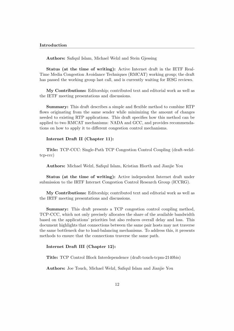
Contributions
This chapter highlights the main contributions of this work. We contribute toa better understanding of coupling congestion controls by covering a wide range ofcongestion control mechanisms used for real-time media, background-transfer, andweb-like traffic. An extensive experimentation of the proposed solution has beendone, using the following six congestion control mechanisms:
1. Rate Adaptation Protocol (RAP), a simple rate based AIMD protocol, rep-resenting a whole class of TCP-like mechanisms.
2. TCP Friendly Rate Control (TFRC), because it updates the rates based on anequation, and is currently the only standardized congestion control mechanismaimed at supporting media flows.
3. Network Assisted Dynamic Adaptation (NADA) - because it is work in progressin RMCAT.
4. Google Congestion Control (GCC), another work-in-progess congestion con-trol mechanism in RMCAT, and is currently deployed in web browsers (Chrome,Firefox).
5. Low Extra Delay Background Transport (LEDBAT) - because it is a delay-based mechanism, and very well known as a less-than-best-effort mechanismfor services such as operating system updates. A variant of LEDBAT is usedby BitTorrent.
6. Transmission Control Protocol (TCP), because it is the most widely usedtransport protocol for web-like traffic as well as bulk transfers.
From these experiments, we derive several key findings which make up the maincontributions of this dissertation.
21
Contributions
3.1 Overview of the Main Contributions
Active vs Passive: We devise a method which combines the congestion controlsof multiple RTP based real-time media flows (see Chapters 5, 6 and 10). Themethod involves a central storage element, the “Flow State Exchange (FSE)”, andcan be initiated in two ways:
1. Active FSE – initiates communication with the flows actively.
2. Passive FSE – maintains the state of the ensemble and makes it available toonly the flow requesting a new rate.
As a first step, a very simple active version of the FSE has been applied to theRAP and TFRC congestion control mechanisms where we keep track of the aggre-gate of all the flows and assign each flow a weighted proportion of the aggregate. Wehave found with simulations in Chapter 5 that the mechanism yields perfect controlover fairness, however it did not reduce overall queuing delay and loss. This, in turn,leads us to an important finding regarding synchronization and de-synchronizationof flows: since, our solution de-synchronizes the flows, a flow experiencing conges-tion and halving its rate in an ensemble of 5 flows reduces the aggregate e.g. from5Mbps to 4.5Mbps, whereas, without the coupling, they sometimes synchronize andhalve their rates as well as the aggregate. We solve the problem by extending themechanism (see Section 5.3) to emulate the behavior of one flow on congestion.
Takeaway#1 A simple active algorithm that only assigns flows a share of theaggregate without otherwise influencing their congestion control does not signifi-cantly reduce the overall delay and losses.
For a better understanding, a high-level algorithmic description of our solutionis given below:
When a f low updates ra t e :Ca l cu la t e sum of a l l r a t e s
i f ( a c t i v e ){i f ( c on s e r v a t i v e ) {
I f conge s t i on :Ca l cu la t e p r o p o r t i o n a l l y reduced ra t e f o r ALL f l owsUse a t imer to avoid over−compensation :Do not a l low other f l ows to s imu l taneous ly reducethe aggregate ra t e
}Assign a l l f l ows t h e i r share based on t h e i r p r i o r i t i e s
}e l s e // pa s s i v e
Assign f low i t s share based on i t s p r i o r i t y
22

Overview of the Main Contributions
Despite the passive version requiring less signaling and minimal changes to theflow’s congestion control, it can create problems with connections that do not up-date the rates for relatively long periods – typically because RTTs are significantlydifferent (most congestion control algorithms operate on RTT timescales). This isshown in Fig. 6.3 with TCP flows where large RTT differences delay the feedbackbetween the FSE and flows, thus preventing the solution from applying correctrates.
Takeaway#2 Both the active and passive version of the algorithms can beapplied to connections with homogeneous RTTs. However, an active version of thesolution, which triggers updates to all the flows, should be used for connections withheterogeneous RTTs. Since the update interval between the connections and thesolution can be relatively long because of significant RTT differences, the passiveversion of the algorithm should not be used.
Having applied our mechanism to RAP and TFRC, we scrutinize on applying theFSE to two proposed RMCAT congestion control mechanisms, GCC and NADA.We have shown that applying the active conservative algorithm of Chapter 5, whichemulates the behavior of one flow in the presence of congestion, can provoke NADAto trigger its “accelerated ramp-up” more often. This, in turn, makes the flowsaggressive.
Takeaway#3 Reducing the aggression of an aggregate is generally better interms of delay and loss, but it can violate the underlying CC’s assumption. Thiscan lead to undesired behaviour.
We have also found that applying the FSE to different congestion control mecha-nisms requires a small adaptation to the algorithm. In doing so, we have discoveredthat these two mechanisms exhibit aspects which lead us to an interesting find-ing: both GCC and NADA update their rates at fixed intervals—not as a functionof the RTT. Thus, we can use a simple passive version of the FSE—a less time-constrained request-response style of signaling between the FSE and the congestioncontrol mechanisms. Our evaluation covers a range of pertinent test cases [45] toshow the efficacy of applying passive coupling on NADA and GCC; results are de-tailed in Chapter 6. In addition, we show—with experiments where we have delayedthe feedback between a flow and the FSE —that this less time-constrained request-response style of signaling opens the possibilities to run the FSE as a stand-alonemanagement tool. Here is our takeaway from these tests:
Takeaway#4 A passive congestion control coupling method can be used tocombine congestions control mechanisms that update their rates at a fixed interval—not as a function of RTT (e.g., NADA, GCC). Such solution works well with relaxedtime constraints, and thus, it can run as a stand-alone management tool.
23

Contributions
Sender-Side vs Receiver-Side Congestion Control Decisions: Results fromthe active conservative version were positive for RAP, but less favorable for TFRC.This is because TFRC increases its sending rate by the deterministic length of lossintervals, calculated at the receiver side. Therefore, forcing a TFRC flow to a lowerrate than what its congestion controller has derived makes it more aggressive. Hereis our takeaway:
Takeaway#5 Any receiver-side calculation must be taken into consideration.
Stateless vs Stateful: WebRTC media flows, used in Chapters 5 and 6, arerate-based and stateless, hence it is easier to combine their congestion controlsthan with TCP. To couple TCP flows, we adopt a different design approach bycorrectly honouring the stateful nature of the TCP congestion control algorithms.We introduce ctrlTCP in Chapter 9, a minimally-invasive solution that is flexibleenough to cater for needs ranging from weighted fairness to potentially offeringInternet-wide benefits from reduced inter-flow competition.
With experimental results, we have first shown that simply sharing TCP vari-ables such as cwnd or ssthresh without taking the TCP states into consideration(as it was done in previous work) can either make an algorithm too conservative oraggressive (see Section 9.2 in Chapter 9).
We have shown the problems of not sharing states carefully using simulationswith both E-TCP (Fig. 9.2(c)) and EFCM (Fig. 9.2(b)) (see discussion related toTCP state sharing problem of E-TCP and EFCM in detail in Section 2.2.1). Tosolve this, ctrlTCP basically keeps the multiple TCP connections intact and letsthe TCP congestion controllers communicate by correctly taking the TCP states.Chapter 9 highlights how ctrlTCP is built on the state-of-the-art, and showcasesthe advantages of the solution using the ns-2 simulations and an implementation inthe FreeBSD kernel.
Takeaway#6 Whenever a congestion control mechanism is stateful (e.g., TCP,with Slow Start, Congestion Avoidance and Fast Recovery), state should also beshared to make the overall state of the aggregate correct.
We have shown that we even can control TCP connections originating fromdifferent VMs by placing our solution in a hypervisor. This allows us to take amajor step forward where our solution can be applied in multi-tenant data-centernetworks. We illustrate how a data-center network can benefit from using a coupledcongestion control mechanism in the next section.
Ensuring a Common Bottleneck: All the prior approaches in Section 2.2 as-sume that connections traverse the same path between the same pair of hosts. Inpractice, this becomes problematic due to load-balancing mechanisms like ECMP
24

Overview of the Main Contributions
and LAG. Such a case has not been considered before, and thus gives a new insight:how can we ensure that flows traverse the same path? In the course of answeringthis, we survey mechanisms that ensure the same path between the same pair ofhosts. In addition, we propose a light-weight, dynamically configured TCP-in-UDP(TiU) encapsulation scheme—several TCP connections in UDP datagrams carry-ing a single port number pair—that ensures our coupled flows do indeed share allbottlenecks along a single path. TiU is optional. Our coupled congestion controlstrategy is applicable to scenarios wherever overlapping TCP flows must follow thesame path (such as when routed over a VPN tunnel). Chapter 9 documents thestudy and our encapsulation method in detail.
Takeaway#7 Whenever connections are encapsulated or multiplexed (e.g, We-bRTC flows onto a transport protocol), a coupled congestion control mechanism canreadily be applied all along the path.
Note that this is different form of congestion control coupling than in case ofMPTCP, where the idea is that flows should take different paths. These differencesare explained in detail in Section 2.2.1.
Flow Initialization - Pacing vs No Pacing: Coupled congestion control canlet a window-based connection quickly increase its window by giving it a largeshare of the aggregate, e.g., when a connection joins, or resumes after a quiescentperiod. The crux of such sharing is that it can produce bursts and this can bemitigated using some form of pacing. We show the problem in Chapter 7. Priorapproaches use timer-based pacing which is known to have some disadvantages. Wetherefore propose a novel solution to pace the packets by correctly maintaining theACK clock instead of using a timer. This mechanism is an add-on to our ctrlTCPmechanism, but can easily be ported to better initialize new connections in orderto improve the transient performance (“temporal sharing” and “ensemble sharing”of RFC2140). Chapters 7 and 9 show its positive impact on web-like short flowswhich can complete much faster with our ctrlTCP.
Takeaway#8 Whenever a new flow joins or resumes after a quiescent period, itmay get a large share of the aggregate determined by a coupled congestion controlmechanism. In case of window-based congestion controls, this may produce a suddenburst in the network. To avoid sudden rate jumps, packets therefore should bepaced.
Combining a Heterogeneous Set of Congestion Controllers: Combining aheterogeneous set of congestion control mechanisms can yield several performancebenefits, especially when one of the mechanisms reacts on a congestion event earlierthan the others. As a first step, we have applied our solution to combine parallel
25

Contributions
LEDBAT flows, and after that, having shown our results with LEDBAT flows, wehave tested a combination of a LEDBAT and a TCP connection (see Chapter 8).This leads us to an important finding: since LEDBAT notices the increasing delay assoon as the queue grows, our solution, in fact, ensures that the queue does not groweven for TCP. This step—combining a heterogeneous set of congestion controllers—could allow to combine the WebRTC data channel and video flows (multiplexedonto a UDP port pair) that use a loss-based and a delay-based congestion controlmechanisms, respectively.
Takeaway#9 Combinations of two different congestion mechanisms can avoidbad interaction and improve the overall performance; for example, a loss-basedcontroller can benefit from a delay-based controller which reacts on a congestionepisode earlier.
Table 3.1 summarizes the major findings in this dissertation. To apply a cou-pled congestion control mechanism to a new Congestion Control (CC) mechanismthat exhibits the aforementioned aspects, the lessons learned in this work can helptowards implementing a generic coupling solution.
26

Overview of the Main Contributions
Takeaway Algorithmaspect
Recommendation
1,3 Changingalgorithmaggression
Reducing aggression can improve performance (Chapter 5),but there are exceptions: it can violate the underlying CCalgorithm’s assumption. This, in turn, can make the CCcounteract on the imposed decision (Chapters 6 and 10).
2 RTT Connections with homogeneous RTTs can use both active(Chapter 5) and passive coupling (Chapters 6, 8 and 9).However, it is recommended to use an active version forconnections with heterogeneous RTTs (Chapter 5).
4 Rate up-dates
Congestion control mechanisms that update their rates notas a function of RTTs but e.g. at a fixed interval can usesimple passive version (Chapter 6).
5 Receiver-side Logic
If the CC decisions of a connection are influenced byreceiver-side CC logic, this should be incorporated into thedesign of a coupled congestion control solution (Chapter 5).
6 Statefulness It is recommended to incorporate states in a coupling so-lution when a congestion mechanism is stateful, e.g, TCP(Chapters 8, 9 and 11). The design approaches for thestateless mechanisms are simpler (Chapters 5 and 6).
7 EnsuredCommonBottleneck
Whenever it is enforced that connections take a commonpath, e.g., connections are multiplexed (e.g., WebRTCflows) or encapsulated (e.g., VPNs), a coupled congestioncontrol mechanism can always be used (Chapters 5, 6 and 8to 11).
8 Pacing Giving a large share of the aggregate creates sudden burstsfor window based congestion control, and therefore someform of pacing is required (Chapter 7). This can beachieved with a timer or by gradually handing over theshare of the aggregate. Avoiding any increased burstinessdue to CC coupling requires an algorithm to be active.
9 CombiningDifferentCCs
Combinations of two different congestion control mecha-nisms can avoid bad interaction; for example, a loss-basedcontroller can benefit from a delay-based controller whichreacts on a congestion episode earlier (Chapter 8).
Table 3.1: Lessons learned in this dissertation
27
Contributions
3.2 ctrlTCP in Datacenters
Datacenters have become a cornerstone of today’s networked IT infrastucture.When the owner of the datacenter controls all communicating endpoints, a widerange of congestion control or traffic management mechanisms can be employedwithout having to worry about backwards compatibility. Examples of such mech-anisms are DCTCP [46], TIMELY [47], EyeQ [28], HyGenICC [30], Oktopus [31]SecondNet [32], FairCloud [29].
Problem
In multi-tenant datacenters, however, backwards compatibility is an issue, yet theguest OSes of clients may be diverse and utilize an Internet-like mix of old andnew TCP congestion control implementations, with and without ECN, followingReno, Cubic, Westwood or any other TCP “flavor” that e.g. Linux and FreeBSDallow to configure via their pluggable congestion control frameworks [48]. Thismay put some users at a disadvantage, depending on how aggressively their con-gestion control probes for the available capacity. Moreover, unfair users may havean incentive to obtain a larger share of the capacity by opening multiple TCP con-nections. This is illustrated in Figure 3.1, which shows Jain’s Fairness Index [49] ((∑N
i=1 xi(t))2/N
∑Ni=1 xi(t)
2 ) for N = 2 aggregate flows x1 and x2, calculated us-ing the traffic that originated from two VMs across a 10 Mbit/s×100 ms bottleneckwith and without ctrlTCP.
1:1 1:2 1:3 1:4
Flows ratio (VM1:VM2)
0.70
0.75
0.80
0.85
0.90
0.95
1.00
Fairn
ess
inde
x
ctrlTCPuncoupled
Figure 3.1: Fairness between two VMs, with 1 flow in VM1 and 1 to 4 flows inVM2. Without coupling, fairness deteriorates; our ctrlTCP algorithm achieves
perfect fairness.
28

ctrlTCP in Datacenters
Efforts are underway to address this problem by harmonizing the traffic comingfrom senders directly at the source; this approach has been found to have advan-tages in terms of scalability and resilience to churn over using switch and routermechanisms such as CoS tags, Weighted Fair Queuing, reservations [34]. Band-width allocation schemes in general (e.g., EyeQ [28], Gatekeeper [50], Oktopus [31],Secondnet [32], Netshare [51], FairCloud [29], Proteus [52] and Silo [53]) tend tooperate on a VM-level, making them insufficient to relieve the network of congestion[54].
Mechanisms such as Seawall [34], VCC [55] and AC/DC [54] successfully achievethis sender-side control by running dedicated congestion control algorithms as partof the hypervisor infrastructure. However, they all face a common difficulty, whichwe address in this paper: how should the new algorithm that is running as part ofthe hypervisor communicate with the the guest OS?
VCC and AC/DC do not require updating the guest OS at all, which is asignificant advantage: it does not require cooperation of tenants to update theOS (if they do bring their own OS), which reduces burden and allows to enforcecooperative behavior. However, these approaches also have disadvantages: theyhave to resort to changing the receive window (rwnd) as a means to control TCP’sbehavior.1 A sender can therefore only increase the sending rate as quickly as theTCP implementation inside the guest OS allows. A hypervisor could speed up theTCP sender inside the guest OS by splitting the TCP connection to shorten thecontrol loop, and sending ACKs faster than the real receiver; this requires managingan additional buffer inside the hypervisor, making the solution significantly morecomplex than the approach that we present in this thesis.
Seawall takes a different approach: in the guest OS, congestion control im-plementations need to defer all congestion control decisions to the hypervisor byalways asking for allowance before sending a packet [34] (similar to the CongestionManager (CM) [6, 10]). Seawall alone takes care of congestion control. Accordingto [34], the sheer performance gain should provide enough incentive for tenants toupgrade their OS; this is confirmed by some of our findings (e.g. the significantlyshorter completion times of short flows in Fig. 9.7 and 9.8). However, Seawall needsmore drastic changes to the infrastructure than e.g. VCC and AC/DC: both thesender and receiver side are altered, and bits from the header are re-purposed toimplement the necessary signaling.
1Many of the alternatives discussed in [55] have similar limitations: buffering packets or ACKs,duplicating ACKs, splitting connections, etc. The only viable alternative listed is to directly accessthe guest memory, albeit with some disadvantages as also discussed in [55].
29
Contributions
Solution
We argue that a middle ground can be found when keeping the guest OS congestioncontrol intact, yet allowing a controlling entity to overrule its decisions. Making useof existing congestion control code is however close to impossible with the “ask tosend” interface of the Congestion Manager:2 because the CM does not have knowl-edge about the congestion control mechanisms it is talking to, it is limited to eithercarrying out relatively simple scheduling decisions or implementing a complete con-gestion control mechanism by itself (which is what it really does).
VM-1
VM-2Hyper-visor
DCNweighted_rate 60%
40%weighted_rate
update_call()
update_call()
VM-1
VM-2Hyper-visor
DCNweighted_rate 60%
40%weighted_rate
update_call()
update_call()
Figure 3.2: Abstract ctrlTCP architecture, showing an example where thehypervisor removes selfish VM behavior.
We present a new interface to communicate between TCP in the guest OS anda hypervisor. We call a set of TCP connections that are controlled via this inter-face ctrlTCP int. We use our ctrlTCP algorithm (see Chapter 9) that emulates thebehavior of a single TCP congestion controller (much like the CM) and supportspriorities (for practical management of both inter- and intra-VM capacity alloca-tion). ctrlTCP can operate in a hypervisor (as shown in Fig. 3.2, and done for thetest shown in Fig. 3.1) or in an OS.
Using the ctrlTCP int interface, it is possible to develop a variety of algorithmsthat combine the individual congestion controls in some way. For example, [56]presents a simple algorithm called LISA that shares the cwnd of MPTCP subflowsin slow start. This happens only at the moment when new subflows join (while arange of coupled congestion control mechanisms exist for MPTCP, they only workin congestion avoidance, leading to bursts in slow start as multiple subflows startup at the same time, potentially across the same bottleneck. MPTCP is discussed
2The interface in [6] contains a cm update call, which conveys information such as type ofloss and RTT. While this call is better aligned with our proposal, it also does not fit the bill:the conveyed information is input to a congestion control mechanism — but leveraging existingcongestion control code requires to convey the output of a congestion control mechanism instead.
30

ctrlTCP in Datacenters
in more detail in Section 2.2.1). With ctrlTCP int, the LISA algorithm would onlyshare cwnd in the “Register” phase, provided that an existing flow in the samecoupled group is in slow start. The “Update” phase would only be used to notewhich flows have left slow start, and the “Leave” phase would remove flows fromthe list of flows the CCC keeps track off.
Implementing the CM with ctrlTCP int is also straightforward: the input fromparameters in the “register” and “update” calls could generally be ignored, and the“accept” and “response” calls would be used to dictate the cwnd that a flow shoulduse. Implementing “ask to send” would just mean that the internally-maintainedCCC cwnd value would increase or decrease as determined by the CCC logic andthen be given to TCP such that it can either send more data or not. This makesan internal variable explicitly visible to the outside, but changes nothing else.
To summarize, the required changes to TCP are:
− This function call, to be executed at the beginning of a TCP session:
register(c, P, cwnd, sshtresh); returns: cwnd, ssthresh, state
− This function call, to be executed whenever TCP newly calculates cwnd:
update(c, cwnd, sshthresh, state); returns: cwnd, ssthresh, state
− This function call, to be executed whenever a TCP session ends:
leave(c)
We have implemented our mechanism in the FreeBSD 11 kernel with state sharedacross the freely available VirtualBox3 hypervisor. Figure 3.1 was produced withthis implementation.
3https://www.virtualbox.org
31

Contributions
32

Chapter 4
Conclusions
This dissertation has proposed and evaluated a simple and flexible coupled con-gestion control solution, built on top of the state-of-the-art, to manage parallelconnections between the same host-pair. The solution has been applied to differ-ent congestion control mechanisms, and the results have shown that it can reduceoverall delay and loss.
This chapter consists of two parts: Section 4.1 addresses the research questionsstated in Section 1.2, and Section 4.2 explores the potential future directions anddeployments.
4.1 Addressing Research Questions
− RQ1: Can a solution be simple and flexible enough to be gradually deployablewithout changing the underlying network?
Simple and flexible: we have shown in Chapters 5 to 9 how our proposedsender-side solution can easily be applied to different congestion control mecha-nisms while requiring minimal changes to the existing applications. It can also bedynamically tuned when measurement based Shared Bottleneck Detection (SBD) isused. We have also identified the implication and challenges of the prior approachesand developed our solution by mitigating them.
Gradually deployable: the proposed solutions have been implemented inns-2, Chromium, and FreeBSD. Results from simulations and real-life experimentshave confirmed that our mechanism can divide the share of the available bandwidthbetween the flows based on the applications’ priorities while reducing overall delayand losses. We have also shown that our mechanism can combine connectionsoriginating not only from the same host (Chapters 5 to 9), but from different hostsusing it as a stand-alone tool (Chapter 6), and also from different virtual machines
33

Conclusions
(Chapter 9). This large variety of deployment possibilities makes it more likely thatthe mechanism can be gradually introduced into the Internet.
We conclude based on the findings from Chapters 5 to 9 that our mechanism isdeployable on the Internet without changing the underlying network.
− RQ2: Can we always apply a solution between the same pair of hosts?
Packets may not always traverse the same path due to load-balancing mecha-nisms such as ECMP and LAG. It would therefore be inappropriate for one con-nection to influence another connection that would take a different path. RQ2 hasbeen addressed with respect to detecting a shared bottleneck in Section 2.3 wherewe discuss three approaches for Shared Bottleneck Detection.
Chapters 5 and 6 conclude that the solution can always be applied to WebRTCflows which are multiplexed on a UDP port pair. In addition, Chapter 9 alsomentions several application scenarios where we can always apply our solution.To ensure the same path between the same endpoints, Chapter 9 has proposed adynamically configurable TCP-in-UDP (TiU) encapsulation scheme where severalTCP connections are encapsulated in UDP datagrams carrying a single port numberpair.
− RQ3: Can we find a simple generic mechanism that can be applied to differentcongestion control mechanisms?
RQ3 examines how hard it is to apply our solution to different congestion controlmechanisms. Our first major finding in Chapter 5 has confirmed that a simplegeneric mechanism cannot be blindly applied to a congestion control that involvesreceiver-side calculation, e.g. TFRC. Chapter 6 has used two RMCAT mechanismsto show that coupling can violate an algorithm’s underlying assumptions, requiringfurther changes to compensate for this problem.
While the congestion control mechanisms used in Chapters 5 and 6 are stateless,Chapter 9 shows that a coupled congestion control mechanism, when used with astateful congestion control mechanism such as TCP, must take states into consid-eration. We have shown the problems in Chapter 9 and built a solution upon thestate-of-the-art technologies.
Putting together, we conclude that applying a coupled congestion mechanismrequires a case-by-case analysis of the congestion control algorithm (see Table 3.1).That means, our approach is quite generic but does require small adaptations.
− RQ4: What are the potential benefits of such schemes that have not beenconsidered in the prior approaches?
RQ4 highlights the potential benefits of coupling as well as what others havenot considered in their prior approaches. Almost a decade ago, the inventors of the
34

Future Directions
prior approaches designed their coupling mechanisms considering TCP flows, notreal-time media flows. Therefore, impact on flow completion time and throughputgain was more important than reducing latency and losses. Chapters 5 to 9 haveopted for design choices which focus on precise allocation of the share of the availablebandwidth as well as reducing delay and losses.
It has been shown that simple design choices with combinations of parallel con-nections produce throughput gains by eliminating competition. Chapters 5 to 9present evaluations of our mechanism, showing a significant reduction in the queuingdelay and packet losses while precisely allocating a share of the available bandwidththat is available to a flow aggregate.
4.2 Future Directions
The dissertation has created a platform for additional research work. This sectionis split into two parts: Section 4.2.1 describes further research activities, whileSection 4.2.2 highlights the IETF activities related to deployments and proposed-standard follow-up.
4.2.1 Further Research
With measurement based SBD, it could be possible to combine connections betweendifferent host pairs. It would therefore be interesting to explore this further.
Chapter 6 has shown that our solution can work with relaxed time constraintsfor the signaling between congestion control mechanisms and the coupling entity;it could therefore be possible to use a configuration-based SBD approach where weplace our solution on a wireless access point in order to control multiple stationsassociated with it.
Preliminary results from Chapter 8 illustrate that a loss-based congestion controlmechanism can benefit from a latency-sensitive delay-based mechanism when theyare coupled together. This could allow us to combine WebRTC data and video flowssince they use a loss-based and a delay-based congestion control mechanism.
Adapting our homogeneous approach to be more or less aggressive is straightfor-ward, e.g. by changing the increase/decrease behavior as a function of the numberof flows in a coupled group similar to the way in which EFCM [8] differs fromE-TCP [7], or the way in which MulTCP [57] differs from TCP. We therefore en-courage others to develop such extensions of our algorithm in order to investigatecontrolling a larger variety of congestion control mechanisms with it.
Finally, the lessons learned in this dissertation (summarized in Table 3.1) providethe necessary information to apply our generic coupling solution to other congestioncontrol mechanisms.
35

Conclusions
4.2.2 Deployment
We have also proposed and presented our mechanism to the Internet Engineer-ing Task Force (IETF) community in order to bridge the gap between the indus-try and academia. We have actively contributed to three IETF/IRTF WorkingGroups: RTP Media Congestion Avoidance Techniques (RMCAT), Internet Con-gestion Control Research Group (ICCRG), and TCP Maintenance and Minor Ex-tensions (TCPM) as follows:
1. We have proposed our solution to the IETF RMCAT Working Group (WG)and provided necessary guidelines to the implementers on how to apply themechanisms to not only WebRTC congestion control mechanisms, NADA andGCC, but also congestion control mechanisms beyond WebRTC (see Chap-ter 10). At the time of writing, the draft has passed the WG last call, and isnow currently waiting for final reviews. Results presented in the IETF meet-ings are available in [58, 59, 60, 61, 62, 63, 64]. In addition, we have activelyparticipated in the design of the RMCAT congestion control mechanisms andits requirements.
2. Chapter 11 presents a coupled congestion control mechanism for TCP flowsalong with the ACK-Clock mechanism (Chapter 7) and TiU encapsulation(Section 9.4). This draft is currently an Active independent Internet draftunder submission to the IRTF ICCRG.
3. We have also proposed an update of RFC2140 in the IETF TCPM WG (seeChapter 12). The key changes are as follows:
(a) Text on load-balancing mechanism.
(b) Recommendations on sharing TCB states.
(c) Discusses the impact of sharing certain states (e.g., ssthresh, RTT), andalso mentions that it currently works well only for connections which areneither too short nor too long.
(d) Includes the current implementation status related to TCB sharing (Tem-poral sharing) in Linux kernel version 4.6, FreeBSD 10 and Windows (asof October 2016).
(e) Suggests using a pacing mechanism in order to avoid sudden bursts.
All these items require further contributions and participation in IETF meetingsto change:
− Change the status of draft-ietf-rmcat-coupled-cc (Chapter 10) from experi-mental to proposed standard.
36

Future Directions
− Further progress on draft-welzl-tcp-ccc (Chapter 11) in the most suitableIETF WG.
− Get draft-touch-tcpm-2140bis (Chapter 12) adopted in the IETF TCPM WG.
More standardization work beyond the three items above may be needed insupport of Internet-wide deployment of congestion control coupling—for example,to leverage encapsulation methods such as GUE [41] or ensure correct usage of theIPv6 flow label (see the discussion in Chapter 12).
37

Conclusions
38
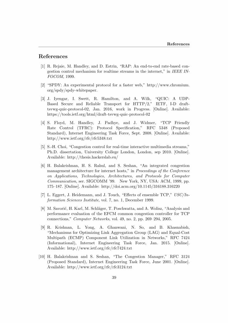
References
References
[1] R. Rejaie, M. Handley, and D. Estrin, “RAP: An end-to-end rate-based con-gestion control mechanism for realtime streams in the internet,” in IEEE IN-FOCOM, 1999.
[2] “SPDY: An experimental protocol for a faster web,” http://www.chromium.org/spdy/spdy-whitepaper.
[3] J. Iyengar, I. Swett, R. Hamilton, and A. Wilk, “QUIC: A UDP-Based Secure and Reliable Transport for HTTP/2,” IETF, I-D draft-tsvwg-quic-protocol-02, Jan. 2016, work in Progress. [Online]. Available:https://tools.ietf.org/html/draft-tsvwg-quic-protocol-02
[4] S. Floyd, M. Handley, J. Padhye, and J. Widmer, “TCP FriendlyRate Control (TFRC): Protocol Specification,” RFC 5348 (ProposedStandard), Internet Engineering Task Force, Sept. 2008. [Online]. Available:http://www.ietf.org/rfc/rfc5348.txt
[5] S.-H. Choi, “Congestion control for real-time interactive multimedia streams,”Ph.D. dissertation, University College London, London, sep 2010. [Online].Available: http://thesis.hackerslab.eu/
[6] H. Balakrishnan, H. S. Rahul, and S. Seshan, “An integrated congestionmanagement architecture for internet hosts,” in Proceedings of the Conferenceon Applications, Technologies, Architectures, and Protocols for ComputerCommunication, ser. SIGCOMM ’99. New York, NY, USA: ACM, 1999, pp.175–187. [Online]. Available: http://doi.acm.org/10.1145/316188.316220
[7] L. Eggert, J. Heidemann, and J. Touch, “Effects of ensemble TCP,” USC/In-formation Sciences Institute, vol. 7, no. 1, December 1999.
[8] M. Savoric, H. Karl, M. Schlager, T. Poschwatta, and A. Wolisz, “Analysis andperformance evaluation of the EFCM common congestion controller for TCPconnections,” Computer Networks, vol. 49, no. 2, pp. 269–294, 2005.
[9] R. Krishnan, L. Yong, A. Ghanwani, N. So, and B. Khasnabish,“Mechanisms for Optimizing Link Aggregation Group (LAG) and Equal-CostMultipath (ECMP) Component Link Utilization in Networks,” RFC 7424(Informational), Internet Engineering Task Force, Jan. 2015. [Online].Available: http://www.ietf.org/rfc/rfc7424.txt
[10] H. Balakrishnan and S. Seshan, “The Congestion Manager,” RFC 3124(Proposed Standard), Internet Engineering Task Force, June 2001. [Online].Available: http://www.ietf.org/rfc/rfc3124.txt
39

Conclusions
[11] S. Holmer, H. Lundin, G. Carlucci, L. D. Cicco, and S. Mascolo, “A googlecongestion control algorithm for real-time communication,” draft-alvestrand-rmcat-congestion-03 (work in progress), 2015.
[12] S. Shalunov, G. Hazel, J. Iyengar, and M. Kuehlewind, “Low ExtraDelay Background Transport (LEDBAT),” RFC 6817 (Experimental),Internet Engineering Task Force, Dec. 2012. [Online]. Available: http://www.ietf.org/rfc/rfc6817.txt
[13] X. Zhu, R. Pan, M. A. Ramalho, S. Mena, C. Ganzhorn, P. E. Jones, and S. D.Aronco, “NADA: A unified congestion control scheme for real-time media,”draft-ietf-rmcat-nada-00 (work in progress), 2015.
[14] M. C. Weigle, P. Adurthi, F. Hernandez-Campos, K. Jeffay, and F. D. Smith,“Tmix: A tool for generating realistic TCP application workloads in ns-2,”SIGCOMM Comput. Commun. Rev., vol. 36, no. 3, pp. 65–76, July 2006.[Online]. Available: http://doi.acm.org/10.1145/1140086.1140094
[15] L. Andrew, S. Floyd, and G. Wang, “Common TCP Evaluation Suite,” IETF,Internet-Draft draft-irtf-tmrg-tests-02, July 2009, work in Progress. [Online].Available: https://tools.ietf.org/html/draft-irtf-tmrg-tests-02
[16] J. Ahrenholz, C. Danilov, T. R. Henderson, and J. H. Kim, “Core: A real-timenetwork emulator,” in Military Communications Conference, 2008. MILCOM2008. IEEE. IEEE, 2008, pp. 1–7.
[17] A. Botta, A. Dainotti, and A. Pescape, “A tool for the generation of realisticnetwork workload for emerging networking scenarios,” Computer Networks,vol. 56, no. 15, pp. 3531–3547, 2012.
[18] M. Allman, V. Paxson, and E. Blanton, “TCP Congestion Control,” RFC5681 (Draft Standard), Internet Engineering Task Force, Sept. 2009. [Online].Available: http://www.ietf.org/rfc/rfc5681.txt
[19] S. Floyd, M. Handley, J. Padhye, and J. Widmer, “Equation-based congestioncontrol for unicast applications,” in ACM SIGCOMM, 2000. [Online].Available: http://doi.acm.org/10.1145/347059.347397
[20] X. Zhu and R. Pan, “NADA: A unified congestion control scheme for low-latency interactive video,” in Packet Video Workshop (PV), 2013 20th Inter-national. IEEE, 2013, pp. 1–8.
[21] I. Johansson and Z. Sarker, “Self-clocked rate adaptation for multimedia,”draft-ietf-rmcat-scream-cc-01 (work in progress), 2015.
40

References
[22] D. Ros and M. Welzl, “Less-than-best-effort service: A survey of end-to-endapproaches,” Communications Surveys Tutorials, IEEE, vol. 15, no. 2, pp.898–908, 2013.
[23] J. Touch, “TCP Control Block Interdependence,” RFC 2140 (Informational),Internet Engineering Task Force, Apr. 1997. [Online]. Available: http://www.ietf.org/rfc/rfc2140.txt
[24] V. N. Padmanabhan and R. H. Katz, “TCP fast start: A technique for speedingup web transfers,” 1998.
[25] M. Duke, R. Braden, W. Eddy, E. Blanton, and A. Zimmermann, “A Roadmapfor Transmission Control Protocol (TCP) Specification Documents,” RFC7414 (Informational), Internet Engineering Task Force, Feb. 2015, updated byRFC 7805. [Online]. Available: http://www.ietf.org/rfc/rfc7414.txt
[26] M. Belshe, R. Peon, and M. Thomson, “Hypertext Transfer Protocol Version2 (HTTP/2),” RFC 7540 (Proposed Standard), Internet Engineering TaskForce, May 2015. [Online]. Available: http://www.ietf.org/rfc/rfc7540.txt
[27] L. Ong and J. Yoakum, “An Introduction to the Stream Control TransmissionProtocol (SCTP),” RFC 3286 (Informational), Internet Engineering TaskForce, May 2002. [Online]. Available: http://www.ietf.org/rfc/rfc3286.txt
[28] V. Jeyakumar, M. Alizadeh, D. Mazieres, B. Prabhakar, A. Greenberg, andC. Kim, “EyeQ: practical network performance isolation at the edge,” in Pre-sented as part of the 10th USENIX Symposium on Networked Systems Designand Implementation (NSDI 13), 2013, pp. 297–311.
[29] L. Popa, G. Kumar, M. Chowdhury, A. Krishnamurthy, S. Ratnasamy,and I. Stoica, “FairCloud: Sharing the network in cloud computing,”in Proceedings of the ACM SIGCOMM 2012 Conference on Applications,Technologies, Architectures, and Protocols for Computer Communication, ser.SIGCOMM ’12. New York, NY, USA: ACM, 2012, pp. 187–198. [Online].Available: http://doi.acm.org/10.1145/2342356.2342396
[30] A. M. Abdelmoniem, B. Bensaou, and A. J. Abu, “HyGenICC: Hypervisor-based generic IP congestion control for virtualized data centers,” in 2016 IEEEInternational Conference on Communications (ICC), May 2016, pp. 1–6.
[31] H. Ballani, P. Costa, T. Karagiannis, and A. Rowstron, “Towards predictabledatacenter networks,” in Proceedings of the ACM SIGCOMM 2011 Conference,ser. SIGCOMM ’11. New York, NY, USA: ACM, 2011, pp. 242–253. [Online].Available: http://doi.acm.org/10.1145/2018436.2018465
41

Conclusions
[32] C. Guo, G. Lu, H. J. Wang, S. Yang, C. Kong, P. Sun, W. Wu, andY. Zhang, “SecondNet: A data center network virtualization architecture withbandwidth guarantees,” in Proceedings of the 6th International Conference,ser. Co-NEXT ’10. New York, NY, USA: ACM, 2010, pp. 15:1–15:12.[Online]. Available: http://doi.acm.org/10.1145/1921168.1921188
[33] H. Rodrigues, J. R. Santos, Y. Turner, P. Soares, and D. Guedes, “Gatekeeper:Supporting bandwidth guarantees for multi-tenant datacenter networks,” inProceedings of the 3rd Conference on I/O Virtualization, ser. WIOV’11.Berkeley, CA, USA: USENIX Association, 2011, pp. 6–6. [Online]. Available:http://dl.acm.org/citation.cfm?id=2001555.2001561
[34] A. Shieh, S. Kandula, A. Greenberg, C. Kim, and B. Saha, “Sharing thedata center network,” in Proceedings of the 8th USENIX Conference onNetworked Systems Design and Implementation, ser. NSDI’11. Berkeley,CA, USA: USENIX Association, 2011, pp. 309–322. [Online]. Available:http://dl.acm.org/citation.cfm?id=1972457.1972489
[35] C. Raiciu, C. Paasch, S. Barre, A. Ford, M. Honda, F. Duchene,O. Bonaventure, and M. Handley, “How hard can it be? designingand implementing a deployable multipath TCP,” in Proceedings of the 9thUSENIX Conference on Networked Systems Design and Implementation,ser. NSDI’12. Berkeley, CA, USA: USENIX Association, 2012, pp. 29–29.[Online]. Available: http://dl.acm.org/citation.cfm?id=2228298.2228338
[36] H. Li, R. Zheng, and A. Farrel, “Multi-Segment Pseudowires in PassiveOptical Networks,” RFC 6456 (Informational), Internet Engineering TaskForce, Nov. 2011. [Online]. Available: http://www.ietf.org/rfc/rfc6456.txt
[37] D. Wischik, C. Raiciu, A. Greenhalgh, and M. Handley, “Design,implementation and evaluation of congestion control for multipath TCP,” inProceedings of the 8th USENIX Conference on Networked Systems Design andImplementation, ser. NSDI’11. Berkeley, CA, USA: USENIX Association,2011, pp. 99–112. [Online]. Available: http://dl.acm.org/citation.cfm?id=1972457.1972468
[38] R. Khalili, N. Gast, M. Popovic, U. Upadhyay, and J.-Y. Le Boudec,“MPTCP is not pareto-optimal: Performance issues and a possiblesolution,” in Proceedings of the 8th International Conference on EmergingNetworking Experiments and Technologies, ser. CoNEXT ’12. NewYork, NY, USA: ACM, 2012, pp. 1–12. [Online]. Available: http://doi.acm.org/10.1145/2413176.2413178
42

References
[39] Q. Peng, A. Walid, J. Hwang, and S. H. Low, “Multipath TCP: Analysis, de-sign, and implementation,” IEEE/ACM Transactions on Networking, vol. 24,no. 1, pp. 596–609, Feb 2016.
[40] S. Ferlin, . Alay, T. Dreibholz, D. A. Hayes, and M. Welzl, “Revisiting con-gestion control for multipath TCP with shared bottleneck detection,” in IEEEINFOCOM 2016 - The 35th Annual IEEE International Conference on Com-puter Communications, April 2016, pp. 1–9.
[41] T. Herbert, L. Yong, and O. Zia, “Generic UDP Encapsulation,”Internet Engineering Task Force, Internet-Draft draft-ietf-nvo3-gue-02, Dec.2015, work in Progress. [Online]. Available: https://tools.ietf.org/html/draft-ietf-nvo3-gue-02
[42] M. Westerlund and D. C. Perkins, “Multiplexing Multiple RTP Ses-sions onto a Single Lower-Layer Transport,” Internet EngineeringTask Force, Internet-Draft draft-westerlund-avtcore-transport-multiplexing-07, Oct. 2013, work in Progress. [Online]. Available: https://tools.ietf.org/html/draft-westerlund-avtcore-transport-multiplexing-07
[43] D. A. Hayes, S. Ferlin, and M. Welzl, “Practical passive shared bottleneckdetection using shape summary statistics,” in 2014 IEEE 39th Conference onLocal Computer Networks (LCN). IEEE, 2014, pp. 150–158.
[44] D. Hayes, S. Ferlin, and M. Welzl, “Shared bottleneck detection forcoupled congestion control for RTP media,” Internet Draft draft-ietf-rmcat-sbd, work in progress, May 2015. [Online]. Available: http://tools.ietf.org/html/draft-ietf-rmcat-sbd
[45] Z. Sarker, V. Singh, X. Zhu, and M. A. Ramalho, “Test cases for evaluatingRMCAT proposals,” draft-ietf-rmcat-eval-test-01 (work in progress), 2015.
[46] M. Alizadeh, A. Greenberg, D. A. Maltz, J. Padhye, P. Patel, B. Prabhakar,S. Sengupta, and M. Sridharan, “Data Center TCP (DCTCP),” inProceedings of the ACM SIGCOMM 2010 Conference, ser. SIGCOMM’10. New York, NY, USA: ACM, 2010, pp. 63–74. [Online]. Available:http://doi.acm.org/10.1145/1851182.1851192
[47] R. Mittal, V. T. Lam, N. Dukkipati, E. Blem, H. Wassel, M. Ghobadi,A. Vahdat, Y. Wang, D. Wetherall, and D. Zats, “TIMELY: RTT-basedcongestion control for the datacenter,” SIGCOMM Comput. Commun.Rev., vol. 45, no. 4, pp. 537–550, Aug. 2015. [Online]. Available:http://doi.acm.org/10.1145/2829988.2787510
43

Conclusions
[48] A. Afanasyev, N. Tilley, P. Reiher, and L. Kleinrock, “Host-to-host congestioncontrol for TCP,” Commun. Surveys Tuts., vol. 12, no. 3, pp. 304–342, July2010. [Online]. Available: http://dx.doi.org/10.1109/SURV.2010.042710.00114
[49] R. Jain, D. Chiu, and W. Hawe, “A Quantitative Measure of Fairness andDiscrimination for Resource Allocation in Shared Computer Systems,” DECResearch, Technical report TR-301, Sept. 1984.
[50] H. Rodrigues, J. R. Santos, Y. Turner, P. Soares, and D. Guedes, “Gatekeeper:Supporting bandwidth guarantees for multi-tenant datacenter networks.” inWIOV, 2011.
[51] V. T. Lam, S. Radhakrishnan, R. Pan, A. Vahdat, and G. Varghese, “Netshareand stochastic Netshare: Predictable bandwidth allocation for data centers,”SIGCOMM Comput. Commun. Rev., vol. 42, no. 3, pp. 5–11, June 2012.[Online]. Available: http://doi.acm.org/10.1145/2317307.2317309
[52] D. Xie, N. Ding, Y. C. Hu, and R. Kompella, “The only constant ischange: Incorporating time-varying network reservations in data centers,”in Proceedings of the ACM SIGCOMM 2012 Conference on Applications,Technologies, Architectures, and Protocols for Computer Communication, ser.SIGCOMM ’12. New York, NY, USA: ACM, 2012, pp. 199–210. [Online].Available: http://doi.acm.org/10.1145/2342356.2342397
[53] K. Jang, J. Sherry, H. Ballani, and T. Moncaster, “Silo: Predictablemessage latency in the cloud,” in Proceedings of the 2015 ACM Conferenceon Special Interest Group on Data Communication, ser. SIGCOMM ’15.New York, NY, USA: ACM, 2015, pp. 435–448. [Online]. Available:http://doi.acm.org/10.1145/2785956.2787479
[54] K. He, E. Rozner, K. Agarwal, Y. J. Gu, W. Felter, J. Carter, and A. Akella,“AC/DC TCP: Virtual congestion control enforcement for datacenternetworks,” in Proceedings of the 2016 Conference on ACM SIGCOMM 2016Conference, ser. SIGCOMM ’16. New York, NY, USA: ACM, 2016, pp.244–257. [Online]. Available: http://doi.acm.org/10.1145/2934872.2934903
[55] B. Cronkite-Ratcliff, A. Bergman, S. Vargaftik, M. Ravi, N. McKeown,I. Abraham, and I. Keslassy, “Virtualized congestion control,” in Proceedingsof the 2016 Conference on ACM SIGCOMM 2016 Conference, ser. SIGCOMM’16. New York, NY, USA: ACM, 2016, pp. 230–243. [Online]. Available:http://doi.acm.org/10.1145/2934872.2934889
[56] R. Barik, M. Welzl, S. Ferlin, and O. Alay, “LISA: A linked slow-start algo-rithm for MPTCP,” in 2016 IEEE International Conference on Communica-tions (ICC), May 2016, pp. 1–7.
44
References
[57] J. Crowcroft and P. Oechslin, “Differentiated end-to-end internet servicesusing a weighted proportional fair sharing TCP,” SIGCOMM Comput.Commun. Rev., vol. 28, no. 3, pp. 53–69, July 1998. [Online]. Available:http://doi.acm.org/10.1145/293927.293930
[58] S. Islam, “Updates on coupled congestion control for RTP media,” IETF87, Berlin, Germany, 2013. [Online]. Available: https://www.ietf.org/proceedings/87/slides/slides-87-rmcat-2.pdf
[59] M. Welzl, “Updates on coupled congestion control for RTP media,” IETF 90,Toronto, Canada, 2014. [Online]. Available: http://www.ietf.org/proceedings/90/slides/slides-90-rmcat-0.pdf
[60] S. Islam, “Updates on coupled congestion control for RTP media,” IETF 91,Honolulu, USA, 2014. [Online]. Available: https://www.ietf.org/proceedings/91/slides/slides-91-rmcat-3.pdf
[61] M. Welzl, “Updates on coupled congestion control for RTP media,” IETF 92,Dallas, USA, 2015. [Online]. Available: http://www.ietf.org/proceedings/92/slides/slides-92-rmcat-1.pptx
[62] S. Islam, “Presentation on coupled congestion control for RTP media,” IETF93, Prague, 2015. [Online]. Available: http://www.ietf.org/proceedings/93/slides/slides-93-rmcat-3.pptx
[63] S. Islam, “Presentation on coupled congestion control with GCC forRTP media,” IETF 94, Yokohama, 2015. [Online]. Available: http://www.ietf.org/proceedings/94/slides/slides-94-rmcat-5.pdf
[64] S. Islam, “Updates on coupled congestion control for RTP media,”IETF 95, Buenos Aires, Argentina, 2016. [Online]. Available: https://www.ietf.org/proceedings/95/slides/slides-95-rmcat-6.pdf
45

Conclusions
46

Part II
Research Papers
47


Chapter 5
Coupled Congestion Control forRTP Media
Authors. Safiqul Islam, Michael Welzl, Stein Gjessing, and Naeem Khademi
Affiliation. Department of Informatics, University of Oslo, Norway{safiquli, michawe, steing, naeemk}@ifi.uio.no
Publication. ACM SIGCOMM Capacity Sharing Workshop (CSWS 2014),Chicago, USA, August 2014, also published in ACM SIGCOMM Computer Com-munication Review 44(4), October 2014.
Abstract. Congestion occurs at a bottleneck along an Internet path; multipleflows between the same sender and receiver pairs can benefit from using only a singlecongestion control instance when they share the same bottleneck. These benefitsinclude the ability to control the rate allocation between flows and reduced overalldelay (multiple congestion control instances cause more queuing delay than onesince each has no knowledge of the congestion episodes experienced by the others).We present a mechanism for coupling congestion control for real-time media andshow its benefits by coupling multiple congestion controlled flows that share thesame bottleneck.
5.1 Introduction
Multiple congestion controlled flows (e.g., TCP) between the same two hosts usuallyhave separate congestion control instances, even when the path used by them is thesame. There may be several reasons for this separation. For example, one cannotalways be sure if the path is indeed the same – routing mechanisms like Equal-Cost
49

Coupled Congestion Control for RTP Media
Multi-Path (ECMP) may assign different flows to different paths to achieve loadbalancing, even when they have the same destination IP address.
Routers or other middle-boxes usually identify flows using a five-tuple of sourceand destination IP addresses, transport protocol, and the transport protocol’ssource and destination port numbers. When – as it will be possible with the newWebRTC standard for interactive communication between web browsers – multipleflows are multiplexed over a single UDP port pair, they are normally regarded asa single flow inside the network and therefore treated in the same way. In such asetup, congestion management can be readily applied.
The new “RTP Media Congestion Avoidance Techniques” (RMCAT) IETFWorking Group develops standards for RTP-based interactive real-time media. We-bRTC being the major use case for these standards, RMCAT will also standardizemethods for coupled congestion control, with the goal of having the best possiblecontrol over the send rate allocation. Here, we describe the first proposal for RM-CAT’s coupled congestion control and show its feasibility and some of its benefits.
After a review of related work in the next section, we will introduce our methodfor coupling congestion control in RMCAT in Section 5.3. In Section 5.4, we showsome performance evaluation results using ns-2 simulations, and Section 5.5 con-cludes the paper.
5.2 Related Work
The Congestion Manager (CM) [1] is the best known, and perhaps the oldest relatedwork. It provides a common congestion management framework for all the flowsfrom a sender going to the same receiver. Flows pass information to the CM whichuses a scheduler to distribute the available bandwidth. Since the CM replaces eachflow’s congestion controller with an overarching one, it is hard to implement, whichmay be the reason why it has never been widely deployed.
In any standard TCP implementation, each connection maintains state (e.g. thecurrent round-trip time (RTT) and congestion window (cwnd)) in a data structurecalled Transport Control Block (TCB). RFC 2140 [2] describes that TCB datacan be shared among multiple connections in two ways: 1) Temporal Sharing, and2) Ensemble Sharing. Temporal Sharing can be used to cache state of a closedconnection, and this previous connection state can be used to later instantiatea similar connection and avoid inefficiencies. Ensemble Sharing occurs when anactive host opens another concurrent connection. Among other variables, RFC 2140discusses how cwnd can be shared in order to couple the congestion control ofmultiple flows.
Ensemble TCP (E-TCP) [3] utilizes the concept of TCB information reusing andsharing among existing connections. It has been designed to show the aggregatenetwork transmission behavior of an ensemble (parallel TCP connections) as a single
50

The Flow State Exchange
TCP/Reno connection. The authors of [3] compared it with persistent HTTP 1.1,showing benefits. E-TCP does not discuss what RFC 2140 calls Temporal Sharing,i.e. reusing cached information when the network is idle because network propertiesmight change during an idle period.
Based on E-TCP, Savoric et al. [4] proposed an Ensemble Flow Control Mech-anism (EFCM) where a controller actively probes for information from the flows,and calculates the new rate for a flow by aggregating congestion properties (e.g.RTT, cwnd). They showed that EFCM increases the throughput and fairness forthe flows sharing the same bottleneck.
Both E-TCP and EFCM are similar in style to the mechanism presented inthis paper. However, there are some important differences: these mechanisms focusexclusively on TCP congestion control, which is window based, whereas our mecha-nism targets rate-based RTP applications. Neither [3] nor [4] present an evaluationof the mechanism’s impact on queuing delay or packet loss; reducing both is animportant goal for us (RMCAT targets low-latency interactive applications). Sincewe tried to minimize changes needed to existing congestion controls, we only sharerates between flows, whereas E-TCP and EFCM share not only cwnd but also otherTCP-specific information such as SRTT and ssthresh.
Rather than trying to directly combine the congestion control of multiple flows, asimilar behavior can also be attained by multiplexing application-level data streamsonto a single connection. This can be done using e.g. SCTP, where it can lead toa significant performance benefit [5]. In [6], a performance gain was attained bytransparently mapping TCP connections onto a single SCTP association. Connec-tion reuse – with the goal of allowing TCP’s congestion window to grow largerand reduce transport-layer overhead – can also be implemented at the applicationlayer, e.g. via persistent HTTP 1.1. However, HTTP 1.1 only allows delivery ofapplication-level streams in the sequence in which they were requested, which cancause Head-Of-Line (HOL) blocking, e.g. when the first request involves a slowdatabase access. This has recently been addressed by SPDY, which multiplexesdata streams onto a single TCP connection [7].
5.3 The Flow State Exchange
RMCAT’s congestion control should be applicable but not limited to WebRTC.This means that we may need to jointly control flows that reside within a singleapplication (a web browser, in case of WebRTC) or in multiple applications. In thelatter case, WebRTC’s benefit of knowing that packets from multiple flows will berouted in the same way is lost. There are, however, measurement based methodsto determine whether multiple flows share a bottleneck in the network; being ableto make use of measurements when necessary, and supporting various intra- as wellas inter-application scenarios calls for a congestion management architecture that
51
Coupled Congestion Control for RTP Media
is much simpler than, e.g., the well-known CM.
We have opted for an approach [8] that minimizes the amount of necessarychanges to existing applications. It involves a central storage element called “FlowState Exchange” (FSE). The elements of our architecture for coupled congestioncontrol are: the Flow State Exchange (FSE), Shared Bottleneck Detection (SBD)and Flows. The FSE is a storage element that can be implemented in two ways:active and passive. In the active version, it initiates communication with flowsand SBD. However, in the passive version, it does not actively initiate communica-tion with flows and SBD, and its only task is internal state maintenance (e.g., animplementation could use soft state to remove a flow’s data after long periods ofinactivity).
Every time a flow’s congestion control mechanism would normally update itssending rate, the flow instead updates information in the FSE and performs a queryon the FSE, leading to a sending rate that can be different from what the conges-tion controller originally determined. In the active version, the FSE additionallycalculates the rates for all the other flows in the same Flow Group (FG) and ac-tively informs their congestion controllers with a callback function. A Flow Groupconsists of flows which should be controlled together, i.e. they have a common net-work bottleneck. A FG is determined by an SBD module based on measurementsor knowledge about multiplexing. An SBD module can be a part of one of theapplications using the FSE, or it can be a standalone entity. We plan to developa measurement-based SBD as future work; in this paper, we assume that FGs areknown by multiplexing flows over the same UDP port pair in WebRTC.
The FSE contains a list of all flows that have registered with it. For each flow,it stores:
1. A unique flow number to identify the flow
2. The Flow Group Identifier (FGI) of the FG that it belongs to
3. A priority P, which here is assumed to be represented as a floating pointnumber in the range from 0.1 (unimportant) to 1 (very important)
4. The calculated rate FSE R, i.e. the rate that was most recently calculated bythe flow’s congestion controller
Flows register themselves with SBD and FSE when they start, deregister fromthe FSE when they stop, and carry out an UPDATE function call every time theircongestion controller calculates a new sending rate. Via UPDATE, they providethe newly calculated rate. The FSE then calculates rates for all the flows andsends them back. When a flow f starts, FSE R is initialized with the congestioncontroller’s initial rate. SBD will assign the correct FGI. When a flow is assigned
52

The Flow State Exchange
an FGI, it adds its FSE R to S CR. When a flow stops, its entry is removed fromthe list.
As a first step, we designed Algorithm 1, which simply keeps track of the totalrate of all flows and assigns each flow a share that is weighted by the flow’s priority.Variables are explained in Table 5.1. Intuitively, it might seem that this simplealgorithm would perform well, but our initial tests have shown that it is in factunsatisfactory. Before we proceed to an improved version of the algorithm, we nowillustrate the problem with some of our intermediate results.
Variables DescriptionCC R The rate received from flow’s congestion controller when a
flow calls UPDATEnew DR The desired rate received a flow when it calls UPDATEFSE R The calculated rate by the FSES CR The sum of the calculated rates of all flows in the same FG;
this value is used to calculate the sending rateFG A group of flows having the same FGI, and hence sharing
the same bottleneckP The priority of a flow which is received from the flow’s con-
gestion controller; the FSE uses this variable for calculatingFSE R
S P The sum of all the prioritiesDELTA This is used to calculate the difference between CC R and
previously stored FSE R
Table 5.1: Names of variables used in algorithms 1 and 2
Algorithm 1 Active FSE Rate Control
Input: CC R and new DROutput: FSE R1: S P ← 02: S CR← S CR+ CC R− FSE R(f)3: FSE R(f)← CC R4: for all flows i in FG do5: S P = S P + P (i)6: end for7: for all flows i in FG do8: FSE R(i)← min(new DR, ((P (i) ∗ S CR)/S P ))9: send FSE R(i) to the flow i
10: end for
We implemented the FSE in ns-2 and simulated the behavior of congestion con-trolled flows using a dumbbell network topology (bottleneck capacity 10 Mbit/s,
53

Coupled Congestion Control for RTP Media
RTT 10 ms, packet size 1000 bytes, queue length of 13 packets1; for simplicity, un-less otherwise mentioned, senders always had enough data to send.2 The currentimplementation only supports two rate-based protocols: Rate Adaptation Protocol(RAP) [10] (because it is a simple rate-based Additive Increase – Multiplicative De-crease (AIMD) scheme, hence representing a whole class of TCP-like mechanisms)and TCP Friendly Rate Control (TFRC) [11] (because it is the only standardizedcongestion control mechanism aimed at supporting media flows).
Jain’s fairness index is used to calculate the expected gains in fairness wherea fairness index of 1 denotes that all n concurrent flows get a fair share of thetotal available bandwidth whereas a fairness index of 1/n means that one of the nflows gets the entire available bandwidth. It is clear from the algorithm, and wasalso confirmed in our simulations, that the FSE achieves precise fairness among theflows. This is important, as it is a requirement for WebRTC [12] – but becausecoupling congestion controllers should help avoid competition at the bottleneck, weexpected reduced queuing delay and packet loss, while achieving at least as muchthroughput as of a single flow. While the latter requirement was also fulfilled bythis algorithm, the results with Algorithm 1 were disappointing regarding queuingdelay and packet loss.
The loss ratio and average queue length with FSE-controlled vs. non-FSE-controlled RAP and TFRC flows are illustrated in Figures 5.1, 5.2, 5.3, and 5.4.Since we only highlight a problem, every data point in these graphs is the result ofa single simulation run. It can be seen that, with the FSE, the loss ratio improvesas the number of flows grows, but the average queue length is higher. Results wereeven worse with TFRC.
To address these problems, we investigated the queue growth over time with andwithout the FSE. As shown in Figure 5.5, the queue essentially oscillates betweenempty and full, but it does not always drain. In the same test without the FSE(see Figure 5.6), the queue failed to drain only once, in contrast to the 7 suchoccurrences in Figure 5.5. This is because the FSE de-synchronizes the flows. Forexample, consider two RAP flows, each sending at a rate X. If one of these flowstries to increase its rate and immediately experiences congestion, it halves its rate,which reduces the aggregate rate from 2X to 1.5X. However, without the FSE,when the two flows get synchronized, both halve their rate when congestion occurswhich also halves the rate of the aggregate. Synchronization is usually regarded as
1This is based on the bandwidth×delay product (BDP). We repeated our tests with differentqueue lengths and found no significant differences.
2This may not be a totally unreasonable assumption for modern multimedia systems, whichmay be able to closely track the available bandwidth (cf. [9]). However, the actual behavior iscodec-dependent and hard to characterize. At the time of writing, the RMCAT group is workingon suitable test cases; in the absence of a solution in this space, we opted to investigate two extremeends of the spectrum – the case where applications can always send data, and the case where acodec cannot adapt to the available bandwidth at all (Section 5.4).
54

The Flow State Exchange
7.5
8
8.5
9
9.5
10
10.5
11
2 4 6 8 10 12 14 16 18 20
Ave
rag
e Q
ue
ue
Le
ng
th
Number of Flows
FSEWithout FSE
Figure 5.1: Average queue length (TFRC)
5
6
7
8
9
10
11
12
2 4 6 8 10 12 14 16 18 20
Ave
rag
e Q
ue
ue
Le
ng
th
Number of Flows
FSEWithout FSE
Figure 5.2: Average queue length (RAP)
0
2
4
6
8
10
12
14
2 4 6 8 10 12 14 16 18 20
Pa
cke
t L
oss R
atio
%
Number of Flows
FSEWithout FSE
Figure 5.3: Loss ratio (TFRC)
5
10
15
20
25
30
35
40
45
2 4 6 8 10 12 14 16 18 20
Pa
cke
t L
oss R
atio
%
Number of Flows
FSEWithout FSE
Figure 5.4: Loss ratio (RAP)
a detrimental network effect, but in this case, it appears to play out positively.
0
2
4
6
8
10
12
14
15 15.5 16 16.5 17 17.5 18 18.5 19
Qu
eu
e s
ize
(p
kts
)
Time (s)
Figure 5.5: Queue growth over time for 3RAP flows, with FSE
0
2
4
6
8
10
12
14
15 15.5 16 16.5 17 17.5 18 18.5 19
Qu
eu
e s
ize
(p
kts
)
Time (s)
Figure 5.6: Queue growth over time for 3RAP flows, without FSE
In order to fix the loss ratio and average queue growth, we updated our algorithm
55
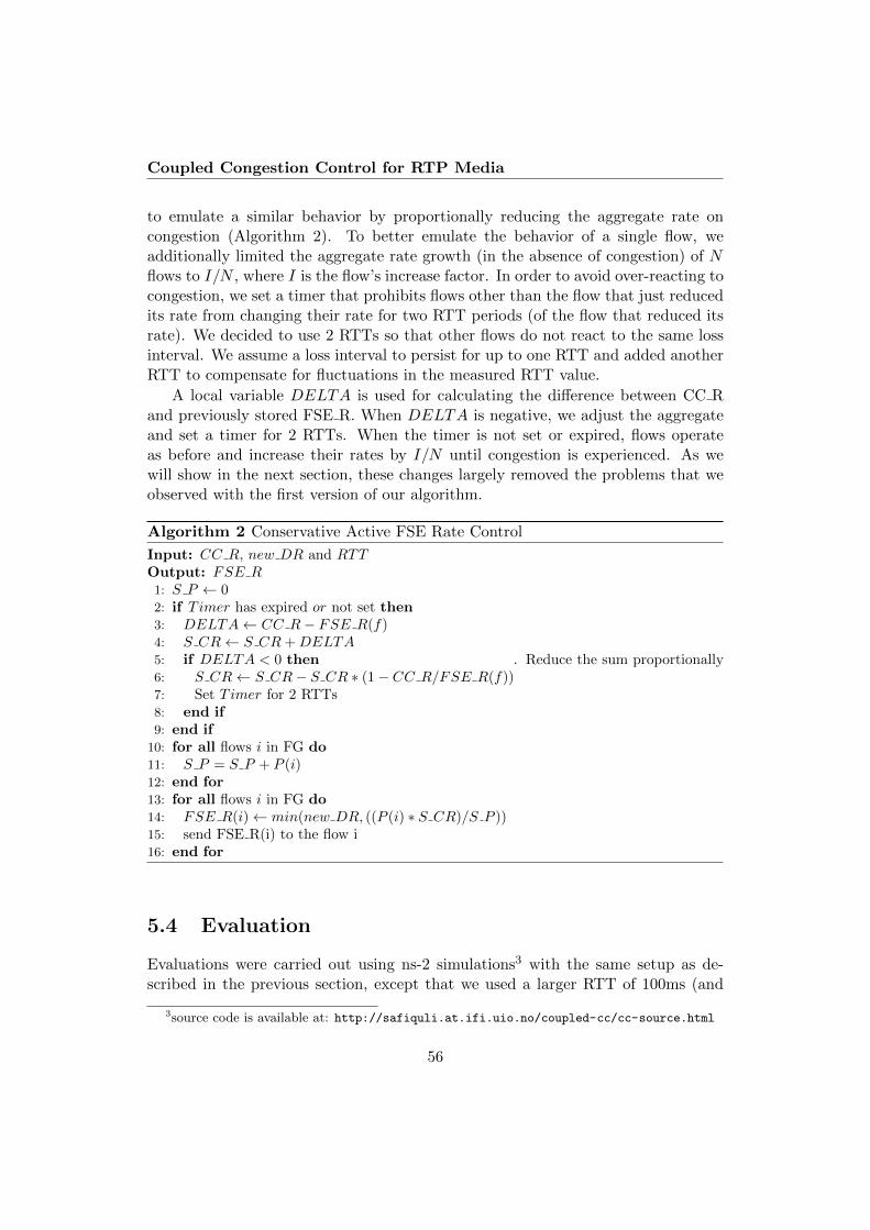
Coupled Congestion Control for RTP Media
to emulate a similar behavior by proportionally reducing the aggregate rate oncongestion (Algorithm 2). To better emulate the behavior of a single flow, weadditionally limited the aggregate rate growth (in the absence of congestion) of Nflows to I/N , where I is the flow’s increase factor. In order to avoid over-reacting tocongestion, we set a timer that prohibits flows other than the flow that just reducedits rate from changing their rate for two RTT periods (of the flow that reduced itsrate). We decided to use 2 RTTs so that other flows do not react to the same lossinterval. We assume a loss interval to persist for up to one RTT and added anotherRTT to compensate for fluctuations in the measured RTT value.
A local variable DELTA is used for calculating the difference between CC Rand previously stored FSE R. When DELTA is negative, we adjust the aggregateand set a timer for 2 RTTs. When the timer is not set or expired, flows operateas before and increase their rates by I/N until congestion is experienced. As wewill show in the next section, these changes largely removed the problems that weobserved with the first version of our algorithm.
Algorithm 2 Conservative Active FSE Rate Control
Input: CC R, new DR and RTTOutput: FSE R1: S P ← 02: if Timer has expired or not set then3: DELTA← CC R− FSE R(f)4: S CR← S CR+DELTA5: if DELTA < 0 then . Reduce the sum proportionally6: S CR← S CR− S CR ∗ (1− CC R/FSE R(f))7: Set Timer for 2 RTTs8: end if9: end if
10: for all flows i in FG do11: S P = S P + P (i)12: end for13: for all flows i in FG do14: FSE R(i)← min(new DR, ((P (i) ∗ S CR)/S P ))15: send FSE R(i) to the flow i16: end for
5.4 Evaluation
Evaluations were carried out using ns-2 simulations3 with the same setup as de-scribed in the previous section, except that we used a larger RTT of 100ms (and
3source code is available at: http://safiquli.at.ifi.uio.no/coupled-cc/cc-source.html
56
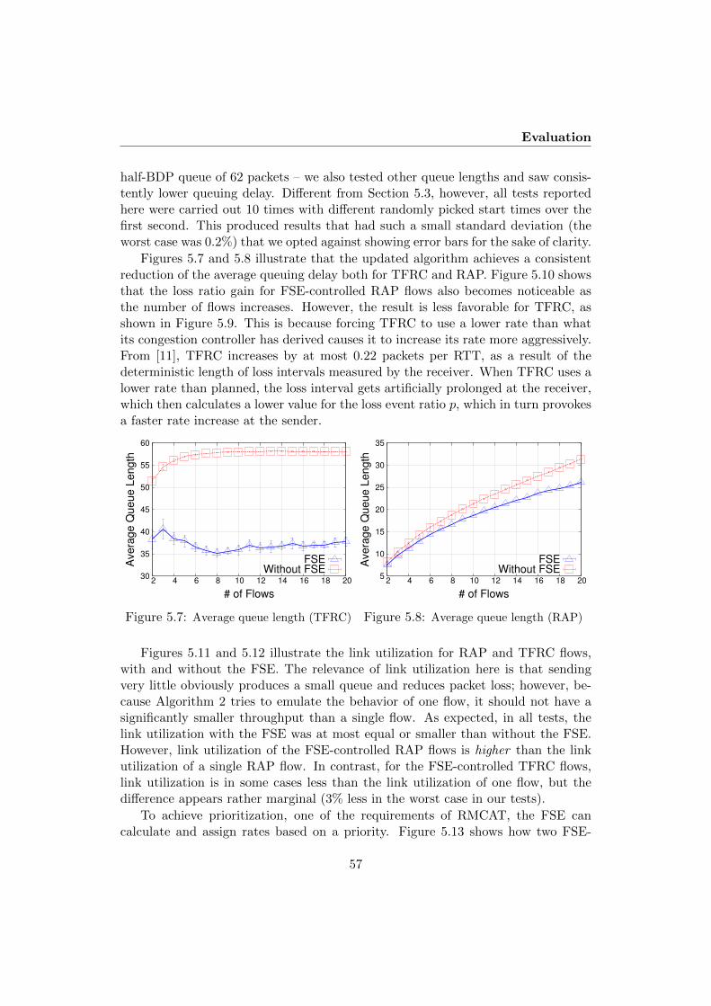
Evaluation
half-BDP queue of 62 packets – we also tested other queue lengths and saw consis-tently lower queuing delay. Different from Section 5.3, however, all tests reportedhere were carried out 10 times with different randomly picked start times over thefirst second. This produced results that had such a small standard deviation (theworst case was 0.2%) that we opted against showing error bars for the sake of clarity.
Figures 5.7 and 5.8 illustrate that the updated algorithm achieves a consistentreduction of the average queuing delay both for TFRC and RAP. Figure 5.10 showsthat the loss ratio gain for FSE-controlled RAP flows also becomes noticeable asthe number of flows increases. However, the result is less favorable for TFRC, asshown in Figure 5.9. This is because forcing TFRC to use a lower rate than whatits congestion controller has derived causes it to increase its rate more aggressively.From [11], TFRC increases by at most 0.22 packets per RTT, as a result of thedeterministic length of loss intervals measured by the receiver. When TFRC uses alower rate than planned, the loss interval gets artificially prolonged at the receiver,which then calculates a lower value for the loss event ratio p, which in turn provokesa faster rate increase at the sender.
30
35
40
45
50
55
60
2 4 6 8 10 12 14 16 18 20
Ave
rag
e Q
ue
ue
Le
ng
th
# of Flows
FSEWithout FSE
Figure 5.7: Average queue length (TFRC)
5
10
15
20
25
30
35
2 4 6 8 10 12 14 16 18 20
Ave
rag
e Q
ue
ue
Le
ng
th
# of Flows
FSEWithout FSE
Figure 5.8: Average queue length (RAP)
Figures 5.11 and 5.12 illustrate the link utilization for RAP and TFRC flows,with and without the FSE. The relevance of link utilization here is that sendingvery little obviously produces a small queue and reduces packet loss; however, be-cause Algorithm 2 tries to emulate the behavior of one flow, it should not have asignificantly smaller throughput than a single flow. As expected, in all tests, thelink utilization with the FSE was at most equal or smaller than without the FSE.However, link utilization of the FSE-controlled RAP flows is higher than the linkutilization of a single RAP flow. In contrast, for the FSE-controlled TFRC flows,link utilization is in some cases less than the link utilization of one flow, but thedifference appears rather marginal (3% less in the worst case in our tests).
To achieve prioritization, one of the requirements of RMCAT, the FSE cancalculate and assign rates based on a priority. Figure 5.13 shows how two FSE-
57

Coupled Congestion Control for RTP Media
0
0.5
1
1.5
2
2.5
2 4 6 8 10 12 14 16 18 20
Pa
cke
t L
oss R
atio
%
# of Flows
FSEWithout FSE
Figure 5.9: Loss ratio (TFRC)
0
1
2
3
4
5
6
7
8
9
10
11
2 4 6 8 10 12 14 16 18 20
Pa
cke
t L
oss R
atio
%
# of Flows
FSEWithout FSE
Figure 5.10: Loss ratio (RAP)
50
60
70
80
90
100
2 4 6 8 10 12 14 16 18 20
Lin
k U
tiliza
tio
n %
# of Flows
FSEWithout FSE
Figure 5.11: Link Utilization (TFRC)
50
60
70
80
90
100
2 4 6 8 10 12 14 16 18 20
Lin
k U
tiliz
atio
n %
# of Flows
FSEWithout FSE
Throughput - 1 flow
Figure 5.12: Link Utilization (RAP)
controlled flows change their rates based on the assigned priorities over time. Thetwo flows started out with a priority of 1 each. After 100 seconds, the priority offlow 1 was decreased to 0.66, 0.42, 0.25 and 0.11 after 100, 150, 200 and 250 seconds,respectively. This means that a high priority flow can easily get the desired ratefrom the FSE without requiring any further changes in its congestion controller. Thefirst 100 seconds of this graph also illustrate the perfect fairness that is enforced byour algorithm; we do not show Jain’s fairness index because the result was always1 in our tests.
To illustrate the effect of changing the queue length, we also investigated theaverage queue length for 5, 10 and 15 RAP and TFRC flows, with and withoutFSE. It is clear from Figures 5.14, 5.15, 5.16 and 5.17 that average queue lengthis consistently lower for the FSE-controlled flows.
The loss ratio is lower for the FSE-controlled RAP flows when the queue lengthis half a BDP as it drains more often. However, the loss ratio is equal or slightlyhigher when the queue is larger. The results are less favorable with TFRC flows.The somewhat surprising increased loss despite a lower average queue is currently
58
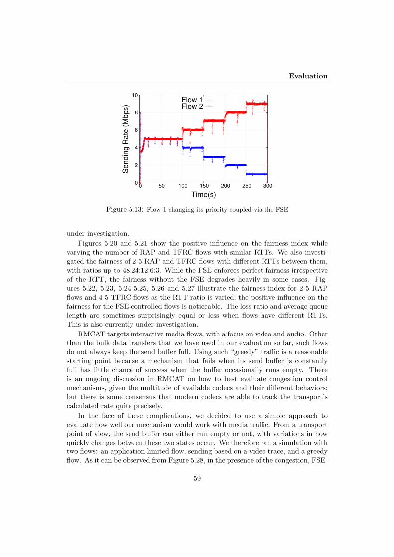
Evaluation
0
2
4
6
8
10
0 50 100 150 200 250 300
Sendin
g R
ate
(M
bps)
Time(s)
Flow 1Flow 2
Figure 5.13: Flow 1 changing its priority coupled via the FSE
under investigation.
Figures 5.20 and 5.21 show the positive influence on the fairness index whilevarying the number of RAP and TFRC flows with similar RTTs. We also investi-gated the fairness of 2-5 RAP and TFRC flows with different RTTs between them,with ratios up to 48:24:12:6:3. While the FSE enforces perfect fairness irrespectiveof the RTT, the fairness without the FSE degrades heavily in some cases. Fig-ures 5.22, 5.23, 5.24 5.25, 5.26 and 5.27 illustrate the fairness index for 2-5 RAPflows and 4-5 TFRC flows as the RTT ratio is varied; the positive influence on thefairness for the FSE-controlled flows is noticeable. The loss ratio and average queuelength are sometimes surprisingly equal or less when flows have different RTTs.This is also currently under investigation.
RMCAT targets interactive media flows, with a focus on video and audio. Otherthan the bulk data transfers that we have used in our evaluation so far, such flowsdo not always keep the send buffer full. Using such “greedy” traffic is a reasonablestarting point because a mechanism that fails when its send buffer is constantlyfull has little chance of success when the buffer occasionally runs empty. Thereis an ongoing discussion in RMCAT on how to best evaluate congestion controlmechanisms, given the multitude of available codecs and their different behaviors;but there is some consensus that modern codecs are able to track the transport’scalculated rate quite precisely.
In the face of these complications, we decided to use a simple approach toevaluate how well our mechanism would work with media traffic. From a transportpoint of view, the send buffer can either run empty or not, with variations in howquickly changes between these two states occur. We therefore ran a simulation withtwo flows: an application limited flow, sending based on a video trace, and a greedyflow. As it can be observed from Figure 5.28, in the presence of the congestion, FSE-
59

Coupled Congestion Control for RTP Media
15
20
25
30
35
40
45
50
55
60
65
70
60 80 100 120 140 160 180
Ave
rag
e Q
ue
ue
Le
ng
th
Queue Length
FSEWithout FSE
Figure 5.14: Average queue length for 10RAP flows while changing the queue lengthfrom 0.5 BDP(62 Packets) to 1.5 BDP (167
packets)
20
30
40
50
60
70
80
90
60 80 100 120 140 160 180
Ave
rag
e Q
ue
ue
Le
ng
th
Queue Length
FSEWithout FSE
Figure 5.15: Average queue length for 15RAP flows while changing the queue lengthfrom 0.5 BDP(62 Packets) to 1.5 BDP (167
packets)
20
40
60
80
100
120
140
160
180
60 80 100 120 140 160 180
Ave
rag
e Q
ue
ue
Le
ng
th
Queue Length
FSEWithout FSE
Figure 5.16: Average queue length for 10TFRC flows while changing the queue
length from 0.5 BDP(62 Packets) to 1.5BDP (167 packets)
20
40
60
80
100
120
140
160
180
60 80 100 120 140 160 180
Ave
rag
e Q
ue
ue
Le
ng
th
Queue Length
FSEWithout FSE
Figure 5.17: Average queue length for 15TFRC flows while changing the queue
length from 0.5 BDP(62 Packets) to 1.5BDP (167 packets)
controlled flows proportionally reduce their rates together, whereas synchronizationcauses the application-limited flows to over-react without the FSE (e.g., in thecongestion events at t=5, 10 and 20 seconds in Figure 5.29).
Figure 5.30 illustrates the behavior of a greedy flow with low priority (0.2) and anapplication limited flow with a higher priority (1) that is sending based on a videotrace. It can be observed that the low-priority flow can grab unused bandwidthas long as there is enough capacity. The bandwidth was not completely utilized inthese tests because the simulation time was based on the total duration of the videotrace, which was too short for the low priority flow to reach the capacity limit.
We conducted a series of simulations using synthetic background traffic in orderto emulate a situation that is typical for the Internet. For this purpose we used
60

Evaluation
4.6
4.8
5
5.2
5.4
5.6
5.8
6
60 80 100 120 140 160 180
Packet Loss R
atio %
Queue-Limit
FSEWithout FSE
Figure 5.18: Loss ratio precentage as thequeue length for 10 RAP flows is varied,
with and without FSE
7.2
7.4
7.6
7.8
8
8.2
8.4
8.6
8.8
60 80 100 120 140 160 180
Packet Loss R
atio %
Queue-Limit
FSEWithout FSE
Figure 5.19: Loss ratio precentage as thequeue length for 15 RAP flows is varied,with and without FSE, with and without
FSE
0.999
0.9992
0.9994
0.9996
0.9998
1
1.0002
1.0004
1.0006
1.0008
1.001
2 4 6 8 10 12 14 16 18 20
Fa
irn
ess I
nd
ex
# of Flows
FSEWithout FSE
Figure 5.20: Fairness index as the numberof TFRC flows is varied, with and without
FSE
0.999
0.9992
0.9994
0.9996
0.9998
1
1.0002
1.0004
1.0006
1.0008
1.001
2 4 6 8 10 12 14 16 18 20
Fa
irn
ess I
nd
ex
# of Flows
FSEWithout FSE
Figure 5.21: Fairness index as the numberof RAP flows is varied, with and without
FSE
TMIX [13], which is a tool to generate realistic TCP application workload in ns-2.The traffic used in our simulation is taken from 60-minute trace of campus trafficat the University of North Carolina, which is available from the common TCPevaluation suite [14].
We employed a pre-processed version of this traffic which is adapted to providean approximate load of 50% on a 10 Mbps bottleneck link based on the networktopology discussed in previous sections over the course of 300 sec as simulation time.The pre-processing also included the removal of non-stationarity in the backgroundtraffic pattern by randomly shuffling different portions of the traffic pattern. TheRTT of background TCP flows generated by TMIX fluctuates between the range of80∼100 ms while the RTT of foreground TFRC flows was statically set to 100 ms,
61

Coupled Congestion Control for RTP Media
0
0.2
0.4
0.6
0.8
1
5:1 10:1 15:1 20:1
Fairness Index
RTT Ratio
FSEWithout FSE
Figure 5.22: Fairness index for 2 RAPflows as the RTT ratio is varied, with and
without FSE
0
0.2
0.4
0.6
0.8
1
1:1:1 8:4:2 16:8:4
Fairness Index
RTT Ratio
FSEWithout FSE
Figure 5.23: Fairness index for 3 RAPflows as the RTT ratio is varied, with and
without FSE
0
0.2
0.4
0.6
0.8
1
1:1:1:1 24:12:6:3 48:24:12:6
Fairness Index
RTT Ratio
FSEWithout FSE
Figure 5.24: Fairness index for 4 RAPflows as the RTT ratio is varied, with and
without FSE
0
0.2
0.4
0.6
0.8
1
1:1:1:1:1 16:8:4:2:1 32:16:8:4:2 48:24:12:6:3
Fairness Index
RTT Ratio
FSEWithout FSE
Figure 5.25: Fairness index for 5 RAPflows as the RTT ratio is varied, with and
without FSE
0
0.2
0.4
0.6
0.8
1
1:1:1:1 24:12:6:3 48:24:12:6
Fairness Index
RTT Ratio
FSEWithout FSE
Figure 5.26: Fairness index for 4 TFRCflows as the RTT ratio is varied, with and
without FSE
0
0.2
0.4
0.6
0.8
1
1:1:1:1:1 16:8:4:2:1 32:16:8:4:2 48:24:12:6:3
Fairness Index
RTT Ratio
FSEWithout FSE
Figure 5.27: Fairness index for 5 TFRCflows as the RTT ratio is varied, with and
without FSE
62

Evaluation
0
2
4
6
8
10
12
14
16
0 5 10 15 20 25
Sendin
g R
ate
(M
bps)
Time (s)
Flow 1Flow 2
Figure 5.28: Application limited flow andgreedy flow – with FSE
0
2
4
6
8
10
12
14
16
0 5 10 15 20 25
Sendin
g R
ate
(M
bps)
Time (s)
Flow 1Flow 2
Figure 5.29: Application limited flow andgreedy flow – without FSE
0
5
10
15
20
25
5 10 15 20 25 30 35 40
Th
rou
gh
pu
t
Capacity
Flow #1Flow #2
Link Utilization
Figure 5.30: High-priority (1) application-limited flow #1 is hardly affected by alow-priority (0.2) greedy flow #2 as long as there is enough capacity for flow #1.
and foreground and background traffic shared the bottleneck queue.
Figure 5.31 shows the goodput values of two TFRC flows with FSE in thepresence of background synthetic traffic when the priority of the first flow is setto 1, while the other flows’ priority is varied. As it can be seen from the graph,the goodputs of flows 1 and 2 are very close to the theoretical value that onemight expect: for example, when the priority of flow 2 is 0.2, 0.5 and 0.8, thegoodput ratio is 0.199 (instead of 0.2), 0.499 (instead of 0.5) and 0.799 (insteadof 0.8), respectively. These are surprisingly precise values, seen by the receivers inthe presence of synthetic background traffic with various numbers of arriving anddeparting flows and RTTs at any instance of time.
63

Coupled Congestion Control for RTP Media
0
1
2
3
4
5
6
0.1 0.2 0.3 0.4 0.5 0.6 0.7 0.8 0.9 1
Goodput (M
bps)
Priority of Flow #2
Flow #1Flow #2
Figure 5.31: Goodput of two FSE-controlled flows competing with synthetic traffic
5.5 Conclusions
We have presented the coupled congestion control mechanism that is currently beingproposed for WebRTC in the IETF RMCAT group. Simulations with the twocongestion control mechanisms RAP and TFRC indicate that, our method notonly satisfies the requirements of controllable fairness with prioritization, but, byemulating the behavior of a single flow, also reduces queuing delay and packetloss without significantly affecting throughput. In case of RAP, we even saw theseeffects combined with better link utilization than with a single flow. The differencein behavior between the two mechanisms highlights the need to evaluate our schemewith each mechanism it is applied to.
We plan to test our method in real life as a next step. The congestion controlof RMCAT is currently under development, and will probably be delay based; wetherefore need to test our scheme with a delay-based congestion control too. Toincorporate WebRTC’s data channel, we will investigate coupling with window-based protocols too; then we can control TCP like E-TCP and EFCM, which willenable us to compare the mechanisms against each other. At this point, it will alsobe necessary to investigate the effect of coupling different congestion controllerstogether. The evaluations in this paper were also limited to a scenario where SBDis based on multiplexing, not measurements. With measurement-based SBD, flowsbetween different host pairs can be controlled, which means that the flows willalso have different RTTs – another factor that needs to be incorporated in futureevaluations.
64

Acknowledgments
5.6 Acknowledgments
This work is partially supported by the European Union through the FP7-ICTproject RITE under contract number 317700. We would like to thank Dr. DavidHayes for his guidance in conducting TMIX tests.
References
[1] H. Balakrishnan, H. S. Rahul, and S. Seshan, “An integrated congestionmanagement architecture for internet hosts,” in Proceedings of the Conferenceon Applications, Technologies, Architectures, and Protocols for ComputerCommunication, ser. SIGCOMM ’99. New York, NY, USA: ACM, 1999, pp.175–187. [Online]. Available: http://doi.acm.org/10.1145/316188.316220
[2] J. Touch, “TCP Control Block Interdependence,” RFC 2140 (Informational),Internet Engineering Task Force, Apr. 1997. [Online]. Available: http://www.ietf.org/rfc/rfc2140.txt
[3] L. Eggert, J. Heidemann, and J. Touch, “Effects of ensemble TCP,” USC/In-formation Sciences Institute, vol. 7, no. 1, December 1999.
[4] M. Savoric, H. Karl, M. Schlager, T. Poschwatta, and A. Wolisz, “Analysis andperformance evaluation of the EFCM common congestion controller for TCPconnections,” Computer Networks, vol. 49, no. 2, pp. 269–294, 2005.
[5] P. Natarajan, P. D. Amer, and R. Stewart, “Multistreamed web transport fordeveloping regions,” in SIGCOMM NSDR workshop, 2008. [Online]. Available:http://doi.acm.org/10.1145/1397705.1397717
[6] M. Welzl, F. Niederbacher, and S. Gjessing, “Beneficial transparent deploymentof SCTP: the missing pieces,” in IEEE GLOBECOM 2011 - Next GenerationNetworking Symposium (GC’11 - NGN), Houston, Texas, USA, Dec. 2011.
[7] “SPDY: An experimental protocol for a faster web,” http://www.chromium.org/spdy/spdy-whitepaper.
[8] M. Welzl, S. Islam, and S. Gjessing, “Coupled congestion control for RTP me-dia,” Internet-draft draft-welzl-rmcat-coupled-cc-02 (work in progress), 2013.
[9] M. Nagy, V. Singh, J. Ott, and L. Eggert, “Congestion control using fec forconversational multimedia communication,” arXiv preprint arXiv:1310.1582,2013.
65

Coupled Congestion Control for RTP Media
[10] R. Rejaie, M. Handley, and D. Estrin, “RAP: An end-to-end rate-based con-gestion control mechanism for realtime streams in the internet,” in IEEE IN-FOCOM, 1999.
[11] S. Floyd, M. Handley, J. Padhye, and J. Widmer, “Equation-based congestioncontrol for unicast applications,” in ACM SIGCOMM, 2000. [Online].Available: http://doi.acm.org/10.1145/347059.347397
[12] C. Holmberg, S. Hakansson, and G. Eriksson, “Web real-time communica-tion use-cases and requirements,” Internet-draft draft-ietf-rtcweb-use-cases-and-requirements-12.txt (work in progress), 2013.
[13] M. C. Weigle, P. Adurthi, F. Hernandez-Campos, K. Jeffay, and F. D. Smith,“Tmix: A tool for generating realistic TCP application workloads in ns-2,”SIGCOMM Comput. Commun. Rev., vol. 36, no. 3, pp. 65–76, July 2006.[Online]. Available: http://doi.acm.org/10.1145/1140086.1140094
[14] L. Andrew, S. Floyd, and G. Wang, “Common TCP Evaluation Suite,” IETF,Internet-Draft draft-irtf-tmrg-tests-02, July 2009, work in Progress. [Online].Available: https://tools.ietf.org/html/draft-irtf-tmrg-tests-02
66

Chapter 6
Managing Real-Time MediaFlows through a Flow StateExchange
Authors. Safiqul Islam, Michael Welzl, David Hayes, and Stein Gjessing
Affiliation. Department of Informatics, University of Oslo, Norway{safiquli, michawe, davihay, steing}@ifi.uio.no
Publication. IEEE/IFIP Network Operations and Management Symposium(NOMS), Istanbul, Turkey, April, 2016
Abstract. When multiple congestion controlled flows traverse the same networkpath, their resulting rate is usually an outcome of their competition at the bot-tleneck. The WebRTC / RTCWeb suite of standards for inter-browser communi-cation is required to allow prioritization. This is addressed by our previously pre-sented mechanism for coupled congestion control, called the Flow State Exchange(FSE). Here, we present our first simulation results using two mechanisms thathave been proposed for IETF standardization: Google Congestion Control (GCC)and Network-Assisted Dynamic Adaptation (NADA). These two mechanisms ex-hibit aspects that allow us to use a simpler “passive” algorithm in our FSE. Passivecoupling allows a less time-constrained request-response style of signaling betweencongestion control mechanisms and the FSE, which enables the FSE to run as astand-alone management tool.
67

Managing Real-Time Media Flows through a Flow State Exchange
6.1 Introduction
Despite the fact that video conference applications have been widely used for manyyears, except for TCP Friendly Rate Control (TFRC) [1], there is no standardizedcongestion control mechanism available. Therefore, the “RTP Media CongestionAvoidance Techniques” (RMCAT)1 IETF Working Group has been established todevelop standards for RTP-based interactive real-time media, with a focus on help-ing WebRTC (and the related IETF set of standards, RTCWeb). WebRTC enablesinteractive real-time communication between web browsers, facilitating a range ofapplications such as seamless video conferencing, telephony and interactive gaming.These should all be accessible as part of the web surfing experience and not requirethe installation of additional software. One important RTCWeb requirement forRMCAT standards is the ability to allow the WebRTC application programmerto assign priorities to flows. These priorities control how the available capacity isshared [2].
In a recent work [3] we proposed the Flow State Exchange (FSE); a mecha-nism that couples congestion control for RMCAT. The FSE couples the congestioncontrols of competing RMCAT flows with priorities—even between combinations ofdifferent congestion control mechanisms. It enables the sender to precisely controlprioritized bandwidth sharing, removing self-competition. This improves the overallperformance, reducing delay and loss [3].
Having shown in [3] how the FSE performs with the Rate Adaption Protocol(RAP) [4] and TFRC [1], we now investigate its usage for two proposed RMCATcongestion control mechanisms: Network-Assisted Dynamic Adaptation (NADA)[5] and Google Congestion Control (GCC) [6]. Among these congestion controlmechanisms, GCC has already been deployed in Google Chrome, Chromium, Fire-fox, and Opera browsers.
Applying the FSE to different congestion control algorithms requires a smalladaption to the FSE algorithm. In this paper, we show how this is done for NADAand GCC, leading us to an interesting observation: because both NADA and GCCupdate their rates at fixed time intervals – and not as a function of the RTT –we can use an even simpler, “passive” version of our algorithm. Different from ourprevious “active” version [3], which required immediate callbacks, the passive FSEalgorithm can be implemented as a simple request-response type server, with lesssignaling overhead and relaxed time constraints. This makes it possible to run theFSE as a stand-alone application, potentially turning it from an integral part of anapplication’s congestion control into a separate tool for managing priorities betweenflows.
We believe that a standalone FSE tool will have uses beyond the scope of justWebRTC, where support of priorities is a requirement [2]. This belief is supported
1http://tools.ietf.org/wg/rmcat/
68

Background and related work
by the results of a survey in which we asked 139 students and work colleagueswhether they had experienced network traffic from different applications interferingwith each other on their computers. 96 of them responded “yes, and I found itannoying”, 19 chose “yes but I did not care” and the remaining 24 chose “No: thisnever happened – or if it did, I did not notice”. Asked if they would use a tool thatwould be easy to handle and would let them prioritize how applications access thenetwork, 89 participants said yes, 11 said no, and 39 used a free-text field to givea different answer, such as (relatively common) “I already use QoS mechanisms”.While the QoS argument is valid, it requires knowledge of and access to the mostcommon bottleneck link (often the access point), that not all users have.
This paper is organized as follows: Section 6.2 presents background information(NADA and GCC) and related work. Section 6.3 explains our FSE algorithm andhow we have changed it for NADA and GCC. In Section 6.4 we show some evalua-tion results using ns-2 simulations for NADA and simulations using the Chromiumbrowser for GCC, with conclusions in Section 6.5.
6.2 Background and related work
Network-Assisted Dynamic Adaptation (NADA) [5, 7] is a congestion control schemedesigned for interactive real-time media applications. In NADA, the receiver com-bines both implicit (per-packet drops and one way delay measurements) and ex-plicit signals into a composite congestion signal, and periodically reports back tothe sender using the Real-Time Transport Control Protocol (RTCP). The senderthus regulates its sending rate upon receipt of the RTCP feedback. It can be seenfrom the simulation results in [7] and [8] that the algorithm achieves good fairnessby maintaining a stable queue when multiple NADA and TCP flows compete.
Google Congestion Control (GCC) [6] is another congestion control algorithmproposed for WebRTC. GCC employs two controllers: (i) a sender side controller,and (ii) a receiver side controller. The sender side controller controls the bandwidthbased on packet loss, and the receiver side controller controls the bandwidth basedon delay. These two controllers are designed to increase the rate in the absenceof congestion. Interestingly, the sender side controller only reacts to losses over 10percent. In [9, 10], the authors showed that in a previous version, GCC starvedwhen competing with TCP. However, recent changes [11] show that the algorithmnow can achieve good fairness while minimizing queuing delay.
There have been a number of earlier end system flow management efforts. Thefirst work to combine flow management used a mechanism that enabled TCP’sControl Block (TCB) to be shared among flows [12]. This shared state is used toinitialize new connections. Ensemble TCP (E-TCP) builds upon [12], extending itto let multiple parallel flows immediately benefit from each other [13]. The authorsof [14] extend E-TCP’s concepts with their Ensemble Flow Congestion Manager
69

Managing Real-Time Media Flows through a Flow State Exchange
(EFCM). In E-TCP, the ensemble of n TCP connections is no more aggressive thanone TCP connection, however, EFCM allows the ensemble to be as aggressive as nseparately controlled TCP connections. In [15], an integrated Congestion Manager(CM) was proposed that replaces each flow’s congestion control mechanism withits own common rate based mechanism. CM was eventually standardized [16],however, it is hard to implement and has never been widely deployed. Our FSEdoes not provide a new congestion control mechanism, rather it provides a simpleprotocol interface that facilitates the coupling of flows using their own congestioncontrollers. This enables it to support an extensible list of transport protocolswithout the implementation complexity or single protocol dependency that hashampered adoption of the other mechanisms.
6.3 The Flow State Exchange (FSE)
Because prior approaches such as the Congestion Manager did not see wide-spreaddeployment and have been reputed to be too complex to implement, we haveopted for an approach that minimizes changes to existing congestion control mech-anisms [17], called the “Flow State Exchange” (FSE).
The FSE couples flows that compete for shared capacity. Since routers or othermiddle-boxes usually identify flows using a five-tuple of source and destination IPaddresses, transport protocol, and the transport protocol’s source and destinationport numbers, we use this to identify flows that should be coupled together. Inaddition, flows that have a different five-tuple, but share a common bottleneck, canalso be coupled together. This can be achieved through the use of a measurementbased Shared Bottleneck Detection mechanism [18, 19]—however in this paper wesimplify the discussion by assuming that all coupled flows have the same five-tuple.This is the case for flows between the same two browsers in WebRTC or for a moreheterogeneous set of flows in certain tunnels (e.g. when using a VPN). The FSEcan be either in the same sender host or in the same local network. Fig. 6.1 showsthe interaction of two media sources S1 and S2 connected to D1 and D2 with theFSE on the sources’ local network.
Applying the FSE to a congestion control algorithm requires a fundamentalunderstanding of the algorithm and then performing some straightforward adap-tions. Two major elements govern the dynamic behavior resulting from an FSE:the update frequency and the decision on how rates are increased or decreased.
6.3.1 Active vs. passive updates
The FSE can be implemented in two basic ways: active and passive. In the activeversion, it initiates communication with flows. In the passive version, it does notinitiate communication with flows, but instead maintains the state of coupled flows,
70

The Flow State Exchange (FSE)
Internet
S1
S2
D1
D2
FSE
Figure 6.1: System architecture, showing the relationship between the FSE andtwo sources, S1 and S2
making it available to flows requesting flow state information. Fig. 6.2 illustratesthe interaction between flows and the FSE in the active and passive variants.
The passive version (see Fig. 6.2(b)) is easier to implement than the activeversion. It requires less signalling, with inherently relaxed timing constraints, anddoes not require tight integration with the congestion control mechanism. Thismeans that a passive FSE could be implemented as a stand-alone tool. However,a passive FSE can create problems with flows that do not update their rate forrelatively longer periods – typically because RTTs are significantly different. Thisis shown in Fig. 6.3, where two TCP flows are coupled using a passive FSE inns-2 simulations (dumbbell topology, 3 Mbps bottleneck, and a queue length of 13packets). Because TCP updates its rate as a function of the RTT, large RTTdifferences also delay the feedback from the FSE. This prevents the FSE fromimposing strict fairness (in the test shown in Fig. 6.3, both flows have the samepriority).
Consider two flows, flow 1 with a slow update frequency (i.e., a long RTT) andflow 2 with fast update frequency (short RTT). If flow 1 sends at a high rate andflow 2 wants to decrease the rate because it sees congestion, a passive FSE algorithmwill make an overall decision for the rate aggregate and assign an appropriate rateto each flow (this is a necessary part of any FSE algorithm that assigns priorities).This means that it will probably record that flow 1 should reduce its rate. However,flow 1 does not incorporate this update for a long time and keeps on sending toofast. Thus, if the rate update of flow 2 is based on an assumption about flow 1, thisassumption is wrong and the overall outcome is undesirable leading to the behaviorwe observe in Fig. 6.3).
This can be solved by choosing the active variant (see Fig. 6.2(a)), where allflows immediately incorporate updates from each other (as in [3]). As our discussionof NADA and GCC will show that the active version is superfluous to their needs.
71

Managing Real-Time Media Flows through a Flow State Exchange
Flow 1 FSE Flow 2
Register
Register
New rateCC R(1)
Update rate
Rate updated by FSE Rate updated by FSEFSE R(1) FSE R(2)
New rateCC R(2)
Update rate
Rate updated by FSE Rate updated by FSEFSE R(1) FSE R(2)
msc Active FSE
(a) Active FSE from [3]. The FSE initiates updates whenever the FSE state changes.
Flow 1 FSE Flow 2
Register
Register
New rateCC R(1)
Update rate
Rate updated by FSEFSE R(1)
New rateCC R(2)
Update rate
FSE R(2)Rate updated by FSE
msc Passive FSE
(b) Passive FSE: flows asynchronously synchronize their state with the FSE whenever theychange their sending rate or congestion window.
Figure 6.2: Active and Passive versions of the FSE. CC R is the rate receivedfrom the flow’s congestion controller. FSE R(f) is the rate calculated by the FSE.
Variables are explained in Section 6.3.5 and Table 6.1.
72

The Flow State Exchange (FSE)
1:1 1:2 1:3 1:4 1:5
RTT ratio
0.820.840.860.880.900.920.940.960.981.00
Fairn
ess
inde
x
Figure 6.3: Jain’s fairness index [20] for two TCP flows with heterogeneous RTTscoupled with the passive FSE. TCP’s fairness deteriorates as the flow RTT ratio
decreases due to the lag in adopting the FSE assigned rate.
6.3.2 Increasing and decreasing rates
If the FSE algorithm leaves the increase behavior unchanged, the overall increasebehavior is more aggressive when compared to a single flow. This is the behavioradopted in [3, 17]. An FSE algorithm can also force the increase behavior to beexactly like one flow. For example, if the increase behavior is additive as in AIMD,this can be done by only allowing one flow to increase the rate of the aggregate perupdate interval. This would be a more conservative behavior.
If the FSE algorithm leaves the decrease behavior unchanged, the overall be-havior is more aggressive than only a single flow. Consider, for example, 10 AIMD(Additive-Increase, Multiplicative-Decrease) flows sending with a rate of x bits persecond each without using an FSE. The aggregate rate of these flows is 10x. If onlyone of them experiences congestion and that causes that flow to halve its rate (MDwith multiplication factor 0.5), the rate aggregate will only be reduced to 9.5x. Inreality, flows often get synchronized, increasing the chance for multiple flows to seecongestion during the same round-trip time. If all flows saw congestion at the sametime in our example, the aggregate would end up at a rate of 5x. Thus, dependingon how synchronized the flows are, the outcome is somewhere between halving theentire aggregate or only halving the rate of a single flow.
The “active conservative” algorithm in [3, 17] forces the decrease behavior tobe like one flow. This decision was taken to allow the queue to drain more oftenbecause the goal was to achieve lower loss and delay. A single congestion controllike TCP also tries to avoid reacting more than once per loss event (RTT), so thisbehaviour also had to be incorporated into the design.
73

Managing Real-Time Media Flows through a Flow State Exchange
Figure 6.4: One-way delay of one NADA flow and one GCC flow across a 1 Mbps,50 ms base delay link (separate simulations).
6.3.3 Application to NADA
NADA has the following relevant properties:
Building a stable queue
NADA primarily reacts to delay signals and updates rates gradually when a receiverreports a standing, increasing or decreasing queue; Fig. 6.4 illustrates the delaycharacteristics of one NADA flow compared with that of a GCC flow.
Accelerated ramp up
A NADA sender uses two different modes to update its sending rate: gradual rateupdate and accelerated ramp up. In accelerated ramp up mode, a NADA flowincreases its rate faster when the reported queuing delay is close to zero [5].
Rate update frequency
A NADA receiver sends an update to the sender every 100 ms, and the senderupdates its sending rate whenever feedback arrives.
Derived implications for the FSE algorithm:
74

The Flow State Exchange (FSE)
Increase There is no obvious reason to change the increase behavior of NADA,so the FSE can leave it unaltered, similar to the version in [3].
Decrease Here, the active conservative algorithm proposed in [3] drains the queuemore often than multiple NADA flows normally would do because it proportionallyreduces the rates of all flows. While this by itself is not bad, it triggers the acceler-ated ramp up more often, in turn rendering the flows more aggressive again. Hencewe found that leaving the decrease behavior unchanged is a better choice.
Active or passive Because the rate update frequency is fixed, any error intro-duced by passive updates persists for at most the length of the update interval.Hence, it is limited by a fixed value (as opposed to the RTT, e.g. in TCP), andhence the predictable regular updates make the “active” FSE behavior superfluous.
6.3.4 Application to GCC
The following two properties of GCC are relevant for the FSE:
Builds a stable queue
Since GCC reacts to delay signals, it builds a stable queue similar to NADA.Fig. 6.4 illustrates the delay characteristics of one GCC flow.
Rate update frequency From the most recent specification of GCC in [6], thefrequency at which a sender updates its rate (immediately upon receiving feed-back from the receiver or based on a timer) is not fully defined. According to [9],the frequency of sending feedback from the receiver is still an open issue. TheGoogle implementation in the version of Chromium that was used for this paper(47.0.2494.0) updates the sending rate every 25 ms and whenever a feedback mes-sage arrives; these messages were sent every 50 ms second or if there is rate drop ofat least 3%. The latter rarely occurred in our tests, meaning that approximatelyevery other rate update was caused by the 25 ms timer.
Derived implications for the FSE algorithm:
Increase There is no obvious reason to change the increase behavior of GCC, sothe FSE can leave it unaltered, similar to the version in [3].
Decrease In early tests, we did not see any major issues with the decrease be-havior of the active conservative algorithm proposed in [3]. However, given that themechanism is by itself delay based, the benefits of such a conservative decrease rule
75

Managing Real-Time Media Flows through a Flow State Exchange
are limited so we opted for leaving the decrease behavior unchanged for the sake ofsimplicity.
Active or passive Because rate update timers operate independently from theRTT, the frequency at which GCC flows change their rates and hence access theFSE is also RTT-independent. Again, the “active” FSE behavior is probably un-necessary.
6.3.5 A simple passive FSE algorithm for NADA and GCC
The outcome of the active FSE algorithm design in [3] is that flows using the FSEare a bit more aggressive than one flow but less aggressive than multiple: theyincrease the aggregate rate faster but allow the queue to drain more often. As ourdiscussion has shown, many of the design decisions taken in our active variantsare either unnecessary or inappropriate for NADA or GCC, rendering the resultingalgorithm significantly simpler.
The passive FSE algorithm is summarized in Algorithm 3; variables are ex-plained in Table 6.1. The FSE contains a list of all flows that have registered withit. Each flow has the following state:
(i) a unique flow number to identify the flow,(ii) the Flow Group (FG) identifier indicating the group it belongs to (all flows in
the same FG are assumed to share the same bottleneck in the network),(iii) a flow priority P,(iv) and the calculated rate FSE R.
Each FG contains one global variable S CR which is the sum of the calculated ratesof all flows in the same FG. The FSE keeps track of the total rate of all flows andassigns each flow a share that is weighted by the flow’s priority.
Algorithm 3 Passive FSE Rate Control for flow f
Input: CC R(f)Output: FSE R(f)
1: S P← 02: S CR ← S CR + CC R(f) - FSE R(f)3: for all flows i in FG do4: S P ← S P + P(i)5: end for6: FSE R(f) ← ((P(f) × S CR) / S P))7: send FSE R(f) to the flow
76

Evaluation
Variables Description
CC R (f) The rate received from f’s congestion controller when a flowcalls UPDATE
FSE R(f) The rate calculated by the FSE for flow f
S CR The sum of the calculated rates of all flows in the same FG;this value is used to calculate the sending rate
FG A group of flows having the same FGI, and hence sharingthe same bottleneck
P(f) The priority of flow f which is received from the flow’s con-gestion controller; the FSE uses this variable for calculatingFSE R(f)
S P The sum of all the priorities
Table 6.1: Names of variables used in Algorithm 3
S1
S2
Sn
D1
D2
Dn
R1 R2
Figure 6.5: Topology used in our experiments
6.4 Evaluation
We implemented the FSE in ns-22 and the Chromium browser3. The actual behaviorof media flows in the browser is codec-dependent and hard to characterize. TheIETF RMCAT group has prepared a number of test cases [21] to evaluate theperformance of congestion control mechanisms. In accordance with [21], all testsuse the dumbbell topology depicted in Fig. 6.5, with a bottleneck queue lengthchosen to produce a maximum delay of 300 ms. For all figures except Fig. 6.7and 6.8, the one-way path delay is 50 ms. From Fig. 6.7 to Fig. 6.8 the link capacityis 4 Mbps, and from Fig. 6.9 to Fig. 6.10 the link capacity is 3.5 Mbps.
In this paper, we first show the prioritization results for both NADA and GCC
2http://www.isi.edu/nsnam/ns/3https://www.chromium.org
77

Managing Real-Time Media Flows through a Flow State Exchange
flows, then the results using two pertinent test cases4 from [21] in order to documentthe efficacy of our proposed solution, and finally test our system’s efficacy whenfeedback is delayed. The two test cases are:
1. Round-trip time fairness: In this test case, five media sources S1, S2, S3, S4,and S5 are connected to D1, D2, D3, D4, and D5 media sinks, respectively(n=5 in Fig. 6.5). The one way base delays are, 10 ms for S1-D1, 25 ms forS2-D2, 50 ms for S3-D3, 100 ms for S4-D4, and 150 ms for S5-D5, respectively.
2. Media pause and resume: In this test case, three media sources S1, S2, andS3 are connected to D1, D2, and D3, respectively (n=3 in Fig. 6.5). S2 ispaused for 20 seconds at around 40 seconds.
Results of tests from [21] are commonly presented in the form of the sending rateand packet transit delay evolution over time. This illustrates the dynamic behaviorand we follow the same format in this paper.
6.4.1 Prioritization results
The FSE calculates and assigns rates based on priorities. Fig. 6.6 shows how threeFSE-controlled flows change their rates based on the assigned priorities over time.Fig. 6.6(a) and 6.6(b) illustrate the sending rates for three FSE-controlled NADAflows and three FSE-controlled GCC flows, respectively. The three flows startedout with a priority of 1 each. At around 50 s, the priorities of streams 2 and 3 weredecreased to 0.66 and 0.33, respectively. This means that flows get their assignedproportion of the available capacity without requiring any further changes in thecongestion controllers.
6.4.2 Test case results
Fig. 6.7 and 6.8 show results for the test case “round-trip time fairness” for five RM-CAT flows with different round-trip times. The one way propagation delays of flowsare 10 ms, 25 ms, 50 ms, 100 ms, and 150 ms, respectively. Fig. 6.7(b) and 6.8(b)show that the FSE helps both NADA and GCC flows to converge more quickly thanwithout the FSE (Fig. 6.7(a) and 6.8(a)).
Fig. 6.9 and 6.10 show results for both NADA and GCC with two continuousand one intermittent RMCAT flows in the “media pause and resume” test case [21].Fig. 6.9(a) and 6.10(a) show the rate and delay characteristics without the FSE, andFig. 6.9(b) and 6.10(b) show results with the FSE for NADA and GCC respectively.In this test, all three flows start with the same priority. At around 40 s flow 1 waspaused for 20 seconds. Fig. 6.9(b) and 6.10(b) show that the FSE distributes the
4Test results of all the test cases of the active version have been presented, see [22, 23].
78
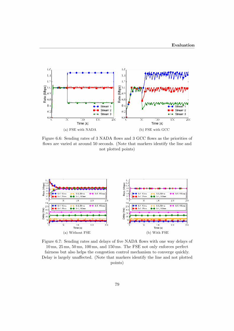
Evaluation
(a) FSE with NADA (b) FSE with GCC
Figure 6.6: Sending rates of 3 NADA flows and 3 GCC flows as the priorities offlows are varied at around 50 seconds. (Note that markers identify the line and
not plotted points)
(a) Without FSE (b) With FSE
Figure 6.7: Sending rates and delays of five NADA flows with one way delays of10 ms, 25 ms, 50 ms, 100 ms, and 150 ms. The FSE not only enforces perfect
fairness but also helps the congestion control mechanism to converge quickly.Delay is largely unaffected. (Note that markers identify the line and not plotted
points)
79

Managing Real-Time Media Flows through a Flow State Exchange
(a) Without FSE (b) With FSE
Figure 6.8: Sending rates and delays of five GCC flows with one way delays of10 ms, 25 ms, 50 ms, 100 ms, and 150 ms. The FSE not only enforces perfect
fairness but also helps the congestion control mechanism to converge quickly.Delay is largely unaffected. (Note that markers identify the line and not plotted
points)
aggregate fairly by enforcing strict fairness. The FSE also improves the delay spikeintroduced by a NADA flow (see Fig. 6.9) or a GCC flow (see Fig. 6.10) after a longpause.
6.4.3 Delayed feedback tests
In order to see if our mechanism would be robust against operating system distur-bance if the FSE would be run as a stand-alone application, we ran tests with 2GCC flows where we delayed the signal between the congestion controller of flow 1and the FSE while keeping the delay between the congestion controller of flow 2 andthe FSE fixed. The link capacity was 3 Mbps. It can be seen from Fig. 6.11 thatthe rate allocation is slightly affected when we increase the fixed delay from 50 msto 100 ms (see Fig. 6.11(a) and 6.11(b) compared to tests without delayed feed-back (see Fig. 6.8(b) and 6.10(b)). Realistically, the delay between the FSE and aflow’s congestion controller may fluctuate. To illustrate this behavior, we vary thedelay between the congestion controller of flow 1 and the FSE. Delay is selectedfrom a uniformly random distribution where values vary between 1 and 100 ms.Fig. 6.11(c) demonstrates the robustness of the FSE as the flows can achieve a fairrate allocation even with delayed feedback. The same tests with two NADA flowsalso yielded very good rate allocation, just as in Fig. 6.7(b).
We also carried out tests with delay values beyond the ones shown in Fig. 6.11(even up to 500 ms), with similar results. Less time-constrained request-response
80

Evaluation
(a) Without FSE (b) With FSE
Figure 6.9: Sending rates and delays of two continuous and one intermittentNADA flows, with and without the FSE. (Note that markers identify the line and
not plotted points)
(a) Without FSE (b) With FSE
Figure 6.10: Sending rates and delays of two continuous and one intermittentGCC flows, with and without the FSE. (Note that markers identify the line and
not plotted points)
81

Managing Real-Time Media Flows through a Flow State Exchange
0 50 100 150 200Time (s)
0.0
0.2
0.4
0.6
0.8
1.0
1.2
1.4
1.6
Rate
(Mbp
s)
Stream 1 Stream 2
(a) 50 ms delay between the FSE and stream 1
0 50 100 150 200Time (s)
0.0
0.2
0.4
0.6
0.8
1.0
1.2
1.4
1.6
Rate
(Mbp
s)
Stream 1 Stream 2
(b) 100 ms delay between the FSE and stream1
0 50 100 150 200Time (s)
0.0
0.2
0.4
0.6
0.8
1.0
1.2
1.4
1.6
Rate
(Mbp
s)
Stream 1 Stream 2
(c) Delay between the FSE and stream 1 wasbased on uniformly distributed random
number between 0 and 100 ms
Figure 6.11: Two GCC flows coupled via the FSE, where delay between stream 1and the FSE is varied based on (a) fixed delay of 50 ms (b) fixed delay of 100 ms,
and (c) uniformly distributed random delay, between 1 and 100 ms.
82

Conclusions
style signaling between congestion control mechanisms and the FSE adds to itsrobustness. This makes it possible to run the FSE as a stand-alone application.
6.5 Conclusions
In this paper, we have evaluated our FSE management mechanism with the twocongestion control algorithms NADA and GCC. The evaluations show that thesimpler, passive version of FSE works very well with both NADA and GCC flows.Both NADA and GCC update their rates at fixed intervals, and we have arguedthat this is the reason the passive version of the FSE manages these flows so well.
A passive FSE uses less signaling than an active one. In addition we have shownthat a passive FSE works well with relaxed timing constraints vis-a-vis the conges-tion controllers, making it possible to run the FSE as a stand-alone tool and evenon a separate system, i.e. as a server that clients query to obtain the right sendingrate. While this could multiply the benefits of the FSE by uniformly controllingseveral hosts, the FSE always needs to be aware of the common bottleneck, whichmay complicate the design of such a system. We plan to investigate this in futurework. In the RMCAT context, we will also evaluate the passive FSE with the thirdcurrently proposed mechanism, SCReAM [24]. We expect similar results becauseSCReAM also employs a fixed feedback frequency. However, the passive FSE mech-anism could be applied to any set of flows that share similar properties, not justreal-time media flows. We therefore also plan to investigate whether the passiveFSE can be used to control such non-real-time media mechanisms in future work.
6.6 Acknowledgments
This work is partially supported by the European Union through the FP7-ICTproject RITE under contract number 317700. The authors would like to thank theanonymous reviewers for their valuable comments and suggestions to improve theoverall quality of the paper. The authors would also like to thank Xiaoqing Zhuand Stefan Holmer for helping out with NADA and GCC respectively, and KristianHiorth for his advice regarding Chromium.
References
[1] S. Floyd, M. Handley, J. Padhye, and J. Widmer, “Equation-based congestioncontrol for unicast applications,” in ACM SIGCOMM, 2000. [Online].Available: http://doi.acm.org/10.1145/347059.347397
[2] R. Jesup and Z. Sarker, “Congestion control requirements for in-teractive real-time media,” draft-ietf-rmcat-cc-requirements-09 (work in
83

Managing Real-Time Media Flows through a Flow State Exchange
progress), Dec. 2014. [Online]. Available: http://www.ietf.org/internet-drafts/draft-ietf-rmcat-cc-requirements
[3] S. Islam, M. Welzl, S. Gjessing, and N. Khademi, “Coupled congestion controlfor RTP media,” in Capacity Sharing Workshop of ACM SIGCOMM 2014,Aug. 2014.
[4] R. Rejaie, M. Handley, and D. Estrin, “RAP: An end-to-end rate-based con-gestion control mechanism for realtime streams in the internet,” in IEEE IN-FOCOM, 1999.
[5] X. Zhu, R. Pan, M. A. Ramalho, S. Mena, C. Ganzhorn, P. E. Jones, and S. D.Aronco, “NADA: A unified congestion control scheme for real-time media,”draft-ietf-rmcat-nada-00 (work in progress), 2015.
[6] S. Holmer, H. Lundin, G. Carlucci, L. D. Cicco, and S. Mascolo, “A googlecongestion control algorithm for real-time communication,” draft-alvestrand-rmcat-congestion-03 (work in progress), 2015.
[7] X. Zhu and R. Pan, “NADA: A unified congestion control scheme for low-latency interactive video,” in Packet Video Workshop (PV), 2013 20th Inter-national. IEEE, 2013, pp. 1–8.
[8] X. Zhu, “Presentation on NADA: A unified congestion control schemefor real-time media,” IETF 91, Honolulu, 2014. [Online]. Avail-able: http://www.ietf.org/proceedings/interim/2014/11/09/rmcat/slides/slides-interim-2014-rmcat-1-2.pdf
[9] L. De Cicco, G. Carlucci, and S. the, “Experimental investigation of the googlecongestion control for real-time flows,” in Proceedings of the 2013 ACM SIG-COMM workshop on Future human-centric multimedia networking. ACM,2013, pp. 21–26.
[10] V. Singh, A. A. Lozano, and J. Ott, “Performance analysis of receive-side real-time congestion control for webrtc,” in Packet Video Workshop (PV), 201320th International. IEEE, 2013, pp. 1–8.
[11] S. Holmer, “GCC: Emulation results,” IETF 93, Prague, 2015. [Online]. Avail-able: https://www.ietf.org/proceedings/interim/2015/07/19/rmcat/slides/slides-interim-2015-rmcat-1-2.pdf
[12] J. Touch, “TCP control block interdependence,” April 1997.
[13] L. Eggert, J. Heidemann, and J. Touch, “Effects of ensemble TCP,” USC/In-formation Sciences Institute, vol. 7, no. 1, December 1999.
84

References
[14] M. Savoric, H. Karl, M. Schlager, T. Poschwatta, and A. Wolisz, “Analysis andperformance evaluation of the EFCM common congestion controller for TCPconnections,” Computer Networks, vol. 49, no. 2, pp. 269–294, 2005.
[15] H. Balakrishnan, H. S. Rahul, and S. Seshan, “An integrated congestionmanagement architecture for internet hosts,” in Proceedings of the Conferenceon Applications, Technologies, Architectures, and Protocols for ComputerCommunication, ser. SIGCOMM ’99. New York, NY, USA: ACM, 1999, pp.175–187. [Online]. Available: http://doi.acm.org/10.1145/316188.316220
[16] H. Balakrishnan and S. Seshan, “The Congestion Manager,” June 2001.
[17] S. Islam, M. Welzl, and S. Gjessing, “Coupled congestion control forRTP media,” draft-ietf-rmcat-coupled-cc-00 (work in progress), Sept. 2015.[Online]. Available: https://tools.ietf.org/html/draft-ietf-rmcat-coupled-cc
[18] D. Hayes, S. Ferlin, and M. Welzl, “Shared bottleneck detection forcoupled congestion control for RTP media,” Internet Draft draft-ietf-rmcat-sbd, work in progress, May 2015. [Online]. Available: http://tools.ietf.org/html/draft-ietf-rmcat-sbd
[19] D. A. Hayes, S. Ferlin, and M. Welzl, “Practical passive shared bottleneckdetection using shape summary statistics,” in 2014 IEEE 39th Conference onLocal Computer Networks (LCN). IEEE, 2014, pp. 150–158.
[20] R. Jain, D. Chiu, and W. Hawe, “A Quantitative Measure of Fairness andDiscrimination for Resource Allocation in Shared Computer Systems,” DECResearch, Technical report TR-301, Sept. 1984.
[21] Z. Sarker, V. Singh, X. Zhu, and M. A. Ramalho, “Test cases for evaluatingRMCAT proposals,” draft-ietf-rmcat-eval-test-01 (work in progress), 2015.
[22] S. Islam, “Presentation on coupled congestion control for RTP media,” IETF93, Prague, 2015. [Online]. Available: http://www.ietf.org/proceedings/93/slides/slides-93-rmcat-3.pptx
[23] S. Islam, “Presentation on coupled congestion control with GCC forRTP media,” IETF 94, Yokohama, 2015. [Online]. Available: http://www.ietf.org/proceedings/94/slides/slides-94-rmcat-5.pdf
[24] I. Johansson and Z. Sarker, “Self-clocked rate adaptation for multimedia,”draft-ietf-rmcat-scream-cc-01 (work in progress), 2015.
85

Managing Real-Time Media Flows through a Flow State Exchange
86

Chapter 7
Start Me Up: Determining andSharing TCP’s InitialCongestion Window
Authors. Safiqul Islam and Michael Welzl
Affiliation. Department of Informatics, University of Oslo, Norway{safiquli, michawe}@ifi.uio.no
Publication. ACM, IRTF, ISOC Applied Networking Research Workshop 2016(ANRW 2016), Berlin, Germany, July 2016.
Abstract. When multiple TCP connections are used between the same host pair,they often share a common bottleneck – especially when they are encapsulatedtogether, e.g. in VPN scenarios. Then, all connections after the first should nothave to guess the right initial value for the congestion window, but rather getthe appropriate value from other connections. This allows short flows to completemuch faster – but it can also lead to large bursts that cause problems on their own.Prior work used timer-based pacing methods to alleviate this problem; we introducea new algorithm that “paces” packets by instead correctly maintaining the ACKclock, and show its positive impact in combination with a previously presentedcongestion coupling algorithm.
7.1 Introduction
Finding a suitable initial congestion window (cwnd) has been debated for manyyears in the IETF. A large Initial Window (IW) can be very beneficial [1], yet prob-
87

Start Me Up: Determining and Sharing TCP’s Initial CongestionWindow
lematic for low bandwidth links, e.g. in developing countries (although RFC 6928 [2]discusses a study involving South America and Africa, this has been criticized forfocusing on the flows that used the proposed larger initial window instead of mea-suring the impact on competing traffic). This is a difficult engineering trade-offbecause TCP normally assumes no prior knowledge about the path when it appliesthe IW.
Often, concurrent TCP connections are used between the same source-destinationpair. They can share a network bottleneck, in particular when they are in a tunnel,e.g. in case of a VPN. In such cases, it would be possible for newly joining flowsto either use a cached connection state or a share of an aggregate from the ongoingtransfers instead of “blindly” applying a constant value. RFC 2140 [3] describesthese two cases as temporal and ensemble sharing; this paper is concerned with thelatter case.
7.2 Background
Each TCP connection maintains states (e.g., local process states, RTT, cwnd,ssthresh) in a data structure called Transport Control Block (TCB). Sharing TCBdata across parallel TCP connections can improve transient performance during theinitialization phase [3]. Ensemble-TCP (E-TCP) [4] expanded the idea of (ensem-ble) sharing of TCB data across parallel TCP connections in order to allow activeconnections to continuously benefit from each other. In E-TCP, the aggregate ofan ensemble is no more aggressive than one TCP Reno connection. Ensemble FlowCongestion Management (EFCM) [5] extended E-TCP by allowing the aggregateof an ensemble to be as aggressive as n TCP connections. These two mechanismsboth realize a service of joint congestion control, somewhat similar to the Conges-tion Manager (CM) [6] or when using application stream multiplexing as in e.g.SCTP [7] or QUIC [8] – but such sharing is easier to implement than the formerand does not require application involvement as in the latter.
We have recently complemented E-TCP and EFCM with an algorithm thataddresses some problems that both of these mechanisms have,1 as well as a possibleencapsulation scheme to ensure that connections traverse a common bottlenecks, inan Internet-draft [9]. The coupling algorithm in [9] is inspired by our prior work oncoupling for media flows in the context of WebRTC / RMCAT [10, 11].
Sharing TCB data can be particularly beneficial for short flows (e.g., web on/offtraffic); short flows joining an aggregate can significantly reduce their completion
1TCP congestion control is stateful, but these states are not addressed in the E-TCP and EFCMalgorithms. For example, slow start after a retransmission timeout (RTO) should not happen onone flow while ACKs still arrive on another flow. Also, to emulate the backoff of a single flow,TCP’s concept of loss events should be retained for the aggregate, meaning that there should beonly one backoff irrespective of the number of losses within the same loss “round”.
88

Design
time due to acquiring a share of potentially large cwnd from active connections.The crux of such sharing/initialization is that it can create sudden bursts in thenetwork, potentially leading to queue growth and packet loss. E-TCP and EFCMacknowledged this problem, and addressed it using pacing. Most pacing methods(including the ones proposed for E-TCP and EFCM) use timers to clock out packetsat regular intervals over an RTT. This is not without problems, both in terms ofimplementation in the end host as well as (somewhat counter-intuitively) the impactinside the network [12].
The algorithm in [9] does not include any form of pacing, and therefore pro-duces bursts that can lead to the problems described above (potentially diminishedby burst limitation mechanisms underneath, e.g. in Linux [13]). We supply amechanism to avoid sudden bursts in this paper. Different from prior work, thismechanism does not rely on a timer but simply maintains the ACK clock of TCP,thereby minimizing the impact on the dynamics in the network.
7.3 Design
We begin by showing what happens when a new flow gets a share of a large aggregatewith our mechanism in [9]; we simulate the behavior of three TCP connections in thens-2 simulator2 with a dumbbell topology (bottleneck capacity 10 Mbps, RTT 100ms, packet size 1500 bytes, and queue length of 1 BDP (83 packets)). Connections2 and 3 join after 5 and 6 seconds, respectively, and they receive large cwnd valuesfrom the aggregate. Fig. 7.1(a) shows a time-sequence plot of connections 2 and3. The congestion spike due to sudden bursts from connection 2 causes significantpacket losses. Appropriate mixing of the two coupled flows did not play out welluntil the 3rd RTT for connection 2. A small burst is also visible when connection3 joins.
We propose a simple mechanism to avoid these bursts. Rather than using timers,we make use of the ACKs connection 1 receives to clock packet transmissions ofconnection 2 over the course of the first RTT when connection 2 joins. Similarly,we make use of the ACKs of connections 1 and 2 to clock packet transmissions ofconnection 3. In this way, we avoid causing a burst in the network. Fig. 7.1(b)illustrates that using the ack clock from the preexisting connection eliminates thecongestion that is shown in Fig. 7.1(a).
When a connection c joins, it turns on the ack-clock feature and calculates theshare of the aggregate, clocked cwnd c. Algorithm 4 illustrates the ack-clock mecha-nism that is used to distribute the share of the cwnd based on the acknowledgementsreceived from other flows.
2We used the TCP-Linux module that allowed us to use TCP code from Linux kernel (3.17.4)in simulations.
89

Start Me Up: Determining and Sharing TCP’s Initial CongestionWindow
Algorithm 4 Ack clocking for new connection c, running as a replacementof any other connection’s cwnd increase. Initially, number of acks c = 0 andclocked cwnd c is c’s target cwnd calculated by the algorithm in [9]. N = num-ber of flows.
1: if clocked cwnd c ¡= 0 then2: return . alg. ends; other connections3: . can increase cwnd again4: end if5: if number of acks c % N = 0 then6: send a new segment for connection c7: clocked cwnd c ← clocked cwnd c - 18: end if9: number of acks c ← number of acks c + 1
0
100
200
300
400
500
600
700
5 5.5 6 6.5 7
Pa
cke
t se
qu
en
ce
nu
mb
er
Time (s)
Connection 2Connection 3
(a) Time-seq. diagram of connections 2 and 3,no ack-clock
0
100
200
300
400
500
600
700
5 5.5 6 6.5 7
Pa
cke
t se
qu
en
ce
nu
mb
er
Time (s)
Connection 2Connection 3
(b) Time-seq. diagram of connections 2 and 3,ack-clocked
Figure 7.1: Coupling of 3 connections when connections 2 and 3 join after 5 and 6seconds
90

Conclusion
0 2 4 6 8 10Capacity (Mbps)
0
10
20
30
40
50
60
70
80
90FC
Tof
shor
tflow
s(R
TTs)
1. Short flow2. Short flow - coupled (no-ack-clock)3. Short flow - coupled (ack-clocked)Reduction 2 vs. 1 (%)Reduction 3 vs. 1 (%)
0
20
40
60
80
100
Red
uctio
n(%
)
Figure 7.2: Flow completion time (FCT) of short flows.
Fig. 7.2 demonstrates the reduction of a short flow’s completion times by imme-diately taking a share of the aggregate. This simulation was repeated 10 times withrandomly picked flow start times over the first second for the long flow (25 Mb)and the sixth second for the short flow (200 Kb). We used a dumbbell topology(RTT 100 ms, MTU 1500 bytes, queue length 1 BDP) while varying the capacityfrom 1 Mbps to 10 Mbps. It can be seen from Fig. 7.2 that there is a significantimprovement in the short flow’s completion time using our ack-clock mechanism,and the FCT is reduced by more than 40% for all other bottleneck capacities except1 and 2 Mbps. The reduced competition also makes the behavior more predictable:the dip at 2 Mbps only exists when flows compete (here, the queue had just enoughspace for one, but not two flows each sending their Initial Window (IW)).
Because the long flow gets to rapidly increase its cwnd when a short flow ter-minates, the ack-clock mechanism reduced the FCT of the long flow too, but onlyby a negligible amount: only 0.66% or less in all cases.
7.4 Conclusion
We have presented an extension of our TCP congestion control coupling algorithmin [9] to maintain ACK clocking for multiple flows as if they were only a single flow.
91

Start Me Up: Determining and Sharing TCP’s Initial CongestionWindow
This allows to let newly starting flows of an aggregate quickly reap the benefit of analready large congestion window, reducing the flow completion times of short flowswithout incurring disadvantages of timer-based pacing methods.
We have not discussed what happens when another flow joins while this ACKclocking algorithm is active. This requires a slight extension of the algorithm thatwe will tackle in future work, together with other extensions of the algorithm in[9], e.g. to correctly handle quiescent senders. After a few such updates, we areconfident that this algorithm will work significantly better than multiple competingTCPs in all possible cases, such that it would simply be a mistake to leave TCPconnections uncoupled in situations where they are already encapsulated together(e.g. VPNs).
7.5 Acknowledgments
This work has received funding from Huawei Technologies Co., Ltd., and the Euro-pean Union’s Horizon 2020 research and innovation programme under grant agree-ment No. 644334 (NEAT). The views expressed are solely those of the authors.
References
[1] N. Dukkipati, T. Refice, Y. Cheng, J. Chu, T. Herbert, A. Agarwal, A. Jain,and N. Sutin, “An argument for increasing TCP’s initial congestion window,”ACM SIGCOMM Computer Communications Review, vol. 40, pp. 27–33,2010. [Online]. Available: http://ccr.sigcomm.org/drupal/?q=node/621
[2] J. Chu, N. Dukkipati, Y. Cheng, and M. Mathis, “Increasing TCP’s InitialWindow,” RFC 6928 (Experimental), Internet Engineering Task Force, Apr.2013. [Online]. Available: http://www.ietf.org/rfc/rfc6928.txt
[3] J. Touch, “TCP Control Block Interdependence,” RFC 2140 (Informational),Internet Engineering Task Force, Apr. 1997. [Online]. Available: http://www.ietf.org/rfc/rfc2140.txt
[4] L. Eggert, J. Heidemann, and J. Touch, “Effects of ensemble TCP,” USC/In-formation Sciences Institute, vol. 7, no. 1, December 1999.
[5] M. Savoric, H. Karl, M. Schlager, T. Poschwatta, and A. Wolisz, “Analysis andperformance evaluation of the EFCM common congestion controller for TCPconnections,” Computer Networks, vol. 49, no. 2, pp. 269–294, 2005.
[6] H. Balakrishnan, H. S. Rahul, and S. Seshan, “An integrated congestionmanagement architecture for internet hosts,” in Proceedings of the Conference
92

References
on Applications, Technologies, Architectures, and Protocols for ComputerCommunication, ser. SIGCOMM ’99. New York, NY, USA: ACM, 1999, pp.175–187. [Online]. Available: http://doi.acm.org/10.1145/316188.316220
[7] R. Stewart, “Stream Control Transmission Protocol,” RFC 4960 (ProposedStandard), Internet Engineering Task Force, Sept. 2007, updated by RFCs6096, 6335, 7053. [Online]. Available: http://www.ietf.org/rfc/rfc4960.txt
[8] J. Iyengar, I. Swett, R. Hamilton, and A. Wilk, “QUIC: A UDP-Based Secure and Reliable Transport for HTTP/2,” IETF, I-D draft-tsvwg-quic-protocol-02, Jan. 2016, work in Progress. [Online]. Available:https://tools.ietf.org/html/draft-tsvwg-quic-protocol-02
[9] M. Welzl, S. Islam, K. Hiorth, and J. You, “TCP in UDP,” InternetEngineering Task Force, Internet-Draft draft-welzl-irtf-iccrg-tcp-in-udp-00,Mar. 2016, work in Progress. [Online]. Available: https://tools.ietf.org/html/draft-welzl-irtf-iccrg-tcp-in-udp-00
[10] S. Islam, M. Welzl, S. Gjessing, and N. Khademi, “Coupled congestion con-trol for RTP media,” in ACM SIGCOMM Computer Communication Review,vol. 44, no. 4. ACM, 2014, pp. 21–26.
[11] M. Welzl, S. Islam, and S. Gjessing, “Coupled congestion controlfor RTP media,” Internet Draft draft-ietf-rmcat-coupled-cc, work inprogress, Apr. 2016. [Online]. Available: https://tools.ietf.org/html/draft-ietf-rmcat-coupled-cc
[12] A. Aggarwal, S. Savage, and T. Anderson, “Understanding the performanceof TCP pacing,” in INFOCOM 2000. Nineteenth Annual Joint Conference ofthe IEEE Computer and Communications Societies. Proceedings. IEEE, vol. 3,Mar 2000, pp. 1157–1165 vol.3.
[13] Y. Cheng, “Recent advancements in Linux TCP congestion control,” IETF88, Vancouver, 2013. [Online]. Available: https://www.ietf.org/proceedings/88/slides/slides-88-iccrg-6.pdf
93

Start Me Up: Determining and Sharing TCP’s Initial CongestionWindow
94

Chapter 8
OpenTCP: CombiningCongestion Controls of ParallelTCP Connections
Authors. Safiqul Islam (1), Michael Welzl (1), Stein Gjessing (1), and JianjieYou (2)
Affiliation.
(1) Department of Informatics, University of Oslo, Norway{safiquli, michawe, steing}@ifi.uio.no
Publication. IEEE IMCEC 2016, Xi’an, China, October 2016.
Abstract. Most Internet communication uses the Transmission Control Protocol(TCP) at the transport layer. TCP carries out many tasks, including reliability,flow control and congestion control. Congestion control is a mechanism that isconcerned with the path between two hosts, but TCP instances operate for sep-arate communicating processes (as identified by port numbers). This means thatmultiple TCP connections between the same pair of hosts compete on the network.We propose OpenTCP – a method to combine the congestion controls of multipleTCP connections. We report experiments which show that OpenTCP improves theperformance of concurrent TCP connections in terms of packet loss and queuing
95

OpenTCP: Combining Congestion Controls of Parallel TCPConnections
delay. OpenTCP also allows to divide the available bandwidth between the flowsaccording to the needs of the applications.
8.1 Introduction
Often, multiple TCP connections are initiated between the same two Internethosts. For example, when browsing the web, using separate connections for im-ages and other files is quite common (this has only recently been addressed bymulti-streaming in HTTP/2, the successor of SPDY [1], but older websites willstill require opening several TCP connections for a long time). Other examples in-clude servers that provide multiple services – e.g. the Google Content DistributionNetwork (CDN) offers YouTube, Google search and many other Google services,and it is then possible that a Google search and a Youtube stream require TCPconnections between the same pair of IP addresses.
TCP has traditionally been a “closed” protocol. Its behavior is very strictlybased on a large set of standards ([2]), which include the specification of congestioncontrol between two endpoints. Here, an endpoint is attached to a port, i.e. multipleparallel connections between the same IP addresses use multiple endpoints. TCPcongestion control begins with a phase called “Slow Start”, where the sending rate(as determined by a variable called the “Congestion Window” (cwnd)) is doubledevery Round-Trip Time (RTT) – the time it takes for a packet from the senderto reach the receiver and for the response to return. This phase terminates when,upon exceeding the capacity of the bottleneck, one or more packets are dropped(or congestion-marked [3]). Then, after repairing the loss, “Congestion Avoidance”begins, making the TCP sender increase cwnd by 1 packet per RTT and halve itwhen incoming acknowledgments (ACKs) inform the sender about packet loss (ormarks).
This process repeatedly produces queuing delay whenever the sending rate be-gins to exceed the bottleneck capacity, and – in the absence of a marking mechanism– results in repeated packet loss as well. Since TCP retransmits lost packets, thisalso produces even more delay. It is obvious that these problems are magnifiedwhen multiple TCP connections individually operate across the same bottleneck.Figure 8.1 shows the cwnd values of 4 TCP flows that compete across the samebottleneck, from a Simulation using the ns-2 network simulator with TCP-Linux, amodule that allows to run the actual Linux TCP code in simulations (Linux kernel3.17.4 in our case). The 4 flows competed across a 10 Mbit/s bottleneck in a dumb-bell topology with an RTT of 100 ms. The bottleneck queue was a normal FIFO(“DropTail”) queue, with a length of one bandwidth×delay-product (BDP), whichwas 83 packets (the packet size was 1500 bytes). Background traffic was generatedusing TMIX traffic [4] from a 60-minute trace of campus traffic at Univ. NorthCarolina (available from the TCP evaluation suite [5]. RTTs of background flows
96

Introduction
0
10
20
30
40
50
60
70
80
90
100
0 50 100 150 200
cwnd
(p
kts)
Time (s)
Connection 1Connection 2Connection 3Connection 4
Figure 8.1: cwnd of 4 closed TCP flows
varied between 80 and 100 ms. The average link utilization, loss ratio and queuelength in this simulation were 68%, 0.78% and 58 packets, respectively.
This behavior results in a form of fairness that has been called “TCP-friendliness”,which has recently been much criticized [6]. In fact, however, when flows originatefrom the same host and go to the same destination, fairness between these flowsshould be a system policy – it seems pointless to have to accept a form of fairnessthat evolves from the competition in the network. We have run a preliminary sim-ulation using the algorithm described in [7] to combine the congestion controls ofthese TCP flows; the resulting diagram, shown in Figure 8.2, shows only one linefor all four flows because they were able to use precisely the same cwnd values.With this algorithm, priorities can be used to divide the total cwnd among theflows exactly as desired (not necessarily equal as in the diagram).
The average link utilization, loss ratio and queue length in this simulation were66%, 0.13% and 37 packets, respectively. This is a pronounced reduction in packetloss and queuing delay, at the cost of slightly reduced utilization: multiple separateTCP congestion controllers achieve better utilization because together, they moreaggressively probe for available capacity than a single or combined congestion con-troller. However, this is only a side-effect of their behavior and not necessarily ideal:when desired, a single TCP connection can be made to be much more aggressive,and this is in fact done by the experimental CUBIC congestion control mechanism
97

OpenTCP: Combining Congestion Controls of Parallel TCPConnections
0
10
20
30
40
50
60
0 50 100 150 200
cwnd
(p
kts)
Time (s)
Connection 1Connection 2Connection 3Connection 4
Figure 8.2: cwnd of 4 OpenTCP flows
[8] (default in Linux) and many others.
In the next section, we will describe related work and explain why it has notbecome commonly used, leaving the problem unsolved. Then, in Section 8.3, wewill describe the requirements and our derived design of OpenTCP. Section 8.4concludes.
8.2 Related Work
The idea of combining the congestion controls of multiple flows when they traversethe same network bottleneck is not new. To the best of our knowledge, the oldest –and perhaps still best known – proposal along these lines is the Congestion Manager(CM) [9, 10]: here, there is a single congestion control instance in the host that isexternal to protocols such as TCP, and the flows essentially request their nextcwnd or rate value from the CM. This is a good method, but has turned out tobe exceedingly hard to implement; moreover, it is even harder to allow the code tomake coupling optional (switch it on or off).
The two mechanisms “Ensemble-TCP” (E-TCP) [11] and “Ensemble Flow Con-gestion Management” (EFCM) [12] share TCP variables such as the cwnd acrossconnections. This approach is close to what we propose for OpenTCP, but it is toosimplistic: cwnd and the other variables shared by E-TCP and EFCM are variables
98

Related Work
Reference Information usage
RFC2140 [13], case “temporalsharing”
Flow 1 has ended, flow 2 joins. Flow 2 uses theinformation only at the very beginning.
RFC2140 [13], case “ensemblesharing”
Flow 1 is ongoing, flow 2 joins. Flow 2 uses theinformation only at the very beginning.
E-TCP [11], EFCM [12], CM[9, 10], TiU [7]
Flow 1 is ongoing, flow 2 joins, both flows usethe information until they end.
Table 8.1: Overview of work related to sharing congestion information, using twoflows as an example
of a stateful algorithm, and not correctly sharing the state can produce errors. Hereare two examples:
1. TCP reacts once to any number of packet losses within one “loss event”(typically one RTT). For example, losing one or two packets within the sameRTT does not normally change the sender behavior: cwnd is halved once.Simply sharing cwnd across multiple flows produces wrong behavior that,depending on how sharing is implemented, can either become too aggressiveor too conservative. This is because the duration of a loss event must beshared too, not just cwnd.
2. TCP should never enter Slow Start when ACKs arrive. If one flow stays inCongestion Avoidance and another flow experiences a timeout, this secondflow will enter Slow Start, but it really should not. Again, simply sharingcwnd does not solve this problem: the states of the TCP flows should also beshared.
These issues are addressed by our preliminary sharing algorithm in [7], butthis algorithm still has some missing features, as we will discuss in Section 8.3.TCP Control Block (TCB) Sharing [13] resembles E-TCP and EFCM in that itsimply shares variables, but it is more limited in that this sharing only affects thebeginning of new flows. Table 8.1 provides an overview of all related work that hasbeen mentioned so far.
In addition to the individual problems mentioned with the previously discussedmechanisms, there is a major common issue of all the related works that are sum-marized in Table 8.1, with the exception of our own earlier preliminary work [7]):while routers should in theory only be concerned with IP addresses, it is the op-erational reality of the Internet that two packets destined for the same IP addressmay take a different path if they have different destination TCP port numbers [14].In this case, coupling their congestion controllers can go very wrong, as two TCPconnections between the same hosts may in fact not traverse the same bottleneck.
99

OpenTCP: Combining Congestion Controls of Parallel TCPConnections
This problem is an obstacle to deployment of mechanisms to combine congestioncontrols. TiU [7] addresses this problem by encapsulating multiple TCP connec-tions using a single UDP port number pair. The traffic then looks like a single UDPflow, which has some disadvantages (also explained in [7]), including the need forthe receiver to understand the encapsulation and undo it.
Multi-Path TCP (MPTCP) also has a form of coupled congestion control [15],which is similar to OpenTCP in that it tries to make sure that multiple flows (inMPTCP’s case, “subflows”) act like a single TCP connection when they traversethe same network bottleneck. There are, however, important differences: MPTCP’scoupling assumes that flows can (actually should) take a different path. When theydo use different paths, some of the things that OpenTCP does would become veryinappropriate:
− A new connection joining the aggregate can immediately get a share of apotentially quite large cwnd of ongoing transfers. This can significantly reducethe completion time of short flows, but in MPTCP it could be harmful as itwould be like using a very large initial window on a new path (TCP’s initialwindow has recently been increased from 3 to 10 [16] after long debate; 10has been found to not always be appropriate and clearly, using an arbitrarilylarge value can be quite problematic).
− OpenTCP should avoid that connections are in Slow Start when ACKs arrive.When a new connection joins a group of connections that are in CongestionAvoidance, it should immediately start in the Congestion Avoidance phase.This is also not the appropriate behavior to start a new connection when ittraverses a different path, and therefore MPTCP’s own coupled congestioncontrol maintains initial Slow Start under all circumstances [15].
− OpenTCP allows to assign a share of the aggregate cwnd via a priority. Thiscan also lead to inappropriate behavior when traversing different paths, espe-cially if these priorities can change during the lifetime of connections (whichOpenTCP can easily support).
Finally, MPTCP’s subflows use different TCP five-tuples in order to get differentpaths (cf. [17], which exploits this property even when end hosts have only oneinterface) – as we will explain in Section 8.3, this is almost the opposite of whatOpenTCP is trying to achieve.
100

OpenTCP
8.3 OpenTCP
8.3.1 Requirements
Our analysis of the problem as well as the state of the art lets us derive the followingrequirements for OpenTCP:
1. Simple to implement: for example, the CM [9] has never become widely used,and it is exceedingly hard to implement. We therefore assume that OpenTCPmust be much easier to implement.
2. Correctly share TCP states: While being simpler than the CM, problems withE-TCP and EFCM of sharing too little state have been identified. OpenTCPmust avoid these problems.
3. Ensure that packets traverse the same bottleneck: this has only been prelimi-narily addressed by our own earlier work [7], and it is a problem with all theother related work.
8.3.2 OpenTCP design
Addressing item 1, our previous work has shown that it can be easy to combinecongestion controllers of real-time media applications [18, 19]. Because of item 2,sharing the state of the TCP congestion controller is a little more sophisticated.This is shown by our preliminary algorithm in [7]; however, it is clear that gradualextensions of this algorithm will still be much simpler and much easier to implementthan the CM.
Item 3 is so far only addressed by [7], which encapsulates multiple TCP connec-tions in UDP, using the same UDP port number pair for all of them. This, however,requires new code on the receiver side and may have other problems (e.g., some-times UDP traffic is rate-limited in the network). For OpenTCP, we can considerother possibilities:
− The IPv6 flow label [20] identifies packets belonging to the same flow, andallows for easier classification in routers based on a 3-tuple of IP addresses andflow label rather than the common 5-tuple (IP addresses, protocol number,port numbers). If a sender sets the same flow label for the multiple combinedconnections of OpenTCP, it becomes easy for routers to forward them alongthe same path and no receiver-side code is needed.
− Generic UDP Encapsulation (GUE) gives us another possibility to multiplexseveral TCP connections over the same UDP port number pair, but using amethod that is already deployed in Linux, meaning that we do not need tochange receiver code.
101
OpenTCP: Combining Congestion Controls of Parallel TCPConnections
− VPNs can use various methods to tunnel all traffic over what looks like asingle connection to the network, and hence OpenTCP will work seamlesslyfor VPNs.
When a new flow joins a long flow that has been operating over a high-capacitynetwork, it may be able to immediately obtain a large cwnd value to start with. If itthen immediately makes use of this value, this can produce a burst of back-to-backpackets on the wire, which has a high chance of creating transient congestion andloss. E-TCP and EFCM suggest pacing, which is also not without problems (issuesrelated to timer granularity etc); rather, cwnd could be gradually handed over tothe new flow, appropriately increasing it whenever an ACK arrives. This methodis planned for OpenTCP, and not yet included in the preliminary algorithm in [7];it maintains TCP’s ACK-clocking without requiring extra timers.
Another issue that has not yet been addressed by any prior work on TCP con-gestion control coupling is the sharing of cwnd when applications are not fully usingtheir credit. When TCP connections become application-limited, they cannot knowabout the current congestion state of the network, and this leads to a more con-servative recommended behavior in the TCP standard [21]. However, at the sametime, a different connection might be fully using cwnd and probing for networkcapacity – OpenTCP then allows the limited connection to benefit from the otherone.
8.3.3 Next steps
The OpenTCP algorithm can be applied to very different congestion control mecha-nisms and even allows combining a heterogeneous set of congestion controllers withminimal changes. To illustrate this, we first implemented a simple mechanism tocombine parallel LEDBAT [22, 23] connections in ns-2 and simulated their behaviorusing a dumbbell network topology (bottleneck capacity 10 Mbit/s, RTT 100 ms,packet size 1500 bytes). All tests reported in Fig. 8.3 and Fig. 8.4 were carriedout 10 times with different randomly picked start times over the first second. Itcan be seen that OpenTCP reduces the average queuing delay without harmingutilization. Our tests also showed that fairness becomes perfect and controllable,e.g. by priorities.
Having established that jointly controlling LEDBAT flows works, we now turn toan evaluation of a combination of TCP and LEDBAT using OpenTCP. LEDBATis an interesting mechanism for this evaluation because it tries to “step out ofthe way” of other congestion control mechanisms. Figure 8.5 shows this behavior:TCP attains an average cwnd of around 30 packets, and LEDBAT is pushed aside,getting a cwnd close to 0. While LEDBAT is meant for low-priority backgroundtraffic, this behavior is quite extreme and it might be interesting to give it a shareof the bandwidth based on a priority instead.
102
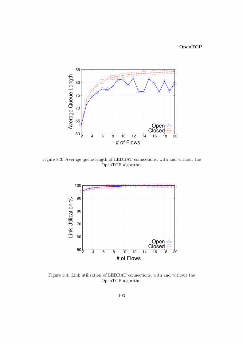
OpenTCP
60
65
70
75
80
85
2 4 6 8 10 12 14 16 18 20
Avera
ge Q
ueue L
ength
# of Flows
OpenClosed
Figure 8.3: Average queue length of LEDBAT connections, with and without theOpenTCP algorithm
50
60
70
80
90
100
2 4 6 8 10 12 14 16 18 20
Lin
k U
tiliz
ation %
# of Flows
OpenClosed
Figure 8.4: Link utilization of LEDBAT connections, with and without theOpenTCP algorithm
103
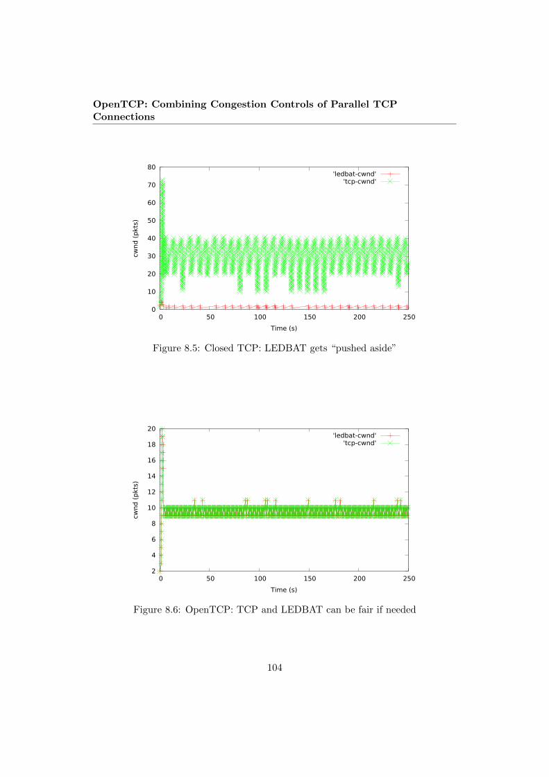
OpenTCP: Combining Congestion Controls of Parallel TCPConnections
0
10
20
30
40
50
60
70
80
0 50 100 150 200 250
cwnd
(p
kts)
Time (s)
'ledbat-cwnd''tcp-cwnd'
Figure 8.5: Closed TCP: LEDBAT gets “pushed aside”
2
4
6
8
10
12
14
16
18
20
0 50 100 150 200 250
cwnd
(p
kts)
Time (s)
'ledbat-cwnd''tcp-cwnd'
Figure 8.6: OpenTCP: TCP and LEDBAT can be fair if needed
104

Conclusion
For the test depicted in Fig. 8.6, we decided that LEDBAT traffic is just asimportant as TCP traffic, giving both connections the same priorities. As we cansee, the cwnd becomes almost exactly equal, at around 10 packets per flow. Notethat the total of 20 packets is smaller than the previously mentioned TCP averageof around 30 in Fig. 8.5. This is because TCP increases its rate until the queueoverflows before reacting. LEDBAT, however, notices increasing delay as soon as thequeue grows and stops increasing its cwnd. Our algorithm notices this reaction and,when used for both TCP and LEDBAT, ensures that none of the connections makethe queue grow. In this way, OpenTCP lets the TCP connection benefit from thegood delay reduction behavior of LEDBAT. Indeed, our tests showed a pronounceddelay reduction when OpenTCP was used while maintaining approximately equalbottleneck utilization in both cases.
8.4 Conclusion
In this paper we have proposed OpenTCP as a method to coordinate the behaviourof multiple TCP connections between the same endpoints. The behavior of multiple“closed” standard TCP connections is very complex and may not behave accordingto the needs of the application. OpenTCP puts the application programmer backin control, and makes it easy to implement open and transparent packet schedulingalgorithms according to the needs of the users.
The experiments reported in this paper show that, with OpenTCP, it is easy toimplement mechanisms that improve the performance of concurrent TCP connec-tions. OpenTCP reduces packet loss and queuing delay. We have also explainedthat it is possible to divide the available bandwidth between the flows according tothe needs of the applications. Hence, in OpenTCP, the application is in full controlof the communication resources.
In future work we will show more examples of the use of OpenTCP, both basedon different underlying TCP-algorithms and on different needs from the applica-tions. We will conduct real-life experiments to prove that OpenTCP can efficientlycontrol several concurrent end-to-end flows.
8.5 Acknowledgment
This work was funded by a collaborative project between the University of Osloand Huawei Technologies Co., Ltd.
105

OpenTCP: Combining Congestion Controls of Parallel TCPConnections
References
[1] Y. Elkhatib, G. Tyson, and M. Welzl, “Can SPDY really make the web faster?”in IFIP Networking 2014 Conference (Networking 2014), Trondheim, Norway,June 2014.
[2] M. Duke, R. Braden, W. Eddy, E. Blanton, and A. Zimmermann, “A Roadmapfor Transmission Control Protocol (TCP) Specification Documents,” RFC7414 (Informational), Internet Engineering Task Force, Feb. 2015, updated byRFC 7805. [Online]. Available: http://www.ietf.org/rfc/rfc7414.txt
[3] K. Ramakrishnan, S. Floyd, and D. Black, “The Addition of ExplicitCongestion Notification (ECN) to IP,” RFC 3168 (Proposed Standard),Internet Engineering Task Force, Sept. 2001, updated by RFCs 4301, 6040.[Online]. Available: http://www.ietf.org/rfc/rfc3168.txt
[4] M. C. Weigle, P. Adurthi, F. Hernandez-Campos, K. Jeffay, and F. D. Smith,“Tmix: A tool for generating realistic TCP application workloads in ns-2,”SIGCOMM Comput. Commun. Rev., vol. 36, no. 3, pp. 65–76, July 2006.[Online]. Available: http://doi.acm.org/10.1145/1140086.1140094
[5] L. Andrew, S. Floyd, and G. Wang, “Common TCP Evaluation Suite,” IETF,Internet-Draft draft-irtf-tmrg-tests-02, July 2009, work in Progress. [Online].Available: https://tools.ietf.org/html/draft-irtf-tmrg-tests-02
[6] B. Briscoe, “Flow rate fairness: Dismantling a religion,” ACM SIGCOMMComputer Communication Review, vol. 37, no. 2, pp. 63–74, Apr. 2007.
[7] M. Welzl, S. Islam, K. Hiorth, and J. You, “TCP in UDP,” InternetEngineering Task Force, Internet-Draft draft-welzl-irtf-iccrg-tcp-in-udp-00,Mar. 2016, work in Progress. [Online]. Available: https://tools.ietf.org/html/draft-welzl-irtf-iccrg-tcp-in-udp-00
[8] S. Ha, I. Rhee, L. Xu, A. Zimmermann, L. Eggert, and R. Scheffenegger,“CUBIC for Fast Long-Distance Networks,” Internet Engineering Task Force,Internet-Draft draft-ietf-tcpm-cubic-01, Jan. 2016, work in Progress. [Online].Available: https://tools.ietf.org/html/draft-ietf-tcpm-cubic-01
[9] H. Balakrishnan, H. S. Rahul, and S. Seshan, “An integrated congestionmanagement architecture for internet hosts,” in Proceedings of the Conferenceon Applications, Technologies, Architectures, and Protocols for ComputerCommunication, ser. SIGCOMM ’99. New York, NY, USA: ACM, 1999, pp.175–187. [Online]. Available: http://doi.acm.org/10.1145/316188.316220
106
References
[10] H. Balakrishnan and S. Seshan, “The Congestion Manager,” RFC 3124(Proposed Standard), Internet Engineering Task Force, June 2001. [Online].Available: http://www.ietf.org/rfc/rfc3124.txt
[11] L. Eggert, J. Heidemann, and J. Touch, “Effects of ensemble TCP,” USC/In-formation Sciences Institute, vol. 7, no. 1, December 1999.
[12] M. Savoric, H. Karl, M. Schlager, T. Poschwatta, and A. Wolisz, “Analysis andperformance evaluation of the EFCM common congestion controller for TCPconnections,” Computer Networks, vol. 49, no. 2, pp. 269–294, 2005.
[13] J. Touch, “TCP Control Block Interdependence,” RFC 2140 (Informational),Internet Engineering Task Force, Apr. 1997. [Online]. Available: http://www.ietf.org/rfc/rfc2140.txt
[14] R. Krishnan, L. Yong, A. Ghanwani, N. So, and B. Khasnabish,“Mechanisms for Optimizing Link Aggregation Group (LAG) and Equal-CostMultipath (ECMP) Component Link Utilization in Networks,” RFC 7424(Informational), Internet Engineering Task Force, Jan. 2015. [Online].Available: http://www.ietf.org/rfc/rfc7424.txt
[15] C. Raiciu, M. Handley, and D. Wischik, “Coupled Congestion Controlfor Multipath Transport Protocols,” RFC 6356 (Experimental), InternetEngineering Task Force, Oct. 2011. [Online]. Available: http://www.ietf.org/rfc/rfc6356.txt
[16] J. Chu, N. Dukkipati, Y. Cheng, and M. Mathis, “Increasing TCP’s InitialWindow,” RFC 6928 (Experimental), Internet Engineering Task Force, Apr.2013. [Online]. Available: http://www.ietf.org/rfc/rfc6928.txt
[17] C. Raiciu, S. Barre, C. Pluntke, A. Greenhalgh, D. Wischik, and M. Handley,“Improving datacenter performance and robustness with multipath tcp,”SIGCOMM Comput. Commun. Rev., vol. 41, no. 4, pp. 266–277, Aug. 2011.[Online]. Available: http://doi.acm.org/10.1145/2043164.2018467
[18] S. Islam, M. Welzl, S. Gjessing, and N. Khademi, “Coupled congestion con-trol for RTP media,” in ACM SIGCOMM Computer Communication Review,vol. 44, no. 4. ACM, 2014, pp. 21–26.
[19] M. Welzl, S. Islam, and S. Gjessing, “Coupled congestion controlfor RTP media,” Internet Draft draft-ietf-rmcat-coupled-cc, work inprogress, Apr. 2016. [Online]. Available: https://tools.ietf.org/html/draft-ietf-rmcat-coupled-cc
107

OpenTCP: Combining Congestion Controls of Parallel TCPConnections
[20] S. Amante, B. Carpenter, S. Jiang, and J. Rajahalme, “IPv6 Flow LabelSpecification,” RFC 6437 (Proposed Standard), Internet Engineering TaskForce, Nov. 2011. [Online]. Available: http://www.ietf.org/rfc/rfc6437.txt
[21] G. Fairhurst, A. Sathiaseelan, and R. Secchi, “Updating TCP to SupportRate-Limited Traffic,” RFC 7661 (Experimental), Internet Engineering TaskForce, Oct. 2015. [Online]. Available: http://www.ietf.org/rfc/rfc7661.txt
[22] S. Shalunov, G. Hazel, J. Iyengar, and M. Kuehlewind, “Low ExtraDelay Background Transport (LEDBAT),” RFC 6817 (Experimental),Internet Engineering Task Force, Dec. 2012. [Online]. Available: http://www.ietf.org/rfc/rfc6817.txt
[23] D. Ros and M. Welzl, “Less-than-best-effort service: A survey of end-to-endapproaches,” Communications Surveys Tutorials, IEEE, vol. 15, no. 2, pp.898–908, 2013.
108
Chapter 9
Single-Path TCP CongestionControl Coupling
Authors. Safiqul Islam (1), Michael Welzl (1), Kristian Hiorth (1), David Hayes(2), Øystein Dale (1), Grenville Armitage (3), Stein Gjessing (1)
Affiliation.
(1) Department of Informatics, University of Oslo, Norway{safiquli, michawe, kristahi, steing, oystedal}@ifi.uio.no
(2) Simula Research Laboratory, Oslo, [email protected]
(3) Swinburne University of Technology, Melbourne, [email protected]
Publication. Under submission.
Abstract. We present ctrlTCP, a method to combine the congestion controls ofmultiple TCP connections between the same pair of hosts. To address the problemthat these TCP connections may not share the same path, they can be encapsu-lated. This is sometimes already done, e.g. for VPNs. For other cases, we proposea method to encapsulate multiple TCP connections within a single UDP port pairwithout incurring header overhead. Different from the previously proposed Con-gestion Manager, our method is designed to minimize the changes to the existingTCP code, making it easier to implement. While we are not the first to proposesuch lighter-weight congestion coupling, prior approaches (E-TCP and EFCM) had
109

Single-Path TCP Congestion Control Coupling
deficiencies that are eliminated in ctrlTCP. Using ns-2 simulations and an implemen-tation in the FreeBSD kernel, we show that our mechanism reduces both queuingdelay and packet loss while enabling precise allocation of the share of the availablebandwidth between the connections according to the needs of the applications.
9.1 Introduction
An increasing number of TCP flows overlap in time and share the same endpoints.There can be many reasons: a client-server application may deliberately establishparallel TCP connections to a server in an attempt to expedite content transfers,independent instances of an application may initiate connections to the same serverthat just happen to overlap in time, and so forth. Unfortunately, as the resultingoverlapping TCP connections usually share a common network path, they can sub-optimally interact (and indeed, compete) with each other and other flows. Combina-tions that appear to produce throughput gains will often drive significant additionalqueuing delays or packet losses, to the detriment of unrelated flows sharing any bot-tlenecks along the common path. In large part this is due to each overlapping TCPconnection’s congestion control state machines acting independently.
Significant solutions to date fall into one of two classes: Merge common application-layer data streams above a single transport layer connection, or couple the transportlayer congestion control machinery for connections known to share the same end-points. Examples of the former include SPDY [1] and HTTP/2 [2], which multiplexmultiple web sessions on top of a single TCP connection between client and server.Examples of the latter, often referred to as coupled congestion control, include theCongestion Manager (CM [3]), Ensemble TCP (E-TCP [4]) and Ensemble FlowCongestion Management (EFCM [5]).
However, there are known problems within each class of solutions. Simply mul-tiplexing application flows onto a single TCP connection results in a head-of-line(HoL) blocking, where faster application-layer threads are forced to wait while se-rialized messages from slower threads are handled at the TCP destination. Solv-ing HoL blocking usually involves entirely different transport protocols, such asQUIC [6] or SCTP [7]. On the other hand, previous coupled congestion controlstrategies tend not to fully leverage the statefulness of the TCP congestion controlalgorithm.
Our novel contribution in this paper is two-fold: We introduce ctrlTCP, a refinedcoupled congestion control strategy that better utilizes a TCP sender’s awareness ofnetwork conditions and allows precise intra-flow bandwidth sharing. and we couplethis with a light-weight, dynamically configured TCP-in-UDP (TiU) encapsulationscheme that ensures our coupled flows do indeed share all bottlenecks along a singlepath. TiU is optional, as our coupled congestion control strategy is applicablewherever overlapping TCP flows must follow the same path (such as when routed
110

Coupled congestion control algorithm design
over a VPN tunnel).
Using both ns-2 and FreeBSD implementations we have explored the benefits ofour coupled congestion control scheme and TiU encapsulation. Our results demon-strate significantly better (lower) queuing delays and packet loss rates compared touncoupled TCP connections. We believe our approach is practical and deployable intoday’s Internet, offering lower RTTs to all traffic sharing bottlenecks with coupledTCP connections.
The rest of our paper is organized as follows: Section 9.2 introduces relatedwork and describes our improved approach to coupled TCP congestion control. Wediscuss methods to ensure that coupled flows really traverse the same bottleneck inSection 9.4, and present simulations and experimental results in Section 9.3. Thepaper concludes in Section 9.5.
9.2 Coupled congestion control algorithm design
Despite a number of previous attempts at coupled congestion control, widespreaddeployment has proven to be difficult, mainly due to the complexities of the pro-posed mechanisms. We first briefly outline key prior work as motivation for ourproposed mechanism.
9.2.1 Prior Work
To the best of our knowledge, RFC 2140 [8] is the first work to outline a mechanismfor coupling TCP connections by sharing TCP Control Block (TCB) in order tobetter initialize new connections. This idea was expanded by Ensemble TCP (E-TCP) [4] to allow concurrent flows to benefit from each other beyond initialization,working together so that the aggregate is no more aggressive than a single TCPflow. On the other hand, Ensemble Flow Congestion Management (EFCM) [5]allows the aggregate to be collectively as aggressive as the combination of separatelycontrolled TCP connections. The Congestion Manager (CM) [3, 9] takes the concepteven further, completely replacing each flow’s congestion controller with its owncongestion control mechanism—a rate based controller.
The CM is a major modification to the implementation of congestion controlas part of TCP. Our proposal aims to minimize changes to the kernel TCP code,making it much easier to implement as an add-on, closer in spirit to E-TCP andEFCM, but fixing problems that we find with these mechanisms. We adopt amethod that we earlier used to couple congestion control for media flows in WebRTC[10, 11]. However, TCP has particular difficulties due to its stateful nature, requiringa significantly different design approach for ctrlTCP.
Congestion control coupling as described here shares some similarities, yet alsohas important differences, when compared to coupled congestion control for Multi-
111

Single-Path TCP Congestion Control Coupling
Path TCP (MPTCP), e.g. the mechanisms LIA [12], OLIA [13] and BALIA [14].Similar to our proposal, E-TCP and the CM, these mechanisms try to behave likeone flow across a single bottleneck. However, MPTCP’s coupling assumes that flowsshould take a different path, and ideally also traverse different bottlenecks. Thismeans that some things that single-path coupling can do would probably be quiteinappropriate for MPTCP. For example with single-path coupling:
− A new connection joining the aggregate can immediately get a share of thepotentially quite large cwnd of ongoing transfers. This can significantly reducethe completion time of short flows, but in MPTCP, it results in using a verylarge initial window on a new path.
− Changing states (e.g. avoiding slow start), as our algorithm does, stronglyrelies on the assumption that there is only a single shared bottleneck. Theresulting behaviour is quite wrong in case of multiple bottlenecks.
− A share of the aggregate cwnd can be assigned based on application preferencein the case of single-path coupling. These preferences can even change on thefly. Again, if connections would traverse different paths, the outcome on thewire could temporarily be much more aggressive than TCP.
Finally, MPTCP’s subflows also use different tuples in order to be able to usedifferent paths – this is, for example, leveraged in [15] without even using multi-homed end-systems. This is the opposite of what we are trying to achieve with theUDP encapsulation discussed in Section 9.4.
9.2.2 Basic algorithm logic
In ctrlTCP, each TCP session communicates with an entity called a Coupled Con-gestion Controller (CCC). The CCC couples flows traversing the same path to thesame destination. Fig. 9.1 provides an overview of this communication. New TCPsessions first register with the CCC, supplying it with a (i) connection identifier(cid), (ii) Priority (P), (iii) cwnd, and (iv) ssthresh. Where necessary a new cou-pled group is created and all summation values are initialized; this includes settingcommon variables such as the sum of all congestion windows, sum cwnd. Thenthe new flow obtains its first cwnd and ssthresh values. Algorithm 5 describes theregistering process. Table 9.1 defines the variables used in Algorithms 5 to 7.
Once flows are coupled in a group, they update their status each time theychange cwnd. The update message includes cid, cwnd, sshthresh, and the TCPstate machine state. The CCC sends a response assigning the updating connectioncalculated values of cwnd and ssthresh. The update algorithm, summarized in Al-gorithm 7, emulates the behavior of a single TCP session by choosing one session asthe Coordinating Connection (CoCo), initially the first flow. This session dictates
112
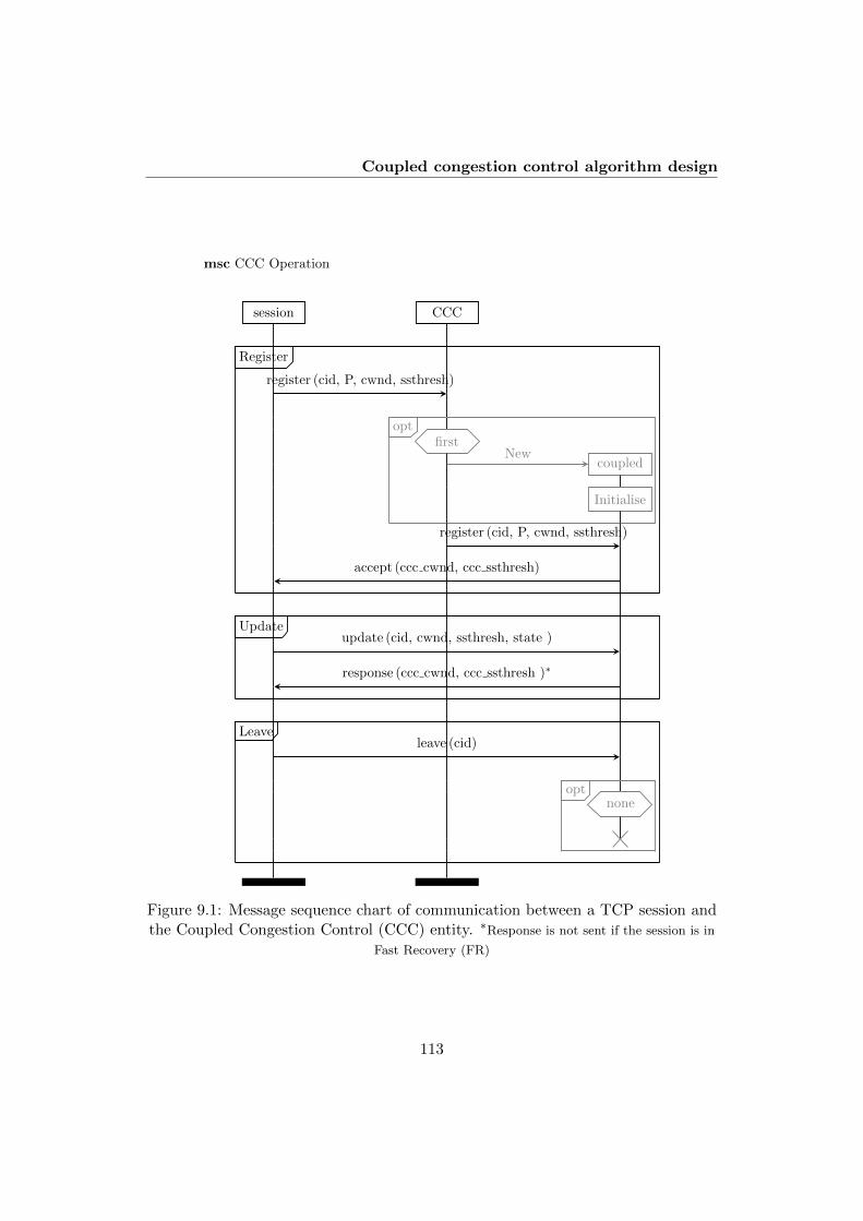
Coupled congestion control algorithm design
session CCC
register (cid, P, cwnd, ssthresh)
first
coupledNew
Initialise
opt
register (cid, P, cwnd, ssthresh)
accept (ccc cwnd, ccc ssthresh)
Register
update (cid, cwnd, ssthresh, state )
response (ccc cwnd, ccc ssthresh )∗
Update
leave (cid)
noneopt
Leave
msc CCC Operation
Figure 9.1: Message sequence chart of communication between a TCP session andthe Coupled Congestion Control (CCC) entity. ∗Response is not sent if the session is in
Fast Recovery (FR)
113

Single-Path TCP Congestion Control Coupling
Algorithm 5 CCC – connection registering
1: Input: cid, cwnd, ssthresh, P2: Output: ccc cwnd(cid), ccc ssthresh(cid)3: if first connection in new coupled group then4: ccc cwnd(cid) ← cwnd5: sum P ← 06: sum cwnd ← 07: sum ssthresh ← 08: end if9: ccc P(cid) ← P
10: sum P ← sum P + P11: sum cwnd← sum cwnd + cwnd12: ccc cwnd(cid) ← P × sum cwnd / sum P13: ccc ssthresh(cid) ← ssthresh14: if sum ssthresh > 0 then15: ccc ssthresh(cid) ← P × sum ssthresh / sum P16: end if17: Send ccc cwnd(cid) and ccc ssthresh(cid) to cid
the increase / decrease behavior for the aggregate. For simplicity, the algorithmrefrains from adjusting cwnd when a connection is in Fast Recovery (FR). As wewill explain in the following, we limit the usage of Slow Start (SS), ensuring thatthe aggregate’s behavior is only dictated by SS when all connections are in the SSphase. A detailed description of Algorithm 7 is provided in the appendix.
When a TCP session terminates (see Algorithm 6) its variables are removed andthe summations are recalculated. The common variables also need to be adjustedwhen a flow leaves, as shown in Algorithm 6. If it is the last connection in thecoupled group, the group is removed from the CCC.
Our algorithm shares state variables across multiple TCP connections. Thishas been done in the past by E-TCP [4] and EFCM [5]; however, these works donot account for the stateful nature of TCP, leading to erroneous behavior if, aswith E-TCP and our algorithm, the goal is to emulate the dynamics of a singleTCP connection. In the following, we use these two schemes to explain the designrationale underlying our algorithm, and we accordingly contrast our work againstthem in Section 9.3.
114

Coupled congestion control algorithm design
Algorithm 6 CCC – connection leaving
1: Input: cid2: if last connection then3: Remove coupled group4: else5: if cid = CoCo then6: Coco ← the next connection7: end if8: sum P ← sum P - ccc P(cid)9: Remove ccc P(cid), ccc cwnd(cid), ccc ssthresh(cid)
10: end if
9.2.3 Loss events
Fast recovery behaviour
The algorithm only decides when a flow should enter Fast Recovery (FR); while moreelaborate strategies are possible, incorporating the FR phase itself in the algorithmwould have made it significantly more complex and did not seem necessary. Thus,once a flow is in FR, we refrain from updating the cwnd and ssthresh values.
TCP operates on loss events (one or more packet losses per RTT), not indi-vidual packet losses. When congestion controls are combined, this logic should bepreserved. We explain this by using an example of two connections traversing thesame bottleneck. A single packet drop from connection 1, two drops from connec-tions 1 and 2 or multiple packet drops from connection 2 only, should all result inthe same behavior of the traffic aggregate. Simply sharing TCP variables such ascwnd or ssthresh cannot achieve this.
We simulated the behaviour of two TCP Reno connections in the ns-2 simula-tor1 using a dumbbell topology (bottleneck capacity 10 Mbps, RTT 100 ms, packetsize 1500 bytes, and queue length of one BDP (83 packets)), in order to compareour mechanism with EFCM coupling2 and without coupling. Fig. 9.2 captures thebehavior of two TCP Reno flows, without coupling, with EFCM, and with our pro-posed coupled congestion control mechanism, respectively. We artificially induceda packet drop for connection 1 at 25 seconds. Fig. 9.2(a) shows that without cou-pling, it takes quite some time to converge, and with EFCM (see Fig. 9.2(b)), theaggregate is not halved, and the flows remain aggressive. This can lead to higherqueue growth and packet losses.
1We used the TCP-Linux module that gives the flexibility to use the actual Linux TCP code insimulations. In our case, it was Linux kernel 3.17.4
2We implemented EFCM and E-TCP in ns-2 based on the description from [5] and [4].
115

Single-Path TCP Congestion Control Coupling
Variable Description
cid Connection identifier
cwnd TCP session congestion window value
ssthresh TCP session slow start threshold value
P Priority weight of a TCP flow
ccc var Coupled congestion controller calculated versionof a TCP session variable
sum cwnd Sum of all the cwnd values in the group
sum ssthresh Sum of all the ssthresh values in the group
sum P Sum of all the priority values in the group
state TCP state machine state: Slow Start (SS), orCongestion Avoidance (CA), or Fast Recovery(FR)
ssbits Bit array with a bit for each connection in thegroup. Set if connection state=SS
CoCo Coordinating Connection
Table 9.1: Names of variables used in Algorithms 5 to 7
Timeouts and Slow Start
The algorithm operates on the principle that slow start following a timeout shouldonly happen if no packets could be delivered across the same path for the timeoutinterval. This assumption is broken if some but not all connections experience atimeout. In practice this means that if at least one of the flows is still receivingacknowledgements and has not tried to enter slow start, then it is not appropriatefor the coupled group to enter slow start. The variable ssbits is used to facilitatethis decision (see Algorithm 7).
E-TCP does not adopt this rationale, instead forcing all flows to slow start ifany one has a timeout (see Fig. 9.2(c) where we artificially induced a timeout forconnection 1 to simulate this behavior). EFCM has the issue of sharing the initialvery large ssthresh value, which potentially moves all existing flows back into SlowStart from Congestion Avoidance when a new flow joins.
With our algorithm, if the timeout of a particular flow is indeed due to lostpackets, it will recover the lost packets when it enters Fast Recovery. In the extremecase when a flow has lost its entire cwnd of packets, it can take up to 1+Dupthresh3
RTTs for the flow to enter fast recovery. The reason for this is that the flow’sduplicate ack counter is not being incremented for ACKs received on other coupledflows, as would be the case if it was truly one aggregated TCP flow. A possible
3Number of duplicate ACKs required to trigger fast recovery
116

Coupled congestion control algorithm design
20 25 30 35 40 45Time (s)
20
30
40
50
60
70
80
90
100
110
cwnd
(pac
kets
)
1 loss
Connection 1Connection 2
(a) Not coupled
20 25 30 35 40 45Time (s)
20
30
40
50
60
70
80
90
100
110
cwnd
(pac
kets
) 1 loss
Connection 1Connection 2
(b) Coupled with EFCM
15 20 25 30 35 40 45Time (s)
0
20
40
60
80
100
cwnd
(pac
kets
)
SS for both upon timeout
Connection 1Connection 2
(c) Coupled with E-TCP
20 25 30 35 40 45Time (s)
20
30
40
50
60
70
80
90
100
110cw
nd(p
acke
ts) 1 loss
Connection 1Connection 2
(d) Coupled with ctrlTCP
Figure 9.2: cwnd of two TCP Reno flows
solution to this — currently under investigation — is to count ACKs from othercoupled flows and send this DupACK count when the affected flow sends its update.This will allow fast recovery to be triggered after just 1 RTT and still maintainsthe simplicity of implementation and interaction with the coupled flows that ouralgorithm has.
9.2.4 ACK-clocking
When a new connection joins, it may benefit from sharing the large cwnd of existingflows. This has potential to cause bursts of transmission into the network, unlessthe packets are paced in some way. Consider the scenario where connection 1 hasalready achieved a cwnd of 100 packets, connection 2 joins and receives cwnd=50packets as its share of the capacity. If it sends these without some form of pacingit can cause a significant congestion spike in the network. It is not a problem forconnection 1 alone because its packets are paced by arriving ACKs.
Our CCC algorithm uses a simple ack-clocking mechanism to avoid these bursts.
117

Single-Path TCP Congestion Control Coupling
0
20
40
60
80
100
120
140
5.1 5.2 5.3 5.4 5.5
Packet sequence n
um
ber
Time (s)
(a) Packet sequence diagram of connection 2,without ack-clocking
0
20
40
60
80
100
120
140
160
5.1 5.2 5.3 5.4 5.5
Packet sequence n
um
ber
Time (s)
(b) Packet sequence diagram of connection 2,with ack-clocking
5 10 15 20 25 30Time (s)
0
20
40
60
80
100
120
140
cwnd
(pac
kets
)
Connection 1Connection 2
(c) cwnd over time of two coupled-TCPconnections, without ack-clocking
5 10 15 20 25 30Time (s)
0
20
40
60
80
100
120
140
cwnd
(pac
kets
)
Connection 1Connection 2
(d) cwnd over time of two coupled-TCPconnections, with ack-clocking
Figure 9.3: Coupling of 2 flows when flow 2 joins after 5 seconds. Packet sequenceplots and cwnd plots are shown with and without the use of ack-clocking
mechanism
Rather than using timers, we utilize the acknowledgements connection 1 receives topace the sending of connection 2 over the course of the first RTT. In this way, weavoid causing a congestion spike in the network.
Fig. 9.3 shows the packet sequence diagrams and cwnd plots over time of twocoupled-TCP Reno connections, with and without ack-clocking. Without ack-clocking, the congestion spike causes significant packet loss. Our ack clocking algo-rithm completely eliminates this issue.
118

Results
CORE emulator
Sender
Generator
Router A Router B
Sink
Receiver
Crosstraffic
50ms 10 Mbps 50ms
Figure 9.4: Emulated testbed topology
9.3 Results
We have implemented our mechanism in the ns-2 simulator and in the FreeBSD11 kernel. Fig. 9.4 shows the experimental setup for both the ns-2 and emulationexperiments. For ns-2 we used TMIX4 produced background traffic in the ns-2simulator. We used a pre-processed version of TMIX traffic in order to provide anapproximate load of 50% on a 10 Mbps bottleneck link. The RTTs of backgroundTCP flows generated by TMIX are in the range of 80 - 100 ms. For the emula-tion experiments the sender and receiver machines are physical, identical desktopcomputers (Intel i7-870 2.93GHz CPU, 8GB RAM) equipped with Gigabit Ether-net Network Interface Cards (NICs), running our modified version of FreeBSD-11.They are connected via a third identical machine running Ubuntu Linux 15.04 andthe CORE network emulator [18] version 4.7 to form the dumbbell topology inFig. 9.4 (bottleneck capacity 10 Mbps, RTT 100 ms, MTU 1500 bytes, and queuelength 1 BDP (83 packets)). The underlying TCP congestion control mechanism isNewReno.
In order to compare our proposed coupling mechanism with E-TCP and EFCM,we simulated the behavior of two TCP Reno connections by varying the number oftimeouts. We achieved this by dropping a series of packets (per provoked timeout)from only one of the flows. Fig. 9.5 illustrates the aggregate throughput of twoTCP Reno connections, with EFCM, E-TCP, and ctrlTCP, respectively. It can beseen from the graph that the aggregate throughput of two connections coupled withEFCM is more than ctrlTCP and E-TCP because it is more aggressive than oneflows. However, the aggregate throughput of two connections coupled with ctrlTCP
4TMIX traffic used in ns-2 simulations is taken from 60-minute trace of campus trafficat the University of North Carolina [16] traffic in ns-2 simulations, and it can be accessedfrom the common TCP evaluation suite [17].
119

Single-Path TCP Congestion Control Coupling
1 2 3 4No of timeouts
4
5
6
7
8
9
10
Thro
ughp
utof
2flo
ws
(Mbp
s) ctrlTCPE-TCPEFCM
Figure 9.5: Throughput of 2 flows, for ctrlTCP, E-TCP, and EFCM whileincreasing the number of timeouts
is more than E-TCP because our mechanism does not force all flows to enter slowstart if one has a timeout. Because this result, together with the findings in Fig. 9.2,shows that ctrlTCP successfully eliminates the deficiencies of EFCM and E-TCP,we do not consider these two algorithms further.
Fig. 9.6 showcases an example of ctrlTCP where two connections are createdwith priorities 0.75 and 0.25, respectively. Connection 1 starts at t=3 sec and con-nection 2 starts at t=30 sec. It can be seen from Fig. 9.6 that between t=30 sec andt=85 sec (the duration when two flows coexist), flow 1 gets 3/4 of the aggregatecwnd while flow 2 gets 1/4. It is also observable that the two flows are coupled, asthey increase and decrease their cwnds at the same time. Outside of this interval,flow 1 gets all of the cwnd.
In Fig. 9.6, flow 2 is able to immediately use its share of the aggregate cwnd.Fig. 9.7 demonstrates that this can yield a significant improvement in the shortflow’s completion time. Here, we varied the capacity from 1 Mbps to 10 Mbps. Werepeated this test 10 times with randomly picked flow start times over the firstsecond for the long flow (25 Mb) and the sixth second for the short flow (200 Kb).It can be seen from Fig. 9.7 that ctrlTCP with ack-clocking further improves theshort flow’s FCT. Coupling also removes a synchronization effect: in the uncou-pled 2 Mbps scenario, the short flow was even faster than in the 3 Mbps scenariobecause it was the first to send its initial window (IW) into the queue, which did
120
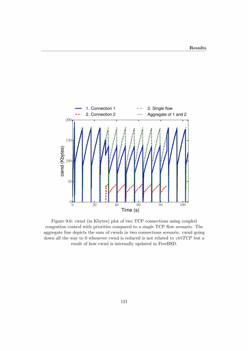
Results
0 20 40 60 80 100
Time (s)
0
50
100
150
200
cwnd
(Kby
tes)
1. Connection 12. Connection 2
3. Single flowAggregate of 1 and 2
Figure 9.6: cwnd (in Kbytes) plot of two TCP connections using coupledcongestion control with priorities compared to a single TCP flow scenario. The
aggregate line depicts the sum of cwnds in two connections scenario. cwnd goingdown all the way to 0 whenever cwnd is reduced is not related to ctrlTCP but a
result of how cwnd is internally updated in FreeBSD.
121

Single-Path TCP Congestion Control Coupling
0 2 4 6 8 10Capacity (Mbps)
0
10
20
30
40
50
60
70
80
90FC
Tof
shor
tflow
s(R
TTs)
1. Short flow2. Short flow - coupled (no-ack-clock)3. Short flow - coupled (ack-clocked)
Figure 9.7: Flow completion time (FCT) of short flows, with and withoutack-clocking (simulation)
not have enough space for the IWs of two flows. We also confirm the reduction ofFCTs in emulation while varying the capacity to 6, 8, and 10 Mbps, respectively(see Fig. 9.8). In both the simulation and emulation experiments, the impact onthe long flow was negligible.
In the following tests, experiments were repeated 10 times with different ran-domly picked flow start times over the first second. Prerecorded traces of self-similarcrosstraffic were injected to occupy 50% of the bottleneck link capacity on average.These were generated using the D-ITG [19] traffic generator, by superposition of 11on/off streams, with Pareto heavy-tailed on-time distributions (H = 0.8) and expo-nentially distributed off-times (µ ∈ [1, 2] s). Packet sizes are normally distributed(µ = 1000, σ = 200), with exponentially distributed (µ ∈ [50, 150] pps) inter-packettimes.
Fig. 9.9 and 9.11 illustrate the average RTT, and loss ratio, with and withoutcoupling, respectively. It can be seen from the graphs that our mechanism reducesboth the average RTT and loss without significantly affecting goodput as we variedthe number of flows (see Fig. 9.10).
Fig. 9.12 demonstrates that our mechanism can distribute the share of the ag-gregate cwnd to the TCP connections based on the needs of the applications. Both
122

Encapsulation
0 5 10 15 20 25 30 35
FCT (s)
6
8
10
Cap
acity
(Mb)
Long Flow (uncoupled)Short Flow (uncoupled)
Long Flow (coupled)Short Flow (coupled)
Figure 9.8: Flow completion time (FCT) of short flows without ack-clocking(emulation)
the simulation and emulation results confirm that our mechanism calculates and as-signs the shares as we vary the priority ratio between two TCP Reno connections,close to the ideal behaviour.
In order to see if our mechanism could be run as a stand-alone application tocontrol different senders not running on the same OS instance, we have also imple-mented our ctrlTCP in the FreeBSD 11 kernel with state shared across the freelyavailable VirtualBox5 hypervisor. In this way, it could be used to prevent an unfairsender from obtaining a larger share of the capacity by opening multiple TCP con-nections. Fig. 9.13 shows Jain’s Fairness Index [20] ( (
∑Ni=1 xi(t))
2/N∑N
i=1 xi(t)2
) for N = 2 aggregate flows x1 and x2, calculated using the traffic that originatedfrom two VMs across a 10 Mbit/s×100 ms bottleneck with and without the coupledcongestion control algorithm in Section 9.2.
9.4 Encapsulation
Our algorithm, as well as EFCM, E-TCP and the CM assume that multiple TCPconnections sending to the same destination would traverse the same bottleneck.This is not always true – load-balancing mechanisms such as Link Aggregation
5https://www.virtualbox.org
123

Single-Path TCP Congestion Control Coupling
Figure 9.9: Average delay (in milliseconds) as the number of TCP connections isvaried, with and without coupled congestion control (emulation)
Figure 9.10: Average goodput as the number of TCP connections is varied, withand without coupled congestion control (emulation)
124

Encapsulation
Figure 9.11: Loss ratio as the number of TCP connections is varied, with andwithout coupled congestion control (emulation)
Figure 9.12: Throughput ratio as the priorities of two TCP connections are varied
125

Single-Path TCP Congestion Control Coupling
1:1 1:2 1:3 1:4
Flows ratio (VM1:VM2)
0.70
0.75
0.80
0.85
0.90
0.95
1.00Fa
irnes
sin
dex
ctrlTCPuncoupled
Figure 9.13: Fairness between two VMs, with 1 flow in VM1 and 1 to 4 flows inVM2. Without coupling, fairness deteriorates; our ctrlTCP algorithm achieves
perfect fairness.
Group (LAG) and Equal-Cost Multi-Path (ECMP) may force them to take dif-ferent paths [21]. If this leads to the connections seeing different bottlenecks,combining the congestion controllers would incur wrong behavior (as discussed inSection 9.2.1). There are, however, several application scenarios where the single-bottleneck assumption is correct:
− Whenever all traffic between the two hosts is already tunneled, e.g. for VPNs.There are many possible encapsulation schemes for various use cases. For ex-ample, Generic UDP Encapsulation (GUE) [22] — a method already deployedin Linux — allows us to multiplex several TCP connections onto a same UDPport number pair. Several encapsulation methods transmit layer-2 framesover an IP network – e.g. VXLAN [23] (over UDP/IP) and NvGRE [24](over GRE/IP). Because Layer-2 networks should be agnostic to the trans-port connections running over them, the path should not depend on the TCPport number pair and our algorithm should work. Some care must still betaken: for example, for NvGRE, [24] says: “If ECMP is used, it is RECOM-MENDED that the ECMP hash is calculated either using the outer IP framefields and entire Key field (32 bits) or the inner IP and transport frame fields”.If routers do use the inner transport frame fields (typically, port numbers) forthis hashing, we have the same problem even over NvGRE.
− When IPv6 is available, the TCP connections could be assigned the same IPv6flow label. According to RFC 6437 [25], “The usage of the 3-tuple of the FlowLabel, Source Address, and Destination Address fields enables efficient IPv6flow classification, where only IPv6 main header fields in fixed positions areused” – this would be favorable for TCP congestion control coupling. However,this RFC does not end up making a clear recommendation about either using
126

Encapsulation
the 3-tuple or 5-tuple (which includes the port numbers) – it seems that bothmethods are valid. Thus, whether it works to use the flow label as the solemeans to put connections on the same path depends on router configuration.When it works, it is an attractive option because it does not require changingthe receiver.
− Because TCP does not preserve message boundaries and the size of the TCPheader can vary depending on the options that are used, it is also no problemto use methods that insert a header in between the TCP header and the UDPpacket with a (e.g. SPUD [26]) without exceeding the known MTU limit.When creating a TCP segment, a TCP sender needs to consider the length ofthis header when calculating the segment size, just like it would consider thelength of a TCP option. This assumes that the usage of other headers suchas SPUD in-between the UDP header and the TiU header is known to boththe sender-side and receiver-side code that processes TiU.
− Measurements can infer whether flows traverse the same bottleneck. This evenallows to combine flows from the same sender that are destined for differentreceivers. A recent Shared Bottleneck Detection (SBD) tool [27, 28] wassuccessfully applied to MPTCP in [29]. Such a dynamic decision about sharedbottlenecks requires that ctrlTCP can be enabled or disabled, which is easydue to its design but much harder with the Congestion Manager.
− Whenever the network configuration is known.
We want to be able to ensure that TCP congestion control coupling can alwayswork, provided that the required code is available at the receiver – and be able toefficiently fall back to the standard behaviour in case it is not. To achieve this, wehave devised a method to encapsulate multiple TCP connections using the sameUDP port pair. We have implemented this for both the sender and receiver in theFreeBSD kernel, as a simple add-on to the TCP implementation that is controlledvia a socket option.
9.4.1 TCP-in-UDP (TiU)
We propose a TCP-in-UDP (TiU) encapsulation method, inspired by [30] and [31],where a UDP header is followed by a slightly altered TCP header. The UDPsource ports and destination ports are semantically different than [30] and [31]:multiple TCP connections use the same well known UDP port in our case. Toavoid increasing the MSS, we removed redundant fields, such as the checksum, theTCP source and destination ports, and the urgent pointer. However, to identify theconnections we replaced reserved bits and urgent flags with a five-bit Connection IDfield. The Connection ID is a way to uniquely identify a port number pair of a TCP
127
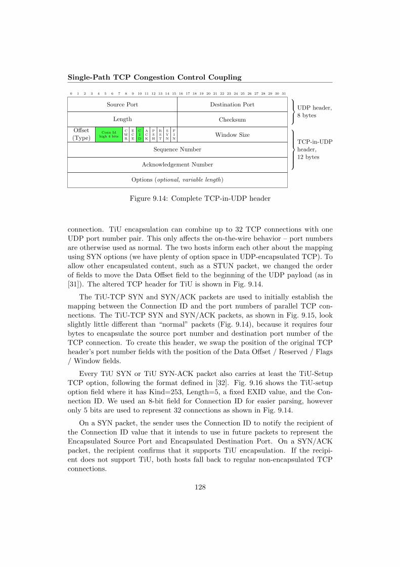
Single-Path TCP Congestion Control Coupling
0 1 2 3 4 5 6 7 8 9 10 11 12 13 14 15 16 17 18 19 20 21 22 23 24 25 26 27 28 29 30 31
Source Port Destination Port
Length Checksum
UDP header,8 bytes
Offset(Type)
Conn Idhigh 4 bits
CWR
ECE
CID
ACK
PSH
RST
SYN
FIN
Window Size
Sequence Number
Acknowledgement Number
TCP-in-UDPheader,12 bytes
Options (optional, variable length)
Figure 9.14: Complete TCP-in-UDP header
connection. TiU encapsulation can combine up to 32 TCP connections with oneUDP port number pair. This only affects the on-the-wire behavior – port numbersare otherwise used as normal. The two hosts inform each other about the mappingusing SYN options (we have plenty of option space in UDP-encapsulated TCP). Toallow other encapsulated content, such as a STUN packet, we changed the orderof fields to move the Data Offset field to the beginning of the UDP payload (as in[31]). The altered TCP header for TiU is shown in Fig. 9.14.
The TiU-TCP SYN and SYN/ACK packets are used to initially establish themapping between the Connection ID and the port numbers of parallel TCP con-nections. The TiU-TCP SYN and SYN/ACK packets, as shown in Fig. 9.15, lookslightly little different than “normal” packets (Fig. 9.14), because it requires fourbytes to encapsulate the source port number and destination port number of theTCP connection. To create this header, we swap the position of the original TCPheader’s port number fields with the position of the Data Offset / Reserved / Flags/ Window fields.
Every TiU SYN or TiU SYN-ACK packet also carries at least the TiU-SetupTCP option, following the format defined in [32]. Fig. 9.16 shows the TiU-setupoption field where it has Kind=253, Length=5, a fixed EXID value, and the Con-nection ID. We used an 8-bit field for Connection ID for easier parsing, howeveronly 5 bits are used to represent 32 connections as shown in Fig. 9.14.
On a SYN packet, the sender uses the Connection ID to notify the recipient ofthe Connection ID value that it intends to use in future packets to represent theEncapsulated Source Port and Encapsulated Destination Port. On a SYN/ACKpacket, the recipient confirms that it supports TiU encapsulation. If the recipi-ent does not support TiU, both hosts fall back to regular non-encapsulated TCPconnections.
128
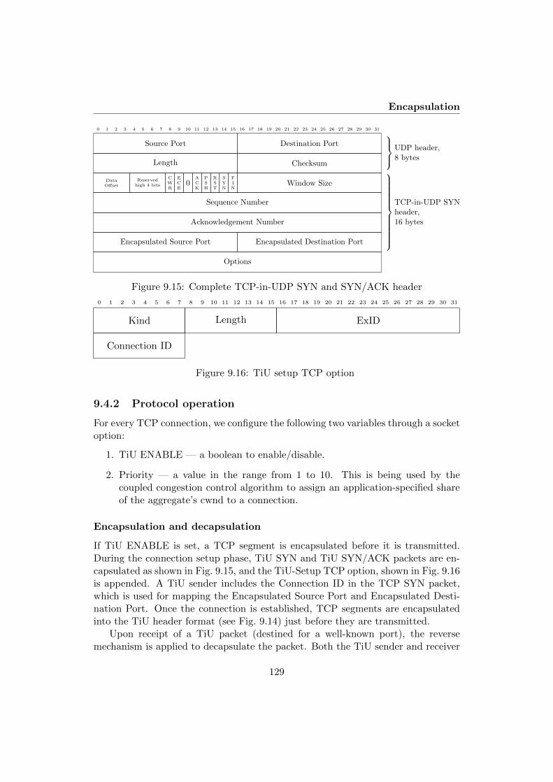
Encapsulation
0 1 2 3 4 5 6 7 8 9 10 11 12 13 14 15 16 17 18 19 20 21 22 23 24 25 26 27 28 29 30 31
Source Port Destination Port
Length Checksum
UDP header,8 bytes
DataOffset
Reservedhigh 4 bits
CWR
ECE
0ACK
PSH
RST
SYN
FIN
Window Size
Sequence Number
Acknowledgement Number
Encapsulated Source Port Encapsulated Destination Port
TCP-in-UDP SYNheader,16 bytes
Options
Figure 9.15: Complete TCP-in-UDP SYN and SYN/ACK header
0 1 2 3 4 5 6 7 8 9 10 11 12 13 14 15 16 17 18 19 20 21 22 23 24 25 26 27 28 29 30 31
Kind Length ExID
Connection ID
Figure 9.16: TiU setup TCP option
9.4.2 Protocol operation
For every TCP connection, we configure the following two variables through a socketoption:
1. TiU ENABLE — a boolean to enable/disable.
2. Priority — a value in the range from 1 to 10. This is being used by thecoupled congestion control algorithm to assign an application-specified shareof the aggregate’s cwnd to a connection.
Encapsulation and decapsulation
If TiU ENABLE is set, a TCP segment is encapsulated before it is transmitted.During the connection setup phase, TiU SYN and TiU SYN/ACK packets are en-capsulated as shown in Fig. 9.15, and the TiU-Setup TCP option, shown in Fig. 9.16is appended. A TiU sender includes the Connection ID in the TCP SYN packet,which is used for mapping the Encapsulated Source Port and Encapsulated Desti-nation Port. Once the connection is established, TCP segments are encapsulatedinto the TiU header format (see Fig. 9.14) just before they are transmitted.
Upon receipt of a TiU packet (destined for a well-known port), the reversemechanism is applied to decapsulate the packet. Both the TiU sender and receiver
129

Single-Path TCP Congestion Control Coupling
remember the mapping of encapsulated port pair. An error message, with a specialvalue 255, is sent to the TiU sender on TiU SYN/ACK packet if the connection IDis not free. This informs the sender to stop encapsulating further TCP segments.
Based on the aforementioned implementation details, a TiU sender operates asfollows, assuming a client connects to a server (listening to a well-known port), andno prior connections have been established between them:
1. Through a socket option, an application requests a TiU operation. The kernelappends the TiU-Setup option to the TiU TCP SYN, which contains Encap-sulated Port numbers (source port A) and the connection ID Z.
2. Upon receiving a packet, the server translates the header back to normalTCP format and gives the resulting TCP packet to regular TCP processing.It associates future TiU packets with connection ID Z to port A. After that,the server responds with TiU SYN-ACK.
3. Upon successful TiU handshaking, packets are encapsulated with a TiU headerbefore sending, and decapsulated upon receiving. Henceforth, both the serverand client use a local identifier to match encapsulated ports from TiU packets,carrying Connection ID Z.
4. After this, if an application wants to open another connection to the samedestination host, it performs the above steps.
5. Now, upon a successful TiU handshake, the coupled congestion control mech-anism is activated as there are two or more connections available.
We implemented a fall-back mechanism (see Fig. 9.17) to cater for unsuccessfulTiU handshakes, e.g. connection ID collisions. This allows to immediately switchto “raw” TCP communication by making TCP SYN and SYN/ACK visible to themiddleboxes: It has been shown in [33] that, since middleboxes keep track of TCPconnections, it may be problematic for connections to fall back to raw TCP packetswithout using a raw TCP SYN and SYN/ACK. The fall-back mechanism works asfollows, assuming a client tries to open a connection to a server:
− A client sends a TiU SYN packet followed by a raw TCP packet.
− The server responds with TiU SYN/ACK, and then sends out a raw TCPSYN/ACK packet (ideally, in that sequence).
− The server immediately stores the associated encapsulated port numbers andConnection ID after receiving a TiU SYN packet and responding with a TiUSYN/ACK packet (and raw TCP SYN/ACK packet). Upon successful TiUhandshakes, it further ignores any additional incoming TCP SYN or TCP
130

Conclusions
Initiator Listener
TiU SYN CID=n cache(TiU capable)
TCP SYN Ignored
TiU SYN-ACK CID=nTiU confirmed
TCP SYN-ACKFor middleboxes
TiU ACK
msc TiU SYN first
Figure 9.17: TCP-in-UDP Happy Eyeballs
SYN/ACK packets from the same host. Otherwise, it normally processesTCP SYN or TCP SYN/ACK packets.
9.5 Conclusions
It is increasingly common for standard TCP connections to overlap in time betweenthe same network endpoints. The result is competition, rather than cooperation,between each connection’s congestion control mechanism, often leading to undesir-able spikes in queuing delay and packet loss rates.
Our paper has made two novel contributions. First, we have introduced ctrlTCP,a new coupled congestion control strategy that allows applications to exert preciseallocation over the relative bandwidth share offered to coupled flows, with onlyminimal interfacing to the kernel TCP code. Second, we have designed a new TCP-in-UDP (TiU) encapsulation scheme that establishes on-demand tunnels for up to32 coupled TCP flows between any two UDP ports on the common endpoints. TiUtunnels ensure our coupled TCP flows always share the same path, regardless of anyflow-aware load-balancing (or similar devices) that might otherwise cause individualTCP flows to take different paths between the same endpoints.
We have implemented ctrlTCP and TiU in both ns-2 and the FreeBSD kernel,and used these implementations to demonstrate the utility of our proposal: Ourimplementation of TiU also demonstrates a fall-back mechanism, allowing regularTCP connection establishment if TiU traffic is unexpectedly blocked or the remoteserver does not (yet) implement TiU. ctrlTCP yields lower queuing delays andpacket loss rates than uncoupled TCP flows, and has negligible impact on aggregateend-to-end performance.
131

Single-Path TCP Congestion Control Coupling
Coupling flows is especially beneficial when many short web-like flows sharea common bottleneck as it allows the short flows to quickly obtain a share of theavailable capacity. However, when multiple bulk transmissions are aggregated, com-peting as one TCP flow may not achieve an appropriate share of the bottleneckcapacity. As future work we plan to investigate dynamically tuning our mechanismas prior work has suggested (cf. MulTCP [34], MulTFRC [35]) to ensure that anappropriate capacity share is obtained across a range of use cases.
In prior work [11], we have successfully applied a method similar ctrlTCP to var-ious WebRTC RTP congestion controls, using the same minimally-invasive approachof letting each flow do its own rate calculation, and then interacting with a coupledcongestion control instance. Early tests indicate that it even may be feasible to cou-ple heterogeneous congestion controls with this homogeneous approach. This could,for example, help avoid known problems that arise when latency-sensitive delay-based mechanisms compete with loss-based mechanisms such as standard TCP. Wealso consider it feasible to adjust the ctrlTCP algorithm to operate with flows thathave different RTTs; this would allow us to couple TCP flows that leave one sender,traverse a common bottleneck (e.g., a home user’s thin uplink) and arrive at dif-ferent destinations. We intend to investigate these issues in our own future work –but we also expect that our approach creates new opportunities for experimenta-tion (e.g., Fig. 9.13 has shown that senders do not even have to be running in thesame OS instance). We therefore hope that this paper inspires others to build uponctrlTCP.6
9.6 Acknowledgments
This work has received funding from the European Union’s Horizon 2020 researchand innovation programme under grant agreement No. 644334 (NEAT). The viewsexpressed are solely those of the authors.
References
[1] “SPDY: An experimental protocol for a faster web,” http://www.chromium.org/spdy/spdy-whitepaper.
[2] M. Belshe, R. Peon, and M. Thomson, “Hypertext Transfer Protocol Version2 (HTTP/2),” RFC 7540 (Proposed Standard), Internet Engineering TaskForce, May 2015. [Online]. Available: http://www.ietf.org/rfc/rfc7540.txt
[3] H. Balakrishnan, H. S. Rahul, and S. Seshan, “An integrated congestionmanagement architecture for internet hosts,” in Proceedings of the Conference
6The source code of ctrlTCP is available at http://safiquli.at.ifi.uio.no/tcp-ccc/
132

References
on Applications, Technologies, Architectures, and Protocols for ComputerCommunication, ser. SIGCOMM ’99. New York, NY, USA: ACM, 1999, pp.175–187. [Online]. Available: http://doi.acm.org/10.1145/316188.316220
[4] L. Eggert, J. Heidemann, and J. Touch, “Effects of ensemble TCP,” USC/In-formation Sciences Institute, vol. 7, no. 1, December 1999.
[5] M. Savoric, H. Karl, M. Schlager, T. Poschwatta, and A. Wolisz, “Analysis andperformance evaluation of the EFCM common congestion controller for TCPconnections,” Computer Networks, vol. 49, no. 2, pp. 269–294, 2005.
[6] J. Iyengar, I. Swett, R. Hamilton, and A. Wilk, “QUIC: A UDP-Based Secure and Reliable Transport for HTTP/2,” IETF, I-D draft-tsvwg-quic-protocol-02, Jan. 2016, work in Progress. [Online]. Available:https://tools.ietf.org/html/draft-tsvwg-quic-protocol-02
[7] L. Ong and J. Yoakum, “An Introduction to the Stream Control TransmissionProtocol (SCTP),” RFC 3286 (Informational), Internet Engineering TaskForce, May 2002. [Online]. Available: http://www.ietf.org/rfc/rfc3286.txt
[8] J. Touch, “TCP Control Block Interdependence,” RFC 2140 (Informational),Internet Engineering Task Force, Apr. 1997. [Online]. Available: http://www.ietf.org/rfc/rfc2140.txt
[9] H. Balakrishnan and S. Seshan, “The Congestion Manager,” RFC 3124(Proposed Standard), Internet Engineering Task Force, June 2001. [Online].Available: http://www.ietf.org/rfc/rfc3124.txt
[10] M. Welzl, S. Islam, and S. Gjessing, “Coupled congestion controlfor RTP media,” Internet Draft draft-ietf-rmcat-coupled-cc, work inprogress, Apr. 2016. [Online]. Available: https://tools.ietf.org/html/draft-ietf-rmcat-coupled-cc
[11] S. Islam, M. Welzl, S. Gjessing, and N. Khademi, “Coupled congestion controlfor RTP media,” SIGCOMM Comput. Commun. Rev., vol. 44, no. 4, pp. –,Aug. 2014. [Online]. Available: http://doi.acm.org/10.1145/2630088.2630089
[12] H. Li, R. Zheng, and A. Farrel, “Multi-Segment Pseudowires in PassiveOptical Networks,” RFC 6456 (Informational), Internet Engineering TaskForce, Nov. 2011. [Online]. Available: http://www.ietf.org/rfc/rfc6456.txt
[13] R. Khalili, N. Gast, M. Popovic, and J.-Y. L. Boudec, “Opportunistic Linked-Increases Congestion Control Algorithm for MPTCP,” Internet EngineeringTask Force, Internet-Draft draft-khalili-mptcp-congestion-control-05, Jan.
133

Single-Path TCP Congestion Control Coupling
2015, work in Progress. [Online]. Available: https://tools.ietf.org/html/draft-khalili-mptcp-congestion-control-05
[14] A. Walid, Q. Peng, S. H. Low, and J. Hwang, “Balanced LinkedAdaptation Congestion Control Algorithm for MPTCP,” Internet EngineeringTask Force, Internet-Draft draft-walid-mptcp-congestion-control-04, Jan.2016, work in Progress. [Online]. Available: https://tools.ietf.org/html/draft-walid-mptcp-congestion-control-04
[15] C. Raiciu, S. Barre, C. Pluntke, A. Greenhalgh, D. Wischik, and M. Handley,“Improving datacenter performance and robustness with multipath TCP,”in Proceedings of the ACM SIGCOMM 2011 Conference, ser. SIGCOMM’11. New York, NY, USA: ACM, 2011, pp. 266–277. [Online]. Available:http://doi.acm.org/10.1145/2018436.2018467
[16] M. C. Weigle, P. Adurthi, F. Hernandez-Campos, K. Jeffay, and F. D. Smith,“Tmix: A tool for generating realistic TCP application workloads in ns-2,”SIGCOMM Comput. Commun. Rev., vol. 36, no. 3, pp. 65–76, July 2006.[Online]. Available: http://doi.acm.org/10.1145/1140086.1140094
[17] L. Andrew, S. Floyd, and G. Wang, “Common TCP Evaluation Suite,” IETF,Internet-Draft draft-irtf-tmrg-tests-02, July 2009, work in Progress. [Online].Available: https://tools.ietf.org/html/draft-irtf-tmrg-tests-02
[18] J. Ahrenholz, C. Danilov, T. R. Henderson, and J. H. Kim, “Core: A real-timenetwork emulator,” in Military Communications Conference, 2008. MILCOM2008. IEEE. IEEE, 2008, pp. 1–7.
[19] A. Botta, A. Dainotti, and A. Pescape, “A tool for the generation of realisticnetwork workload for emerging networking scenarios,” Computer Networks,vol. 56, no. 15, pp. 3531–3547, 2012.
[20] R. Jain, D. Chiu, and W. Hawe, “A Quantitative Measure of Fairness andDiscrimination for Resource Allocation in Shared Computer Systems,” DECResearch, Technical report TR-301, Sept. 1984.
[21] R. Krishnan, L. Yong, A. Ghanwani, N. So, and B. Khasnabish,“Mechanisms for Optimizing Link Aggregation Group (LAG) and Equal-CostMultipath (ECMP) Component Link Utilization in Networks,” RFC 7424(Informational), Internet Engineering Task Force, Jan. 2015. [Online].Available: http://www.ietf.org/rfc/rfc7424.txt
[22] T. Herbert, L. Yong, and O. Zia, “Generic UDP Encapsulation,”Internet Engineering Task Force, Internet-Draft draft-ietf-nvo3-gue-02, Dec.
134
References
2015, work in Progress. [Online]. Available: https://tools.ietf.org/html/draft-ietf-nvo3-gue-02
[23] M. Mahalingam, D. Dutt, K. Duda, P. Agarwal, L. Kreeger, T. Sridhar,M. Bursell, and C. Wright, “Virtual eXtensible Local Area Network (VXLAN):A Framework for Overlaying Virtualized Layer 2 Networks over Layer 3Networks,” RFC 7348 (Informational), Internet Engineering Task Force, Aug.2014. [Online]. Available: http://www.ietf.org/rfc/rfc7348.txt
[24] P. Garg and Y. Wang, “NVGRE: Network Virtualization Using GenericRouting Encapsulation,” RFC 7637 (Informational), Internet Engineering TaskForce, Sept. 2015. [Online]. Available: http://www.ietf.org/rfc/rfc7637.txt
[25] S. Amante, B. Carpenter, S. Jiang, and J. Rajahalme, “IPv6 Flow LabelSpecification,” RFC 6437 (Proposed Standard), Internet Engineering TaskForce, Nov. 2011. [Online]. Available: http://www.ietf.org/rfc/rfc6437.txt
[26] J. Hildebrand and B. Trammell, “Substrate Protocol for User Datagrams(SPUD) Prototype,” Working Draft, IETF Secretariat, Internet-Draft draft-hildebrand-spud-prototype-03.txt, March 2015.
[27] D. A. Hayes, S. Ferlin, and M. Welzl, “Practical passive shared bottleneckdetection using shape summary statistics,” in 2014 IEEE 39th Conference onLocal Computer Networks (LCN). IEEE, 2014, pp. 150–158.
[28] D. Hayes, S. Ferlin, and M. Welzl, “Shared bottleneck detection forcoupled congestion control for RTP media,” Internet Draft draft-ietf-rmcat-sbd, work in progress, May 2015. [Online]. Available: http://tools.ietf.org/html/draft-ietf-rmcat-sbd
[29] S. Ferlin, . Alay, T. Dreibholz, D. A. Hayes, and M. Welzl, “Revisiting con-gestion control for multipath TCP with shared bottleneck detection,” in IEEEINFOCOM 2016 - The 35th Annual IEEE International Conference on Com-puter Communications, April 2016, pp. 1–9.
[30] R. Denis-Courmont, “UDP-Encapsulated Transport Protocols,” WorkingDraft, IETF Secretariat, Internet-Draft draft-denis-udp-transport-00.txt, July2008.
[31] S. Cheshire, J. Graessley, and R. McGuire, “Encapsulation of TCP and otherTransport Protocols over UDP,” Working Draft, IETF Secretariat, Internet-Draft draft-cheshire-tcp-over-udp-00.txt, July 2014.
[32] J. Touch, “Shared Use of Experimental TCP Options,” RFC 6994 (ProposedStandard), Internet Engineering Task Force, Aug. 2013. [Online]. Available:http://www.ietf.org/rfc/rfc6994.txt
135
Single-Path TCP Congestion Control Coupling
[33] M. Honda, Y. Nishida, C. Raiciu, A. Greenhalgh, M. Handley, and H. Tokuda,“Is it still possible to extend TCP?” in Proceedings of the 2011 ACM SIG-COMM Conference on Internet Measurement Conference, ser. IMC ’11. NewYork, NY, USA: ACM, 2011, pp. 181–194.
[34] J. Crowcroft and P. Oechslin, “Differentiated end-to-end internet servicesusing a weighted proportional fair sharing TCP,” SIGCOMM Comput.Commun. Rev., vol. 28, no. 3, pp. 53–69, July 1998. [Online]. Available:http://doi.acm.org/10.1145/293927.293930
[35] D. Damjanovic and M. Welzl, “MulTFRC: providing weighted fairness for mul-timedia applications (and others too!),” SIGCOMM Comput. Commun. Rev.,vol. 39, no. 3, pp. 5–12, 2009.
136

References
ctrlTCP - CCC Update Algorithm’s Description
The update algorithm (Algorithm 7) uses variables defined in Table 9.1. We candifferentiate between two major cases: the connection that invoked the algorithmis the CoCo (lines 15-42) or not (lines 4-14). If the flow currently being updated isin Fast Recovery (FR) and all other flows are in Congestion Avoidance (CA), thisflow becomes the CoCo (which will, in turn, lead to a ssthresh reduction furtherdown, in line 28). This check for other flows being in CA avoids double reactions:because we assume a common bottleneck and a behavior like one flow, we wantto prevent that e.g. three flows would consecutively enter FR and each lead to anaggregate rate reduction. Instead, we allow one reduction only for the full durationof one flow’s FR phase.
If the flow is not the CoCo and it is in CA or Slow Start (SS) state, its cwndand ssthresh values are assigned a weighted share of the aggregate (lines 8-9). Thessbits are used to keep track of which flows are in SS. For flows that are not theCoCo, they are continuously updated.
If the flow is the CoCo, the algorithm checks whether cwnd has increased sincethe last time the algorithm was invoked (line 17). If so, then it increases theaggregate cwnd (sum cwnd) by the amount by which the CoCo has increased itscwnd, else it decreases sum cwnd in proportion to the reduction of the flow’s cwnd(i.e., for normal TCP, the aggregate cwnd gets halved). Then, in lines 22-25, thecwnd and ssthresh values of the CoCo itself are updated. The values are weightedbased on the priority of the flow. The ssthresh of the flow group is used if thisvalue has been set. Otherwise, the ssthresh value is the one determined by thedefault CC algorithm.
The ssbits entry of the CoCo is only set if the flow experiences a timeout. Thisis done to avoid reducing the aggregage ssthresh sum further in subsequent updateswhile the CoCo is still in the SS state. If all flows are in SS, the aggregate ssthreshsum is reduced, and the ssbits are reset. Otherwise, a flow that is not in SS iselected as the new CoCo.
Finally, the cwnd and ssthresh values computed in the update function areapplied to the flow in line 44. This is only done for flows not in FR to avoidadditional complexity related to handling updated values in the FR phase.
137

Single-Path TCP Congestion Control Coupling
Algorithm 7 CCC - connection update
1: Input: cid, cwnd, ssthresh, state2: Output: ccc cwnd(cid), ccc ssthresh(cid)3: ccc state(cid) ← state4: if CoCo 6= cid then5: if state=FR ∧ ccc state(x) = CA ∀x 6= cid then6: CoCo ← cid7: else if state=CA ∨ state=SS then8: ccc cwnd(cid) ← ccc P(cid) × sum cwnd / sum P9: ccc ssthresh(cid)← ccc P(cid)× sum ssthresh / sum P
10: end if11: end if12: if ssbits(cid) = 1 ∧ state 6= SS then13: ssbits(cid) ← 014: end if15: if CoCo = cid then16: if state = CA ∧ ssbits(cid) = 0 then17: if cwnd ≥ ccc cwnd(cid) then . increased cwnd18: sum cwnd← sum cwnd + cwnd-ccc cwnd(cid)19: else20: sum cwnd← sum cwnd× cwnd / ccc cwnd(cid)21: end if22: ccc cwnd(cid) ← ccc P(cid) × sum cwnd / sum P23: ccc ssthresh(cid) ← ssthresh24: if sum ssthresh > 0 then25: ccc ssthresh(cid)← ccc P(cid)× sum ssthresh / sum P26: end if27: else if state = FR then28: sum ssthresh ← sum cwnd/229: else if state = SS then30: if cid experienced a timeout then31: ssbits(cid) ← 132: end if33: if ssbits(x) = 1 ∀x then34: ssbits(x) = 0 ∀x35: sum cwnd← sum cwnd× cwnd / ccc cwnd(cid)36: ccc cwnd(cid) ← ccc P(cid) × sum cwnd / sum P37: sum ssthresh ← sum cwnd/238: else39: CoCo← first connection where ccc state 6=SS40: end if41: end if42: end if43: if state 6= FR then44: Send ccc cwnd(cid) and ccc ssthresh(cid) to cid45: end if
138

Part III
Internet Drafts
139


Chapter 10
Coupled Congestion Control forRTP Media
141


RTP Media Congestion Avoidance S. IslamTechniques (rmcat) M. WelzlInternet-Draft S. GjessingIntended status: Experimental University of OsloExpires: June 10, 2017 December 7, 2016
Coupled congestion control for RTP media draft-ietf-rmcat-coupled-cc-05
Abstract
When multiple congestion controlled RTP sessions traverse the same network bottleneck, combining their controls can improve the total on-the-wire behavior in terms of delay, loss and fairness. This document describes such a method for flows that have the same sender, in a way that is as flexible and simple as possible while minimizing the amount of changes needed to existing RTP applications. It specifies how to apply the method for the NADA congestion control algorithm, and provides suggestions on how to apply it to other congestion control algorithms.
Status of this Memo
This Internet-Draft is submitted in full conformance with the provisions of BCP 78 and BCP 79.
Internet-Drafts are working documents of the Internet Engineering Task Force (IETF). Note that other groups may also distribute working documents as Internet-Drafts. The list of current Internet- Drafts is at http://datatracker.ietf.org/drafts/current/.
Internet-Drafts are draft documents valid for a maximum of six months and may be updated, replaced, or obsoleted by other documents at any time. It is inappropriate to use Internet-Drafts as reference material or to cite them other than as "work in progress."
This Internet-Draft will expire on June 10, 2017.
Copyright Notice
Copyright (c) 2016 IETF Trust and the persons identified as the document authors. All rights reserved.
This document is subject to BCP 78 and the IETF Trust’s Legal Provisions Relating to IETF Documents (http://trustee.ietf.org/license-info) in effect on the date of publication of this document. Please review these documents
Islam, et al. Expires June 10, 2017 [Page 1]

Internet-Draft Coupled congestion control for RTP media December 2016
carefully, as they describe your rights and restrictions with respect to this document. Code Components extracted from this document must include Simplified BSD License text as described in Section 4.e of the Trust Legal Provisions and are provided without warranty as described in the Simplified BSD License.
Table of Contents
1. Introduction . . . . . . . . . . . . . . . . . . . . . . . . . 3 2. Definitions . . . . . . . . . . . . . . . . . . . . . . . . . 3 3. Limitations . . . . . . . . . . . . . . . . . . . . . . . . . 4 4. Architectural overview . . . . . . . . . . . . . . . . . . . . 4 5. Roles . . . . . . . . . . . . . . . . . . . . . . . . . . . . 6 5.1. SBD . . . . . . . . . . . . . . . . . . . . . . . . . . . 6 5.2. FSE . . . . . . . . . . . . . . . . . . . . . . . . . . . 7 5.3. Flows . . . . . . . . . . . . . . . . . . . . . . . . . . 8 5.3.1. Example algorithm 1 - Active FSE . . . . . . . . . . . 8 5.3.2. Example algorithm 2 - Conservative Active FSE . . . . 9 6. Application . . . . . . . . . . . . . . . . . . . . . . . . . 10 6.1. NADA . . . . . . . . . . . . . . . . . . . . . . . . . . . 11 6.2. General recommendations . . . . . . . . . . . . . . . . . 11 7. Expected feedback from experiments . . . . . . . . . . . . . . 12 8. Acknowledgements . . . . . . . . . . . . . . . . . . . . . . . 12 9. IANA Considerations . . . . . . . . . . . . . . . . . . . . . 12 10. Security Considerations . . . . . . . . . . . . . . . . . . . 12 11. References . . . . . . . . . . . . . . . . . . . . . . . . . . 13 11.1. Normative References . . . . . . . . . . . . . . . . . . . 13 11.2. Informative References . . . . . . . . . . . . . . . . . . 13 Appendix A. Application to GCC . . . . . . . . . . . . . . . . . 15 Appendix B. Scheduling . . . . . . . . . . . . . . . . . . . . . 15 Appendix C. Example algorithm - Passive FSE . . . . . . . . . . . 15 C.1. Example operation (passive) . . . . . . . . . . . . . . . 18 Appendix D. Change log . . . . . . . . . . . . . . . . . . . . . 22 D.1. draft-welzl-rmcat-coupled-cc . . . . . . . . . . . . . . . 22 D.1.1. Changes from -00 to -01 . . . . . . . . . . . . . . . 22 D.1.2. Changes from -01 to -02 . . . . . . . . . . . . . . . 22 D.1.3. Changes from -02 to -03 . . . . . . . . . . . . . . . 23 D.1.4. Changes from -03 to -04 . . . . . . . . . . . . . . . 23 D.1.5. Changes from -04 to -05 . . . . . . . . . . . . . . . 23 D.2. draft-ietf-rmcat-coupled-cc . . . . . . . . . . . . . . . 23 D.2.1. Changes from draft-welzl-rmcat-coupled-cc-05 . . . . . 23 D.2.2. Changes from -00 to -01 . . . . . . . . . . . . . . . 23 D.2.3. Changes from -01 to -02 . . . . . . . . . . . . . . . 23 D.2.4. Changes from -02 to -03 . . . . . . . . . . . . . . . 24 D.2.5. Changes from -03 to -04 . . . . . . . . . . . . . . . 24 D.2.6. Changes from -04 to -05 . . . . . . . . . . . . . . . 24 Authors’ Addresses . . . . . . . . . . . . . . . . . . . . . . . . 24
Islam, et al. Expires June 10, 2017 [Page 2]

Internet-Draft Coupled congestion control for RTP media December 2016
1. Introduction
When there is enough data to send, a congestion controller must increase its sending rate until the path’s capacity has been reached; depending on the controller, sometimes the rate is increased further, until packets are ECN-marked or dropped. This process inevitably creates undesirable queuing delay when multiple congestion controlled connections traverse the same network bottleneck.
The Congestion Manager (CM) [RFC3124] couples flows by providing a single congestion controller. It is hard to implement because it requires an additional congestion controller and removes all per- connection congestion control functionality, which is quite a significant change to existing RTP based applications. This document presents a method to combine the behavior of congestion control mechanisms that is easier to implement than the Congestion Manager [RFC3124] and also requires less significant changes to existing RTP based applications. It attempts to roughly approximate the CM behavior by sharing information between existing congestion controllers. It is able to honor user-specified priorities, which is required by rtcweb [RFC7478].
2. Definitions
The key words "MUST", "MUST NOT", "REQUIRED", "SHALL", "SHALL NOT", "SHOULD", "SHOULD NOT", "RECOMMENDED", "MAY", and "OPTIONAL" in this document are to be interpreted as described in RFC 2119 [RFC2119].
Available Bandwidth: The available bandwidth is the nominal link capacity minus the amount of traffic that traversed the link during a certain time interval, divided by that time interval.
Bottleneck: The first link with the smallest available bandwidth along the path between a sender and receiver.
Flow: A flow is the entity that congestion control is operating on. It could, for example, be a transport layer connection, an RTP session, or a subsession that is multiplexed onto a single RTP session together with other subsessions.
Flow Group Identifier (FGI): A unique identifier for each subset of flows that is limited by a common bottleneck.
Islam, et al. Expires June 10, 2017 [Page 3]

Internet-Draft Coupled congestion control for RTP media December 2016
Flow State Exchange (FSE): The entity that maintains information that is exchanged between flows.
Flow Group (FG): A group of flows having the same FGI.
Shared Bottleneck Detection (SBD): The entity that determines which flows traverse the same bottleneck in the network, or the process of doing so.
3. Limitations
Sender-side only: Coupled congestion control as described here only operates inside a single host on the sender side. This is because, irrespective of where the major decisions for congestion control are taken, the sender of a flow needs to eventually decide on the transmission rate. Additionally, the necessary information about how much data an application can currently send on a flow is often only available at the sender side, making the sender an obvious choice for placement of the elements and mechanisms described here.
Shared bottlenecks do not change quickly: As per the definition above, a bottleneck depends on cross traffic, and since such traffic can heavily fluctuate, bottlenecks can change at a high frequency (e.g., there can be oscillation between two or more links). This means that, when flows are partially routed along different paths, they may quickly change between sharing and not sharing a bottleneck. For simplicity, here it is assumed that a shared bottleneck is valid for a time interval that is significantly longer than the interval at which congestion controllers operate. Note that, for the only SBD mechanism defined in this document (multiplexing on the same five-tuple), the notion of a shared bottleneck stays correct even in the presence of fast traffic fluctuations: since all flows that are assumed to share a bottleneck are routed in the same way, if the bottleneck changes, it will still be shared.
4. Architectural overview
Figure 1 shows the elements of the architecture for coupled congestion control: the Flow State Exchange (FSE), Shared Bottleneck Detection (SBD) and Flows. The FSE is a storage element that can be
Islam, et al. Expires June 10, 2017 [Page 4]

Internet-Draft Coupled congestion control for RTP media December 2016
implemented in two ways: active and passive. In the active version, it initiates communication with flows and SBD. However, in the passive version, it does not actively initiate communication with flows and SBD; its only active role is internal state maintenance (e.g., an implementation could use soft state to remove a flow’s data after long periods of inactivity). Every time a flow’s congestion control mechanism would normally update its sending rate, the flow instead updates information in the FSE and performs a query on the FSE, leading to a sending rate that can be different from what the congestion controller originally determined. Using information about/from the currently active flows, SBD updates the FSE with the correct Flow State Identifiers (FSIs). This document describes both active and passive versions, however the passive version is put into the appendix as it is extremely experimental. Figure 2 shows the interaction between flows and the FSE, using the variable names defined in Section 5.2.
------- <--- Flow 1 | FSE | <--- Flow 2 .. ------- <--- .. Flow N ^ | | ------- | | SBD | <-------| -------
Figure 1: Coupled congestion control architecture
Flow#1(cc) FSE Flow#2(cc) ---------- --- ---------- #1 JOIN ----register--> REGISTER
REGISTER <--register-- JOIN #1
#2 CC_R ----UPDATE----> UPDATE (in)
#3 NEW RATE <---FSE_R------ UPDATE (out) --FSE_R----> #3 NEW RATE
Figure 2: Flow-FSE interaction
Since everything shown in Figure 1 is assumed to operate on a single host (the sender) only, this document only describes aspects that
Islam, et al. Expires June 10, 2017 [Page 5]

Internet-Draft Coupled congestion control for RTP media December 2016
have an influence on the resulting on-the-wire behavior. It does, for instance, not define how many bits must be used to represent FSIs, or in which way the entities communicate. Implementations can take various forms: for instance, all the elements in the figure could be implemented within a single application, thereby operating on flows generated by that application only. Another alternative could be to implement both the FSE and SBD together in a separate process which different applications communicate with via some form of Inter-Process Communication (IPC). Such an implementation would extend the scope to flows generated by multiple applications. The FSE and SBD could also be included in the Operating System kernel.
5. Roles
This section gives an overview of the roles of the elements of coupled congestion control, and provides an example of how coupled congestion control can operate.
5.1. SBD
SBD uses knowledge about the flows to determine which flows belong in the same Flow Group (FG), and assigns FGIs accordingly. This knowledge can be derived in three basic ways:
1. From multiplexing: it can be based on the simple assumption that packets sharing the same five-tuple (IP source and destination address, protocol, and transport layer port number pair) and having the same Differentiated Services Code Point (DSCP) in the IP header are typically treated in the same way along the path. The latter method is the only one specified in this document: SBD MAY consider all flows that use the same five-tuple and DSCP to belong to the same FG. This classification applies to certain tunnels, or RTP flows that are multiplexed over one transport (cf. [transport-multiplex]). Such multiplexing is also a recommended usage of RTP in rtcweb [rtcweb-rtp-usage].
2. Via configuration: e.g. by assuming that a common wireless uplink is also a shared bottleneck.
3. From measurements: e.g. by considering correlations among measured delay and loss as an indication of a shared bottleneck.
The methods above have some essential trade-offs: e.g., multiplexing is a completely reliable measure, however it is limited in scope to two end points (i.e., it cannot be applied to couple congestion controllers of one sender talking to multiple receivers). A measurement-based SBD mechanism is described in [I-D.ietf-rmcat-sbd].
Islam, et al. Expires June 10, 2017 [Page 6]
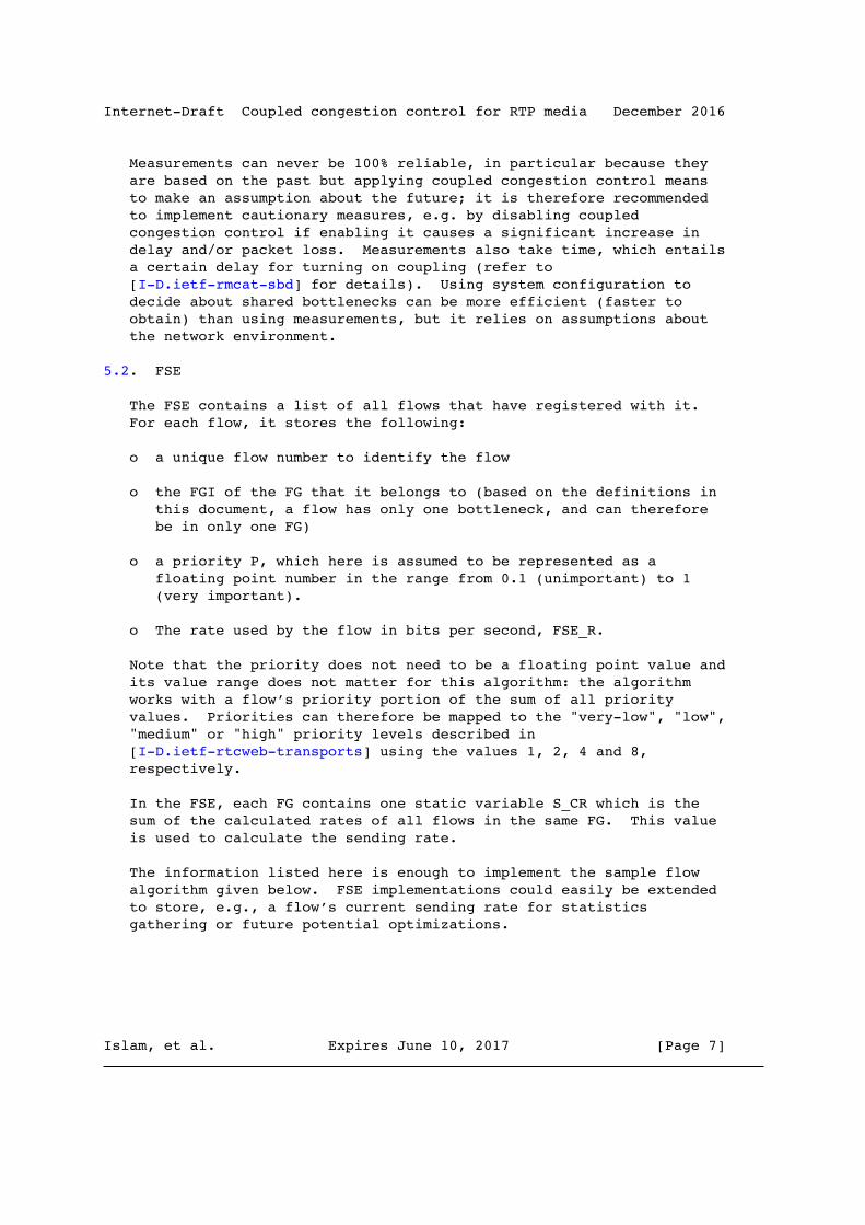
Internet-Draft Coupled congestion control for RTP media December 2016
Measurements can never be 100% reliable, in particular because they are based on the past but applying coupled congestion control means to make an assumption about the future; it is therefore recommended to implement cautionary measures, e.g. by disabling coupled congestion control if enabling it causes a significant increase in delay and/or packet loss. Measurements also take time, which entails a certain delay for turning on coupling (refer to [I-D.ietf-rmcat-sbd] for details). Using system configuration to decide about shared bottlenecks can be more efficient (faster to obtain) than using measurements, but it relies on assumptions about the network environment.
5.2. FSE
The FSE contains a list of all flows that have registered with it. For each flow, it stores the following:
o a unique flow number to identify the flow
o the FGI of the FG that it belongs to (based on the definitions in this document, a flow has only one bottleneck, and can therefore be in only one FG)
o a priority P, which here is assumed to be represented as a floating point number in the range from 0.1 (unimportant) to 1 (very important).
o The rate used by the flow in bits per second, FSE_R.
Note that the priority does not need to be a floating point value and its value range does not matter for this algorithm: the algorithm works with a flow’s priority portion of the sum of all priority values. Priorities can therefore be mapped to the "very-low", "low", "medium" or "high" priority levels described in [I-D.ietf-rtcweb-transports] using the values 1, 2, 4 and 8, respectively.
In the FSE, each FG contains one static variable S_CR which is the sum of the calculated rates of all flows in the same FG. This value is used to calculate the sending rate.
The information listed here is enough to implement the sample flow algorithm given below. FSE implementations could easily be extended to store, e.g., a flow’s current sending rate for statistics gathering or future potential optimizations.
Islam, et al. Expires June 10, 2017 [Page 7]
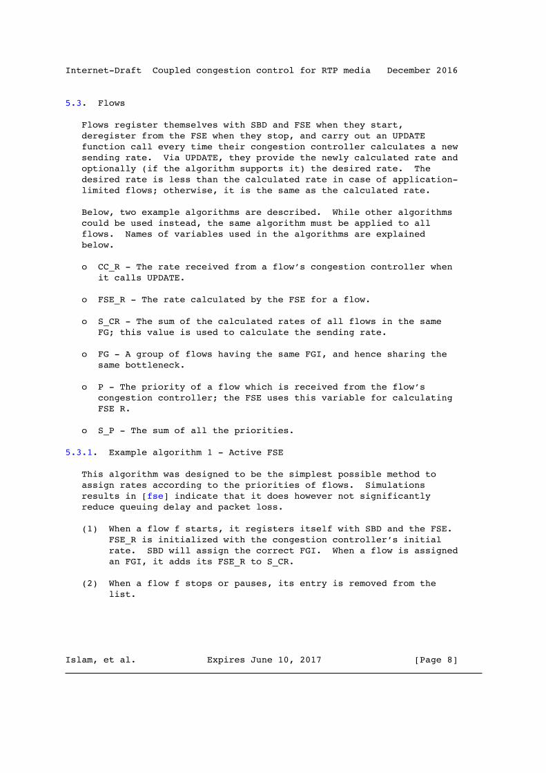
Internet-Draft Coupled congestion control for RTP media December 2016
5.3. Flows
Flows register themselves with SBD and FSE when they start, deregister from the FSE when they stop, and carry out an UPDATE function call every time their congestion controller calculates a new sending rate. Via UPDATE, they provide the newly calculated rate and optionally (if the algorithm supports it) the desired rate. The desired rate is less than the calculated rate in case of application- limited flows; otherwise, it is the same as the calculated rate.
Below, two example algorithms are described. While other algorithms could be used instead, the same algorithm must be applied to all flows. Names of variables used in the algorithms are explained below.
o CC_R - The rate received from a flow’s congestion controller when it calls UPDATE.
o FSE_R - The rate calculated by the FSE for a flow.
o S_CR - The sum of the calculated rates of all flows in the same FG; this value is used to calculate the sending rate.
o FG - A group of flows having the same FGI, and hence sharing the same bottleneck.
o P - The priority of a flow which is received from the flow’s congestion controller; the FSE uses this variable for calculating FSE R.
o S_P - The sum of all the priorities.
5.3.1. Example algorithm 1 - Active FSE
This algorithm was designed to be the simplest possible method to assign rates according to the priorities of flows. Simulations results in [fse] indicate that it does however not significantly reduce queuing delay and packet loss.
(1) When a flow f starts, it registers itself with SBD and the FSE. FSE_R is initialized with the congestion controller’s initial rate. SBD will assign the correct FGI. When a flow is assigned an FGI, it adds its FSE_R to S_CR.
(2) When a flow f stops or pauses, its entry is removed from the list.
Islam, et al. Expires June 10, 2017 [Page 8]

Internet-Draft Coupled congestion control for RTP media December 2016
(3) Every time the congestion controller of the flow f determines a new sending rate CC_R, the flow calls UPDATE, which carries out the tasks listed below to derive the new sending rates for all the flows in the FG. A flow’s UPDATE function uses a local (i.e. per-flow) temporary variable S_P, which is the sum of all the priorities.
(a) It updates S_CR.
S_CR = S_CR + CC_R - FSE_R(f)
(b) It calculates the sum of all the priorities, S_P.
S_P = 0 for all flows i in FG do S_P = S_P + P(i) end for
(c) It calculates the sending rates for all the flows in an FG and distributes them.
for all flows i in FG do FSE_R(i) = (P(i)*S_CR)/S_P send FSE_R(i) to the flow i end for
5.3.2. Example algorithm 2 - Conservative Active FSE
This algorithm extends algorithm 1 to conservatively emulate the behavior of a single flow by proportionally reducing the aggregate rate on congestion. Simulations results in [fse] indicate that it can significantly reduce queuing delay and packet loss.
(1) When a flow f starts, it registers itself with SBD and the FSE. FSE_R is initialized with the congestion controller’s initial rate. SBD will assign the correct FGI. When a flow is assigned an FGI, it adds its FSE_R to S_CR.
(2) When a flow f stops or pauses, its entry is removed from the list.
(3) Every time the congestion controller of the flow f determines a new sending rate CC_R, the flow calls UPDATE, which carries out the tasks listed below to derive the new sending rates for all the flows in the FG. A flow’s UPDATE function uses a local
Islam, et al. Expires June 10, 2017 [Page 9]

Internet-Draft Coupled congestion control for RTP media December 2016
(i.e. per-flow) temporary variable S_P, which is the sum of all the priorities, and a local variable DELTA, which is used to calculate the difference between CC_R and the previously stored FSE_R. To prevent flows from either ignoring congestion or overreacting, a timer keeps them from changing their rates immediately after the common rate reduction that follows a congestion event. This timer is set to 2 RTTs of the flow that experienced congestion because it is assumed that a congestion event can persist for up to one RTT of that flow, with another RTT added to compensate for fluctuations in the measured RTT value.
(a) It updates S_CR based on DELTA.
if Timer has expired or not set then DELTA = CC_R - FSE_R(f) if DELTA < 0 then // Reduce S_CR proportionally S_CR = S_CR * CC_R / FSE_R(f) Set Timer for 2 RTTs else S_CR = S_CR + DELTA end if end if
(b) It calculates the sum of all the priorities, S_P.
S_P = 0 for all flows i in FG do S_P = S_P + P(i) end for
(c) It calculates the sending rates for all the flows in an FG and distributes them.
for all flows i in FG do FSE_R(i) = (P(i)*S_CR)/S_P send FSE_R(i) to the flow i end for
6. Application
This section specifies how the FSE can be applied to specific congestion control mechanisms and makes general recommendations that facilitate applying the FSE to future congestion controls.
Islam, et al. Expires June 10, 2017 [Page 10]
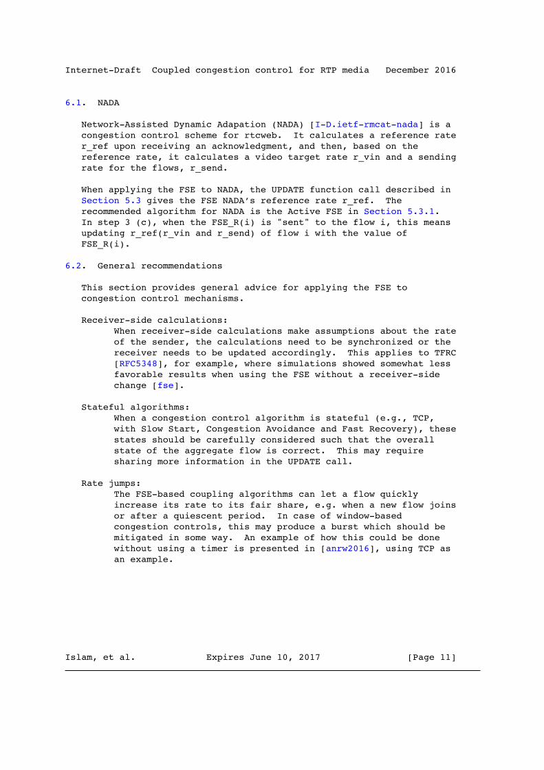
Internet-Draft Coupled congestion control for RTP media December 2016
6.1. NADA
Network-Assisted Dynamic Adapation (NADA) [I-D.ietf-rmcat-nada] is a congestion control scheme for rtcweb. It calculates a reference rate r_ref upon receiving an acknowledgment, and then, based on the reference rate, it calculates a video target rate r_vin and a sending rate for the flows, r_send.
When applying the FSE to NADA, the UPDATE function call described in Section 5.3 gives the FSE NADA’s reference rate r_ref. The recommended algorithm for NADA is the Active FSE in Section 5.3.1. In step 3 (c), when the FSE_R(i) is "sent" to the flow i, this means updating r_ref(r_vin and r_send) of flow i with the value of FSE_R(i).
6.2. General recommendations
This section provides general advice for applying the FSE to congestion control mechanisms.
Receiver-side calculations: When receiver-side calculations make assumptions about the rate of the sender, the calculations need to be synchronized or the receiver needs to be updated accordingly. This applies to TFRC [RFC5348], for example, where simulations showed somewhat less favorable results when using the FSE without a receiver-side change [fse].
Stateful algorithms: When a congestion control algorithm is stateful (e.g., TCP, with Slow Start, Congestion Avoidance and Fast Recovery), these states should be carefully considered such that the overall state of the aggregate flow is correct. This may require sharing more information in the UPDATE call.
Rate jumps: The FSE-based coupling algorithms can let a flow quickly increase its rate to its fair share, e.g. when a new flow joins or after a quiescent period. In case of window-based congestion controls, this may produce a burst which should be mitigated in some way. An example of how this could be done without using a timer is presented in [anrw2016], using TCP as an example.
Islam, et al. Expires June 10, 2017 [Page 11]

Internet-Draft Coupled congestion control for RTP media December 2016
7. Expected feedback from experiments
The algorithm described in this memo has so far been evaluated using simulations covering all the tests for more than one flow from [I-D.ietf-rmcat-eval-test] (see [IETF-93], [IETF-94]). Experiments should confirm these results using at least the NADA congestion control algorithm with real-life code (e.g., browsers communicating over an emulated network covering the conditions in [I-D.ietf-rmcat-eval-test]. The tests with real-life code should be repeated afterwards in real network environments and monitored. Experiments should investigate cases where the media coder’s output rate is below the rate that is calculated by the coupling algorithm (FSE_R in algorithms 1 and 2, section 5.3). Implementers and testers are invited to document their findings in an Internet draft.
8. Acknowledgements
This document has benefitted from discussions with and feedback from Andreas Petlund, Anna Brunstrom, David Hayes, David Ros (who also gave the FSE its name), Ingemar Johansson, Karen Nielsen, Kristian Hiorth, Mirja Kuehlewind, Martin Stiemerling, Varun Singh, Xiaoqing Zhu, and Zaheduzzaman Sarker. The authors would like to especially thank Xiaoqing Zhu and Stefan Holmer for helping with NADA and GCC.
This work was partially funded by the European Community under its Seventh Framework Programme through the Reducing Internet Transport Latency (RITE) project (ICT-317700).
9. IANA Considerations
This memo includes no request to IANA.
10. Security Considerations
In scenarios where the architecture described in this document is applied across applications, various cheating possibilities arise: e.g., supporting wrong values for the calculated rate, the desired rate, or the priority of a flow. In the worst case, such cheating could either prevent other flows from sending or make them send at a rate that is unreasonably large. The end result would be unfair behavior at the network bottleneck, akin to what could be achieved with any UDP based application. Hence, since this is no worse than UDP in general, there seems to be no significant harm in using this in the absence of UDP rate limiters.
Islam, et al. Expires June 10, 2017 [Page 12]

Internet-Draft Coupled congestion control for RTP media December 2016
In the case of a single-user system, it should also be in the interest of any application programmer to give the user the best possible experience by using reasonable flow priorities or even letting the user choose them. In a multi-user system, this interest may not be given, and one could imagine the worst case of an "arms race" situation, where applications end up setting their priorities to the maximum value. If all applications do this, the end result is a fair allocation in which the priority mechanism is implicitly eliminated, and no major harm is done.
11. References
11.1. Normative References
[I-D.ietf-rmcat-nada] Zhu, X., Pan, R., Ramalho, M., Cruz, S., Jones, P., Fu, J., D’Aronco, S., and C. Ganzhorn, "NADA: A Unified Congestion Control Scheme for Real-Time Media", draft-ietf-rmcat-nada-03 (work in progress), September 2016.
[RFC2119] Bradner, S., "Key words for use in RFCs to Indicate Requirement Levels", BCP 14, RFC 2119, DOI 10.17487/ RFC2119, March 1997, <http://www.rfc-editor.org/info/rfc2119>.
[RFC3124] Balakrishnan, H. and S. Seshan, "The Congestion Manager", RFC 3124, DOI 10.17487/RFC3124, June 2001, <http://www.rfc-editor.org/info/rfc3124>.
[RFC5348] Floyd, S., Handley, M., Padhye, J., and J. Widmer, "TCP Friendly Rate Control (TFRC): Protocol Specification", RFC 5348, DOI 10.17487/RFC5348, September 2008, <http://www.rfc-editor.org/info/rfc5348>.
11.2. Informative References
[I-D.ietf-rmcat-eval-test] Sarker, Z., Singh, V., Zhu, X., and M. Ramalho, "Test Cases for Evaluating RMCAT Proposals", draft-ietf-rmcat-eval-test-04 (work in progress), October 2016.
[I-D.ietf-rmcat-gcc] Holmer, S., Lundin, H., Carlucci, G., Cicco, L., and S. Mascolo, "A Google Congestion Control Algorithm for Real- Time Communication", draft-ietf-rmcat-gcc-02 (work in
Islam, et al. Expires June 10, 2017 [Page 13]

Internet-Draft Coupled congestion control for RTP media December 2016
progress), July 2016.
[I-D.ietf-rmcat-sbd] Hayes, D., Ferlin, S., Welzl, M., and K. Hiorth, "Shared Bottleneck Detection for Coupled Congestion Control for RTP Media.", draft-ietf-rmcat-sbd-04 (work in progress), March 2016.
[I-D.ietf-rtcweb-transports] Alvestrand, H., "Transports for WebRTC", draft-ietf-rtcweb-transports-11.txt (work in progress), January 2016.
[IETF-93] Islam, S., Welzl, M., and S. Gjessing, "Updates on Coupled Congestion Control for RTP Media", July 2015, <https://www.ietf.org/proceedings/93/rmcat.html>.
[IETF-94] Islam, S., Welzl, M., and S. Gjessing, "Updates on Coupled Congestion Control for RTP Media", November 2015, <https://www.ietf.org/proceedings/94/rmcat.html>.
[RFC7478] Holmberg, C., Hakansson, S., and G. Eriksson, "Web Real- Time Communication Use Cases and Requirements", RFC 7478, DOI 10.17487/RFC7478, March 2015, <http://www.rfc-editor.org/info/rfc7478>.
[anrw2016] Islam, S. and M. Welzl, "Start Me Up:Determining and Sharing TCP’s Initial Congestion Window", ACM, IRTF, ISOC Applied Networking Research Workshop 2016 (ANRW 2016) , 2016.
[fse] Islam, S., Welzl, M., Gjessing, S., and N. Khademi, "Coupled Congestion Control for RTP Media", ACM SIGCOMM Capacity Sharing Workshop (CSWS 2014) and ACM SIGCOMM CCR 44(4) 2014; extended version available as a technical report from http://safiquli.at.ifi.uio.no/paper/fse-tech-report.pdf , 2014.
[fse-noms] Islam, S., Welzl, M., Hayes, D., and S. Gjessing, "Managing Real-Time Media Flows through a Flow State Exchange", IEEE NOMS 2016, Istanbul, Turkey , 2016.
[rtcweb-rtp-usage] Perkins, C., Westerlund, M., and J. Ott, "Web Real-Time Communication (WebRTC): Media Transport and Use of RTP",
Islam, et al. Expires June 10, 2017 [Page 14]
Internet-Draft Coupled congestion control for RTP media December 2016
draft-ietf-rtcweb-rtp-usage-26.txt (work in progress), March 2016.
[transport-multiplex] Westerlund, M. and C. Perkins, "Multiple RTP Sessions on a Single Lower-Layer Transport", draft-westerlund-avtcore-transport-multiplexing-07.txt (work in progress), October 2013.
Appendix A. Application to GCC
Google Congestion Control (GCC) [I-D.ietf-rmcat-gcc] is another congestion control scheme for RTP flows that is under development. GCC is not yet finalised, but at the time of this writing, the rate control of GCC employs two parts: controlling the bandwidth estimate based on delay, and controlling the bandwidth estimate based on loss. Both are designed to estimate the available bandwidth, A_hat.
When applying the FSE to GCC, the UPDATE function call described in Section 5.3 gives the FSE GCC’s estimate of available bandwidth A_hat. The recommended algorithm for GCC is the Active FSE in Section 5.3.1. In step 3 (c), when the FSE_R(i) is "sent" to the flow i, this means updating A_hat of flow i with the value of FSE_R(i).
Appendix B. Scheduling
When connections originate from the same host, it would be possible to use only one single sender-side congestion controller which determines the overall allowed sending rate, and then use a local scheduler to assign a proportion of this rate to each RTP session. This way, priorities could also be implemented as a function of the scheduler. The Congestion Manager (CM) [RFC3124] also uses such a scheduling function.
Appendix C. Example algorithm - Passive FSE
Active algorithms calculate the rates for all the flows in the FG and actively distribute them. In a passive algorithm, UPDATE returns a rate that should be used instead of the rate that the congestion controller has determined. This can make a passive algorithm easier to implement; however, when round-trip times of flows are unequal, shorter-RTT flows may (depending on the congestion control algorithm) update and react to the overall FSE state more often than longer-RTT flows, which can produce unwanted side effects. This problem is more
Islam, et al. Expires June 10, 2017 [Page 15]

Internet-Draft Coupled congestion control for RTP media December 2016
significant when the congestion control convergence depends on the RTT. While the passive algorithm works better for congestion controls with RTT-independent convergence, it can still produce oscillations on short time scales. The algorithm described below is therefore considered as highly experimental. Results of a simplified passive FSE algorithm with both NADA and GCC can be found in [fse-noms].
This passive version of the FSE stores the following information in addition to the variables described in Section 5.2:
o The desired rate DR. This can be smaller than the calculated rate if the application feeding into the flow has less data to send than the congestion controller would allow. In case of a bulk transfer, DR must be set to CC_R received from the flow’s congestion module.
The passive version of the FSE contains one static variable per FG called TLO (Total Leftover Rate -- used to let a flow ’take’ bandwidth from application-limited or terminated flows) which is initialized to 0. For the passive version, S_CR is limited to increase or decrease as conservatively as a flow’s congestion controller decides in order to prohibit sudden rate jumps.
(1) When a flow f starts, it registers itself with SBD and the FSE. FSE_R and DR are initialized with the congestion controller’s initial rate. SBD will assign the correct FGI. When a flow is assigned an FGI, it adds its FSE_R to S_CR.
(2) When a flow f stops or pauses, it sets its DR to 0 and sets P to -1.
(3) Every time the congestion controller of the flow f determines a new sending rate CC_R, assuming the flow’s new desired rate new_DR to be "infinity" in case of a bulk data transfer with an unknown maximum rate, the flow calls UPDATE, which carries out the tasks listed below to derive the flow’s new sending rate, Rate. A flow’s UPDATE function uses a few local (i.e. per-flow) temporary variables, which are all initialized to 0: DELTA, new_S_CR and S_P.
(a) For all the flows in its FG (including itself), it calculates the sum of all the calculated rates, new_S_CR. Then it calculates the difference between FSE_R(f) and CC_R, DELTA.
Islam, et al. Expires June 10, 2017 [Page 16]

Internet-Draft Coupled congestion control for RTP media December 2016
for all flows i in FG do new_S_CR = new_S_CR + FSE_R(i) end for DELTA = CC_R - FSE_R(f)
(b) It updates S_CR, FSE_R(f) and DR(f).
FSE_R(f) = CC_R if DELTA > 0 then // the flow’s rate has increased S_CR = S_CR + DELTA else if DELTA < 0 then S_CR = new_S_CR + DELTA end if DR(f) = min(new_DR,FSE_R(f))
(c) It calculates the leftover rate TLO, removes the terminated flows from the FSE and calculates the sum of all the priorities, S_P.
for all flows i in FG do if P(i)<0 then delete flow else S_P = S_P + P(i) end if end for if DR(f) < FSE_R(f) then TLO = TLO + (P(f)/S_P) * S_CR - DR(f)) end if
(d) It calculates the sending rate, Rate.
Rate = min(new_DR, (P(f)*S_CR)/S_P + TLO)
if Rate != new_DR and TLO > 0 then TLO = 0 // f has ’taken’ TLO end if
(e) It updates DR(f) and FSE_R(f) with Rate.
if Rate > DR(f) then DR(f) = Rate end if FSE_R(f) = Rate
Islam, et al. Expires June 10, 2017 [Page 17]

Internet-Draft Coupled congestion control for RTP media December 2016
The goals of the flow algorithm are to achieve prioritization, improve network utilization in the face of application-limited flows, and impose limits on the increase behavior such that the negative impact of multiple flows trying to increase their rate together is minimized. It does that by assigning a flow a sending rate that may not be what the flow’s congestion controller expected. It therefore builds on the assumption that no significant inefficiencies arise from temporary application-limited behavior or from quickly jumping to a rate that is higher than the congestion controller intended. How problematic these issues really are depends on the controllers in use and requires careful per-controller experimentation. The coupled congestion control mechanism described here also does not require all controllers to be equal; effects of heterogeneous controllers, or homogeneous controllers being in different states, are also subject to experimentation.
This algorithm gives all the leftover rate of application-limited flows to the first flow that updates its sending rate, provided that this flow needs it all (otherwise, its own leftover rate can be taken by the next flow that updates its rate). Other policies could be applied, e.g. to divide the leftover rate of a flow equally among all other flows in the FGI.
C.1. Example operation (passive)
In order to illustrate the operation of the passive coupled congestion control algorithm, this section presents a toy example of two flows that use it. Let us assume that both flows traverse a common 10 Mbit/s bottleneck and use a simplistic congestion controller that starts out with 1 Mbit/s, increases its rate by 1 Mbit/s in the absence of congestion and decreases it by 2 Mbit/s in the presence of congestion. For simplicity, flows are assumed to always operate in a round-robin fashion. Rate numbers below without units are assumed to be in Mbit/s. For illustration purposes, the actual sending rate is also shown for every flow in FSE diagrams even though it is not really stored in the FSE.
Flow #1 begins. It is a bulk data transfer and considers itself to have top priority. This is the FSE after the flow algorithm’s step 1:
---------------------------------------- | # | FGI | P | FSE_R | DR | Rate | | | | | | | | | 1 | 1 | 1 | 1 | 1 | 1 | ---------------------------------------- S_CR = 1, TLO = 0
Islam, et al. Expires June 10, 2017 [Page 18]

Internet-Draft Coupled congestion control for RTP media December 2016
Its congestion controller gradually increases its rate. Eventually, at some point, the FSE should look like this:
----------------------------------------- | # | FGI | P | FSE_R | DR | Rate | | | | | | | | | 1 | 1 | 1 | 10 | 10 | 10 | ----------------------------------------- S_CR = 10, TLO = 0
Now another flow joins. It is also a bulk data transfer, and has a lower priority (0.5):
------------------------------------------ | # | FGI | P | FSE_R | DR | Rate | | | | | | | | | 1 | 1 | 1 | 10 | 10 | 10 | | 2 | 1 | 0.5 | 1 | 1 | 1 | ------------------------------------------ S_CR = 11, TLO = 0
Now assume that the first flow updates its rate to 8, because the total sending rate of 11 exceeds the total capacity. Let us take a closer look at what happens in step 3 of the flow algorithm.
CC_R = 8. new_DR = infinity. 3 a) new_S_CR = 11; DELTA = 8 - 10 = -2. 3 b) FSE_Rf) = 8. DELTA is negative, hence S_CR = 9; DR(f) = 8. 3 c) S_P = 1.5. 3 d) new sending rate = min(infinity, 1/1.5 * 9 + 0) = 6. 3 e) FSE_R(f) = 6.
The resulting FSE looks as follows: ------------------------------------------- | # | FGI | P | FSE_R | DR | Rate | | | | | | | | | 1 | 1 | 1 | 6 | 8 | 6 | | 2 | 1 | 0.5 | 1 | 1 | 1 | ------------------------------------------- S_CR = 9, TLO = 0
Islam, et al. Expires June 10, 2017 [Page 19]

Internet-Draft Coupled congestion control for RTP media December 2016
The effect is that flow #1 is sending with 6 Mbit/s instead of the 8 Mbit/s that the congestion controller derived. Let us now assume that flow #2 updates its rate. Its congestion controller detects that the network is not fully saturated (the actual total sending rate is 6+1=7) and increases its rate.
CC_R=2. new_DR = infinity. 3 a) new_S_CR = 7; DELTA = 2 - 1 = 1. 3 b) FSE_R(f) = 2. DELTA is positive, hence S_CR = 9 + 1 = 10; DR(f) = 2. 3 c) S_P = 1.5. 3 d) new sending rate = min(infinity, 0.5/1.5 * 10 + 0) = 3.33. 3 e) DR(f) = FSE_R(f) = 3.33.
The resulting FSE looks as follows: ------------------------------------------- | # | FGI | P | FSE_R | DR | Rate | | | | | | | | | 1 | 1 | 1 | 6 | 8 | 6 | | 2 | 1 | 0.5 | 3.33 | 3.33 | 3.33 | ------------------------------------------- S_CR = 10, TLO = 0
The effect is that flow #2 is now sending with 3.33 Mbit/s, which is close to half of the rate of flow #1 and leads to a total utilization of 6(#1) + 3.33(#2) = 9.33 Mbit/s. Flow #2’s congestion controller has increased its rate faster than the controller actually expected. Now, flow #1 updates its rate. Its congestion controller detects that the network is not fully saturated and increases its rate. Additionally, the application feeding into flow #1 limits the flow’s sending rate to at most 2 Mbit/s.
Islam, et al. Expires June 10, 2017 [Page 20]

Internet-Draft Coupled congestion control for RTP media December 2016
CC_R=7. new_DR=2. 3 a) new_S_CR = 9.33; DELTA = 1. 3 b) FSE_R(f) = 7, DELTA is positive, hence S_CR = 10 + 1 = 11; DR = min(2, 7) = 2. 3 c) S_P = 1.5; DR(f) < FSE_R(f), hence TLO = 1/1.5 * 11 - 2 = 5.33. 3 d) new sending rate = min(2, 1/1.5 * 11 + 5.33) = 2. 3 e) FSE_R(f) = 2.
The resulting FSE looks as follows: ------------------------------------------- | # | FGI | P | FSE_R | DR | Rate | | | | | | | | | 1 | 1 | 1 | 2 | 2 | 2 | | 2 | 1 | 0.5 | 3.33 | 3.33 | 3.33 | ------------------------------------------- S_CR = 11, TLO = 5.33
Now, the total rate of the two flows is 2 + 3.33 = 5.33 Mbit/s, i.e. the network is significantly underutilized due to the limitation of flow #1. Flow #2 updates its rate. Its congestion controller detects that the network is not fully saturated and increases its rate.
CC_R=4.33. new_DR = infinity. 3 a) new_S_CR = 5.33; DELTA = 1. 3 b) FSE_R(f) = 4.33. DELTA is positive, hence S_CR = 12; DR(f) = 4.33. 3 c) S_P = 1.5. 3 d) new sending rate: min(infinity, 0.5/1.5 * 12 + 5.33 ) = 9.33. 3 e) FSE_R(f) = 9.33, DR(f) = 9.33.
The resulting FSE looks as follows: ------------------------------------------- | # | FGI | P | FSE_R | DR | Rate | | | | | | | | | 1 | 1 | 1 | 2 | 2 | 2 | | 2 | 1 | 0.5 | 9.33 | 9.33 | 9.33 | ------------------------------------------- S_CR = 12, TLO = 0
Now, the total rate of the two flows is 2 + 9.33 = 11.33 Mbit/s. Finally, flow #1 terminates. It sets P to -1 and DR to 0. Let us
Islam, et al. Expires June 10, 2017 [Page 21]

Internet-Draft Coupled congestion control for RTP media December 2016
assume that it terminated late enough for flow #2 to still experience the network in a congested state, i.e. flow #2 decreases its rate in the next iteration.
CC_R = 7.33. new_DR = infinity. 3 a) new_S_CR = 11.33; DELTA = -2. 3 b) FSE_R(f) = 7.33. DELTA is negative, hence S_CR = 9.33; DR(f) = 7.33. 3 c) Flow 1 has P = -1, hence it is deleted from the FSE. S_P = 0.5. 3 d) new sending rate: min(infinity, 0.5/0.5*9.33 + 0) = 9.33. 3 e) FSE_R(f) = DR(f) = 9.33.
The resulting FSE looks as follows: ------------------------------------------- | # | FGI | P | FSE_R | DR | Rate | | | | | | | | | 2 | 1 | 0.5 | 9.33 | 9.33 | 9.33 | ------------------------------------------- S_CR = 9.33, TLO = 0
Appendix D. Change log
D.1. draft-welzl-rmcat-coupled-cc
D.1.1. Changes from -00 to -01
o Added change log.
o Updated the example algorithm and its operation.
D.1.2. Changes from -01 to -02
o Included an active version of the algorithm which is simpler.
o Replaced "greedy flow" with "bulk data transfer" and "non-greedy" with "application-limited".
o Updated new_CR to CC_R, and CR to FSE_R for better understanding.
Islam, et al. Expires June 10, 2017 [Page 22]

Internet-Draft Coupled congestion control for RTP media December 2016
D.1.3. Changes from -02 to -03
o Included an active conservative version of the algorithm which reduces queue growth and packet loss; added a reference to a technical report that shows these benefits with simulations.
o Moved the passive variant of the algorithm to appendix.
D.1.4. Changes from -03 to -04
o Extended SBD section.
o Added a note about window-based controllers.
D.1.5. Changes from -04 to -05
o Added a section about applying the FSE to specific congestion control algorithms, with a subsection specifying its use with NADA.
D.2. draft-ietf-rmcat-coupled-cc
D.2.1. Changes from draft-welzl-rmcat-coupled-cc-05
o Moved scheduling section to the appendix.
D.2.2. Changes from -00 to -01
o Included how to apply the algorithm to GCC.
o Updated variable names of NADA to be in line with the latest version.
o Added a reference to [I-D.ietf-rtcweb-transports] to make a connection to the prioritization text there.
D.2.3. Changes from -01 to -02
o Minor changes.
o Moved references of NADA and GCC from informative to normative.
o Added a reference for the passive variant of the algorithm.
Islam, et al. Expires June 10, 2017 [Page 23]

Internet-Draft Coupled congestion control for RTP media December 2016
D.2.4. Changes from -02 to -03
o Minor changes.
o Added a section about expected feedback from experiments.
D.2.5. Changes from -03 to -04
o Described the names of variables used in the algorithms.
o Added a diagram to illustrate the interaction between flows and the FSE.
o Added text on the trade-off of using the configuration based approach.
o Minor changes to enhance the readability.
D.2.6. Changes from -04 to -05
o Changed several occurrences of "NADA and GCC" to "NADA", including the abstract.
o Moved the application to GCC to an appendix, and made the GCC reference informative.
o Provided a few more general recommendations on applying the coupling algorithm.
Authors’ Addresses
Safiqul Islam University of Oslo PO Box 1080 Blindern Oslo, N-0316 Norway
Phone: +47 22 84 08 37 Email: [email protected]
Islam, et al. Expires June 10, 2017 [Page 24]

Internet-Draft Coupled congestion control for RTP media December 2016
Michael Welzl University of Oslo PO Box 1080 Blindern Oslo, N-0316 Norway
Phone: +47 22 85 24 20 Email: [email protected]
Stein Gjessing University of Oslo PO Box 1080 Blindern Oslo, N-0316 Norway
Phone: +47 22 85 24 44 Email: [email protected]
Islam, et al. Expires June 10, 2017 [Page 25]

Coupled Congestion Control for RTP Media
168

Chapter 11
TCP-CCC: Single-Path TCPCongestion Control Coupling
169


Internet Congestion Control Research Group M. WelzlInternet-Draft S. IslamIntended status: Experimental K. HiorthExpires: May 4, 2017 University of Oslo J. You Huawei October 31, 2016
TCP-CCC: single-path TCP congestion control coupling draft-welzl-tcp-ccc-00
Abstract
This document specifies a method, TCP-CCC, to combine the congestion controls of multiple TCP connections between the same pair of hosts. This can have several performance benefits, and it makes it possible to precisely assign a share of the congestion window to the connections based on priorities. This document also addresses the problem that TCP connections between the same pair of hosts may not share the same path. We discuss methods to detect if, or enforce that connections traverse a common bottleneck.
Requirements Language
The key words "MUST", "MUST NOT", "REQUIRED", "SHALL", "SHALL NOT", "SHOULD", "SHOULD NOT", "RECOMMENDED", "MAY", and "OPTIONAL" in this document are to be interpreted as described in [RFC2119].
Status of This Memo
This Internet-Draft is submitted in full conformance with the provisions of BCP 78 and BCP 79.
Internet-Drafts are working documents of the Internet Engineering Task Force (IETF). Note that other groups may also distribute working documents as Internet-Drafts. The list of current Internet- Drafts is at http://datatracker.ietf.org/drafts/current/.
Internet-Drafts are draft documents valid for a maximum of six months and may be updated, replaced, or obsoleted by other documents at any time. It is inappropriate to use Internet-Drafts as reference material or to cite them other than as "work in progress."
This Internet-Draft will expire on May 4, 2017.
Welzl, et al. Expires May 4, 2017 [Page 1]

Internet-Draft TCP-CCC October 2016
Copyright Notice
Copyright (c) 2016 IETF Trust and the persons identified as the document authors. All rights reserved.
This document is subject to BCP 78 and the IETF Trust’s Legal Provisions Relating to IETF Documents (http://trustee.ietf.org/license-info) in effect on the date of publication of this document. Please review these documents carefully, as they describe your rights and restrictions with respect to this document. Code Components extracted from this document must include Simplified BSD License text as described in Section 4.e of the Trust Legal Provisions and are provided without warranty as described in the Simplified BSD License.
Table of Contents
1. Introduction . . . . . . . . . . . . . . . . . . . . . . . . 2 2. Coupled Congestion Control . . . . . . . . . . . . . . . . . 3 3. Ensuring a Common Bottleneck . . . . . . . . . . . . . . . . 6 3.1. Encapsulation . . . . . . . . . . . . . . . . . . . . . . 7 3.1.1. TCP in UDP . . . . . . . . . . . . . . . . . . . . . 7 3.1.2. Other Methods . . . . . . . . . . . . . . . . . . . . 14 4. Related Work . . . . . . . . . . . . . . . . . . . . . . . . 14 5. Implementation Status . . . . . . . . . . . . . . . . . . . . 15 6. IANA Considerations . . . . . . . . . . . . . . . . . . . . . 15 7. Security Considerations . . . . . . . . . . . . . . . . . . . 15 8. Acknowledgements . . . . . . . . . . . . . . . . . . . . . . 16 9. References . . . . . . . . . . . . . . . . . . . . . . . . . 16 9.1. Normative References . . . . . . . . . . . . . . . . . . 16 9.2. Informative References . . . . . . . . . . . . . . . . . 16 Authors’ Addresses . . . . . . . . . . . . . . . . . . . . . . . 19
1. Introduction
When multiple TCP connections between the same host pair compete on the same bottleneck, they often incur more delay and losses than a single TCP connection. Moreover, it is often not possible to precisely divide the available capacity among the connections. To address this problem, this document presents TCP-CCC, a method to combine the congestion controls of multiple TCP connections between the same pair of hosts. This can have several performance benefits:
o Reduced average loss and queuing delay (because the competition between the encapsulated TCP connections is avoided)
o Assign a precise capacity share based on a priority.
Welzl, et al. Expires May 4, 2017 [Page 2]

Internet-Draft TCP-CCC October 2016
o Even in the absence of prioritization, better fairness between the TCP connections.
o No need for new connections to slow start up to a reasonable cwnd value that ongoing connections already have: a connection can immediately be assigned its share of the aggregate’s total cwnd. This can significantly reduce the completion time of short connections.
All of these benefits only play out when there are more than one TCP connections. Some of the benefits in the list above are more significant when some transfers are short. This makes the usage of TCP-CCC especially attractive in situations where some transfers are short.
We discuss methods to determine if connections traverse the same bottleneck as well as methods to ensure this. To this end, we propose a light-weight, dynamically configured TCP-in-UDP (TiU) encapsulation scheme. TiU is optional, as our coupled congestion control strategy is applicable wherever overlapping TCP flows must follow the same path (such as when routed over a VPN tunnel).
2. Coupled Congestion Control
For each TCP connection c, the algorithm described below receives cwnd and ssthresh as input and stores the following information:
o the Connection ID.
o a priority P(c) -- e.g., an integer value in the range from 1 (unimportant) to 10 (very important).
o The previously used cwnd used by the connection c, ccc_cwnd(c).
o The previously used ssthresh used by the connection c, ccc_ssthresh(c).
Three global variables sum_cwnd, sum_ssthresh and sum_p are used to represent the sum of all the ccc_cwnd values, ccc_sshtresh values and priorities of all TCP connections, respectively. sum_cwnd and sum_ssthresh are used to update the cwnd and ssthresh values for all connections.
This algorithm emulates the behavior of a single TCP connection by choosing one connection as the connection that dictates the increase / decrease behavior for the aggregate. We call it the "Coordinating Connection" (CoCo). The algorithm was designed to be as simple as possible. Below, abbreviations are used to refer to the phases of
Welzl, et al. Expires May 4, 2017 [Page 3]

Internet-Draft TCP-CCC October 2016
TCP congestion control as defined in [RFC5681]: SS refers to Slow Start, CA refers to Congestion Avoidance and FR refers to Fast Recovery.
For simplicity, this algorithm refrains from changing cwnd when a connection is in FR. SS should not happen as long as ACKs arrive. Hence, the algorithm ensures that the aggregate’s behavior is only dictated by SS when all connections are in the SS phase. We use a bit array, ssbits, with a bit for each connection in the group. We set the bit if the connection state is SS due to an RTO.
(1) When a connection c starts, it adds its priority P(c) to sum_p. If it is the very first connection, it sets sum_cwnd to its own cwnd. After that, the connection’s globally known cwnd and ssthresh values (ccc_cwnd(c) and ccc_ssthresh(c)) are updated, and the connection updates its own cwnd and ssthresh values to be equal to ccc_cwnd(c) and ccc_ssthresh(c).
ccc_P(c) = P sum_P = sum_P + P sum_cwnd sum_cwnd + cwnd ccc_cwnd(c) P = sum_cwnd / sum_P ccc_ssthresh(c) = ssthresh if sum_ssthresh > 0 then ccc_ssthresh(c) P = sum_ssthresh / sum_P end if // Update c’s own cwnd and ssthresh for immediate use: Send ccc_cwnd(c) and ccc_ssthresh(c) to c
(2) When a connection c stops, its entry is removed. sum_p is recalculated.
if c = CoCo then Coco = the next connection end if sum_p sum_p - ccc_P(c) Remove ccc_P(c), ccc_cwnd(c), ccc_ssthresh(c)
(3) Every time the congestion controller of a connection c calculates a new cwnd, the connection calls UPDATE, which carries out the tasks listed below to derive the new cwnd and ssthresh values. Whenever the CoCo calls UPDATE, sum_cwnd and sum_ssthresh are additionally updated to reflect the current sum of all stored ccc_cwnd and ccc_ssthresh values. Initially,
Welzl, et al. Expires May 4, 2017 [Page 4]

Internet-Draft TCP-CCC October 2016
there is only one connection and this connection automatically becomes the CoCo. It updates sum_cwnd to its own cwnd and sets sum_ssthresh to 0.
(4) WHEN a non-CoCo connection c CALLS UPDATE......
if(all of the connections including CoCo are in CA but c is in FR) c becomes the new CoCo. else if(c is in CA or SS) c’s cwnd is assigned its previously stored ccc_cwnd value.
(5) WHEN c(CoCo) CALLS UPDATE......
if CoCo == c then if state == CA and ssbits(c) == 0 then if cwnd >= ccc_cwnd(c) then // increased cwnd sum_cwnd = sum_cwnd + cwnd - ccc_cwnd(c) else sum_cwnd = sum_cwnd * cwnd / ccc_cwnd(c) end if ccc_cwnd(c) = ccc_P(c) * sum_cwnd / sum_p ccc_ssthresh(c) ssthresh if sum_ssthresh > 0 then ccc_ssthresh(c) ccc_P(c) * sum_ssthresh/sum_p end if else if state == FR then sum_ssthresh = sum_cwnd/2 else if state == SS then if c experienced a timeout then ssbits(c) = 1 end if if ssbits(x) == 1 for all x then ssbits(x) = 0 // for all x sum_cwnd = sum_cwnd * cwnd / ccc_cwnd(c) ccc_cwnd(c) = ccc_P(c) * sum_cwnd / sum_p sum_ssthresh = sum_cwnd/2 else CoCo = first connection where ccc_state == SS end if end if end if
(6) After that, if the ccc_state(c) is not equal to FR
Welzl, et al. Expires May 4, 2017 [Page 5]

Internet-Draft TCP-CCC October 2016
if state != FR then Send ccc_cwnd(c) and ccc_ssthresh(c) to c end if
When a flow gets a large share of the aggregate immediately after joining, it can potentially create a burst in the network. We propose a mechanism [anrw2016] to clock the packet transmission out by using the ack-clock of TCP. Our algorithm achieves a form of "pacing", but it does not rely on any timers.
When a connection c joins, it turns on the ack-clock feature and calculates the share of the aggregate, clocked_cwnd c. Below, we illustrate the ack-clock mechanism that is used to distribute the share of the cwnd based on the acknowledgements received from other flows.
if clocked_cwnd(c) <= 0 then return // alg. ends; other connections can increase cwnd again end if if number_of_acks c % N = 0 then send a new segment for connection c clocked_cwnd(c)= clocked_cwnd(c) - 1 end if number_of_acks(c) = number_of_acks(c) + 1
3. Ensuring a Common Bottleneck
Our algorithm, as well as EFCM [EFCM], E-TCP [EFCM] and the CM [RFC3124] assume that multiple TCP connections between the same host pair traverse the same bottleneck. This is not always true: load- balancing mechanisms such as Link Aggregation Group (LAG) and Equal- Cost Multi-Path (ECMP) may force them to take different paths [RFC7424]. If this leads to the connections seeing different bottlenecks, combining the congestion controllers would incur wrong behavior. There are, however, several application scenarios where the single-bottleneck assumption is correct.
Sometimes, the network configuration is known, and it is known that mechanisms such as ECMP and LAG do not operate on the bottleneck or are simply not in use. Alternatively, measurements can infer whether flows traverse the same bottleneck [I-D.ietf-rmcat-sbd]. When IPv6 is available, the TCP connections could be assigned the same IPv6 flow label. According to [RFC6437], "The usage of the 3-tuple of the Flow Label, Source Address, and Destination Address fields enables efficient IPv6 flow classification, where only IPv6 main header
Welzl, et al. Expires May 4, 2017 [Page 6]
Internet-Draft TCP-CCC October 2016
fields in fixed positions are used" - this would be favorable for TCP congestion control coupling. However, this [RFC6437] does not make a clear recommendation about either using the 3-tuple or 5-tuple (which includes the port numbers) - both methods are valid. Thus, whether it works to use the flow label as the sole means to put connections on the same path depends on router configuration. When it works, it is an attractive option because it does not require changing the receiver.
Finally, encapsulating packets with a header that ensures a common path is another possibility to make connections traverse the same bottleneck. We will discuss encapsulation in the next section.
3.1. Encapsulation
3.1.1. TCP in UDP
3.1.1.1. Introduction
We want to be able to ensure that TCP congestion control coupling can always work, provided that the required code is available at the receiver - and be able to efficiently fall back to the standard behaviour in case it is not. To achieve this, we present a method, TCP-in-UDP (TiU), to encapsulate multiple TCP connections using the same UDP port pair.
TCP-in-UDP (TiU) is based on [Che13]. It differs from it in that:
o Other than [Che13], TiU encapsulates multiple TCP connections using the same UDP port number pair. TCP port numbers are preserved; a single well-known UDP port is used for TiU. If TiU is implemented in the kernel, this allows using normal TCP sockets, where enabling the usage of TiU could be done via a socket option, for example.
o The header format is slightly different to allow representing a TCP connection with a few bits that are encoded across the original TCP header’s "Reserved" field and the URG (Urgent) flag to encode a Connection ID. With this encoding, similar to the encapsulation in [Che13], the total TiU header size does not exceed the original TCP header size.
o A (TiU-encapsulated) TCP SYN uses a newly defined TCP option to establish the mapping between a Connection ID and the original TCP port number pair.
TiU inherits all the benefits of [Che13] and a preceding similar proposal, [Den08]. It enables TCP-CCC coupled congestion control,
Welzl, et al. Expires May 4, 2017 [Page 7]

Internet-Draft TCP-CCC October 2016
and it adds the potential disadvantage of not being able to benefit from ECMP. In short, the benefits and features of TiU that are already explained in detail in [Che13] and [Den08] are:
o To establish direct communication between two devices that are both behind NAT gateways, Interactive Connectivity Establishment (ICE) [RFC5245] is used to create the necessary mappings in both NAT gateways, and ICE can have higher success rates using UDP [RFC5128].
o TCP options, as required for Multipath TCP [RFC6824], for example, are expected to work more reliably because middleboxes will be less able to interfere with them.
o Because the packet format allows the first octet to be in the range 0x0-0x3 (as is the case for a STUN [RFC5389] packet, where the most significant two bits are always zero), the UDP port number pair used by TiU can be used to exchange STUN packets with a STUN server that is unaware of TiU.
o Following the method described in [Che13] and [Den08], other transport protocols than TCP (e.g., SCTP) could be UDP- encapsulated in a similar fashion. With TiU, the same outer UDP port number pair could be used for different encapsulated protocols at the same time.
[Che13] also lists a disadvantage of UDP-encapsulating TCP packets: because NAT gateways typically use shorter timeouts for UDP port mappings than they do for TCP port mappings, long-lived UDP- encapsulated TCP connections will need to send more frequent keepalive packets than native TCP connections. TiU inherits this problem too, although using a single five-tuple for multiple TCP connections alleviates it by reducing the chance of experiencing long periods of silence.
3.1.1.2. Specification
TiU uses a header that is very similar to the header format in [Den08] and [Che13], where it is explained in greater detail. It consists of a UDP header that is followed by a slightly altered TCP header. The UDP source and destination ports are semantically different from [Den08] and [Che13]: TiU uses a single well-known UDP port, and multiple TCP connections use the same UDP port number pair. The encapsulated TCP header is changed to fit into a UDP packet without increasing the MSS; this is achieved by removing the TCP source and destination ports, the Urgent Pointer and the (now unnecessary) TCP checksum. Moreover, the order of fields is changed to move the Data Offset field to the beginning of the UDP payload.
Welzl, et al. Expires May 4, 2017 [Page 8]

Internet-Draft TCP-CCC October 2016
This allows using it to identify other encapsulated content such as a STUN packet: for TCP, the Data Offset must be at least 5, i.e. the most-significant four bits of the first octet of the UDP payload are in the range 0x5-0xF, whereas this is not the case for other protocols (e.g., STUN requires these bits to be 0). The altered TCP header for TiU is shown below:
0 1 2 3 0 1 2 3 4 5 6 7 8 9 0 1 2 3 4 5 6 7 8 9 0 1 2 3 4 5 6 7 8 9 0 1 +-+-+-+-+-+-+-+-+-+-+-+-+-+-+-+-+-+-+-+-+-+-+-+-+-+-+-+-+-+-+-+-+ | Source Port | Destination Port | +-+-+-+-+-+-+-+-+-+-+-+-+-+-+-+-+-+-+-+-+-+-+-+-+-+-+-+-+-+-+-+-+ | Length | Checksum | +-+-+-+-+-+-+-+-+-+-+-+-+-+-+-+-+-+-+-+-+-+-+-+-+-+-+-+-+-+-+-+-+ | Data | Conn |C|E|C|A|P|R|S|F| | | Offset| ID |W|C|I|C|S|S|Y|I| Window | | | |R|E|D|K|H|T|N|N| | +-+-+-+-+-+-+-+-+-+-+-+-+-+-+-+-+-+-+-+-+-+-+-+-+-+-+-+-+-+-+-+-+ | Sequence Number | +-+-+-+-+-+-+-+-+-+-+-+-+-+-+-+-+-+-+-+-+-+-+-+-+-+-+-+-+-+-+-+-+ | Acknowledgment Number | +-+-+-+-+-+-+-+-+-+-+-+-+-+-+-+-+-+-+-+-+-+-+-+-+-+-+-+-+-+-+-+-+ | (Optional) Options | +-+-+-+-+-+-+-+-+-+-+-+-+-+-+-+-+-+-+-+-+-+-+-+-+-+-+-+-+-+-+-+-+
Figure 1: Encapsulated TCP-in-UDP Header Format (the first 8 bytes are the UDP header)
Different from [Den08] and [Che13], the least-significant four bits of the first octet and a bit that replaces the URG bit in the next octet together form a five-bit "Connection ID" (Conn ID). TiU maintains the port numbers of the TCP connections that it encapsulates; the Connection ID is a way to encode the port number information with a few unused header bits. It uniquely identifies a port number pair of a TCP connection that is encapsulated with TiU. Using these five bits, TiU can combine up to 32 TCP connections with one UDP port number pair.
The TiU-TCP SYN and SYN/ACK packets look slightly little different, because they need to establish the mapping between the Connection ID and the port numbers that are used by TiU-encapsulated TCP connections:
Welzl, et al. Expires May 4, 2017 [Page 9]

Internet-Draft TCP-CCC October 2016
0 1 2 3 0 1 2 3 4 5 6 7 8 9 0 1 2 3 4 5 6 7 8 9 0 1 2 3 4 5 6 7 8 9 0 1 +-+-+-+-+-+-+-+-+-+-+-+-+-+-+-+-+-+-+-+-+-+-+-+-+-+-+-+-+-+-+-+-+ | Source Port | Destination Port | +-+-+-+-+-+-+-+-+-+-+-+-+-+-+-+-+-+-+-+-+-+-+-+-+-+-+-+-+-+-+-+-+ | Length | Checksum | +-+-+-+-+-+-+-+-+-+-+-+-+-+-+-+-+-+-+-+-+-+-+-+-+-+-+-+-+-+-+-+-+ | Data |Re- |C|E| |A|P|R|S|F| | | Offset|served |W|C|0|C|S|S|Y|I| Window | | | |R|E| |K|H|T|N|N| | +-+-+-+-+-+-+-+-+-+-+-+-+-+-+-+-+-+-+-+-+-+-+-+-+-+-+-+-+-+-+-+-+ | Sequence Number | +-+-+-+-+-+-+-+-+-+-+-+-+-+-+-+-+-+-+-+-+-+-+-+-+-+-+-+-+-+-+-+-+ | Acknowledgment Number | +-+-+-+-+-+-+-+-+-+-+-+-+-+-+-+-+-+-+-+-+-+-+-+-+-+-+-+-+-+-+-+-+ | Encapsulated Source Port | Encapsulated Destination Port | +-+-+-+-+-+-+-+-+-+-+-+-+-+-+-+-+-+-+-+-+-+-+-+-+-+-+-+-+-+-+-+-+ | Options | +-+-+-+-+-+-+-+-+-+-+-+-+-+-+-+-+-+-+-+-+-+-+-+-+-+-+-+-+-+-+-+-+
Figure 2: Encapsulated TCP-in-UDP SYN and SYN/ACK Packet Header Format
The Encapsulated Source Port and Encapsulated Destination Port are the port numbers of the TCP connection. To create this header, an implementation can simply swap the position of the original TCP header’s port number fields with the position of the Data Offset / Reserved / Flags / Window fields.
Every TiU SYN or TiU SYN-ACK packet also carries at least the TiU- Setup TCP option. This option contains a Connection ID number. On a SYN packet, it is the Connection ID that the sender intends to use in future packets to represent the Encapsulated Source Port and Encapsulated Destination Port. On a SYN/ACK packet, it confirms that such usage is accepted by the recipient of the SYN. A special value of 255 is used to signify an error, upon which TiU will no longer be used (i.e., the next packet is expected to be a non-encapsulated TCP packet). The TiU-Setup TCP option is defined as follows:
0 1 2 3 0 1 2 3 4 5 6 7 8 9 0 1 2 3 4 5 6 7 8 9 0 1 2 3 4 5 6 7 8 9 0 1 +-+-+-+-+-+-+-+-+-+-+-+-+-+-+-+-+-+-+-+-+-+-+-+-+-+-+-+-+-+-+-+-+ | Kind | Length | ExID | +-+-+-+-+-+-+-+-+-+-+-+-+-+-+-+-+-+-+-+-+-+-+-+-+-+-+-+-+-+-+-+-+ | Connection ID | +-+-+-+-+-+-+-+-+
Figure 3: TiU Setup TCP Option
Welzl, et al. Expires May 4, 2017 [Page 10]
Internet-Draft TCP-CCC October 2016
The option follows the format for Experimental TCP Options defined in [RFC6994]. It has Kind=253, Length=5, an ExID that is with value TBD (see Section 6) and the Connection ID. The Connection ID is an 8-bit field for easier parsing, but only values 0-31 are valid Connection IDs (because the Connection ID in non - SYN or SYN/ACK TiU packets is only 5 bit long).
3.1.1.3. Protocol Operation and Implementation Notes
There can be several ways to implement TCP-in-UDP. The following gives an overview of how a TiU implementation can operate. This description matches the implementation described in Section 5.
A goal of TiU is to achieve congestion control coupling with a simple implementation that minimizes changes to existing code. It is thus recommendable to implement TiU in the kernel, as a change to the existing kernel TCP code. The changes fall in two basic categories:
o Encapsulation and decapsulation: this is code that should, in the simplest case, operate just before a TCP segment is transmitted. Based on e.g. a socket option that enables/disables TiU, the TCP segment is changed into the TiU header format (Figure 1). In case it is a TCP SYN or TCP SYN/ACK packet, the header format is defined as in Figure 2, and the TiU-Setup TCP option is appended. This packet is then transmitted. For decapsulation, the reverse mechanism applies, upon reception of a UDP packet that uses destination port XXX (TBD, see Section 6). Both hosts keep a list of encapsulated TCP port numbers and their corresponding Connection IDs. In case a SYN packet requests using a Connection ID that is already reserved, an error (Connection ID value 255 in the TiU Setup TCP option) must be signified to the other end in a TiU-encapsulated TCP SYN/ACK, and encapsulation must be disabled on all further TCP packets. Similarly, when receiving a TiU SYN/ ACK with an error, a TCP sender must stop encapsulating TCP packets.
The TCP port number space usage on the host is left unchanged: the original code can reserve TCP ports as it always did. Except for the TiU encapsulation compressing the port numbers into a Connection ID field, TCP ports should be used similar to normal TCP operation. A TCP port that is in use by a TiU-encapsulated TCP connection must therefore not be made available to non-encapsulated TCP connections, and vice versa.
For each TCP connection, two variables must be configured: 1) TiU- ENABLE, which is a boolean, deciding whether to use TiU or not, and 2) Priority, which is a value, e.g. from 1 to 10, that is used by the coupled congestion control algorithm to assign an appropriate share
Welzl, et al. Expires May 4, 2017 [Page 11]

Internet-Draft TCP-CCC October 2016
of the total cwnd to the connection. Priority values are local and their range does not matter for this algorithm: the algorithm works with a flow’s priority portion of the sum of all priority values. The configuration of the two per-connection variables can be implemented in various ways, e.g. through an API option.
With these code changes in place, TiU can operate as follows, assuming no previous TiU connections have been made between a specific host pair and a client tries to connect to a server:
o An application uses an API option to request TiU operation. The kernel then sends out a TiU TCP SYN that contains a TiU-Setup TCP option. This packet header contains the encapsulated TCP port numbers (source port A and destination port B) and the Connection ID X.
o The server listens on UDP port XXX (TBD, see Section 6). Upon receiving a packet on this port, it knows that it is a TiU packet and decodes it, handing the resulting TCP packet over to "normal" TCP processing. The TiU-Setup TCP option allows the server to associate future TiU packets containing Connection ID X with ports A and B. The server sends its response as a TiU SYN-ACK.
o TCP operates as normal from here on, but packets are TiU- encapsulated before sending them out and decapsulated upon reception, using Connection ID X. Both hosts associate TiU packets carrying Connection ID X with a local identifier that matches ports A and B, just like they would associate non- encapsulated TCP packets with the same local identifier when seeing ports A and B in the TCP header.
o If an application on either side of the TiU connection wants to connect to a destination host on the other side and requests TiU operation, the kernel sends out another TiU TCP SYN, this time containing a different TCP source port number and either the same or a different destination port number (C and D), and a TiU-Setup TCP option with Connection ID Y. From now on, packets carrying Connection ID Y will be associated with ports C and D on both hosts. Otherwise, TiU operation continues as described above.
o Now, because there are two or more connections available between the same host pair, coupled congestion control begins to operate for all outgoing TiU packets (see Section 2 for details). This is a local operation, applying the priority values that were configured to use for the TiU-encapsulated TCP connections.
Unless it is known that UDP packets with destination port number XXX (TBD, see Section 6) can be used without problems on the path between
Welzl, et al. Expires May 4, 2017 [Page 12]

Internet-Draft TCP-CCC October 2016
two communicating hosts, it is advisable for TiU implementations to contain methods to fall back to non-encapsulated ("raw") TCP communication. Such fall-back must be supported for the case of Connection ID collisions anyway. Middleboxes have been known to track TCP connections [Honda11], and falling back to communication with raw TCP packets without ever using a raw TCP SYN - SYN/ACK handshake may lead to problems with such devices. The following method is recommended to efficiently fall back to raw TCP communication:
o After sending out a TiU SYN packet, additionally send a raw TCP SYN packet.
o After sending out a TiU SYN/ACK packet, additionally send a raw TCP SYN/ACK packet.
o Upon receiving a TiU SYN packet, after responding with a TiU SYN/ ACK packet and raw TCP SYN/ACK packet, immediately store the encapsulated port numbers and Connection ID. As long as a TiU connection is ongoing, ignore any additional incoming TCP SYN or TCP SYN/ACK packets from the same host that carry port numbers matching the stored encapsulated port numbers. Otherwise, process TCP SYN or TCP SYN/ACK packets as normal.
This method ensures that the TCP SYN / SYN/ACK handshake is visible to middleboxes and allows to immediately switch back to raw TCP communication in case of failures. If implemented on both sides as described above and no TiU SYN or TiU SYN/ACK packet arrives, yet a TCP SYN or TCP SYN/ACK packet does, this can only mean that the other host does not support TiU, a UDP packet was dropped, or the UDP and TCP packets were reordered in transit. Reordering in the host (e.g., a server responding to a TCP SYN before it responds to a TiU SYN) can be a problem for similar methods (e.g. [RFC6555]), but it can be eliminated by prescribing the processing order as above.
Because TCP does not preserve message boundaries and the size of the TCP header can vary depending on the options that are used, it is also no problem to precede the TCP header in the UDP packet with a different header (e.g. PLUS or SPUD [I-D.hildebrand-spud-prototype]) without exceeding the known MTU limit. When creating a TCP segment, a TCP sender needs to consider the length of this header when calculating the segment size, just like it would consider the length of a TCP option. For this to work, the usage of other headers such as PLUS or SPUD in-between the UDP header and the TiU header must therefore be known to both the sender-side and receiver-side code that processes TiU.
Welzl, et al. Expires May 4, 2017 [Page 13]

Internet-Draft TCP-CCC October 2016
3.1.1.4. Usage Considerations
TiU cannot work with applications that require the Urgent pointer (which is not recommended for use by new applications anyway [RFC6093], but should be consider if TiU is implemented in a way that allows it to be applied onto existing applications; telnet is a well- known example of an application that uses this functionality). It can also be used as a method to experimentally test new TCP functionality in the presence of middleboxes that would otherwise create problems (as some have been known to do [Honda11]).
Reasons to use TiU include the benefits of [Che13] and [Den08] that were discussed in Section 1. TiU has the disadvantage of disabling ECMP for the TCP connections that it encapsulates. This can reduce the capacity usage of these TCP connections. It has the advantage of being able to apply TCP-CCC coupled congestion control, which can provide precise congestion window assignment based on a priority.
3.1.2. Other Methods
There are many possible encapsulation schemes for various use cases. For example, Generic UDP Encapsulation (GUE) [I-D.draft-ietf-nvo3-gue] allows us to multiplex several TCP connections onto a same UDP port number pair. Several encapsulation methods transmit layer-2 frames over an IP network - e.g. VXLAN [RFC7348] (over UDP/IP) and NvGRE [RFC7637] (over GRE/IP). Because Layer-2 networks should be agnostic to the transport connections running over them, the path should not depend on the TCP port number pair and our algorithm should work. Some care must still be taken: for example, for NvGRE, [RFC7637] says: "If ECMP is used, it is RECOMMENDED that the ECMP hash is calculated either using the outer IP frame fields and entire Key field (32 bits) or the inner IP and transport frame fields". If routers do use the inner transport frame fields (typically, port numbers) for this hashing, we have the same problem even over NvGRE.
4. Related Work
The TCPMUX mechanism in [RFC1078] multiplexes TCP connections under the same outer transport port number; it does however not preserve the port numbers of the original TCP connections, and no method to couple congestion controls is described in [RFC1078].
Congestion control coupling follows the style of RTP application congestion control coupling in [I-D.ietf-rmcat-coupled-cc] which is designed to be easy to implement, and to minimize the number of changes that need to be made to the underlying congestion control mechanisms. This method was shown to yield several benefits in
Welzl, et al. Expires May 4, 2017 [Page 14]

Internet-Draft TCP-CCC October 2016
[fse]. TCP-CCC requires slightly deeper changes to TCP’s congestion control, making it harder to implement than [I-D.ietf-rmcat-coupled-cc], but it is still a much smaller code change than the Congestion Manager [RFC3124].
Combining congestion controls as TCP-CCC does it has some similarities with Ensemble Sharing in [RFC2140], which however only concerns initial values of variables used by new connections and does not share the congestion window (cwnd). The cwnd variable is shared across ongoing connections in [ETCP] and [EFCM], and the mechanism described in Section 2 resembles the mechanisms in these works, but neither [ETCP] nor [EFCM] address the problem of ECMP.
Coupled congestion control has also been specified for Multipath TCP [RFC6356]. MPTCP’s coupled congestion control combines the congestion controls of subflows that may traverse different paths, whereas we propose congestion control coupling for flows sharing a single-path. TCP-CCC builds on the assumption that all its encapsulated TCP connections traverse the same path. This makes the two methods for coupled congestion control very different, even though they both aim at emulating the behavior of a single TCP connection in the case where all flows traverse the same network bottleneck. For example, a new flow obtaining a a larger-than-IW share of the aggregate cwnd would be inappropriate for an MPTCP subflow.
5. Implementation Status
We have implemented TCP-CCC and TiU encapsulation for both the sender and receiver in the FreeBSD kernel, as a simple add-on to the TCP implementation that is controlled via a socket option.
6. IANA Considerations
This document specifies a new TCP option that uses the shared experimental options format [RFC6994]. No value has yet been assigned for ExID.
This document requires a well-known UDP port (referred to as port XXX in this document). Due to the highly experimental nature of TiU, this document is being shared with the community to solicit comments before requesting such a port number.
7. Security Considerations
TBD
Welzl, et al. Expires May 4, 2017 [Page 15]

Internet-Draft TCP-CCC October 2016
8. Acknowledgements
This work has received funding from Huawei Technologies Co., Ltd., and the European Union’s Horizon 2020 research and innovation programme under grant agreement No. 644334 (NEAT). The views expressed are solely those of the author(s).
9. References
9.1. Normative References
[RFC2119] Bradner, S., "Key words for use in RFCs to Indicate Requirement Levels", BCP 14, RFC 2119, DOI 10.17487/ RFC2119, March 1997, <http://www.rfc-editor.org/info/rfc2119>.
9.2. Informative References
[anrw2016] Islam, S. and M. Welzl, "Start Me Up:Determining and Sharing TCP’s Initial Congestion Window", ACM, IRTF, ISOC Applied Networking Research Workshop 2016 (ANRW 2016) , 2016.
[Che13] Cheshire, S., Graessley, J., and R. McGuire, "Encapsulation of TCP and other Transport Protocols over UDP", Internet-draft draft-cheshire-tcp-over-udp-00, June 2013.
[Den08] Denis-Courmont, R., "UDP-Encapsulated Transport Protocols", Internet-draft draft-denis-udp-transport-00, July 2008.
[EFCM] Savoric, M., Karl, H., Schlager, M., Poschwatta, T., and A. Wolisz, "Analysis and performance evaluation of the EFCM common congestion controller for TCP connections", Computer Networks (2005) , 2005.
[ETCP] Eggert, L., Heidemann, J., and J. Joe, "Effects of ensemble-TCP", ACM SIGCOMM Computer Communication Review (2000) , 2000.
Welzl, et al. Expires May 4, 2017 [Page 16]
Internet-Draft TCP-CCC October 2016
[fse] Islam, S., Welzl, M., Gjessing, S., and N. Khademi, "Coupled Congestion Control for RTP Media", ACM SIGCOMM Capacity Sharing Workshop (CSWS 2014) and ACM SIGCOMM CCR 44(4) 2014; extended version available as a technical report from http://safiquli.at.ifi.uio.no/paper/fse-tech-report.pdf , 2014.
[Honda11] Honda, M., Nishida, Y., Raiciu, C., Greenhalgh, A., Handley, M., and H. Tokuda, "Is it still possible to extend TCP?", Proc. of ACM Internet Measurement Conference (IMC) ’11, November 2011.
[I-D.draft-ietf-nvo3-gue] Herbert, T., Yong, L., and O. Zia, "Generic UDP Encapsulation", Internet-draft draft-ietf-nvo3-gue-05, October 2016.
[I-D.hildebrand-spud-prototype] Hildebrand, J. and B. Trammell, "Substrate Protocol for User Datagrams (SPUD) Prototype", draft-hildebrand-spud- prototype-03 (work in progress), March 2015.
[I-D.ietf-rmcat-coupled-cc] Islam, S., Welzl, M., and S. Gjessing, "Coupled congestion control for RTP media", draft-ietf-rmcat-coupled-cc-03 (work in progress), July 2016.
[I-D.ietf-rmcat-sbd] Hayes, D., Ferlin, S., Welzl, M., and K. Hiorth, "Shared Bottleneck Detection for Coupled Congestion Control for RTP Media.", draft-ietf-rmcat-sbd-04 (work in progress), March 2016.
[RFC1078] Lottor, M., "TCP port service Multiplexer (TCPMUX)", RFC 1078, DOI 10.17487/RFC1078, November 1988, <http://www.rfc-editor.org/info/rfc1078>.
[RFC2140] Touch, J., "TCP Control Block Interdependence", RFC 2140, DOI 10.17487/RFC2140, April 1997, <http://www.rfc-editor.org/info/rfc2140>.
[RFC3124] Balakrishnan, H. and S. Seshan, "The Congestion Manager", RFC 3124, DOI 10.17487/RFC3124, June 2001, <http://www.rfc-editor.org/info/rfc3124>.
Welzl, et al. Expires May 4, 2017 [Page 17]
Internet-Draft TCP-CCC October 2016
[RFC5128] Srisuresh, P., Ford, B., and D. Kegel, "State of Peer-to- Peer (P2P) Communication across Network Address Translators (NATs)", RFC 5128, DOI 10.17487/RFC5128, March 2008, <http://www.rfc-editor.org/info/rfc5128>.
[RFC5245] Rosenberg, J., "Interactive Connectivity Establishment (ICE): A Protocol for Network Address Translator (NAT) Traversal for Offer/Answer Protocols", RFC 5245, DOI 10.17487/RFC5245, April 2010, <http://www.rfc-editor.org/info/rfc5245>.
[RFC5389] Rosenberg, J., Mahy, R., Matthews, P., and D. Wing, "Session Traversal Utilities for NAT (STUN)", RFC 5389, DOI 10.17487/RFC5389, October 2008, <http://www.rfc-editor.org/info/rfc5389>.
[RFC5681] Allman, M., Paxson, V., and E. Blanton, "TCP Congestion Control", RFC 5681, DOI 10.17487/RFC5681, September 2009, <http://www.rfc-editor.org/info/rfc5681>.
[RFC6093] Gont, F. and A. Yourtchenko, "On the Implementation of the TCP Urgent Mechanism", RFC 6093, DOI 10.17487/RFC6093, January 2011, <http://www.rfc-editor.org/info/rfc6093>.
[RFC6356] Raiciu, C., Handley, M., and D. Wischik, "Coupled Congestion Control for Multipath Transport Protocols", RFC 6356, DOI 10.17487/RFC6356, October 2011, <http://www.rfc-editor.org/info/rfc6356>.
[RFC6437] Amante, S., Carpenter, B., Jiang, S., and J. Rajahalme, "IPv6 Flow Label Specification", RFC 6437, DOI 10.17487/ RFC6437, November 2011, <http://www.rfc-editor.org/info/rfc6437>.
[RFC6555] Wing, D. and A. Yourtchenko, "Happy Eyeballs: Success with Dual-Stack Hosts", RFC 6555, DOI 10.17487/RFC6555, April 2012, <http://www.rfc-editor.org/info/rfc6555>.
[RFC6824] Ford, A., Raiciu, C., Handley, M., and O. Bonaventure, "TCP Extensions for Multipath Operation with Multiple Addresses", RFC 6824, DOI 10.17487/RFC6824, January 2013, <http://www.rfc-editor.org/info/rfc6824>.
[RFC6994] Touch, J., "Shared Use of Experimental TCP Options", RFC 6994, DOI 10.17487/RFC6994, August 2013, <http://www.rfc-editor.org/info/rfc6994>.
Welzl, et al. Expires May 4, 2017 [Page 18]

Internet-Draft TCP-CCC October 2016
[RFC7348] Mahalingam, M., Dutt, D., Duda, K., Agarwal, P., Kreeger, L., Sridhar, T., Bursell, M., and C. Wright, "Virtual eXtensible Local Area Network (VXLAN): A Framework for Overlaying Virtualized Layer 2 Networks over Layer 3 Networks", RFC 7348, DOI 10.17487/RFC7348, August 2014, <http://www.rfc-editor.org/info/rfc7348>.
[RFC7424] Krishnan, R., Yong, L., Ghanwani, A., So, N., and B. Khasnabish, "Mechanisms for Optimizing Link Aggregation Group (LAG) and Equal-Cost Multipath (ECMP) Component Link Utilization in Networks", RFC 7424, DOI 10.17487/RFC7424, January 2015, <http://www.rfc-editor.org/info/rfc7424>.
[RFC7637] Garg, P., Ed. and Y. Wang, Ed., "NVGRE: Network Virtualization Using Generic Routing Encapsulation", RFC 7637, DOI 10.17487/RFC7637, September 2015, <http://www.rfc-editor.org/info/rfc7637>.
Authors’ Addresses
Michael Welzl University of Oslo PO Box 1080 Blindern Oslo N-0316 Norway
Email: [email protected]
Safiqul Islam University of Oslo PO Box 1080 Blindern Oslo N-0316 Norway
Phone: +47 22 84 08 37 Email: [email protected]
Kristian Hiorth University of Oslo PO Box 1080 Blindern Oslo N-0316 Norway
Email: [email protected]
Welzl, et al. Expires May 4, 2017 [Page 19]

Internet-Draft TCP-CCC October 2016
Jianjie You Huawei 101 Software Avenue, Yuhua District Nanjing 210012 China
Email: [email protected]
Welzl, et al. Expires May 4, 2017 [Page 20]

Chapter 12
TCP Control BlockInterdependence
191


TCPM WG J. TouchInternet Draft USC/ISIIntended status: Informational M. WelzlExpires: July 2017 S. Islam University of Oslo J. You Huawei January 12, 2017
TCP Control Block Interdependence draft-touch-tcpm-2140bis-02.txt
Status of this Memo
This Internet-Draft is submitted in full conformance with the provisions of BCP 78 and BCP 79.
This document may contain material from IETF Documents or IETF Contributions published or made publicly available before November 10, 2008. The person(s) controlling the copyright in some of this material may not have granted the IETF Trust the right to allow modifications of such material outside the IETF Standards Process. Without obtaining an adequate license from the person(s) controlling the copyright in such materials, this document may not be modified outside the IETF Standards Process, and derivative works of it may not be created outside the IETF Standards Process, except to format it for publication as an RFC or to translate it into languages other than English.
Internet-Drafts are working documents of the Internet Engineering Task Force (IETF), its areas, and its working groups. Note that other groups may also distribute working documents as Internet- Drafts.
Internet-Drafts are draft documents valid for a maximum of six months and may be updated, replaced, or obsoleted by other documents at any time. It is inappropriate to use Internet-Drafts as reference material or to cite them other than as "work in progress."
The list of current Internet-Drafts can be accessed at http://www.ietf.org/ietf/1id-abstracts.txt
The list of Internet-Draft Shadow Directories can be accessed at http://www.ietf.org/shadow.html
Touch, et al. Expires July 12, 2017 [Page 1]

Internet-Draft TCP Control Block Interdependence January 2017
This Internet-Draft will expire on July 12, 2017.
Copyright Notice
Copyright (c) 2017 IETF Trust and the persons identified as the document authors. All rights reserved.
This document is subject to BCP 78 and the IETF Trust’s Legal Provisions Relating to IETF Documents (http://trustee.ietf.org/license-info) in effect on the date of publication of this document. Please review these documents carefully, as they describe your rights and restrictions with respect to this document.
Abstract
This memo describes interdependent TCP control blocks, where part of the TCP state is shared among similar concurrent or consecutive connections. TCP state includes a combination of parameters, such as connection state, current round-trip time estimates, congestion control information, and process information. Most of this state is maintained on a per-connection basis in the TCP Control Block (TCB), but implementations can (and do) share certain TCB information across connections to the same host. Such sharing is intended to improve overall transient transport performance, while maintaining backward-compatibility with existing implementations. The sharing described herein is limited to only the TCB initialization and so has no effect on the long-term behavior of TCP after a connection has been established.
Table of Contents
1. Introduction...................................................3 2. Conventions used in this document..............................3 3. Terminology....................................................4 4. The TCP Control Block (TCB)....................................4 5. TCB Interdependence............................................5 6. An Example of Temporal Sharing.................................5 7. An Example of Ensemble Sharing.................................8 8. Compatibility Issues..........................................10 9. Implications..................................................12 10. Implementation Observations..................................14 11. Security Considerations......................................15 12. IANA Considerations..........................................16 13. References...................................................17 13.1. Normative References....................................17
Touch Expires July 12, 2017 [Page 2]

Internet-Draft TCP Control Block Interdependence January 2017
13.2. Informative References..................................17 14. Acknowledgments..............................................19
1. Introduction
TCP is a connection-oriented reliable transport protocol layered over IP [RFC793]. Each TCP connection maintains state, usually in a data structure called the TCP Control Block (TCB). The TCB contains information about the connection state, its associated local process, and feedback parameters about the connection’s transmission properties. As originally specified and usually implemented, most TCB information is maintained on a per-connection basis. Some implementations can (and now do) share certain TCB information across connections to the same host. Such sharing is intended to lead to better overall transient performance, especially for numerous short-lived and simultaneous connections, as often used in the World-Wide Web [Be94],[Br02].
This document discusses TCB state sharing that affects only the TCB initialization, and so has no effect on the long-term behavior of TCP after a connection has been established. Path information shared across SYN destination port numbers assumes that TCP segments having the same host-pair experience the same path properties, irrespective of TCP port numbers. The observations about TCB sharing in this document apply similarly to any protocol with congestion state, including SCTP [RFC4960] and DCCP [RFC4340], as well as for individual subflows in Multipath TCP [RFC6824].
2. Conventions used in this document
The key words "MUST", "MUST NOT", "REQUIRED", "SHALL", "SHALL NOT", "SHOULD", "SHOULD NOT", "RECOMMENDED", "MAY", and "OPTIONAL" in this document are to be interpreted as described in RFC 2119 [RFC2119].
In this document, these words will appear with that interpretation only when in ALL CAPS. Lower case uses of these words are not to be interpreted as carrying significance described in RFC 2119.
In this document, the characters ">>" preceding an indented line(s) indicates a statement using the key words listed above. This convention aids reviewers in quickly identifying or finding the portions of this RFC covered by these keywords.
Touch Expires July 12, 2017 [Page 3]

Internet-Draft TCP Control Block Interdependence January 2017
3. Terminology
Host - a source or sink of TCP segments associated with a single IP address
Host-pair - a pair of hosts and their corresponding IP addresses
Path - an Internet path between the IP addresses of two hosts
4. The TCP Control Block (TCB)
A TCB describes the data associated with each connection, i.e., with each association of a pair of applications across the network. The TCB contains at least the following information [RFC793]:
Local process state pointers to send and receive buffers pointers to retransmission queue and current segment pointers to Internet Protocol (IP) PCB Per-connection shared state macro-state connection state timers flags local and remote host numbers and ports TCP option state micro-state send and receive window state (size*, current number) round-trip time and variance cong. window size (snd_cwnd)* cong. window size threshold (ssthresh)* max window size seen* sendMSS# MMS_S# MMS_R# PMTU# round-trip time and variance#
The per-connection information is shown as split into macro-state and micro-state, terminology borrowed from [Co91]. Macro-state describes the finite state machine; we include the endpoint numbers and components (timers, flags) used to help maintain that state. Macro-state describes the protocol for establishing and maintaining shared state about the connection. Micro-state describes the protocol after a connection has been established, to maintain the reliability and congestion control of the data transferred in the connection.
Touch Expires July 12, 2017 [Page 4]

Internet-Draft TCP Control Block Interdependence January 2017
We further distinguish two other classes of shared micro-state that are associated more with host-pairs than with application pairs. One class is clearly host-pair dependent (#, e.g., MSS, MMS, PMTU, RTT), and the other is host-pair dependent in its aggregate (*, e.g., congestion window information, current window sizes, etc.).
5. TCB Interdependence
There are two cases of TCB interdependence. Temporal sharing occurs when the TCB of an earlier (now CLOSED) connection to a host is used to initialize some parameters of a new connection to that same host, i.e., in sequence. Ensemble sharing occurs when a currently active connection to a host is used to initialize another (concurrent) connection to that host.
6. An Example of Temporal Sharing
The TCB data cache is accessed in two ways: it is read to initialize new TCBs and written when more current per-host state is available. New TCBs are initialized using context from past connections as follows:
TEMPORAL SHARING - TCB Initialization
Safe? Cached TCB New TCB ---------------------------------------------- yes old_MMS_S old_MMS_S or not cached
yes old_MMS_R old_MMS_R or not cached
yes old_sendMSS old_sendMSS
yes old_PMTU old_PMTU
TBD old_RTT old_RTT
TBD old_RTTvar old_RTTvar
varies old_option (option specific)
TBD old_ssthresh old_ssthresh
TBD old_snd_cwnd old_snd_cwnd
Table entries indicate which are considered to be safe to share temporally. The other entries are discussed in section 8.
Touch Expires July 12, 2017 [Page 5]

Internet-Draft TCP Control Block Interdependence January 2017
Most cached TCB values are updated when a connection closes. The exceptions are MMS_R and MMS_S, which are reported by IP [RFC1122], PMTU which is updated after Path MTU Discovery [RFC1191][RFC1981][RFC4821], and sendMSS, which is updated if the MSS option is received in the TCP SYN header.
Sharing sendMSS information affects only data in the SYN of the next connection, because sendMSS information is typically included in most TCP SYN segments. Caching PMTU can accelerate the efficiency of PMTUD, but can also result in black-holing until corrected if in error. Caching MMS_R and MMS_S may be of little direct value as they are reported by the local IP stack anyway.
[TBD - complete this section with details for TFO and other options whose state may, must, or must not be shared] The way in which other TCP option state can be shared depends on the details of that option. E.g., TFO state includes the TCP Fast Open Cookie [RFC7413] or, in case TFO fails, a negative TCP Fast Open response (from [RFC 7413]: "The client MUST cache negative responses from the server in order to avoid potential connection failures. Negative responses include the server not acknowledging the data in the SYN, ICMP error messages, and (most importantly) no response (SYN-ACK) from the server at all, i.e., connection timeout."). TFOinfo is cached when a connection is established.
Other TCP option state might not be as readily cached. E.g., TCP-AO [RFC5925] success or failure between a host pair for a single SYN destination port might be usefully cached. TCP-AO success or failure to other SYN destination ports on that host pair is never useful to cache because TCP-AO security parameters can vary per service.
The table below gives an overview of option-specific information that is considered safe to share.
TEMPORAL SHARING - Option info
Cached New ---------------------------------------- old_TFO_Cookie old_TFO_Cookie
old_TFO_Failure old_TFO_Failure
Touch Expires July 12, 2017 [Page 6]

Internet-Draft TCP Control Block Interdependence January 2017
TEMPORAL SHARING - Cache Updates
Safe? Cached TCB Current TCB when? New Cached TCB ----------------------------------------------------------------- yes old_MMS_S curr_ MMS_S OPEN curr MMS_S
yes old_MMS_R curr_ MMS_R OPEN curr_MMS_R
yes old_sendMSS curr_sendMSS MSSopt curr_sendMSS
yes old_PMTU curr_PMTU PMTUD curr_PMTU
TBD old_RTT curr_RTT CLOSE merge(curr,old)
TBD old_RTTvar curr_RTTvar CLOSE merge(curr,old)
varies old_option curr option ESTAB (depends on option)
TBD old_ssthresh curr_ssthresh CLOSE merge(curr,old)
TBD old_snd_cwnd curr_snd_cwnd CLOSE merge(curr,old)
Caching PMTU and sendMSS is trivial; reported values are cached, and the most recent values are used. The cache is updated when the MSS option is received in a SYN or after PMTUD (i.e., when an ICMPv4 Fraqmentation Needed [RFC1191] or ICMPv6 Packet Too Big message is received [RFC1981] or the equivalent is inferred, e.g. as from PLPMTUD [RFC4821]), respectively, so the cache always has the most recent values from any connection. For sendMSS, the cache is consulted only at connection establishment and not otherwise updated, which means that MSS options do not affect current connections. The default sendMSS is never saved; only reported MSS values update the cache, so an explicit override is required to reduce the sendMSS. There is no particular benefit to caching MMS_S and MMS_R as these are reported by the local IP stack.
TCP options are copied or merged depending on the details of each option. E.g., TFO state is updated when a connection is established and read before establishing a new connection.
RTT values are updated by a more complicated mechanism [RFC1644][Ja86]. Dynamic RTT estimation requires a sequence of RTT measurements. As a result, the cached RTT (and its variance) is an average of its previous value with the contents of the currently active TCB for that host, when a TCB is closed. RTT values are updated only when a connection is closed. The method for merging old and current values needs to attempt to reduce the transient for new
Touch Expires July 12, 2017 [Page 7]
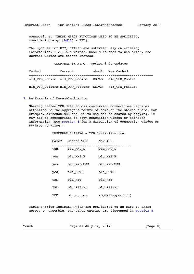
Internet-Draft TCP Control Block Interdependence January 2017
connections. [THESE MERGE FUNCTIONS NEED TO BE SPECIFIED, considering e.g. [DM16] - TBD].
The updates for RTT, RTTvar and ssthresh rely on existing information, i.e., old values. Should no such values exist, the current values are cached instead.
TEMPORAL SHARING - Option info Updates
Cached Current when? New Cached ---------------------------------------------------------------- old_TFO_Cookie old_TFO_Cookie ESTAB old_TFO_Cookie
old_TFO_Failure old_TFO_Failure ESTAB old_TFO_Failure
7. An Example of Ensemble Sharing
Sharing cached TCB data across concurrent connections requires attention to the aggregate nature of some of the shared state. For example, although MSS and RTT values can be shared by copying, it may not be appropriate to copy congestion window or ssthresh information (see section 8 for a discussion of congestion window or ssthresh sharing).
ENSEMBLE SHARING - TCB Initialization
Safe? Cached TCB New TCB ----------------------------------------- yes old_MMS_S old_MMS_S
yes old_MMS_R old_MMS_R
yes old_sendMSS old_sendMSS
yes old_PMTU old_PMTU
TBD old_RTT old_RTT
TBD old_RTTvar old_RTTvar
TBD old_option (option-specific)
Table entries indicate which are considered to be safe to share across an ensemble. The other entries are discussed in section 8.
Touch Expires July 12, 2017 [Page 8]

Internet-Draft TCP Control Block Interdependence January 2017
The table below gives an overview of option-specific information that is considered safe to share.
ENSEMBLE SHARING - Option info
Cached New ---------------------------------------- old_TFO_Cookie old_TFO_Cookie
old_TFO_Failure old_TFO_Failure
ENSEMBLE SHARING - Cache Updates
Safe? Cached TCB Current TCB when? New Cached TCB -------------------------------------------------------------- yes old_MMS_S curr_MMS_S OPEN curr_MMS_S
yes old_MMS_R curr_MMS_R OPEN curr_MMS_R
yes old_sendMSS curr_sendMSS MSSopt curr_sendMSS
yes old_PMTU curr_PMTU PMTUD curr_PMTU /PLPMTUD
TBD old_RTT curr_RTT update rtt_update(old,cur)
TBD old_RTTvar curr_RTTvar update rtt_update(old,cur)
varies old_option curr option (depends) (option specific)
For ensemble sharing, TCB information should be cached as early as possible, sometimes before a connection is closed. Otherwise, opening multiple concurrent connections may not result in TCB data sharing if no connection closes before others open. The amount of work involved in updating the aggregate average should be minimized, but the resulting value should be equivalent to having all values measured within a single connection. The function "rtt_update" in the ensemble sharing table indicates this operation, which occurs whenever the RTT would have been updated in the individual TCP connection. As a result, the cache contains the shared RTT variables, which no longer need to reside in the TCB [Ja86].
Congestion window size and ssthresh aggregation are more complicated in the concurrent case. When there is an ensemble of connections, we
Touch Expires July 12, 2017 [Page 9]

Internet-Draft TCP Control Block Interdependence January 2017
need to decide how that ensemble would have shared these variables, in order to derive initial values for new TCBs.
ENSEMBLE SHARING - Option info Updates
Cached Current when? New Cached ---------------------------------------------------------------- old_TFO_Cookie old_TFO_Cookie ESTAB old_TFO_Cookie
old_TFO_Failure old_TFO_Failure ESTAB old_TFO_Failure
Any assumption of this sharing can be incorrect, including this one, because identical endpoint address pairs may not share network paths. In current implementations, new congestion windows are set at an initial value of 4-10 segments [RFC3390][RFC6928], so that the sum of the current windows is increased for any new connection. This can have detrimental consequences where several connections share a highly congested link.
There are several ways to initialize the congestion window in a new TCB among an ensemble of current connections to a host, as shown below. Current TCP implementations initialize it to four segments as standard [rfc3390] and 10 segments experimentally [RFC6928] and T/TCP hinted that it should be initialized to the old window size [RFC1644]. In the former cases, the assumption is that new connections should behave as conservatively as possible. In the latter T/TCP case, no accommodation is made for concurrent aggregate behavior.
In either case, the sum of window sizes can increase, rather than remain constant. A different approach is to give each pending connection its "fair share" of the available congestion window, and let the connections balance from there. The assumption we make here is that new connections are implicit requests for an equal share of available link bandwidth, which should be granted at the expense of current connections. [TBD - a new method for safe congestion sharing will be described]
8. Compatibility Issues
For the congestion and current window information, the initial values computed by TCB interdependence may not be consistent with the long-term aggregate behavior of a set of concurrent connections between the same endpoints. Under conventional TCP congestion control, if a single existing connection has converged to a congestion window of 40 segments, two newly joining concurrent
Touch Expires July 12, 2017 [Page 10]
Internet-Draft TCP Control Block Interdependence January 2017
connections assume initial windows of 10 segments [RFC6928], and the current connection’s window doesn’t decrease to accommodate this additional load and connections can mutually interfere. One example of this is seen on low-bandwidth, high-delay links, where concurrent connections supporting Web traffic can collide because their initial windows were too large, even when set at one segment.
[TBD - this paragraph needs to be revised based on new recommendations] Under TCB interdependence, all three connections could change to use a congestion window of 12 (rounded down to an even number from 13.33, i.e., 40/3). This would include both increasing the initial window of the new connections (vs. current recommendations [RFC6928]) and decreasing the congestion window of the current connection (from 40 down to 12). This gives the new connections a larger initial window than allowed by [RFC6928], but maintains the aggregate. Depending on whether the previous connections were in steady-state, this can result in more bursty behavior, e.g., when previous connections are idle and new connections commence with a large amount of available data to transmit. Additionally, reducing the congestion window of an existing connection needs to account for the number of packets that are already in flight.
Because this proposal attempts to anticipate the aggregate steady- state values of TCB state among a group or over time, it should avoid the transient effects of new connections. In addition, because it considers the ensemble and temporal properties of those aggregates, it should also prevent the transients of short-lived or multiple concurrent connections from adversely affecting the overall network performance. There have been ongoing analysis and experiments to validate these assumptions. For example, [Ph12] recommends to only cache ssthresh for temporal sharing when flows are long. Sharing ssthresh between short flows can deteriorate the overall performance of individual connections[Ph12, Nd16], although this may benefit overall network performance. [TBD - the details of this issue need to be summarized and clarified herein].
[TBD - placeholder for corresponding RTT discussion]
Due to mechanisms like ECMP and LAG [RFC7424], TCP connections sharing the same host-pair may not always share the same path. This does not matter for host-specific information such as RWIN and TCP option state, such as TFOinfo. When TCB information is shared across different SYN destination ports, path-related information can be incorrect; however, the impact of this error is potentially diminished if (as discussed here) TCB sharing affects only the transient event of a connection start or if TCB information is
Touch Expires July 12, 2017 [Page 11]

Internet-Draft TCP Control Block Interdependence January 2017
shared only within connections to the same SYN destination port. In case of Temporal Sharing, TCB information could also become invalid over time. Because this is similar to the case when a connection becomes idle, mechanisms that address idle TCP connections (e.g., [RFC7661]) could also be applied to TCB cache management.
There may be additional considerations to the way in which TCB interdependence rebalances congestion feedback among the current connections, e.g., it may be appropriate to consider the impact of a connection being in Fast Recovery [RFC5861] or some other similar unusual feedback state, e.g., as inhibiting or affecting the calculations described herein.
TCP is sometimes used in situations where packets of the same host- pair always take the same path. Because ECMP and LAG examine TCP port numbers, they may not be supported when TCP segments are encapsulated, encrypted, or altered - for example, some Virtual Private Networks (VPNs) are known to use proprietary UDP encapsulation methods. Similarly, they cannot operate when the TCP header is encrypted, e.g., when using IPsec ESP. TCB interdependence among the entire set sharing the same endpoint IP addresses should work without problems under these circumstances. Moreover, measures to increase the probability that connections use the same path could be applied: e.g., the connections could be given the same IPv6 flow label. TCB interdependence can also be extended to sets of host IP address pairs that share the same network path conditions, such as when a group of addresses is on the same LAN (see Section 9).
It can be wrong to share TCB information between TCP connections on the same host as identified by the IP address if an IP address is assigned to a new host (e.g., IP address spinning, as is used by ISPs to inhibit running servers). It can be wrong if Network Address (and Port) Translation (NA(P)T) [RFC2663] or any other IP sharing mechanism is used. Such mechanisms are less likely to be used with IPv6. Other methods to identify a host could also be considered to make correct TCB sharing more likely. Moreover, some TCB information is about dominant path properties rather than the specific host. IP addresses may differ, yet the relevant part of the path may be the same.
9. Implications
There are several implications to incorporating TCB interdependence in TCP implementations. First, it may reduce the need for application-layer multiplexing for performance enhancement [RFC7231]. Protocols like HTTP/2 [RFC7540] avoid connection reestablishment costs by serializing or multiplexing a set of per-
Touch Expires July 12, 2017 [Page 12]

Internet-Draft TCP Control Block Interdependence January 2017
host connections across a single TCP connection. This avoids TCP’s per-connection OPEN handshake and also avoids recomputing MSS, RTT, and congestion windows. By avoiding the so-called, "slow-start restart," performance can be optimized. TCB interdependece can provide the "slow-start restart avoidance" of multiplexing, without requiring a multiplexing mechanism at the application layer.
TCB interdependence pushes some of the TCP implementation from the traditional transport layer (in the ISO model), to the network layer. This acknowledges that some state is in fact per-host-pair or can be per-path as indicated solely by that host-pair. Transport protocols typically manage per-application-pair associations (per stream), and network protocols manage per-host-pair and path associations (routing). Round-trip time, MSS, and congestion information could be more appropriately handled in a network-layer fashion, aggregated among concurrent connections, and shared across connection instances [RFC3124].
An earlier version of RTT sharing suggested implementing RTT state at the IP layer, rather than at the TCP layer [Ja86]. Our observations are for sharing state among TCP connections, which avoids some of the difficulties in an IP-layer solution. One such problem is determining the associated prior outgoing packet for an incoming packet, to infer RTT from the exchange. Because RTTs are still determined inside the TCP layer, this is simpler than at the IP layer. This is a case where information should be computed at the transport layer, but could be shared at the network layer.
Per-host-pair associations are not the limit of these techniques. It is possible that TCBs could be similarly shared between hosts on a subnet or within a cluster, because the predominant path can be subnet-subnet, rather than host-host. Additionally, TCB interdependence can be applied to any protocol with congestion state, including SCTP [RFC4960] and DCCP [RFC4340], as well as for individual subflows in Multipath TCP [RFC6824].
There may be other information that can be shared between concurrent connections. For example, knowing that another connection has just tried to expand its window size and failed, a connection may not attempt to do the same for some period. The idea is that existing TCP implementations infer the behavior of all competing connections, including those within the same host or subnet. One possible optimization is to make that implicit feedback explicit, via extended information associated with the endpoint IP address and its TCP implementation, rather than per-connection state in the TCB.
Touch Expires July 12, 2017 [Page 13]
Internet-Draft TCP Control Block Interdependence January 2017
Like its initial version in 1997, this document’s approach to TCB interdependence focuses on sharing a set of TCBs by updating the TCB state to reduce the impact of transients when connections begin or end. Other mechanisms have since been proposed to continuously share information between all ongoing communication (including connectionless protocols), updating the congestion state during any congestion-related event (e.g., timeout, loss confirmation, etc.) [RFC3124]. By dealing exclusively with transients, TCB interdependence is more likely to exhibit the same behavior as unmodified, independent TCP connections.
10. Implementation Observations
The observation that some TCB state is host-pair specific rather than application-pair dependent is not new and is a common engineering decision in layered protocol implementations. A discussion of sharing RTT information among protocols layered over IP, including UDP and TCP, occurred in [Ja86]. Although now deprecated, T/TCP was the first to propose using caches in order to maintain TCB states (see Appendix A for more information).
The table below describes the current implementation status for some TCB information in Linux kernel version 4.6, FreeBSD 10 and Windows (as of October 2016). In the table, "shared" only refers to temporal sharing.
Touch Expires July 12, 2017 [Page 14]

Internet-Draft TCP Control Block Interdependence January 2017
TCB data Status ----------------------------------------------------------- old MMS_S Not shared
old MMS_R Not shared
old_sendMSS Cached and shared in Linux (MSS)
old PMTU Cached and shared in FreeBSD and Windows (PMTU)
old_RTT Cached and shared in FreeBSD and Linux
old_RTTvar Cached and shared in FreeBSD
old TFOinfo Cached and shared in Linux and Windows
old_snd_cwnd Not shared
old_ssthresh Cached and shared in FreeBSD and Linux: FreeBSD: arithmetic mean of ssthresh and previous value if a previous value exists; Linux: depending on state, max(cwnd/2, ssthresh) in most cases
11. Security Considerations
These suggested implementation enhancements do not have additional ramifications for explicit attacks. These enhancements may be susceptible to denial-of-service attacks if not otherwise secured. For example, an application can open a connection and set its window size to zero, denying service to any other subsequent connection between those hosts.
TCB sharing may be susceptible to denial-of-service attacks, wherever the TCB is shared, between connections in a single host, or between hosts if TCB sharing is implemented within a subnet (see Implications section). Some shared TCB parameters are used only to create new TCBs, others are shared among the TCBs of ongoing connections. New connections can join the ongoing set, e.g., to optimize send window size among a set of connections to the same host.
Attacks on parameters used only for initialization affect only the transient performance of a TCP connection. For short connections, the performance ramification can approach that of a denial-of-
Touch Expires July 12, 2017 [Page 15]

Internet-Draft TCP Control Block Interdependence January 2017
service attack. E.g., if an application changes its TCB to have a false and small window size, subsequent connections would experience performance degradation until their window grew appropriately.
The solution is to limit the effect of compromised TCB values. TCBs are compromised when they are modified directly by an application or transmitted between hosts via unauthenticated means (e.g., by using a dirty flag). TCBs that are not compromised by application modification do not have any unique security ramifications. Note that the proposed parameters for TCB sharing are not currently modifiable by an application.
All shared TCBs MUST be validated against default minimum parameters before used for new connections. This validation would not impact performance, because it occurs only at TCB initialization. This limits the effect of attacks on new connections to reducing the benefit of TCB sharing, resulting in the current default TCP performance. For ongoing connections, the effect of incoming packets on shared information should be both limited and validated against constraints before use. This is a beneficial precaution for existing TCP implementations as well.
TCBs modified by an application SHOULD NOT be shared, unless the new connection sharing the compromised information has been given explicit permission to use such information by the connection API. No mechanism for that indication currently exists, but it could be supported by an augmented API. This sharing restriction SHOULD be implemented in both the host and the subnet. Sharing on a subnet SHOULD utilize authentication to prevent undetected tampering of shared TCB parameters. These restrictions limit the security impact of modified TCBs both for connection initialization and for ongoing connections.
Finally, shared values MUST be limited to performance factors only. Other information, such as TCP sequence numbers, when shared, are already known to compromise security.
12. IANA Considerations
There are no IANA implications or requests in this document.
This section should be removed upon final publication as an RFC.
Touch Expires July 12, 2017 [Page 16]

Internet-Draft TCP Control Block Interdependence January 2017
13. References
13.1. Normative References
[RFC793] Postel, Jon, "Transmission Control Protocol," Network Working Group RFC-793/STD-7, ISI, Sept. 1981.
[RFC1191] Mogul, J., Deering, S., "Path MTU Discovery," RFC 1191, Nov. 1990.
[RFC1981] McCann, J., Deering. S., Mogul, J., "Path MTU Discovery for IP version 6," RFC 1981, Aug. 1996.
[RFC2119] Bradner, S., "Key words for use in RFCs to Indicate Requirement Levels", BCP 14, RFC 2119, March 1997.
[RFC4821] Mathis, M., Heffner, J., "Packetization Layer Path MTU Discovery," RFC 4821, Mar. 2007.
[RFC7413] Cheng, Y., Chu, J., Radhakrishnan, S., Jain, A., "TCP Fast Open", RFC 7413, Dec. 2014.
13.2. Informative References
[Br02] Brownlee, N. and K. Claffy, "Understanding Internet Traffic Streams: Dragonflies and Tortoises", IEEE Communications Magazine p110-117, 2002.
[Be94] Berners-Lee, T., et al., "The World-Wide Web," Communications of the ACM, V37, Aug. 1994, pp. 76-82.
[Br94] Braden, B., "T/TCP -- Transaction TCP: Source Changes for Sun OS 4.1.3,", Release 1.0, USC/ISI, September 14, 1994.
[Co91] Comer, D., Stevens, D., Internetworking with TCP/IP, V2, Prentice-Hall, NJ, 1991.
[FreeBSD] FreeBSD source code, Release 2.10, http://www.freebsd.org/
[Ja86] Jacobson, V., (mail to public list "tcp-ip", no archive found), 1986.
[Nd16] Dukkipati, N., Yuchung C., and Amin V., "Research Impacting the Practice of Congestion Control." ACM SIGCOMM CCR (editorial).
Touch Expires July 12, 2017 [Page 17]

Internet-Draft TCP Control Block Interdependence January 2017
[DM16] Matz, D., "Optimize TCP’s Minimum Retransmission Timeout for Low Latency Environments", Master’s thesis, Technical University Munich, 2016.
[Ph12] Hurtig, P., Brunstrom, A., "Enhanced metric caching for short TCP flows," 2012 IEEE International Conference on Communications (ICC), Ottawa, ON, 2012, pp. 1209-1213.
[RFC1122] Braden, R. (ed), "Requirements for Internet Hosts -- Communication Layers", RFC-1122, Oct. 1989.
[RFC1644] Braden, R., "T/TCP -- TCP Extensions for Transactions Functional Specification," RFC-1644, July 1994.
[RFC1379] Braden, R., "Transaction TCP -- Concepts," RFC-1379, September 1992.
[RFC2663] Srisuresh, P., Holdrege, M., "IP Network Address Translator (NAT) Terminology and Considerations", RFC- 2663, August 1999.
[RFC3390] Allman, M., Floyd, S., Partridge, C., "Increasing TCP’s Initial Window," RFC 3390, Oct. 2002.
[RFC7231] Fielding, R., J. Reshke, Eds., "HTTP/1.1 Semantics and Content," RFC-7231, June 2014.
[RFC3124] Balakrishnan, H., Seshan, S., "The Congestion Manager," RFC 3124, June 2001.
[RFC4340] Kohler, E., Handley, M., Floyd, S., "Datagram Congestion Control Protocol (DCCP)," RFC 4340, Mar. 2006.
[RFC4960] Stewart, R., (Ed.), "Stream Control Transmission Protocol," RFC4960, Sept. 2007.
[RFC5861] Allman, M., Paxson, V., Blanton, E., "TCP Congestion Control," RFC 5861, Sept. 2009.
[RFC5925] Touch, J., Mankin, A., Bonica, R., "The TCP Authentication Option," RFC 5925, June 2010.
[RFC6824] Ford, A., Raiciu, C., Handley, M., Bonaventure, O., "TCP Extensions for Multipath Operation with Multiple Addresses," RFC 6824, Jan. 2013.
Touch Expires July 12, 2017 [Page 18]

Internet-Draft TCP Control Block Interdependence January 2017
[RFC6928] Chu, J., Dukkipati, N., Cheng, Y., Mathis, M., "Increasing TCP’s Initial Window," RFC 6928, Apr. 2013.
[RFC7424] Krishnan, R., Yong, L., Ghanwani, A., So, N., Khasnabish, B., "Mechanisms for Optimizing Link Aggregation Group (LAG) and Equal-Cost Multipath (ECMP) Component Link Utilization in Networks", RFC 7424, Jan. 2015
[RFC7540] Belshe, M., Peon, R., Thomson, M., "Hypertext Transfer Protocol Version 2 (HTTP/2)", RFC 7540, May 2015.
[RFC7661] Fairhurst, G., Sathiaseelan, A., Secchi, R., "Updating TCP to Support Rate-Limited Traffic", RFC 7661, Oct. 2015
14. Acknowledgments
The authors would like to thank for Praveen Balasubramanian for information regarding TCB sharing in Windows, and Yuchung Cheng, Lars Eggert, Ilpo Jarvinen and Michael Scharf for comments on earlier versions of the draft. This work has received funding from a collaborative research project between the University of Oslo and Huawei Technologies Co., Ltd., and is partly supported by USC/ISI’s Postel Center.
This document was prepared using 2-Word-v2.0.template.dot.
15. Change log
from -01 to -02:
- Stated that our OS implementation overview table only covers temporal sharing.
- Correctly reflected sharing of old_RTT in Linux in the implementation overview table.
- Marked entries that are considered safe to share with an asterisk (suggestion was to split the table)
- Discussed correct host identification: NATs may make IP addresses the wrong input, could e.g. use HTTP cookie.
- Included MMS_S and MMS_R from RFC1122; fixed the use of MSS and MTU
Touch Expires July 12, 2017 [Page 19]

Internet-Draft TCP Control Block Interdependence January 2017
- Added information about option sharing, listed options in the appendix
Authors’ Addresses
Joe Touch USC/ISI 4676 Admiralty Way Marina del Rey, CA 90292-6695 USA
Phone: +1 (310) 448-9151 Email: [email protected]
Michael Welzl University of Oslo PO Box 1080 Blindern Oslo N-0316 Norway
Phone: +47 22 85 24 20 Email: [email protected]
Safiqul Islam University of Oslo PO Box 1080 Blindern Oslo N-0316 Norway
Phone: +47 22 84 08 37 Email: [email protected]
Touch Expires July 12, 2017 [Page 20]
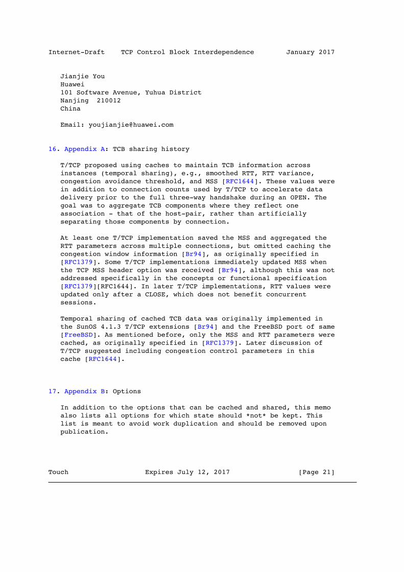
Internet-Draft TCP Control Block Interdependence January 2017
Jianjie You Huawei 101 Software Avenue, Yuhua District Nanjing 210012 China
Email: [email protected]
16. Appendix A: TCB sharing history
T/TCP proposed using caches to maintain TCB information across instances (temporal sharing), e.g., smoothed RTT, RTT variance, congestion avoidance threshold, and MSS [RFC1644]. These values were in addition to connection counts used by T/TCP to accelerate data delivery prior to the full three-way handshake during an OPEN. The goal was to aggregate TCB components where they reflect one association - that of the host-pair, rather than artificially separating those components by connection.
At least one T/TCP implementation saved the MSS and aggregated the RTT parameters across multiple connections, but omitted caching the congestion window information [Br94], as originally specified in [RFC1379]. Some T/TCP implementations immediately updated MSS when the TCP MSS header option was received [Br94], although this was not addressed specifically in the concepts or functional specification [RFC1379][RFC1644]. In later T/TCP implementations, RTT values were updated only after a CLOSE, which does not benefit concurrent sessions.
Temporal sharing of cached TCB data was originally implemented in the SunOS 4.1.3 T/TCP extensions [Br94] and the FreeBSD port of same [FreeBSD]. As mentioned before, only the MSS and RTT parameters were cached, as originally specified in [RFC1379]. Later discussion of T/TCP suggested including congestion control parameters in this cache [RFC1644].
17. Appendix B: Options
In addition to the options that can be cached and shared, this memo also lists all options for which state should *not* be kept. This list is meant to avoid work duplication and should be removed upon publication.
Touch Expires July 12, 2017 [Page 21]

Internet-Draft TCP Control Block Interdependence January 2017
Obsolete (MUST NOT keep state):
ECHO
ECHO REPLY
PO Conn permitted
PO service profile
CC
CC.NEW
CC.ECHO
Alt CS req
Alt CS data
No state to keep:
EOL
NOP
WS
SACK
TS
MD5
TCP-AO
EXP1
EXP2
MUST NOT keep state:
Touch Expires July 12, 2017 [Page 22]

Internet-Draft TCP Control Block Interdependence January 2017
Skeeter (DH exchange - might be obsolete, though)
Bubba (DH exchange - might really be obsolete, though)
Trailer CS
SCPS capabilities
S-NACK
Records boundaries
Corruption experienced
SNAP
TCP Compression
Quickstart response
UTO
MPTCP (can we cache when this fails?)
TFO success
MAY keep state:
MSS
TFO failure (so we don’t try again, since it’s optional)
MUST keep state:
TFP cookie (if TFO succeeded in the past)
Touch Expires July 12, 2017 [Page 23]