Embed Size (px)
Citation preview
T M
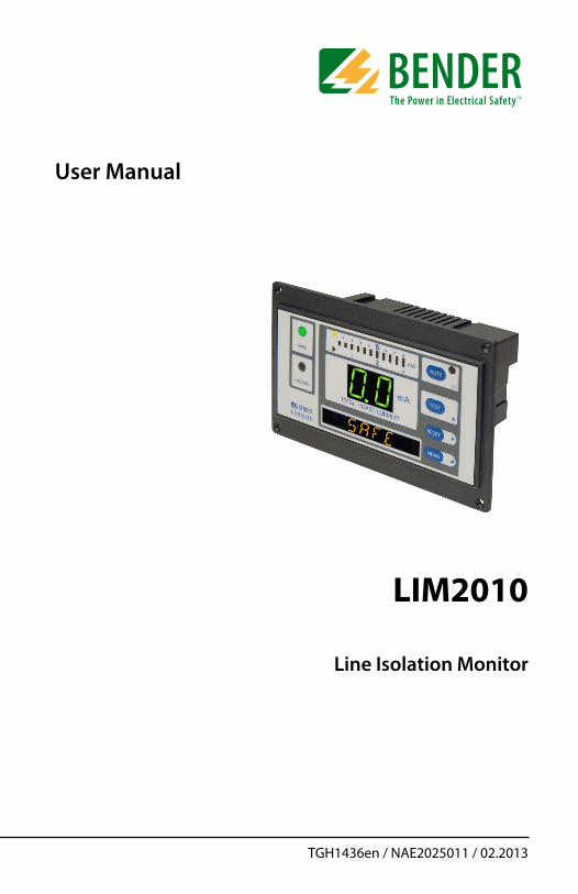
User Manual
LIM2010
Line Isolation Monitor
TGH1436en / NAE2025011 / 02.2013

Bender Inc.
USA:700 Fox ChaseCoatesville, PA 19320Toll Free: 800-356-4266Phone: 610-383-9200Fax: 610-466-2071E-mail: [email protected]
Canada:5810 Ambler Drive, Unit 1Mississauga, ON L4W 4J5Toll Free: 800-243-2438Phone: 905-602-9990Fax: 905-602-9960E-mail: [email protected]
Web: www.bender.org
NAE2025011, 02.2013Replaces NAE2025010, 11.2012
© Bender Inc.
All rights reserved.Content subject to change.
T M
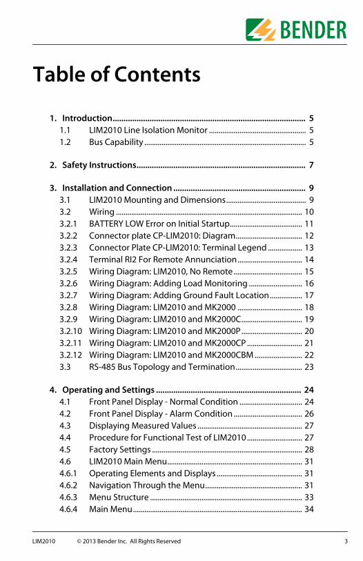
Table of Contents
1. Introduction......................................................................................... 51.1 LIM2010 Line Isolation Monitor ................................................... 51.2 Bus Capability ..................................................................................... 5
2. Safety Instructions.............................................................................. 7
3. Installation and Connection ............................................................. 93.1 LIM2010 Mounting and Dimensions.......................................... 93.2 Wiring .................................................................................................. 103.2.1 BATTERY LOW Error on Initial Startup...................................... 113.2.2 Connector plate CP-LIM2010: Diagram................................... 123.2.3 Connector Plate CP-LIM2010: Terminal Legend .................. 133.2.4 Terminal RI2 For Remote Annunciation.................................. 143.2.5 Wiring Diagram: LIM2010, No Remote .................................... 153.2.6 Wiring Diagram: Adding Load Monitoring ............................ 163.2.7 Wiring Diagram: Adding Ground Fault Location................. 173.2.8 Wiring Diagram: LIM2010 and MK2000 .................................. 183.2.9 Wiring Diagram: LIM2010 and MK2000C................................ 193.2.10 Wiring Diagram: LIM2010 and MK2000P................................ 203.2.11 Wiring Diagram: LIM2010 and MK2000CP ............................. 213.2.12 Wiring Diagram: LIM2010 and MK2000CBM ......................... 223.3 RS-485 Bus Topology and Termination................................... 23
4. Operating and Settings ................................................................... 244.1 Front Panel Display - Normal Condition ................................. 244.2 Front Panel Display - Alarm Condition .................................... 264.3 Displaying Measured Values ....................................................... 274.4 Procedure for Functional Test of LIM2010............................. 274.5 Factory Settings ............................................................................... 284.6 LIM2010 Main Menu....................................................................... 314.6.1 Operating Elements and Displays ............................................. 314.6.2 Navigation Through the Menu................................................... 314.6.3 Menu Structure ................................................................................ 334.6.4 Main Menu......................................................................................... 34
3LIM2010 © 2013 Bender Inc. All Rights Reserved

4.6.5 Menu: VALUES.................................................................................. 354.6.6 Menu: HISTORY................................................................................ 364.6.7 Menu: DATALOG (Logging for up to 300 data points) ...... 374.6.8 Menu: SETTING................................................................................. 384.6.9 Menu: SETTING/GENERAL............................................................ 394.6.10 Menu: SETTING/RELAY .................................................................. 404.6.11 Menu: SETTING/BUZZER............................................................... 424.6.12 Menu: SETTING/HISTORY ............................................................. 424.6.13 Menu: SETTING/DATALOG........................................................... 434.6.14 Menu: SETTING/INTERFACE (Bus Address) ............................ 434.6.15 Menu: SETTING/CLOCK ................................................................. 444.6.16 Menu: SETTING/PASSWORD ....................................................... 444.6.17 Menu: SETTING/FACTORY SETTING.......................................... 444.6.18 Menu: SETTING/SERVICE............................................................... 454.6.19 Menu: CONTROL/TEST .................................................................. 454.6.20 Menu: CONTROL/COMMUNICATION TEST ............................ 454.6.21 Menu: INFO........................................................................................ 46
5. Periodic Testing................................................................................ 47
6. Messages from the RS-485 Bus...................................................... 486.1 Alarm Messages............................................................................... 486.2 Operating Status Messages......................................................... 49
7. Technical Data .................................................................................. 507.1 LIM2010.............................................................................................. 507.2 Connector Plate............................................................................... 547.3 Current Transformers .................................................................... 547.3.1 Technical Data: STW3 .................................................................... 547.3.2 Technical Data: STW4 .................................................................... 557.3.3 General Data: STW3 / STW4......................................................... 557.4 Error Codes and Troubleshooting............................................. 567.5 Dimensions: STW3 / STW4 ........................................................... 577.6 Ordering Information .................................................................... 58
4 LIM2010 © 2013 Bender Inc. All Rights Reserved

Introduction
1. Introduction
1. 1 LIM2010 Line Isolation Monitor
The Line Isolation Monitor (LIM) LIM2010 measures the impedance of the con-nected isolated power system to ground. The LIM then uses this value to calcu-late the maximum Total Hazard Current (THC), which is displayed on the front of the LIM continuously in milliamperes (mA). Total Hazard Current is the calcu-lated maximum fault current passing through a human body to ground if live conductors of the isolated power system were touched.
In addition to the continuously operating digital display, a colored LED bar graph provides indication of Total Hazard Current in the system. The words “SAFE” and “HAZARD” are displayed prominently on the front of the device, coupled with green and red LEDs.
The device is designed to monitor isolated power systems with voltages of 100 to 240 VAC at 50 Hz or 60 Hz without the use of a separate supply voltage.
1. 2 Bus Capability
References to devices with “bus capability” will appear throughout this man-ual. The LIM2010, as well as some remote indicators, feature a two-way RS-485 communication system utilizing a proprietary protocol referred to as the BMS bus. Devices utilizing this RS-485 communication bus generally require less connections and can communicate more information remotely.If remote indicators are utilized with the LIM2010, certain instructions may change based on whether the remote has or does not have RS-485 capability. Ensure that you are following the proper instructions when wiring and setting up the device.
Remotes with no bus capability: MK2000(C)(P) series (any combination)Remotes with bus capability: MK2000CBM, MK2430, MK800
For more information on this topic, refer to the wiring diagram specific to the utilized remote indicator.
5LIM2010 © 2013 Bender Inc. All Rights Reserved

Introduction
This page intentionally left blank.
6 LIM2010 © 2013 Bender Inc. All Rights Reserved
Safety Instructions
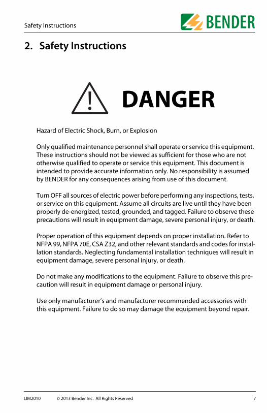
2. Safety Instructions
Hazard of Electric Shock, Burn, or Explosion
Only qualified maintenance personnel shall operate or service this equipment. These instructions should not be viewed as sufficient for those who are not otherwise qualified to operate or service this equipment. This document is intended to provide accurate information only. No responsibility is assumed by BENDER for any consequences arising from use of this document.
Turn OFF all sources of electric power before performing any inspections, tests, or service on this equipment. Assume all circuits are live until they have been properly de-energized, tested, grounded, and tagged. Failure to observe these precautions will result in equipment damage, severe personal injury, or death.
Proper operation of this equipment depends on proper installation. Refer to NFPA 99, NFPA 70E, CSA Z32, and other relevant standards and codes for instal-lation standards. Neglecting fundamental installation techniques will result in equipment damage, severe personal injury, or death.
Do not make any modifications to the equipment. Failure to observe this pre-caution will result in equipment damage or personal injury.
Use only manufacturer’s and manufacturer recommended accessories with this equipment. Failure to do so may damage the equipment beyond repair.
! DANGER
7LIM2010 © 2013 Bender Inc. All Rights Reserved

Safety Instructions
This page intentionally left blank.
8 LIM2010 © 2013 Bender Inc. All Rights Reserved

Installation and Connection
3. Installation and Connection
3. 1 LIM2010 Mounting and Dimensions
The front plate provides four holes with a diameter of 1/8” (3.2 mm) for screw mounting. Use the four provided mounting screws. Use minimum 2.6 lb-in (0.3 N-m), maximum 3.5 lb-in (0.4 N-m) tightening torque. Before mounting, plug the connector plate into the LIM2010.Dimensions shown below are in inches (mm).
7“ (178)
5.3“ (134.5) 3.1“ (79.5)
2.4“
(62)
4.4“
(112
)
3.2“
(81)
4“ (1
01.5
)
6.5“ (165)
9LIM2010 © 2013 Bender Inc. All Rights Reserved

Installation and Connection
3. 2 Wiring
The LIM2010 connects to a connector plate assembly. Follow these instruc-tions to ensure proper connection and installation of the Line Isolation Moni-tor.Remotes that are labeled as having “bus capability” have the ability to connect to the LIM2010 via a two-way RS-485 communication protocol.
• Locate the proper wiring diagram from the table below. Note which remote indicator has been supplied with the LIM2010. Wiring instructions vary based on this combination.
• Before mounting the LIM, plug the connector plate into the LIM2010.• Make the connections according to the respective wiring diagram.• Turn ON power to the LIM2010. If no error messages are displayed, the
LIM2010 is operating properly. Refer to section 4 for more detailed infor-mation.
For connecting to MK2430 or MK800 remote indicating stations, refer to their respective user manuals for more information. Refer to Section 3.3 for making RS-485 connections to the LIM2010.NOTE: The connector plate must be installed in a grounded, metallic enclo-sure.
Remote Bus Compatible Wiring Diagram
No remote - page 15
MK2000 - page 18
MK2000C - page 19
MK2000P - page 20
MK2000CP - page 21
MK2000CBM - page 22
DANGERWhen applying power to the LIM, do not apply a voltage higher than 240 VAC. Failure to observe this precaution will result in equipment damage, severe personal injury, or death.
10 LIM2010 © 2013 Bender Inc. All Rights Reserved

Installation and Connection
3.2.1 BATTERY LOW Error on Initial StartupUpon energizing the LIM2010 for the first time, a “BATTERY LOW” error mes-sage may appear. To clear this error, set the date and time on the device by referring to section 4.6.15, “Menu: SETTING / CLOCK.” This will clear the error. The internal battery used for clock management will charge during normal operation.
11LIM2010 © 2013 Bender Inc. All Rights Reserved

Installation and Connection
3.2.2 Connector plate CP-LIM2010: DiagramNOTE: The connector plate must only be installed in a grounded, metallic enclosure.
Terminal legend is found on the following page.
L1L212VDC CMABRI1K1/NCK1/COMK1/NOSAFE
HAZARD
RI2
LIMGNDTEST1S1Z1/M+1S2Z2/M-K2/COMK2/NCK2/NO
GND2
A B
1S11S2
Z1 / M+Z2 / M-
No Connec.K2 / Comm.
K2 / NCK2 / NO
12 LIM2010 © 2013 Bender Inc. All Rights Reserved
Installation and Connection
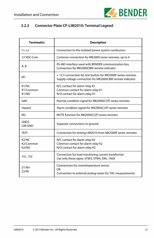
3.2.3 Connector Plate CP-LIM2010: Terminal Legend
Terminal(s) Description
L1, L2 Connection to the isolated power system conductors.
12 VDC Com. Common connection for MK2000 series remotes, up to 4
A, BRS-485 interface used with BENDER communication busConnection for MK2000CBM remote indicator
RI1+ 12 V connection for test button for MK2000P series remotesSupply voltage connection for MK2000CBM remote indicator
K1/NCK1/CommonK1/NO
N/C contact for alarm relay K1Common contact for alarm relay K1N/O contact for alarm relay K1
Safe Normal condition signal for MK2000(C)(P) series remotes
Hazard Alarm condition signal for MK2000(C)(P) series remotes
RI2 MUTE function for MK2000(C)(P) series remotes
GND2LIM GND
Separate connections to ground
TEST Connection for testing LIM2010 from MK2000P series remotes
K2/NCK2/CommonK2/NO
N/C contact for alarm relay K2Common contact for alarm relay K2N/O contact for alarm relay K2
1S1, 1S2Connection for load monitoring current transformerUse only these types: STW3, STW4, SWL-100A
Z1/M+Z2/M-
Connections for overtemperature sensorORConnection to external analog meter for THC measurements
13LIM2010 © 2013 Bender Inc. All Rights Reserved

Installation and Connection
3.2.4 Terminal RI2 For Remote AnnunciationRemote indicators that do not have bus capability may be muted collectively by connecting terminals 7 and 8 on the remote to terminal RI2 on the LIM2010. Regardless of wiring configuration, each respective device is able to mute itself. Wiring between the remote and the LIM2010 will affect whether a partic-ular device will mute more than just itself. Refer to the table below for details.
X = Terminal connected
LIM2010 MK2000 (C) (P)
Terminal RI2
Terminal 7
Terminal 8
Mute Function
- - - Only the local device will be muted
X X - LIM mute button mutes both LIM and remote
X - X Remote mute button mutes both LIM and remote
X X X Both mute buttons will mute both devices
14 LIM2010 © 2013 Bender Inc. All Rights Reserved
Installation and Connection
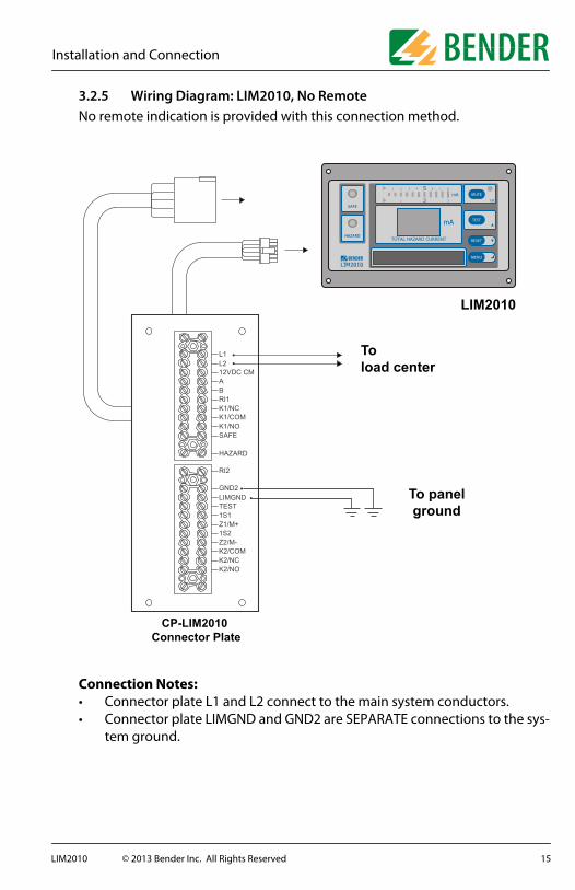
3.2.5 Wiring Diagram: LIM2010, No RemoteNo remote indication is provided with this connection method.
Connection Notes:• Connector plate L1 and L2 connect to the main system conductors.• Connector plate LIMGND and GND2 are SEPARATE connections to the sys-
tem ground.
CP-LIM2010 Connector Plate
To load center
SAFE
HAZARD
MUTEESC
TEST
RESET
MENU
LIM2010
To panelground
L1L212VDC CMABRI1K1/NCK1/COMK1/NOSAFE
HAZARD
RI2
LIMGNDTEST1S1Z1/M+1S2Z2/M-K2/COMK2/NCK2/NO
GND2
15LIM2010 © 2013 Bender Inc. All Rights Reserved
Installation and Connection
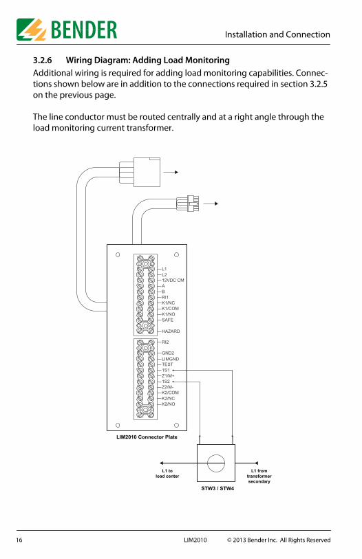
3.2.6 Wiring Diagram: Adding Load MonitoringAdditional wiring is required for adding load monitoring capabilities. Connec-tions shown below are in addition to the connections required in section 3.2.5 on the previous page.
The line conductor must be routed centrally and at a right angle through the load monitoring current transformer.
STW3 / STW4
LIM2010 Connector Plate
L1 fromtransformersecondary
L1 toload center
L1L212VDC CMABRI1K1/NCK1/COMK1/NOSAFE
HAZARD
RI2
LIMGNDTEST1S1Z1/M+1S2Z2/M-K2/COMK2/NCK2/NO
GND2
16 LIM2010 © 2013 Bender Inc. All Rights Reserved

Installation and Connection
3.2.7 Wiring Diagram: Adding Ground Fault LocationAdding ground fault location requires the following modules:
• EDS461-D-2 ground fault location module. Each module monitors up to twelve (12) branches - monitoring additional branches requires additional modules.
• W10-8000 current transformer (one required per branch)
OR
• EDS151 ground fault location module. EDS151 modules have integrated current transformers. One module can monitor up to six (6) separate branches. Monitoring additional branches requires additional EDS151 modules.
• MK2430 or MK800 remote indicating station. Only one required even if multiple location modules are utilized.
Ground fault location modules connect to the system’s LIM2010 via the BENDER RS-485 communication bus. Multiple ground fault location modules may be connected to a single LIM2010. For more information on connecting RS-485 communicating equipment to the LIM2010, refer to section 3.3.
For information on installing ground faut location modules, refer to the respective EDS461 / EDS151 user manuals.
17LIM2010 © 2013 Bender Inc. All Rights Reserved

Installation and Connection
3.2.8 Wiring Diagram: LIM2010 and MK2000This remote provides a SAFE LED, a HAZARD LED, and a mute button / LED.
Connection Notes:• Connector plate L1 and L2 connect to the main system conductors.• Connector plate LIMGND and GND2 are SEPARATE connections to the sys-
tem ground.• Connector plate Safe, Hazard, and 12 VDC COM connect to the respective
terminals on the remote.• Connector plate RI2 connection is required for system muting.
CP-LIM2010 Connector Plate
To load center
SAFE
HAZARD
MUTEESC
TEST
RESET
MENU
LIM2010
To panelground
MK2000
L1L212VDC CMABRI1K1/NCK1/COMK1/NOSAFE
HAZARD
RI2
LIMGNDTEST1S1Z1/M+1S2Z2/M-K2/COMK2/NCK2/NO
GND2
18 LIM2010 © 2013 Bender Inc. All Rights Reserved

Installation and Connection
3.2.9 Wiring Diagram: LIM2010 and MK2000CThis remote provides a SAFE LED, a HAZARD LED, a transformer overload LED, and a mute button / LED.
Connection Notes:• Connector plate L1 and L2 connect to the main system conductors.• Connector plate LIMGND and GND2 are SEPARATE connections to the sys-
tem ground.• Connector plate Safe, Hazard, and 12 VDC COM connect to the respective
terminals on the remote.• Connector plate RI2 connection is required for system muting.• For load monitoring, only current transformer types STW3, STW4, and
SWL-100A may be used.• The factory setting in the LIM2010 for the current transformer is STW3.
CP-LIM2010 Connector Plate
To load center
SAFE
HAZARD
MUTEESC
TEST
RESET
MENU
LIM2010
To panelground
MK2000C
STW3 / STW4
L1 fromtransformersecondary
L1 toload center
L1L212VDC CMABRI1K1/NCK1/COMK1/NOSAFE
HAZARD
RI2
LIMGNDTEST1S1Z1/M+1S2Z2/M-K2/COMK2/NCK2/NO
GND2
19LIM2010 © 2013 Bender Inc. All Rights Reserved
Installation and Connection
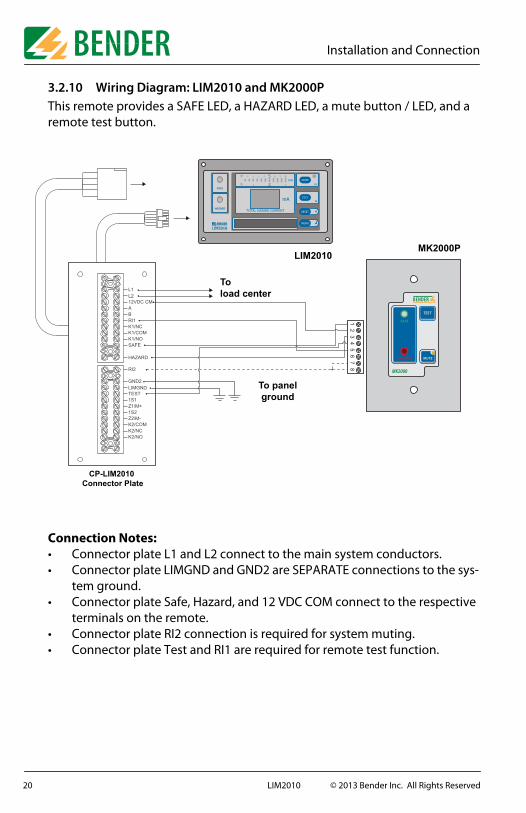
3.2.10 Wiring Diagram: LIM2010 and MK2000PThis remote provides a SAFE LED, a HAZARD LED, a mute button / LED, and a remote test button.
Connection Notes:• Connector plate L1 and L2 connect to the main system conductors.• Connector plate LIMGND and GND2 are SEPARATE connections to the sys-
tem ground.• Connector plate Safe, Hazard, and 12 VDC COM connect to the respective
terminals on the remote.• Connector plate RI2 connection is required for system muting.• Connector plate Test and RI1 are required for remote test function.
CP-LIM2010 Connector Plate
To load center
SAFE
HAZARD
MUTEESC
TEST
RESET
MENU
LIM2010
To panelground
MK2000P
L1L212VDC CMABRI1K1/NCK1/COMK1/NOSAFE
HAZARD
RI2
LIMGNDTEST1S1Z1/M+1S2Z2/M-K2/COMK2/NCK2/NO
GND2
20 LIM2010 © 2013 Bender Inc. All Rights Reserved

Installation and Connection
3.2.11 Wiring Diagram: LIM2010 and MK2000CPThis remote provides a SAFE LED, a HAZARD LED, a transformer overload LED, a mute button / LED, and a remote test button.
Connection Notes:• Connector plate L1 and L2 connect to the main system conductors.• Connector plate LIMGND and GND2 are SEPARATE connections to the sys-
tem ground.• Connector plate Safe, Hazard, and 12 VDC COM connect to the respective
terminals on the remote.• Connector plate RI2 connection is required for system muting.• Connector plate Test and RI1 are required for remote test function.• For load monitoring, only current transformer types STW3, STW4, and
SWL-100A may be used.• The factory setting in the LIM2010 for the current transformer is STW3.
CP-LIM2010 Connector Plate
To load center
SAFE
HAZARD
MUTEESC
TEST
RESET
MENU
LIM2010
To panelground
MK2000CP
STW3 / STW4
L1 fromtransformersecondary
L1 toload center
L1L212VDC CMABRI1K1/NCK1/COMK1/NOSAFE
HAZARD
RI2
LIMGNDTEST1S1Z1/M+1S2Z2/M-K2/COMK2/NCK2/NO
GND2
21LIM2010 © 2013 Bender Inc. All Rights Reserved

Installation and Connection
3.2.12 Wiring Diagram: LIM2010 and MK2000CBMThis remote provides a SAFE LED, a HAZARD LED, a transformer overload LED, a mute button / LED, a remote test button, and two digital displays showing Total Hazard Current and transformer overload.
Connection Notes:• Connector plate L1 and L2 connect to the main system conductors.• Connector plate LIMGND and GND2 are SEPARATE connections to the sys-
tem ground.• Connector plate Safe, Hazard, and 12 VDC COM connect to the respective
terminals on the remote.• Connector plate RI2 connection is required for system muting.• Connector plate Test and RI1 are required for remote test function.• For load monitoring, only current transformer types STW3, STW4, and
SWL-100A may be used.• The factory setting in the LIM2010 for the current transformer is STW3.• Refer to Section 3.3 for additional requirements for setting up a BENDER
RS-485 communication bus.
STW3 / STW4
CP-LIM2010 Connector Plate
L1 fromtransformersecondary
L1 toload center
To load center
RS-485 cable: twisted, shielded pair
MK2000CBM
120 �Termination
Resistor
SAFE
HAZARD
MUTEESC
TEST
RESET
MENU
LIM2010
To panelground bus
L1L212VDC CMABRI1K1/NCK1/COMK1/NOSAFE
HAZARD
RI2
LIMGNDTEST1S1Z1/M+1S2Z2/M-K2/COMK2/NCK2/NO
GND2
22 LIM2010 © 2013 Bender Inc. All Rights Reserved

Installation and Connection
3. 3 RS-485 Bus Topology and Termination
NOTE: This section only applies when one or more of the following devices are utilized in combination with the LIM2010:
• Remote indicators with bus capability• Ground fault location modules
For communication purposes, devices are connected to each other in an RS-485 chain. A topology example is given below. Use AWG 20 RS-485 cable. Node limits and cable distances according to RS-485 standards apply.
Each device requires a unique address on the BENDER communication bus. Refer to section 4.6.XX for changing this setting on the LIM2010. For other devices, refer to their respective user manual.
Devices at the beginning and end of the chain require termination. Termina-tion is accomplished by either placing a 120 ohm resistor across terminals A and B, or changing the Ron DIP switch to ON (if it is available).
If the LIM2010 is at the beginning or end of the RS-485 chain, change the Ron DIP switch shown below to ON. Otherwise, change it to OFF.
���������
� ����� ���� �������
���������
�����������
� � � � �� � �
������� ������
� ��
��� �
SAFE
HAZARD
MUTEESC
TEST
RESET
MENU
RS-485Termination
Roff on
23LIM2010 © 2013 Bender Inc. All Rights Reserved
Operating and Settings
4. Operating and Settings
4. 1 Front Panel Display - Normal Condition
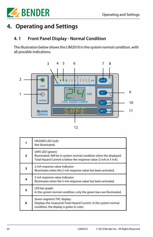
The illustration below shows the LIM2010 in the system normal condition, with all possible indications.
1HAZARD LED (red):Not illuminated.
2SAFE LED (green):Illuminated. Will be in system normal condition when the displayed Total Hazard Current is below the response value (2 mA or 5 mA).
32 mA response value indicator:Illuminates when the 2 mA response value has been activated.
45 mA response value indicator:Illuminates when the 5 mA response value has been activated.
5LED bar graph:In the system normal condition, only the green bars are illuminated.
6Seven-segment THC display:Displays the measured Total Hazard Current. In the system normal condition, the display is green in color.
SAFE
HAZARD
MUTEESC
TEST
RESET
MENU
1
2
3 4 5 6 7 8
9
10
11
12
24 LIM2010 © 2013 Bender Inc. All Rights Reserved

Operating and Settings
7MUTE buttonESC key: Moves back an option in the built-in menu.
8Mute LED:Not illuminated in the system normal condition.
9TEST Button: Activates the built-in self-test.UP key: Moves up in the menu and decreases values where applica-ble.
10DOWN key: Moves down in the menu and increases values where applicable.
11MENU key: Enters the main menu.ENTER key: Confirms settings and entries.
12Digital display:Reads SAFE in the system normal condition. When in the menu, dis-plays menu options.
25LIM2010 © 2013 Bender Inc. All Rights Reserved

Operating and Settings
4. 2 Front Panel Display - Alarm Condition
When the measured Total Hazard Current exceeds the set response value (2 mA or 5 mA), the LIM2010 will go into the alarm condition. When this occurs, the audible alarm will sound, as well as the following:
1HAZARD LED (red):Illuminates.
2SAFE LED (green):No longer illuminated.
3LED bar graph:In the alarm condition, the red bars will illuminate.
4Seven-segment THC display:Displays the measured Total Hazard Current. In the alarm condition, the display is red in color.
5MUTE button:Pressing the MUTE button will silence the audible alarm and activate the yellow MUTE LED.
6MUTE LED:Will illuminate after the MUTE button is pressed.
7Digital display:Reads HAZARD in the alarm condition.
SAFE
HAZARD
MUTEESC
TEST
RESET
MENU
1
2
3 4 5 6
7
26 LIM2010 © 2013 Bender Inc. All Rights Reserved

Operating and Settings
4. 3 Displaying Measured Values
The Total Hazard Current is displayed in real-time on the numeric display in the middle of the frontplate. For retrieving other measured values, such as load current or impedance, refer to the menu item “1.Values.” For details about the submenu VALUES, refer to section 4.6.5.
4. 4 Procedure for Functional Test of LIM2010
The LIM2010 may be tested while the isolated power system is online. Press the TEST button for approximately two seconds to begin the functional test. The following will occur:
• The entire LED bar graph will illuminate.• The digital display at the bottom of the frontplate will display **TEST**.• The digital display will flash.• The audible buzzer will sound.• The HAZARD LED will illuminate.• If no fault is present in the system, the text ***OK*** will appear on the
digital display. The device will then return to the system normal condition. The text **SAFE** will display on the digital display and the SAFE LED will illuminate.
BENDER recommends pressing the TEST button at least monthly to ensure proper operation of the LIM2010.
27LIM2010 © 2013 Bender Inc. All Rights Reserved
Operating and Settings
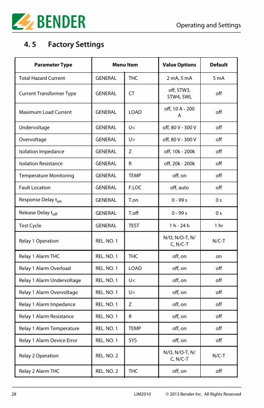
4. 5 Factory Settings
Parameter Type Menu Item Value Options Default
Total Hazard Current GENERAL THC 2 mA, 5 mA 5 mA
Current Transformer Type GENERAL CToff, STW3,
STW4, SWLoff
Maximum Load Current GENERAL LOADoff, 10 A - 200
Aoff
Undervoltage GENERAL U< off, 80 V - 300 V off
Overvoltage GENERAL U> off, 80 V - 300 V off
Isolation Impedance GENERAL Z off, 10k - 200k off
Isolation Resistance GENERAL R off, 20k - 200k off
Temperature Monitoring GENERAL TEMP off, on off
Fault Location GENERAL F.LOC off, auto off
Response Delay ton GENERAL T.on 0 - 99 s 0 s
Release Delay toff GENERAL T.off 0 - 99 s 0 s
Test Cycle GENERAL TEST 1 h - 24 h 1 hr
Relay 1 Operation REL. NO. 1N/O, N/O-T, N/
C, N/C-TN/C-T
Relay 1 Alarm THC REL. NO. 1 THC off, on on
Relay 1 Alarm Overload REL. NO. 1 LOAD off, on off
Relay 1 Alarm Undervoltage REL. NO. 1 U< off, on off
Relay 1 Alarm Overvoltage REL. NO. 1 U> off, on off
Relay 1 Alarm Impedance REL. NO. 1 Z off, on off
Relay 1 Alarm Resistance REL. NO. 1 R off, on off
Relay 1 Alarm Temperature REL. NO. 1 TEMP off, on off
Relay 1 Alarm Device Error REL. NO. 1 SYS off, on off
Relay 2 Operation REL. NO. 2N/O, N/O-T, N/
C, N/C-TN/C-T
Relay 2 Alarm THC REL. NO. 2 THC off, on off
28 LIM2010 © 2013 Bender Inc. All Rights Reserved

Operating and Settings
Relay 2 Alarm Overload REL. NO. 2 LOAD off, on on
Relay 2 Alarm Undervoltage REL. NO. 2 U< off, on on
Relay 2 Alarm Overvoltage REL. NO. 2 U> off, on on
Relay 2 Alarm Impedance REL. NO. 2 Z off, on on
Relay 2 Alarm Resistance REL. NO. 2 R off, on on
Relay 2 Alarm Temperature REL. NO. 2 TEMP off, on on
Relay 2 Alarm Device Error REL. NO. 2 SYS off, on on
Buzzer Volume BUZZER VOL High, Low High
System Mute BUZZER SY.MU off, on on
Buzzer Alarm Overload BUZZER LOAD off, on on
Buzzer Alarm Undervoltage BUZZER U< off, on on
Buzzer Alarm Overvoltage BUZZER U> off, on on
Buzzar Alarm Impedance BUZZER Z off, on on
Buzzer Alarm Resistance BUZZER R off, on on
Buzzer Alarm Temperature BUZZER TEMP off, on on
Buzzer Alarm Device Error BUZZER SYS off, on on
Data Log. Chan. THC Change DATALOG CHAN.THC 0% - 100% 10%
Data Log. Chan. THC O/W DATALOG CHAN.THC no, yes no
Data. Log. Chan. U.12 Change DATALOG CHAN.U.12 0% - 100% 10%
Data Log. Chan. U.12 O/W DATALOG CHAN.U.12 no, yes no
Data Log. Chan. U.1E Change DATALOG CHAN.U.1E 0% - 100% 10%
Data Log. Chan. U.1E O/W DATALOG CHAN.U.1E no, yes no
Data Log. Chan. U.2E Change DATALOG CHAN.U.2E 0% - 100% 10%
Data Log. Chan. U.2E O/W DATALOG CHAN.U.2E no, yes no
Data Log. Chan. Z Change DATALOG CHAN.Z 0% - 100% 10%
Data Log. Chan. Z O/W DATALOG CHAN.Z no, yes no
Parameter Type Menu Item Value Options Default
29LIM2010 © 2013 Bender Inc. All Rights Reserved

Operating and Settings
Data Log. Chan. R Change DATALOG CHAN.R 0% - 100% 10%
Data Log. Chan. R O/W DATALOG CHAN.R no, yes no
Data Log. Chan. I.1 Change DATALOG CHAN.I.1 0% - 100% 10%
Data Log. Chan. I.1 O/W DATALOG CHAN.I.1 no, yes no
Data Log. Chan. I.2 Change DATALOG CHAN.I.2 0% - 100% 10%
Data Log. Chan. I.2 O/W DATALOG CHAN.I.2 no, yes no
Data Log. Chan. I.3 Change DATALOG CHAN.I.3 0% - 100% 10%
Data Log. Chan. I.3 O/W DATALOG CHAN.I.3 no, yes no
RS-485 (BMS) Bus Address INTRFCE ADR. 1 - 90 1 (Master)
Daylight Savings Time Change CLOCK DST off, auto auto
Password PASSWRD PSWD*** 0 - 999 807
Password Status (Lock) PASSWRD LOCK off, on on
Parameter Type Menu Item Value Options Default
30 LIM2010 © 2013 Bender Inc. All Rights Reserved
Operating and Settings
4. 6 LIM2010 Main Menu
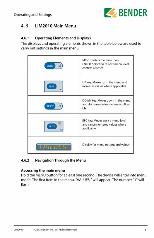
4.6.1 Operating Elements and DisplaysThe displays and operating elements shown in the table below are used to carry out settings in the main menu.
4.6.2 Navigation Through the Menu
Accessing the main menuHold the MENU button for at least one second. The device will enter into menu mode. The first item in the menu, “VALUES,” will appear. The number “1” will flash.
MENU: Enters the main menuENTER: Selection of next menu level, confirms entries
UP key: Moves up in the menu and increases values where applicable
DOWN key: Moves down in the menu and decreases values where applica-ble
ESC key; Moves back a menu level and cancels entered values where applicable
Display for menu options and values
MENU
TEST
RESET
MUTEESC
31LIM2010 © 2013 Bender Inc. All Rights Reserved

Operating and Settings
Entering the password prior to menu navigationMost menu options are password protected. Follow the below procedure to enter the password:
• A flashing number indicates the current focus.• Use the UP/DOWN keys to select the first correct number.• Confirm with the ENTER key.• Repeat until the last number is confirmed.• Settings may be modified without entering the password until the main
menu is exited. Entering the menu after exiting will require a re-entry of the password.
32 LIM2010 © 2013 Bender Inc. All Rights Reserved
Operating and Settings
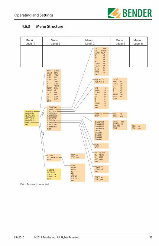
4.6.3 Menu Structure
1.GENERAL2.RELAY3.BUZZER4.HISTORY 5.DATALOG6.INTRFCE7.CLOCK8.PASSWRD9.FACT.SETA.SERVICEEXIT
TEST noTEST yes
THC 2.3mALOAD 60%U.12 110VU.1E 55VU.2E 55V���� � �������� � ��C 100nFTEMP O.K.F.LOC offSYS O.K.I.1 60A I.2 0.0A I.3 0.0A EXIT
THC 5mACT STW3 LOAD 100AU< offU> offZ offR offTEMP on F.LOC off T. on 0sT. off 0sTEST 1hEXIT
N/C-TTHC onLOAD off U< offU> offZ offR offTEMP off SYS offEXIT
VOL HISY.MU onLOAD on U< onU> onZ onR onTEMP on SYS onEXIT
DELETEEXIT
ADR. 1EXIT
Tm 10.34ADy 12/23Yr 2008DST autoEXIT
PSWD ***LOCK offEXIT
F.SET noF.SET yes
CHAN.THCCHAN.U.12CHAN.U.1ECHAN.U.2ECHAN.ZCHAN.RCHAN.I.1CHAN.I.2CHAN.I.3
DEL. noDEL. yes
DEL. noDEL. yes
CHNG 10%OVWR noDELETEEXIT
REL. NC. 1REL. NO. 2
1.VALUES2.HISTORY 3.DATALOG4.SETTING5.CONTROL6.INFOEXIT
1.THC2.LOAD3.U.126.Z7.R9.TEMP11.SYSEXIT
1.TEST2.COM.TESTEXIT
LIM2010OPT-DCFD301V1.0xD306V1.0xEXIT
PW
PW
PW = Password protected
MenuLevel 1
MenuLevel 2
MenuLevel 3
MenuLevel 4
MenuLevel 5
33LIM2010 © 2013 Bender Inc. All Rights Reserved

Operating and Settings
4.6.4 Main MenuTo go back a step in the menu, press the MUTE/ESC key.
MENULevel 1
Description Page
EXIT
1. VALUESDisplay all measured values in real-time
XX
2. HISTORYDisplay history of alarm mes-sages
XX
3. DATALOGGERData logging of selected parameters
XX
4. SETTING Change settings XX
5. CONTROL Begin BMS or device test XX
6. INFO Display device information XX
EXIT
����������
34 LIM2010 © 2013 Bender Inc. All Rights Reserved

Operating and Settings
4.6.5 Menu: VALUESThis menu indicates the values being measured in real-time.
MENULevel 1
MENULevel 2
Description
EXIT
1. VALUES THC 2.3mA Total Hazard Current
LOAD 60% Max. load current [%]
U.12 110V Voltage between L1 and L2
U.1E 55V Voltage between L1 and ground
U.2E 55V Voltage between L2 and ground
Z 24k Isolation impedance
R 37k Isolation resistance
C 100nF Leakage capacitance
TEMP O.K. Transformer temperature indication
F.LOC off Status of the location test generator
SYS O.K. Status of the device
I.1 60A Load current measured from CT 1
I.2 0.0A Load current measured from CT 2
I.3 0.0A Load current measured from CT 3
EXIT
35LIM2010 © 2013 Bender Inc. All Rights Reserved
Operating and Settings
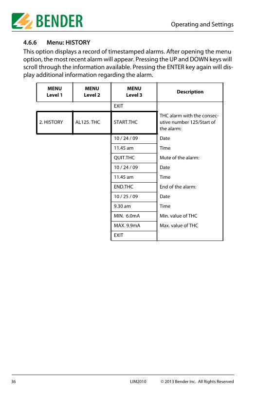
4.6.6 Menu: HISTORYThis option displays a record of timestamped alarms. After opening the menu option, the most recent alarm will appear. Pressing the UP and DOWN keys will scroll through the information available. Pressing the ENTER key again will dis-play additional information regarding the alarm.
MENULevel 1
MENULevel 2
MENULevel 3
Description
EXIT
2. HISTORY AL125. THC START.THCTHC alarm with the consec-utive number 125/Start of the alarm:
10 / 24 / 09 Date
11.45 am Time
QUIT.THC Mute of the alarm:
10 / 24 / 09 Date
11.45 am Time
END.THC End of the alarm:
10 / 25 / 09 Date
9.30 am Time
MIN. 6.0mA Min. value of THC
MAX. 9.9mA Max. value of THC
EXIT
36 LIM2010 © 2013 Bender Inc. All Rights Reserved
Operating and Settings
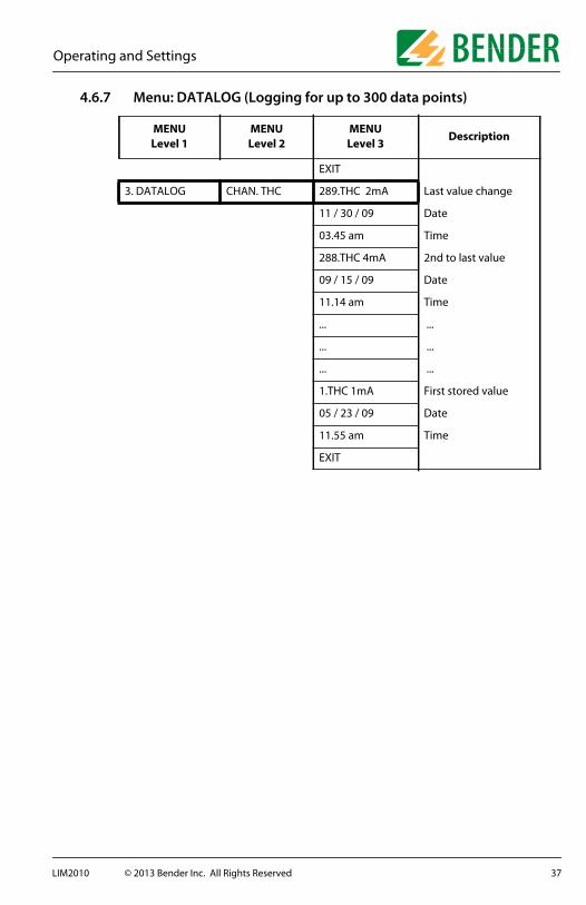
4.6.7 Menu: DATALOG (Logging for up to 300 data points)
MENULevel 1
MENULevel 2
MENULevel 3
Description
EXIT
3. DATALOG CHAN. THC 289.THC 2mA Last value change
11 / 30 / 09 Date
03.45 am Time
288.THC 4mA 2nd to last value
09 / 15 / 09 Date
11.14 am Time
... ...
... ...
... ...
1.THC 1mA First stored value
05 / 23 / 09 Date
11.55 am Time
EXIT
37LIM2010 © 2013 Bender Inc. All Rights Reserved
Operating and Settings
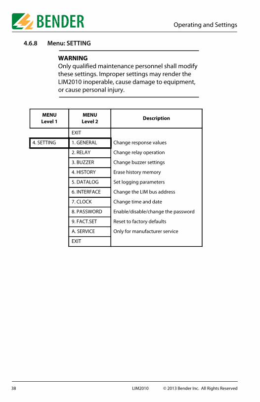
4.6.8 Menu: SETTING
MENULevel 1
MENULevel 2
Description
EXIT
4. SETTING 1. GENERAL Change response values
2. RELAY Change relay operation
3. BUZZER Change buzzer settings
4. HISTORY Erase history memory
5. DATALOG Set logging parameters
6. INTERFACE Change the LIM bus address
7. CLOCK Change time and date
8. PASSWORD Enable/disable/change the password
9. FACT.SET Reset to factory defaults
A. SERVICE Only for manufacturer service
EXIT
WARNINGOnly qualified maintenance personnel shall modify these settings. Improper settings may render the LIM2010 inoperable, cause damage to equipment, or cause personal injury.
38 LIM2010 © 2013 Bender Inc. All Rights Reserved
Operating and Settings
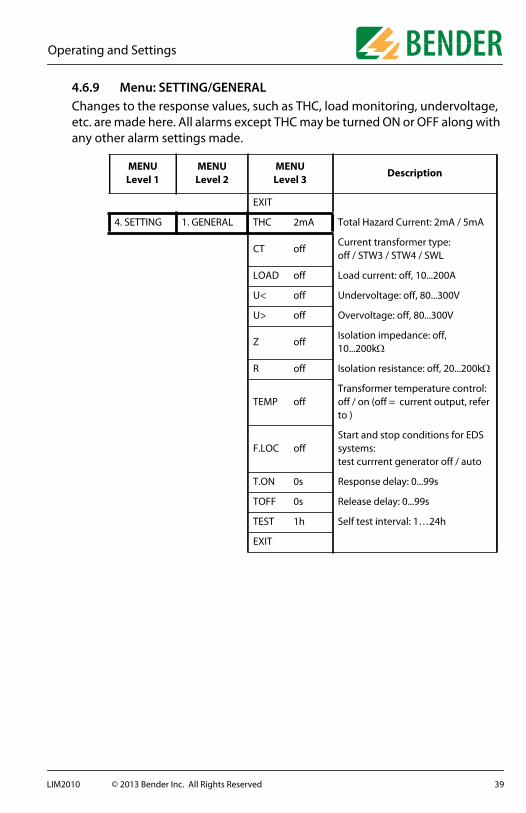
4.6.9 Menu: SETTING/GENERALChanges to the response values, such as THC, load monitoring, undervoltage, etc. are made here. All alarms except THC may be turned ON or OFF along with any other alarm settings made.
MENULevel 1
MENULevel 2
MENULevel 3
Description
EXIT
4. SETTING 1. GENERAL THC 2mA Total Hazard Current: 2mA / 5mA
CT offCurrent transformer type: off / STW3 / STW4 / SWL
LOAD off Load current: off, 10...200A
U< off Undervoltage: off, 80...300V
U> off Overvoltage: off, 80...300V
Z offIsolation impedance: off, 10...200k
R off Isolation resistance: off, 20...200k
TEMP offTransformer temperature control:off / on (off = current output, refer to )
F.LOC offStart and stop conditions for EDS systems: test currrent generator off / auto
T.ON 0s Response delay: 0...99s
TOFF 0s Release delay: 0...99s
TEST 1h Self test interval: 1…24h
EXIT
39LIM2010 © 2013 Bender Inc. All Rights Reserved
Operating and Settings
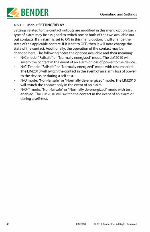
4.6.10 Menu: SETTING/RELAYSettings related to the contact outputs are modified in this menu option. Each type of alarm may be assigned to switch one or both of the two available out-put contacts. If an alarm is set to ON in this menu option, it will change the state of the applcable contact. If it is set to OFF, then it will note change the state of the contact. Additionally, the operation of the contact may be changed here. The following notes the options available and their meaning:• N/C mode: “Failsafe” or “Normally energized” mode. The LIM2010 will
switch the contact in the event of an alarm or loss of power to the device.• N/C-T mode: “Failsafe” or “Normally energized” mode with test enabled.
The LIM2010 will switch the contact in the event of an alarm, loss of power to the device, or during a self-test.
• N/O mode: “Non-failsafe” or “Normally de-energized” mode. The LIM2010 will switch the contact only in the event of an alarm.
• N/O-T mode: “Non-failsafe” or “Normally de-energized” mode with test enabled. The LIM2010 will switch the contact in the event of an alarm or during a self-test.
40 LIM2010 © 2013 Bender Inc. All Rights Reserved
Operating and Settings
MENULevel 1
MENULevel 2
MENULevel 3
MENULevel 4
Description
EXIT
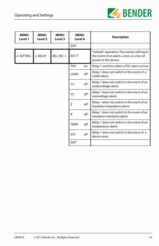
4. SETTING 2. RELAY REL. NO. 1 N/C-T"Failsafe" operation: The contact will trip in the event of an alarm, a test, or a loss of power to the device.
THC on Relay 1 switches when a THC alarm occurs
LOAD offRelay 1 does not switch in the event of a LOAD alarm
U< offRelay 1 does not switch in the event of an undervoltage alarm
U> offRelay 1 does not switch in the event of an overvoltage alarm
Z offRelay 1 does not switch in the event of an insulation impedance alarm
R offRelay 1 does not switch in the event of an insulation resistance alarm
TEMP offRelay 1 does not switch in the event of an temperature alarm
SYS offRelay 1 does not switch in the event of a device error
EXIT
41LIM2010 © 2013 Bender Inc. All Rights Reserved

Operating and Settings
4.6.11 Menu: SETTING/BUZZERSettings here relate to the audible alarm buzzer. If a type of alarm is set to ON, it will activate the audible alarm in the event of an alarm. If it is set to OFF, it will not activate the audible alarm.
4.6.12 Menu: SETTING/HISTORYSelecting YES will erase the history of alarms on the device. Once it is erased, the history cannot be recovered.
MENULevel 1
MENULevel 2
MENULevel 3
Description
EXIT
4. SETTING 3. BUZZER VOL HI Buzzer volume: High or Low
SY.MU on System mute: on/off
LOAD onBuzzer sounds in the event of an LOAD alarm
U< onBuzzer sounds in the event of an under-voltage alarm
U> onBuzzer sounds in the event of an over-voltage alarm
Z onBuzzer sounds in the event of an insula-tion impedance alarm
R onBuzzer sounds in the event of an insula-tion resistance alarm
TEMP onBuzzer sounds in the event of an temper-ature alarm
SYS onBuzzer sounds in the event of an device error
EXIT
MENULevel 1
MENULevel 2
MENULevel 3
MENULevel 4
Description
EXIT
4. SETTING 4. HISTORY DELETE DEL. noErase history memory: yes or no
EXIT
42 LIM2010 © 2013 Bender Inc. All Rights Reserved
Operating and Settings
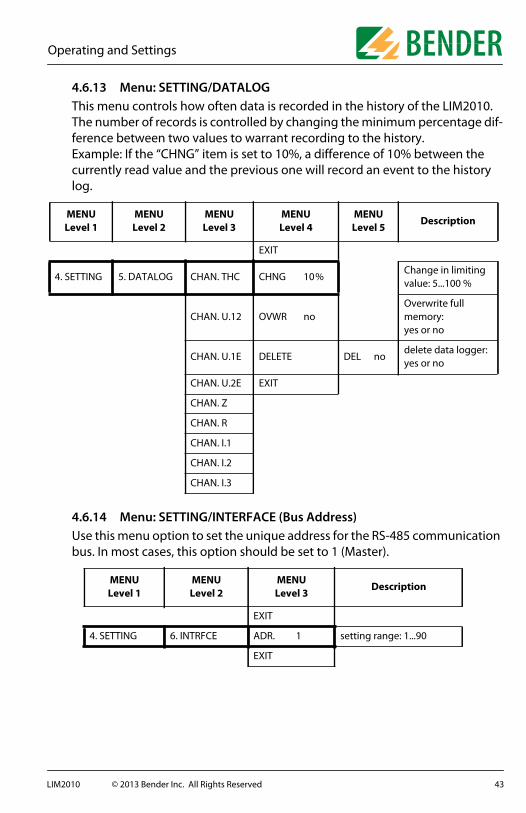
4.6.13 Menu: SETTING/DATALOGThis menu controls how often data is recorded in the history of the LIM2010. The number of records is controlled by changing the minimum percentage dif-ference between two values to warrant recording to the history.Example: If the “CHNG” item is set to 10%, a difference of 10% between the currently read value and the previous one will record an event to the history log.
4.6.14 Menu: SETTING/INTERFACE (Bus Address)Use this menu option to set the unique address for the RS-485 communication bus. In most cases, this option should be set to 1 (Master).
MENULevel 1
MENULevel 2
MENULevel 3
MENULevel 4
MENULevel 5
Description
EXIT
4. SETTING 5. DATALOG CHAN. THC CHNG 10 %Change in limiting value: 5...100 %
CHAN. U.12 OVWR noOverwrite full memory:yes or no
CHAN. U.1E DELETE DEL nodelete data logger:yes or no
CHAN. U.2E EXIT
CHAN. Z
CHAN. R
CHAN. I.1
CHAN. I.2
CHAN. I.3
MENULevel 1
MENULevel 2
MENULevel 3
Description
EXIT
4. SETTING 6. INTRFCE ADR. 1 setting range: 1...90
EXIT
43LIM2010 © 2013 Bender Inc. All Rights Reserved

Operating and Settings
4.6.15 Menu: SETTING/CLOCKSettings here relate to the time and date. If, upon powering the LIM2010 for the first time, a BATTERY LOW error appears, setting the date and time here and allowing the device to run in normal operation will clear the error.
4.6.16 Menu: SETTING/PASSWORD
4.6.17 Menu: SETTING/FACTORY SETTINGThis menu option will reset the device to factory defaults. Once reset, it cannot be restored to its previous state automatically. Any changes must be re-entered.
MENULevel 1
MENULevel 2
MENULevel 3
Description
EXIT
4. SETTING 7. Clock Tm 10.34A Time: am/pm
Dy 12/23 Date: month/day
Yr 2009 Year
DST autoDaylight saving time: auto/off(North America time zones only)
EXIT
MENULevel 1
MENULevel 2
MENULevel 3
Description
EXIT
4. SETTING 8. PASSWRD PSWD ***Password range: 000...999Factory setting 807
LOCK offPassword protection activated (on) or deactivated (off)
EXIT
MENULevel 1
MENULevel 2
MENULevel 3
Description
4. SETTING 9. FACT.SET F.SET no Factory setting deactivated
F.SET yes Factory setting will be restored
44 LIM2010 © 2013 Bender Inc. All Rights Reserved

Operating and Settings
4.6.18 Menu: SETTING/SERVICEThis menu is for manufacturer service only.
4.6.19 Menu: CONTROL/TESTSetting this menu option to “yes” will allow connected remote indicators with bus capability to initiate a self-test on the LIM2010 when the TEST button is pressed on the respective remote indicator.
4.6.20 Menu: CONTROL/COMMUNICATION TESTThis menu option enables testing of the RS-485 communication bus between the LIM2010 and other bus-compatible devices.
MENULevel 1
MENULevel 2
MENULevel 3
Description
5. CONTROL 1. TEST TEST no test deactivated
TEST yes Test will be activated
MENULevel 1
MENULevel 2
MENULevel 3
Description
EXIT
5. CONTROL 2. COM.TEST 1.THCSending THC alarm message via BMS bus
2.LOADSending overload alarm mes-sage via BMS bus
3.U.12Sending overvoltage alarm message via BMS bus
6.ZSending low impedance alarm message via BMS bus
7.RSending low resistance alarm message via BMS bus
9.TEMPSending overtemperature alarm message via BMS bus
11.SYSSending system fault alarm message via BMS bus
EXIT
45LIM2010 © 2013 Bender Inc. All Rights Reserved
Operating and Settings
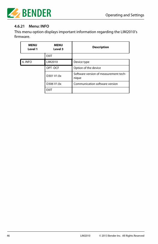
4.6.21 Menu: INFOThis menu option displays important information regarding the LIM2010’s firmware.
MENULevel 1
MENULevel 3
Description
EXIT
6. INFO LIM2010 Device type
OPT -DCF Option of the device
D301 V1.0xSoftware version of measurement tech-nique
D306 V1.0x Communication software version
EXIT
46 LIM2010 © 2013 Bender Inc. All Rights Reserved

Periodic Testing
5. Periodic TestingBENDER recommends regular testing of the LIM2010 and the isolated power system it protects. Consult the manufacturer or a local representative for more information.
Additionally, BENDER recommends pressing the TEST button on the LIM2010 at least monthly to ensure proper operation of the Line Isolation Monitor.
47LIM2010 © 2013 Bender Inc. All Rights Reserved

Messages from the RS-485 Bus
6. Messages from the RS-485 Bus
6. 1 Alarm Messages
Alarm messages are created when one or more of the alarms activate. Depending on the type of device, these may be alarm values, a device’s status, or an error message. These messages are controlled by the device in the sys-tem designated as the master. For details about error codes, refer to section 7.4.
Channel Description
111
Total hazard current, in mABad ground connectionBad system connection
222
Transformer overload, in %Short circuit at CT connectionBad CT connection
33
Undervoltage between L1 and L2, in VOvervoltage between L1 and L2, in V
6 Impedance ZF in k
7 Resistance RF in k
9 Transformer overtemperature
10 Ground fault location in operation
11 Internal device error
48 LIM2010 © 2013 Bender Inc. All Rights Reserved
Messages from the RS-485 Bus
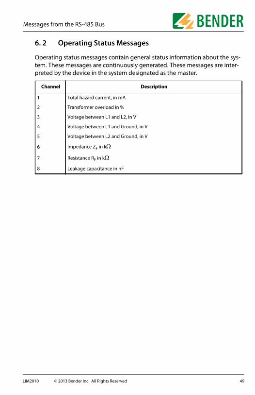
6. 2 Operating Status Messages
Operating status messages contain general status information about the sys-tem. These messages are continuously generated. These messages are inter-preted by the device in the system designated as the master.
Channel Description
1 Total hazard current, in mA
2 Transformer overload in %
3 Voltage between L1 and L2, in V
4 Voltage between L1 and Ground, in V
5 Voltage between L2 and Ground, in V
6 Impedance ZF in k
7 Resistance RF in k
8 Leakage capacitance in nF
49LIM2010 © 2013 Bender Inc. All Rights Reserved
Technical Data
7. Technical Data
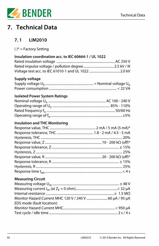
7. 1 LIM2010
( )* = Factory Setting
Insulation coordination acc. to IEC 60664-1 / UL 1022Rated insulation voltage ...................................................................... AC 250 VRated impulse voltage / pollution degree.....................................2.5 kV / IIIVoltage test acc. to IEC 61010-1 and UL 1022 ..................................... 2.0 kV
Supply voltageSupply voltage US.......................................................... = Nominal voltage UnPower consumption ................................................................................. < 22 VA
Isolated Power System RatingsNominal voltage Un ..................................................................... AC 100 - 240 VOperating range of Un ..................................................................... 85% - 110%Rated frequency fn .................................................................................. 50/60 HzOperating range of fn ......................................................................................±5%
Insulation and THC MonitoringResponse value, THC ....................................................... 2 mA / 5 mA (5 mA)*Response tolerance, THC ............................................ 1.8 - 2 mA / 4.5 - 5 mAHysteresis, THC .................................................................................................. 20%Response value, Z .................................................................... 10 - 200 kΩ (off)*Response tolerance, Z ................................................................................. ± 15%Hysteresis, Z ........................................................................................................ 25%Response value, R .................................................................... 20 - 200 kΩ (off)*Response tolerance, R ................................................................................. ± 15%Hysteresis, R ........................................................................................................ 25%Response time tan.............................................................................................< 4 s
Measuring CircuitMeasuring voltage Um ................................................................................ ± 48 VMeasuring current Im (at ZF = 0 ohm)..................................................< 32 μAInternal resistance ..................................................................................≥ 1.5 MΩMonitor Hazard Current MHC 120 V / 240 V ......................... 60 μA / 95 μAEDS mode (fault location):Monitor Hazard Current MHC.............................................................. < 950 μATest cycle / idle time .................................................................................. 2 s / 4 s
50 LIM2010 © 2013 Bender Inc. All Rights Reserved

Technical Data
Voltage MonitoringResponse value, under/overvoltage (<U / >U).................80 - 300 V (off)*Response tolerance .........................................................................................± 3%Hysteresis .............................................................................................................. 4 %
Load Current (Transformer Overload) MonitoringResponse value ............................................................................10 - 200 A (off)*Response tolerance .........................................................................................± 5%Hysteresis .............................................................................................................. 4 %
Temperature MonitoringResponse value ..................................................................................................4 kΩRelease value .................................................................................................. 1.6 kΩPTC resistor acc. to DIN 44081..........................max. 6 connected in series
Adjustable Time Delays (Do NOT Apply to THC Alarm)Response delay ton ...........................................................................0 - 99 s (0 s)*Delay on release toff .........................................................................0 - 99 s (0 s)*
Displays, Memory14-segment display...................................................8 digits, multifunctionalDisplayed measured value, THC ................................................... 0.0 - 9.9 mAOperating uncertainty, THC ...................................................± 7% / ± 0.1 mAMeasured value, load current (as % of response value)...........10 - 199%Operating uncertainty, load current ........................................±5% / ± 0.2 AMeasured value, line voltage............................................................. 10 - 300 VOperating uncertainty, line voltage ............................................± 5% / ± 2 VMeasured value, impedance Z ....................................................... 0 - 1000 kΩOperating uncertainty, impedance Z ......................................± 5% / ± 1 kΩMeasured value, resistance R.......................................................... 2 - 1000 kΩOperating uncertainty, Z ~ R.................................................... ± 20% / ± 1 kΩMeasured value, leakage capacitance C ........................................ 0 - 500 nFOperating uncertainty, Z ~ XC ..................................................± 20% / ± 5 nF(No indication of R and C at Z < 2 kΩ)Measured value, load current ...........................................................0.5 - 250 AOperating uncertainty, load current .........................................± 5%, ± 0.2 A7-segment display .........................................2 digits, digital THC indicationBar graph indicator....................................................... analog THC indicationHistory memory ......................................................................300 event recordsData logger................................................................................. 300 data records
51LIM2010 © 2013 Bender Inc. All Rights Reserved

Technical Data
Inputs / OutputsAnalog current output M+/M- ..........................................................0 - 400 μAOperating uncertainty ................................................................................ ± 10%Output RI1, 12VDC COM.............................................................. 12 V / 200 mARI2, SAFE, HAZARD, TEST.......................................max. qty. 4 MK2000(C)(P)Cable length ..............................................................................max. 32 ft (10 m)
RS-485 InterfaceInterface A-B / Protocol....................................... RS-485 / BMS (proprietary)Baud rate..................................................................................................9600 baudMax. cable length without repeater................................... 3900 ft (1200 m)Recommended cable(Shielded, twisted pair, 1 end grounded) .............................. J-Y(St)Y 2x0.8Termination resistor...............120 Ω (0.25 W), DIP switch activated (off)*Device address, BMS bus......................................................................1 - 90 (1)*
Switching ElementsQuantity.........................................................................................2 SPDT contactsOperating principle............. Normally energized or de-energized (N/E)*Electrical endurance .......................................................................10,000 cyclesContact data acc. to IEC 60947-5-1:Relay 1:Utilization Category .....................AC-13 AC-14 DC-12 DC-12 DC-12Rated operational voltage.......... 230 V 230 V 24 V 110 V 220 VRated operational current .............5A 3A 1 A 0.2 A 0.1 AMinimum contact rating ..............................................1 mA at AC/DC ≥ 10 VRelay 2:Utilization Category .............................DC-12 DC-12 DC-12 DC-12Rated operational voltage................. 250 V 24 V 110V 220 VRated operational current ....................2 A 1.2 A 0.4 A 0.25 A Minimum contact rating ..............................................1 mA at AC/DC ≥ 10 V
Environment / EMCEMC ............................................................................................................. IEC 61326Operating temperature ................................. +14 F - +122 F (-10 C - +50 C)Storage temperature ......................................-13 F - +158 F (-25 C - + 70 C)Climatic class acc. to IEC 60721:Stationary use (IEC 60721-3-3) ...............................................................3K5 (**)Transport (IEC 60721-3-2) ........................................................................2K3 (**)Long-term storage (IEC 60721-3-1) ......................................................1K4 (**)** = Except condensation and formation of ice
52 LIM2010 © 2013 Bender Inc. All Rights Reserved

Technical Data
Classification of mechanical conditions acc. to IEC 60721:Stationary use (IEC 60721-3-3) .....................................................................3M4Transport (IEC 60721-3-2) ..............................................................................2M2Long-term storage (IEC 60721-3-1) ............................................................1M3
ConnectionConnection type.....................................................................Molex plug, qty. 2....................................................................................... 15-pole, type 03-09-2159...................................................................................... 12-pole, type 43045-1215
General DataOperating mode ................................................................................. ContinuousMounting position................................................................... Display-orientedDegree of protection, internal components ...................... NEMA 1 (IP 30)Enclosure material ........................................................................PolycarbonateFlammability class....................................................................................UL94 V-0Type of enclosure...........................................Enclosure for panel mountingScrew fixing...........................Qty. 4 #4-40 truss head black oxide finishedTightening Torque.............................................. 2.6 - 3.5 lb-in (0.3 - 0.4 N-m)Firmware version.......................................................D301 V1.0x / D306 V1.0xWeight........................................................................................ app. 1.2 lb (550 g)
53LIM2010 © 2013 Bender Inc. All Rights Reserved

Technical Data
7. 2 Connector Plate
CP-LIM2010Cable length ..................................................................................... 20” (508 mm)Terminal strip ..................................................................................... 22 terminalsConnector....................................................... 15 pin Molex and 12 pin MolexConductor size ................................................................................... AWG 22 - 12Screw fixing.......................2-32 x1/2 slotted oval head machine screw SSTightening torque .....................................................................8 lb-in (0.9 N-m)Mounting orientation....................................................................................... AnyWeight .......................................................................................... app. 7 oz (200 g)
7. 3 Current Transformers
7.3.1 Technical Data: STW3Rated voltage Um..................................................................................... AC 720 VRated impulse voltage Uisol............................................................................4 kV
Measuring CircuitRated transformation ratio kn...........................................................100 / 0.1 ARated burden................................................................................................... 200 ΩMaximum rated primary current...............................................................100 AMinimum rated primary current ....................................................................1 ANominal power ..................................................................................................2 VANominal frequency..............................................................................50 - 400 HzInternal resistance ............................................................................................17 ΩAccuracy class ...........................................................................................................1Rated thermal current, continuous ..........................................................120 ARated thermal current, 1 s ........................................................................ 1000 ADynamic rated current, 30 s ..................................................................... 2500 A
54 LIM2010 © 2013 Bender Inc. All Rights Reserved

Technical Data
7.3.2 Technical Data: STW4Rated voltage Um .....................................................................................AC 720 VRated impulse voltage Uisol ........................................................................... 4 kV
Measuring CircuitRated transformation ratio kn...........................................................200 / 0.1 ARated burden...................................................................................................200 ΩMaximum rated primary current .............................................................. 200 AMinimum rated primary current.................................................................... 2 ANominal power ..................................................................................................2 VANominal frequency..............................................................................50 - 400 HzInternal resistance............................................................................................ 40 ΩAccuracy class........................................................................................................... 1Rated thermal current, continuous ......................................................... 240 ARated thermal current, 1 s.........................................................................2000 ADynamic rated current, 30 s .....................................................................5000 A
7.3.3 General Data: STW3 / STW4Standard ................................................................................................ IEC 60044-1Shock resistance acc. to IEC 60068-2-27 (built-in)................. 15 g / 11 msBumping, IEC 60068-2-29 (during transport).............................40 g / 6 msVibration resistance, IEC 60068-2-6 (built-in)...................1 g / 10 - 150 HzOperating temperature ..................................... +32 F - +185 F (0 C - +85 C)Storage temperature ....................................... -40 F - +185 F (-40 C - +85 C)Climate category acc. to DIN IEC 60721-3-3 ............................................. 3K5Operating mode ............................................................... Continous operationPosition ................................................................................................ Any positionScrew mounting .................................................................................................. M3Flammability class....................................................................................UL 94V-0
Connection TypeConnection................................................................Faston plug, 6.3 x 0.8 mmSingle wires ≥ AWG 18 (0.7 mm2).................................................................................................................... 3.2 ft (1 m)Single wires, twisted ≥ AWG 18 (0.7 mm2)...................................................................................................................32 ft (10 m)Screened cable ≥ AWG 20 (0.6 mm2), 1 end grounded ................................................................................................................ 132 ft (40 m)
55LIM2010 © 2013 Bender Inc. All Rights Reserved

Technical Data
7. 4 Error Codes and Troubleshooting
Error Code Description and Action
ERROR 0.10
BAD CT CONNECTIONInterruption in the connection of the load monitoring current transformer.Action: Check the connection of the current transformer to the connector plate. NOTE: The SWL-100A does not activate this alarm. Ensure proper connections if this device is used.The error will automatically clear itself when the issue is resolved.
ERROR 0.20
CT SHORT CIRCUITA short circuit is present at the current transformer.Action: Check the current transformer for possible short circuit.The error will automatically clear itself when the issue is resolved.
ERROR 0.30
BAD GROUND CONNECTIONBad connection on LIM GND/GND2 ground loopAction: Ensure that both LIMGND and GND2 connections are not interrupted and properly tied to ground.The error will automatically clear itself when the issue is resolved.
ERROR 0.40
BAD SYSTEM CONNECTIONIndicates that the system voltage does not fall within the threshold required by the LIM2010 and that one of the following has occured:- < 85 V, > 265 V- Nominal frequency outside 50/60 Hz rangeAction: Ensure that the system voltage and frequency of the sys-tem fall within the limits of the LIM2010.The error will automatically clear itself when the issue is resolved.
ERROR 2.10
NO MASTERNo BMS (RS-485 communication) master exists. Even if RS-485 communication is not utilized, the LIM2010 must be assigned an address of 1.Action: If the LIM2010 is connected to a BMS network, ensure that one device on the network is set to address 1. Otherwise, set the LIM2010 to address 1.The error will automatically clear itself when the issue is resolved.
ERROR 2.20
RS-485 ERRORBMS bus error.Action: Ensure that there are no conflicting address settings on the RS-485 bus. Check RS-485 wiring.The error will automatically clear itself when the issue is resolved.
56 LIM2010 © 2013 Bender Inc. All Rights Reserved

Technical Data
7. 5 Dimensions: STW3 / STW4
Dimensions in inches (mm)
Error 8.80
BATTERY LOWThe battery backup for the built-in clock is discharged. This error may occur when first installing the device.Action: Enter the main menu. Check the time and date settings, and reset them if required. The battery will then recharge during normal operation.The error will automatically clear itself when the issue is resolved.
All other errors Action: Contact the manufacturer.
Error Code Description and Action
1.25”(32)
0.62
5”(1
6)
M3
2” (5
0)
2” (5
0)
2” (50)1.55”(40)
1.25
”(3
2)
0.7” (18)
0.25”(6.35)
2” (50)
57LIM2010 © 2013 Bender Inc. All Rights Reserved

Technical Data
7. 6 Ordering Information
Type Description Approval Ordering No.
LIM2010 Line Isolation Monitor UL Listed B 9207 5021
CP-LIM2010 LIM Connector PlateUL
RecognizedB 5111 00001
Remote Indicators
MK2000-G1MuteSingle gang plate
UL Listed B 5213 00002
MK2000-G2MuteTwo-gang plate
UL Listed B 5213 00007
MK2000P-G1Mute + TestSingle gang plate
UL Listed B 5213 00188
MK2000C-G1Mute + OverloadSingle gang plate
UL Listed B 5213 00020
MK2000CP-G1Mute + Test + OverloadSingle gang plate
UL Listed B 5213 00021
MK2000CBMMute + Test + OverloadDigital MeteringTwo-gang plate
UL Listed B 5313 00022
Load Monitoring Current Transformers
STW3 Up to 100 A load currentUL
RecognizedB 9802 1000
STW4 Up to 200 A load currentUL
RecognizedB 9802 1001
LIM Testers
LT3000 Kit Tester Only - B 5213 00004
LT3000 SetTester + Carrying Case +Adapter for 2300HG receptacle
- B 5213 00295
58 LIM2010 © 2013 Bender Inc. All Rights Reserved


T M
Bender Inc.
USA:700 Fox ChaseCoatesville, PA 19320Toll Free: 800-356-4266Phone: 610-383-9200Fax: 610-466-2071E-mail: [email protected]
Canada:5810 Ambler Drive, Unit 1Mississauga, ON L4W 4J5Toll Free: 800-243-2438Phone: 905-602-9990Fax: 905-602-9960E-mail: [email protected]
Web: www.bender.org


![nenomatica · 2018. 8. 15. · v) lim f(x) lim f(x) —2 limf(x)] 1 = 2 l, liml:rl lim xl=O lim I ae IR (u ( —21 = —4 — a L. Jlþy=x a lim x—sa www_ n . lim f (x) = — lim](https://img.pdfslide.net/doc/110x75/60da74b2850abc389e16bf7e/nenomatica-2018-8-15-v-lim-fx-lim-fx-a2-limfx-1-2-l-limlrl-lim.jpg)