Embed Size (px)
Citation preview

GEF-4630ALimitamp® Medium-Voltage Motor Control

Limitamp® Medium Voltage Motor Control
Table of Contents
Introduction 2
Parts Identification 2
High-Voltage Contactor Nameplate
Limitamp® Panel Data Nameplate .
Catalog Numbering
One-High Construction
Two-High Construction
Three-High Construction
2
3
3
4, 5
6, 7
8, 9
Handle Assembly 10
Bus Assemblies 11, 12
Fuse Support Assemblies (Control Power Transformer) 13
Stab & Track Assemblies 13
Warning: Before any adjustments, servicing, parts replacement or any other act is performed requiring physical contact with theelectrical working components or wiring of this equipment, all power must be removed and locked off from all sources and all attachedrotating equipment must have come to a complete stop. User personnel must be completely familiar with the following operating andmaintenance instructions before attempting to service this equipment.
1
IntroductionThe CR7160 Limitamp® Controller, a quality GE product,was designed and manufactured to give long and satisfactoryservice. This bulletin contains items that, through normal use,may require periodic replacement; other items may neverneed service or replacement during the useful life of theequipment.
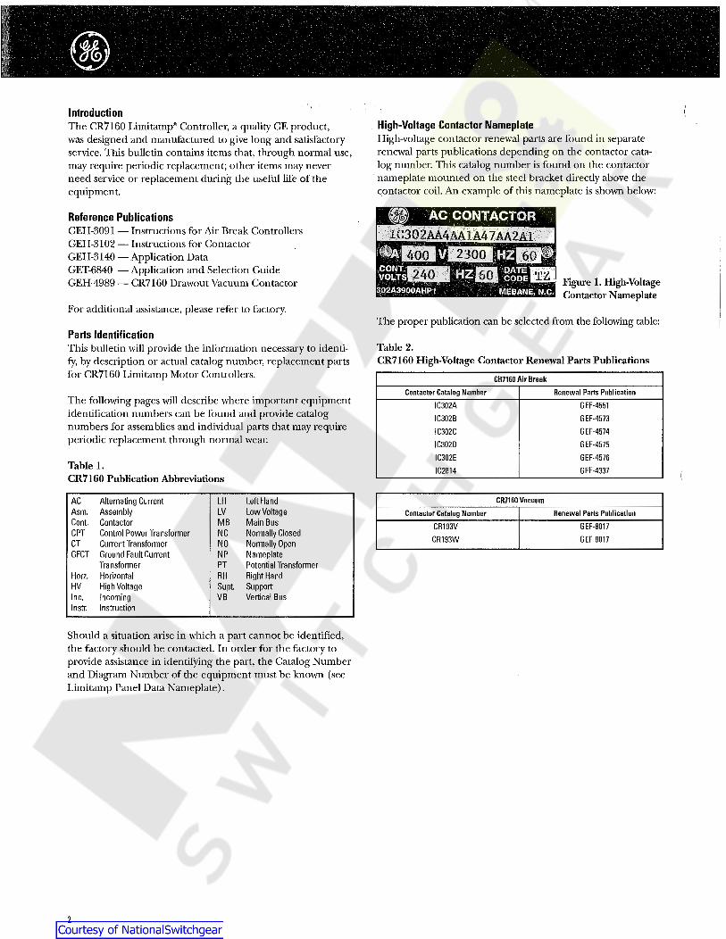
High-Voltage Contactor NameplateHigh-voltage contactor renewal parts are found in separaterenewal parts publications depending on the contactor cata-log number. This catalog number is found on the contactornameplate mounted on the steel bracket directly above thecontactor coil. An example of this nameplate is shown below:
m AC CONTACTORReference PublicationsGEH-3091 — Instructions for Air Break ControllersGEH-3102 — Instructions for ContactorGEH-3140 — Application DataGET-6840 — Application and Selecdon GuideGEH-4989 — CR7160 Drawout Vacuum Contactor
IC302AA4AA1A47AA2A1400IH 2300IT
60 HiHi
6013240 TZt ] » Figure 1. High-VoltageContactor Nameplate» Jiiiiji’
For additional assistance, please refer to factory.The proper publication can be selected horn the following table:
Parts IdentificationThis bulletin will provide the information necessary to identi-fy, by description or actual catalog number, replacement partsfor CR7160 Limitamp Motor Controllers.
Table 2.CR7160 High-Voltage Contactor Renewal Parts Publications
CR7160 Air BreakRenewal Parts PublicationContactor Catalog Number
The following pages wall describe wTiere important equipmentidentification numbers can be found and provide catalognumbers for assemblies and individual parts that may requireperiodic replacement through normal wear.
IC302AIC302BIC302CIC302DIC302EIC2814
GEF-4551GEF-4573GEF-4574GEF-4575
GEF-4576
GEF-4337Table 1.CR7160 Publication Abbreviations
CR7160 VacuumAC Alternating CurrentAsm. AssemblyCont. ContactorCPT Control Power TransformerCT Current TransformerGFCT Ground Fault Current
TransformerHorz. HorizontalHV High VoltageInc. IncomingInstr. Instruction
LH Left HandLV Low VoltageMB Main BusNC Normally ClosedNO Normally OpenNP NameplatePT Potential TransformerRH Right HandSupt. SupportVB Vertical Bus
Contactor Catalog Number Renewal Parts PublicationCR193VCR193W
GEF-8017GEF-8017
Should a situation arise in which a part cannot be identified,the factory should be contacted. In order for the factory toprovide assistance in identifying the part, the Catalog Numberand Diagram Number of the equipment must be known (seeLimitamp Panel Data Nameplate) .
2

Limitamp® Medium Voltage Motor Control
Limitamp Panel Data NameplateThis nameplate is mounted near the starter handle operatoron the high-voltage door. It contains all the necessary infor-mation for the factory to positively identify the starter and itsbill of material. This information must accompany all partorders and quotation requests. An example of this nameplateis shown below:
Catalog Numbering SystemLimitamp control is manufactured in three constructiontypes: one-high, two-high and three-high. One-high construc-tion consists of one medium-voltage contactor in one 90-inch-high enclosure. Two-high construction contains two medium-voltage contactors in one 90-inch-high enclosure. Three-highconstruction has three medium-voltage contactors in one 90-inch-high enclosure.
You should first determine the construction type (one-high,two-high or three-high) of your equipment. After determina-tion, the following pages should be consulted:
Pages 4 and 5 for one-high constructionPages 6 and 7 for two-high constructionPages 8 and 9 for three-high construction
CAT. 0607X0431V02-A01MODELMODELEDIAGRAM 221B3466SCHEMAPOWER FUSE CAT. NO.FUSIBLE DE PUIS., N°CAT.INTERRUPTING RATINGPOUVOIR DE COUPURE
3 PHASE 60 HZ 4000 VOLTS AC_VOLTS C.A.
218A4291P6RB
360 MVA CLASS E J_MVA CLASSE E Caution should be observed in that a part number in one-
high construction may have a different description and cata-log number than the same part number in two- or three-highconstruction.
KV BILKV TTC
RMS AMPERES 40°C AMB.EFF., A,4Q°C AMBIANTE_RMS AMPERES
EFF., AMPERESRMS AMPERESEFF, AMPERES
CONT. CUR. RATINGCOUR..SERVICE CONT.SERVICE LIMIT CUR. RATtNG_COURANT LIMITE EN SERVICEHORIZ. BUS CUR. RATING _COUR. NOM., BUS HORIZONCONTROL CIRCUIT 116CIRC. DE COMMANDEPOWER CIRCUIT MAX. VOLTS .CIRCUIT DE PUISSANCE, MAX.
Another method of identifying construction is through thecontroller “CR” number (shown on the panel data name-plate) . Example: Catalog Number 7160A118G. The alphasuffix determines one-high, tiuo-high or three-high; G is one-high,K is two-high and H is three-high. Vacuum starters are designatedby an M suffix. Example: Catalog Number 7160A118GM .
VOLTSv
ACv C.A.
LOAD: TYPECHARGE: TYPE
.FULL LOAD CUR.COUR.PLEINE CH.
V ACV C.A.AMR 08 P.F.
AMP.A
W.R. MOTOR SECMOTEUR SECOND., ROTOR BOB.SYNC. FIELD_CHAMP SYNC.
AMP.A
V DCVCC F.RA This “CR” number is further referenced in GEH-3091.
CAUTION BEFORE INSTALLING OR OPERATING READ INSTRUCTIONS.
ATTENTION. LIRE LES INSTRUCTIONS AVANT DE PR0CEDER A L'INSTALLATION.GEH-3091.GFH-310?
DO NOT OPERATE STARTERS FURNISHE0 WITH CURRENT TRANSFORMERSUNLESS RELAY ELEMENTS ARE INSTALLED.NE PAS UTILISER LES DEMARREURS F0URNIS AVEC LES TRANSFORMATEURSDE COURANT AVANT OUE LES RELAIS S0IENT INSTALLES.
Figure 2. Limitamp Panel Data Nameplate
The required information is the catalog number and thediagram number. The catalog number from the sample aboveis 0607X0431V02 A01. The number can be broken down asfollows: 0607X0431 is the material list number or shop ordernumber for the job, V02 is the overall lineup designation, andA01 is a section in that lineup. The diagram number identifiesthe group of drawings that pertain to this particular projectorder.
Sections that do not have a panel data nameplate will have acompartment nameplate mounted on the right side doorflange. An example is shown below:
Figure 3.LimitampCompartmentNameplate
This will provide the catalog number only. The diagramnumber can be obtained from any Panel Data Nameplate onthat lineup.
3
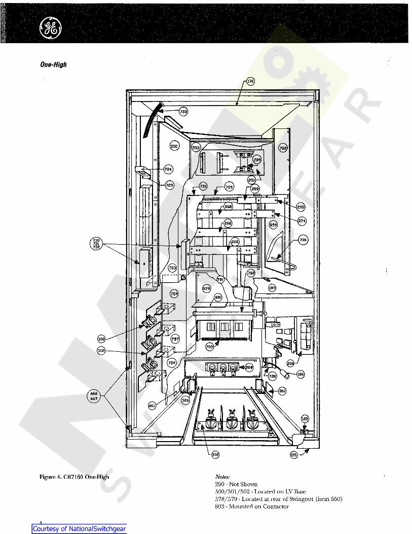
One-High
©©
Figure 4. CR7160 One-High Notes:290 - Not Shown500/501/502 - Located on LV Base578/579 - Located at rear of Swingout (item 550)803 - Mounted on Contactor
4

Limitamp Medium Voltage Motor Control
Table 3.CR7160 34” Wide One-High Drawout Air/Vacuum Parts List (See Figures 4 and 5)
MaterialList ItemNumber
Part Description Part Number Qty.Lintel
Lintel CatchWire Trough
Compartment Barrier Asm.Door Interlock Defeater
68J210552AM34XXXXB194A7164G1
68J222210CBOOOOAAB117B4515G6194A6916G1
115 1122 1170 1187 1194 1
CPT Primary Fuse Supt. Asm.Intermediate Stab Asm. w/o PTIntermediate Stab Asm. w/ PT
Handle Asm.CPT Mounting Base
55C682289G* O149B1743G6149B1743G5
116C9928G* ©68J210552AB34XXXXB
209 1212 1
1212218 1250 1
AC Bus CopperAC Splice Copper
Ground Bus
104B9369P* ©Consult factory104B9334P* ©232A9331P* ©
268 3©274 3
289 1 <§>Ground Bus Link-CopperGround Bus Splice-Copper
290 1Consult factory 1295 OWindow CT Supt.
Dummy CT PlateMotor Stab Asm.
Multilin GFCT Supt.2-1/2” Window GFCT Supt.
219A1229P1302 3394B686G11149B1743G4
68J122212VHOOOOAAB219A1229P1
308 3309 1
1326326 1
Test Switch 10A CR104PSG21B92328A1141P1328A1140P1
Included with item 500 (20A)68J122214NSOOOOAAB
1500Test Switch 20ASwitch NP 10ASwitch NP 20A
Test Switch Mounting Bracket
500 11501
501 1502 1
Swingout PanelLV Base
68J222222SMOOOOAAB68J120132BT0504AAB68J122220DTOOOOAAB68J122220DS0000AAB
550 1553 1
Swingout BarrierSwingout Barrier
LV Door
578 1579 1
Consult factory653 1Bottom Door
Door Latch Asm.Consult factory
104B9336G2656 1 Figure 5. CR7160 One-High Door Detail
3659Door Hinge Pin
Door HingeSwing Base Stop-Barrier
666 1459941P1147A4728G1
68J120125DLOOOOAAB
66667
722 1Wire Harness 7118R50G2V
128C6635P1128C6636P1
AMP# 350638-1AMP# 350639-1
1723Control Wire Plug-Bottom
Control Wire Plug-TopPlug Socket
Plug Pin
724 1724A 1724B 15724C 15724D Crimper Tool
Coil PlugWire Plug Supt.Wire Comb CleatWire Comb Cover
AMP# 90124-2169B7635G5219A1225P1171B4725P1171B4726P1
117281729
730 33731
Wire Comb Supt.Swingout Handle
AC Bus Barrier (Inc. Line)AC Bus Barrier (no Inc. Line)VB Barrier Asm. (Inc. Line)
219A1242P1104B9322P6149B1753G1149B1753G2149B1753G4
732 11736
750 11750
751 1VB Barrier Asm. (no Inc. Line)Lower Inc. Line Barrier Bottom
149B1753G3194A6985G1245A4374G3
68J120125MF0000AAB194A6968P2
1751752 1
Upper Inc. Line BarrierLower Inc. Line Barrier Upper
VB Barrier Bottom Cover
1753754 1
1755302A3732P1
68J120125MG0000AAB68J210553AJXXXXXXB
194A4480G* ©
Barrier ExtensionLower Inc. Line Barrier Center
AC Bus Barrier Upper ShelfShutter-Bus Asm.
Power Fuse
175617571759
762 1© 3803
68J120125BMOOOOAAB194A7197P5
68J120131ALOOOOAA B205A4475P2
Bus Cover PlateCable Cover Plate
PT BasePT Insulator
859 228611879
881 1
© See Table 19.© See Tables 6 and 7.© See Table 9.0 See Table 12.
© Add suffix (*) per plating finish:l=no plating, 2=Silver, 3-Tin.
© See Table 11.@ See panel data NP for fuse part number.
5
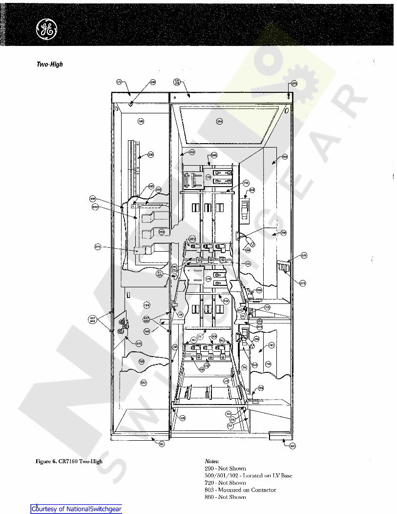
Two-High
v©
667668
161 162'
Figure 6. CR7160 Two-High Notes:290 - Not Shown500/501/502 - Located on LV Base720 - Not Shown803 - Mounted on Contactor860 - Not Shown
6

Table 4.CR7160 44” Wide Two-High Air/Vacuum Parts List (see Figures 6, 7 and 8)
MaterialList ItemNumber
MaterialList ItemNumber
Pert Description Part Number Qty.Part NumberPart Description Qty.Track & Barrier Asm.
Door Interlock Defeater UpperDoor Interlock Defeater Lower
Test Switch 10ATest Switch 20A
116C9939AAG2194A6916G1194A6916G4
CR104PSG21B92328A1141P1
1N529P63B6139B8564G3139B8564G4194A7383P1
68J220134FD0000AAB
310108 Plug ButtonLeft Track Supt.
Right Track Supt.Washer PlateVertical Lintel
11315115 11315116 11500129 611 500160
Switch NP 10ASwitch NP 20A
Test Switch Mounting BracketTerminal Board Supt.
LV Base
328A1140P1Included with item 500 (20A)
68J122214NS0000AAB194A7176P1
68J120125GL0000AAB
1Bottom LV LintelBottom HV Lintel
LV MullionDust Shield NEMA 1
Wire Trough
149B3258P168J120134JDOOOOAAB
174A8913G168J120125EUOOOOAAB68J220134FU0000AAB
501161 11501162 11502163 13164 1 50811 553170
LV Door Latch Asm.HV Door Latch Asm.
HV Door Vent Barrier NEMA 1Vent Cover NEMA 1A, 2, 12
LV Door
117B5064G3104B9336G2205A4475P2
68J120134EE0102AABConsult factory
Upper LV LintelUpper HV Lintel
Lintel Latch Screw Asm.RH Center Mullion
CPT Fuse Base Asm.
233A1836G168J120134FR0000AAB
174A7367G1259A1447G1
68J220134FH0000AAB
2171 1 63221 63517212173 6461646174 11653175 1
68J210551CMXXXXXXB68J210551CLXXXXXXB
147A4728G11459941P1
68J220134FS0000AAB
177B2069G1259A1452P1
68J122217EYOOOOAAB169B7635G5577A180P3
HV Door UpperHV Door Lower
Door HingeHinge Pin
Upper Motor Cable Barrier
1CT Supt. Asm.CT BarrierCT Supt.Coil Plug
HV Bushing
1 6561761 656 1180
6181 66761186 6681211 2 700
116C9928G* ©149B1741P1
116C9952G* ©Consult factory
157C8151G2
Inc. Line Barrier UpperInc. Line Barrier Lower
LV Base BarrierRH Rear Barrier UpperRH Rear Barrier Center
68J220134FK0000AAB68J120134FMOOOOAAB68J120125FR0000AAB
68J210553BAXXXXXXB68J120125FD0000AAB
1Handle Asm.Bus Insulation (Back Cover)
Horz. & VB Asm.Main Bus Splice
Motor Terminal Asm. Upper
1 7022181250 1 704
1 705 12681274 1 70711 708275
68J210553BBXXXXXXB194A6968P2
68J220134FYOOOOAAB68J220134FE0000AAB68J120134FT0000AAB
Motor Terminal Asm. Lower 149B1779G668J120134FP0000AAB
148B5352P* ©Consult factory
7118R29
1 RH Rear Barrier LowerBottom VB Barrier
RH Motor Barrier UpperRH Motor Barrier CenterRH Motor Barrier Lower
1275 7091Compartment Barrier
Ground BusGround Bus Splice
Ground Wire Harness
1 7112761289 1 7151295 7161299 1 717
68J122218RG000BB* ©194A7014P2
68J122218RH0000BB* 068J122218RJ0000BB* 068J122218RK0000BB* 0
Vertical Ground BusLower Track Spacer
Upper Back Horz. Ground Bus StrapBack Vertical Ground BusFront Vertical Ground Bus
RH Motor Barrier FrontUpper Wire HarnessLower Wire HarnessContactor Latch Asm.
Shutter Asm.
68J120134FW0000AAB7122R81G2V7122R82G3V194A6949G1116C9931G1
1300 1 7182 1300 720
1301 1 7201 1302 728
1303 1 74268J122218RL0000BB* 068J122218RM0000BB*068J122223EN0000BB* 0
116C9929G2
©Vertical Ground Bus ConnectionLower Vertical Ground Bus
Upper Front Vertical Ground Bus StrapMotor Stab Asm. Upper
1 Power FuseBus Cover PlateCont. Lift Truck
3304 80368J120125BM0000AAB
116C9918G42305 1 859
1 860 1306309 1
© See Tables 6 and 7.© See Table 13.© See Table 15.
0 Add suffix (*) per plating finish:N=no plating, TOSilver, TB=Tin.See Figure 8 for motor ground bus detail.
© See panel data NP for fuse part number.a
635.
[7̂or iL z--J
OJ 0(656)
(656)Ol
315o
r iJL
O.
Figure 7. CR7160 Two-High Door Detail Figure 8. CR7160 Two-High Motor Ground Bus Detail
7

Three-High
S18
-Q
an.213
{2G9)
209
Figure 9. CR7160 Three-High Notes:500/501/502 - Located on LV Base720 - Not Shown803 - Mounted on Contactor850/851/852 - Not Shown860 - Not Shown
8
©
Limitamp® Medium Voltage Motor Controlm
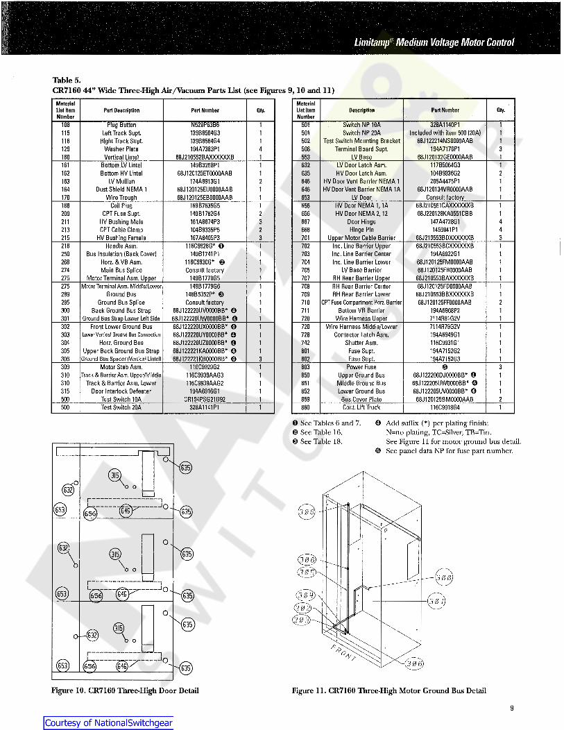
Table 5.CR7160 44” Wide Three-High Air/Vacuum Parts List (see Figures 9, 10 and 11)
MaterialList ItemNumber
MaterielList ItamNumber
Part Number Qty.Part Description Pert Number DescriptionQty.Switch NP 10ASwitch NP 20A
Test Switch Mounting BracketTerminal Board Supt.
LV Base
328A1140P1Included with item 500 (20A)
68J122214NSOOOOAAB194A7176P1
68J120132GE00Q0AAB
1108 Plug ButtonLeft Track Supt.
Right Track Supt.Washer PlateVertical Lintel
N529P63B6139B8564G3139B8564G4194A7383P1
68J210552BAXXXXXXB
50111115 1 5011116 5021
129 34 5081160 1 553
LV Door Latch Asm.HV Door Latch Asm.
HV Door Vent Barrier NEMA 1HV Door Vent Barrier NEMA 1A
LV Door
Bottom LV LintelBottom HV Lintel
LV MullionDust Shield NEMA 1
Wire Trough
117B5064G3104B9336G2205A4475P1
68J120134VROOOOAAB
1161 149B3258P168J120125ET0000AAB
174A8913G168J120125EU0000AAB68J120125EB0000AAB
1 6322162 1 6351163 2 64611164 646
Consult factory 1170 1 653Coil Plug
CPT Fuse Supt.HV Bushing MaleCPT Cable Clamp
HV Bushing Female
HV Door NEMA 1, 1AHV Door NEMA 2, 12
Door HingeHinge Pin
Upper Motor Cable Barrier
68J210551CAXXXXXXB 1169B7635G5149B1782G4161A8674P3104B9335P5167A8405P3
1186 65668J220128KA0551CBB
147A4728G11459941P1
68J210553BDXXXXXXB
1209 2 65643211 6674213 2 6683215 3 701
Handle Asm.Bus Insulation (Back Cover)
Horz. & VB Asm.Inc. Line Barrier UpperInc. Line Barrier CenterInc. Line Barrier Lower
LV Base BarrierRH Rear Barrier Upper
116C9928G* O149B1741P1
116C9930G* ©Consult factory
149B1779G5
1 68J210553BCXXXXXXB194A6922G1
68J120125FM0000AAB68J120125FR0000AAB
68J210553BAXXXXXXB
1218 7021250 1 703
1 1268 704Main Bus Splice
Motor Terminal Asm. Upper1274 1 705
1 1275 707Motor Terminal Asm. Middle/Lower
Ground BusGround Bus Splice
Back Ground Bus StrapGround Bus Strap Lower Left Side
149B1779G6148B5352P* ©Consult factory
68J122220UV0000BB* 068J122220UW0000BB* 0
RH Rear Barrier CenterRH Rear Barrier Lower
CPT Fuse Compartment Horz.BarrierBottom VB Barrier
68J120125FDOOOOAAB68J210553BBXXXXXXB68J120125FF0000AAB
194A6968P27114R81G2V
1275 1 708289 1 709 1
2295 1 7101300 1 711
Wire Harness Upper 1301 1 720Front Lower Ground Bus 68J122220UX0000BB* 0
68J122220UY0000BB* 068J122220UZ0000BB* 068J122221KA0000BB* 068J122221KB0000BB* 0
Wire Harness Middle/LowerContactor Latch Asm.
Shutter Asm.Fuse Supt.Fuse Supt.
7114R79G2V194A6949G1116C9931G1194A7152G2194A7152G3
302 1 720 1303 1 1Lower Vertical Ground Bus Connection 728
Horz. Ground BusUpper Back Ground Bus Strap
Ground Bus Spacer (Vertical Lintel)
1304 1 742305 1 1801
1306 3 802Motor Stab Asm.
Track & Barrier Asm. Upper/MiddleTrack & Barrier Asm. Lower
Door Interlock DefeaterTest Switch 10A
309 116C9929G2116C9939AAG3116C9939AAG2
194A6916G1CR104PSG21B92
1 Power FuseUpper Ground BusMiddle Ground BusLower Ground Bus
Bus Cover Plate
© 380368J122206DJ0000BB* 068J122205UW0000BB* 068J122205UV0000BB* 0
68J120125BM0000AAB
1310 1 850310 1 1851315 1 852 1500 1 859 2
Cont. Lift Truck500 Test Switch 20A 328A1141P1 1 116C9918G4860 1
O See Tables 6 and 7.© See Table 16.© See Table 18.
0 Add suffix (*) per pladng finish:N=no plating, TOSilver, TB=Tin.See Figure 11 for motor ground bus detail.
© See panel data NP for fuse part number.Os''(S)
@°r n
ted(653) (656) @ 'O' ^635)i-
o
ov"'<635) (306)\o o
[3 0 0,r —i x
£r--(Sr Jo(653) " v
^'^635)
(̂635)
3 0 1\
o<&X
©o©§)
1IQ'--<635)
Figure 10. CR7160 Three-High Door Detail Figure 11. CR7160 Three-High Motor Ground Bus Detail
9

Handle Assembly Some parts of the handle assembly are replaceable and can beidentified by part number as shown below:
V
The non-load break isolating mechanism (handle assembly) isa complex construction requiring a special bench fixture toassemble and adjust the mechanical interlocking mechanisms.Therefore, we recommend the entire assembly be replaced ifthe handle mechanism becomes extensively damaged.
© © © ©o
©- dmCIA
'0' •§-Entire assemblies are ordered by catalog number 116C9928G*(see Tables 6 and 7). The group number (G*) is found on anadhesive backed label stuck on the underside of the handlehousing (see Figure 12). For G51, G52 and G55, orderreplacement assemblies Gl, G2 and G5 respectively.
Wiimm9<J
o
& Handle \assembly \
labe! @&
® ® © © © ®Figure 12. CR7160 Handle Assembly
Entire assemblies can be ordered as follows:
Table 6.CR7160 Air Break Handle Assemblies Table 8.
CR7160 Handle Assembly Detail (see Figure 12)Type of Starter Unit Part Number
Figure ItemNumber
Full-voltage non-reversingReduced-voltage non-reversingFull-voltage reversing-standardFull-voltage reversing-mine hoistReduced-voltage reversing
116C9928G1116C9928G5116C9928G2116C9928G 1116C9928G2
Part Description Part Number979B444G* O
205A5718G5723B245G274723B245G273194A7033P4
Brain BoxTest power interlocks with mounting bracketControl power interlocks (2NC)Contactor auxiliary interlock (1N0,1NC)
Sensor bar hook
1567
Wye-deltaPart winding-contactors in seriesPart winding-contactors in parallelTwo-speed, one-windingTwo-speed, two-winding
116C9928G1116C9928G1116C9928G5116C9928G2116C9928G2
9Weld nut assembly for hookHandle housing-standardHandle housing-if key interlockedHandle-standardHandle-if key interlocked
194A7033G1149B1759G1
149B1759AAP1149B1746G1194A7179P1
915151616
Handle retainer clipDepressor FingerSensor Bar
N910P62C6139B8558P4139B8555G2194A1491P1
22Table 7.CR7160 Drawout Vacuum Handle Assemblies 23
24Type of Starter Unit Part Number Cam25
Full-voltage non-reversingReduced-voltage non-reversingFull-voltage reversing-standardFull-voltage reversing-mine hoistReduced-voltage reversing
116C9928G1V116C9928G5V116C9928G2V116C9928G1V116C9928G2V
O * Group numbers for the 979B444 brain box are per starter type asfollows:
Full voltage non-reversingReduced-voltage non-reversingFull-voltage reversingReduced-voltage reversingWye-delta 1M contactor
G12G14
Wye-deltaPart winding-contactors in seriesPart winding-contactors in parallelTwo-speed,one-windingTwo-speed, two-winding
116C9928G1V116C9928G1V116C9928G5V116C9928G2V116C9928G2V
G13G13G12
Wye-delta 2M contactorPart-winding contactors in seriesPart-winding contactors in parallelTwo-speed, one-windingTwo-speed, two-winding
G13G12G14G13G13
10

Limitamp® Medium voltage Motor Control
A one-high vertical bus assembly consists primarily of the busbars, shutter, and operator assembly all constructed as oneitem. The complete assembly is the easiest to replace; howev-er, if the user has the expertise, the bare bus bar assembly canbe installed in the field. The following table is a cross refer-ence from the complete assembly group number,
.194A4480G*, to the bare bus bar assembly, 116C992_G_,shown in the following table.
One-HighHorizontal Bus
Table 9.CR7160 One-High Horizontal Bus Parts
Part NumberPart Description
104B9369P1*O104B9369P1* O ©
Copper 1000ACopper 20QQA
104B9369P9*O104B9369P9* O ©
Copper/Tin Plated 1000ACopper/Tin Plated 2QQQA
See identification sdcker on the verdcal bus assembly for thecorrect group number.
Copper/Silver Plated 100QA
Copper/Silver Plated 20QQA104B9369P2* ©
104B9369P2* O 0 Table 11.CR7160 One-High Vertical Bus Assembly Cross-ReferenceO Consult factory for suffix (*) catalog number and for proper splice
part numbers.© Use QTY6, 908B101P8 spacers per section.© Use QTY6, 908B101P21 spacers per section.© Use QTY6, 908B101P10 spacers per section.
Complete Assembly Bare Bus Assembly
194A4480G16 O194A4480G24 ©194A4480G25 ©
116C9925G10116C9925G15116C9925G16
194A4480G34 O194A4480G35 O194A4480G36 O
116C9925G25116C9925G19116C9925G20
Vertical Bus!*i
194A4480G41 O194A4480G42194A4480G43
116C9926G7116C9925G26116C9925G27
194A4480G44194A4480G46194A4480G47
116C9925G30116C9926G8116C9926G9
© For use with 700-ampere contactor.© 1988 to current date-standard for 400-ampere contactor.©
©© Ground Bus
Table 12.CR7160 One-High Ground Bus Parts
Part Description Part Number
104B9334P1*O104B9334P12* O
Copper 400ACopper 60QA
Copper/Tin Plated 400ACopper/Tin Plated 60QA
104B9334P19* O104B9334P25* OFigure 13. CR7160 Verdcal Bus Assembly
Copper/Silver Plated 400ACopper/Silver Plated 600A
104B9334P15* O104B9334P17* OTable 10.
CR7160 One-High Vertical Bus Assembly Detail (see Figure 13)© Consult factory for suffix (*) catalog number and for proper splice
part number.FigureItem
NumberPartDescriptien Part Number Qty.
Front Vertical Bus CoverShutter Operator Pipe
Contactor Operator Right Hand
116C9921P5139B8559G1
169C6351ATG1 ©
1 12 1
3A 13B Contactor Operator Left Hand
Shutter BracketShutter
169C6351ATG2 ©194A6908P1149B1748P2
14 25 1
Shutter AssemblyHolding Clamp
Pipe Collar
4,5 149B1752G1194A4466P1181A4108P2
16 28 2
Bearing PlateShutter Operator Bearing SupportShutter Operator Right Hand
188A5537G1139B8561G1149B1768G1
9 210 2
11A 111B Shutter Operator Left Hand
Bottom Vertical Bus BarrierMB Insulator (Not Shown)
149B1768G2194A6968P2157C8185P1
112 113 6
© Previous part numbers 149B1749G1, G2. New parts must beordered in pairs when replacing old parts.
11

Two-High Three-High
Table 13.CR7160 Two-High Horizontal and Vertical Bus Parts
Table 16.CR7160 Three-High Horizontal and Vertical Bus Parts
Part Description Part Number Part Description Part NumberCopper 1000ACopper 2000A
116C9952G19 O116C9952G20 O
Copper 1000ACopper 2000A
116C9930G40 O116C993QG41 O
Copper/Tin Plated 1000ACopper/Tin Plated 20Q0A
Copper/Tin Plated 1000ACopper/Tin Plated 2000A
116C9952G17 O116C9952G18 O
116C9930G38 O116C9930G39 O
Copper/Silver Plated 1000ACopper/Silver Plated 2000A
Copper/Silver Plated 1000ACopper/Silver Plated 2000A
116C9930G3 O116C9930G4 0
116C9952G16 O116C9952G14 O
O Consult factory for proper splice part numbers. O Consult factory for proper splice part numbers.
©©©
© © ©©©
©©
©©© ©
©
©©© Figure 15. CR7160
Three-High BusAssembly
Figure 14. CR7160Two-High BusAssembly
Table 17.CR7160 Three-High Bus Assembly Detail (see Figure 15)
Table 14.CR7160 Two-High Bus Assembly Detail (see Figure 14)
Figure RgureItem Part Description Part Number Qty. Item Part Description Part Number Qty.
Number Number116C9921P7139B8559G2194B6318P1116C9921P4
Top Vertical Bus CoverStab and Molding Asm.
Middle Vertical Bus CoverBottom Vertical Bus Cover
116C9921P2139B8559G2116C9921P3116C9921P4
1 Top Vertical Bus CoverStab and Molding Asm.
Middle Vertical Bus CoverBottom Vertical Bus Cover
1 12 1 23 1 34 1 4
Bottom Vertical Bus BarrierMotor Stab AssemblyBus Insulator Barrier
194A6968P2116C9929G2233A2445P1
Bottom Vertical Bus BarrierMotor Stab AssemblyBus Insulator Barrier
194A6968P2116C9929G2233A2445P1
5 1 58 1 89 2 9 2
Table 15.GR7160 Two-High Ground Bus Parts
Table 18.CR7160 Three-High Ground Bus Parts
Part Description Part Number Part Description Part NumberCopper 400ACopper 600A
148B5352P4 ©148B5352P21 O
Copper 400ACopper 6QQA
148B5352P4 O148B5352P21 O
Copper/Tin Plated 400ACopper/Tin Plated 600A
148B5352P29 ©148B5352P28 0
Copper/Tin Plated 400ACopper/Tin Plated 600A
148B5352P29 ©148B5352P28 0
Copper/Silver Plated 400ACopper/Silver Plated 600A
Copper/Silver Plated 400ACopper/Silver Plated 600A
148B5352P11 O148B5352P22 O
148B5352P11 O148B5352P22 Q
O Consult factory for proper splice part numbers. O Consult factory for proper splice part numbers.
12

Limitamp® Medium Voltage Motor Control
CPT Fuse Support Assemblies Intermediate Stab and Track Assembly116C9939AAG2 and G3
CPT primary fuse support assemblies are most easily identi-fied by using the fuse catalog number, type of enclosure (one-high, two-high, three-high) and the matrix below. This willprovide the complete fuse support assembly catalog number.
Track assemblies are used in two- and three-high enclosures tosupport the contactor. This assembly includes the intermedi-ate stabs.
Table 19.CPT Fuse Support Assembly Part Numbers
Enclosure TypeTwo-High
Part NumberFuse PartNumber
One-HighPart Number
Three-HighPart NumberQty. Qty. Qty.
CSC#A480T1E-1CSC#A480T2E-1CSC#A480T3E-1CSC#A480T5E-1
9F60CCB007
55C682289G355C682289G355C682289G355C682289G3104B9352G2
55C682289G355C682289G355C682289G3
149B1782G2149B1782G4194B6370G3
11 11 11
1 t 11
Figure 16. Intermediate Stab and Track Assembly1
Note:Group 2 assemblies are used in both two-high positions and inthe bottom three-high position.
Group 3 assemblies are used in the top and middle three-highpositions only.
Ground Finger assemblies for Group 3 tracks in older starterscan be added to the new Group 3 tracks to make a completereplacement assembly. Ground finger assembly catalognumber: 149B1781G2.
Table 20.Intermediate Stab and Track Assembly Parts (see Figure 16)
FigureItem Part Description Part Number Qty.
Number1 Track Frame
Stab and Molding AssemblyRoller
Barrier (not shown). Mounts onunderside of G3 assembly only
171B6050G1169C6351ASG1
245A7436P1194A6946P1
12 13 44 1
13

Limitamp•Medium Voltage Motor Control
i
These instructions do not purport to cover all details or variations in equipment nor to provide for every possiblecontingency to be met in connection with installation, operation or maintenance. Should further information bedesired or particular problems arise that are not covered sufficiently for the Purchaser’s purposes, the mattershould be referred to die nearest GE sales office.
GE Electrical Distribution & ControlGeneral Electric Company41 Woodford Avenue, Plainville, CT 06062© 1997 General Electric CompanyGEF-4630A 0197 BL