Embed Size (px)
Citation preview
Experience In Motion
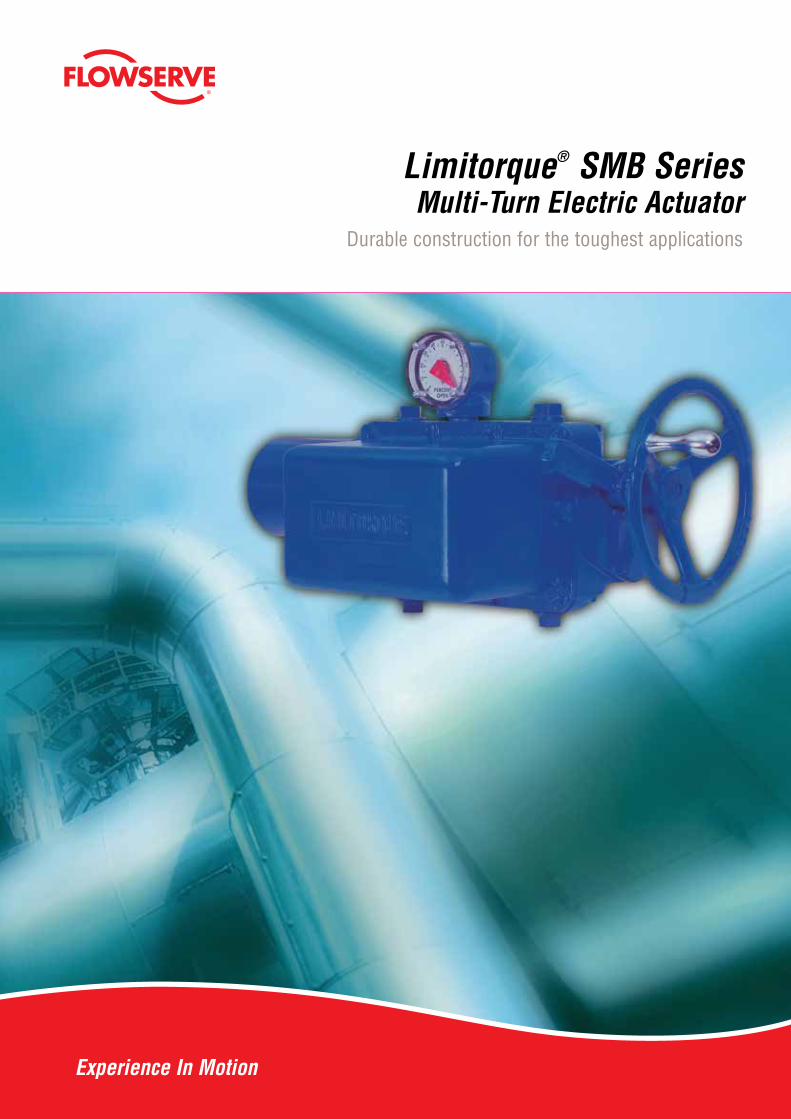
Limitorque® SMB SeriesMulti-Turn Electric Actuator
Durable construction for the toughest applications
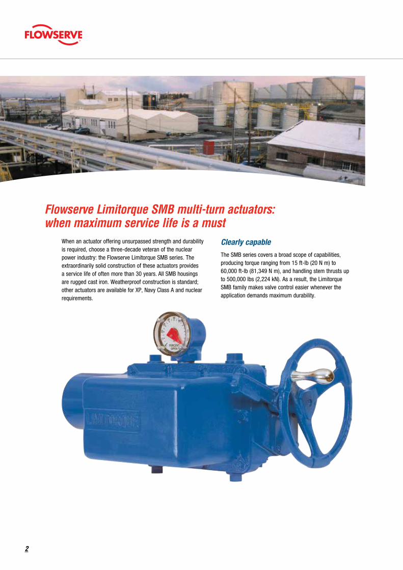
Flowserve Limitorque SMB multi-turn actuators: when maximum service life is a must
When an actuator offering unsurpassed strength and durability is required, choose a three-decade veteran of the nuclear power industry: the Flowserve Limitorque SMB series. The extraordinarily solid construction of these actuators provides a service life of often more than 30 years. All SMB housings are rugged cast iron. Weatherproof construction is standard; other actuators are available for XP, Navy Class A and nuclear requirements.
Clearly capableThe SMB series covers a broad scope of capabilities, producing torque ranging from 15 ft-lb (20 N m) to 60,000 ft-lb (81,349 N m), and handling stem thrusts up to 500,000 lbs (2,224 kN). As a result, the Limitorque SMB family makes valve control easier whenever the application demands maximum durability.
2
A proven performer in the most demanding fields With its durable cast-iron housing, the SMB has long been a mainstay of the nuclear power industry. It was the first actuator to be tested and approved for nuclear power plant reactor containment service. SMB actuators are in service in every major nuclear power generation facility in the world, and on most of the world’s nuclear naval vessels.
And while the SMB is a veteran of the nuclear power field, this actuator’s brawn has proved valuable to many other industries as well. It can capably serve in such applications as:
• Oil and gas wells and platforms
• Oil and gas pipelines
• Petroleum distribution terminals and tank farms
• Petrochemical refineries and hydrocarbon processing plants
• Chemical and specialty chemical plants
• Fossil fuel and nuclear power plants
• Hydroelectric facilities
• Water and wastewater treatment plants
• Dams and flood gates
• Aqueducts and other water distribution systems
• Steam distribution systems
• Mines and ore refineries
• Steelworks and other metals processing plants
• Pulp/paper mills
• Food processing
The SMB has earned its credentials in some of the most critical and strenuous applications around the world. More than 400 Limitorque actuators are at work on every US Navy nuclear aircraft carrier—many of them SMBs. For the Metropolitan Water District of Southern California, Limitorque actuators operate the massive 50-ton, 10-foot-diameter butterfly valves controlling the flow of water into Los Angeles.
And 300 feet beneath the streets of New York City, Limitorque actuators control 96-inch water valves that are subjected to 750,000 ft-lb of torque.
Advanced adaptabilitySpring-compensated versions of the SMB (designated SB and SBD), are available for applications where thermal expansion may pose a jammed-valve risk, or where valve discs are subject to extremely high-speed closure.
The SMB is also a perfect choice for customizing to meet special requirements. Many SMBs have been adapted to control mechanical equipment other than valves in applications requiring precise, powerful linear or rotary motion.
3
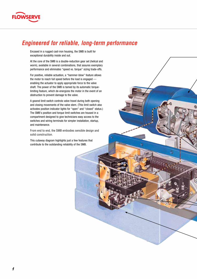
Encased in a rugged cast-iron housing, the SMB is built for exceptional durability inside and out.
At the core of the SMB is a double-reduction gear set (helical and worm), available in several combinations, that assures exemplary performance and eliminates “speed vs. torque” sizing trade-offs.
For positive, reliable actuation, a “hammer-blow” feature allows the motor to reach full speed before the load is engaged — enabling the actuator to apply appropriate force to the valve shaft. The power of the SMB is tamed by its automatic torque-limiting feature, which de-energizes the motor in the event of an obstruction to prevent damage to the valve.
A geared limit switch controls valve travel during both opening and closing movements of the valve stem. (This limit switch also activates position indicator lights for “open” and “closed” status.) The SMB’s position and torque limit switches are housed in a compartment designed to give technicians easy access to the switches and wiring terminals for simpler installation, startup, and maintenance.
From end to end, the SMB embodies sensible design and solid construction.
This cutaway diagram highlights just a few features that contribute to the outstanding reliability of the SMB.
Engineered for reliable, long-term performance
4
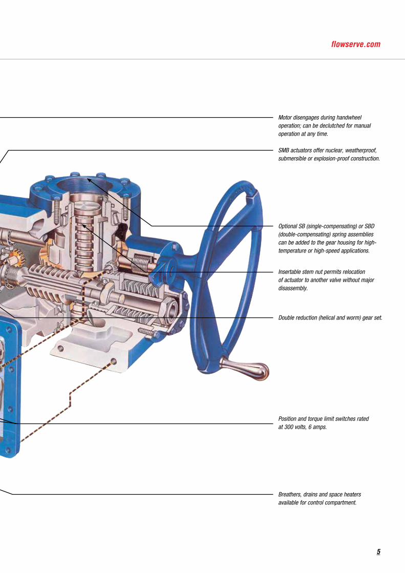
Motor disengages during handwheel operation; can be declutched for manual operation at any time.
SMB actuators offer nuclear, weatherproof, submersible or explosion-proof construction.
Optional SB (single-compensating) or SBD (double-compensating) spring assemblies can be added to the gear housing for high-temperature or high-speed applications.
Insertable stem nut permits relocation of actuator to another valve without major disassembly.
Double reduction (helical and worm) gear set.
Position and torque limit switches rated at 300 volts, 6 amps.
Breathers, drains and space heaters available for control compartment.
5
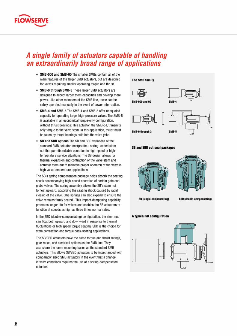
• SMB-000 and SMB-00 The smaller SMBs contain all of the main features of the larger SMB actuators, but are designed for valves requiring smaller operating torque and thrust.
• SMB-0 through SMB-3 These larger SMB actuators are designed to accept larger stem capacities and develop more power. Like other members of the SMB line, these can be safely operated manually in the event of power interruption.
• SMB-4 and SMB-5 The SMB-4 and SMB-5 offer unequaled capacity for operating large, high-pressure valves. The SMB-5 is available in an economical torque-only configuration, without thrust bearings. This actuator, the SMB-5T, transmits only torque to the valve stem. In this application, thrust must be taken by thrust bearings built into the valve yoke.
• SB and SBD options The SB and SBD variations of the standard SMB actuator incorporate a spring-loaded stem nut that permits reliable operation in high-speed or high-temperature service situations. The SB design allows for thermal expansion and contraction of the valve stem and actuator stem nut to maintain proper operaton of the valve in high valve temperature applications.
The SB’s spring compensation package helps absorb the seating shock accompanying high-speed operation of certain gate and globe valves. The spring assembly allows the SB’s stem nut to float upward, absorbing the seating shock caused by rapid closing of the valve. (The springs can also expand to ensure the valve remains firmly seated.) This impact-dampening capability promotes longer life for valves and enables the SB actuators to function at speeds as high as three times normal rates.
In the SBD (double-compensating) configuration, the stem nut can float both upward and downward in response to thermal fluctuations or high speed torque seating. SBD is the choice for stem contraction and torque back-seating applications.
The SB/SBD actuators have the same torque and thrust ratings, gear ratios, and electrical options as the SMB line. They also share the same mounting bases as the standard SMB actuators. This allows SB/SBD actuators to be interchanged with comparably sized SMB actuators in the event that a change in valve conditions requires the use of a spring-compensated actuator.
A single family of actuators capable of handling an extraordinarily broad range of applications
SB (single-compensating) SBD (double-compensating)
A typical SB configuration
SB and SBD optional packages
The SMB family
SMB-4
SMB-5
SMB-000 and 00
SMB-0 through 3
SB (single-compensating) SBD (double-compensating)
A typical SB configuration
SB and SBD optional packages
The SMB family
SMB-4
SMB-5
SMB-000 and 00
SMB-0 through 3
SB (single-compensating) SBD (double-compensating)
A typical SB configuration
SB and SBD optional packages
The SMB family
SMB-4
SMB-5
SMB-000 and 00
SMB-0 through 3
6
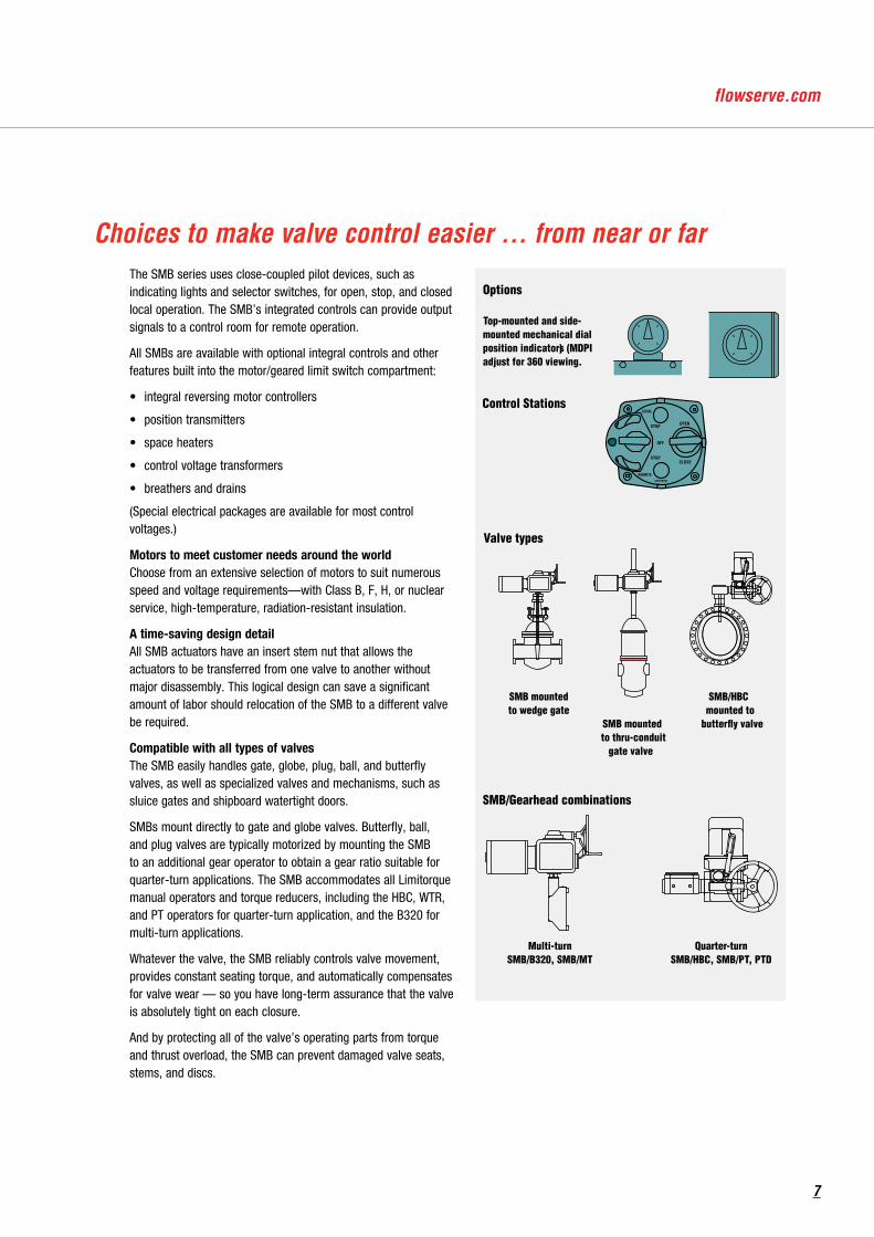
The SMB series uses close-coupled pilot devices, such as indicating lights and selector switches, for open, stop, and closed local operation. The SMB’s integrated controls can provide output signals to a control room for remote operation.
All SMBs are available with optional integral controls and other features built into the motor/geared limit switch compartment:
• integral reversing motor controllers
• position transmitters
• space heaters
• control voltage transformers
• breathers and drains
(Special electrical packages are available for most control voltages.)
Motors to meet customer needs around the world Choose from an extensive selection of motors to suit numerous speed and voltage requirements—with Class B, F, H, or nuclear service, high-temperature, radiation-resistant insulation.
A time-saving design detail All SMB actuators have an insert stem nut that allows the actuators to be transferred from one valve to another without major disassembly. This logical design can save a significant amount of labor should relocation of the SMB to a different valve be required.
Compatible with all types of valves The SMB easily handles gate, globe, plug, ball, and butterfly valves, as well as specialized valves and mechanisms, such as sluice gates and shipboard watertight doors.
SMBs mount directly to gate and globe valves. Butterfly, ball, and plug valves are typically motorized by mounting the SMB to an additional gear operator to obtain a gear ratio suitable for quarter-turn applications. The SMB accommodates all Limitorque manual operators and torque reducers, including the HBC, WTR, and PT operators for quarter-turn application, and the B320 for multi-turn applications.
Whatever the valve, the SMB reliably controls valve movement, provides constant seating torque, and automatically compensates for valve wear — so you have long-term assurance that the valve is absolutely tight on each closure.
And by protecting all of the valve’s operating parts from torque and thrust overload, the SMB can prevent damaged valve seats, stems, and discs.
Choices to make valve control easier … from near or far
Options
Top-mounted and side-mounted mechanical dialposition indicators (MDPI)adjust for 360 viewing.
Valve types
SMB mountedto wedge gate
SMB mountedto thru-conduit
gate valve
SMB/HBCmounted to
butterfly valve
SMB/Gearhead combinations
SMB/B320, SMB/MT
Control Stations
REMOTE
OPENSTOP
CLOSESTOP
OFF
LOCAL
LIMITORQUE
Multi-turnSMB/HBC, SMB/PT, PTD
Quarter-turn
7
Gear housingHousing material – cast iron or ductile iron
Lubrication – MOV long-life EP, NLGI grade 0 grease
Gear reduction – Double reduction type: worm and helical gearing
Worm gear – alloy bronze
Worm – alloy steel
Helical gears – heat-treated steel
MotorDesignation – Example: 60/4P refers to “60 foot-pound – four-pole”. Four-pole is either 1800 RPM (60 Hz) or 1500 RPM (50 Hz); two-pole is either 3600 RPM (60 Hz) or 3000 RPM (50 Hz).
Type – Squirrel-cage induction
Power supply – suitable for 3/60/230, 460 or 575; 3/50/380; or 3/50/415.
Duty – nominal is 15 minutes
Dynamic torque – nominal 20% of start torque
Insulation – Class B standard
Heater – 120 VAC
Limit switchType – gear-driven, snap-acting switch, nuclear grade
Contacts – 16 contacts (4 train) nuclear grade
Contact rating – 300 volts per ICS-125.6; current rated 6 amps resistive and 60 amps inrush at 120 VAC
Torque switchContacts – One SPST contact each for open and closed direction dedicated to actuator torque protection; nuclear grade
Rating – 300 volts per ICS-125.6; current rated 6 amps resistive and 60 amps inrush at 120 VAC
SealsViton
SMB Standard Product SpecificationEnclosureWP actuators – suitable for NEMA 4
XP actuators – suitable for Class 1, Groups C and D, Division 1 service and Class II, Groups E, F and G
Mounting baseSupplied to MSS (English taps) standard
PaintLPS-129. Color blue standard. Valspar epoxy/polyurethane.
Temperature rating-20°F to 150°F (-29°C to 66°C)
Actuator nameplateIncludes the point of manufacture, actuator size, order number, serial number and space for customer tag information. The nameplate also includes the CE stamp. The nameplate is located on the back of the actuator opposite the limit switch compartment.
Motor nameplateThe motor nameplate includes ID number, start torque, run torque, enclosure type, RPM, volts, full load amps, locked rotor amps, insulation class, duty, horsepower, service factor, phase, cycles, motor code, ambient temperature and connection diagram.
XP nameplateActuator can be nameplated as Class 1, Groups C and D, Division 1 and Class II, Groups E, F and G; FM or CSA label.
ControlsNCU (No Controls Actuator) – No additional controls included
INT (Integral Controls) – Includes transformer and reversing contactor
8

Local continuous position indicationLocal position indicator that shows continuous valve position via a dial that is labeled 0-100% OPEN. Indicator is driven by a dedicated gear set that is selected per the application. The SMB-000/0 includes window-mounted dial in MDPI housing bolted on the back of the actuator. The SMB-0-5 includes window-mounted dial in MDPI housing close-coupled to actuator housing.
Local/remote indicationIncludes the Local Continuous Position Indicator with a 1000-ohm potentiometer. The potentiometer is used to transmit valve position to a remote location. One or two potentiometers may be included.
Local/remote nuclear 2000-ohm potentiometer
Includes the Local Continuous Position Indicator with a 2000-ohm, radiation-resistant potentiometer. The potentiometer is used to transmit valve position to a remote location.
Handwheel spurA spur gear attachment that may be added to the actuator to reduce the effort required to operate the handwheel, but requiring more turns.
SMB Commercial and Nuclear Options Product SpecificationOptional handwheelsUsed to reduce the effort required to operate the handwheel.
SB/SBD spring compensation
SB type spring-compensated package for use on high-speed, high-temperature torque-seated applications.
Control StationIncludes three-position selector switch (open, stop, close), two indicating lights (open, intermediate, close indication), and a three-position selector switch (local, off, remote).
MotorOption DC motors are available for some sizes.
Routine motor testTests are conducted in accordance with NEMA MG-1 and IEEE-112.
Other XP categoriesConsult factory.
Note: All options are non-safety related.
9
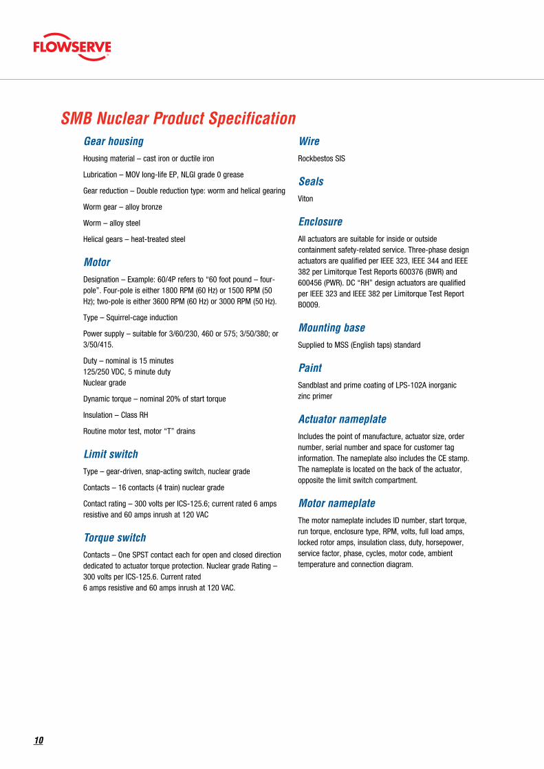
Gear housingHousing material – cast iron or ductile iron
Lubrication – MOV long-life EP, NLGI grade 0 grease
Gear reduction – Double reduction type: worm and helical gearing
Worm gear – alloy bronze
Worm – alloy steel
Helical gears – heat-treated steel
MotorDesignation – Example: 60/4P refers to “60 foot pound – four-pole”. Four-pole is either 1800 RPM (60 Hz) or 1500 RPM (50 Hz); two-pole is either 3600 RPM (60 Hz) or 3000 RPM (50 Hz).
Type – Squirrel-cage induction
Power supply – suitable for 3/60/230, 460 or 575; 3/50/380; or 3/50/415.
Duty – nominal is 15 minutes 125/250 VDC, 5 minute duty Nuclear grade
Dynamic torque – nominal 20% of start torque
Insulation – Class RH
Routine motor test, motor “T” drains
Limit switchType – gear-driven, snap-acting switch, nuclear grade
Contacts – 16 contacts (4 train) nuclear grade
Contact rating – 300 volts per ICS-125.6; current rated 6 amps resistive and 60 amps inrush at 120 VAC
Torque switchContacts – One SPST contact each for open and closed direction dedicated to actuator torque protection. Nuclear grade Rating – 300 volts per ICS-125.6. Current rated 6 amps resistive and 60 amps inrush at 120 VAC.
SMB Nuclear Product SpecificationWireRockbestos SIS
SealsViton
EnclosureAll actuators are suitable for inside or outside containment safety-related service. Three-phase design actuators are qualified per IEEE 323, IEEE 344 and IEEE 382 per Limitorque Test Reports 600376 (BWR) and 600456 (PWR). DC “RH” design actuators are qualified per IEEE 323 and IEEE 382 per Limitorque Test Report B0009.
Mounting baseSupplied to MSS (English taps) standard
PaintSandblast and prime coating of LPS-102A inorganic zinc primer
Actuator nameplateIncludes the point of manufacture, actuator size, order number, serial number and space for customer tag information. The nameplate also includes the CE stamp. The nameplate is located on the back of the actuator, opposite the limit switch compartment.
Motor nameplateThe motor nameplate includes ID number, start torque, run torque, enclosure type, RPM, volts, full load amps, locked rotor amps, insulation class, duty, horsepower, service factor, phase, cycles, motor code, ambient temperature and connection diagram.
10
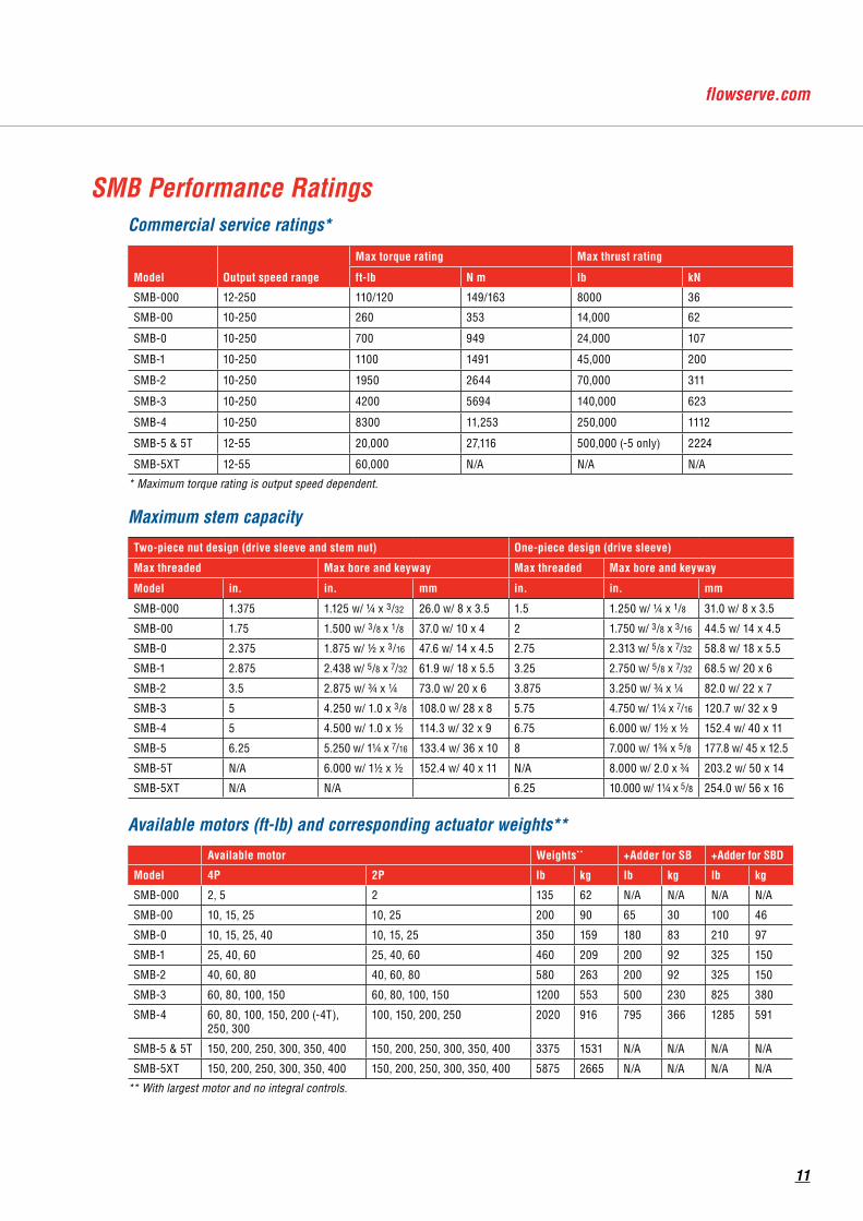
Commercial service ratings*
Model Output speed range
Max torque rating Max thrust rating
ft-lb N m lb kN
SMB-000 12-250 110/120 149/163 8000 36
SMB-00 10-250 260 353 14,000 62
SMB-0 10-250 700 949 24,000 107
SMB-1 10-250 1100 1491 45,000 200
SMB-2 10-250 1950 2644 70,000 311
SMB-3 10-250 4200 5694 140,000 623
SMB-4 10-250 8300 11,253 250,000 1112
SMB-5 & 5T 12-55 20,000 27,116 500,000 (-5 only) 2224
SMB-5XT 12-55 60,000 N/A N/A N/A
* Maximum torque rating is output speed dependent.
Maximum stem capacity
Two-piece nut design (drive sleeve and stem nut) One-piece design (drive sleeve)
Max threaded Max bore and keyway Max threaded Max bore and keyway
Model in. in. mm in. in. mm
SMB-000 1.375 1.125 w/ 1/4 x 3/32 26.0 w/ 8 x 3.5 1.5 1.250 w/ 1/4 x 1/8 31.0 w/ 8 x 3.5
SMB-00 1.75 1.500 w/ 3/8 x 1/8 37.0 w/ 10 x 4 2 1.750 w/ 3/8 x 3/16 44.5 w/ 14 x 4.5
SMB-0 2.375 1.875 w/ 1/2 x 3/16 47.6 w/ 14 x 4.5 2.75 2.313 w/ 5/8 x 7/32 58.8 w/ 18 x 5.5
SMB-1 2.875 2.438 w/ 5/8 x 7/32 61.9 w/ 18 x 5.5 3.25 2.750 w/ 5/8 x 7/32 68.5 w/ 20 x 6
SMB-2 3.5 2.875 w/ 3/4 x 1/4 73.0 w/ 20 x 6 3.875 3.250 w/ 3/4 x 1/4 82.0 w/ 22 x 7
SMB-3 5 4.250 w/ 1.0 x 3/8 108.0 w/ 28 x 8 5.75 4.750 w/ 11/4 x 7/16 120.7 w/ 32 x 9
SMB-4 5 4.500 w/ 1.0 x 1/2 114.3 w/ 32 x 9 6.75 6.000 w/ 11/2 x 1/2 152.4 w/ 40 x 11
SMB-5 6.25 5.250 w/ 11/4 x 7/16 133.4 w/ 36 x 10 8 7.000 w/ 13/4 x 5/8 177.8 w/ 45 x 12.5
SMB-5T N/A 6.000 w/ 11/2 x 1/2 152.4 w/ 40 x 11 N/A 8.000 w/ 2.0 x 3/4 203.2 w/ 50 x 14
SMB-5XT N/A N/A 6.25 10.000 w/ 11/4 x 5/8 254.0 w/ 56 x 16
Available motors (ft-lb) and corresponding actuator weights**
Available motor Weights** +Adder for SB +Adder for SBD
Model 4P 2P lb kg lb kg lb kg
SMB-000 2, 5 2 135 62 N/A N/A N/A N/A
SMB-00 10, 15, 25 10, 25 200 90 65 30 100 46
SMB-0 10, 15, 25, 40 10, 15, 25 350 159 180 83 210 97
SMB-1 25, 40, 60 25, 40, 60 460 209 200 92 325 150
SMB-2 40, 60, 80 40, 60, 80 580 263 200 92 325 150
SMB-3 60, 80, 100, 150 60, 80, 100, 150 1200 553 500 230 825 380
SMB-4 60, 80, 100, 150, 200 (-4T), 250, 300
100, 150, 200, 250 2020 916 795 366 1285 591
SMB-5 & 5T 150, 200, 250, 300, 350, 400 150, 200, 250, 300, 350, 400 3375 1531 N/A N/A N/A N/A
SMB-5XT 150, 200, 250, 300, 350, 400 150, 200, 250, 300, 350, 400 5875 2665 N/A N/A N/A N/A
** With largest motor and no integral controls.
SMB Performance Ratings
11
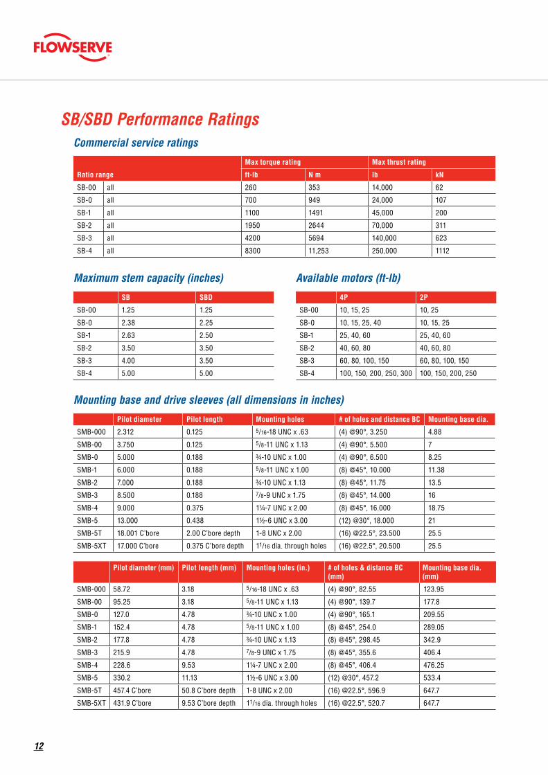
Commercial service ratings
Ratio range
Max torque rating Max thrust rating
ft-lb N m lb kN
SB-00 all 260 353 14,000 62
SB-0 all 700 949 24,000 107
SB-1 all 1100 1491 45,000 200
SB-2 all 1950 2644 70,000 311
SB-3 all 4200 5694 140,000 623
SB-4 all 8300 11,253 250,000 1112
Mounting base and drive sleeves (all dimensions in inches)
Pilot diameter Pilot length Mounting holes # of holes and distance BC Mounting base dia.
SMB-000 2.312 0.125 5/16-18 UNC x .63 (4) @90°, 3.250 4.88
SMB-00 3.750 0.125 5/8-11 UNC x 1.13 (4) @90°, 5.500 7
SMB-0 5.000 0.188 3/4-10 UNC x 1.00 (4) @90°, 6.500 8.25
SMB-1 6.000 0.188 5/8-11 UNC x 1.00 (8) @45°, 10.000 11.38
SMB-2 7.000 0.188 3/4-10 UNC x 1.13 (8) @45°, 11.75 13.5
SMB-3 8.500 0.188 7/8-9 UNC x 1.75 (8) @45°, 14.000 16
SMB-4 9.000 0.375 11/4-7 UNC x 2.00 (8) @45°, 16.000 18.75
SMB-5 13.000 0.438 11/2-6 UNC x 3.00 (12) @30°, 18.000 21
SMB-5T 18.001 C’bore 2.00 C’bore depth 1-8 UNC x 2.00 (16) @22.5°, 23.500 25.5
SMB-5XT 17.000 C’bore 0.375 C’bore depth 11/16 dia. through holes (16) @22.5°, 20.500 25.5
Pilot diameter (mm) Pilot length (mm) Mounting holes (in.) # of holes & distance BC (mm)
Mounting base dia. (mm)
SMB-000 58.72 3.18 5/16-18 UNC x .63 (4) @90°, 82.55 123.95
SMB-00 95.25 3.18 5/8-11 UNC x 1.13 (4) @90°, 139.7 177.8
SMB-0 127.0 4.78 3/4-10 UNC x 1.00 (4) @90°, 165.1 209.55
SMB-1 152.4 4.78 5/8-11 UNC x 1.00 (8) @45°, 254.0 289.05
SMB-2 177.8 4.78 3/4-10 UNC x 1.13 (8) @45°, 298.45 342.9
SMB-3 215.9 4.78 7/8-9 UNC x 1.75 (8) @45°, 355.6 406.4
SMB-4 228.6 9.53 11/4-7 UNC x 2.00 (8) @45°, 406.4 476.25
SMB-5 330.2 11.13 11/2-6 UNC x 3.00 (12) @30°, 457.2 533.4
SMB-5T 457.4 C’bore 50.8 C’bore depth 1-8 UNC x 2.00 (16) @22.5°, 596.9 647.7
SMB-5XT 431.9 C’bore 9.53 C’bore depth 11/16 dia. through holes (16) @22.5°, 520.7 647.7
Maximum stem capacity (inches)
SB SBD
SB-00 1.25 1.25
SB-0 2.38 2.25
SB-1 2.63 2.50
SB-2 3.50 3.50
SB-3 4.00 3.50
SB-4 5.00 5.00
Available motors (ft-lb)
4P 2P
SB-00 10, 15, 25 10, 25
SB-0 10, 15, 25, 40 10, 15, 25
SB-1 25, 40, 60 25, 40, 60
SB-2 40, 60, 80 40, 60, 80
SB-3 60, 80, 100, 150 60, 80, 100, 150
SB-4 100, 150, 200, 250, 300 100, 150, 200, 250
SB/SBD Performance Ratings
12
SB-000
SMB/SB Nominal Center of Gravity
SB-00
SMB-000/00
SMB-00
SMB-0 through 5SB-0 through 4
SB-000
+Z
+Y +Y
+Z
+Y
+Z
+Z
+X
+X
+Z+Y
+Z
+X
+Y
Limitorque
+Z
+X
Limitorque
+X
+Y
+Y
+Z
+X
+Z+Y
Limitorque
+X
+Y
Limitorque
+X
+X
+Z
+Y
+X
Limitorque
+Z
+Y+Z
+X
+X
+Y
Limitorque
SB-00
SMB/SB Nominal Center of Gravity
SB-00
SMB-000/00
SMB-00
SMB-0 through 5SB-0 through 4
SB-000
+Z
+Y +Y
+Z
+Y
+Z
+Z
+X
+X
+Z+Y
+Z
+X
+Y
Limitorque
+Z
+X
Limitorque
+X
+Y
+Y
+Z
+X
+Z+Y
Limitorque
+X
+Y
Limitorque
+X
+X
+Z
+Y
+X
Limitorque
+Z
+Y+Z
+X
+X
+Y
Limitorque
SB-00 through -4
SMB/SB Nominal Center of Gravity
SB-00
SMB-000/00
SMB-00
SMB-0 through 5SB-0 through 4
SB-000
+Z
+Y +Y
+Z
+Y
+Z
+Z
+X
+X
+Z+Y
+Z
+X
+Y
Limitorque
+Z
+X
Limitorque
+X
+Y
+Y
+Z
+X
+Z+Y
Limitorque
+X
+Y
Limitorque
+X
+X
+Z
+Y
+X
Limitorque
+Z
+Y+Z
+X
+X
+Y
Limitorque
SMB-000/00
SMB/SB Nominal Center of Gravity
SB-00
SMB-000/00
SMB-00
SMB-0 through 5SB-0 through 4
SB-000
+Z
+Y +Y
+Z
+Y
+Z
+Z
+X
+X
+Z+Y
+Z
+X
+Y
Limitorque
+Z
+X
Limitorque
+X
+Y
+Y
+Z
+X
+Z+Y
Limitorque
+X
+Y
Limitorque
+X
+X
+Z
+Y
+X
Limitorque
+Z
+Y+Z
+X
+X
+Y
Limitorque
SMB-00
SMB/SB Nominal Center of Gravity
SB-00
SMB-000/00
SMB-00
SMB-0 through 5SB-0 through 4
SB-000
+Z
+Y +Y
+Z
+Y
+Z
+Z
+X
+X
+Z+Y
+Z
+X
+Y
Limitorque
+Z
+X
Limitorque
+X
+Y
+Y
+Z
+X
+Z+Y
Limitorque
+X
+Y
Limitorque
+X
+X
+Z
+Y
+X
Limitorque
+Z
+Y+Z
+X
+X
+Y
Limitorque
SMB-0 through -5
SMB/SB Nominal Center of Gravity
SB-00
SMB-000/00
SMB-00
SMB-0 through 5SB-0 through 4
SB-000
+Z
+Y +Y
+Z
+Y
+Z
+Z
+X
+X
+Z+Y
+Z
+X
+Y
Limitorque
+Z
+X
Limitorque
+X
+Y
+Y
+Z
+X
+Z+Y
Limitorque
+X
+Y
Limitorque
+X
+X
+Z
+Y
+X
Limitorque
+Z
+Y+Z
+X
+X
+Y
Limitorque
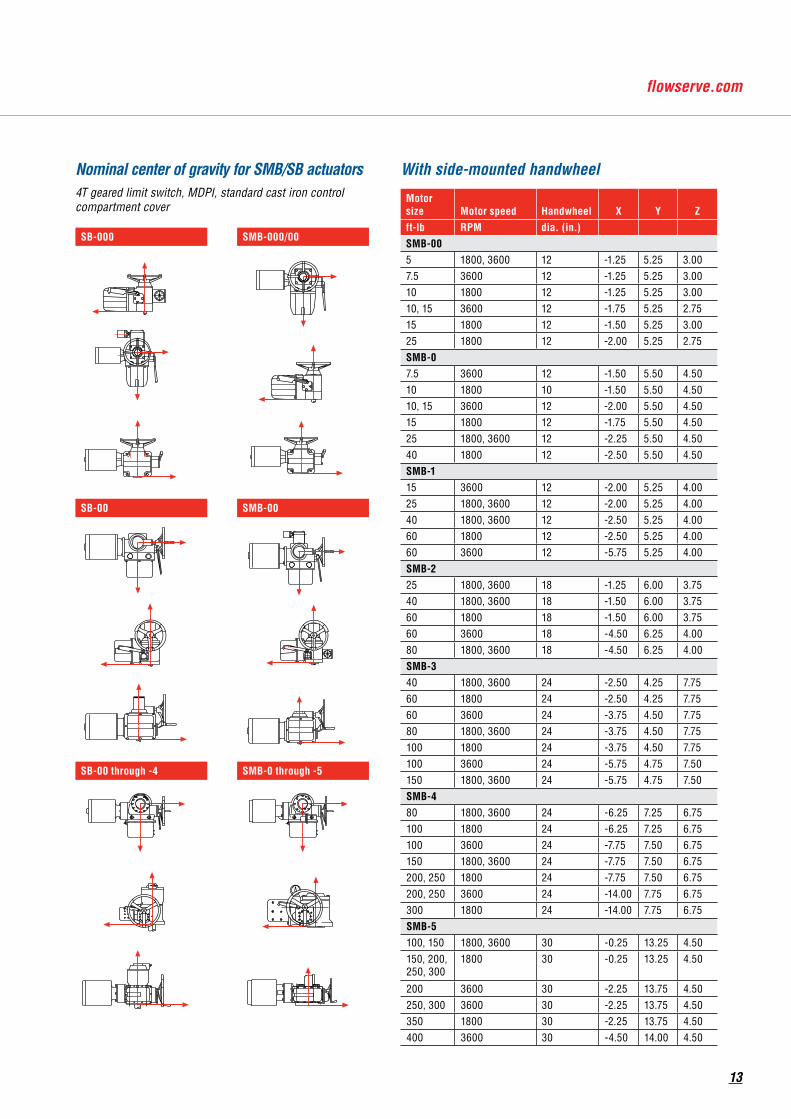
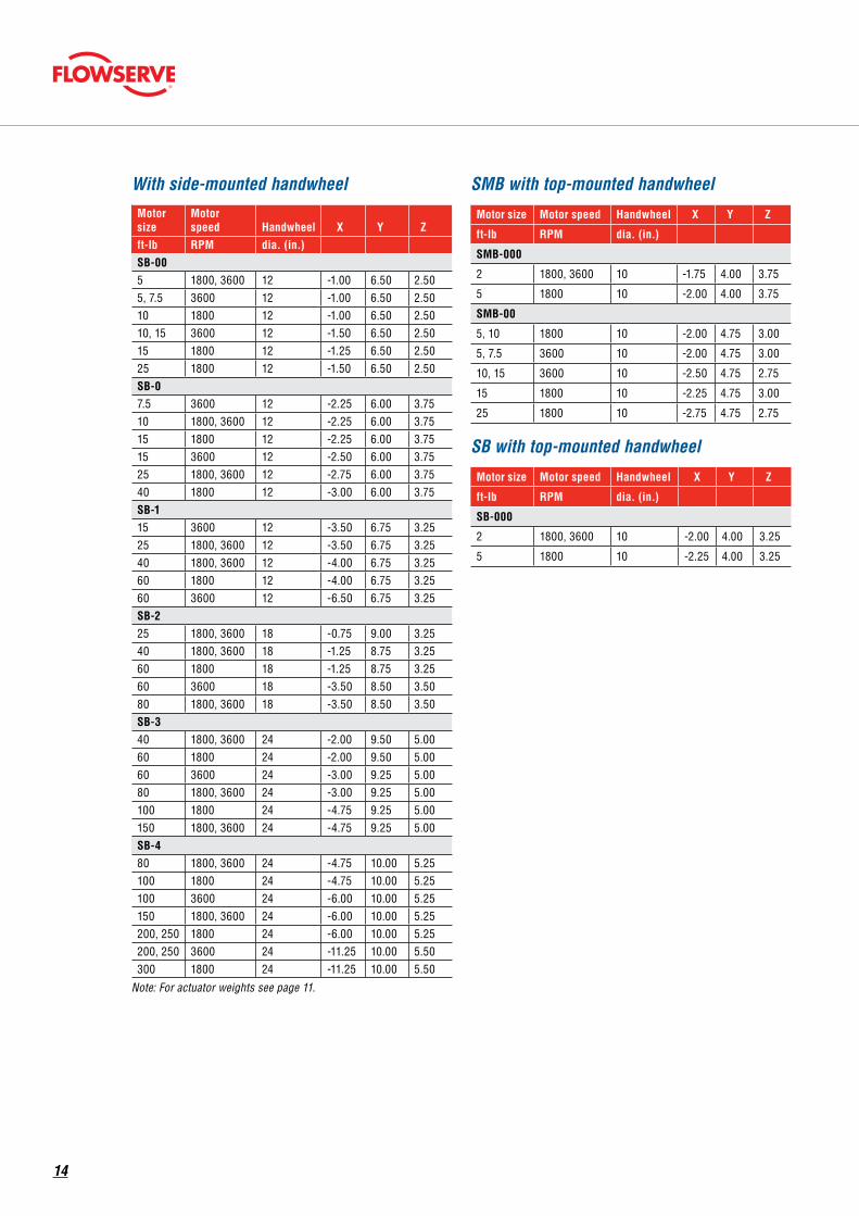
With side-mounted handwheel
Motor size Motor speed Handwheel X Y Zft-lb RPM dia. (in.)SMB-005 1800, 3600 12 -1.25 5.25 3.007.5 3600 12 -1.25 5.25 3.0010 1800 12 -1.25 5.25 3.0010, 15 3600 12 -1.75 5.25 2.7515 1800 12 -1.50 5.25 3.0025 1800 12 -2.00 5.25 2.75SMB-07.5 3600 12 -1.50 5.50 4.5010 1800 10 -1.50 5.50 4.5010, 15 3600 12 -2.00 5.50 4.5015 1800 12 -1.75 5.50 4.5025 1800, 3600 12 -2.25 5.50 4.5040 1800 12 -2.50 5.50 4.50SMB-115 3600 12 -2.00 5.25 4.0025 1800, 3600 12 -2.00 5.25 4.0040 1800, 3600 12 -2.50 5.25 4.0060 1800 12 -2.50 5.25 4.0060 3600 12 -5.75 5.25 4.00SMB-225 1800, 3600 18 -1.25 6.00 3.7540 1800, 3600 18 -1.50 6.00 3.7560 1800 18 -1.50 6.00 3.7560 3600 18 -4.50 6.25 4.0080 1800, 3600 18 -4.50 6.25 4.00SMB-340 1800, 3600 24 -2.50 4.25 7.7560 1800 24 -2.50 4.25 7.7560 3600 24 -3.75 4.50 7.7580 1800, 3600 24 -3.75 4.50 7.75100 1800 24 -3.75 4.50 7.75100 3600 24 -5.75 4.75 7.50150 1800, 3600 24 -5.75 4.75 7.50SMB-480 1800, 3600 24 -6.25 7.25 6.75100 1800 24 -6.25 7.25 6.75100 3600 24 -7.75 7.50 6.75150 1800, 3600 24 -7.75 7.50 6.75200, 250 1800 24 -7.75 7.50 6.75200, 250 3600 24 -14.00 7.75 6.75300 1800 24 -14.00 7.75 6.75SMB-5100, 150 1800, 3600 30 -0.25 13.25 4.50150, 200, 250, 300
1800 30 -0.25 13.25 4.50
200 3600 30 -2.25 13.75 4.50250, 300 3600 30 -2.25 13.75 4.50350 1800 30 -2.25 13.75 4.50400 3600 30 -4.50 14.00 4.50
Nominal center of gravity for SMB/SB actuators4T geared limit switch, MDPI, standard cast iron control compartment cover
13
With side-mounted handwheelMotor size
Motor speed Handwheel X Y Z
ft-lb RPM dia. (in.)SB-005 1800, 3600 12 -1.00 6.50 2.505, 7.5 3600 12 -1.00 6.50 2.5010 1800 12 -1.00 6.50 2.5010, 15 3600 12 -1.50 6.50 2.5015 1800 12 -1.25 6.50 2.5025 1800 12 -1.50 6.50 2.50SB-07.5 3600 12 -2.25 6.00 3.7510 1800, 3600 12 -2.25 6.00 3.7515 1800 12 -2.25 6.00 3.7515 3600 12 -2.50 6.00 3.7525 1800, 3600 12 -2.75 6.00 3.7540 1800 12 -3.00 6.00 3.75SB-115 3600 12 -3.50 6.75 3.2525 1800, 3600 12 -3.50 6.75 3.2540 1800, 3600 12 -4.00 6.75 3.2560 1800 12 -4.00 6.75 3.2560 3600 12 -6.50 6.75 3.25SB-225 1800, 3600 18 -0.75 9.00 3.2540 1800, 3600 18 -1.25 8.75 3.2560 1800 18 -1.25 8.75 3.2560 3600 18 -3.50 8.50 3.5080 1800, 3600 18 -3.50 8.50 3.50SB-340 1800, 3600 24 -2.00 9.50 5.0060 1800 24 -2.00 9.50 5.0060 3600 24 -3.00 9.25 5.0080 1800, 3600 24 -3.00 9.25 5.00100 1800 24 -4.75 9.25 5.00150 1800, 3600 24 -4.75 9.25 5.00SB-480 1800, 3600 24 -4.75 10.00 5.25100 1800 24 -4.75 10.00 5.25100 3600 24 -6.00 10.00 5.25150 1800, 3600 24 -6.00 10.00 5.25200, 250 1800 24 -6.00 10.00 5.25200, 250 3600 24 -11.25 10.00 5.50300 1800 24 -11.25 10.00 5.50
Note: For actuator weights see page 11.
SMB with top-mounted handwheel
Motor size Motor speed Handwheel X Y Z
ft-lb RPM dia. (in.)
SMB-000
2 1800, 3600 10 -1.75 4.00 3.75
5 1800 10 -2.00 4.00 3.75
SMB-00
5, 10 1800 10 -2.00 4.75 3.00
5, 7.5 3600 10 -2.00 4.75 3.00
10, 15 3600 10 -2.50 4.75 2.75
15 1800 10 -2.25 4.75 3.00
25 1800 10 -2.75 4.75 2.75
SB with top-mounted handwheel
Motor size Motor speed Handwheel X Y Z
ft-lb RPM dia. (in.)
SB-000
2 1800, 3600 10 -2.00 4.00 3.25
5 1800 10 -2.25 4.00 3.25
14
Top view
Limitorque
drive sleeve
motor
motor
Envelope
drive sleeve
drive sleeve
1 2" NPT
C L
C L
C L
C L
P
.125 pilot depth
A
mounting base
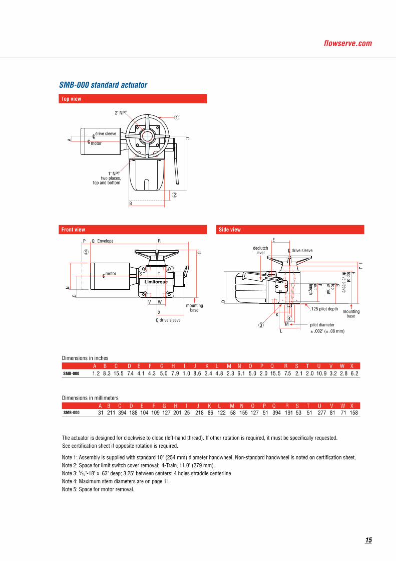
2
SMB-000 Standar d Actuator T op V ie w
Side V ie w Front V ie w
C L
B C
1" NPT two places,
top and bottom
E
declutch lever
D
J H top of drive sleeve
G top of nut
F nut length
K
M L
I
Q
U
N O
T S
V W
X
5
Dimensions in inches
w/ 2-Train GLS
pilot diameter ± .002" (± .08 mm)
4
Dimensions in millimeters
The actuator is designed for clockwise to close (left-hand thread). If other rotation is required, it must be specifica lly requested. See certification sheet if opposite rotation is required.
Note 1: Assembly is supplied with standard 10" (254 mm) diameter handwheel. Non-standard handwheel is noted on certification sheet ..Note 2: Space for limit switch cover removal; 2-Train, 7.5" (190 mm); 4-Train , 11.0" (279 mm). Note 3: 5∕16"-18" x .63" deep; 3.25" between centers; 4 holes straddle centerline.Note 4: Maximum stem diameters are on page 11.Note 5: Space for motor removal.
3
mounting base
w/ 4-Train GLS
w/ 2-Train GLS
w/ 4-Train GLS
R
SMB-000 standard actuator
Front view
Limitorque
drive sleeve
motor
motor
Envelope
drive sleeve
drive sleeve
1 2" NPT
C L
C L
C L
C L
P
.125 pilot depth
A
mounting base
2
SMB-000 Standar d Actuator T op V ie w
Side V ie w Front V ie w
C L
B C
1" NPT two places,
top and bottom
E
declutch lever
D
J H top of drive sleeve
G top of nut
F nut length
K
M L
I
Q
U
N O
T S
V W
X
5
Dimensions in inches
w/ 2-Train GLS
pilot diameter ± .002" (± .08 mm)
4
Dimensions in millimeters
The actuator is designed for clockwise to close (left-hand thread). If other rotation is required, it must be specifica lly requested. See certification sheet if opposite rotation is required.
Note 1: Assembly is supplied with standard 10" (254 mm) diameter handwheel. Non-standard handwheel is noted on certification sheet ..Note 2: Space for limit switch cover removal; 2-Train, 7.5" (190 mm); 4-Train , 11.0" (279 mm). Note 3: 5∕16"-18" x .63" deep; 3.25" between centers; 4 holes straddle centerline.Note 4: Maximum stem diameters are on page 11.Note 5: Space for motor removal.
3
mounting base
w/ 4-Train GLS
w/ 2-Train GLS
w/ 4-Train GLS
R
Side view
Limitorque
drive sleeve
motor
motor
Envelope
drive sleeve
drive sleeve
1 2" NPT
C L
C L
C L
C L
P
.125 pilot depth
A
mounting base
2
SMB-000 Standar d Actuator T op V ie w
Side V ie w Front V ie w
C L
B C
1" NPT two places,
top and bottom
E
declutch lever
D
J H top of drive sleeve
G top of nut
F nut length
K
M L
I
Q
U
N O
T S
V W
X
5
Dimensions in inches
w/ 2-Train GLS
pilot diameter ± .002" (± .08 mm)
4
Dimensions in millimeters
The actuator is designed for clockwise to close (left-hand thread). If other rotation is required, it must be specifica lly requested. See certification sheet if opposite rotation is required.
Note 1: Assembly is supplied with standard 10" (254 mm) diameter handwheel. Non-standard handwheel is noted on certification sheet ..Note 2: Space for limit switch cover removal; 2-Train, 7.5" (190 mm); 4-Train , 11.0" (279 mm). Note 3: 5∕16"-18" x .63" deep; 3.25" between centers; 4 holes straddle centerline.Note 4: Maximum stem diameters are on page 11.Note 5: Space for motor removal.
3
mounting base
w/ 4-Train GLS
w/ 2-Train GLS
w/ 4-Train GLS
R
Limitorque
drive sleeve
motor
motor
Envelope
drive sleeve
drive sleeve
12" NPT
CL
CL
CL
CL
P
.125 pilot depth
A
mountingbase
2
SMB-000 Standard ActuatorTop View
Side ViewFront View
CL
B
C
1" NPTtwo places,
top and bottom
E
declutchlever
D
J
Htop ofdrive sleeve
Gtopof nut
Fnutlength
K
ML
I
Q
U
NO
TS
V W
X
5
Dimensions in inches
pilot diameter ± .002" (± .08 mm)
4
Dimensions in millimeters
The actuator is designed for clockwise to close (left-hand thread). If other rotation is required, it must be specifically requested.See certification sheet if opposite rotation is required.
Note 1: Assembly is supplied with standard 10" (254 mm) diameter handwheel. Non-standard handwheel is noted on certification sheet..Note 2: Space for limit switch cover removal; 4-Train, 11.0" (279 mm).Note 3: 5∕16"-18" x .63" deep; 3.25" between centers; 4 holes straddle centerline.Note 4: Maximum stem diameters are on page 11.Note 5: Space for motor removal.
3
mountingbase
SMB-000
SMB-000
R
15
16
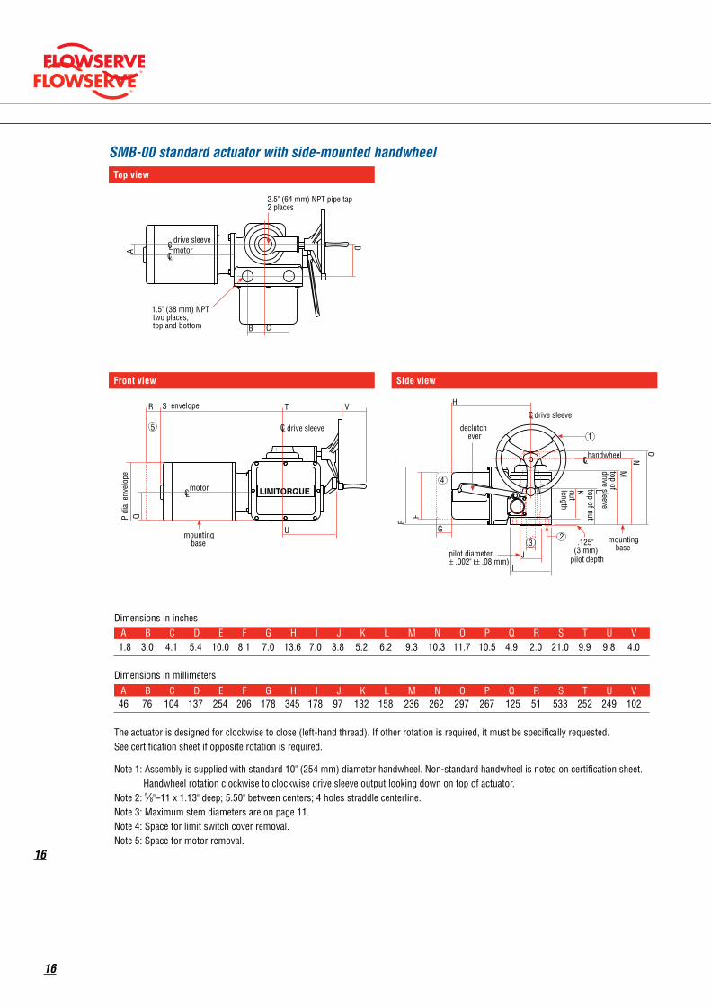
Top viewSMB-00 Standar d Actuator with Side Mounted Handwheel T op Vi ew
Side Vi ew
motor drive sleeve
C L C L
C
A
B
2.5" (64 mm) NPT pipe tap2 places
D
E
H
F
I
pilot diameter± .002" ( ± .08 mm)
mounting base
G
K nut length
L top of nut
top of drive sleeve
N
O
Front Vi ew
drive sleeve C L
handwheel
J 3 .125"
(3 mm) pilot depth
1
2
Dimensions in inchesA B C D E F G H I J K L M N O P Q R S T U V
Dimensions in millimeters
The actuator is designed for clockwise to close (left-hand thread). If other rotation is required, it must be specifica lly requested. See certification sheet if opposite rotation is required.
Note 1: Assembly is supplied with standard 10" (254 mm) diameter handwheel. Non-standard handwheel is noted on certification she et. Handwheel rotation clockwise to clockwise drive sleeve output looking down on top of actuator.
Note 2: 5∕8"–11 x 1.13" deep; 5.50" between centers; 4 holes straddle centerline.Note 3: Maximum stem diameters are on page 11.Note 4: Space for limit switch cover removal. Note 5: Space for motor removal.
declutch lever
C L
LIMITORQUEmotor
drive sleeve
R
P di
a. e
nvel
ope
Q
S envelope T
U
V
C L
mounting base
5
1.5" (38 mm) NPT two places, top and bottom
M
4
1.8 3.0 4.1 5.4 10.0 8.1 7.0 13.6 7.0 3.8 5.2 6.2 9.3 10.3 11.7 10.5 4.9 2.0 21.0 9.9 9.8 4.0
A B C D E F G H I J K L M N O P Q R S T U V 46 76 104 137 254 206 178 345 178 97 132 158 236 262 297 267 125 51 533 252 249 102
C L
SMB-00 standard actuator with side-mounted handwheel
Front view
SMB-00 Standar d Actuator with Side Mounted Handwheel T op Vi ew
Side Vi ew
motor drive sleeve
C L C L
C
A
B
2.5" (64 mm) NPT pipe tap2 places
D
E H
F
I
pilot diameter± .002" ( ± .08 mm)
mounting base
G
K nut length
L top of nut
top of drive sleeve
N
O
Front Vi ew
drive sleeve C L
handwheel
J 3 .125"
(3 mm) pilot depth
1
2
Dimensions in inchesA B C D E F G H I J K L M N O P Q R S T U V
Dimensions in millimeters
The actuator is designed for clockwise to close (left-hand thread). If other rotation is required, it must be specifica lly requested. See certification sheet if opposite rotation is required.
Note 1: Assembly is supplied with standard 10" (254 mm) diameter handwheel. Non-standard handwheel is noted on certification she et. Handwheel rotation clockwise to clockwise drive sleeve output looking down on top of actuator.
Note 2: 5∕8"–11 x 1.13" deep; 5.50" between centers; 4 holes straddle centerline.Note 3: Maximum stem diameters are on page 11.Note 4: Space for limit switch cover removal. Note 5: Space for motor removal.
declutch lever
C L
LIMITORQUEmotor
drive sleeve
R
P di
a. e
nvel
ope
Q
S envelope T
U
V
C L
mounting base
5
1.5" (38 mm) NPT two places, top and bottom
M
4
1.8 3.0 4.1 5.4 10.0 8.1 7.0 13.6 7.0 3.8 5.2 6.2 9.3 10.3 11.7 10.5 4.9 2.0 21.0 9.9 9.8 4.0
A B C D E F G H I J K L M N O P Q R S T U V 46 76 104 137 254 206 178 345 178 97 132 158 236 262 297 267 125 51 533 252 249 102
C L
Side view
SMB-00 Standar d Actuator with Side Mounted Handwheel T op Vi ew
Side Vi ew
motor drive sleeve
C L C L
C
A
B
2.5" (64 mm) NPT pipe tap2 places
D
E H
F
I
pilot diameter± .002" ( ± .08 mm)
mounting base
G
K nut length
L top of nut
top of drive sleeve
N
O
Front Vi ew
drive sleeve C L
handwheel
J 3 .125"
(3 mm) pilot depth
1
2
Dimensions in inchesA B C D E F G H I J K L M N O P Q R S T U V
Dimensions in millimeters
The actuator is designed for clockwise to close (left-hand thread). If other rotation is required, it must be specifica lly requested. See certification sheet if opposite rotation is required.
Note 1: Assembly is supplied with standard 10" (254 mm) diameter handwheel. Non-standard handwheel is noted on certification she et. Handwheel rotation clockwise to clockwise drive sleeve output looking down on top of actuator.
Note 2: 5∕8"–11 x 1.13" deep; 5.50" between centers; 4 holes straddle centerline.Note 3: Maximum stem diameters are on page 11.Note 4: Space for limit switch cover removal. Note 5: Space for motor removal.
declutch lever
C L
LIMITORQUEmotor
drive sleeve
R
P di
a. e
nvel
ope
Q
S envelope T
U
V
C L
mounting base
5
1.5" (38 mm) NPT two places, top and bottom
M
4
1.8 3.0 4.1 5.4 10.0 8.1 7.0 13.6 7.0 3.8 5.2 6.2 9.3 10.3 11.7 10.5 4.9 2.0 21.0 9.9 9.8 4.0
A B C D E F G H I J K L M N O P Q R S T U V 46 76 104 137 254 206 178 345 178 97 132 158 236 262 297 267 125 51 533 252 249 102
C L
SMB-00 Standar d Actuator with Side Mounted Handwheel T op Vi ew
Side Vi ew
motor drive sleeve
C L C L
C
A
B
2.5" (64 mm) NPT pipe tap2 places
D
E
H F
I
pilot diameter± .002" ( ± .08 mm)
mounting base
G
K nut length
L top of nut
top of drive sleeve
N
O
Front Vi ew
drive sleeve C L
handwheel
J 3 .125"
(3 mm) pilot depth
1
2
Dimensions in inchesA B C D E F G H I J K L M N O P Q R S T U V
Dimensions in millimeters
The actuator is designed for clockwise to close (left-hand thread). If other rotation is required, it must be specifica lly requested. See certification sheet if opposite rotation is required.
Note 1: Assembly is supplied with standard 10" (254 mm) diameter handwheel. Non-standard handwheel is noted on certification she et. Handwheel rotation clockwise to clockwise drive sleeve output looking down on top of actuator.
Note 2: 5∕8"–11 x 1.13" deep; 5.50" between centers; 4 holes straddle centerline.Note 3: Maximum stem diameters are on page 11.Note 4: Space for limit switch cover removal. Note 5: Space for motor removal.
declutch lever
C L
LIMITORQUEmotor
drive sleeve
R
P di
a. e
nvel
ope
Q
S envelope T
U
V
C L
mounting base
5
1.5" (38 mm) NPT two places, top and bottom
M
4
1.8 3.0 4.1 5.4 10.0 8.1 7.0 13.6 7.0 3.8 5.2 6.2 9.3 10.3 11.7 10.5 4.9 2.0 21.0 9.9 9.8 4.0
A B C D E F G H I J K L M N O P Q R S T U V 46 76 104 137 254 206 178 345 178 97 132 158 236 262 297 267 125 51 533 252 249 102
C L
16
flowserve.com
CL
CL
CL
CLCL
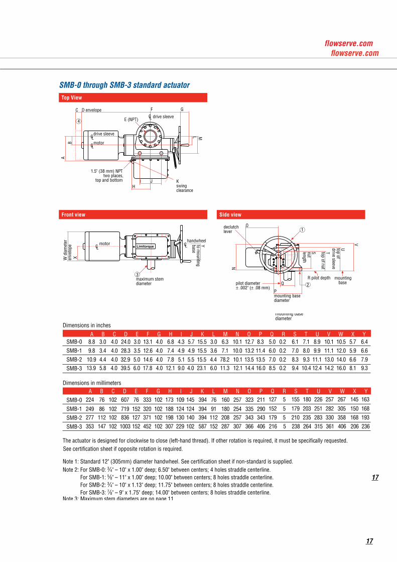
SMB-0 through 3 Standard ActuatorTop View
Side View Front View
Dimensions in inches
SMB-0
SMB-1
SMB-2
SMB-3
handwheel
23maximum stemdiameter
mountingbase
1.5" (38 mm) NPTtwo places,
top and bottom
motor
motor
V
Ttop of nut
Snutlength
R pilot depthQ
Utop ofdrive sleeveW
dia
met
eren
velo
pe
C D envelope
BA
declutchlever
Pmounting basediameter
E (NPT)
Limitorque
N
O
MLI J
HKswingclearance
Yto mounting
base
X
GF
drive sleeve
drive sleeve4
pilot diameter± .002" (± .08 mm)
1
Dimensions in millimeters
SMB-0
SMB-1
SMB-2
SMB-3
The actuator is designed for clockwise to close (left-hand thread). If other rotation is required, it must be specifically requested.See certification sheet if opposite rotation is required.
Note 1: Standard 12" (305mm) diameter handwheel. See certification sheet if non-standard is supplied.Note 2: For SMB-0: 3∕4" – 10" x 1.00" deep; 6.50" between centers; 4 holes straddle centerline. For SMB-1: 5∕8" – 11" x 1.00" deep; 10.00" between centers; 8 holes straddle centerline. For SMB-2: 3∕4" – 10" x 1.13" deep; 11.75" between centers; 8 holes straddle centerline. For SMB-3: 7∕8" – 9" x 1.75" deep; 14.00" between centers; 8 holes straddle centerline.Note 3: Maximum stem diameters are on page 11.Note 4: Space for motor removal.
A B C D E F G H I J K L M N O P Q R S T U V W X Y
A B C D E F G H I J K L M N O P Q R S T U V W X Y224 76 102 607 76 333 102 173 109 145 394 76 160 257 323 211 127 5 155 180 226 257 267 145 163
152 5 179 203 251 282 305 150 168249 86 102 719 152 320 102 188 124 124 394 91 180 254 335 290179 5 210 235 283 330 358 168 193
216 5 238 264 315 361 406 206 236
277 112 102 836 127 371 102 198 130 140 394 112 208 257 343 343
353 147 102 1003 152 452 102 307 229 102 587 152 287 307 366 406
8.8 3.0 4.0 24.0 3.0 13.1 4.0 6.8 4.3 5.7 15.5 3.0 6.3 10.1 12.7 8.3 5.0 0.2 6.1 7.1 8.9 10.1 10.5 5.7 6.4
9.8 3.4 4.0 28.3 3.5 12.6 4.0 7.4 4.9 4.9 15.5 3.6 7.1 10.0 13.2 11.4 6.0 0.2 7.0 8.0 9.9 11.1 12.0 5.9 6.6
7.0 0.2 8.3 9.3 11.1 13.0 14.0 6.6 7.910.9 4.4 4.0 32.9 5.0 14.6 4.0 7.8 5.1 5.5 15.5 4.4 78.2 10.1 13.5 13.513.9 5.8 4.0 39.5 6.0 17.8 4.0 12.1 9.0 4.0 23.1 6.0 11.3 12.1 14.4 16.0 8.5 0.2 9.4 10.4 12.4 14.2 16.0 8.1 9.3
Top View
C L
C L
C L
C L C L
SMB-0 thr ough 3 Standar d Actuator Top View
Side View Front View
Dimensions in inches
SMB-0
SMB-1
SMB-2
SMB-3
handwheel
2 3 maximum stem diameter
mounting base
1.5" (38 mm) NP T two places,
top and bottom
motor
motor
V
T top of nut
S nut length
R pilot depth Q
U top of drive sleeve
W d
iam
eter
en
velo
pe
C D envelope
B A
declutch lever
P mounting base diameter
E (NP T)
Limitorque
N O
M
L
I J H
K swing clearance
Y to mounting
base
X
G F
drive sleeve
drive sleeve 4
pilot diameter ± .002" (± .08 mm)
1
Dimensions in millimeters
SMB-0
SMB-1
SMB-2
SMB-3
The actuator is designed for clockwise to close (left-hand thread). If other rotation is required, it must be specifica lly requested. See certification sheet if opposite rotation is required.
Note 1: Standard 12" (305mm) diameter handwheel. See certification sheet if non-standard is supplied. Note 2: For SMB-0: 3∕4" – 10" x 1.00" deep; 6.50" between centers; 4 holes straddle centerline. For SMB-1: 5∕8" – 11" x 1.00" deep; 10.00" between centers; 8 holes straddle centerline. For SMB-2: 3∕4" – 10" x 1.13" deep; 11.75" between centers; 8 holes straddle centerline. For SMB-3: 7∕8" – 9" x 1.75" deep; 14.00" between centers; 8 holes straddle centerline.Note 3: Maximum stem diameters are on page 11.Note 4: Space for motor removal.
A B C D E F G H I J K L M N O P Q R S T U V W X Y
A B C D E F G H I J K L M N O P Q R S T U V W X Y 224 76 102 607 76 333 102 173 109 145 394 76 160 257 404 211 127 5 155 180 226 257 267 145 163
152 5 179 203 251 282 305 150 168249 86 102 719 152 333 102 188 124 124 394 91 180 254 427 290179 5 210 235 283 330 358 168 193
216 5 238 264 315 361 406 206 236
277 112 102 836 127 333 102 198 130 140 394 112 208 257 455 343
353 147 102 1003 152 452 102 307 229 102 587 152 287 307 518 406
8.8 3.0 4.0 24.0 3.0 13.1 4.0 6.8 4.3 5.7 15.5 3.0 6.3 10.1 15.9 8.3 5.0 0.2 6.1 7.1 8.9 10.1 10.5 5.7 6.4
9.8 3.4 4.0 28.3 3.5 13.1 4.0 7.4 4.9 4.9 15.5 3.6 7.1 10.0 16.8 11.4 6.0 0.2 7.0 8.0 9.9 11.1 12.0 5.9 6.6
7.0 0.2 8.3 9.3 11.1 13.0 14.0 6.6 7.910.9 4.4 4.0 32.9 5.0 13.1 4.0 7.8 5.1 5.5 15.5 4.4 78.2 10.1 17.9 13.513.9 5.8 4.0 39.5 6.0 17.8 4.0 12.1 9.0 4.0 23.1 6.0 11.3 12.1 20.4 16.0 8.5 0.2 9.4 10.4 12.4 14.2 16.0 8.1 9.3
SMB-0 through SMB-3 standard actuator
Front view
C L
C L
C L
C L C L
SMB-0 thr ough 3 Standar d Actuator Top View
Side View Front View
Dimensions in inches
SMB-0
SMB-1
SMB-2
SMB-3
handwheel
2 3 maximum stem diameter
mounting base
1.5" (38 mm) NP T two places,
top and bottom
motor
motor
V
T top of nut
S nut length
R pilot depth Q
U top of drive sleeve
W d
iam
eter
en
velo
pe
C D envelope
B A
declutch lever
P mounting base diameter
E (NP T)
Limitorque
N O
M
L
I J H
K swing clearance
Y to mounting
base
X
G F
drive sleeve
drive sleeve 4
pilot diameter ± .002" (± .08 mm)
1
Dimensions in millimeters
SMB-0
SMB-1
SMB-2
SMB-3
The actuator is designed for clockwise to close (left-hand thread). If other rotation is required, it must be specifica lly requested. See certification sheet if opposite rotation is required.
Note 1: Standard 12" (305mm) diameter handwheel. See certification sheet if non-standard is supplied. Note 2: For SMB-0: 3∕4" – 10" x 1.00" deep; 6.50" between centers; 4 holes straddle centerline. For SMB-1: 5∕8" – 11" x 1.00" deep; 10.00" between centers; 8 holes straddle centerline. For SMB-2: 3∕4" – 10" x 1.13" deep; 11.75" between centers; 8 holes straddle centerline. For SMB-3: 7∕8" – 9" x 1.75" deep; 14.00" between centers; 8 holes straddle centerline.Note 3: Maximum stem diameters are on page 11.Note 4: Space for motor removal.
A B C D E F G H I J K L M N O P Q R S T U V W X Y
A B C D E F G H I J K L M N O P Q R S T U V W X Y 224 76 102 607 76 333 102 173 109 145 394 76 160 257 404 211 127 5 155 180 226 257 267 145 163
152 5 179 203 251 282 305 150 168249 86 102 719 152 333 102 188 124 124 394 91 180 254 427 290179 5 210 235 283 330 358 168 193
216 5 238 264 315 361 406 206 236
277 112 102 836 127 333 102 198 130 140 394 112 208 257 455 343
353 147 102 1003 152 452 102 307 229 102 587 152 287 307 518 406
8.8 3.0 4.0 24.0 3.0 13.1 4.0 6.8 4.3 5.7 15.5 3.0 6.3 10.1 15.9 8.3 5.0 0.2 6.1 7.1 8.9 10.1 10.5 5.7 6.4
9.8 3.4 4.0 28.3 3.5 13.1 4.0 7.4 4.9 4.9 15.5 3.6 7.1 10.0 16.8 11.4 6.0 0.2 7.0 8.0 9.9 11.1 12.0 5.9 6.6
7.0 0.2 8.3 9.3 11.1 13.0 14.0 6.6 7.910.9 4.4 4.0 32.9 5.0 13.1 4.0 7.8 5.1 5.5 15.5 4.4 78.2 10.1 17.9 13.513.9 5.8 4.0 39.5 6.0 17.8 4.0 12.1 9.0 4.0 23.1 6.0 11.3 12.1 20.4 16.0 8.5 0.2 9.4 10.4 12.4 14.2 16.0 8.1 9.3
Side view
C L
C L
C L
C L C L
SMB-0 thr ough 3 Standar d Actuator Top View
Side View Front View
Dimensions in inches
SMB-0
SMB-1
SMB-2
SMB-3
handwheel
2 3 maximum stem diameter
mounting base
1.5" (38 mm) NP T two places,
top and bottom
motor
motor
V
T top of nut
S nut length
R pilot depth Q
U top of drive sleeve
W d
iam
eter
en
velo
pe
C D envelope
B A
declutch lever
P mounting base diameter
E (NP T)
Limitorque
N
O
M
L I J
H K swing clearance
Y to mounting
base
X
G F
drive sleeve
drive sleeve 4
pilot diameter ± .002" (± .08 mm)
1
Dimensions in millimeters
SMB-0
SMB-1
SMB-2
SMB-3
The actuator is designed for clockwise to close (left-hand thread). If other rotation is required, it must be specifica lly requested. See certification sheet if opposite rotation is required.
Note 1: Standard 12" (305mm) diameter handwheel. See certification sheet if non-standard is supplied. Note 2: For SMB-0: 3∕4" – 10" x 1.00" deep; 6.50" between centers; 4 holes straddle centerline. For SMB-1: 5∕8" – 11" x 1.00" deep; 10.00" between centers; 8 holes straddle centerline. For SMB-2: 3∕4" – 10" x 1.13" deep; 11.75" between centers; 8 holes straddle centerline. For SMB-3: 7∕8" – 9" x 1.75" deep; 14.00" between centers; 8 holes straddle centerline.Note 3: Maximum stem diameters are on page 11.Note 4: Space for motor removal.
A B C D E F G H I J K L M N O P Q R S T U V W X Y
A B C D E F G H I J K L M N O P Q R S T U V W X Y 224 76 102 607 76 333 102 173 109 145 394 76 160 257 404 211 127 5 155 180 226 257 267 145 163
152 5 179 203 251 282 305 150 168249 86 102 719 152 333 102 188 124 124 394 91 180 254 427 290179 5 210 235 283 330 358 168 193
216 5 238 264 315 361 406 206 236
277 112 102 836 127 333 102 198 130 140 394 112 208 257 455 343
353 147 102 1003 152 452 102 307 229 102 587 152 287 307 518 406
8.8 3.0 4.0 24.0 3.0 13.1 4.0 6.8 4.3 5.7 15.5 3.0 6.3 10.1 15.9 8.3 5.0 0.2 6.1 7.1 8.9 10.1 10.5 5.7 6.4
9.8 3.4 4.0 28.3 3.5 13.1 4.0 7.4 4.9 4.9 15.5 3.6 7.1 10.0 16.8 11.4 6.0 0.2 7.0 8.0 9.9 11.1 12.0 5.9 6.6
7.0 0.2 8.3 9.3 11.1 13.0 14.0 6.6 7.910.9 4.4 4.0 32.9 5.0 13.1 4.0 7.8 5.1 5.5 15.5 4.4 78.2 10.1 17.9 13.513.9 5.8 4.0 39.5 6.0 17.8 4.0 12.1 9.0 4.0 23.1 6.0 11.3 12.1 20.4 16.0 8.5 0.2 9.4 10.4 12.4 14.2 16.0 8.1 9.3
17
17
Top view
C L
C L
C L
C L Limitorque
pilot diameter ± .003" (.08 mm)
CC
BB pilot dept h
Y
AA diameter
mounting base
X
handwheel
4
C L
C L handwheel
T nut lengt h
U top of nut
V top of drive sleeve
W
mounting base S bolt circle diameter
3
O P
R
Q
declutch lever 2
drive sleeve
SMB-4 Standard Actuator T op Vi ew
Side Vi ew Front V ie w
Dimensions in inches
SMB-4
drive sleeve
motor
drive sleeve H
(NPT)
E envelope D
C B
2" (51 mm) NPTtwo places,
top and bottom
J K I L
swing clearance
N M
F envelope G
A
1
Y AA BB CCSMB-4
Dimensions in millimeters
SMB-4 379 333 152 102 1143 470 102 203 305 229 102 584 239 340 307 58 579 191 406 279 330 394 447 15
SMB-4
The actuator is designed for clockwise to close (left-hand thread). If other rotation is required, it must be specifically requested.See certification sheet if opposite rotation is required.
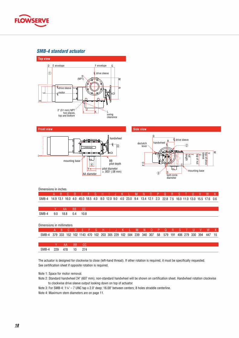
Note 1: Space for motor removal. Note 2: Standard handwheel 24" (607 mm); non-standard handwheel will be shown on certification sheet. Handwheel rotation clockwise
to clockwise drive sleeve output looking down on top of actuator. Note 3: For SMB-4: 1!?4" – 7 UNC tap x 2.0" deep; 16.00" between centers; 8 holes straddle centerline. Note 4: Maximum stem diameters are on page 11.
14.9 13.1 16.0 4.0 45.0 18.5 4.0 8.0 12.0 9.0 4.0 23.0 9.4 13.4 12.1 2.3 22.8 7.5 16.0 11.0 13.0 15.5 17.6 0.6 A B C D E F G H I J K L M N O P Q R S T U V W X
9.0 18.8 0.4 10.8
A B C D E F G H I J K L M N O P Q R S T U V W X
229 478 10 274Y AA BB CC
SMB-4 standard actuator
Front view
C L
C L
C L
C L Limitorque
pilot diameter ± .003" (.08 mm)
CC
BB pilot dept h
Y
AA diameter
mounting base
X
handwheel
4
C L
C L handwheel
T nut lengt h
U top of nut
V top of drive sleeve
W
mounting base S bolt circle diameter
3
O P
R
Q
declutch lever 2
drive sleeve
SMB-4 Standard Actuator T op Vi ew
Side Vi ew Front V ie w
Dimensions in inches
SMB-4
drive sleeve
motor
drive sleeve H
(NPT)
E envelope D
C B
2" (51 mm) NPTtwo places,
top and bottom
J K I L
swing clearance
N M
F envelope G
A
1
Y AA BB CCSMB-4
Dimensions in millimeters
SMB-4 379 333 152 102 1143 470 102 203 305 229 102 584 239 340 307 58 579 191 406 279 330 394 447 15
SMB-4
The actuator is designed for clockwise to close (left-hand thread). If other rotation is required, it must be specifically requested.See certification sheet if opposite rotation is required.
Note 1: Space for motor removal. Note 2: Standard handwheel 24" (607 mm); non-standard handwheel will be shown on certification sheet. Handwheel rotation clockwise
to clockwise drive sleeve output looking down on top of actuator. Note 3: For SMB-4: 1!?4" – 7 UNC tap x 2.0" deep; 16.00" between centers; 8 holes straddle centerline. Note 4: Maximum stem diameters are on page 11.
14.9 13.1 16.0 4.0 45.0 18.5 4.0 8.0 12.0 9.0 4.0 23.0 9.4 13.4 12.1 2.3 22.8 7.5 16.0 11.0 13.0 15.5 17.6 0.6 A B C D E F G H I J K L M N O P Q R S T U V W X
9.0 18.8 0.4 10.8
A B C D E F G H I J K L M N O P Q R S T U V W X
229 478 10 274Y AA BB CC
Side view
C L
C L
C L
C L Limitorque
pilot diameter ± .003" (.08 mm)
CC
BB pilot dept h
Y
AA diameter
mounting base
X
handwheel
4
C L
C L handwheel
T nut lengt h
U top of nut
V top of drive sleeve
W
mounting base S bolt circle diameter
3
O P
R
Q
declutch lever 2
drive sleeve
SMB-4 Standard Actuator T op Vi ew
Side Vi ew Front V ie w
Dimensions in inches
SMB-4
drive sleeve
motor
drive sleeve H
(NPT)
E envelope D
C B
2" (51 mm) NPTtwo places,
top and bottom
J K I L
swing clearance
N M
F envelope G
A
1
Y AA BB CCSMB-4
Dimensions in millimeters
SMB-4 379 333 152 102 1143 470 102 203 305 229 102 584 239 340 307 58 579 191 406 279 330 394 447 15
SMB-4
The actuator is designed for clockwise to close (left-hand thread). If other rotation is required, it must be specifically requested.See certification sheet if opposite rotation is required.
Note 1: Space for motor removal. Note 2: Standard handwheel 24" (607 mm); non-standard handwheel will be shown on certification sheet. Handwheel rotation clockwise
to clockwise drive sleeve output looking down on top of actuator. Note 3: For SMB-4: 1!?4" – 7 UNC tap x 2.0" deep; 16.00" between centers; 8 holes straddle centerline. Note 4: Maximum stem diameters are on page 11.
14.9 13.1 16.0 4.0 45.0 18.5 4.0 8.0 12.0 9.0 4.0 23.0 9.4 13.4 12.1 2.3 22.8 7.5 16.0 11.0 13.0 15.5 17.6 0.6 A B C D E F G H I J K L M N O P Q R S T U V W X
9.0 18.8 0.4 10.8
A B C D E F G H I J K L M N O P Q R S T U V W X
229 478 10 274Y AA BB CC
C L
C L
C L
C L Limitorque
pilot diameter ± .003" (.08 mm)
CC
BB pilot dept h
Y
AA diameter
mounting base
X
handwheel
4
C L
C L handwheel
T nut lengt h
U top of nut
V top of drive sleeve
W
mounting base S bolt circle diameter
3
O P
R
Q
declutch lever 2
drive sleeve
SMB-4 Standard Actuator T op Vi ew
Side Vi ew Front V ie w
Dimensions in inches
SMB-4
drive sleeve
motor
drive sleeve H
(NPT)
E envelope D
C B
2" (51 mm) NPTtwo places,
top and bottom
J K I L
swing clearance
N M
F envelope G
A
1
Y AA BB CCSMB-4
Dimensions in millimeters
SMB-4 379 333 152 102 1143 470 102 203 305 229 102 584 239 340 307 58 579 191 406 279 330 394 447 15
SMB-4
The actuator is designed for clockwise to close (left-hand thread). If other rotation is required, it must be specifically requested.See certification sheet if opposite rotation is required.
Note 1: Space for motor removal. Note 2: Standard handwheel 24" (607 mm); non-standard handwheel will be shown on certification sheet. Handwheel rotation clockwise
to clockwise drive sleeve output looking down on top of actuator. Note 3: For SMB-4: 1!?4" – 7 UNC tap x 2.0" deep; 16.00" between centers; 8 holes straddle centerline. Note 4: Maximum stem diameters are on page 11.
14.9 13.1 16.0 4.0 45.0 18.5 4.0 8.0 12.0 9.0 4.0 23.0 9.4 13.4 12.1 2.3 22.8 7.5 16.0 11.0 13.0 15.5 17.6 0.6 A B C D E F G H I J K L M N O P Q R S T U V W X
9.0 18.8 0.4 10.8
A B C D E F G H I J K L M N O P Q R S T U V W X
229 478 10 274Y AA BB CC
18
Top view
E
.5 I
K
A
H
G2" NPTCONDUITENTRY
B
1CL drive sleeve
CLdrive sleeve
CL motor
C envelope
declutchlever
Jright swing clearance
F(NPT)
D envelope
SMB-5 and SMB-5T standard actuator
Front view
C L
C L
C L
C L
SMB-5 and 5T Standard ActuatorsT op Vi ew Side Vi ew
Front V ie w
Dimensions in inches
SMB-5
SMB-5T
motor
motor
drive sleeve
Limitorque
I
C envelope
H
B
A
G
declutch lever
J right swing clearance
W
V
pilot diameter ± .003" ( ± .08 mm)
2" (51 mm) NPT two places
2" (51 mm) NP T two places
Z mounting base diameter
CC
Y
F (NPT)
K
BB pilot depth
AA
D envelope E
1
drive sleeve
3
X 4
SMB-5
SMB-5T
Dimensions in millimeters
SMB-5
SMB-5T
SMB-5
SMB-5T
The actuator is designed for clockwise to close (left-hand thread). If other rotation is required, it must be specifically requested.See certification sheet if opposite rotation is required.
Note 1: Space for motor removal.Note 2: Standard handwheel 30" (762 mm); non-standard handwheel will be shown on certification sheet. Handwheel rotation clockwise
to clockwise drive sleeve output looking down on top of actuator.
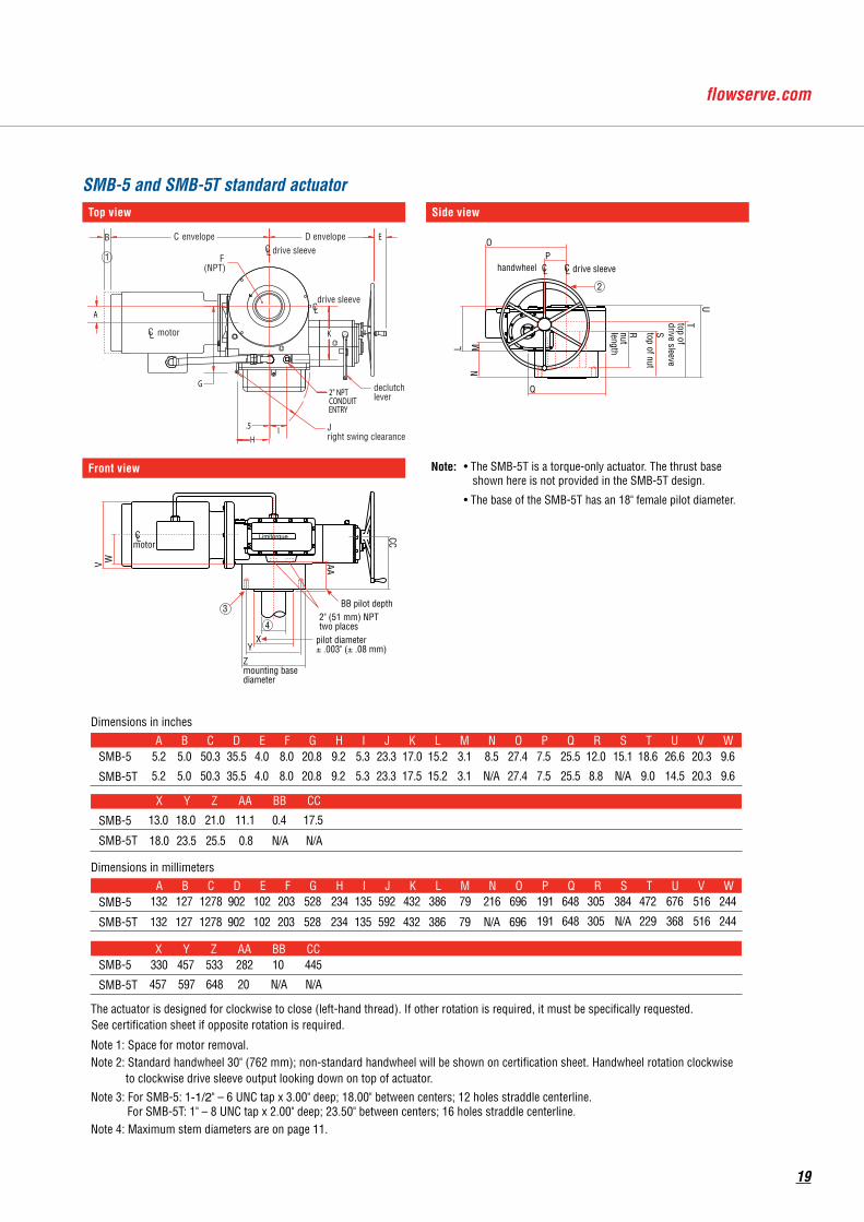
Note 3: For SMB-5: 1-1/2" – 6 UNC tap x 3.00" deep; 18.00" between centers; 12 holes straddle centerline. For SMB-5T: 1" – 8 UNC tap x 2.00" deep; 23.50" between centers; 16 holes straddle centerline.Note 4: Maximum stem diameters are on page 11.
A B C D E F G H I J K L M N O P Q R S T U V W
A B C D E F G H I J K L M N O P Q R S T U V W
X Y Z AA BB CC
X Y Z AA BB CC
7.5 25.5 12.0 15.1 18.6 26.6 20.3 9.65.2 5.0 50.3 35.5 4.0 8.0 20.8 9.2 5.3 23.3 17.0 15.2 3.1 8.5 27.4
7.5 25.5 8.8 N/A 9.0 14.5 20.3 9.65.2 5.0 50.3 35.5 4.0 8.0 20.8 9.2 5.3 23.3 17.5 15.2 3.1 N/A 27.4
13.0 18.0 21.0 11.1 0.4 17.5
18.0 23.5 25.5 0.8 N/A N/A
191 648 305 384 472 676 516 244132 127 1278 902 102 203 528 234 135 592 432 386 79 216 696
191 648 305 N/A 229 368 516 244132 127 1278 902 102 203 528 234 135 592 432 386 79 N/A 696
330 457 533 282 10 445
457 597 648 20 N/A N/A
C L C L handwheel
O
Q
P
M
L
U
R nut length
N
S top of nut
T top of drive sleeve
drive sleeve
2
• The SMB-5T is a torque-only actuator. The thrust base shown here is not provided in the SMB-5T design. • The base of the SMB-5T has an 18" female pilot diameter.
Note:
C L
C L
C L
C L
SMB-5 and 5T Standard ActuatorsT op Vi ew Side Vi ew
Front V ie w
Dimensions in inches
SMB-5
SMB-5T
motor
motor
drive sleeve
Limitorque
I
C envelope
H
B
A
G
declutch lever
J right swing clearance
W
V
pilot diameter ± .003" ( ± .08 mm)
2" (51 mm) NPT two places
2" (51 mm) NP T two places
Z mounting base diameter
CC
Y
F (NPT)
K
BB pilot depth
AA
D envelope E
1
drive sleeve
3
X 4
SMB-5
SMB-5T
Dimensions in millimeters
SMB-5
SMB-5T
SMB-5
SMB-5T
The actuator is designed for clockwise to close (left-hand thread). If other rotation is required, it must be specifically requested.See certification sheet if opposite rotation is required.
Note 1: Space for motor removal.Note 2: Standard handwheel 30" (762 mm); non-standard handwheel will be shown on certification sheet. Handwheel rotation clockwise
to clockwise drive sleeve output looking down on top of actuator.
Note 3: For SMB-5: 1-1/2" – 6 UNC tap x 3.00" deep; 18.00" between centers; 12 holes straddle centerline. For SMB-5T: 1" – 8 UNC tap x 2.00" deep; 23.50" between centers; 16 holes straddle centerline.Note 4: Maximum stem diameters are on page 11.
A B C D E F G H I J K L M N O P Q R S T U V W
A B C D E F G H I J K L M N O P Q R S T U V W
X Y Z AA BB CC
X Y Z AA BB CC
7.5 25.5 12.0 15.1 18.6 26.6 20.3 9.65.2 5.0 50.3 35.5 4.0 8.0 20.8 9.2 5.3 23.3 17.0 15.2 3.1 8.5 27.4
7.5 25.5 8.8 N/A 9.0 14.5 20.3 9.65.2 5.0 50.3 35.5 4.0 8.0 20.8 9.2 5.3 23.3 17.5 15.2 3.1 N/A 27.4
13.0 18.0 21.0 11.1 0.4 17.5
18.0 23.5 25.5 0.8 N/A N/A
191 648 305 384 472 676 516 244132 127 1278 902 102 203 528 234 135 592 432 386 79 216 696
191 648 305 N/A 229 368 516 244132 127 1278 902 102 203 528 234 135 592 432 386 79 N/A 696
330 457 533 282 10 445
457 597 648 20 N/A N/A
C L C L handwheel
O
Q
P
M
L
U
R nut length
N
S top of nut
T top of drive sleeve
drive sleeve
2
• The SMB-5T is a torque-only actuator. The thrust base shown here is not provided in the SMB-5T design. • The base of the SMB-5T has an 18" female pilot diameter.
Note:
Side view
C L
C L
C L
C L
SMB-5 and 5T Standard ActuatorsT op Vi ew Side Vi ew
Front V ie w
Dimensions in inches
SMB-5
SMB-5T
motor
motor
drive sleeve
Limitorque
I
C envelope
H
B
A
G
declutch lever
J right swing clearance
W
V
pilot diameter ± .003" ( ± .08 mm)
2" (51 mm) NPT two places
2" (51 mm) NP T two places
Z mounting base diameter
CC
Y
F (NPT)
K
BB pilot depth
AA
D envelope E
1
drive sleeve
3
X 4
SMB-5
SMB-5T
Dimensions in millimeters
SMB-5
SMB-5T
SMB-5
SMB-5T
The actuator is designed for clockwise to close (left-hand thread). If other rotation is required, it must be specifically requested.See certification sheet if opposite rotation is required.
Note 1: Space for motor removal.Note 2: Standard handwheel 30" (762 mm); non-standard handwheel will be shown on certification sheet. Handwheel rotation clockwise
to clockwise drive sleeve output looking down on top of actuator.
Note 3: For SMB-5: 1-1/2" – 6 UNC tap x 3.00" deep; 18.00" between centers; 12 holes straddle centerline. For SMB-5T: 1" – 8 UNC tap x 2.00" deep; 23.50" between centers; 16 holes straddle centerline.Note 4: Maximum stem diameters are on page 11.
A B C D E F G H I J K L M N O P Q R S T U V W
A B C D E F G H I J K L M N O P Q R S T U V W
X Y Z AA BB CC
X Y Z AA BB CC
7.5 25.5 12.0 15.1 18.6 26.6 20.3 9.65.2 5.0 50.3 35.5 4.0 8.0 20.8 9.2 5.3 23.3 17.0 15.2 3.1 8.5 27.4
7.5 25.5 8.8 N/A 9.0 14.5 20.3 9.65.2 5.0 50.3 35.5 4.0 8.0 20.8 9.2 5.3 23.3 17.5 15.2 3.1 N/A 27.4
13.0 18.0 21.0 11.1 0.4 17.5
18.0 23.5 25.5 0.8 N/A N/A
191 648 305 384 472 676 516 244132 127 1278 902 102 203 528 234 135 592 432 386 79 216 696
191 648 305 N/A 229 368 516 244132 127 1278 902 102 203 528 234 135 592 432 386 79 N/A 696
330 457 533 282 10 445
457 597 648 20 N/A N/A
C L C L handwheel
O
Q
P
M
L
U
R nut length
N
S top of nut
T top of drive sleeve
drive sleeve
2
• The SMB-5T is a torque-only actuator. The thrust base shown here is not provided in the SMB-5T design. • The base of the SMB-5T has an 18" female pilot diameter.
Note:
19
Top view
C L
C L
C L
C L
C L C L
2" (51 mm) NPT 2 places
4
SMB-5XT Standard Actuator T op Vi ew
Side Vi ew Front V ie w
Dimensions in inches
SMB-5XT
motor
drive sleeve
handwheel
Limitorque
handwheel
2" (51 mm) NPT two places
DD diameter 3
declutch lever
E envelope
I H
F
G
D envelope C
B A
J L right swing clearance
W d
iam
eter
env
elop
e X
Y Z A A
BB diameter between centers
CC mounting base diameter
EE
N M
O
P Q
R S
V T
U
drive sleeve
1
motor
2
Dimensions in millimeters
SMB-5XT
The actuator is designed for clockwise to close (left-hand thread). If other rotation is required, it must be specifically requested.See certification sheet if opposite rotation is required.
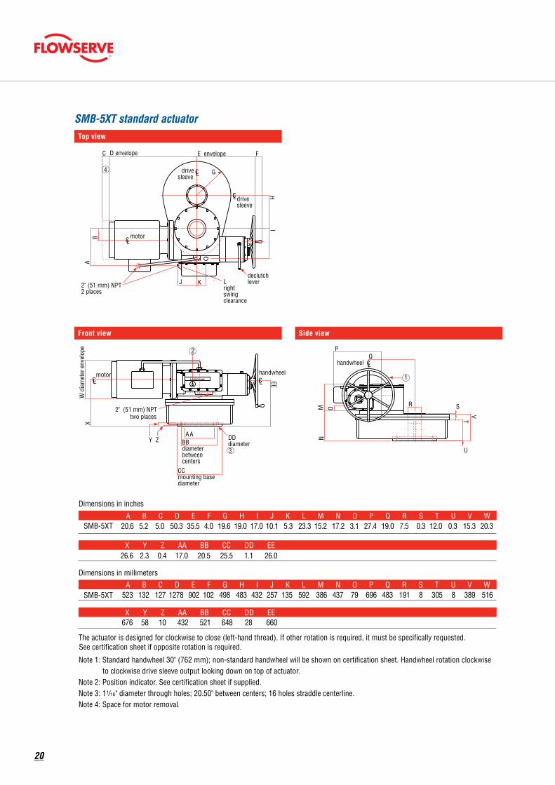
Note 1: Standard handwheel 30" (762 mm); non-standard handwheel will be shown on certification sheet. Handwheel rotation clockwiseto clockwise drive sleeve output looking down on top of actuator.
Note 2: Position indicator. See certification sheet if supplied.Note 3: 1!?16" diameter through holes; 20.50" between centers; 16 holes straddle centerline.Note 4: Space for motor removal.
A B C D E F G H I J K L M N O P Q R S T U V W
A B C D E F G H I J K L M N O P Q R S T U V W
X Y Z AA BB CC DD EE
X Y Z AA BB CC DD EE
20.6 5.2 5.0 50.3 35.5 4.0 19.6 19.0 17.0 10.1 5.3 23.3 15.2 17.2 3.1 27.4 19.0 7.5 0.3 12.0 0.3 15.3 20.3
26.6 2.3 0.4 17.0 20.5 25.5 1.1 26.0
523 132 127 1278 902 102 498 483 432 257 135 592 386 437 79 696 483 191 8 305 8 389 516
676 58 10 432 521 648 28 660
K
SMB-5XT standard actuator
Front view
C L
C L
C L
C L
C L C L
2" (51 mm) NPT 2 places
4
SMB-5XT Standard Actuator T op Vi ew
Side Vi ew Front V ie w
Dimensions in inches
SMB-5XT
motor
drive sleeve
handwheel
Limitorque
handwheel
2" (51 mm) NPT two places
DD diameter 3
declutch lever
E envelope
I H
F
G
D envelope C
B A
J L right swing clearance
W d
iam
eter
env
elop
e X
Y Z A A
BB diameter between centers
CC mounting base diameter
EE
N M
O
P Q
R S
V T
U
drive sleeve
1
motor
2
Dimensions in millimeters
SMB-5XT
The actuator is designed for clockwise to close (left-hand thread). If other rotation is required, it must be specifically requested.See certification sheet if opposite rotation is required.
Note 1: Standard handwheel 30" (762 mm); non-standard handwheel will be shown on certification sheet. Handwheel rotation clockwiseto clockwise drive sleeve output looking down on top of actuator.
Note 2: Position indicator. See certification sheet if supplied.Note 3: 1!?16" diameter through holes; 20.50" between centers; 16 holes straddle centerline.Note 4: Space for motor removal.
A B C D E F G H I J K L M N O P Q R S T U V W
A B C D E F G H I J K L M N O P Q R S T U V W
X Y Z AA BB CC DD EE
X Y Z AA BB CC DD EE
20.6 5.2 5.0 50.3 35.5 4.0 19.6 19.0 17.0 10.1 5.3 23.3 15.2 17.2 3.1 27.4 19.0 7.5 0.3 12.0 0.3 15.3 20.3
26.6 2.3 0.4 17.0 20.5 25.5 1.1 26.0
523 132 127 1278 902 102 498 483 432 257 135 592 386 437 79 696 483 191 8 305 8 389 516
676 58 10 432 521 648 28 660
K
Side view
C L
C L
C L
C L
C L C L
2" (51 mm) NPT 2 places
4
SMB-5XT Standard Actuator T op Vi ew
Side Vi ew Front V ie w
Dimensions in inches
SMB-5XT
motor
drive sleeve
handwheel
Limitorque
handwheel
2" (51 mm) NPT two places
DD diameter 3
declutch lever
E envelope
I H
F
G
D envelope C
B A
J L right swing clearance
W d
iam
eter
env
elop
e X
Y Z A A
BB diameter between centers
CC mounting base diameter
EE
N M
O
P Q
R S
V T
U
drive sleeve
1
motor
2
Dimensions in millimeters
SMB-5XT
The actuator is designed for clockwise to close (left-hand thread). If other rotation is required, it must be specifically requested.See certification sheet if opposite rotation is required.
Note 1: Standard handwheel 30" (762 mm); non-standard handwheel will be shown on certification sheet. Handwheel rotation clockwiseto clockwise drive sleeve output looking down on top of actuator.
Note 2: Position indicator. See certification sheet if supplied.Note 3: 1!?16" diameter through holes; 20.50" between centers; 16 holes straddle centerline.Note 4: Space for motor removal.
A B C D E F G H I J K L M N O P Q R S T U V W
A B C D E F G H I J K L M N O P Q R S T U V W
X Y Z AA BB CC DD EE
X Y Z AA BB CC DD EE
20.6 5.2 5.0 50.3 35.5 4.0 19.6 19.0 17.0 10.1 5.3 23.3 15.2 17.2 3.1 27.4 19.0 7.5 0.3 12.0 0.3 15.3 20.3
26.6 2.3 0.4 17.0 20.5 25.5 1.1 26.0
523 132 127 1278 902 102 498 483 432 257 135 592 386 437 79 696 483 191 8 305 8 389 516
676 58 10 432 521 648 28 660
K C L
C L
C L
C L
C L C L
2" (51 mm) NPT 2 places
4
SMB-5XT Standard Actuator T op Vi ew
Side Vi ew Front V ie w
Dimensions in inches
SMB-5XT
motor
drive sleeve
handwheel
Limitorque
handwheel
2" (51 mm) NPT two places
DD diameter 3
declutch lever
E envelope
I H
F
G
D envelope C
B A
J L right swing clearance
W d
iam
eter
env
elop
e X
Y Z A A
BB diameter between centers
CC mounting base diameter
EE
N M
O
P Q
R S
V T
U
drive sleeve
1
motor
2
Dimensions in millimeters
SMB-5XT
The actuator is designed for clockwise to close (left-hand thread). If other rotation is required, it must be specifically requested.See certification sheet if opposite rotation is required.
Note 1: Standard handwheel 30" (762 mm); non-standard handwheel will be shown on certification sheet. Handwheel rotation clockwiseto clockwise drive sleeve output looking down on top of actuator.
Note 2: Position indicator. See certification sheet if supplied.Note 3: 1!?16" diameter through holes; 20.50" between centers; 16 holes straddle centerline.Note 4: Space for motor removal.
A B C D E F G H I J K L M N O P Q R S T U V W
A B C D E F G H I J K L M N O P Q R S T U V W
X Y Z AA BB CC DD EE
X Y Z AA BB CC DD EE
20.6 5.2 5.0 50.3 35.5 4.0 19.6 19.0 17.0 10.1 5.3 23.3 15.2 17.2 3.1 27.4 19.0 7.5 0.3 12.0 0.3 15.3 20.3
26.6 2.3 0.4 17.0 20.5 25.5 1.1 26.0
523 132 127 1278 902 102 498 483 432 257 135 592 386 437 79 696 483 191 8 305 8 389 516
676 58 10 432 521 648 28 660
K
20
Top view
L C L C
L C
L C
L C
L C
SB-00 Standard Actuator T op Vi ew
Side Vi ew Front V ie w
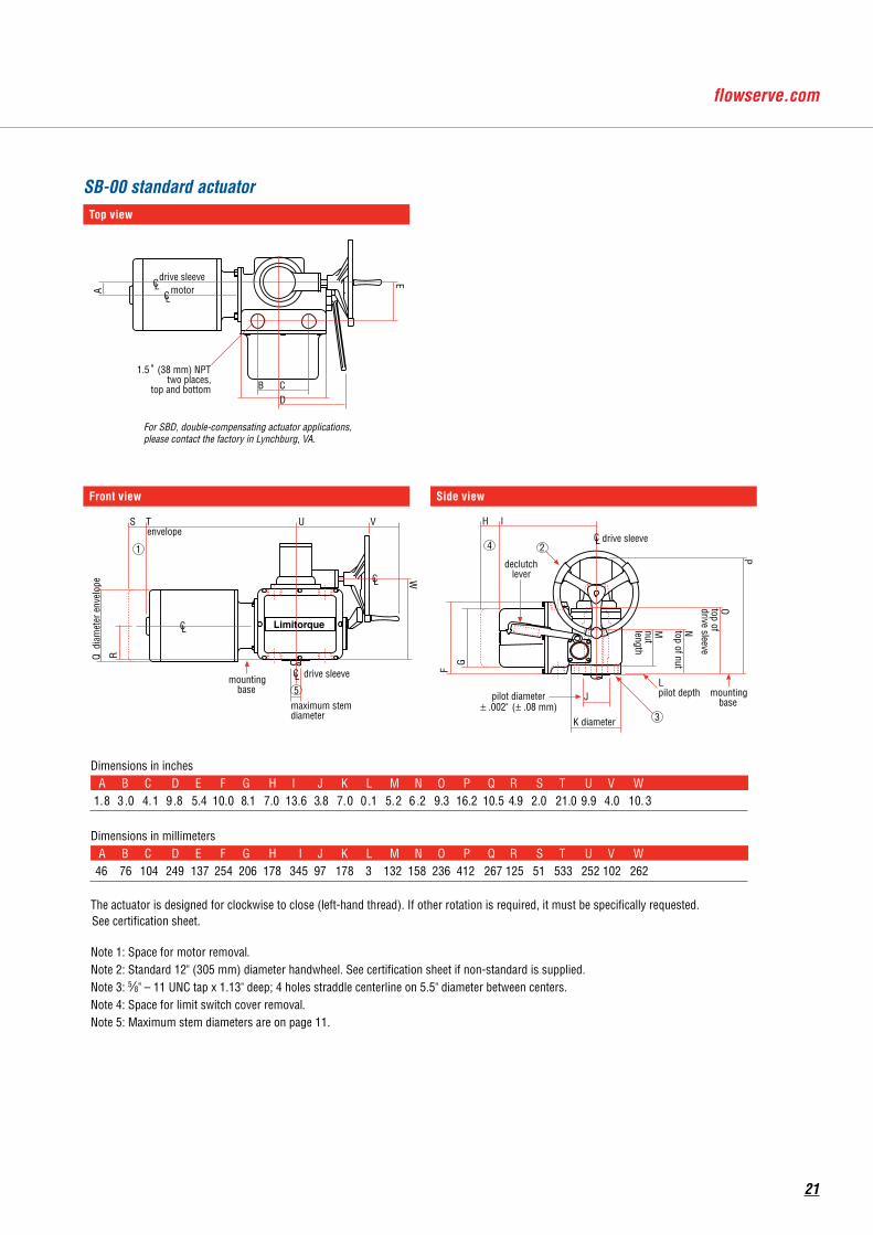
Dimensions in inchesA B C D E F G H I J K L M N O P Q R S T U V W
1. 8 3 .0 4. 1 9 .8 5.4 10. 0 8 .1 7.0 13. 6 3 .8 7. 0 0 .1 5. 2 6 .2 9.3 16.2 10. 5 4 .9 2.0 21. 0 9 .9 4.0 10. 3
The actuator is designed for clockwise to close (left-hand thread). If other rotation is required, it must be specifically requested.See certification sheet.
Note 1: Space for motor removal . Note 2: Standard 12" (305 mm) diameter handwheel. See certification sheet if non-standard is supplied. Note 3: 5∕8" – 11 UNC tap x 1.13" deep; 4 holes straddle centerline on 5.5" diameter between centers.Note 4: Space for limit switch cover removal . Note 5: Maximum stem diameters are on page 11.
Limitorque
motor drive sleeve
1.5 " (38 mm) NPT two places,
top and bottom
declutch lever
mounting base
A
E
B
L pilot depth
C D
F
G
H I
drive sleeve 4
K diameter
J
2
P
O top of drive sleeve
N top of nut
M
nut length
3
pilot diameter ± .002" ( ± .08 mm)
S T envelope
U V
Q d
iam
eter
env
elop
e
R
drive sleeve
5 maximum stem diameter
mounting base
W
Dimensions in millimetersA B C D E F G H I J K L M N O P Q R S T U V W
46 76 104 249 137 254 206 178 345 97 178 3 132 158 236 412 267 125 51 533 252 102 262
1
For SBD, double-compensating actuator applications, please contact the factory in Lynchburg, VA.
SB-00 standard actuator
Front view
L C L C
L C
L C
L C
L C
SB-00 Standard Actuator T op Vi ew
Side Vi ew Front V ie w
Dimensions in inchesA B C D E F G H I J K L M N O P Q R S T U V W
1. 8 3 .0 4. 1 9 .8 5.4 10. 0 8 .1 7.0 13. 6 3 .8 7. 0 0 .1 5. 2 6 .2 9.3 16.2 10. 5 4 .9 2.0 21. 0 9 .9 4.0 10. 3
The actuator is designed for clockwise to close (left-hand thread). If other rotation is required, it must be specifically requested.See certification sheet.
Note 1: Space for motor removal . Note 2: Standard 12" (305 mm) diameter handwheel. See certification sheet if non-standard is supplied. Note 3: 5∕8" – 11 UNC tap x 1.13" deep; 4 holes straddle centerline on 5.5" diameter between centers.Note 4: Space for limit switch cover removal . Note 5: Maximum stem diameters are on page 11.
Limitorque
motor drive sleeve
1.5 " (38 mm) NPT two places,
top and bottom
declutch lever
mounting base
A
E
B
L pilot depth
C D
F
G
H I
drive sleeve 4
K diameter
J
2
P
O top of drive sleeve
N top of nut
M
nut length
3
pilot diameter ± .002" ( ± .08 mm)
S T envelope
U V
Q d
iam
eter
env
elop
e
R
drive sleeve
5 maximum stem diameter
mounting base
W
Dimensions in millimetersA B C D E F G H I J K L M N O P Q R S T U V W
46 76 104 249 137 254 206 178 345 97 178 3 132 158 236 412 267 125 51 533 252 102 262
1
For SBD, double-compensating actuator applications, please contact the factory in Lynchburg, VA.
Side view
L C L C
L C
L C
L C
L C
SB-00 Standard Actuator T op Vi ew
Side Vi ew Front V ie w
Dimensions in inchesA B C D E F G H I J K L M N O P Q R S T U V W
1. 8 3 .0 4. 1 9 .8 5.4 10. 0 8 .1 7.0 13. 6 3 .8 7. 0 0 .1 5. 2 6 .2 9.3 16.2 10. 5 4 .9 2.0 21. 0 9 .9 4.0 10. 3
The actuator is designed for clockwise to close (left-hand thread). If other rotation is required, it must be specifically requested.See certification sheet.
Note 1: Space for motor removal . Note 2: Standard 12" (305 mm) diameter handwheel. See certification sheet if non-standard is supplied. Note 3: 5∕8" – 11 UNC tap x 1.13" deep; 4 holes straddle centerline on 5.5" diameter between centers.Note 4: Space for limit switch cover removal . Note 5: Maximum stem diameters are on page 11.
Limitorque
motor drive sleeve
1.5 " (38 mm) NPT two places,
top and bottom
declutch lever
mounting base
A
E
B
L pilot depth
C D
F
G
H I
drive sleeve 4
K diameter
J
2
P
O top of drive sleeve
N top of nut
M
nut length
3
pilot diameter ± .002" ( ± .08 mm)
S T envelope
U V
Q d
iam
eter
env
elop
e
R
drive sleeve
5 maximum stem diameter
mounting base
W
Dimensions in millimetersA B C D E F G H I J K L M N O P Q R S T U V W
46 76 104 249 137 254 206 178 345 97 178 3 132 158 236 412 267 125 51 533 252 102 262
1
For SBD, double-compensating actuator applications, please contact the factory in Lynchburg, VA.
21
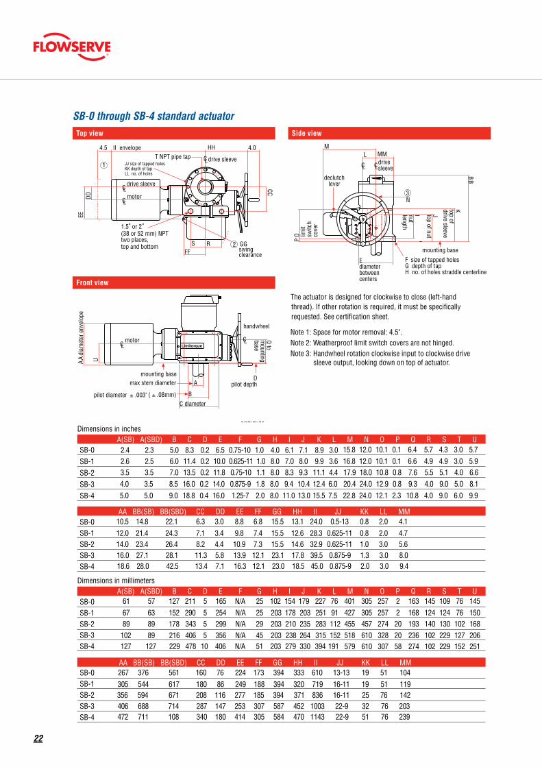
Top view
C L
C L
C L
C L
C L
max stem diameter
pilot diameter ± .003" ( ± .08mm)
C L
C L
SB-0 through 4 Standard Actuators
T op Vi ew
Side Vi ew Front V ie w
Dimensions in inches
SB-0 SB-1SB-2SB-3SB-4
SB-0SB-1SB-2SB-3SB-4
drive sleeve
Limitorque
motor
D pilot depth
mounting base
F size of t apped holes G depth of t ap H no. of holes straddle centerline
E diameter between centers
C diameter
B
Q to m
ounting base
3 N
T NPT pipe t ap
CC
S R FF
DD
EE
II envelope 4.5 HH 4.0
U A A
diam
eter
env
elop
e
O limit
switc
h co
ver
P
I nut length
J top of nut
K top of drive sleeve
M L
declutch lever
MM
1.5 " or 2 " (38 or 52 mm) NPT two places, top and bottom
JJ size of tapped holes KK depth of tap LL no. of holes
A
B B
2 GG swing clearance
1 drive sleeve
drive sleeve
motor
handwheel
Dimensions in millimeters
SB-0SB-1SB-2SB-3SB-4
SB-0SB-1SB-2SB-3SB-4
mounting base
The actuator is designed for clockwise to close (left-handthread). If other rotation is required, it must be specifically requested. See certification sheet.
Note 1: Space for motor removal: 4.5". Note 2: W eatherproof limit switch covers are not hinged. Note 3: Handwheel rotation clockwise input to clockwise drive
sleeve output, looking down on top of actuator.
A(SB) A(SBD) B C D E F G H I J K L M N O P Q R S T U 2.4 2.3 5.0 8.3 0.2 6.5 0.75-10 1.0 4.0 6.1 7.1 8.9 3.0 15.8 12.0 10.1 0.1 6.4 5.7 4.3 3.0 5.7
16.8 12.0 10.1 0.1 6.6 4.9 4.9 3.0 5.92.6 2.5 6.0 11.4 0.2 10.0 0.625-11 1.0 8.0 7.0 8.0 9.9 3.63.5 3.5 7.0 13.5 0.2 11.8 0.75-10 1.1 8.0 8.3 9.3 11.1 4.4 17.9 18.0 10.8 0.8 7.6 5.5 5.1 4.0 6.6
20.4 24.0 12.9 0.8 9.3 4.0 9.0 5.0 8.14.0 3.5 8.5 16.0 0.2 14.0 0.875-9 1.8 8.0 9.4 10.4 12.4 6.0
AA BB(SB) BB(SBD) CC DD EE FF GG HH II JJ KK LL MM
5.0 5.0 9.0 18.8 0.4 16.0 1.25-7 2.0 8.0 11.0 13.0 15.5 7.5 22.8 24.0 12.1 2.3 10.8 4.0 9.0 6.0 9.9
10.5 14.8 22.1 6.3 3.0 8.8 6.8 15.5 13.1 24.0 0.5-13 0.8 2.0 4.112.0 21.4 24.3 7.1 3.4 9.8 7.4 15.5 12.6 28.3 0.625-11 0.8 2.0 4.714.0 23.4 26.4 8.2 4.4 10.9 7.3 15.5 14.6 32.9 0.625-11 1.0 3.0 5.616.0 27.1 28.1 11.3 5.8 13.9 12.1 23.1 17.8 39.5 0.875-9 1.3 3.0 8.018.6 28.0 42.5 13.4 7.1 16.3 12.1 23.0 18.5 45.0 0.875-9 2.0 3.0 9.4
A(SB) A(SBD) B C D E F G H I J K L M N O P Q R S T U61 57 127 211 5 165 N/A 25 102 154 179 227 76 401 305 257 2 163 145 109 76 14567 63 152 290 5 254 N/A 25 203 178 203 251 91 427 305 257 2 168 124 124 76 15089 89 178 343 5 299 N/A 29 203 210 235 283 112 455 457 274 20 193 140 130 102 168
518 610 328 20 236 102 229 127 206102 89 216 406 5 356 N/A 45 203 238 264 315 152127 127 229 478 10 406 N/A 51 203 279 330 394 191 579 610 307 58 274 102 229 152 251
AA BB(SB) BB(SBD) CC DD EE FF GG HH II JJ KK LL MM267 376 561 160 76 224 173 394 333 610 13-13 19 51 104305 544 617 180 86 249 188 394 320 719 16-11 19 51 119356 594 671 208 116 277 185 394 371 836 16-11 25 76 142406 688 714 287 147 253 307 587 452 1003 22-9 32 76 203472 711 108 340 180 414 305 584 470 1143 22-9 51 76 239
SB-0 through SB-4 standard actuator
Front view
C L
C L
C L
C L
C L
max stem diameter
pilot diameter ± .003" ( ± .08mm)
C L
C L
SB-0 through 4 Standard Actuators
T op Vi ew
Side Vi ew Front V ie w
Dimensions in inches
SB-0 SB-1SB-2SB-3SB-4
SB-0SB-1SB-2SB-3SB-4
drive sleeve
Limitorque
motor
D pilot depth
mounting base
F size of t apped holes G depth of t ap H no. of holes straddle centerline
E diameter between centers
C diameter
B
Q to m
ounting base
3 N
T NPT pipe t ap
CC
S R FF
DD
EE
II envelope 4.5 HH 4.0
U A A
diam
eter
env
elop
e
O limit
switc
h co
ver
P
I nut length
J top of nut
K top of drive sleeve
M L
declutch lever
MM
1.5 " or 2 " (38 or 52 mm) NPT two places, top and bottom
JJ size of tapped holes KK depth of tap LL no. of holes
A
B B
2 GG swing clearance
1 drive sleeve
drive sleeve
motor
handwheel
Dimensions in millimeters
SB-0SB-1SB-2SB-3SB-4
SB-0SB-1SB-2SB-3SB-4
mounting base
The actuator is designed for clockwise to close (left-handthread). If other rotation is required, it must be specifically requested. See certification sheet.
Note 1: Space for motor removal: 4.5". Note 2: W eatherproof limit switch covers are not hinged. Note 3: Handwheel rotation clockwise input to clockwise drive
sleeve output, looking down on top of actuator.
A(SB) A(SBD) B C D E F G H I J K L M N O P Q R S T U 2.4 2.3 5.0 8.3 0.2 6.5 0.75-10 1.0 4.0 6.1 7.1 8.9 3.0 15.8 12.0 10.1 0.1 6.4 5.7 4.3 3.0 5.7
16.8 12.0 10.1 0.1 6.6 4.9 4.9 3.0 5.92.6 2.5 6.0 11.4 0.2 10.0 0.625-11 1.0 8.0 7.0 8.0 9.9 3.63.5 3.5 7.0 13.5 0.2 11.8 0.75-10 1.1 8.0 8.3 9.3 11.1 4.4 17.9 18.0 10.8 0.8 7.6 5.5 5.1 4.0 6.6
20.4 24.0 12.9 0.8 9.3 4.0 9.0 5.0 8.14.0 3.5 8.5 16.0 0.2 14.0 0.875-9 1.8 8.0 9.4 10.4 12.4 6.0
AA BB(SB) BB(SBD) CC DD EE FF GG HH II JJ KK LL MM
5.0 5.0 9.0 18.8 0.4 16.0 1.25-7 2.0 8.0 11.0 13.0 15.5 7.5 22.8 24.0 12.1 2.3 10.8 4.0 9.0 6.0 9.9
10.5 14.8 22.1 6.3 3.0 8.8 6.8 15.5 13.1 24.0 0.5-13 0.8 2.0 4.112.0 21.4 24.3 7.1 3.4 9.8 7.4 15.5 12.6 28.3 0.625-11 0.8 2.0 4.714.0 23.4 26.4 8.2 4.4 10.9 7.3 15.5 14.6 32.9 0.625-11 1.0 3.0 5.616.0 27.1 28.1 11.3 5.8 13.9 12.1 23.1 17.8 39.5 0.875-9 1.3 3.0 8.018.6 28.0 42.5 13.4 7.1 16.3 12.1 23.0 18.5 45.0 0.875-9 2.0 3.0 9.4
A(SB) A(SBD) B C D E F G H I J K L M N O P Q R S T U61 57 127 211 5 165 N/A 25 102 154 179 227 76 401 305 257 2 163 145 109 76 14567 63 152 290 5 254 N/A 25 203 178 203 251 91 427 305 257 2 168 124 124 76 15089 89 178 343 5 299 N/A 29 203 210 235 283 112 455 457 274 20 193 140 130 102 168
518 610 328 20 236 102 229 127 206102 89 216 406 5 356 N/A 45 203 238 264 315 152127 127 229 478 10 406 N/A 51 203 279 330 394 191 579 610 307 58 274 102 229 152 251
AA BB(SB) BB(SBD) CC DD EE FF GG HH II JJ KK LL MM267 376 561 160 76 224 173 394 333 610 13-13 19 51 104305 544 617 180 86 249 188 394 320 719 16-11 19 51 119356 594 671 208 116 277 185 394 371 836 16-11 25 76 142406 688 714 287 147 253 307 587 452 1003 22-9 32 76 203472 711 108 340 180 414 305 584 470 1143 22-9 51 76 239
Side view
C L
C L
C L
C L
C L
max stem diameter
pilot diameter ± .003" ( ± .08mm)
C L
C L
SB-0 through 4 Standard Actuators
T op Vi ew
Side Vi ew Front V ie w
Dimensions in inches
SB-0 SB-1SB-2SB-3SB-4
SB-0SB-1SB-2SB-3SB-4
drive sleeve
Limitorque
motor
D pilot depth
mounting base
F size of t apped holes G depth of t ap H no. of holes straddle centerline
E diameter between centers
C diameter
B
Q to m
ounting base
3 N
T NPT pipe t ap
CC
S R FF
DD
EE
II envelope 4.5 HH 4.0
U A A
diam
eter
env
elop
e
O limit
switc
h co
ver
P
I nut length
J top of nut
K top of drive sleeve
M L
declutch lever
MM
1.5 " or 2 " (38 or 52 mm) NPT two places, top and bottom
JJ size of tapped holes KK depth of tap LL no. of holes
A
B B
2 GG swing clearance
1 drive sleeve
drive sleeve
motor
handwheel
Dimensions in millimeters
SB-0SB-1SB-2SB-3SB-4
SB-0SB-1SB-2SB-3SB-4
mounting base
The actuator is designed for clockwise to close (left-handthread). If other rotation is required, it must be specifically requested. See certification sheet.
Note 1: Space for motor removal: 4.5". Note 2: W eatherproof limit switch covers are not hinged. Note 3: Handwheel rotation clockwise input to clockwise drive
sleeve output, looking down on top of actuator.
A(SB) A(SBD) B C D E F G H I J K L M N O P Q R S T U 2.4 2.3 5.0 8.3 0.2 6.5 0.75-10 1.0 4.0 6.1 7.1 8.9 3.0 15.8 12.0 10.1 0.1 6.4 5.7 4.3 3.0 5.7
16.8 12.0 10.1 0.1 6.6 4.9 4.9 3.0 5.92.6 2.5 6.0 11.4 0.2 10.0 0.625-11 1.0 8.0 7.0 8.0 9.9 3.63.5 3.5 7.0 13.5 0.2 11.8 0.75-10 1.1 8.0 8.3 9.3 11.1 4.4 17.9 18.0 10.8 0.8 7.6 5.5 5.1 4.0 6.6
20.4 24.0 12.9 0.8 9.3 4.0 9.0 5.0 8.14.0 3.5 8.5 16.0 0.2 14.0 0.875-9 1.8 8.0 9.4 10.4 12.4 6.0
AA BB(SB) BB(SBD) CC DD EE FF GG HH II JJ KK LL MM
5.0 5.0 9.0 18.8 0.4 16.0 1.25-7 2.0 8.0 11.0 13.0 15.5 7.5 22.8 24.0 12.1 2.3 10.8 4.0 9.0 6.0 9.9
10.5 14.8 22.1 6.3 3.0 8.8 6.8 15.5 13.1 24.0 0.5-13 0.8 2.0 4.112.0 21.4 24.3 7.1 3.4 9.8 7.4 15.5 12.6 28.3 0.625-11 0.8 2.0 4.714.0 23.4 26.4 8.2 4.4 10.9 7.3 15.5 14.6 32.9 0.625-11 1.0 3.0 5.616.0 27.1 28.1 11.3 5.8 13.9 12.1 23.1 17.8 39.5 0.875-9 1.3 3.0 8.018.6 28.0 42.5 13.4 7.1 16.3 12.1 23.0 18.5 45.0 0.875-9 2.0 3.0 9.4
A(SB) A(SBD) B C D E F G H I J K L M N O P Q R S T U61 57 127 211 5 165 N/A 25 102 154 179 227 76 401 305 257 2 163 145 109 76 14567 63 152 290 5 254 N/A 25 203 178 203 251 91 427 305 257 2 168 124 124 76 15089 89 178 343 5 299 N/A 29 203 210 235 283 112 455 457 274 20 193 140 130 102 168
518 610 328 20 236 102 229 127 206102 89 216 406 5 356 N/A 45 203 238 264 315 152127 127 229 478 10 406 N/A 51 203 279 330 394 191 579 610 307 58 274 102 229 152 251
AA BB(SB) BB(SBD) CC DD EE FF GG HH II JJ KK LL MM267 376 561 160 76 224 173 394 333 610 13-13 19 51 104305 544 617 180 86 249 188 394 320 719 16-11 19 51 119356 594 671 208 116 277 185 394 371 836 16-11 25 76 142406 688 714 287 147 253 307 587 452 1003 22-9 32 76 203472 711 108 340 180 414 305 584 470 1143 22-9 51 76 239
C L
C L
C L
C L
C L
max stem diameter
pilot diameter ± .003" ( ± .08mm)
C L
C L
SB-0 through 4 Standard Actuators
T op Vi ew
Side Vi ew Front V ie w
Dimensions in inches
SB-0 SB-1SB-2SB-3SB-4
SB-0SB-1SB-2SB-3SB-4
drive sleeve
Limitorque
motor
D pilot depth
mounting base
F size of t apped holes G depth of t ap H no. of holes straddle centerline
E diameter between centers
C diameter
B Q to m
ounting base
3 N
T NPT pipe t ap
CC
S R FF
DD
EE
II envelope 4.5 HH 4.0
U A A
diam
eter
env
elop
e
O limit
switc
h co
ver
P
I nut length
J top of nut
K top of drive sleeve
M L
declutch lever
MM
1.5 " or 2 " (38 or 52 mm) NPT two places, top and bottom
JJ size of tapped holes KK depth of tap LL no. of holes
A
B B
2 GG swing clearance
1 drive sleeve
drive sleeve
motor
handwheel
Dimensions in millimeters
SB-0SB-1SB-2SB-3SB-4
SB-0SB-1SB-2SB-3SB-4
mounting base
The actuator is designed for clockwise to close (left-handthread). If other rotation is required, it must be specifically requested. See certification sheet.
Note 1: Space for motor removal: 4.5". Note 2: W eatherproof limit switch covers are not hinged. Note 3: Handwheel rotation clockwise input to clockwise drive
sleeve output, looking down on top of actuator.
A(SB) A(SBD) B C D E F G H I J K L M N O P Q R S T U 2.4 2.3 5.0 8.3 0.2 6.5 0.75-10 1.0 4.0 6.1 7.1 8.9 3.0 15.8 12.0 10.1 0.1 6.4 5.7 4.3 3.0 5.7
16.8 12.0 10.1 0.1 6.6 4.9 4.9 3.0 5.92.6 2.5 6.0 11.4 0.2 10.0 0.625-11 1.0 8.0 7.0 8.0 9.9 3.63.5 3.5 7.0 13.5 0.2 11.8 0.75-10 1.1 8.0 8.3 9.3 11.1 4.4 17.9 18.0 10.8 0.8 7.6 5.5 5.1 4.0 6.6
20.4 24.0 12.9 0.8 9.3 4.0 9.0 5.0 8.14.0 3.5 8.5 16.0 0.2 14.0 0.875-9 1.8 8.0 9.4 10.4 12.4 6.0
AA BB(SB) BB(SBD) CC DD EE FF GG HH II JJ KK LL MM
5.0 5.0 9.0 18.8 0.4 16.0 1.25-7 2.0 8.0 11.0 13.0 15.5 7.5 22.8 24.0 12.1 2.3 10.8 4.0 9.0 6.0 9.9
10.5 14.8 22.1 6.3 3.0 8.8 6.8 15.5 13.1 24.0 0.5-13 0.8 2.0 4.112.0 21.4 24.3 7.1 3.4 9.8 7.4 15.5 12.6 28.3 0.625-11 0.8 2.0 4.714.0 23.4 26.4 8.2 4.4 10.9 7.3 15.5 14.6 32.9 0.625-11 1.0 3.0 5.616.0 27.1 28.1 11.3 5.8 13.9 12.1 23.1 17.8 39.5 0.875-9 1.3 3.0 8.018.6 28.0 42.5 13.4 7.1 16.3 12.1 23.0 18.5 45.0 0.875-9 2.0 3.0 9.4
A(SB) A(SBD) B C D E F G H I J K L M N O P Q R S T U61 57 127 211 5 165 N/A 25 102 154 179 227 76 401 305 257 2 163 145 109 76 14567 63 152 290 5 254 N/A 25 203 178 203 251 91 427 305 257 2 168 124 124 76 15089 89 178 343 5 299 N/A 29 203 210 235 283 112 455 457 274 20 193 140 130 102 168
518 610 328 20 236 102 229 127 206102 89 216 406 5 356 N/A 45 203 238 264 315 152127 127 229 478 10 406 N/A 51 203 279 330 394 191 579 610 307 58 274 102 229 152 251
AA BB(SB) BB(SBD) CC DD EE FF GG HH II JJ KK LL MM267 376 561 160 76 224 173 394 333 610 13-13 19 51 104305 544 617 180 86 249 188 394 320 719 16-11 19 51 119356 594 671 208 116 277 185 394 371 836 16-11 25 76 142406 688 714 287 147 253 307 587 452 1003 22-9 32 76 203472 711 108 340 180 414 305 584 470 1143 22-9 51 76 239
C L
C L
C L
C L
C L
max stem diameter
pilot diameter ± .003" ( ± .08mm)
C L
C L
SB-0 through 4 Standard Actuators
T op Vi ew
Side Vi ew Front V ie w
Dimensions in inches
SB-0 SB-1SB-2SB-3SB-4
SB-0SB-1SB-2SB-3SB-4
drive sleeve
Limitorque
motor
D pilot depth
mounting base
F size of t apped holes G depth of t ap H no. of holes straddle centerline
E diameter between centers
C diameter
B
Q to m
ounting base
3 N
T NPT pipe t ap
CC
S R FF
DD
EE
II envelope 4.5 HH 4.0
U A A
diam
eter
env
elop
e
O limit
switc
h co
ver
P
I nut length
J top of nut
K top of drive sleeve
M L
declutch lever
MM
1.5 " or 2 " (38 or 52 mm) NPT two places, top and bottom
JJ size of tapped holes KK depth of tap LL no. of holes
A
B B
2 GG swing clearance
1 drive sleeve
drive sleeve
motor
handwheel
Dimensions in millimeters
SB-0SB-1SB-2SB-3SB-4
SB-0SB-1SB-2SB-3SB-4
mounting base
The actuator is designed for clockwise to close (left-handthread). If other rotation is required, it must be specifically requested. See certification sheet.
Note 1: Space for motor removal: 4.5". Note 2: W eatherproof limit switch covers are not hinged. Note 3: Handwheel rotation clockwise input to clockwise drive
sleeve output, looking down on top of actuator.
A(SB) A(SBD) B C D E F G H I J K L M N O P Q R S T U 2.4 2.3 5.0 8.3 0.2 6.5 0.75-10 1.0 4.0 6.1 7.1 8.9 3.0 15.8 12.0 10.1 0.1 6.4 5.7 4.3 3.0 5.7
16.8 12.0 10.1 0.1 6.6 4.9 4.9 3.0 5.92.6 2.5 6.0 11.4 0.2 10.0 0.625-11 1.0 8.0 7.0 8.0 9.9 3.63.5 3.5 7.0 13.5 0.2 11.8 0.75-10 1.1 8.0 8.3 9.3 11.1 4.4 17.9 18.0 10.8 0.8 7.6 5.5 5.1 4.0 6.6
20.4 24.0 12.9 0.8 9.3 4.0 9.0 5.0 8.14.0 3.5 8.5 16.0 0.2 14.0 0.875-9 1.8 8.0 9.4 10.4 12.4 6.0
AA BB(SB) BB(SBD) CC DD EE FF GG HH II JJ KK LL MM
5.0 5.0 9.0 18.8 0.4 16.0 1.25-7 2.0 8.0 11.0 13.0 15.5 7.5 22.8 24.0 12.1 2.3 10.8 4.0 9.0 6.0 9.9
10.5 14.8 22.1 6.3 3.0 8.8 6.8 15.5 13.1 24.0 0.5-13 0.8 2.0 4.112.0 21.4 24.3 7.1 3.4 9.8 7.4 15.5 12.6 28.3 0.625-11 0.8 2.0 4.714.0 23.4 26.4 8.2 4.4 10.9 7.3 15.5 14.6 32.9 0.625-11 1.0 3.0 5.616.0 27.1 28.1 11.3 5.8 13.9 12.1 23.1 17.8 39.5 0.875-9 1.3 3.0 8.018.6 28.0 42.5 13.4 7.1 16.3 12.1 23.0 18.5 45.0 0.875-9 2.0 3.0 9.4
A(SB) A(SBD) B C D E F G H I J K L M N O P Q R S T U61 57 127 211 5 165 N/A 25 102 154 179 227 76 401 305 257 2 163 145 109 76 14567 63 152 290 5 254 N/A 25 203 178 203 251 91 427 305 257 2 168 124 124 76 15089 89 178 343 5 299 N/A 29 203 210 235 283 112 455 457 274 20 193 140 130 102 168
518 610 328 20 236 102 229 127 206102 89 216 406 5 356 N/A 45 203 238 264 315 152127 127 229 478 10 406 N/A 51 203 279 330 394 191 579 610 307 58 274 102 229 152 251
AA BB(SB) BB(SBD) CC DD EE FF GG HH II JJ KK LL MM267 376 561 160 76 224 173 394 333 610 13-13 19 51 104305 544 617 180 86 249 188 394 320 719 16-11 19 51 119356 594 671 208 116 277 185 394 371 836 16-11 25 76 142406 688 714 287 147 253 307 587 452 1003 22-9 32 76 203472 711 108 340 180 414 305 584 470 1143 22-9 51 76 239
22

This page is left intentionally blank.
23
Flowserve Corporation
United States Flowserve Limitorque 5114 Woodall Road P.O. Box 11318 Lynchburg, VA 24506-1318 Phone: 434-528-4400 Fax: 434-845-9736
England Flowserve Limitorque Euro House Abex Road Newbury Berkshire, RG14 5EY United Kingdom Phone: 44-1-635-46999 Fax: 44-1-635-36034
Singapore Limitorque Asia, Pte., Ltd. 12, Tuas Avenue 20 Singapore 638824 Phone: 65-6868-4628 Fax: 65-6862-4940
China Limitorque Beijing, Pte., Ltd. RM A1/A2 22/F, East Area, Hanwei Plaza No. 7 Guanghua Road, Chaoyang District Beijing 100004, Peoples Republic of China Phone: 86-10-5921-0606 Fax: 86-10-6561-2702
India Flowserve Limitorque Plot No. #4, 1 A, Road No. 8, EPIP Whitefield, Bangalore – 560066 Karnataka India Phone: 91-80-40146200 Fax: 91-80-28410286
Italy Flowserve Limitorque Fluid Power Systems Via Rio Vallone 17 20883 Mezzago MB Italy Phone: 39-039-620601 Fax: 39-039-62060 213
To find your local Flowserve representative:
visit www.limitorque.com or call 1 434 528 4400
FCD LMENBR1400-05-A4 Printed in USA. May 2015. © 2015 Flowserve Corporation
flowserve.com