Embed Size (px)
Citation preview

LIMITS & FITS
ByDr. Mahdi Damghani
Introduction
To ensure that an assembly will function correctly, its component parts must fit together in a predictable manner
No component can be manufactured to an exact size
Designer should decide the upper and lower limits of size which are acceptable for each of the dimensions used to define shape and form and which will ensure satisfactory operation in service
Example 1
10±0.02 means that a part will be acceptable if manufactured anywhere between the limits of size of 9.98 mm and 10.02 mm
10 is called the nominal size
Limits
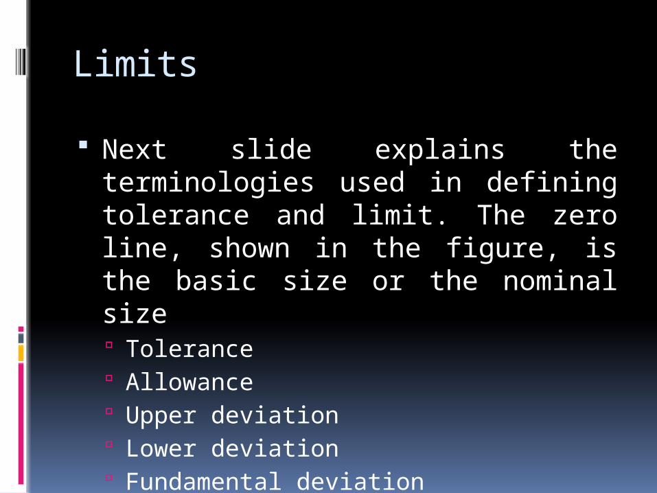
Next slide explains the terminologies used in defining tolerance and limit. The zero line, shown in the figure, is the basic size or the nominal size Tolerance Allowance Upper deviation Lower deviation Fundamental deviation
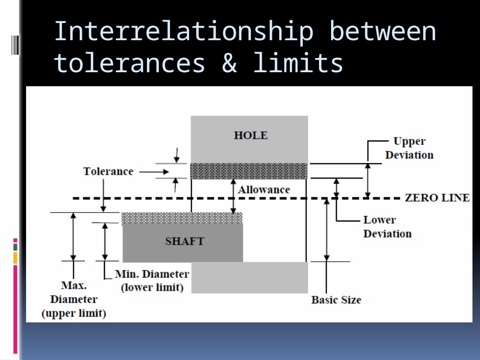
Interrelationship between tolerances & limits
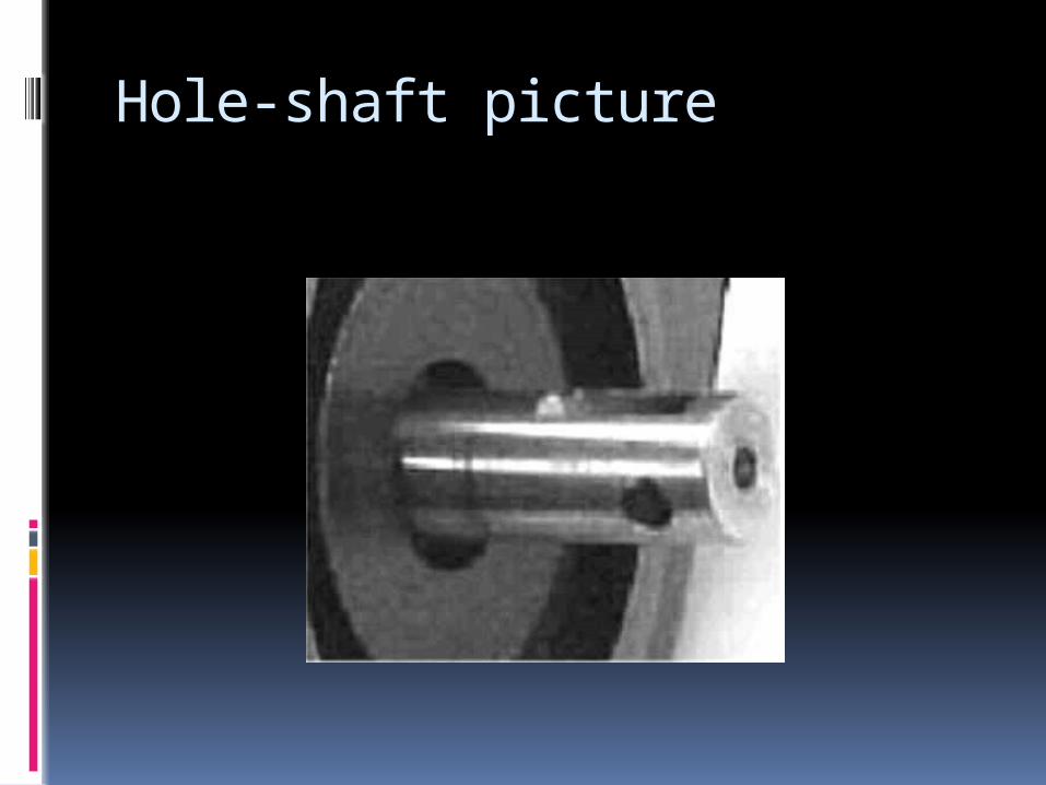
Hole-shaft picture

Basic size
The dimensions obtained by design calculations are called the basic size of components (also called nominal size)
Actual size
The size of a manufactured part found by measurement is called the actual size
Limits
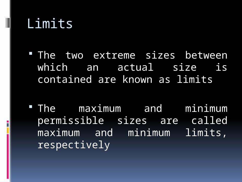
The two extreme sizes between which an actual size is contained are known as limits
The maximum and minimum permissible sizes are called maximum and minimum limits, respectively
Zero line
A straight line to which deviations are referred
Represents the basic size
Zero deviation
Tolerance
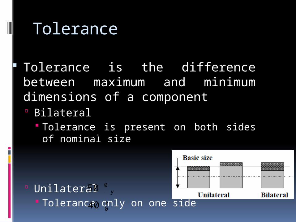
Tolerance is the difference between maximum and minimum dimensions of a component Bilateral
Tolerance is present on both sides of nominal size
Unilateral Tolerance only on one side
y
y
0
0
40
50
xy
50
Allowance
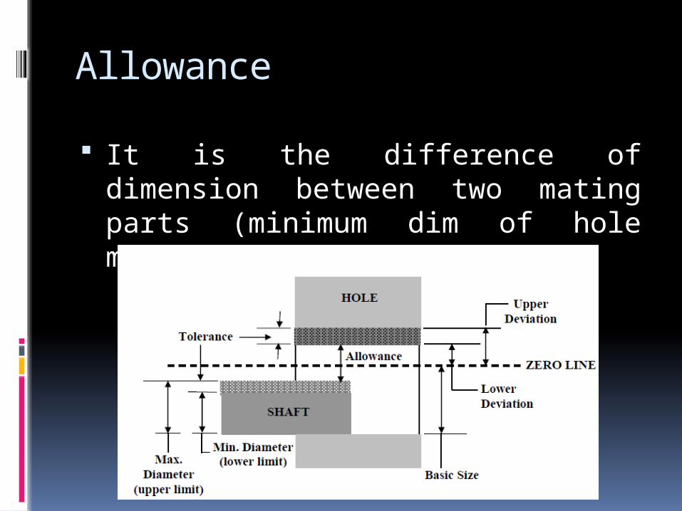
It is the difference of dimension between two mating parts (minimum dim of hole minus maximum dim of shaft)

Upper deviation
It is the difference of dimension between the maximum possible size of the component and its nominal size
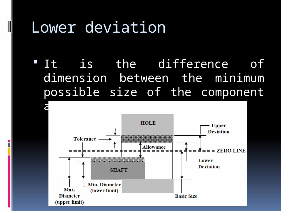
Lower deviation
It is the difference of dimension between the minimum possible size of the component and its nominal size

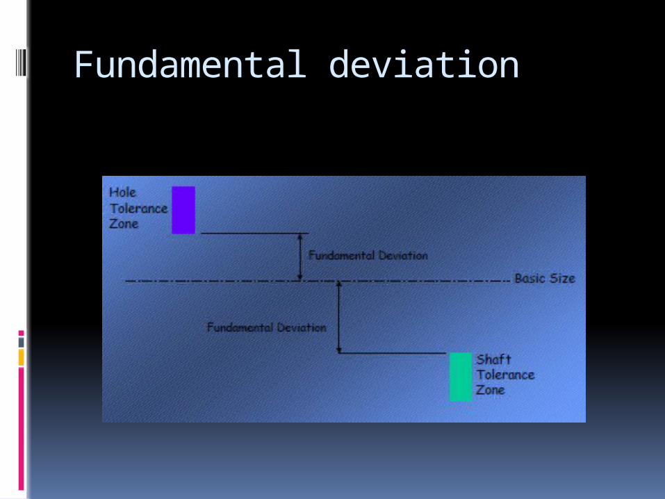
Fundamental deviation It defines the location of the tolerance zone
with respect to the nominal size. For that matter, either of the deviations may be considered
Fit system
The nature of assembly of two mating parts is defined by three types of standard fit system Clearance Fit Transition Fit Interference Fit
Clearance fit
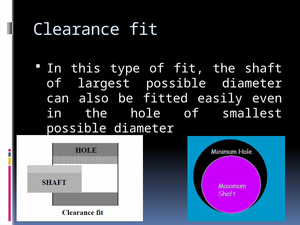
In this type of fit, the shaft of largest possible diameter can also be fitted easily even in the hole of smallest possible diameter
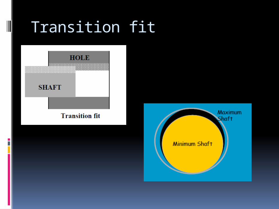
Transition fit
There will be a clearance between the minimum dimension of the shaft and the minimum dimension of the hole
If the shaft dimension is maximum and the hole dimension is minimum then an overlap will result and this creates a certain amount of tightness in the fitting of the shaft inside the hole
Hence, transition fit may have either clearance or overlap in the fit
Transition fit
Interference fit
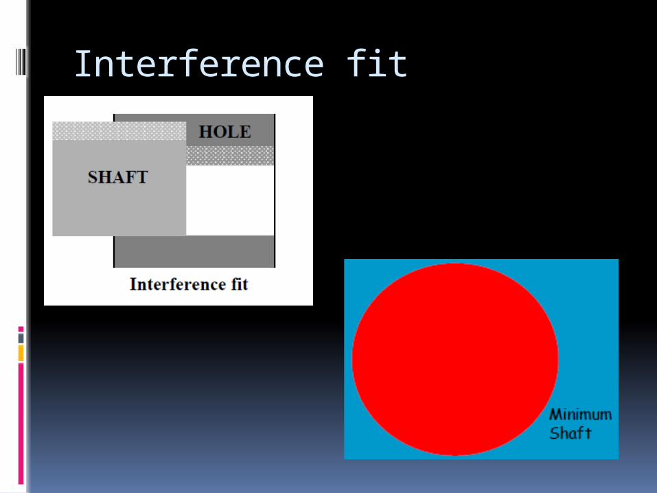
In this case, no matter whatever may be the tolerance level in shaft and the hole, there is always an overlapping of the mating parts
This is known as interference fit
Interference fit is a form of a tight fit
Interference fit
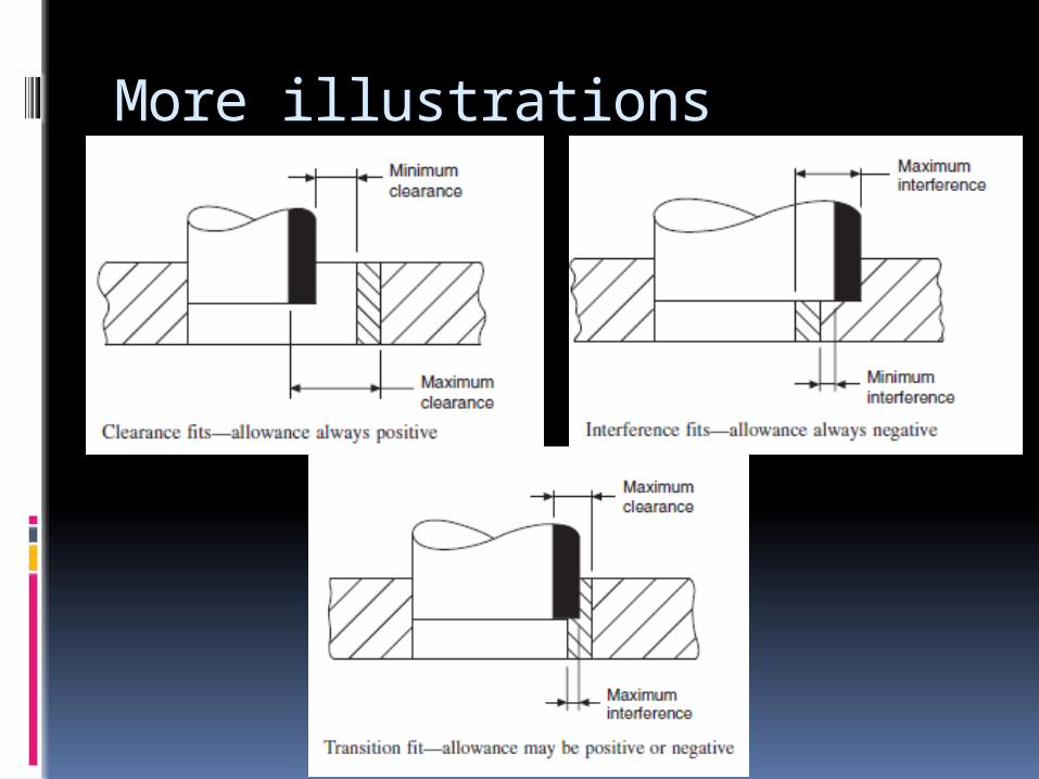
More illustrations
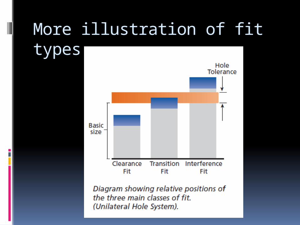
More illustration of fit types
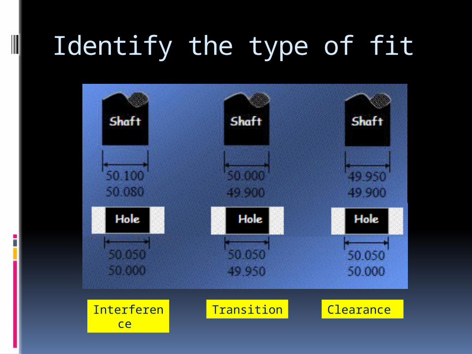
Identify the type of fit
Interference Transition Clearance
Bases of fits
Hole basis Shaft basis
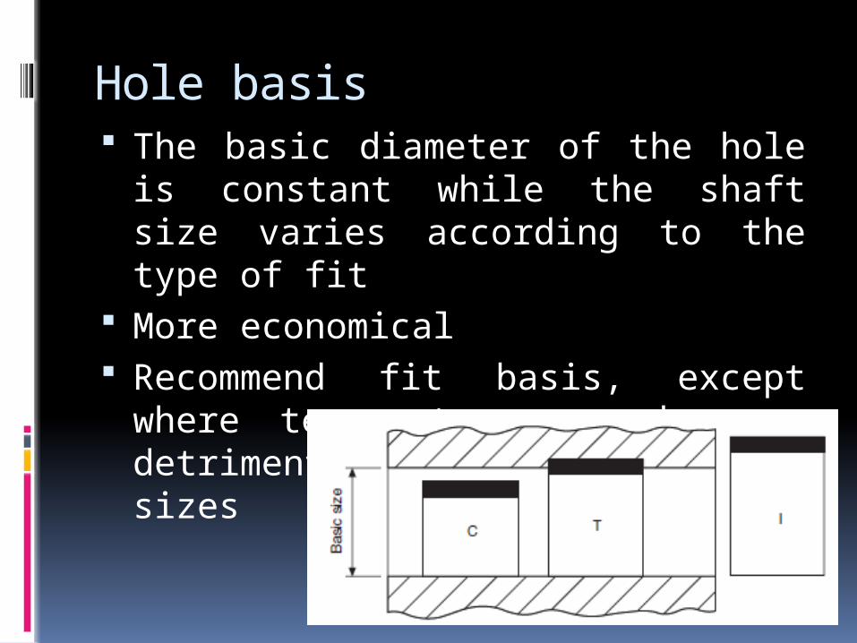
Hole basis The basic diameter of the hole is constant
while the shaft size varies according to the type of fit
More economical Recommend fit basis, except where
temperature may have a detrimental effect on large sizes
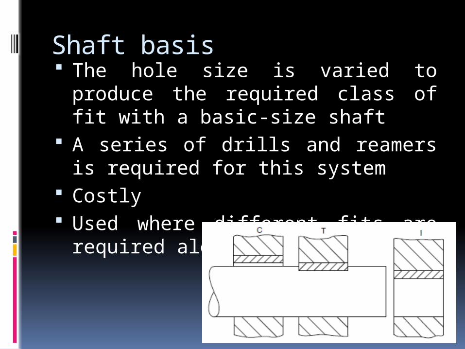
Shaft basis The hole size is varied to produce the required
class of fit with a basic-size shaft A series of drills and reamers is required for
this system Costly Used where different fits are required along a
long shaft
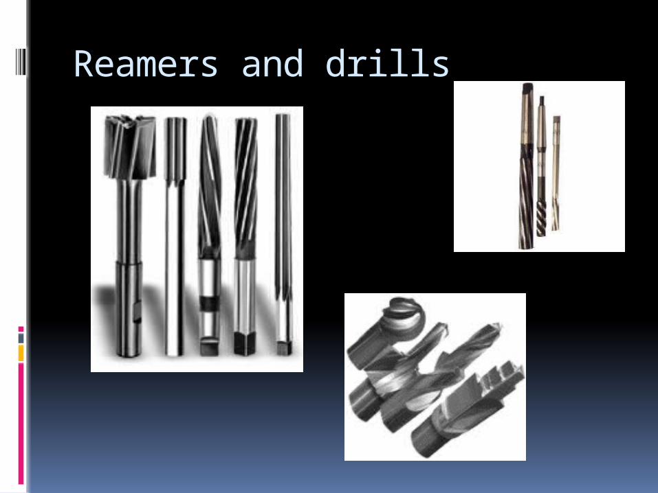
Reamers and drills
Note
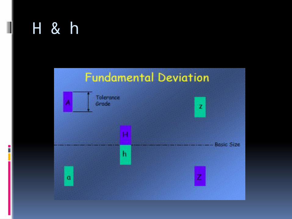
H and h correspond to fundamental deviation of zero
Hole basis; Holes H11 H9 H8 H7 Shafts c11 d10 e9 f7 g6 k6 n6 p6 s6
Holes are always represented by capital letter Shafts are represented by small letter The greater the number the greater or wider
the tolerance
Note
A selection of a pair of these tolerances is huge so standards such as ISO standardise them as will be seen on coming slides
Standards give most useful range of tolerances for various engineering applications
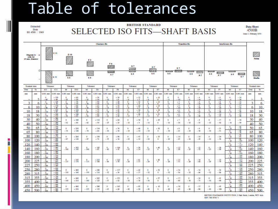
Table of tolerances
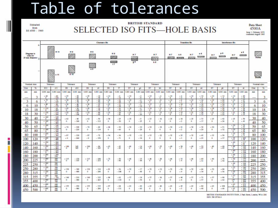
Table of tolerances
Fundamental deviation
H & h
Specification of a fit
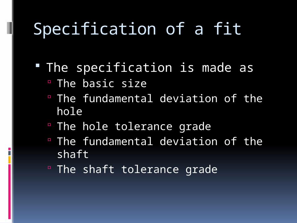
The specification is made as The basic size The fundamental deviation of the hole The hole tolerance grade The fundamental deviation of the shaft The shaft tolerance grade
Note
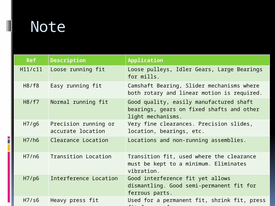
Ref Description Application
H11/c11 Loose running fit Loose pulleys, Idler Gears, Large Bearings for mills.
H8/f8 Easy running fit Camshaft Bearing, Slider mechanisms where both rotary and linear motion is required.
H8/f7 Normal running fit Good quality, easily manufactured shaft bearings, gears on fixed shafts and other light mechanisms.
H7/g6 Precision running or accurate location
Very fine clearances. Precision slides, location, bearings, etc.
H7/h6 Clearance Location Locations and non-running assemblies.
H7/n6 Transition Location Transition fit, used where the clearance must be kept to a minimum. Eliminates vibration.
H7/p6 Interference Location Good interference fit yet allows dismantling. Good semi-permanent fit for ferrous parts.
H7/s6 Heavy press fit Used for a permanent fit, shrink fit, press fit for non-ferrous parts.
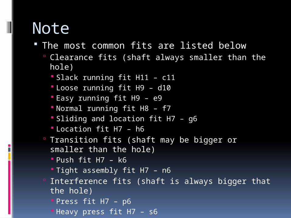
Note The most common fits are listed below
Clearance fits (shaft always smaller than the hole) Slack running fit H11 – c11 Loose running fit H9 – d10 Easy running fit H9 – e9 Normal running fit H8 – f7 Sliding and location fit H7 – g6 Location fit H7 – h6
Transition fits (shaft may be bigger or smaller than the hole) Push fit H7 – k6 Tight assembly fit H7 – n6
Interference fits (shaft is always bigger that the hole) Press fit H7 – p6 Heavy press fit H7 – s6
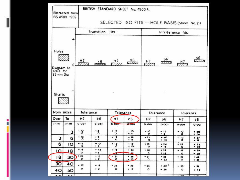
Example 2
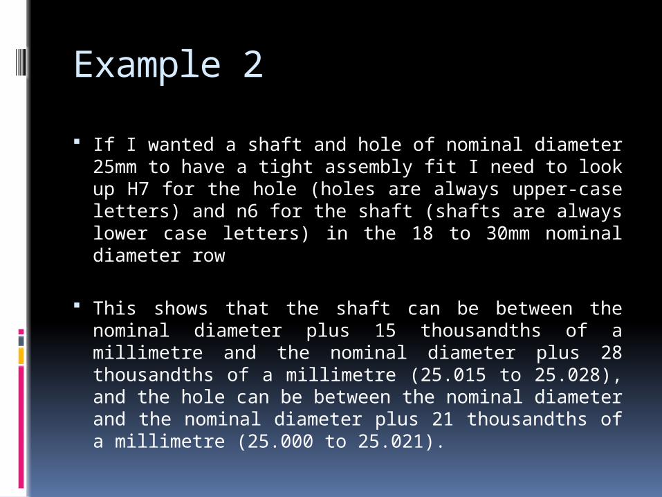
If I wanted a shaft and hole of nominal diameter 25mm to have a tight assembly fit I need to look up H7 for the hole (holes are always upper-case letters) and n6 for the shaft (shafts are always lower case letters) in the 18 to 30mm nominal diameter row
This shows that the shaft can be between the nominal diameter plus 15 thousandths of a millimetre and the nominal diameter plus 28 thousandths of a millimetre (25.015 to 25.028), and the hole can be between the nominal diameter and the nominal diameter plus 21 thousandths of a millimetre (25.000 to 25.021).
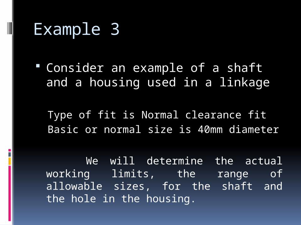
Example 3
Consider an example of a shaft and a housing used in a linkage
Type of fit is Normal clearance fit
Basic or normal size is 40mm diameter
We will determine the actual working limits, the range of allowable sizes, for the shaft and the hole in the housing.
Answer
Nominal diameter size
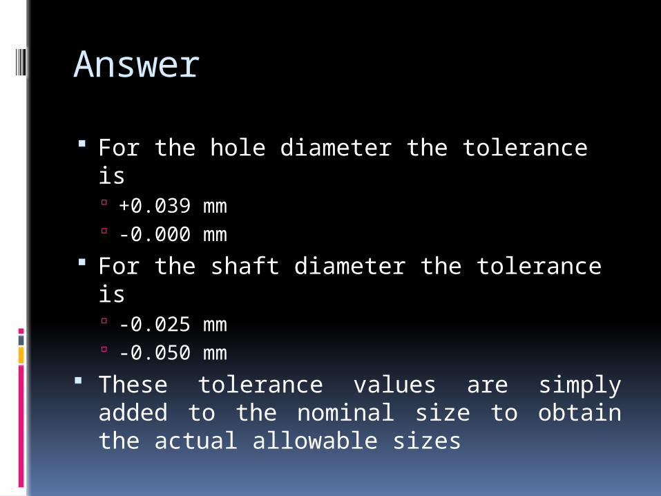
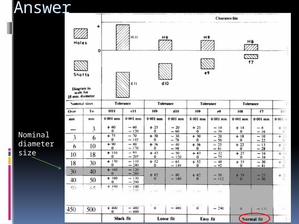
Answer
For the hole diameter the tolerance is +0.039 mm -0.000 mm
For the shaft diameter the tolerance is -0.025 mm -0.050 mm
These tolerance values are simply added to the nominal size to obtain the actual allowable sizes
Answer
Note that this is a clearance fit. As long as the hole and shaft are manufactured within the specified tolerances the hole will always be either slightly oversize or spot on the nominal size and the shaft will always be slightly undersize. This ensures that there will always be a free clearance fit
Answer
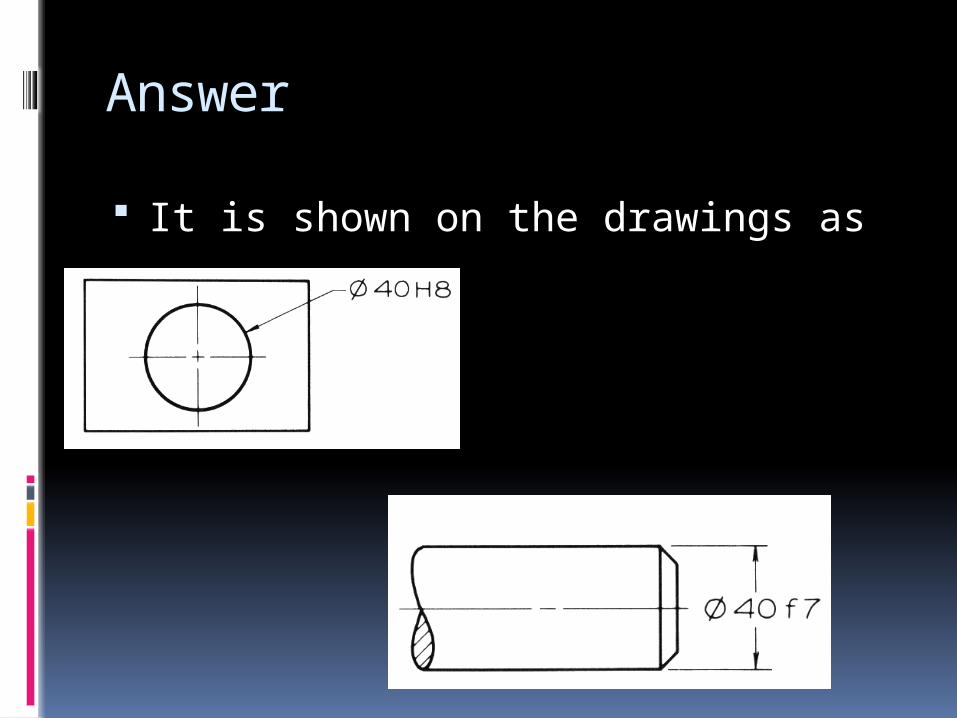
It is shown on the drawings as
Answer
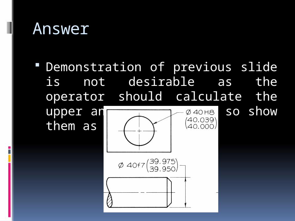
Demonstration of previous slide is not desirable as the operator should calculate the upper and lower limits, so show them as
Answer
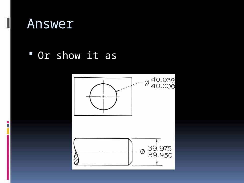
Or show it as