Embed Size (px)
Citation preview
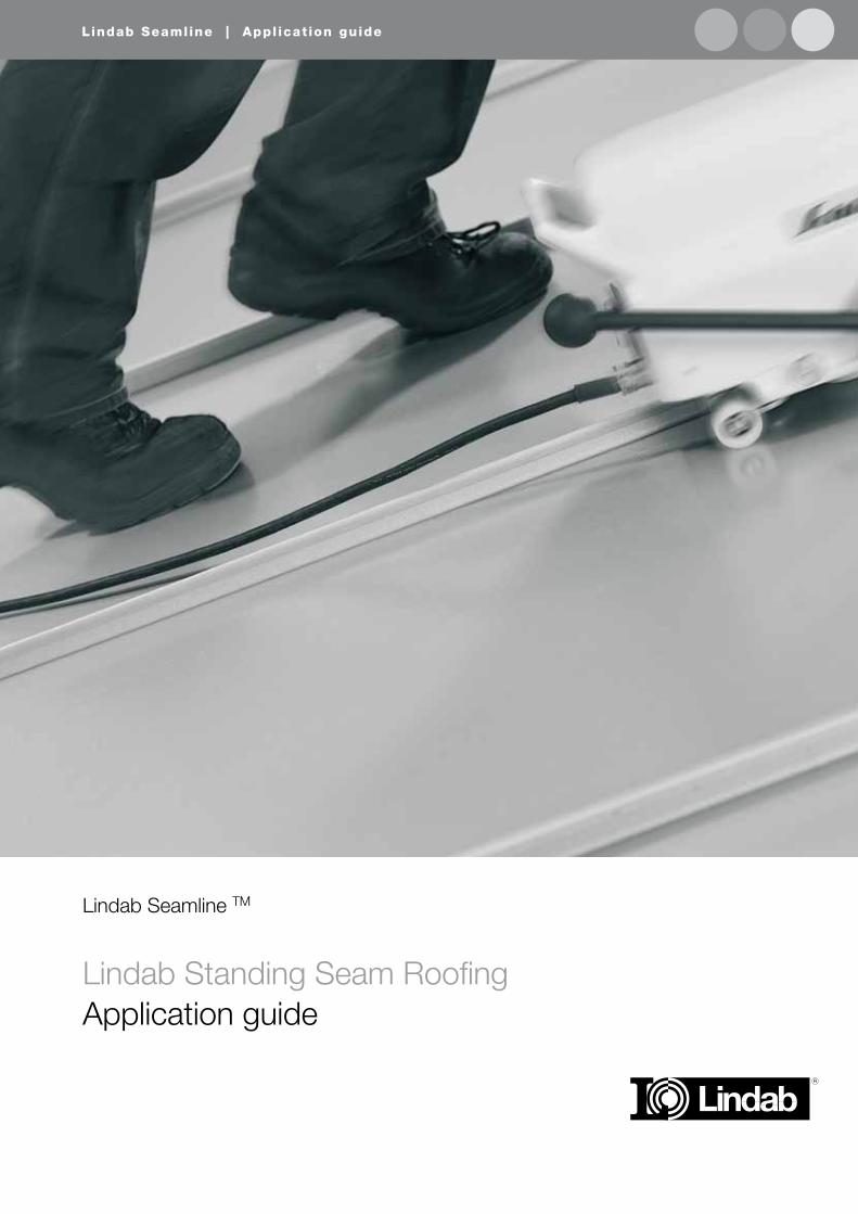
Lindab Seamline | Appl icat ion guide
Lindab Standing Seam RoofingApplication guide
Lindab Seamline TM
Lindab Seamline | Standing Seam Roof ing
2
CONTENTS
3 Detail references4 Sheet steel as roofing material5 Choice between long strip roofing and sheet roofing6 Material for sheet steel roofing7 Thermal movements8 Strip lengths and fixed zones9 Roof covering for sheet steel roofing9 Securing by means of clips10 Wind loading11 Securing the clips to timber roof covering12 Roofing on timber roof covering – design details13 Seam Cross section 14 Detail at eaves – external gutter 15 Detail at eaves with eaves gutter for pitch minimum 30°16 Detail at eaves with eaves gutter for pitch 14-30°17 Detail at ridge17 Detail at gable barge board18 Ventilating ridge 19 Coping 20 Flat sheet roofing with aluminium-zinc 21 Valley21 Sunken valley 22 Connection to an upstanding part of the building 23 Sunken valley 24 Flashing at roof upstand 26 Work procedure for folding
This handbook deals with long strip roofing with HB Polyester and aluminium-
zinc on a boarded roof covering.
The instructions in this handbook are basically of a general nature. However,
the detailed drawings are only intended to show typical designs, and they
should be modified from case to case to suit the actual conditions.
3
Lindab Seamline | Standing Seam Roof ing
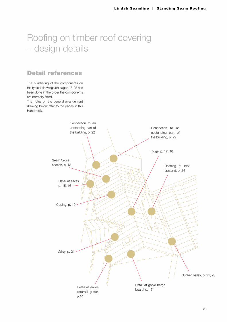
Roofing on timber roof covering – design details
Detail references
The numbering of the components on the typical drawings on pages 13-25 has been done in the order the components are normally fitted.The notes on the general arrangement drawing below refer to the pages in this Handbook.
Detail at eaves external gutter, p.14
Detail at gable barge board, p. 17
Valley, p. 21
Coping, p. 19
Connection to an upstanding part of the building, p. 22
Ridge, p. 17, 18
Sunken valley, p. 21, 23
Connection to an upstanding part of the building, p. 22
Seam Cross section, p. 13
Detail at eaves p. 15, 16
Flashing at roof upstand, p. 24
4
Lindab Seamline | Standing Seam Roof ing
Technical facts
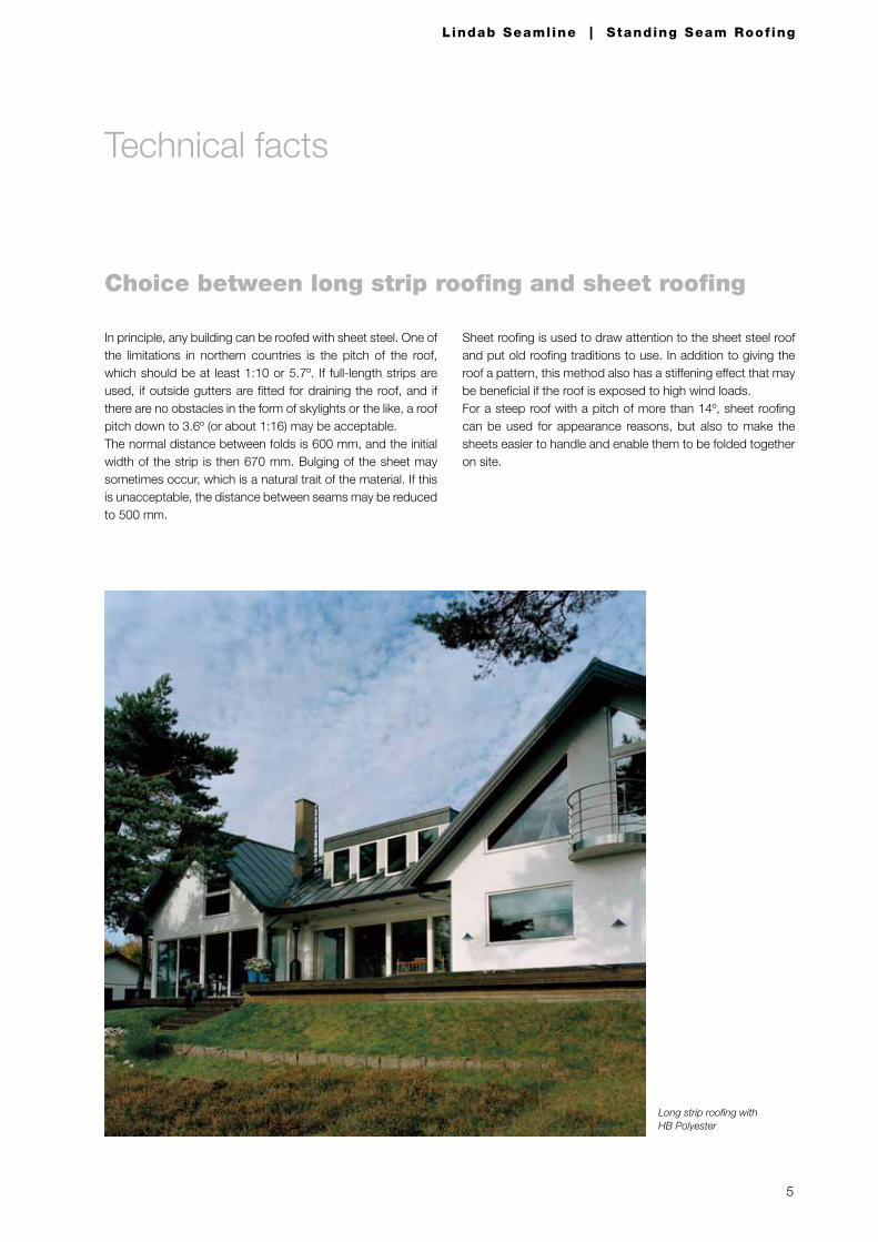
Sheet steel has long traditions as roofing material. However, sheet steel has undergone great changes over the years. The use of galvanized sheet steel that was then painted on site be-gan towards the end of the 19th century.To an increasing extent, prepainted or aluminium-zinc coated sheet steel of a special mild grade are being used today.During the 19th century, the sheet roofing method was used for sheet steel roofing. Short sheets are used in this method, and standing seams and transverse seams are then made to join the sheets together. Sheet roofing is used today mainly for building on which the aim is to accentuate the appearance and quality, and also to put to use bygone roofing traditions.However, long strip roofing dominates today as the sheet steel roofing method. Long strip roofing can be used for all types of buildings, provided that the pitch is sufficient, i.e. about 6º.Many factors favour the use of sheet steel as roofing material. The reasons for using sheet steel as roofing material on indus-trial, commercial and residential buildings include appearance, resistance to fire, resistance to physical damage and a long useful life. In addition, prepainted as well as aluminium-zinc coated sheet steel is 100% recyclable, which makes sheet steel a highly environmentally appropriate product.Long strip roofing is often particularly appropriate if the roof pitch is shallow.
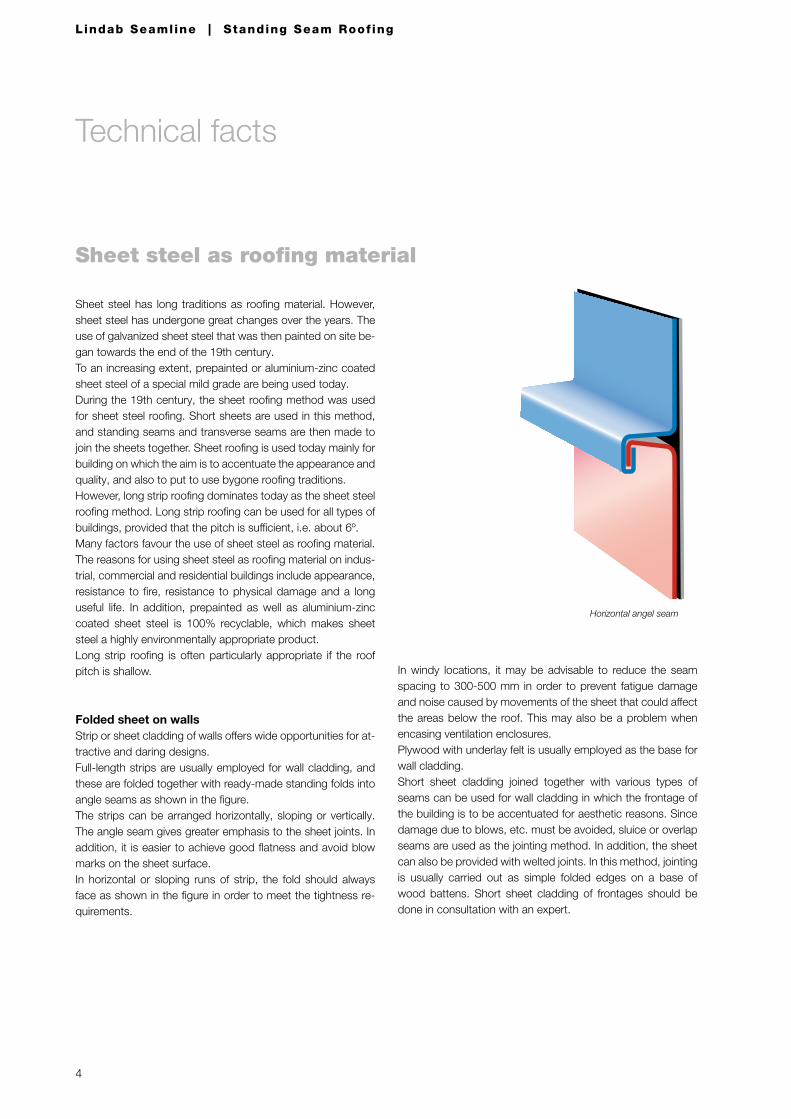
Folded sheet on wallsStrip or sheet cladding of walls offers wide opportunities for at-tractive and daring designs.Full-length strips are usually employed for wall cladding, and these are folded together with ready-made standing folds into angle seams as shown in the figure.The strips can be arranged horizontally, sloping or vertically. The angle seam gives greater emphasis to the sheet joints. In addition, it is easier to achieve good flatness and avoid blow marks on the sheet surface.In horizontal or sloping runs of strip, the fold should always face as shown in the figure in order to meet the tightness re-quirements.
Sheet steel as roofing material
In windy locations, it may be advisable to reduce the seam spacing to 300-500 mm in order to prevent fatigue damage and noise caused by movements of the sheet that could affect the areas below the roof. This may also be a problem when encasing ventilation enclosures.Plywood with underlay felt is usually employed as the base for wall cladding.Short sheet cladding joined together with various types of seams can be used for wall cladding in which the frontage of the building is to be accentuated for aesthetic reasons. Since damage due to blows, etc. must be avoided, sluice or overlap seams are used as the jointing method. In addition, the sheet can also be provided with welted joints. In this method, jointing is usually carried out as simple folded edges on a base of wood battens. Short sheet cladding of frontages should be done in consultation with an expert.
Horizontal angel seam
Choice between long strip roofing and sheet roofing
In principle, any building can be roofed with sheet steel. One of the limitations in northern countries is the pitch of the roof, which should be at least 1:10 or 5.7º. If full-length strips are used, if outside gutters are fitted for draining the roof, and if there are no obstacles in the form of skylights or the like, a roof pitch down to 3.6º (or about 1:16) may be acceptable.The normal distance between folds is 600 mm, and the initial width of the strip is then 670 mm. Bulging of the sheet may sometimes occur, which is a natural trait of the material. If this is unacceptable, the distance between seams may be reduced to 500 mm.
Sheet roofing is used to draw attention to the sheet steel roof and put old roofing traditions to use. In addition to giving the roof a pattern, this method also has a stiffening effect that may be beneficial if the roof is exposed to high wind loads.For a steep roof with a pitch of more than 14º, sheet roofing can be used for appearance reasons, but also to make the sheets easier to handle and enable them to be folded together on site.
Long strip roofing with HB Polyester
Technical facts
5
Lindab Seamline | Standing Seam Roof ing
6
Lindab Seamline | Standing Seam Roof ing
Material for sheet steel roofing
Our Seamline products have a special steel grade suitable for both mechanical and manual folding.The steel is so mild that the spring-back is practically zero, and this is vitally important for ensuring that the seams will seal reli-ably. The yield strength of the material is around 180 N/mm2. The thickness of the steel is as standard 0,6 mm.
HB PolyesterHB Polyester is a prepainted product adapted for sheet steel roofing (HB=High Build).The metallic coating Z 350 hot-dip galvanized is used for the prepainted HB Polyester grade, i.e. a zinc coating of 350 g/m2 on both sides. The thickness of metal coating is about 25 µm (0.025 mm) on each side.
HB Polyester with dual finishesThe HB Polyester is produced with dual types of surface fin-ishes, the normal type (HB Polyester) and a matt type (Matt HB Polyester). Aesthetical requirements indicate what is best suit-ed for a specific building.HB Polyester and Matt HB Polyester have a coating, with a to-tal thickness of 50 µm. The thickness of the paint coat is opti-mized for wear resistance, weathering resistance and con-sumption of resources. The coating has very good gloss- and colour retention proper-ties. The specification of the coating is given in a separate product leaflet.
A thin coat of epoxy type paint is applied to the underside of the sheet. The colour of this paint is blue. HB Polyester be-longs to corrosion protection category RC4 as per ENV 10169-2.
Aluminium-zincAluminium-zinc is a aluminium-zinc coated steel sheet that can be used unpainted up to corrosivity category C4 as per EN ISO 12944-2, where C1 means very low and C5 means very high corrosivity.The alloy of the metal coat has a weight percentage of 55% aluminium, 43.4% zinc and approx. 1.6 % silica with a coat weight of 185 g/m2 per double side. The surface has been treated with SPT (Surface Protection Treatment) to prevent stains during handling and to ease shaping. The tinsmith qual-ity is an extra soft steel sheet. The steel has practically spring back so that tight seams can be made. The material may be seamed by machine and by hand.
AppearanceThe surface is initially glossy metal with a rose pattern but after some time it turns greyish, and eventually it becomes matt grey.
For more technical information about the materials HB Polyes-ter and aluminium-zinc, see separate documentation.
Technical facts
7
Lindab Seamline | Standing Seam Roof ing
Thermal movements
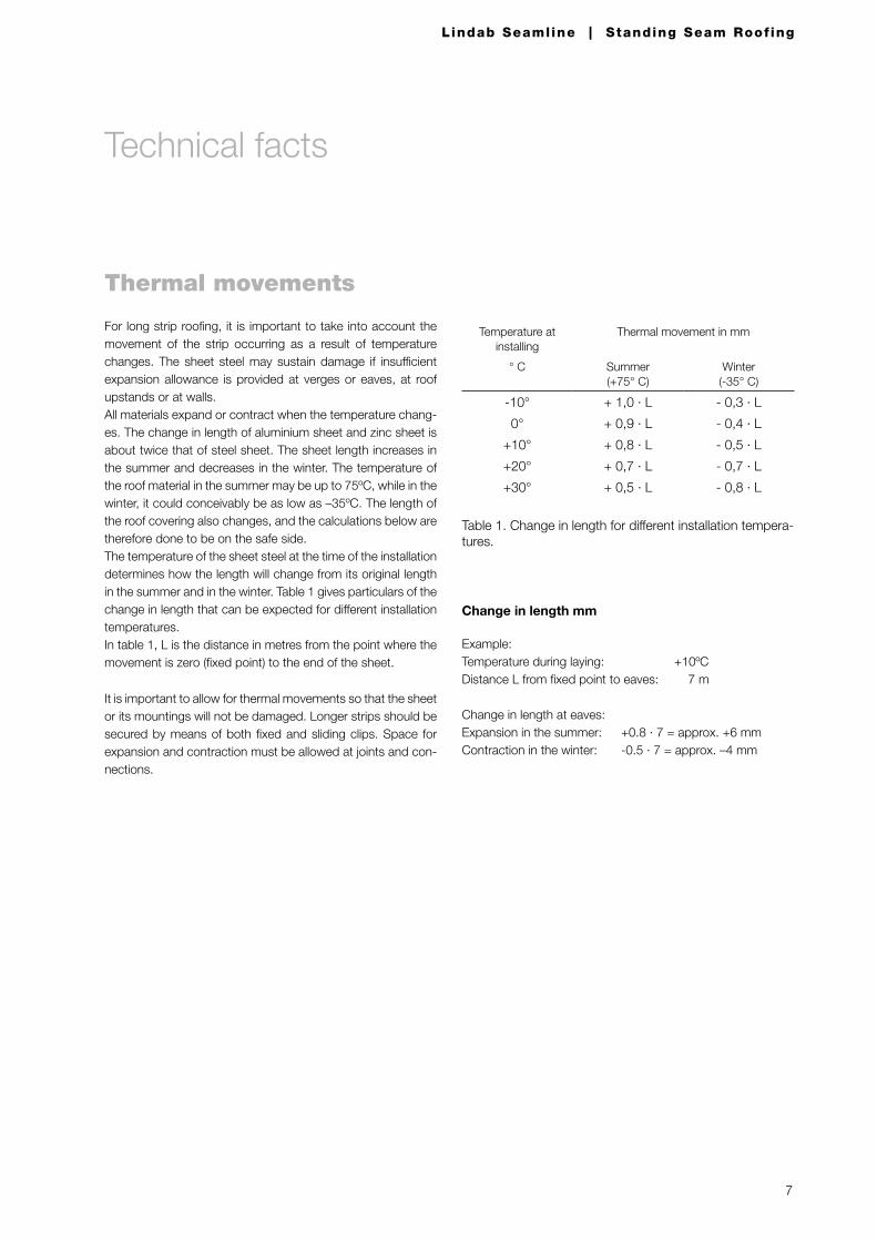
For long strip roofing, it is important to take into account the movement of the strip occurring as a result of temperature changes. The sheet steel may sustain damage if insufficient expansion allowance is provided at verges or eaves, at roof upstands or at walls.All materials expand or contract when the temperature chang-es. The change in length of aluminium sheet and zinc sheet is about twice that of steel sheet. The sheet length increases in the summer and decreases in the winter. The temperature of the roof material in the summer may be up to 75ºC, while in the winter, it could conceivably be as low as –35ºC. The length of the roof covering also changes, and the calculations below are therefore done to be on the safe side.The temperature of the sheet steel at the time of the installation determines how the length will change from its original length in the summer and in the winter. Table 1 gives particulars of the change in length that can be expected for different installation temperatures.In table 1, L is the distance in metres from the point where the movement is zero (fixed point) to the end of the sheet.
Table 1. Change in length for different installation tempera-tures.
Example:Temperature during laying: +10ºCDistance L from fixed point to eaves: 7 m
Change in length at eaves:Expansion in the summer: +0.8 · 7 = approx. +6 mmContraction in the winter: -0.5 · 7 = approx. –4 mm
It is important to allow for thermal movements so that the sheet or its mountings will not be damaged. Longer strips should be secured by means of both fixed and sliding clips. Space for expansion and contraction must be allowed at joints and con-nections.
Change in length mm
Temperature at installing
Thermal movement in mm
° C Summer(+75° C)
Winter(-35° C)
-10° + 1,0 · L - 0,3 · L
0° + 0,9 · L - 0,4 · L
+10° + 0,8 · L - 0,5 · L
+20° + 0,7 · L - 0,7 · L
+30° + 0,5 · L - 0,8 · L
Technical facts
8
Lindab Seamline | Standing Seam Roof ing
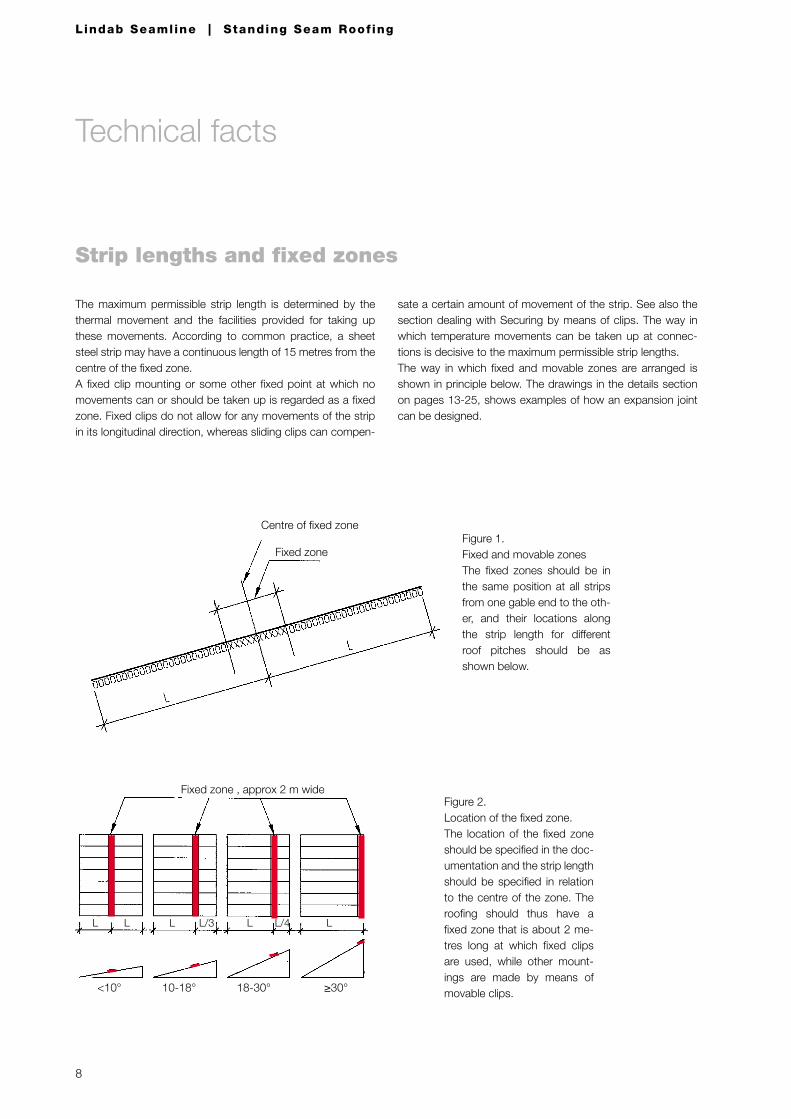
Strip lengths and fixed zones
The maximum permissible strip length is determined by the thermal movement and the facilities provided for taking up these movements. According to common practice, a sheet steel strip may have a continuous length of 15 metres from the centre of the fixed zone.A fixed clip mounting or some other fixed point at which no movements can or should be taken up is regarded as a fixed zone. Fixed clips do not allow for any movements of the strip in its longitudinal direction, whereas sliding clips can compen-
<10° 10-18° 18-30° ≥30°
Fixed zone , approx 2 m wideFigure 2. Location of the fixed zone.The location of the fixed zone should be specified in the doc-umentation and the strip length should be specified in relation to the centre of the zone. The roofing should thus have a fixed zone that is about 2 me-tres long at which fixed clips are used, while other mount-ings are made by means of movable clips.
Centre of fixed zone
Fixed zoneFigure 1. Fixed and movable zonesThe fixed zones should be in the same position at all strips from one gable end to the oth-er, and their locations along the strip length for different roof pitches should be as shown below.
sate a certain amount of movement of the strip. See also the section dealing with Securing by means of clips. The way in which temperature movements can be taken up at connec-tions is decisive to the maximum permissible strip lengths.The way in which fixed and movable zones are arranged is shown in principle below. The drawings in the details section on pages 13-25, shows examples of how an expansion joint can be designed.
L L L L LL/3 L/4
Technical facts
9
Lindab Seamline | Standing Seam Roof ing
Roof covering for sheet steel roofing
Securing by means of clips
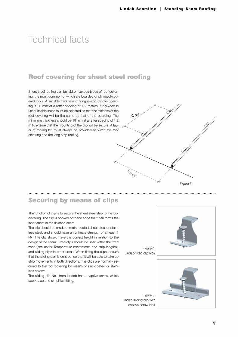
The function of clip is to secure the sheet steel strip to the roof covering. The clip is hooked onto the edge that then forms the inner sheet in the finished seam.The clip should be made of metal-coated sheet steel or stain-less steel, and should have an ultimate strength of at least 1 kN. The clip should have the correct height in relation to the design of the seam. Fixed clips should be used within the fixed zone (see under Temperature movements and strip lengths), and sliding clips in other areas. When fitting the clips, ensure that the sliding part is centred, so that it will be able to take up strip movements in both directions. The clips are normally se-cured to the roof covering by means of zinc-coated or stain-less screws.The sliding clip No1 from Lindab has a captive screw, which speeds up and simplifies fitting.
Figure 5. Lindab sliding clip with
captive screw No1
Figure 4.Lindab fixed clip No2
Figure 3.
Technical facts
Sheet steel roofing can be laid on various types of roof cover-ing, the most common of which are boarded or plywood-cov-ered roofs. A suitable thickness of tongue-and-groove board-ing is 23 mm at a rafter spacing of 1.2 metres. If plywood is used, its thickness must be selected so that the stiffness of the roof covering will be the same as that of the boarding. The minimum thickness should be 19 mm at a rafter spacing of 1.2 m to ensure that the mounting of the clip will be secure. A lay-er of roofing felt must always be provided between the roof covering and the long strip roofing.
10
Lindab Seamline | Standing Seam Roof ing
Wind loading
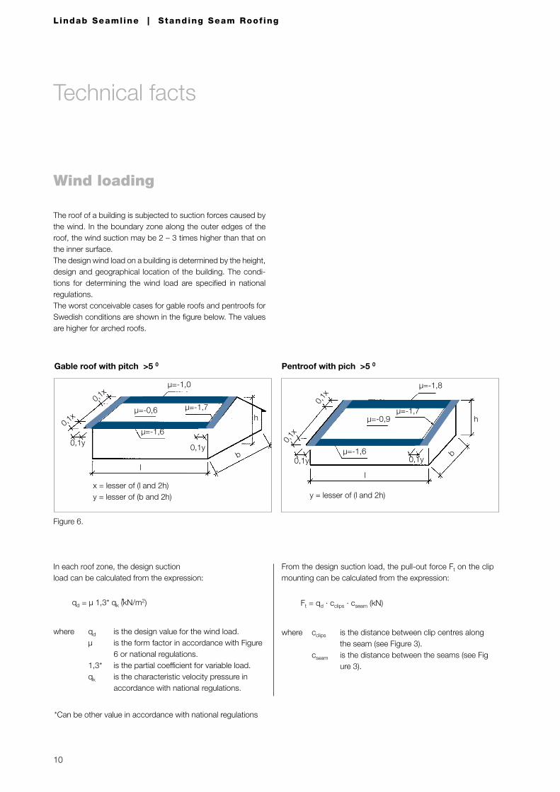
The roof of a building is subjected to suction forces caused by the wind. In the boundary zone along the outer edges of the roof, the wind suction may be 2 – 3 times higher than that on the inner surface.The design wind load on a building is determined by the height, design and geographical location of the building. The condi-tions for determining the wind load are specified in national regulations.The worst conceivable cases for gable roofs and pentroofs for Swedish conditions are shown in the figure below. The values are higher for arched roofs.
Gable roof with pitch >5 0
x = lesser of (l and 2h)y = lesser of (b and 2h)
Pentroof with pich >5 0
y = lesser of (l and 2h)
From the design suction load, the pull-out force Ft on the clip mounting can be calculated from the expression:
where cclips is the distance between clip centres along the seam (see Figure 3). cseam is the distance between the seams (see Fig ure 3).
Ft = qd · cclips · cseam (kN)
In each roof zone, the design suction load can be calculated from the expression:
where qd is the design value for the wind load. µ is the form factor in accordance with Figure 6 or national regulations. 1,3* is the partial coefficient for variable load. qk is the characteristic velocity pressure in accordance with national regulations.
Figure 6.
qd = µ 1,3* qk (kN/m2)
*Can be other value in accordance with national regulations
*
µ=-1,6
µ=-0,6 µ=-1,7
µ=-1,0
h
b
0,1y
0,1x
0,1x
l
0,1y
µ=-1,8
µ=-0,9
µ=-1,6 b
l
h
0,1y
0,1x
0,1x
0,1y
µ=-1,7
Technical facts
11
Lindab Seamline | Standing Seam Roof ing
Securing the clips to timber roof covering
Clips should be secured by means of screws. Only one screw is normally needed for every clip. The conditions for calculating the pull-out forces in a timber roof covering are specified in na-tional regulations. The pull-out values obtained from experi-ence for 4.0 mm screws in a timber roof covering are given in Table 2 below.
Table 2.Design pull-out forces for screws.- Timber boarding or plywood- One 4.0 mm diameter screw- Design value Rd
Design conditionsThe pull-out force Ft must be lower than or equal to the design pull-out force Rd for the clip mounting (Ft < Rd)
Clip spacingClips secured with screws can normally be spaced 600 mm apart, although a check calculation must be made for clips in boundary zones in locations exposed to wind forces. Particu-lars of the clip spacing on the various surfaces of the roof must be included in the drawing documentation.It is always economically and technically justifiable to adjust the clip spacing to suit the wind loads, the fasteners and the roof covering material.For the conditions specified above, Table 3 shows suitable spacing of clips, each of which of secured by one screw.
Table 3. Spacing of clips for gable roofs and pentroofs.- Roof covering of 23 mm timber boarding- One screw per clip- Form factors for wind as per national regulations. The values in the table below are based on Swedish regulations- Seam spacing of 600 mm- Other conditions in accordance with Table 2.
1) Applies to the roof corners only for a roof pitch of <5º on a distance of 0.25x times 0.25y (0.25x for pentroof) in the cor-ners as shown in Figure 6.
Timber thickness mm Rd kN
16 0,55
19 0,69
23 0,87
25 0,96
Gable roof and pent roofClip spacing in mm.
Wind loadqkkN/m2
Inner surface Boundary zone
Corners1) µ = -2,6
0,4 600 600 600
0,5 600 600 600
0,6 600 600 600
0,7 600 600 600
0,8 600 600 530
0,9 600 600 470
1,0 600 600 430
1,1 600 560 390
1,2 600 510 360
Technical facts
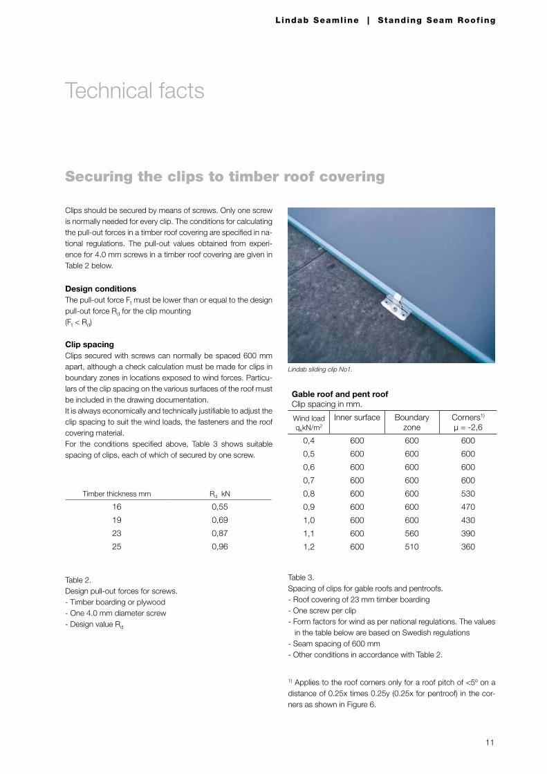
Lindab sliding clip No1.
12
Lindab Seamline | Standing Seam Roof ing
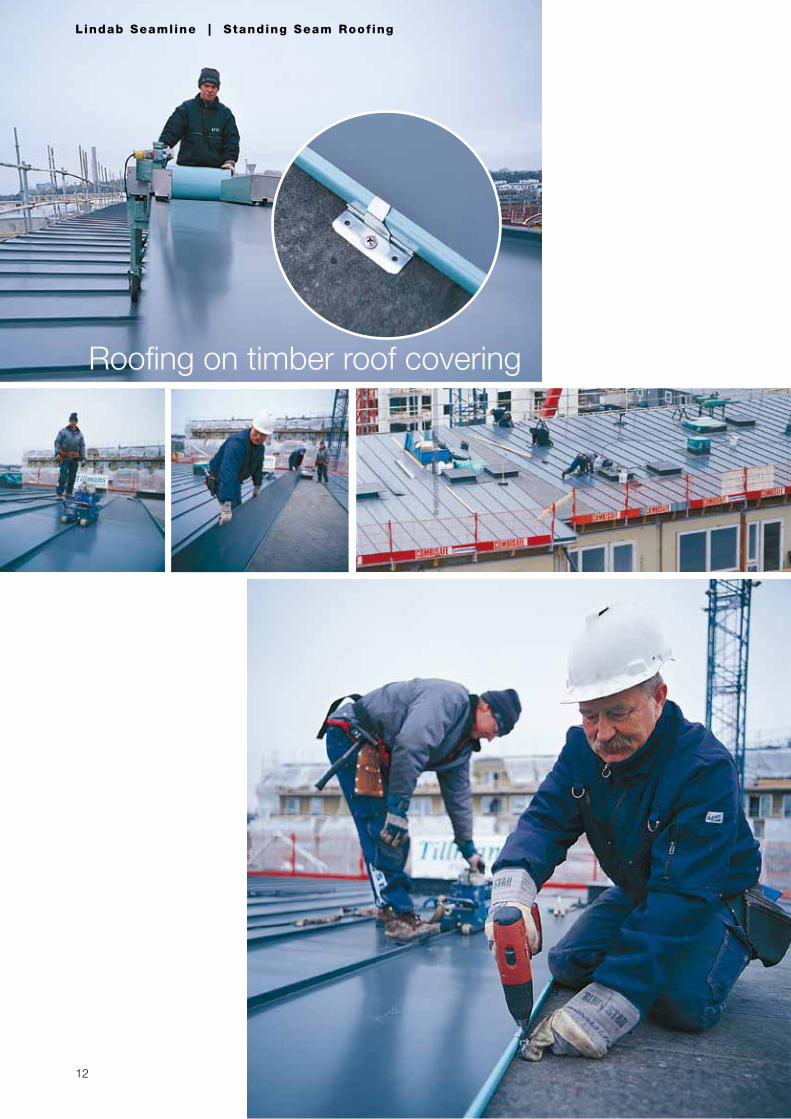
Roofing on timber roof covering
13
Lindab Seamline | Standing Seam Roof ing
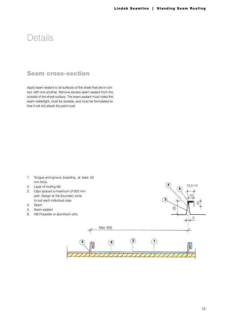
Seam cross-section
Apply seam sealant to all surfaces of the sheet that are in con-tact with one another. Remove excess seam sealant from the outside of the sheet surface. The seam sealant must make the seam watertight, must be durable, and must be formulated so that it will not attack the paint coat.
1263
Max. 600
45
10
12,5-14
5
10
25
3
Details
1. Tongue-and-groove boarding, at least 23 mm thick
2. Layer of roofing felt3. Clips spaced a maximum of 600 mm
part. Design at the boundary zone to suit each individual case
4. Seam5. Seam sealant6. HB Polyester or aluminium-zinc
14
Lindab Seamline | Standing Seam Roof ing
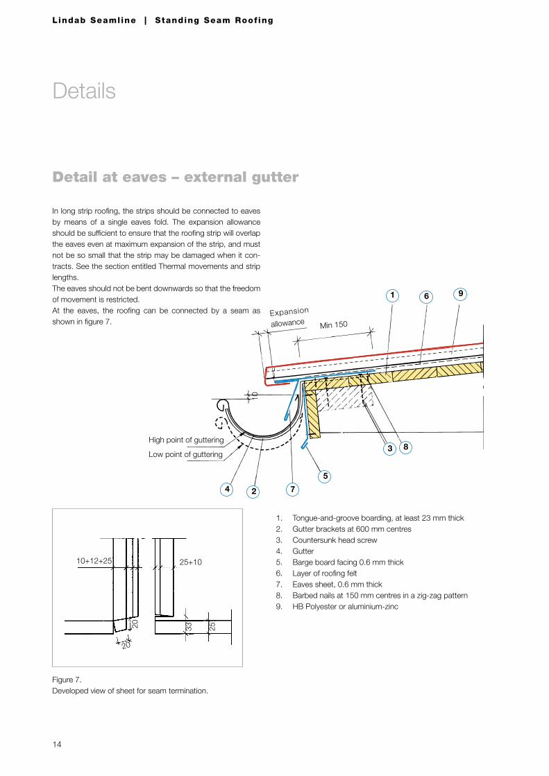
Detail at eaves – external gutter
1. Tongue-and-groove boarding, at least 23 mm thick2. Gutter brackets at 600 mm centres3. Countersunk head screw4. Gutter5. Barge board facing 0.6 mm thick6. Layer of roofing felt7. Eaves sheet, 0.6 mm thick8. Barbed nails at 150 mm centres in a zig-zag pattern9. HB Polyester or aluminium-zinc
25+1010+12+25
253320
20
Figure 7. Developed view of sheet for seam termination.
3 8High point of guttering
Low point of guttering
10
Min 150Expansion
allowance
961
2 74
5
Details
In long strip roofing, the strips should be connected to eaves by means of a single eaves fold. The expansion allowance should be sufficient to ensure that the roofing strip will overlap the eaves even at maximum expansion of the strip, and must not be so small that the strip may be damaged when it con-tracts. See the section entitled Thermal movements and strip lengths.The eaves should not be bent downwards so that the freedom of movement is restricted.At the eaves, the roofing can be connected by a seam as shown in figure 7.
15
Lindab Seamline | Standing Seam Roof ing
10
6
9
7
5
3
4
2
1
8
11
12
Expansion
allowan
ce
High point of guttering
Slope 1:75Low point of guttering
Min=100
Min. 450
150
10
9
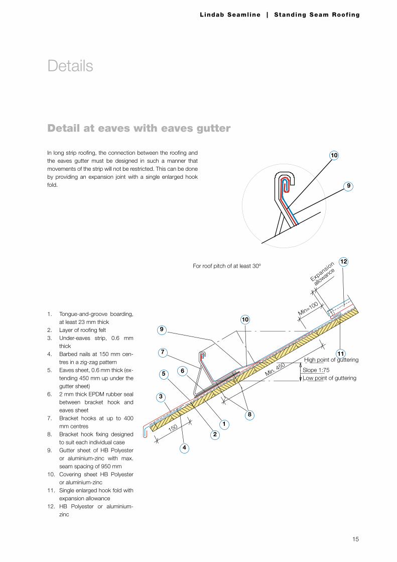
Detail at eaves with eaves gutter
1. Tongue-and-groove boarding, at least 23 mm thick
2. Layer of roofing felt3. Under-eaves strip, 0.6 mm
thick4. Barbed nails at 150 mm cen-
tres in a zig-zag pattern5. Eaves sheet, 0.6 mm thick (ex-
tending 450 mm up under the gutter sheet)
6. 2 mm thick EPDM rubber seal between bracket hook and eaves sheet
7. Bracket hooks at up to 400 mm centres
8. Bracket hook fixing designed to suit each individual case
9. Gutter sheet of HB Polyester or aluminium-zinc with max. seam spacing of 950 mm
10. Covering sheet HB Polyester or aluminium-zinc
11. Single enlarged hook fold with expansion allowance
12. HB Polyester or aluminium-zinc
In long strip roofing, the connection between the roofing and the eaves gutter must be designed in such a manner that movements of the strip will not be restricted. This can be done by providing an expansion joint with a single enlarged hook fold.
For roof pitch of at least 30º
Details
16
Lindab Seamline | Standing Seam Roof ing
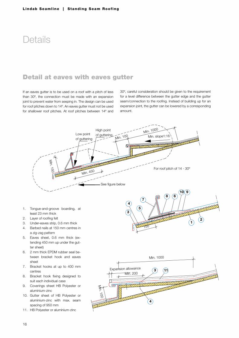
If an eaves gutter is to be used on a roof with a pitch of less than 30º, the connection must be made with an expansion joint to prevent water from seeping in. The design can be used for roof pitches down to 14º. An eaves gutter must not be used for shallower roof pitches. At roof pitches between 14º and
For roof pitch of 14 - 30º
See figure below
Min. 450
Min. 150
Min. 100 Min. 1000
Low point of guttering
High point of guttering Min. slope1:16
1. Tongue-and-groove boarding, at least 23 mm thick
2. Layer of roofing felt3. Under-eaves strip, 0.6 mm thick4. Barbed nails at 150 mm centres in
a zig-zag pattern5. Eaves sheet, 0.6 mm thick (ex-
tending 450 mm up under the gut-ter sheet)
6. 2 mm thick EPDM rubber seal be-tween bracket hook and eaves sheet
7. Bracket hooks at up to 400 mm centres
8. Bracket hook fixing designed to suit each individual case
9. Coverings sheet HB Polyester or aluminium-zinc
10. Gutter sheet of HB Polyester or aluminium-zinc with max. seam spacing of 950 mm
11. HB Polyester or aluminium-zinc
Min. 100
Expansion allowance 3 11
4
Min. 1000
Min. 200
7
9
12
68
45
150
3
10
Detail at eaves with eaves gutter
Details
30º, careful consideration should be given to the requirement for a level difference between the gutter edge and the gutter seam/connection to the roofing. Instead of building up for an expansion joint, the gutter can be lowered by a corresponding amount.
17
Lindab Seamline | Standing Seam Roof ing
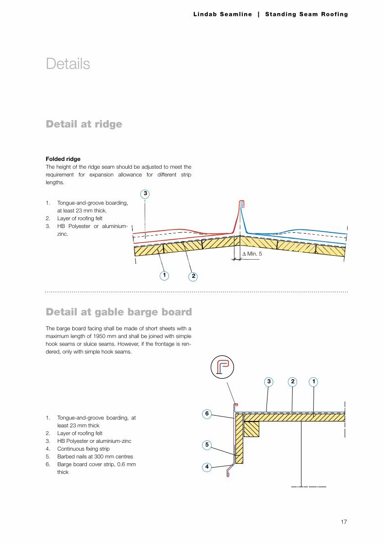
Detail at ridge
1. Tongue-and-groove boarding, at least 23 mm thick.
2. Layer of roofing felt3. HB Polyester or aluminium-
zinc.
Folded ridgeThe height of the ridge seam should be adjusted to meet the requirement for expansion allowance for different strip lengths.
1 2
3
∆ Min. 5
1. Tongue-and-groove boarding, at least 23 mm thick
2. Layer of roofing felt3. HB Polyester or aluminium-zinc4. Continuous fixing strip5. Barbed nails at 300 mm centres6. Barge board cover strip, 0.6 mm
thick
The barge board facing shall be made of short sheets with a maximum length of 1950 mm and shall be joined with simple hook seams or sluice seams. However, if the frontage is ren-dered, only with simple hook seams.
123
6
4
5
Detail at gable barge board
Details
18
Lindab Seamline | Standing Seam Roof ing
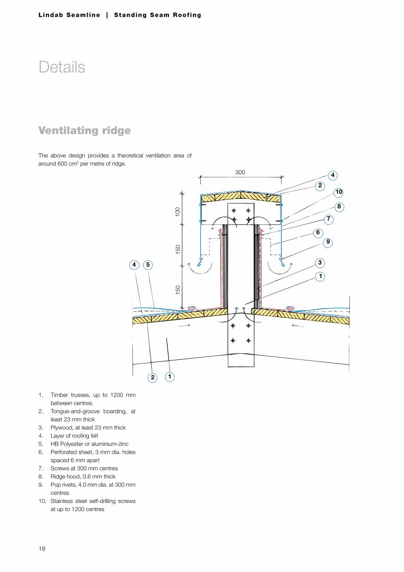
Ventilating ridge
1. Timber trusses, up to 1200 mm between centres.
2. Tongue-and-groove boarding, at least 23 mm thick
3. Plywood, at least 23 mm thick4. Layer of roofing felt5. HB Polyester or aluminium-zinc6. Perforated sheet, 3 mm dia. holes
spaced 6 mm apart7. Screws at 300 mm centres8. Ridge hood, 0.6 mm thick9. Pop rivets, 4.0 mm dia. at 300 mm
centres10. Stainless steel self-drilling screws
at up to 1200 centres
The above design provides a theoretical ventilation area of around 600 cm2 per metre of ridge.
4
102
8
7
6
9
3
1
4 5
12
30010
015
015
0
Details
19
Lindab Seamline | Standing Seam Roof ing
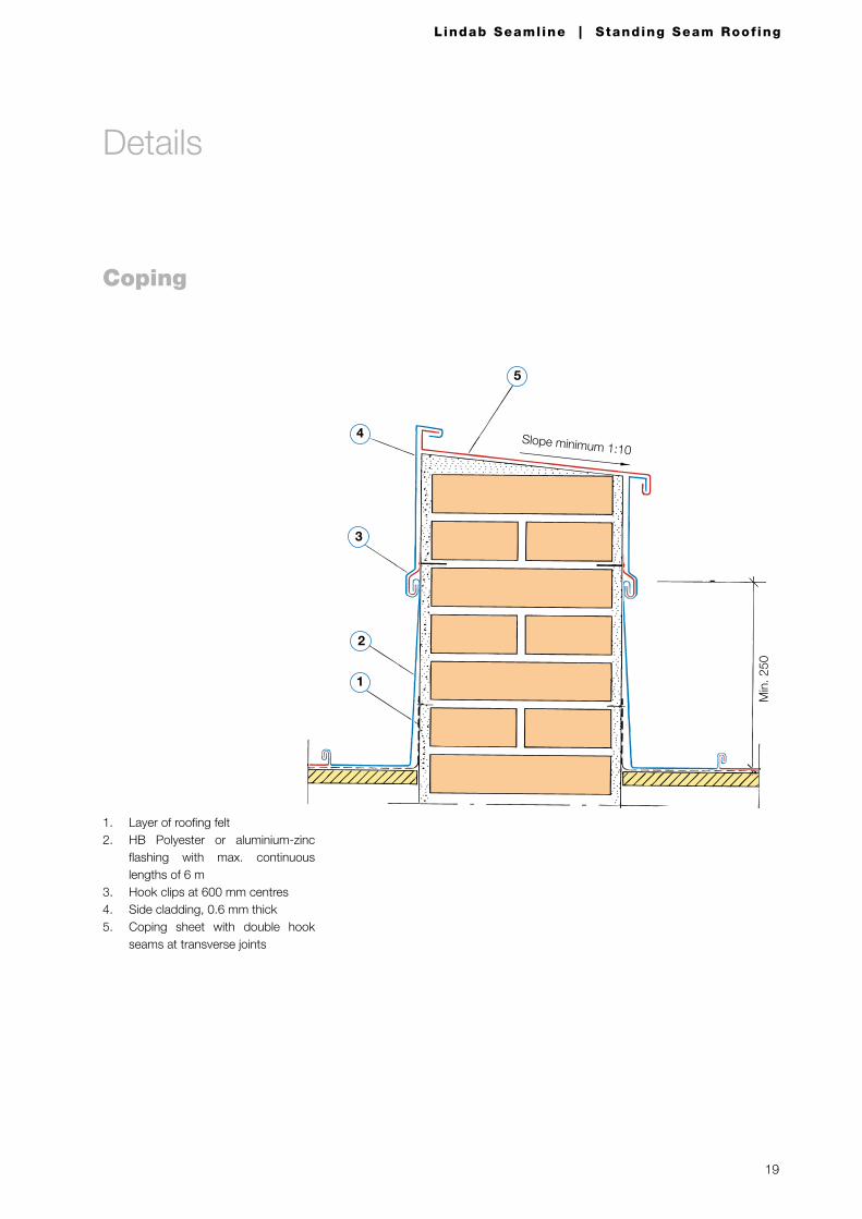
1. Layer of roofing felt2. HB Polyester or aluminium-zinc
flashing with max. continuous lengths of 6 m
3. Hook clips at 600 mm centres4. Side cladding, 0.6 mm thick5. Coping sheet with double hook
seams at transverse joints
Coping
5
4 Slope minimum 1:10
2
3
1
Min
. 250
Details
20
Lindab Seamline | Standing Seam Roof ing
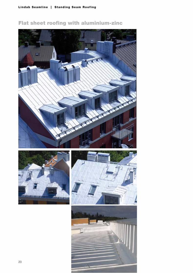
Flat sheet roofing with aluminium-zinc
21
Lindab Seamline | Standing Seam Roof ing
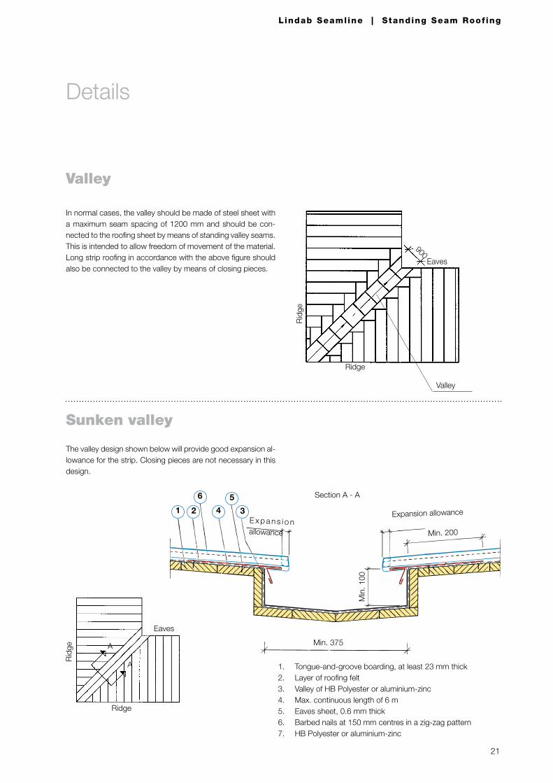
Sunken valley
1. Tongue-and-groove boarding, at least 23 mm thick2. Layer of roofing felt3. Valley of HB Polyester or aluminium-zinc 4. Max. continuous length of 6 m5. Eaves sheet, 0.6 mm thick6. Barbed nails at 150 mm centres in a zig-zag pattern7. HB Polyester or aluminium-zinc
The valley design shown below will provide good expansion al-lowance for the strip. Closing pieces are not necessary in this design.
Valley
In normal cases, the valley should be made of steel sheet with a maximum seam spacing of 1200 mm and should be con-nected to the roofing sheet by means of standing valley seams. This is intended to allow freedom of movement of the material. Long strip roofing in accordance with the above figure should also be connected to the valley by means of closing pieces.
3
5
1 2 4
6
Expansion allowance
Min. 200
Min
. 100
Min. 375
Section A - A
E x p a n s i o n allowance
Eaves
Ridge
Rid
ge
A
A
Eaves
900
Ridge
Rid
ge
Valley
Details
22
Lindab Seamline | Standing Seam Roof ing
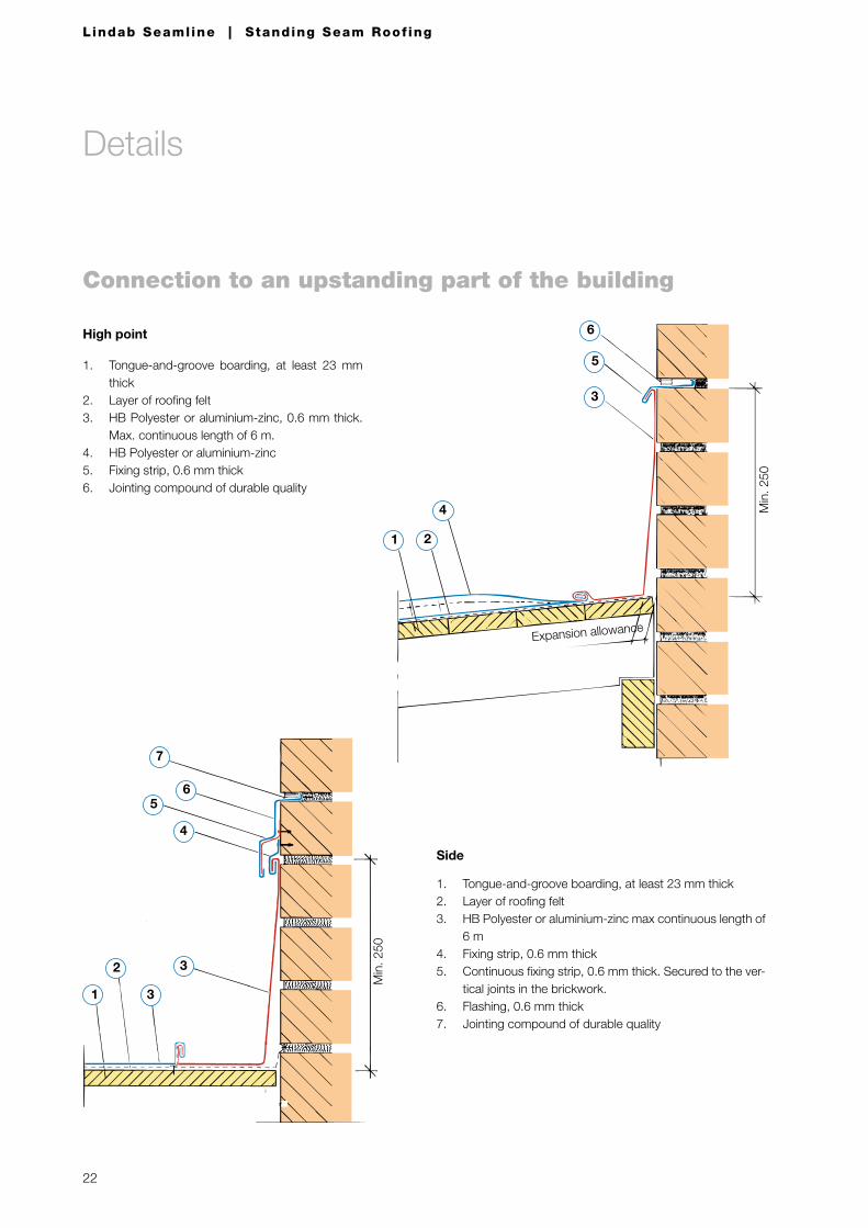
Connection to an upstanding part of the building
Side
1. Tongue-and-groove boarding, at least 23 mm thick2. Layer of roofing felt3. HB Polyester or aluminium-zinc max continuous length of
6 m4. Fixing strip, 0.6 mm thick5. Continuous fixing strip, 0.6 mm thick. Secured to the ver-
tical joints in the brickwork.6. Flashing, 0.6 mm thick7. Jointing compound of durable quality
High point
1. Tongue-and-groove boarding, at least 23 mm thick
2. Layer of roofing felt3. HB Polyester or aluminium-zinc, 0.6 mm thick.
Max. continuous length of 6 m.4. HB Polyester or aluminium-zinc5. Fixing strip, 0.6 mm thick6. Jointing compound of durable quality
4
1 2
Expansion allowance
Min
. 250
6
5
3
2
3
3
1
Min
. 250
7
65
4
Details
23
Lindab Seamline | Standing Seam Roof ing
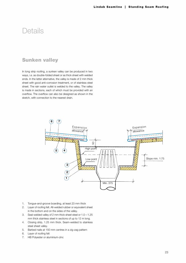
Sunken valley
In long strip roofing, a sunken valley can be produced in two ways, i.e. as double-folded sheet or as thick sheet with welded ends. In the latter alternative, the valley is made of 2 mm thick sheet with good anti-corrosion treatment, or of stainless steel sheet. The rain water outlet is welded to the valley. The valley is made in sections, each of which must be provided with an overflow. The overflow can also be designed as shown in the sketch, with connection to the nearest drain.
1
2
3
45
76
50
High point
Low point
Expansion
allowance
Min. 375
Slope min. 1:75
Expans ion allowance
1. Tongue-and-groove boarding, at least 23 mm thick2. Layer of roofing felt. All-welded rubber or equivalent sheet
in the bottom and on the sides of the valley.3. Seal-welded valley of 2 mm thick sheet steel or 1.0 – 1.25
mm thick stainless steel in sections of up to 12 m long.4. Closing strip, 1.25 mm thick. Seam-welded to stainless
steel sheet valley.5. Barbed nails at 150 mm centres in a zig-zag pattern6. Layer of roofing felt7. HB Polyester or aluminium-zinc
Details
24
Lindab Seamline | Standing Seam Roof ing
Details
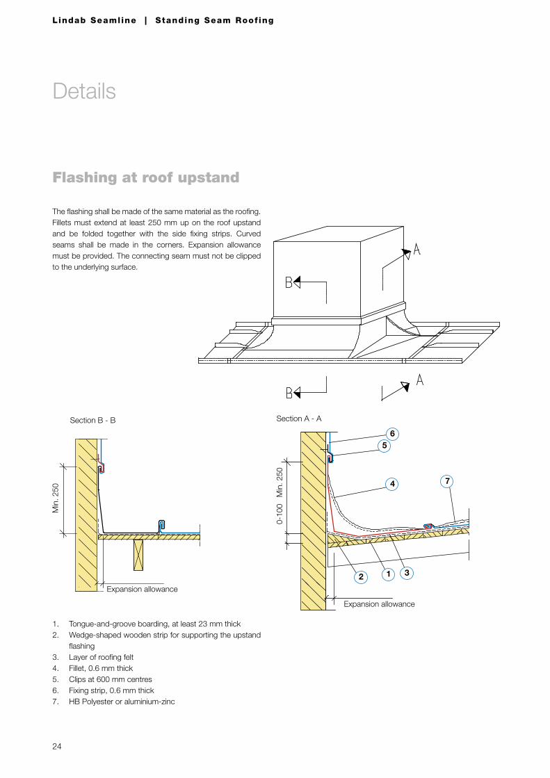
Flashing at roof upstand
The flashing shall be made of the same material as the roofing. Fillets must extend at least 250 mm up on the roof upstand and be folded together with the side fixing strips. Curved seams shall be made in the corners. Expansion allowance must be provided. The connecting seam must not be clipped to the underlying surface.
Section A - A
6
4 7
2 1 3
Min
. 250
5
Expansion allowance
0-10
0
1. Tongue-and-groove boarding, at least 23 mm thick2. Wedge-shaped wooden strip for supporting the upstand
flashing3. Layer of roofing felt4. Fillet, 0.6 mm thick5. Clips at 600 mm centres6. Fixing strip, 0.6 mm thick7. HB Polyester or aluminium-zinc
Min
. 250
Section B - B
Expansion allowance
25
Lindab Seamline | Standing Seam Roof ing
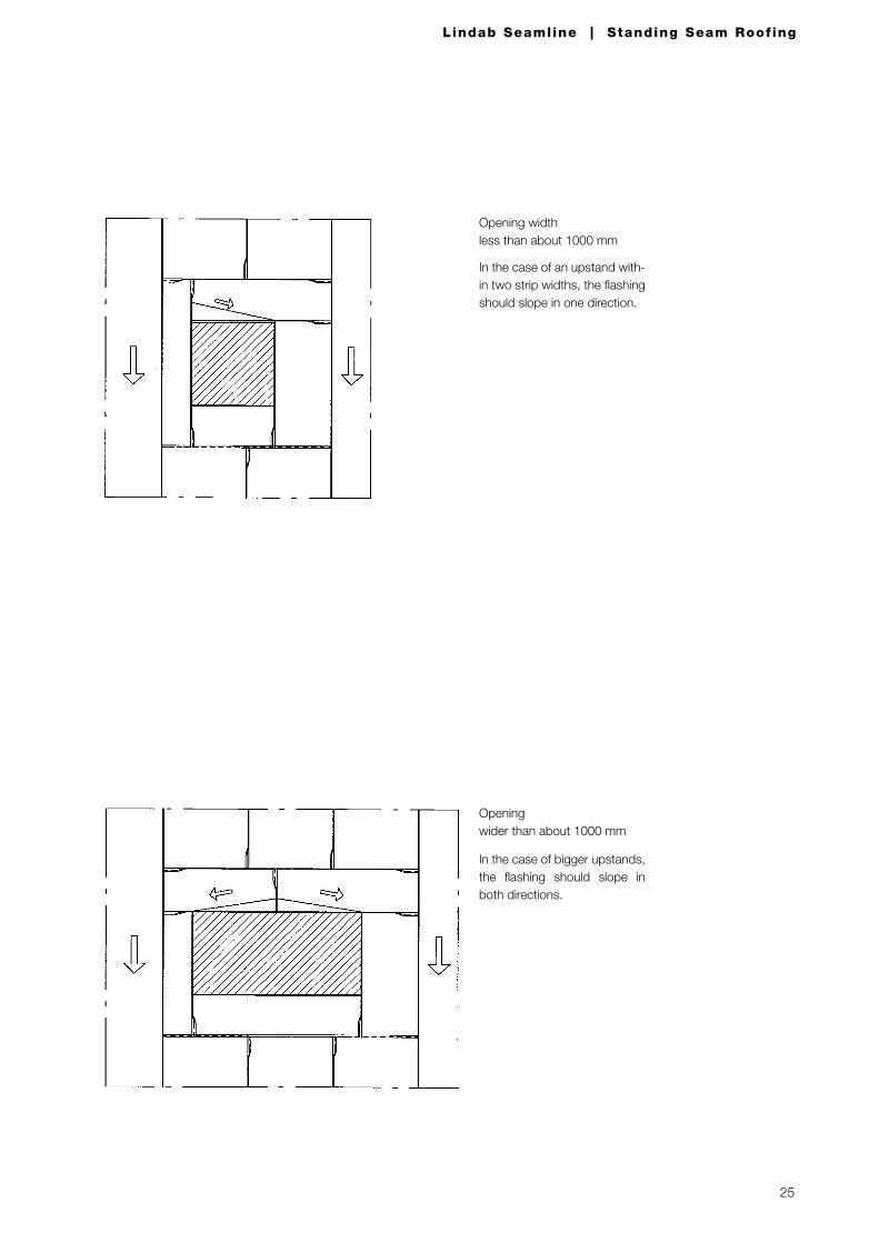
Opening width less than about 1000 mm
In the case of an upstand with-in two strip widths, the flashing should slope in one direction.
Opening wider than about 1000 mm
In the case of bigger upstands, the flashing should slope in both directions.
26
Lindab Seamline | Standing Seam Roof ing
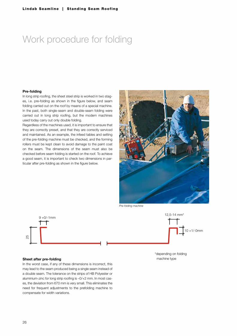
Work procedure for folding
Pre-foldingIn long strip roofing, the sheet steel strip is worked in two stag-es, i.e. pre-folding as shown in the figure below, and seam folding carried out on the roof by means of a special machine.In the past, both single-seam and double-seam folding were carried out in long strip roofing, but the modern machines used today carry out only double folding.Regardless of the machines used, it is important to ensure that they are correctly preset, and that they are correctly serviced and maintained. As an example, the infeed tables and setting of the pre-folding machine must be checked, and the forming rollers must be kept clean to avoid damage to the paint coat on the seam. The dimensions of the seam must also be checked before seam folding is started on the roof. To achieve a good seam, it is important to check two dimensions in par-ticular after pre-folding as shown in the figure below.
Sheet after pre-foldingIn the worst case, if any of these dimensions is incorrect, this may lead to the seam produced being a single seam instead of a double seam. The tolerance on the strips of HB Polyester or aluminium-zinc for long strip roofing is –0/+2 mm. In most cas-es, the deviation from 670 mm is very small. This eliminates the need for frequent adjustments to the prefolding machine to compensate for width variations.
10 +1/-0mm
9 +0/-1mm
25
12,5-14 mm*
*depending on folding machine type
Pre-folding machine
27
Lindab Seamline | Standing Seam Roof ing
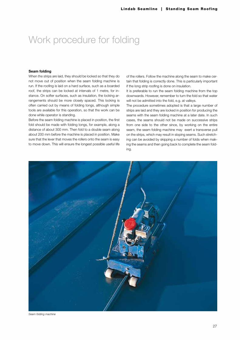
Seam foldingWhen the strips are laid, they should be locked so that they do not move out of position when the seam folding machine is run. If the roofing is laid on a hard surface, such as a boarded roof, the strips can be locked at intervals of 1 metre, for in-stance. On softer surfaces, such as insulation, the locking ar-rangements should be more closely spaced. This locking is often carried out by means of folding tongs, although simple tools are available for this operation, so that the work can be done while operator is standing.Before the seam folding machine is placed in position, the first fold should be made with folding tongs, for example, along a distance of about 300 mm. Then fold to a double seam along about 200 mm before the machine is placed in position. Make sure that the lever that moves the rollers onto the seam is easy to move down. This will ensure the longest possible useful life
of the rollers. Follow the machine along the seam to make cer-tain that folding is correctly done. This is particularly important if the long strip roofing is done on insulation.It is preferable to run the seam folding machine from the top downwards. However, remember to turn the fold so that water will not be admitted into the fold, e.g. at valleys.The procedure sometimes adopted is that a large number of strips are laid and they are locked in position for producing the seams with the seam folding machine at a later date. In such cases, the seams should not be made on successive strips from one side to the other since, by working on the entire seam, the seam folding machine may exert a transverse pull on the strips, which may result in sloping seams. Such stretch-ing can be avoided by skipping a number of folds when mak-ing the seams and then going back to complete the seam fold-ing.
Work procedure for folding
Seam folding machine
Lindab Seamline | Appl icat ion guide
Lindab Profile is a business area within the Lindab
Group that develops, manufactures, and markets
efficient, economical and aesthetic steel and sheet-
metal solutions for the building industry.
We offer everything from complete building systems to
individual building components for all types of housing,
as well as commercial and industrial buildings.
Lindab Profile is represented in over 25 countries
throughout Europe. Our head office is in Förslöv,
in the south of Sweden.
SE-269 82 BåstadPhone +46 (0)431 850 00www.lindab.com
Lindab Profile
Art
no
. 251
1 20
10-0
5-25

![LINDAB VENTILACE · Lindab Lindab LINDAB ‐ USNADŇUJEME VÝSTAVBU ‐ 0.01 ceník lindab v [Kč bez DPH] změny vyhrazeny ‐ 0.01 ‐ software ‐ 1 ‐ smart tools, doplňky ‐](https://img.pdfslide.net/doc/110x75/5b1f5fe77f8b9ae6418c9f23/lindab-lindab-lindab-lindab-usnadnujeme-vystavbu-001-cenik-lindab.jpg)