Embed Size (px)
Citation preview

Line Blind Valves Cam-Set®, Cam-Slide®,Cam-Goggle® & Stacey™

2
Safety First
Plant and personnel safety is a central theme for socially responsible and safety consciouscompanies. Following a series of fatal accidentsacross the globe, regulation now mandates certain minimum technical precautions in manyindustries. As a result the ability to isolate linesand ensure absolute downstream flow shut-offis essential.
Traditional ApproachTraditional line blinding methods such as inserting metal plates with a gasket betweenflanges assure safety, but are time consuming to open or close. Larger size blinds requirenumerous people or expensive equipment suchas cranes to change.
Time ConsumingIn the past, changing line blinds was consideredan onerous, time consuming and often danger-ous task.
The diagram below illustrates the time and manpower required to change a small size traditional line blind. Rotating the blind requiresthree men – two man to loosen the bolts andspread the line and the third to raise and rotatethe heavy spectacle plate. It could take up to 4 hours to rotate one blind – particulary whennuts and bolts are rusted.
For larger size blinds above 12 inches the changing process can take between 4 and 12 hours by a team of up to 6 men. As such,traditional line blinding techniques represent asignificant manpower, cost and safety factor.
Valve LimitationMany different types of valves are used to isolate pipelines. However, valves can and doleak. Downstream valve leakage can occurwithout the knowledge of plant personnel asthere is often no visual indication of failure. This scenario can at best lead to product waste orcontamination; at worst to the escape of toxicsubstances or a potentially explosive fire hazard.
Line Blind ProcessLine blinding is a process which ensures the total isolation or “blinding” of the downstreamflow within a pipeline. It is a common procedurein industries that store, forward or processhazardous chemical or petrochemical substancesor where the media may become unstable orpotentially dangerous during part of a process.
Line blinds often complement conventional valves used for isolation, in that they guaranteeabsolute and positive shut off to the downstream.Additionally, they provide a clear visual indicationof their actual open or closed status.
Solid plate between flanges 1/2” to 12”
1 to 4 hours by 3 menTools and spare parts

ConvenientThe Cam-Slide and Cam-Set are designedaround an internal cam system such that thebody flanges do not have to be spread and theadjacent piping does not have to move whenthe spectacle plate is changed. This simple fea-ture has enormous benefits, as piping move-ment can cause many problems – misalignmentof the piping, piping and vessel damage, andphysical injury to the men trying to move heavypiping.
Fast and Cost EffectiveThe Cam-Set/Slide is not only convenient butfast too. No bolts have to be loosened or remo-ved – often a difficult job if the bolts arerusted. The Cam-Set/Slide in comparison can be
changed in less thana minute for smallsizes and up to 3minutes for largersizes.
SchuF Fetterolf lineblind valves lead tosignificant cost andtime savings.
In comparison totraditional smallersize line blinds tosay twelve inches, the Cam-Set cansave between oneand four hours perman per job.
For larger sized blinds the time saving can beanything from 4 to 12 hours per man per job.
In addition to the time savings there are noadditional crane rental or usage fees required.
Materially SafeThe Cam-Set/Slide incorporates many materialand construction safety features. They are built tomeet or exceed ASME B16.5 standards. The thick-ness of the Cam-Set spectacle plate is equal to orgreater than that required byAPI 590 (ASME B16.48).
The tensile bolting area of theCam-Set/Slide is also equal toor greater than the tensile bol-ting area used in the flanges.
All of the body bolts are tackwelded so that they cannot be inadvertently removed orloosened.
The SchuF Fetterolf Cam-Set/Slide is easy to operate and safe – by design.
3
The Modern Alternative – The Cam-Set® & Cam-Slide®
Modern line blind systems such as the SchuFFetterolf Cam-Set or Cam-Slide change theinstallation of the blind into a one man operation taking only minutes to complete.Downstream safety is assured. In all sizes, theCam-Set/Slide makes line blinding convenient,fast and safe.
Convenient, Fast, Safe
Cam-Set/Slide® – Key Features
■ Absolute positive shut-off
■ Fast change
■ One man operation
■ No flange or line spreading
■ No special equipment required
■ Conforms / exceeds ASME B16.5 and API 590
■ Unique safety features
SchuF Cam-Set®
line blind 1/2” to 12”
30-60 seconds by 1 man
SAFE
IS N
OW E
ASY
Cam-Set DN 150 (6”), ASME 150 #

Operation
How the Cam-Set® and Cam-Slide® work
The internal cam system is actuated via a single screw (or handwheel) which is perpendicular to the axis of the pipe. When thescrew is rotated a movable inclined plane slides against a fixedinclined plane, moving the seal carrier away from the spectacleplate, thus freeing it to be moved to a new position.
The working of the Cam mechanism is illustrated below withdrawings of a Cam-Set. The Cam-Slide operates in exactly the same way with the exception that the spectacle plate slides from left to right or vice versa rather than swinging.
Note: the above drawings are presented in a cut away format in order to illustrate the internal functioning of the line blind.
2) Once the pipeline has been depressurised and drained, the Cam-Setcan be operated. In this picture the Cammechanism is retracted. The hand wheelhas been rotated counter clock-wise toachieve this. The spectacle plate is between the open and closed position.
3) In this picture the solid part of the spectacle plate has been inserted into the pipeline and flow to downstream is blocked by the line blind valve. Note that the cam mechanism is extended, thus locking the spectacle plate in place. The open part of the spectacle plate is now visibleindicating that the line is blocked.
1) In this picture, the orange coloured Cammechanism is closed. The solid part of thespectacle plate is above the pipe, visuallyindicating that the pipeline is open and thatfull flow through the line is available.
Line blind open
Line blind closed
Line blind valve in change position
4

8” Non Spill Cam-Slide Valve
Cam-Set® – SwingingLine Blind Valve – Model81FCThe Cam-Set (Model 81FC) is
a swing type of quick actingline blind. It has a three
bolt design and a trian-gular body. It is appropriate forapplications that
require fast blindingturnaround and that do
not exceed 1500# pressureclass. It can be made as a standard design up to 48”(DN 1200).
Cam-Slide® – Sliding Line Blind Valve –Model 81CSThe Cam-Slide (Model 81CS) is a quick actingsliding line blind. It has a multi bolt design and a rectangular body. It is appropriate for applica-tions that require fast blinding turnaround up to2500# pressure class. It can be made as a stan-dard design up to 64” (DN 1600).
Its multi bolt design enables a more compactbuild and lighter weight which make it ideal fortight spaces or reduced face to face dimensions.
The Cam product range includes the Cam-Set,Cam-Slide and Cam-Goggle valves. They all usethe unique and proven Cam mechanism.
Cam Product Range
5
Cam-Slide® Variants The Cam-Slide is also available as a non spill line blind (Model 81BS), in a compact design(Model 81CS Compact) with significantly reduced face to face dimensions and as a hightemperature model suitable for design
temperatures up to 800 ° C (Model 81HT).
Cam-Goggle® Valve –Model 81FGThe Cam-Goggle Valve is a further develop-ment of the Cam-Slidevalve, except it may beprovided with an enclosed body and isspecifically designed toconditions ratherthan to class. It isnormally recommen-ded for very largeblinding requirements(up to 120”) commonly
24” Cam-Slide Valve
8” Compact Cam-Slide

The Cam-Set/Slide comes with many options to match almost every requirement or operatingenvironment. This includes a wide variety of seals and seal materials.
All seals in a Cam-Set/Slide line blind can be replaced without removing the line blind fromthe piping system.
The sealing rings themselves are protected within the body of the blind, but can also beplaced in the spectacle plate should regularinspection be required.
Cam-Set® and Cam-Slide® Options
Coupled PipingThe Cam-Set/Slide can be used on close coupled piping such as tank farms, off shoreplatforms or ships and barges.
Corrosive EnvironmentThe Maritime industry is a good example of lineblind usage in a corrosive environment. Whenused aboard a ship or FPSO, a Sermetel coatingis frequently used to protect any carbon steelparts from corrosion due to the salt air atmos-phere. Likewise the stem is in a high alloy corro-sive resistant material, the hand wheel is bronzeand all bolting or wetted parts are in stainlesssteel.
Larger SizesAs the size of the line blind increases above 12inches and up to 48 inches or greater, the job ofswinging the spectacle plate can be cumbersomedue to the offset weight. In these instances aspecial counterweight can be added to theblind which maintains the easy and safe “OneMan Operation” benefits of the Cam-Set/Slidefor larger sizes.
Cam-Set DN 100 (4”), ASME 300 #
Cam-Set DN 500 (20”), ASME 150 # with spectacle plate support
Other options include:
■ Locking devices
■ Spectacle plate covers
■ Special coatings
■ Drain ports
■ Drain, purge and sampling valve combinations
■ Roller support for spectacle plates
■ Sealing ring in spectacle plate
■ Dual and triple sealing rings
■ Pneumatic, electric or hydraulic actuation
■ Counterweights
■ Diverse selection of o-rings
Line blinding using the Cam-Set/Slide®
can be achieved by one man on one sideof the pipeline, without the necessity ofmultiple spreader bolts or a crane.
6
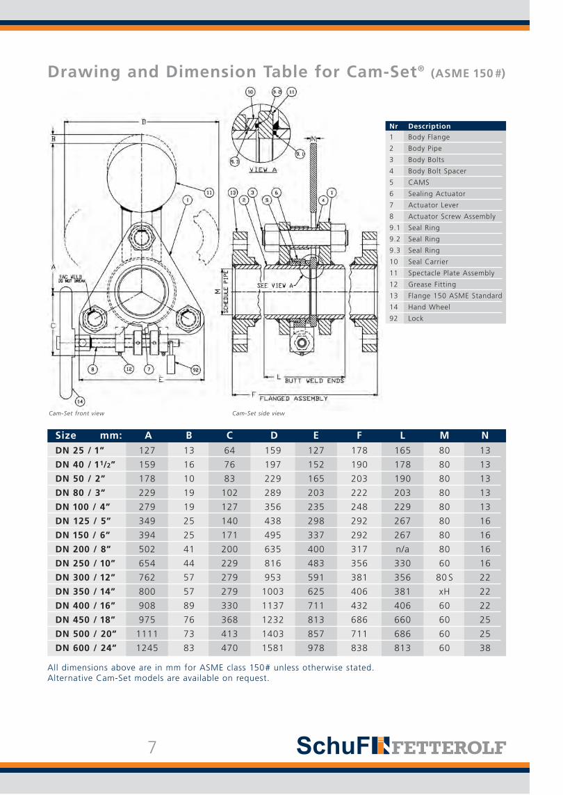
DN 25 / 1” 127 13 64 159 127 178 165 80 13
DN 40 / 11/2” 159 16 76 197 152 190 178 80 13
DN 50 / 2” 178 10 83 229 165 203 190 80 13
DN 80 / 3” 229 19 102 289 203 222 203 80 13
DN 100 / 4” 279 19 127 356 235 248 229 80 13
DN 125 / 5” 349 25 140 438 298 292 267 80 16
DN 150 / 6” 394 25 171 495 337 292 267 80 16
DN 200 / 8” 502 41 200 635 400 317 n/a 80 16
DN 250 / 10” 654 44 229 816 483 356 330 60 16
DN 300 / 12” 762 57 279 953 591 381 356 80 S 22
DN 350 / 14” 800 57 279 1003 625 406 381 xH 22
DN 400 / 16” 908 89 330 1137 711 432 406 60 22
DN 450 / 18” 975 76 368 1232 813 686 660 60 25
DN 500 / 20” 1111 73 413 1403 857 711 686 60 25
DN 600 / 24” 1245 83 470 1581 978 838 813 60 38
All dimensions above are in mm for ASME class 150# unless otherwise stated. Alternative Cam-Set models are available on request.
Size mm: A B C D E F L M N
Nr Description
1 Body Flange
2 Body Pipe
3 Body Bolts
4 Body Bolt Spacer
5 CAMS
6 Sealing Actuator
7 Actuator Lever
8 Actuator Screw Assembly
9.1 Seal Ring
9.2 Seal Ring
9.3 Seal Ring
10 Seal Carrier
11 Spectacle Plate Assembly
12 Grease Fitting
13 Flange 150 ASME Standard
14 Hand Wheel
92 Lock
Drawing and Dimension Table for Cam-Set® (ASME 150 #)
Cam-Set front view Cam-Set side view
7

All dimensions above are in mm for ASME class 150# unless otherwise stated. Alternative Cam-Slide models are available on request.
Nr Description 1 Body
2 Body Pipe
3 Body Bolts
4 Body Bolt Spacer
5 CAMS
6 Sealing Actuator
7 Actuator Lever
8 Actuator Screw Assembly
9.1 Seal Ring
9.2 Seal Ring
9.3 Seal Ring
10 Seal Carrier
11 Spectacle Plate Assembly
12 Grease Fitting
13 Flange 150 ASME Standard
14 Handwheel
92 Lock
Drawing and Dimension Table for Cam-Slide® (ASME 150 #)
Cam-Slide front view Cam-Slide side view
8
Size Size A1 A2 D E F G L M N WeightAME DIN Kg / Lbs
1” DN 25 134 114 89 279 177,8 [7.00”] 51 166 1” SCH. 80 13 15/3311/2” DN 40 159 140 102 323 190 [7.50”] 178 178 11/2” SCH. 80 13 25/55
2” DN 50 184 165 115 366 203,2 [8.00”] 77 192 2” SCH. 80 13 29/64
3” DN 80 263 251 170 268 222,3 [8.75”] 65 203,2 3” SCH. 80 12,7 35/77
4” DN 100 335 321 200 431 247,7 [9.75”] 90 228,7 4” SCH. 80 12,7 56/123
5” DN 125 388 371 228 462 292,1 [11.50”] 266,7 266,7 5" SCH. 80 14 75/165
6” DN 150 440 420 255 493 292.1 [11.50"] 108 266,7 6" SCH. 80 15,9 97/214
8” DN 200 510 497 300 573 317.5 [12.50"] 128 292,1 8" SCH. 80 15,9 115/254
10” DN 250 610 590 345 625 355.6 [14.00"] 163 330 10" SCH. 60 15,9 190/419
12” DN 300 725 702 410 750 381 [15.00"] 188 357 12" SCH. 80S 22 270/595
14” DN 350 778 761 470 816 406.4 [16.00"] 213 381 14" SCH. 80 22,2 420/926
16” DN 400 783 761 486 931 432 [17.00"] 251 406 16" SCH. 60 22,4 496/1093
18” DN 450 881 856 547 1047 686 [27.00"] 282 660 18" SCH. 60 25 568/1230
20” DN 500 894 894 625 1250 711 [28.00"] 308 686 20" SCH. 60 26 1208/2663
24” DN 600 1073 1073 750 1500 838.2 [33.00"] 338 813 24" SCH. 60 31,8 1450/3197
28” DN 700 1252 1252 875 1750 914.4 [36.00"] 394 885 28" SCH. 30 37 1692/3730
30” DN 750 1341 1341 938 1875 868.8 [34.25"] 423 1016 30" SCH. 20 40 1812/3996

Cam-Goggle® Valve
Goggle valves are very similar to line blind valves. They are generally used in Gas BlastFurnace or very low pressure applications (lessthan 1 bar), often have enclosures and can bemade up to 120” (DN 3000).
Open and Closed Models
There are two types of Cam-Goggle valve avai-lable – open and enclosed types. The opentype is for all intents and purposes no differentthan a line blind valve with the exception thatit may be specified according to operating conditions rather than to ASME pressure class.This is an important factor, particularly forlarge size valves where a valve built to classcan become very heavy. The Goggle valve incomparison may be built exactly to the opera-
ting pressure requirements – e.g. 75 psi. This reflects the engineering principal that bodyand spectacle plate wall thickness increases inaccordance with pressure.
Enclosed Cam-Goggle®
Enclosed Cam-Goggle valves enable the specta-cle plate to be changed without releasing anymedium to atmosphere. They are man safe and100% gas tight to the atmosphere. The enclosure is supplied with a venting systemto allow any gases to be removed safely. The above picture shows the Cam-Goggle valve
48" Cam-Goggle Valve in closed position
Cam-Goggle® – Features
■ Man Safe Isolation
■ 100% shut off of media flow
■ Non line spreading Cam Design
■ Dual plate seal rings for added safety
■ Spectacle plate lift mechanism to ensure smooth plate transition
■ Split enclosure on rails for ease of maintenance
Enclosed Cam-Gogglein the closed position. The spectacle plate isshown in orange for illustrative purposes. Thevalve is made up of three main parts – the cen-tral core body, the enclosure “tanks” on bothsides and the rail beam above. The core bodyhas two vent ports in order to vent gases toatmosphere if and when required.
9

Cam-Slide® Overview
48" Cam-Goggle Valve with enclosures retracted
Options
■ Rail beam option for assembly
■ Bevel gearbox manual actuation, electric, pneumatic or hydraulic actuation
■ Venting to atmosphere of totally enclosed type in closed position
■ Optional – viewports to verify open /closed position
■ A high level of customisation is available upon request
OperationSpectacle plate movement is achieved in two simple steps - the first handwheel operates the internal cam mechanism. The hand wheel releases the pressure on the seal tight internal o-ring which in turn enables the second gear actuated hand wheel to move the spectacle plate from the closed to the open position. For illustrative purposes the right hand enclo-sure or tank is shown without the front platewall and the spectacle plate is coloured yellow.
The tank enclosures are mounted on a rail beamand rollers which enables them to be pushedback for ease of maintenance.However, some limited maintenance can beachieved in the closed position.
The Cam-Goggle can be actuated electrically orhydraulically or a combination of both. Fetterolf can also supply compact hydraulic unitsfor power supply.
10
48"Cam-Goggle Valve in the open position

Cam-Set®, Cam-Slide®, Cam-Goggle® Specifications
Size DN 10-15 (1/2") to DN 1200 (48") Cam-Goggle to DN 2500 (100”)
Pressure class ASME 150#, 300#, 600# Cam-Slide to ASME 2500#
Body material Carbon steel 316 stainless steel; others on request
Spectacle Plate Stainless steel Duplex, Hastelloy, Alloy 20, Inconel, Nickel, Monel & Titanium
Stem Carbon steel Monel
Bolting Carbon steel 316 stainless steel; others on request
O-Rings Viton, Buna-N Aflas, Teflon, Nordel, Chemraz, Kalrez and others depending on application
Temperature 232 ° C / 450 ° F Up to 800 ° C / 1472 ° F with special design Cam-Slide
Pipe Connection Butt weld end Flanged
Drain/Purge n/a Line drain, purge or sampling valve Connection combinations are possible
Coatings Standard paint Epoxy, Polyurethane, Sermetel, Ceramic and many others
Reduced Face to Face n/a Yes with comapct Cam-Slide modelDimensions
Counterweight or n/a Yes; recommended on large sizesroller support
Locking device n/a Yes
Standards/Certification ASME, DIN, CRN, ISO, PED NACE
Actuation Hex nut Hand wheel, pneumatic, hydraulic
Description Standard Options
Cam-Set DN 150 (6”), ASME 150#, side view
Engineering Standards
ASME Standard Description
B16.5 Pipe flanges and flanged fittings
B16.34 Valves - flanged, threaded and welding end
B 31.1 Power piping
ASTM F1020-86 Line Blind Valves for Marine Applications
ASME B & PV Code Description (Boiler & Pressure Vessel Code)
Section 2 Material
Section 8 Rules for construction of pressure vessels
Section 9 Welding and brazing qualifications
API Standard Description
API 590 (now ASME 16.48) Steel Line Blanks for Refining
API 598 Valve inspection and testing
API 2217 Guidelines for confined space work in the Petroleum Industry
Others Description
ISO 9001 Quality management system
NACE MR0175 Sulfide stress cracking and stress corrosion
11

12
Stacey™ Line Blind System
The Stacey is a modern line spreading line blindsystem. It has a number of advantages overconventional blind plates such as ease of use,one to two man operation, absolute shut off,and is relatively quick to use. In this respect theStacey can be changed in five to ten minutesdepending on size and can break any crustbuild-up in or on the blind.
Stacey spectacle blinds are available in allASME pressure ratings, a wide range of sizes
Stacey, side view Three bolt Stacey, front view Five bolt Stacey, front view
Stacey DN 850 (34”) with counterweight
and a wide range of materials. The multiplebolts expand the list of possible sealing materi-als for service temperatures from cryogenic toelevated. They are a viable alternative to theCam-Set when flexibility and ease of use areless important.
Operation
With the Stacey blind 3, 5, 7 or 9 bolts (depend-ing on size) are loosened in even quarter turnsfor one to two revolutions, automatically spread-ing the body flanges apart far enough to rotatethe spectacle plate to its desired position –fully open or closed.
Retighten the bolts evenly and the change iscomplete. Bolt heads are drilled to receive ashort piece of steel bar or pipe – no specialtools are required.
ApplicationsThe Stacey is ideal for certain types of applica-tions where the line blind must be both largeand have a high pressure rating (ASME 900 andabove). Similarly several applications that requirethe line blind to operate in a severe or powderyenvironment, such as in the cement or aluminaindustry, are better served by the Stacey.

13
Dimension Table for Stacey™
150# 165 178 178 203 203 203 229 229A 300# 165 178 178 222 222 241 279 279
600# 191 210 210 241 241 273 292 292
150# 197 219 219 241 241 305 381 381B 300# 197 219 219 241 241 343 406 406
600# 216 254 254 305 305 406 457 457
150# 76 76 76 102 102 114 152 152C 300# 76 76 76 102 102 130 152 152
600# 89 102 102 121 121 140 165 165
150# 67 76 76 92 92 114 149 149D 300# 67 76 76 92 92 121 152 152
600# 73 79 79 102 102 127 171 171
150# 152 197 197 241 241 298 381 381E 300# 152 197 197 241 241 298 381 381
600# 165 191 191 248 248 330 445 445
150# 178 241 241 295 295 352 464 464F 300# 178 241 241 295 295 365 473 473
600# 203 248 248 318 318 406 546 546
G Drains n/a n/a 13 13 13 13 19 19
150# 273 302 302 340 340 352 403 403H 300# 286 311 311 378 378 410 473 473
600# 311 346 352 403 403 457 514 514
All dimensions are in mm unless otherwise stated. Dimensions for other Stacey models are available on request.
mm Class DN 25 / 1” DN 40 / 11/2” DN 50 / 2” DN 65 / 21/2” DN 80 / 3” DN 100 / 4” DN 125 / 5” DN 150 / 6”
150# 254 254 279 305 381 432 483 610A 300# 368 381 406 419 432 - - -
600# 381 406 - - - - - -
150# 419 508 565 635 711 787 851 1.067B 300# 464 559 622 699 787 - - -
600# 521 610 - - - - - -
150# 165 203 229 254 324 356 387 479C 300# 171 248 305 318 356 - - -
600# 229 267 - - - - - -
150# 171 213 244 270 298 330 359 454D 300# 178 213 251 273 305 - - -
600# 191 229 - - - - - -
150# 451 552 648 737 826 914 1003 1245E 300# 476 575 673 737 838 - - -
600# 508 622 - - - - - -
150# 578 711 832 927 1067 1168 1270 1581F 300# 597 737 851 940 1067 - - -
600# 635 787 - - - - - -
G Drains 19 25 25 25 25 25 25 25
150# 451 451 502 552 629 705 762 905H 300# 587 610 660 699 718 - - -
600# 641 705 - - - - - -
mm Class DN 200 / 8” DN 250 / 10” DN 300 / 12” DN 350 / 14” DN 400 / 16” DN 450 / 18” DN 500 / 20” DN 600 / 24”

SchuF Fetterolf Cam-Set/Slide and Stacey lineblind valves are commonly used in the most criti-cal applications: aboard tankers product cross contamination or accidental overboard dischargeassumes the proportions of a disaster; in chemi-cal and petrochemical plants, refineries and tankstorage farms; and where vessel entry is a problem. Power generating plants installthem upstream of equipment which will requirerepairs. Other important users include steel mills,cement manufacturing plants, and the pulp andpaper industry.
RefineryPetrobras, the leading state refinery in Brazil,uses the Cam-Set and Stacey line blind systemextensively.
They are used in several process areas in therefinery including:
■ Gas flare applications
■ Hydrocracking units
■ Catalytic cracking unit
■ Delayed coking
■ Storage tanks
Over 200 SchuF Fetterolf line blind valves havebeen installed. The refinery enjoys a strong reputation for good maintenance and safety procedures.
Tank TerminalsGATX Terminal Corporation is one of the worldsleading port, terminal, rail and ship operators. Attheir Philadelphia and New Jersey sea terminals,they have replaced all traditional blinds with theCam-Set. They are used on 16” lines to ensuretotal isolation between different tanks in orderto prevent product cross contamination.Traditional line blinds could not be used as linespreading dented and buckled the tank walls.
14
Industry Case Studies for Cam Product Range & Stacey™
The customer has commented: “With the Cam-Set, it is a cinch to quickly change fromclosed to open by turning only one bolt and not moving any piping!”.
Other major tank farm customers include –Vopak, Oiltanking and Emarat.
Offshore & Maritime
SchuF Fetterolf has been chosen for severaloffshore projects. Used around compressors onoil platforms and oil refining and processingships, the Cam-Slide and Stacey are ideal due totheir ability to provide higher pressure ratingsand/or large sizes up to 54”. The high quality construction and safety standards of the Cam-Slide and Stacey are greatly respected in this industry, especially asthey are easy to operate in stormy weather.
The special maritime Cam-Set/Slide has beeninstalled by many marine, engineering and shipping companies including: Chevron Marine,Modec, Exxon, Pratt & Whitney, BP, Hyundai,Samsung and Ocean Ships to name a few.
Steel Industry
A rugged sturdy design and absolute safe shutoff are critical factors for the steel industry. Line blinds installed in and around coke ovengas and blast furnace fuel lines have to beabsolutely secure despite tremendous pressureon the blinds.
The SchuF Fetterolf Cam-Set is ideal for theseapplications due to its attention to safety factors. The spectacle plate thickness is specified to exceed API standards, there are two o-rings sealing the plate and the body bolts are tack welded to ensure that they arenot removed due to operator error. These features have led steel mill customerssuch as Kobe Steel USA, Corus, AK SteelCorporation, Arcelor Mittal, Tata and others to choose SchuF Fetterolf.

■ Alcoa
■ BASF
■ Bayer Thai
■ BHP Billiton
■ BP
■ Bushan Steel
■ California Steel Industry
■ Celanese
■ Chevron Marine
■ Cofely Gas de France
■ Conoco Philips
■ Daikin Chemical
■ Degussa
■ Dialog
■ Dow Chemical
■ DuPont
■ Eastman Chemicals
■ Emirates Gas
■ Evonik
■ Exxon Oil & Chemical
■ Fluor
■ Formosa Petrochemicals
■ GATX Terminals
■ General Electric
■ Hyundai Shipbuilding
■ Merck & Co.
■ Mexichem
■ Modec
■ Monsanto
■ Nestlé
■ Norsk Hydro
■ Northrop-Grumman Shipyard
■ Paul Wurth
■ Petrobras Brazil
■ Petrochem
■ PPG Industries
■ Procter & Gamble
■ Pfizer
■ Rhone Poulenc
■ Sabic
■ Sandoz
■ Shell Oil
■ TATA Steel
■ Texaco Oil & Marine
■ Toyo USA
■ Tupras Ismit Refinery
■ US Navy
■ Venezuela Cement
■ Vopak Horizon
■ Wallen Ship Management
■ Zeneca
SchuF Fetterolf Valve Portfolio
15
OtherProducts
Lift Plug On-Off Isolation
Line SamplingValve
Angle ControlValve
Pistom / RamBottom Outlet
MultiportDiverter Valve
Y-Globe Valve
Line Blinding Systems
Lift PlugSwitching
Screw-InSampling Valve
Globe ControlValve
Disc loweringBottom Outlet
Lift PlugDiverter Valve
Spray RinseValve
Lift PlugBypass
Coker IsoPlug
Coker SwitchPlug
Coker ControlPlug
Coker Quench Valve
SubmersedSampling Valve
Wafer ControlValve
Disc risingBottom Outlet
ChangeoverValve
High PressureAngle Valve
WaferSampling Valve
SamplingSystems
BackpressureControl Valve
AutomaticRecirculation
Valve
ChangeoverCombination
Valve
EmergencyTank Shut-offValves (TESO)
Steam InjectionValve
In-LineValves
Sampling Valves
Control Valves
BottomOutletValves
Diverter &Changeover
Valves
Coker Valves
SchuF Fetterolf has delivered over one million valves during its 100 year history to a wide variety of industries in over 50 countries worldwide.
Headquartered near Frankfurt in Germany, the com-pany has additional design and manufacturing centresin India, Ireland, Italy, the UK and the USA.
The SchuF group has sales and agent officescovering almost every country in the world.
We manufacture valve products that control,isolate, divert, and sample liquids, gases, powders, and slurries. Our product range ofengineered, customised valves includes:
Cam-Set DN 150 (6”), ASME 150#
Sample Cam-Set®, Cam-Slide® and Stacey™ Client List:
SAFE
IS N
OW F
AST

Worldwide
w w w. s c h u f . c o m · w w w. s c h u f . d e
Fetterolf Corporation phone: +1 610 584-1500 [email protected]
SchuF (USA) Inc. phone: +1 843 8813345 [email protected]
US
A SchuF Valve Technology GmbH phone: +353 21 4837000 [email protected]
IRE
LA
ND
SchuF-Armaturen und Apparatebau GmbH phone: +49 6198 571 100 [email protected]
GE
RM
AN
Y
La Tecnovalvo S.r.l. phone: +39 023 503 [email protected]
ALY SchuF Speciality Valves
India Pvt. Ltd. phone: +91 421 226 4600 [email protected]
DIA
Your Local Agent:
Your Sales Channel:
SchuF (UK) Ltd. phone: +44 203 355 2012 [email protected]
UN
ITE
D K
ING
DO
M
SchuF Benelux B.V. phone +31 25 12 34 448 [email protected]
SchuF Middle East F.Z.C. phone: +971 4 35 28 095 [email protected]
SchuF South East Asia Pte. Ltd. phone +31 620 62 66 64 [email protected]
SchuF Valves China Ltd. phone +86 27 83 316 569 [email protected]
PB_EU_SchuF_LineBlindValves_R5_2020-03