Embed Size (px)
Citation preview
Project Report of
EE 318 Electronic Design Lab-I
Line Following Robot using CMUCam
Smit P. Parmar (06007007)<[email protected]> Anand Malpani (06007009)<[email protected]>
Brijendra Singh (06007025)<[email protected]>
Faculty Adviser: V. Rajbabu Course Instructor: Vivek Agarwal / V. K. Tandon
Electrical Engineering Department
IIT Bombay
April 2009

Abstract
In our day-to-day life we often encounter the need for a machine or a system that can be autonomous and do our chores. On a long drive we often get tired and wish if our leg could have some rest instead of being on the accelerator for all the time, our hands being free instead of continuously controlling the steering wheel. To track an object of importance we need not always have to keep an eye on it. No need to push the trolley at a factory or a superstore or the baby vehicle. All these and many more problems can be solved using a line follower which is based on the principle of image processing. In this project we have tried our hands to make a working line follower bot which uses the principle of image processing. It is different than the normal line followers in the sense that it uses image processing instead of photodiode sensors thus giving it an advantage of seeing the future (i.e. the oncoming pattern of the line) and get ready to steer on that pattern. Another upper hand of this design is that it can follow any coloured line provided that the background has a slight contrast in colour. We have made use of the CMUCam that has an in-built processor for image processing.
1. Introduction
The machine is designed to detect and follow a line having a specific colour that has been fed to the camera beforehand (however can be changed using simple commands). The line colour and the background colour need to be sufficiently different. The images captured by the CMUCam are processed and the information is sent to the microcontroller (muc) which then controls the motion of the vehicle accordingly.
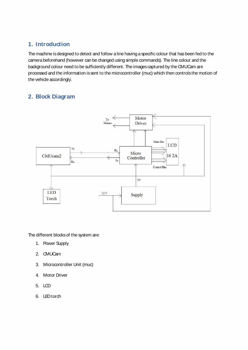
2. Block Diagram
The different blocks of the system are:
1. Power Supply
2. CMUCam
3. Microcontroller Unit (muc)
4. Motor Driver
5. LCD
6. LED torch
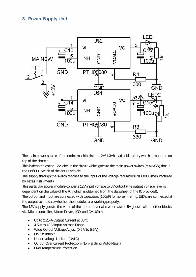
3. Power Supply Unit
The main power source of the entire machine is the 12V/1.3Ah lead acid battery which is mounted on top of the chassis. This is denoted as the 12V label in the circuit which goes to the main power switch (MAINSW) that is the ON/OFF switch of the entire vehicle. The supply through the switch reaches to the input of the voltage regulators PTH08080 manufactured by Texas Instruments. This particular power module converts 12V input voltage to 5V output (the output voltage level is dependent on the value of the Radj which is obtained from the datasheet of the IC provided). The output and input are connected with capacitors (100µF) for noise filtering. LED’s are connected at the output to indicate whether the modules are working properly. The 12V supply goes to the Vs pin of the motor driver also whereas the 5V goes to all the other blocks viz. Micro-controller, Motor Driver, LCD, and CMUCam.
Up to 2.25-A Output Current at 85°C 4.5-V to 18-V Input Voltage Range Wide-Output Voltage Adjust (0.9 V to 5.5 V) On/Off Inhibit Under-voltage Lockout (UVLO) Output Over current Protection (Non-latching, Auto-Reset) Over temperature Protection
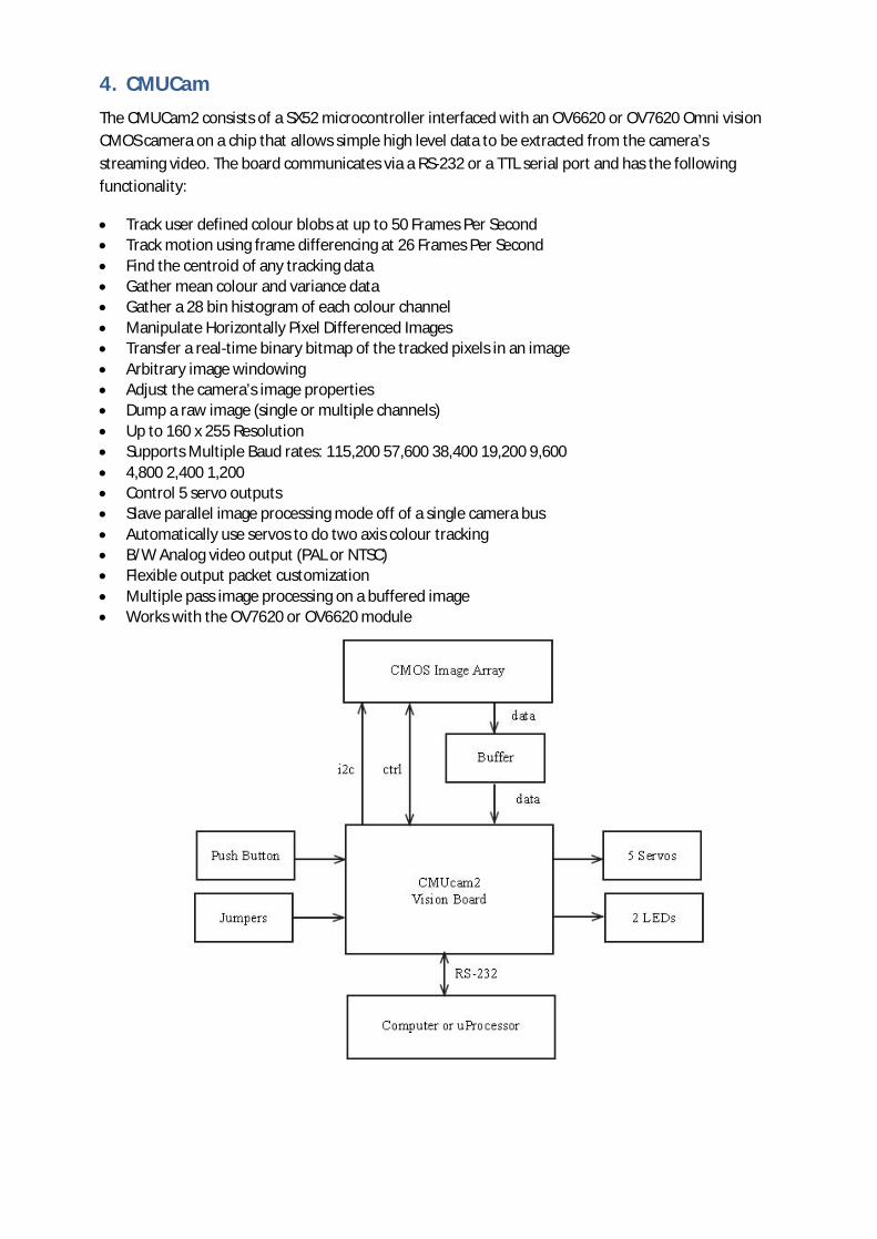
4. CMUCam
The CMUCam2 consists of a SX52 microcontroller interfaced with an OV6620 or OV7620 Omni vision CMOS camera on a chip that allows simple high level data to be extracted from the camera’s streaming video. The board communicates via a RS-232 or a TTL serial port and has the following functionality:
Track user defined colour blobs at up to 50 Frames Per Second Track motion using frame differencing at 26 Frames Per Second Find the centroid of any tracking data Gather mean colour and variance data Gather a 28 bin histogram of each colour channel Manipulate Horizontally Pixel Differenced Images Transfer a real-time binary bitmap of the tracked pixels in an image Arbitrary image windowing Adjust the camera’s image properties Dump a raw image (single or multiple channels) Up to 160 x 255 Resolution Supports Multiple Baud rates: 115,200 57,600 38,400 19,200 9,600 4,800 2,400 1,200 Control 5 servo outputs Slave parallel image processing mode off of a single camera bus Automatically use servos to do two axis colour tracking B/W Analog video output (PAL or NTSC) Flexible output packet customization Multiple pass image processing on a buffered image Works with the OV7620 or OV6620 module
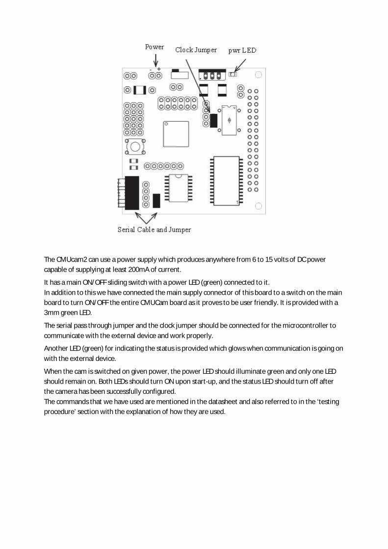
The CMUcam2 can use a power supply which produces anywhere from 6 to 15 volts of DC power capable of supplying at least 200mA of current.
It has a main ON/OFF sliding switch with a power LED (green) connected to it. In addition to this we have connected the main supply connector of this board to a switch on the main board to turn ON/OFF the entire CMUCam board as it proves to be user friendly. It is provided with a 3mm green LED.
The serial pass through jumper and the clock jumper should be connected for the microcontroller to communicate with the external device and work properly.
Another LED (green) for indicating the status is provided which glows when communication is going on with the external device.
When the cam is switched on given power, the power LED should illuminate green and only one LED should remain on. Both LEDs should turn ON upon start-up, and the status LED should turn off after the camera has been successfully configured. The commands that we have used are mentioned in the datasheet and also referred to in the ‘testing procedure’ section with the explanation of how they are used.
5. Microcontroller
We are using atmega8 of the AVR family from Atmel for the processing and controlling of the machine. Initially we were using atmega16 as the processor, but after testing it came to our knowledge that the former is also sufficient for our purpose. atmega8 has,
8K Bytes of In-System Self-programmable Flash program memory
512 Bytes EEPROM
1K Byte Internal SRAM
One 16-bit Timer/Counter with Separate Prescaler, Compare Mode, and Capture Mode
Byte-oriented Two-wire Serial Interface
Programmable Serial USART
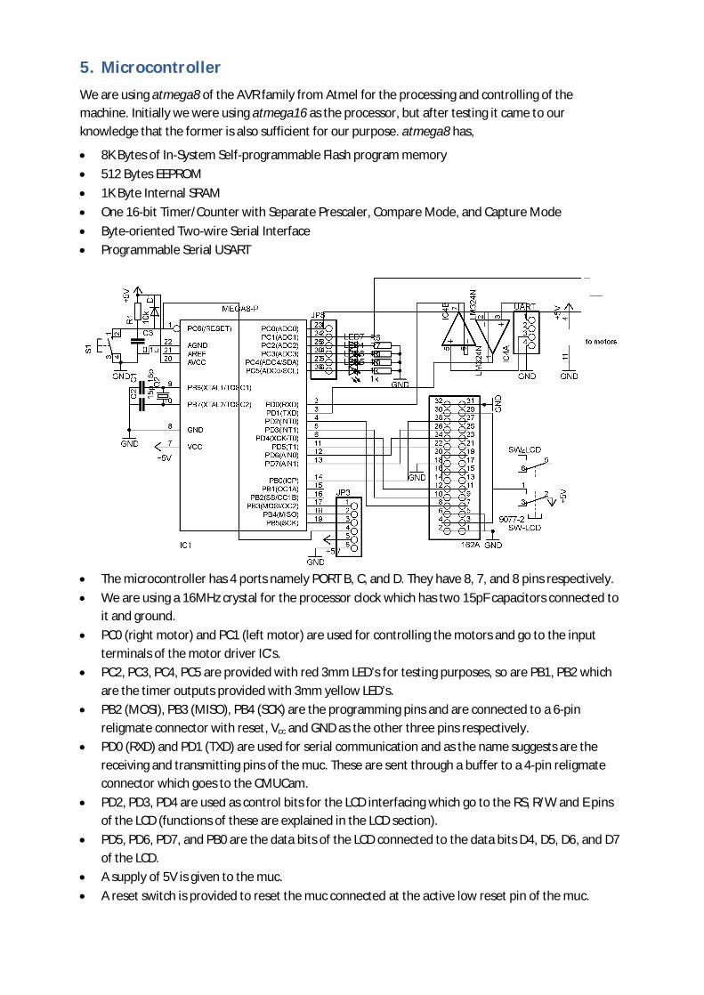
The microcontroller has 4 ports namely PORT B, C, and D. They have 8, 7, and 8 pins respectively.
We are using a 16MHz crystal for the processor clock which has two 15pF capacitors connected to it and ground.
PC0 (right motor) and PC1 (left motor) are used for controlling the motors and go to the input terminals of the motor driver IC’s.
PC2, PC3, PC4, PC5 are provided with red 3mm LED’s for testing purposes, so are PB1, PB2 which are the timer outputs provided with 3mm yellow LED’s.
PB2 (MOSI), PB3 (MISO), PB4 (SCK) are the programming pins and are connected to a 6-pin religmate connector with reset, Vcc and GND as the other three pins respectively.
PD0 (RXD) and PD1 (TXD) are used for serial communication and as the name suggests are the receiving and transmitting pins of the muc. These are sent through a buffer to a 4-pin religmate connector which goes to the CMUCam.
PD2, PD3, PD4 are used as control bits for the LCD interfacing which go to the RS, R/W and E pins of the LCD (functions of these are explained in the LCD section).
PD5, PD6, PD7, and PB0 are the data bits of the LCD connected to the data bits D4, D5, D6, and D7 of the LCD.
A supply of 5V is given to the muc.
A reset switch is provided to reset the muc connected at the active low reset pin of the muc.
6. Motor Driver
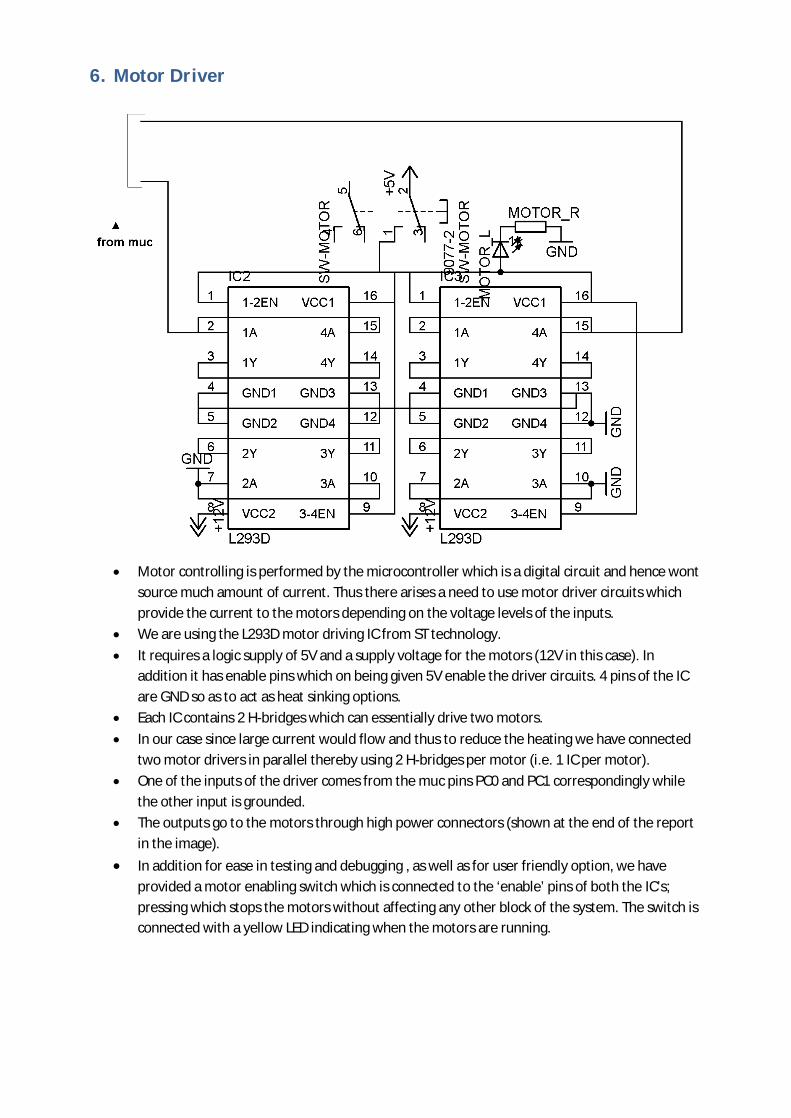
Motor controlling is performed by the microcontroller which is a digital circuit and hence wont
source much amount of current. Thus there arises a need to use motor driver circuits which provide the current to the motors depending on the voltage levels of the inputs.
We are using the L293D motor driving IC from ST technology.
It requires a logic supply of 5V and a supply voltage for the motors (12V in this case). In addition it has enable pins which on being given 5V enable the driver circuits. 4 pins of the IC are GND so as to act as heat sinking options.
Each IC contains 2 H-bridges which can essentially drive two motors.
In our case since large current would flow and thus to reduce the heating we have connected two motor drivers in parallel thereby using 2 H-bridges per motor (i.e. 1 IC per motor).
One of the inputs of the driver comes from the muc pins PC0 and PC1 correspondingly while the other input is grounded.
The outputs go to the motors through high power connectors (shown at the end of the report in the image).
In addition for ease in testing and debugging , as well as for user friendly option, we have provided a motor enabling switch which is connected to the ‘enable’ pins of both the IC’s; pressing which stops the motors without affecting any other block of the system. The switch is connected with a yellow LED indicating when the motors are running.
7. LCD
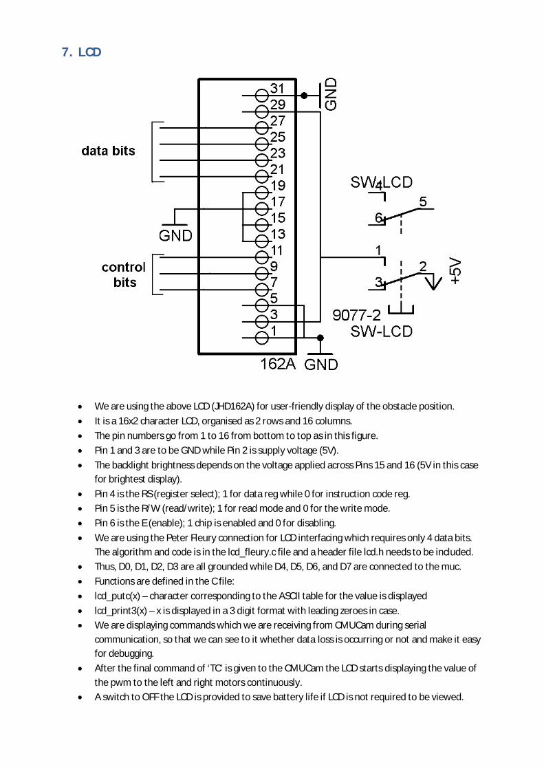
We are using the above LCD (JHD162A) for user-friendly display of the obstacle position.
It is a 16x2 character LCD, organised as 2 rows and 16 columns.
The pin numbers go from 1 to 16 from bottom to top as in this figure.
Pin 1 and 3 are to be GND while Pin 2 is supply voltage (5V).
The backlight brightness depends on the voltage applied across Pins 15 and 16 (5V in this case for brightest display).
Pin 4 is the RS (register select); 1 for data reg while 0 for instruction code reg.
Pin 5 is the R/W (read/write); 1 for read mode and 0 for the write mode.
Pin 6 is the E (enable); 1 chip is enabled and 0 for disabling.
We are using the Peter Fleury connection for LCD interfacing which requires only 4 data bits. The algorithm and code is in the lcd_fleury.c file and a header file lcd.h needs to be included.
Thus, D0, D1, D2, D3 are all grounded while D4, D5, D6, and D7 are connected to the muc.
Functions are defined in the C file:
lcd_putc(x) – character corresponding to the ASCII table for the value is displayed
lcd_print3(x) – x is displayed in a 3 digit format with leading zeroes in case.
We are displaying commands which we are receiving from CMUCam during serial communication, so that we can see to it whether data loss is occurring or not and make it easy for debugging.
After the final command of ‘TC’ is given to the CMUCam the LCD starts displaying the value of the pwm to the left and right motors continuously.
A switch to OFF the LCD is provided to save battery life if LCD is not required to be viewed.
8. LED Torch
While the CMUCam is capturing images, the RGB values obtained from the same object would be different under different lighting conditions and would result in malfunctioning.
Thus if the camera’s field of view is lighted with a constant light source thereby causing the ambiance lighting to not affect the RGB values much and there won’t be a problem of re-calibrating the device each time a new lighting condition is encountered.
For this constant light source we have used what is called a ‘LED Torch’. The torch consists of 8 white LED’s 5mm (larger than 5mm would be better) connected to 5V through resistors.
The supply to this comes through the same switch that connects to the cam so that both are switched ON/OFF simultaneously.
9. Testing Procedure
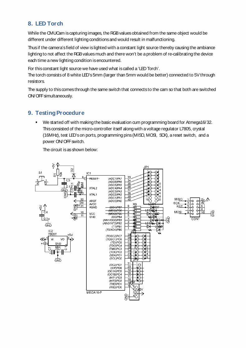
We started off with making the basic evaluation cum programming board for Atmega16/32. This consisted of the micro-controller itself along with a voltage regulator L7805, crystal (16MHz), test LED’s on ports, programming pins (MISO, MOSI, SCK), a reset switch, and a power ON/OFF switch.
The circuit is as shown below:
Using this Board, we started testing for simple codes.
Code 1: testing the ports of the micro-controller. Code 2: blinking of LED’s on the particular port using delay. Code 3: using Timer0, Timer1 for making LED’s flicker at a given frequency. Code 4: testing of ADC with Timer0 as the input and output on LED’s. Code 5: USART receive and transmission using RS232 from PC to micro-controller.
USART communication of PC and microcontroller:
As an add-on to the above circuit we were required to make a RS232 board for serial port interfacing between PC and the microcontroller. This circuit was for matching of the voltage levels of the serial ports. For testing the circuit we connected the serial port of the PC and shorted the transmitter and receiver pins of the port. Thus whatever data would be sent from the PC using a key board would also be received by the PC at the same time. Hence the serial port was in functioning condition. Now we did the same thing with the outputs of the RS232 circuit and the results were positive.
Thereafter we started sending bytes of data from the microcontroller using RS232. The data sent from the microcontroller was observed on the PC using ‘Hyper Term’. Baud rate used was 115.2kbps and 8-bit transmission.
After achieving success in transmission we went on to check the receiving part. Now data was typed using the keyboard onto the hyper term which would then send the data through the RS232 to the microcontroller at a baud rate of 115.2kbps
Then we tested receive and transmission of the microcontroller by receiving information from the PC and then modifying it slightly and sending it back to the PC.
int main(void) { uint8_t i = 0; init_UART(8); // baudrate = 115.2kbps for 16MHz for(;;) // Forever { i = ReceiveByte(); i = i+1; TransmitByte(i); } }
CMU Cam testing with PC:
Again using the RS232 circuit the CMUCam was interfaced with the PC. As per the manual of the cam, on switching ON the device it sends the following command:
CMUcam2 v1.0 c6 :
After this we started testing some random commands like ‘gv’, which gets the version of the cam; ‘ST’ which sets tracking colour; ‘GT’ which recalls the racking colours set and outputs them; ‘TC’ which tracks the colour range specified in the image captured.

Command: gv \r Output: ACK
CMUcam2 v1.0 c6 :
Command: ST 200 0 0 250 20 20 \\ ST Rmin Rmax Gmin Gmax Bmin Bmax \r Output: ACK : Command: GT \r Output: ACK 200 0 0 250 20 20 : Command: TC \r Output: ACK
T 6 55 2 40 12 60 10 70 T 6 55 2 41 12 61 11 70 ....................................
Using the GUI of the Cam: The Cam comes with a graphical user interface that helps us to view the image being captured by the cam and do other thing like tracking a colour and observing the histogram of intensities of red, green and blue. We used this to observe the RGB values of a particular part of the image. (i.e. the white strip in our case)
LCD interfacing of the microcontroller: The LCD JHD 162A was used to display the data being received from the cam and other flags. It was interfaced using the Peter Fleury algorithm. LCD was tested by displaying various types of characters and messages.

10. Conclusion and Further Improvement
Our final goal was to make line follower which can follow any line smoothly. What we ahve achieved is a machine that can follow any coloured line if we specify its appropriate colour range (i.e. the RGB values beforehand). As far as smoothness is concerned, it is not very smooth. Further development in algorithm is required to be done to increase the smoothness that is improvement in the control. Sometimes the machine leaves the line if disturbance is very high, especially when disturbance is towards left of the machine. All this can be achieved by improvising the algorithm used to drive the machine.
11. User Manual
Contents in the package 1x Main board 1x CMUCam 1x LCD Display 2x Power Module 2x Motor Driver Cables for connection
Refer to any of the sections or the datasheets for further information
Description of components
The main board has a 6 pin religmate connector which is used for programming the muc and should not be used by the user at any other point of time.
The board also has one 4 pin connector which is used to connect the CMUCam and the muc.
There are two 2-pin religmate connectors which are used as connections to the supply of the CMUCam board and LED Torch board.
There are 3 power-amp connectors, of which one is used for main power supply and the other two are for the motors.
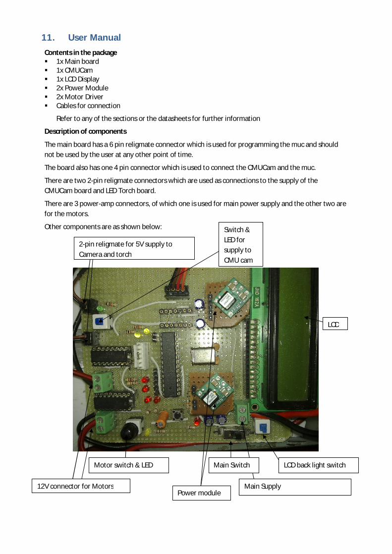
Other components are as shown below:
2-pin religmate for 5V supply to Camera and torch
12V connector for Motors Main Supply Power module
LCD
Switch & LED for supply to CMU cam
Motor switch & LED Main Switch LCD back light switch