Embed Size (px)
Citation preview
super
cylinder
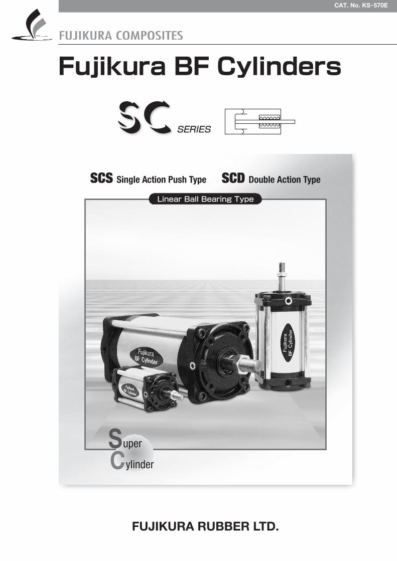
Linear Ball Bearing Type
CAT. No. KS-570E
SCS Single Action Push Type SCD Double Action Type
SC SERIES
FUJIKURA RUBBER LTD.
1
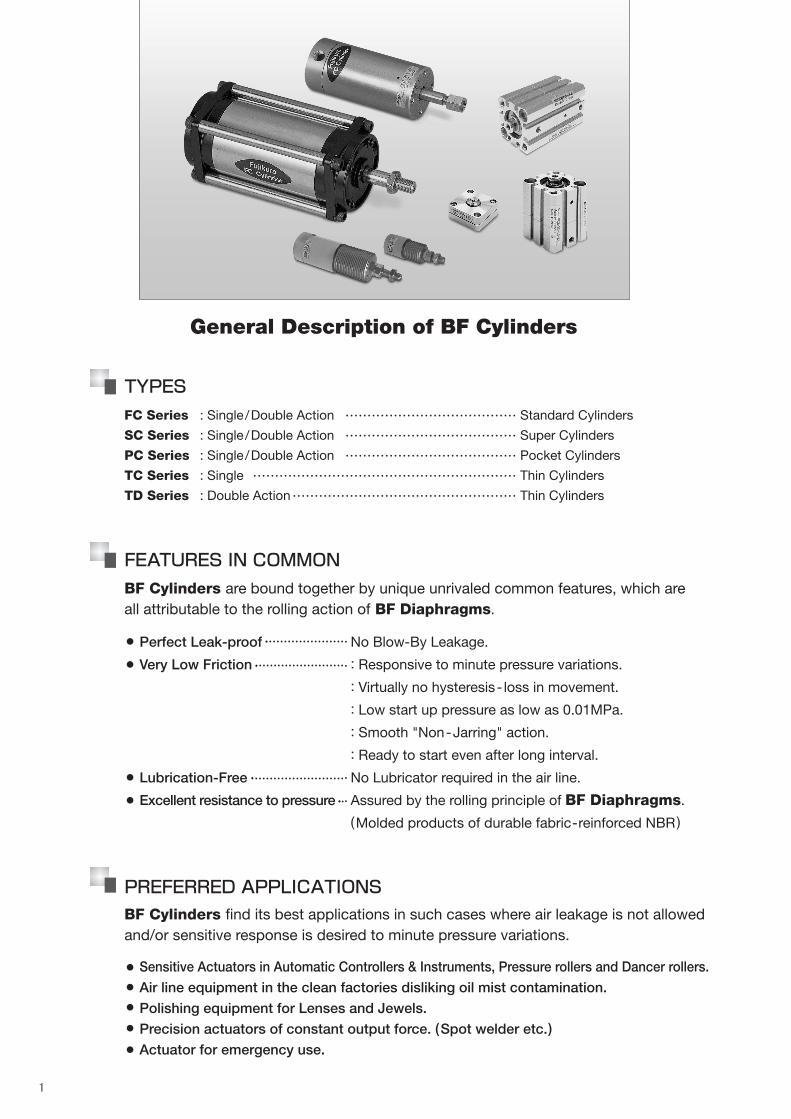
General Description of BF Cylinders
TYPES
FC Series : Single/Double Action ………………………………… Standard Cylinders
SC Series : Single/Double Action ………………………………… Super Cylinders
PC Series : Single/Double Action ………………………………… Pocket Cylinders
TC Series : Single …………………………………………………… Thin Cylinders
TD Series : Double Action…………………………………………… Thin Cylinders
FEATURES IN COMMON
BF Cylinders are bound together by unique unrivaled common features, which areall attributable to the rolling action of BF Diaphragms.
Perfect Leak-proof No Blow-By Leakage.
Very Low Friction : Responsive to minute pressure variations.
: Virtually no hysteresis- loss in movement.
: Low start up pressure as low as 0.01MPa.
: Smooth "Non-Jarring" action.
: Ready to start even after long interval.
Lubrication-Free No Lubricator required in the air line.
Excellent resistance to pressure Assured by the rolling principle of BF Diaphragms.
(Molded products of durable fabric-reinforced NBR)
●
●
●
●
PREFERRED APPLICATIONS
Sensitive Actuators in Automatic Controllers & Instruments, Pressure rollers and Dancer rollers.
Air line equipment in the clean factories disliking oil mist contamination.
Polishing equipment for Lenses and Jewels.
Precision actuators of constant output force. (Spot welder etc.)
Actuator for emergency use.
●
●
●
BF Cylinders find its best applications in such cases where air leakage is not allowedand/or sensitive response is desired to minute pressure variations.
●
●
2
series
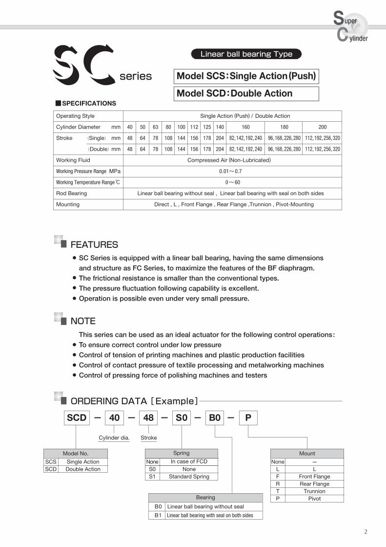
Operating Style Single Action (Push) / Double Action
Cylinder Diameter mm 40 50 63 80 100 112 125 140 160 180 200
Stroke (Single) mm 48 64 78 108 144 156 178 204 82,142,192,240 96,168,226,280 112,192,256,320
(Double)mm 48 64 78 108 144 156 178 204 82,142,192,240 96,168,226,280 112,192,256,320
Working Fluid Compressed Air (Non-Lubricated)
Working Pressure Range MPa 0.01~0.7
Working Temperature Range℃ 0~60
Rod Bearing Linear ball bearing without seal , Linear ball bearing with seal on both sides
Mounting Direct , L , Front Flange , Rear Flange ,Trunnion , Pivot-Mounting
■SPECIFICATIONS
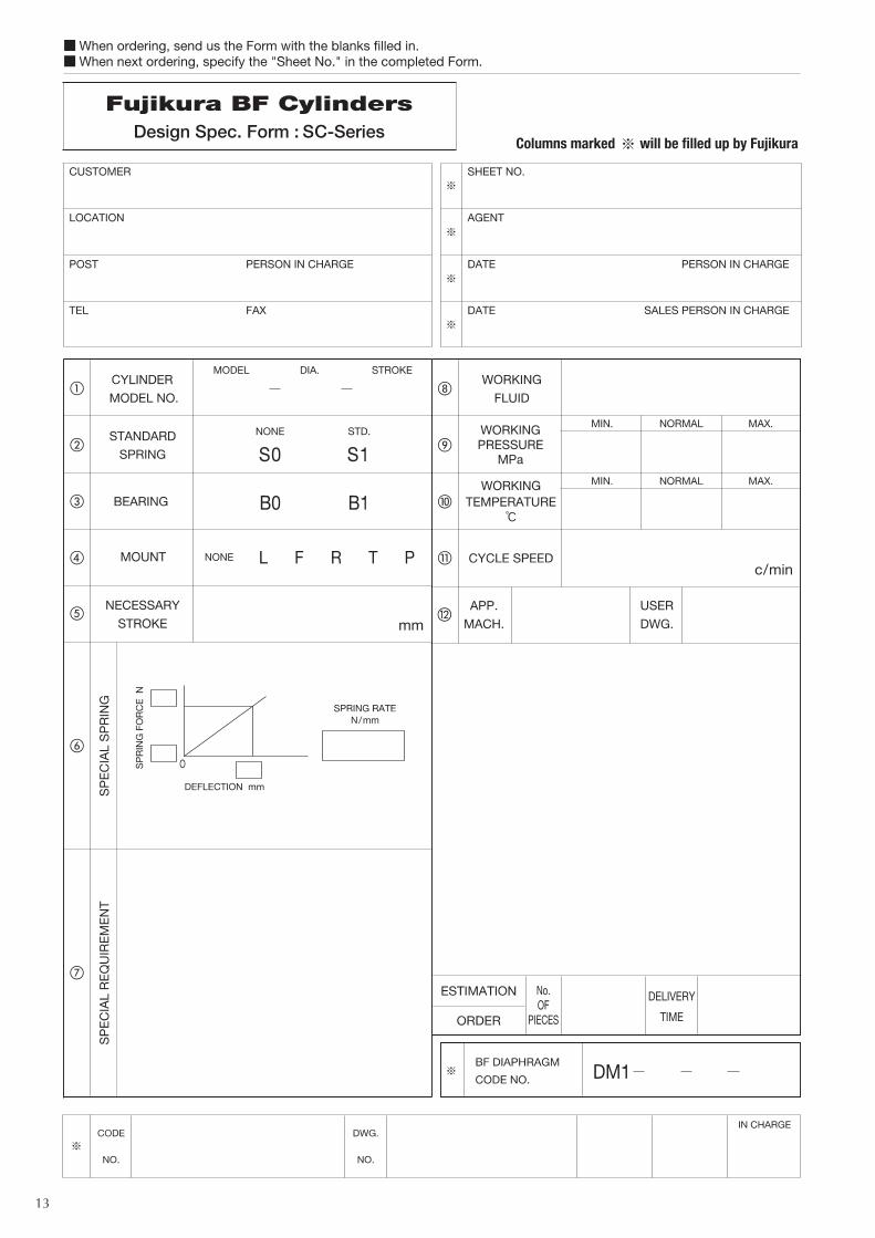
Model SCS:Single Action(Push)
Model SCD:Double Action
SCD 40 48 S0 B0 P
Cylinder dia. Stroke
Bearing
B0 Linear ball bearing without seal
B1 Linear ball bearing with seal on both sides
SC Linear ball bearing Type
FEATURESSC Series is equipped with a linear ball bearing, having the same dimensions
and structure as FC Series, to maximize the features of the BF diaphragm.
The frictional resistance is smaller than the conventional types.
The pressure fluctuation following capability is excellent.
Operation is possible even under very small pressure.
●
●
●
●
NOTE
This series can be used as an ideal actuator for the following control operations:
To ensure correct control under low pressure
Control of tension of printing machines and plastic production facilities
Control of contact pressure of textile processing and metalworking machines
Control of pressing force of polishing machines and testers
●
●
●
●
ORDERING DATA [Example]
sc
uper
ylinder
Mount
None ---L LF Front FlangeR Rear FlangeT TrunnionP Pivot
Spring
S0 NoneS1 Standard Spring
Model No.
SCS Single ActionSCD Double Action
None In case of FCD
3
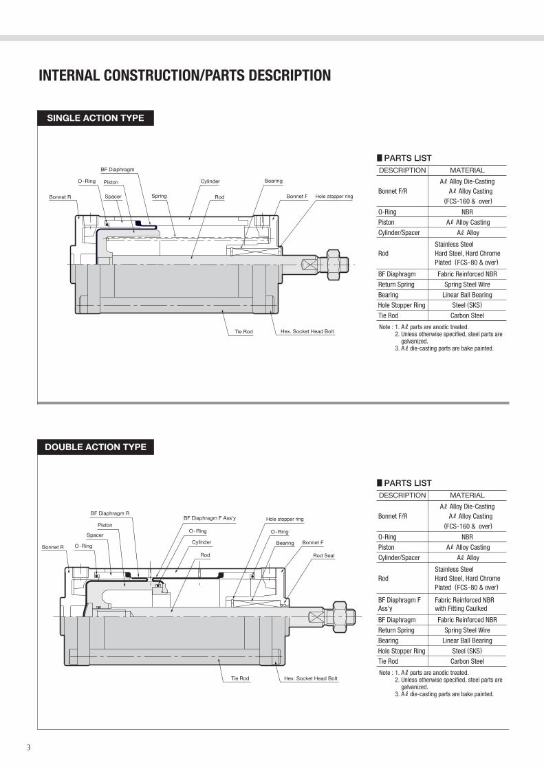
INTERNAL CONSTRUCTION/PARTS DESCRIPTION
SINGLE ACTION TYPE
DOUBLE ACTION TYPE
Note : 1. A parts are anodic treated.2. Unless otherwise specified, steel parts are
galvanized.3. A die-casting parts are bake painted.
■PARTS LISTDESCRIPTION MATERIAL
Piston
O-Ring
A Alloy Casting
NBR
Cylinder/Spacer A Alloy
BF Diaphragm Fabric Reinforced NBR
Return Spring Spring Steel Wire
Bearing Linear Ball Bearing
Tie Rod Carbon Steel
Bonnet F/RA Alloy Die-Casting
A Alloy Casting(FCS-160 & over)
RodStainless Steel Hard Steel, Hard ChromePlated (FCS-80 & over)
BF Diaphragm F Ass'y
Fabric Reinforced NBR with Fitting Caulked
Note : 1. A parts are anodic treated.2. Unless otherwise specified, steel parts are
galvanized.3. A die-casting parts are bake painted.
■PARTS LISTDESCRIPTION MATERIAL
Piston
O-Ring
A Alloy Casting
NBR
Cylinder/Spacer A Alloy
BF Diaphragm Fabric Reinforced NBR
Return Spring Spring Steel Wire
Bearing Linear Ball Bearing
Tie Rod Carbon Steel
Bonnet F/RA Alloy Die-Casting
A Alloy Casting(FCS-160 & over)
RodStainless Steel Hard Steel, Hard ChromePlated (FCS-80 & over)
Hole Stopper Ring Steel (SKS)
Hole Stopper Ring Steel (SKS)
4
sc
uper
ylinder
SCD-40~ 200
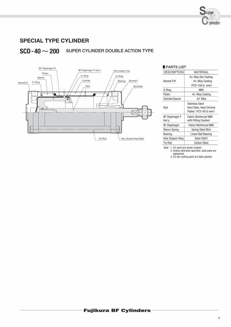
SPECIAL TYPE CYLINDER
SUPER CYLINDER DOUBLE ACTION TYPE
Fujikura BF Cylinders
BF Diaphragm F Ass'y
Fabric Reinforced NBR with Fitting Caulked
Note : 1. A parts are anodic treated.2. Unless otherwise specified, steel parts are
galvanized.3. A die-casting parts are bake painted.
■PARTS LISTDESCRIPTION MATERIAL
Piston
O-Ring
A Alloy Casting
NBR
Cylinder/Spacer A Alloy
BF Diaphragm Fabric Reinforced NBR
Return Spring Spring Steel Wire
Bearing Linear Ball Bearing
Tie Rod Carbon Steel
Bonnet F/RA Alloy Die-Casting
A Alloy Casting(FCS-160 & over)
RodStainless Steel Hard Steel, Hard ChromePlated (FCS-80 & over)
Hole Stopper Ring Steel (SKS)

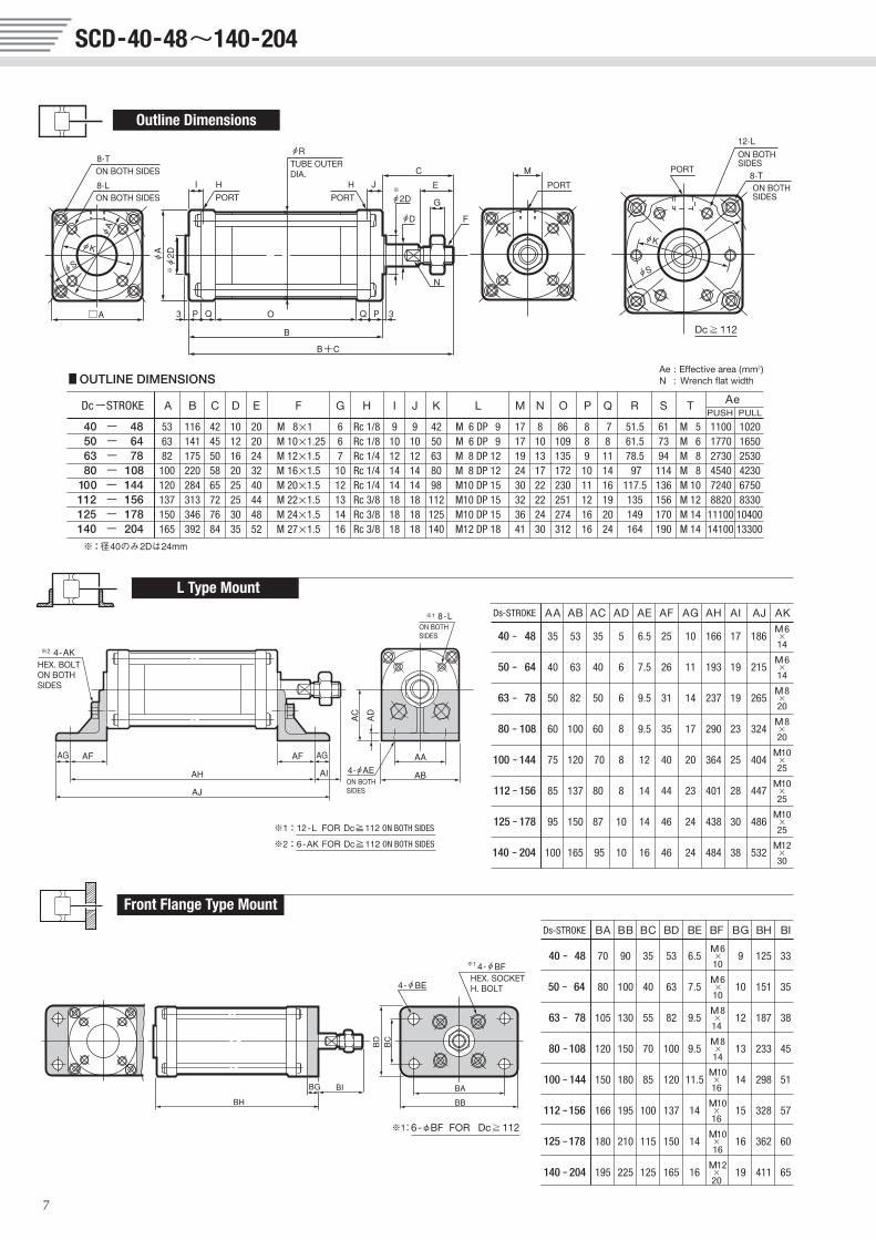
SCS-40-48~140-204
5
O
■OUTLINE DIMENSIONS
Dc-STROKE A B C D E F G H I J K L M N O P Q R S T AeSPRING FORCE
F0 F1
40 - 48 53 105 42 10 20 M 8×1 6 Rc 1/8 9 - 42 M 6DP 9 17 8 75 8 7 51.5 61 M 5 1100 7.8 19.650 - 64 63 130 45 12 20 M 10×1.25 6 Rc 1/8 10 - 50 M 6DP 9 17 10 98 8 8 61.5 73 M 6 1770 14.7 29.463 - 78 82 160 50 16 24 M 12×1.5 7 Rc 1/4 12 - 63 M 8DP 12 19 13 120 9 11 78.5 94 M 8 2730 23.5 4780 - 108 100 205 58 20 32 M 16×1.5 10 Rc 1/4 14 - 80 M 8DP 12 24 17 157 10 14 97 114 M 8 4540 39.2 78.4
100 - 144 120 268 65 25 40 M 20×1.5 12 Rc 1/4 14 - 98 M10DP 15 30 22 214 11 16 117.5 136 M 10 7240 61.7 127.4112 - 156 137 290 72 25 44 M 22×1.5 13 Rc 3/8 18 - 112 M10DP 15 32 22 228 12 19 135 156 M 12 8820 76.4 158.8125 - 178 150 322 76 30 48 M 24×1.5 14 Rc 3/8 18 - 125 M10DP 15 36 24 249 16 20 149 170 M 14 11100 95.1 198140 - 204 165 370 84 35 52 M 27×1.5 16 Rc 3/8 18 - 140 M12DP 18 41 30 290 16 24 164 190 M 14 14100 119.6 254.8
Ds-STROKE AA AB AC AD AE AF AG AH AI AJ AKM6
40 -- 48 35 53 35 5 6.5 25 10 155 17 175 ×14
M650 -- 64 40 63 40 6 7.5 26 11 182 19 204 ×
14
M863 -- 78 50 82 50 6 9.5 31 14 222 19 250 ×
20
M880 -- 108 60 100 60 8 9.5 35 17 275 23 309 ×
20
M10100 -- 144 75 120 70 8 12 40 20 348 25 388 ×
25
M10112 -- 156 85 137 80 8 14 44 23 378 28 424 ×
25
M10125 -- 178 95 150 87 10 14 46 24 415 30 463 ×
25
M12140 -- 204 100 165 95 10 16 46 24 462 38 510 ×
30
Ds-STROKE BA BB BC BD BE BF BG BH BI
M640 -- 48 70 90 35 53 6.5 × 9 114 33
10
M650 -- 64 80 100 40 63 7.5 × 10 140 35
10
M863 -- 78 105 130 55 82 9.5 × 12 172 38
14
M880 --108 120 150 70 100 9.5 × 13 218 45
14
M10100 -- 144 150 180 85 120 11.5 × 14 282 51
16
M10112 --156 166 195 100 137 14 × 15 305 57
16
M10125 --178 180 210 115 150 14 × 16 338 60
16
M12140 -- 204 195 225 125 165 16 × 19 389 65
20
F0/F1 : Spring force at zero/full stroke (N)Ae : Effective area (mm2)N : Wrench flat width
※:径40のみ2Dは24mm
L Type Mount
Front Flange Type Mount
Outline Dimensions

6
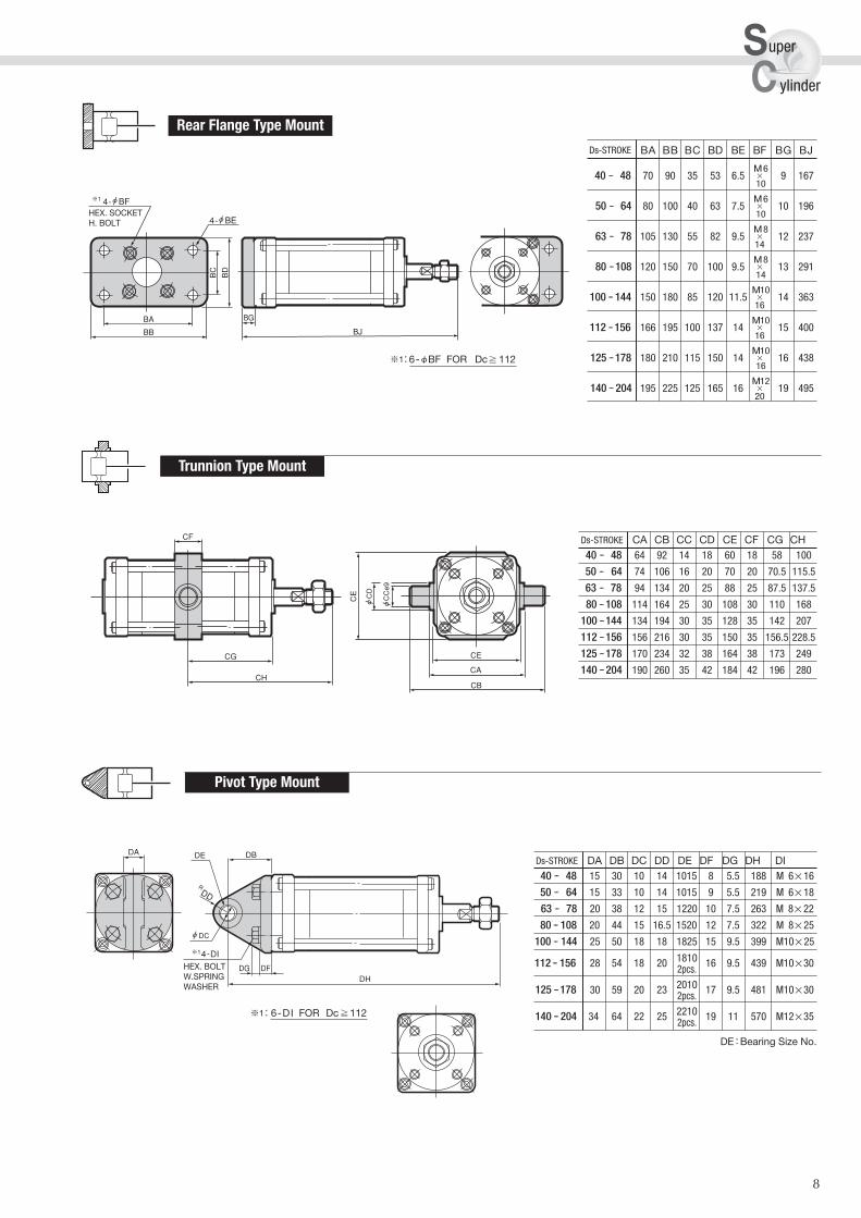
Ds-STROKE CA CB CC CD CE CF CG CH40 -- 48 64 92 14 18 60 18 52.5 94.5
50 -- 64 74 106 16 20 70 20 65 110
63 -- 78 94 134 20 25 88 25 80 130
80 --108 114 164 25 30 108 30 102.5 160.5
100 --144 134 194 30 35 128 35 134 199
112 --156 156 216 30 35 150 35 145 217
125 --178 170 234 32 38 164 38 161 237
140 --204 190 260 35 42 184 42 185 269
Ds-STROKE DA DB DC DD DE DF DG DH DI40 -- 48 15 30 10 14 1015 8 5.5 177 M 6×16
50 -- 64 15 33 10 14 1015 9 5.5 208 M 6×18
63 -- 78 20 38 12 15 1220 10 7.5 248 M 8×22
80 -- 108 20 44 15 16.5 1520 12 7.5 307 M 8×25
100 -- 144 25 50 18 18 1825 15 9.5 383 M10×25
112 -- 156 28 54 18 20 1810 16 9.5 416 M10×302pcs.
125 --178 30 59 20 23 2010 17 9.5 457 M10×302pcs.
140 -- 204 34 64 22 25 2210 19 11 518 M12×352pcs.
DE : Bearing Size No.
sc
uper
ylinder
Ds-STROKE BA BB BC BD BE BF BG BJ
M640 -- 48 70 90 35 53 6.5 × 9 156
10
M650 -- 64 80 100 40 63 7.5 × 10 185
10
M863 -- 78 105 130 55 82 9.5 × 12 222
14
M880 --108 120 150 70 100 9.5 × 13 276
14
M10100 -- 144 150 180 85 120 11.5 × 14 347
16
M10112 --156 166 195 100 137 14 × 15 377
16
M10125 --178 180 210 115 150 14 × 16 414
16
M12140 -- 204 195 225 125 165 16 × 19 473
20
Rear Flange Type Mount
Trunnion Type Mount
Pivot Type Mount
SCD-40-48~140-204
7
O
Ds-STROKE AA AB AC AD AE AF AG AH AI AJ AKM6
40 -- 48 35 53 35 5 6.5 25 10 166 17 186 ×14
M650 -- 64 40 63 40 6 7.5 26 11 193 19 215 ×
14
M863 -- 78 50 82 50 6 9.5 31 14 237 19 265 ×
20
M880 -- 108 60 100 60 8 9.5 35 17 290 23 324 ×
20
M10100 -- 144 75 120 70 8 12 40 20 364 25 404 ×
25
M10112 -- 156 85 137 80 8 14 44 23 401 28 447 ×
25
M10125 -- 178 95 150 87 10 14 46 24 438 30 486 ×
25
M12140 -- 204 100 165 95 10 16 46 24 484 38 532 ×
30
Ds-STROKE BA BB BC BD BE BF BG BH BI
M640 -- 48 70 90 35 53 6.5 × 9 125 33
10
M650 -- 64 80 100 40 63 7.5 × 10 151 35
10
M863 -- 78 105 130 55 82 9.5 × 12 187 38
14
M880 --108 120 150 70 100 9.5 × 13 233 45
14
M10100 -- 144 150 180 85 120 11.5 × 14 298 51
16
M10112 --156 166 195 100 137 14 × 15 328 57
16
M10125 --178 180 210 115 150 14 × 16 362 60
16
M12140 -- 204 195 225 125 165 16 × 19 411 65
20
■OUTLINE DIMENSIONS
Dc-STROKE A B C D E F G H I J K L M N O P Q R S T AePUSH PULL
40 - 48 53 116 42 10 20 M 8×1 6 Rc 1/8 9 9 42 M 6 DP 9 17 8 86 8 7 51.5 61 M 5 1100 102050 - 64 63 141 45 12 20 M 10×1.25 6 Rc 1/8 10 10 50 M 6 DP 9 17 10 109 8 8 61.5 73 M 6 1770 165063 - 78 82 175 50 16 24 M 12×1.5 7 Rc 1/4 12 12 63 M 8 DP 12 19 13 135 9 11 78.5 94 M 8 2730 253080 - 108 100 220 58 20 32 M 16×1.5 10 Rc 1/4 14 14 80 M 8 DP 12 24 17 172 10 14 97 114 M 8 4540 4230
100 - 144 120 284 65 25 40 M 20×1.5 12 Rc 1/4 14 14 98 M10 DP 15 30 22 230 11 16 117.5 136 M 10 7240 6750112 - 156 137 313 72 25 44 M 22×1.5 13 Rc 3/8 18 18 112 M10 DP 15 32 22 251 12 19 135 156 M 12 8820 8330125 - 178 150 346 76 30 48 M 24×1.5 14 Rc 3/8 18 18 125 M10 DP 15 36 24 274 16 20 149 170 M 14 11100 10400140 - 204 165 392 84 35 52 M 27×1.5 16 Rc 3/8 18 18 140 M12 DP 18 41 30 312 16 24 164 190 M 14 14100 13300
Ae : Effective area (mm2)N : Wrench flat width
※:径40のみ2Dは24mm
L Type Mount
Front Flange Type Mount
Outline Dimensions
8
Ds-STROKE CA CB CC CD CE CF CG CH40 -- 48 64 92 14 18 60 18 58 100
50 -- 64 74 106 16 20 70 20 70.5 115.5
63 -- 78 94 134 20 25 88 25 87.5 137.5
80 --108 114 164 25 30 108 30 110 168
100 --144 134 194 30 35 128 35 142 207
112 --156 156 216 30 35 150 35 156.5 228.5
125 --178 170 234 32 38 164 38 173 249
140 --204 190 260 35 42 184 42 196 280
Ds-STROKE DA DB DC DD DE DF DG DH DI40 -- 48 15 30 10 14 1015 8 5.5 188 M 6×16
50 -- 64 15 33 10 14 1015 9 5.5 219 M 6×18
63 -- 78 20 38 12 15 1220 10 7.5 263 M 8×22
80 -- 108 20 44 15 16.5 1520 12 7.5 322 M 8×25
100 -- 144 25 50 18 18 1825 15 9.5 399 M10×25
112 -- 156 28 54 18 20 1810 16 9.5 439 M10×302pcs.
125 --178 30 59 20 23 2010 17 9.5 481 M10×302pcs.
140 -- 204 34 64 22 25 2210 19 11 570 M12×352pcs.
DE : Bearing Size No.
sc
uper
ylinder
Ds-STROKE BA BB BC BD BE BF BG BJ
M640 -- 48 70 90 35 53 6.5 × 9 167
10
M650 -- 64 80 100 40 63 7.5 × 10 196
10
M863 -- 78 105 130 55 82 9.5 × 12 237
14
M880 --108 120 150 70 100 9.5 × 13 291
14
M10100 -- 144 150 180 85 120 11.5 × 14 363
16
M10112 --156 166 195 100 137 14 × 15 400
16
M10125 --178 180 210 115 150 14 × 16 438
16
M12140 -- 204 195 225 125 165 16 × 19 495
20
Rear Flange Type Mount
Trunnion Type Mount
Pivot Type Mount
Dc-STROKE AA AB AC AD AE AF AG AH AI AJ AK
160 - 82 282 334 M12142
115 185 105 13 18 49 26372
19424
×192 449 501 30240 523 575
180 - 96 331 387M14168
130 205 115 14 18 52 28425
24481
×226 514 570 35280 597 653
200 - 112 348 404 M16192
140 225 125 14 18 52 28468
40524
×256 566 622 35 320 664 720
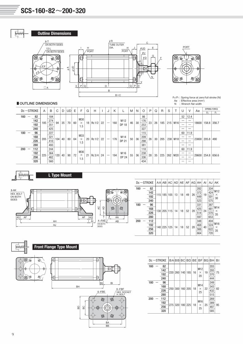
SCS-160-82~200-320
9
■OUTLINE DIMENSIONS
Dc-STROKE A B C D UD E F G H I J K L M N O P Q R S T U V AeSPRING FORCE
F0 F1
160 - 82 184M30
86 52 12.4 142
185274
94 35 70 60 × 18 Rc 1/2 22 - 160M 12
46 30176
23 26 185 215 M16- -
18600 158.8 356.7192 351 1.5 DP 18 253 - -240 425 327 - -
180 - 96 227M33
115 60 11.9 168
205321
104 40 80 64 × 20 Rc 1/2 22 - 176M 14
50 36 209
26 30 205 238 M18- -
23800 205.8 490226 410 1.5 DP 21 298 - -280 493 381 - -
200 - 112 244M36
118 60 11.9 192
225364
120 40 90 72 × 21 Rc 3/4 24 - 194M 16
55 36238
28 35 225 262 M20- -
29600 254.8 656.6256 462 1.5 DP 24 336 - -320 560 434 - -
Dc-STROKE BA BB BC BD BE BF BG BH BI
160 - 82M12
203 142
220 260 140 185 16 × 19293
75192 20 370 240 444
180 - 96M14
249 168
250 300 160 205 18 × 22343
82226 25 432 280 515
200 - 112M16
269 192
275 320 180 225 18 × 25389
95256 25 487 320 585
F0/F1 : Spring force at zero/full stroke (N)Ae : Effective area (mm2)N : Wrench flat width
L Type Mount
Front Flange Type Mount
Outline Dimensions
10
DG DF
DE : Bearing Size No.
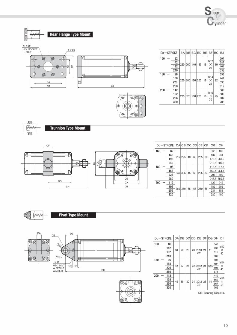
Dc-STROKE BA BB BC BD BE BF BG BJ
160 - 82M12
297142
220 260 140 185 16 × 19387
192 20 464240 538
180 - 96M14
353168
250 300 160 205 18 × 22447
226 25 536280 619
200 - 112M16
389192
275 320 180 225 18 × 25509
256 30 607 320 705
Dc-STROKE CA CB CC CD CE CF CG CH
160 - 82 92 186142
215 295 40 60 205 60137 231
192 175.5 269.5240 212.5 306.5
180 - 96 113.5 217.5 168
235 325 45 63 225 63160.5 264.5
226 205 309280 246.5 350.5
200 - 112 122 242192
260 350 45 65 250 65182 302
256 231 351 320 280 400
Dc-STROKE DA DB DC DD DE DF DG DH DI
160 - 82 348 M12142
38 70 25 28 2510 21 11438
×192 2ケ 515 40240 589
180 - 96 408 M14168
42 77 28 32 2812 24 12.5502
×226 2ケ 591 45280 674
200 - 112 449 M16192
45 85 30 34 3012 26 14569
×256 2ケ 667 50320 765
sc
uper
ylinder
Rear Flange Type Mount
Trunnion Type Mount
Pivot Type Mount
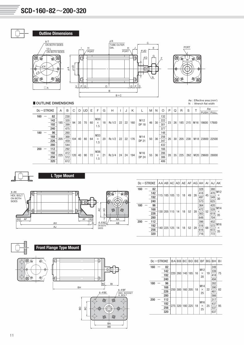
Dc-STROKE AA AB AC AD AE AF AG AH AI AJ AK
160 - 82 328 380 M12142
115 185 105 13 18 49 26418
45470
×192 497 549 30240 573 625
180 - 96 364 420M14168
130 205 115 14 18 52 28472
52528
×226 563 619 35280 648 704
200 - 112 396 452 M16192
140 225 125 14 18 52 28516
68572
×256 616 672 35 320 716 772
SCD-160-82~200-320
11
■OUTLINE DIMENSIONS
Dc-STROKE A B C D UD E F G H I J K L M N O P Q R S T AePUSH PULL
160 - 82 230M30
132142
185320
94 35 70 60 × 18 Rc 1/2 22 22 160M 12
46 30222
23 26 185 215 M16 18600 17600192 399 1.5 DP 18 301240 475 377
180 - 96 260M33
148168
205368
104 40 80 64 × 20 Rc 1/2 22 22 176M 14
50 36 256
26 30 205 238 M18 23800 22500226 459 1.5 DP 21 347280 544 432
200 - 112 292M36
166192
225412
120 40 90 72 × 21 Rc 3/4 24 24 194M 16
55 36286
28 35 225 262 M20 29600 28000256 512 1.5 DP 24 386320 612 486
Dc-STROKE BA BB BC BD BE BF BG BH BI
160 - 82M12
249 142
220 260 140 185 16 × 19339
75192 20 418 240 494
180 - 96M14
282 168
250 300 160 205 18 × 22390
82226 25 481 280 566
200 - 112M16
317 192
275 320 180 225 18 × 25437
95256 25 537 320 637
Ae : Effective area (mm2)N : Wrench flat width
L Type Mount
Front Flange Type Mount
Outline Dimensions
12
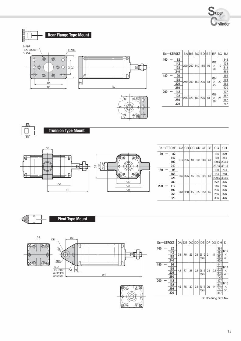
DE : Bearing Size No.
Dc-STROKE BA BB BC BD BE BF BG BJ
160 - 82M12
343142
220 260 140 185 16 × 19433
192 20 512240 588
180 - 96M14
386 168
250 300 160 205 18 × 22494
226 25 585280 670
200 - 112M16
437192
275 320 180 225 18 × 25557
256 30 657 320 757
Dc-STROKE CA CB CC CD CE CF CG CH
160 - 82 115 209142
215 295 40 60 205 60160 254
192 199.5 293.5240 237.5 331.5
180 - 96 130 234 168
235 325 45 63 225 63184 288
226 229.5 333.5280 272 376
200 - 112 146 266192
260 350 45 65 250 65206 326
256 256 376 320 306 426
Dc-STROKE DA DB DC DD DE DF DG DH DI
160 - 82 394 M12142
38 70 25 28 2510 21 11484
×192 2pcs. 563 40240 639
180 - 96 441 M14168
42 77 28 32 2812 24 12.5549
×226 2pcs. 640 45280 725
200 - 112 497 M16192
45 85 30 34 3012 26 14617
×256 2pcs. 717 50320 817
sc
uper
ylinder
DG DF
Rear Flange Type Mount
Trunnion Type Mount
Pivot Type Mount
13
14
Fujikura BF Cylinders
MEMO
Printed in Japan©SBC
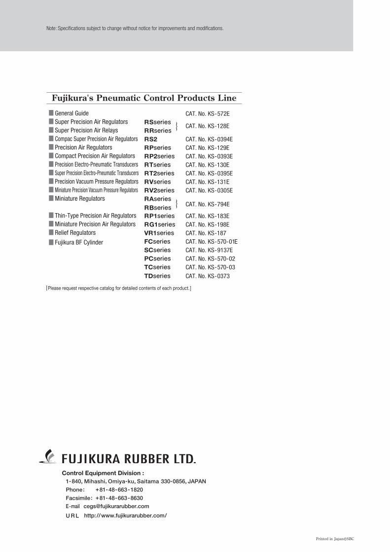
Note :Specifications subject to change without notice for improvements and modifications.
1-840, Mihashi, Omiya-ku, Saitama 330-0856, JAPAN
Phone: +81-48-663-1820
Facsimile : +81-48-663-8630E-mail [email protected]
U R L http://www.fujikurarubber.com/
Control Equipment Division :
Fujikura's Pneumatic Control Products Line
[Please request respective catalog for detailed contents of each product. ]
■ General Guide CAT. No. KS-572E■ Super Precision Air Regulators RSseries■ Super Precision Air Relays RRseries
CAT. No. KS-128E
■ Compac Super Precision Air Regulators RS2 CAT. No. KS-0394E■ Precision Air Regulators RPseries CAT. No. KS-129E■ Compact Precision Air Regulators RP2series CAT. No. KS-0393E■ Precision Electro-Pneumatic Transducers RTseries CAT. No. KS-130E■ Super Precision Electro-Pneumatic Transducers RT2series CAT. No. KS-0395E■ Precision Vacuum Pressure Regulators RVseries CAT. No. KS-131E■ Miniature Precision Vacuum Pressure Regulators RV2series CAT. No. KS-0305E■Miniature Regulators RAseries
RBseries CAT. No. KS-794E
■ Thin-Type Precision Air Regulators RP1series CAT. No. KS-183E■Miniature Precision Air Regulators RG1series CAT. No. KS-198E■ Relief Regulators VR1series CAT. No. KS-187
■ Fujikura BF Cylinder FCseries CAT. No. KS-570-01ESCseries CAT. No. KS-9137EPCseries CAT. No. KS-570-02TCseries CAT. No. KS-570-03
TDseries CAT. No. KS-0373
}
}