Embed Size (px)
Citation preview
International Research Journal of Engineering and Technology (IRJET) e-ISSN: 2395-0056
Volume: 05 Issue: 12 | Dec 2018 www.irjet.net p-ISSN: 2395-0072
© 2018, IRJET | Impact Factor value: 7.211 | ISO 9001:2008 Certified Journal | Page 580
Linear Buckling Analysis of Atlas Torpedo
Pothuraju.V.V.Satyanarayana1, K. Jyothi Rani2, P. Satya Lakshmi3, M. Murali Krishna4
1Assistant Professor, Department of Mechanical Engineering, Avanthi Institute of Engineering and Technology, Makavarapalem, Visakhapatnam, INDIA.
2Post Graduate student, Department of Mechanical Engineering, Visakha Technical Campus, Narava, Visakhapatnam, INDIA.
3Assistant Professor, Department of Mechanical Engineering, Visakha Technical Campus, Narava, Visakhapatnam, INDIA.
4Professor, Department of Mechanical Engineering, Visakha Technical Campus, Narava, Visakhapatnam, INDIA. ---------------------------------------------------------------------***---------------------------------------------------------------------Abstract - In this paper Atlas torpedo is modeled using
finite elements and its static characteristics are analyzed
subject to variations in the design parameters structural
problem. While launching of these torpedoes, the torpedo
experiences the water entry shock. The shell was analyzed
for the shock load. The stresses developed due to the
above shock load were found to be within the acceptable
limit. Hear Buckling is a sudden failure of a structural
member subjected to high compressive stress and it is a
structural instability leading to a failure mode. Buckling
strength of structures depends on many parameters like
supports, linear material, composite or nonlinear material
etc. This project intends to study buckling behavior of
Torpedo which is influenced by Static structural.
The Geometry of the models is carried out in the CATIA V5
R20 Software and is designed in Mechanical Design. The
analysis part is done by using the ANSYS R14.5 & R15.0
Software.
Key Words: Atlas, Buckling, CATIA, ANSYS.
1. INTRODUCTION The torpedo is one of the oldest weapons in the naval
inventory, having been invented over 130 years ago, but at
the same time it remains one of the deadliest anti-ship and
anti-submarine weapon, it is far more lethal to submarines
and surface ship than any other conventional weapon.
torpedo warhead explodes under water, and that
increases its destructive effect. When projectile explodes,
the surrounding air absorbs a part of its force. Homing
torpedoes are a relatively recent development they have
been perfected since the end of World War II. With homing
torpedoes, a destroyer can attack a submerged submarine,
even when its exact position and depth are unknown.
When a structure is subjected to compressive stress,
buckling may occur. Buckling is characterized by a sudden
sideways deflection of a structural member. This may
occur even though the stresses that develop in the
structure are well below those needed to cause failure of
the material of which the structure is composed. As an
applied load is increased on a member, such as a column, it
will ultimately become large enough to cause the member
to become unstable and it is said to have buckled. Further
loading will cause significant and somewhat unpredictable
deformations, possibly leading to complete loss of the
member's load-carrying capacity. If the deformations that
occur after buckling do not cause the complete collapse of
that member, the member will continue to support the
load that caused it to buckle. If the buckled member is part
of a larger assemblage of components such as a building,
any load applied to the buckled part of the structure
beyond that which caused the member to buckle will be
redistributed within the structure.
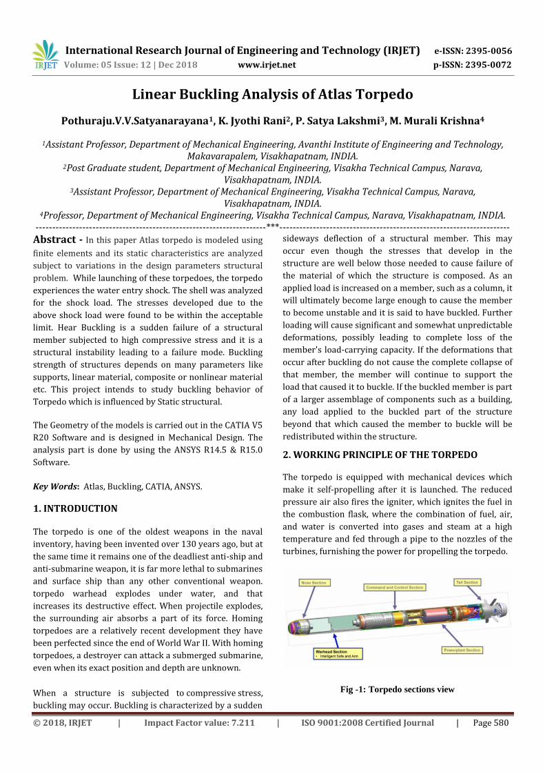
2. WORKING PRINCIPLE OF THE TORPEDO
The torpedo is equipped with mechanical devices which
make it self-propelling after it is launched. The reduced
pressure air also fires the igniter, which ignites the fuel in
the combustion flask, where the combination of fuel, air,
and water is converted into gases and steam at a high
temperature and fed through a pipe to the nozzles of the
turbines, furnishing the power for propelling the torpedo.
Fig -1: Torpedo sections view
International Research Journal of Engineering and Technology (IRJET) e-ISSN: 2395-0056
Volume: 05 Issue: 12 | Dec 2018 www.irjet.net p-ISSN: 2395-0072
© 2018, IRJET | Impact Factor value: 7.211 | ISO 9001:2008 Certified Journal | Page 581
3. DESIGN OF TORPEDO
The energy needed to propel a torpedo should overcome
the drag and the skin-friction when water flows around
the weapon. For maximum efficiency the flow of water
should be laminar within the boundary layer or in other
words, a streamlined condition should exist. At the rear of
the torpedo, the flow along the boundary layer should be
gathered in by the propulsion for achieving maximum
propulsion efficiency. As a result of the mechanical work
done by the propulsion, the water ejected from the stem to
give the required thrust. Experiments done in test tanks
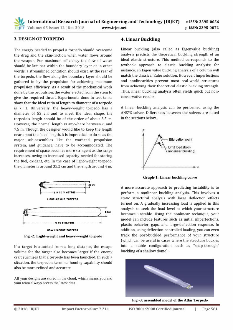
show that the ideal ratio of length to diameter of a torpedo
is 7: 1. Universally, the heavy-weight torpedo has a
diameter of 53 cm and to meet the ideal shape, the
torpedo's length should be of the order of about 3.5 m.
However, the normal length is anywhere between 6 and
7.5 m. Though the designer would like to keep the length
near about the. Ideal length, it is impractical to do so as the
major sub-assemblies like the warhead, propulsion
system, and guidance, have to be accommodated. The
requirement of space becomes more stringent as the range
increases, owing to increased capacity needed for storing
the fuel, oxidant, etc. In the case of light-weight torpedo,
the diameter is around 35.2 cm and the length around 4 m.
Fig -2: Light-weight and heavy-weight torpedo
If a target is attacked from a long distance, the escape
volume for the target also becomes larger if the enemy
craft surmises that a torpedo has been launched. In such a
situation, the torpedo's terminal homing capability should
also be more refined and accurate.
All your designs are stored in the cloud, which means you and
your team always access the latest data.
4. Linear Buckling
Linear buckling (also called as Eigenvalue buckling)
analysis predicts the theoretical buckling strength of an
ideal elastic structure. This method corresponds to the
textbook approach to elastic buckling analysis: for
instance, an Eigen value buckling analysis of a column will
match the classical Euler solution. However, imperfections
and nonlinearities prevent most real-world structures
from achieving their theoretical elastic buckling strength.
Thus, linear buckling analysis often yields quick but non-
conservative results.
A linear buckling analysis can be performed using the
ANSYS solver. Differences between the solvers are noted
in the sections below.
Graph-1: Linear buckling curve
A more accurate approach to predicting instability is to
perform a nonlinear buckling analysis. This involves a
static structural analysis with large deflection effects
turned on. A gradually increasing load is applied in this
analysis to seek the load level at which your structure
becomes unstable. Using the nonlinear technique, your
model can include features such as initial imperfections,
plastic behavior, gaps, and large-deflection response. In
addition, using deflection-controlled loading, you can even
track the post-buckled performance of your structure
(which can be useful in cases where the structure buckles
into a stable configuration, such as "snap-through"
buckling of a shallow dome).
Fig -3: assembled model of the Atlas Torpedo
International Research Journal of Engineering and Technology (IRJET) e-ISSN: 2395-0056
Volume: 05 Issue: 12 | Dec 2018 www.irjet.net p-ISSN: 2395-0072
© 2018, IRJET | Impact Factor value: 7.211 | ISO 9001:2008 Certified Journal | Page 582
5. Material and construction of Torpedo
Torpedo’s are made from corrosion resistant materials as
they are made operational directly in sea water which is a
corrosion accelerator. The materials used for making
Torpedos are alloy of aluminium and stainless steel. Other
materials used are alloys of nickel, aluminium and bronze
which are 10~15 % lighter than other materials and have
higher strength.
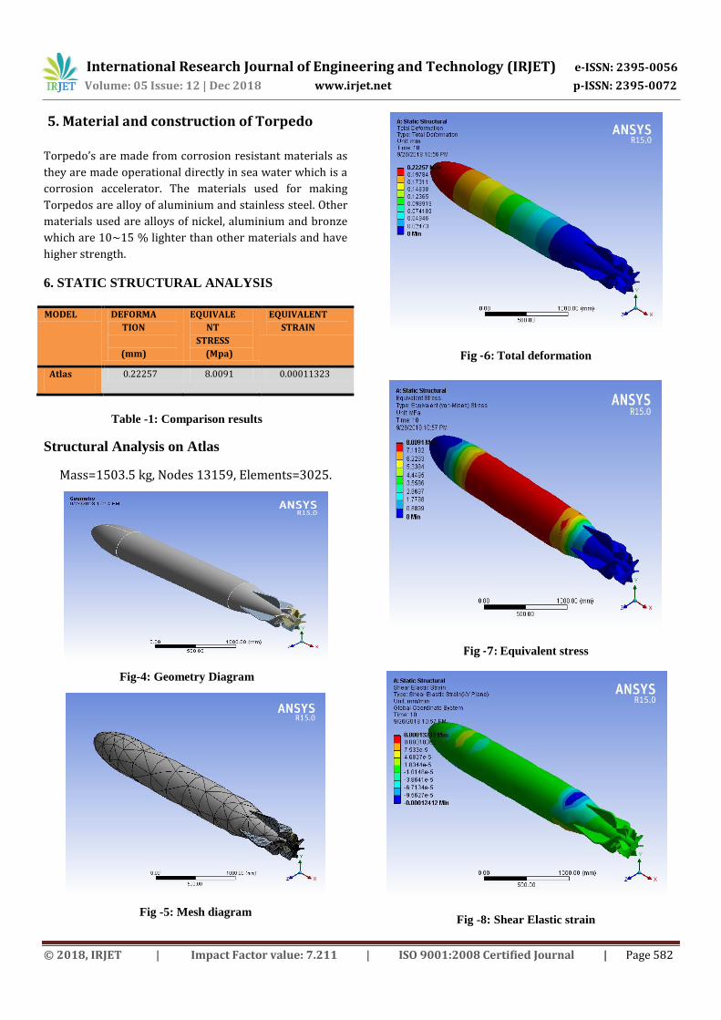
6. STATIC STRUCTURAL ANALYSIS
MODEL DEFORMA
TION
(mm)
EQUIVALE
NT
STRESS
(Mpa)
EQUIVALENT
STRAIN
Atlas 0.22257 8.0091 0.00011323
Table -1: Comparison results
Structural Analysis on Atlas
Mass=1503.5 kg, Nodes 13159, Elements=3025.
Fig-4: Geometry Diagram
Fig -5: Mesh diagram
Fig -6: Total deformation
Fig -7: Equivalent stress
Fig -8: Shear Elastic strain
International Research Journal of Engineering and Technology (IRJET) e-ISSN: 2395-0056
Volume: 05 Issue: 12 | Dec 2018 www.irjet.net p-ISSN: 2395-0072
© 2018, IRJET | Impact Factor value: 7.211 | ISO 9001:2008 Certified Journal | Page 583
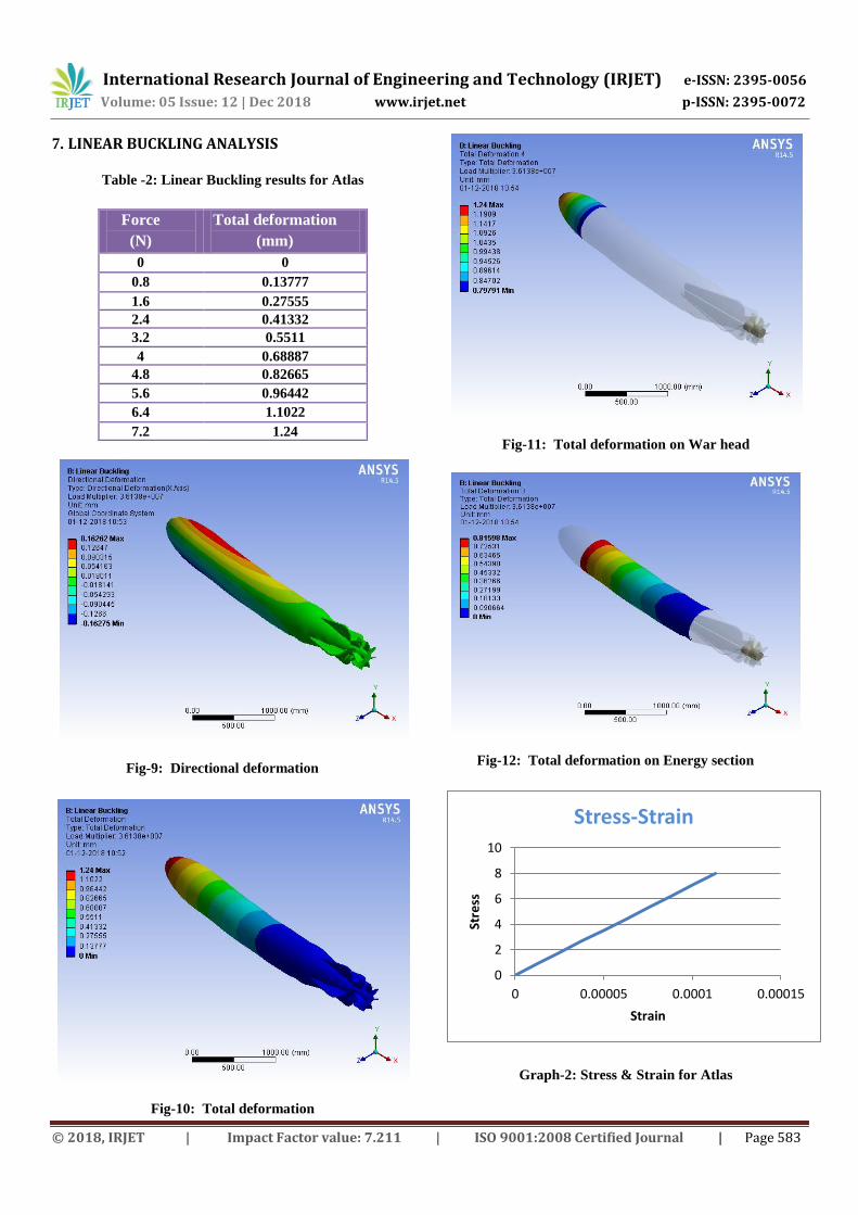
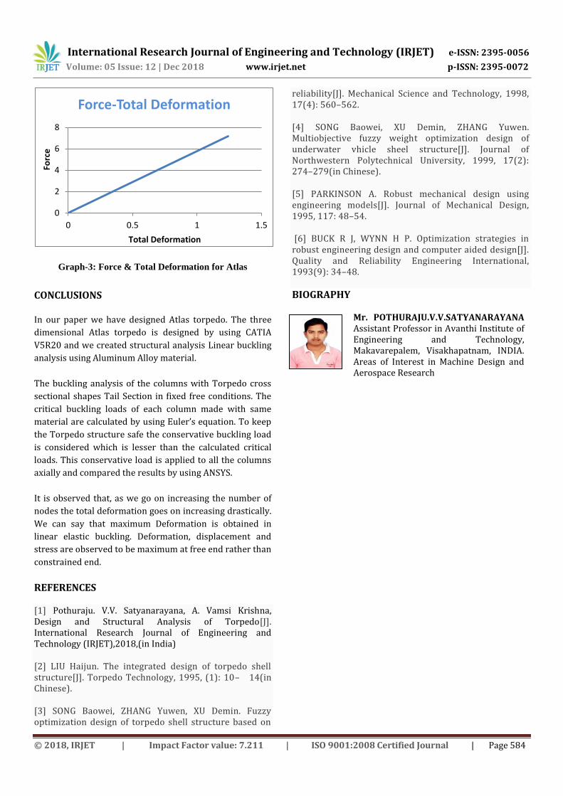
7. LINEAR BUCKLING ANALYSIS
Table -2: Linear Buckling results for Atlas
Force
(N)
Total deformation
(mm)
0 0
0.8 0.13777
1.6 0.27555
2.4 0.41332
3.2 0.5511
4 0.68887
4.8 0.82665
5.6 0.96442
6.4 1.1022
7.2 1.24
Fig-9: Directional deformation
Fig-10: Total deformation
Fig-11: Total deformation on War head
Fig-12: Total deformation on Energy section
Graph-2: Stress & Strain for Atlas
0
2
4
6
8
10
0 0.00005 0.0001 0.00015
Stre
ss
Strain
Stress-Strain
International Research Journal of Engineering and Technology (IRJET) e-ISSN: 2395-0056
Volume: 05 Issue: 12 | Dec 2018 www.irjet.net p-ISSN: 2395-0072
© 2018, IRJET | Impact Factor value: 7.211 | ISO 9001:2008 Certified Journal | Page 584
Graph-3: Force & Total Deformation for Atlas
CONCLUSIONS
In our paper we have designed Atlas torpedo. The three
dimensional Atlas torpedo is designed by using CATIA
V5R20 and we created structural analysis Linear buckling
analysis using Aluminum Alloy material.
The buckling analysis of the columns with Torpedo cross
sectional shapes Tail Section in fixed free conditions. The
critical buckling loads of each column made with same
material are calculated by using Euler’s equation. To keep
the Torpedo structure safe the conservative buckling load
is considered which is lesser than the calculated critical
loads. This conservative load is applied to all the columns
axially and compared the results by using ANSYS.
It is observed that, as we go on increasing the number of
nodes the total deformation goes on increasing drastically.
We can say that maximum Deformation is obtained in
linear elastic buckling. Deformation, displacement and
stress are observed to be maximum at free end rather than
constrained end.
REFERENCES
[1] Pothuraju. V.V. Satyanarayana, A. Vamsi Krishna, Design and Structural Analysis of Torpedo[J]. International Research Journal of Engineering and Technology (IRJET),2018,(in India)
[2] LIU Haijun. The integrated design of torpedo shell structure[J]. Torpedo Technology, 1995, (1): 10– 14(in Chinese).
[3] SONG Baowei, ZHANG Yuwen, XU Demin. Fuzzy optimization design of torpedo shell structure based on
reliability[J]. Mechanical Science and Technology, 1998, 17(4): 560–562.
[4] SONG Baowei, XU Demin, ZHANG Yuwen. Multiobjective fuzzy weight optimization design of underwater vhicle sheel structure[J]. Journal of Northwestern Polytechnical University, 1999, 17(2): 274–279(in Chinese).
[5] PARKINSON A. Robust mechanical design using engineering models[J]. Journal of Mechanical Design, 1995, 117: 48–54.
[6] BUCK R J, WYNN H P. Optimization strategies in robust engineering design and computer aided design[J]. Quality and Reliability Engineering International, 1993(9): 34–48.
BIOGRAPHY
Mr. POTHURAJU.V.V.SATYANARAYANA Assistant Professor in Avanthi Institute of Engineering and Technology, Makavarepalem, Visakhapatnam, INDIA. Areas of Interest in Machine Design and Aerospace Research
0
2
4
6
8
0 0.5 1 1.5
Forc
e
Total Deformation
Force-Total Deformation