Embed Size (px)
Citation preview

University of Arkansas, FayettevilleScholarWorks@UARK
Theses and Dissertations
8-2017
Linear DNA-Linked Nanoparticle Building Blocks(nBLOCKs) for Modular Self-Assembly ofNanostructuresJakob Thomas HockmanUniversity of Arkansas, Fayetteville
Follow this and additional works at: http://scholarworks.uark.edu/etd
Part of the Cell Biology Commons, and the Molecular Biology Commons
This Thesis is brought to you for free and open access by ScholarWorks@UARK. It has been accepted for inclusion in Theses and Dissertations by anauthorized administrator of ScholarWorks@UARK. For more information, please contact [email protected], [email protected].
Recommended CitationHockman, Jakob Thomas, "Linear DNA-Linked Nanoparticle Building Blocks (nBLOCKs) for Modular Self-Assembly ofNanostructures" (2017). Theses and Dissertations. 2439.http://scholarworks.uark.edu/etd/2439

Linear DNA-Linked Nanoparticle Building Blocks (nBLOCKs) for Modular Self-Assembly of
Nanostructures
A thesis submitted in partial fulfillment
of the requirements for the degree of
Master of Science in Cell and Molecular Biology
by
Jakob Hockman
University of Arkansas
Bachelor of Science in Biomedical Engineering, 2016
August 2017
University of Arkansas
This thesis is approved for recommendation to the Graduate Council.
______________________________________
Dr. Jin-Woo Kim
Thesis Director
______________________________________
Dr. Jingyi Chen
Committee Member
______________________________________
Dr. Joshua Sakon
Committee Member
______________________________________
Dr. Matthew Patitz
Committee Member
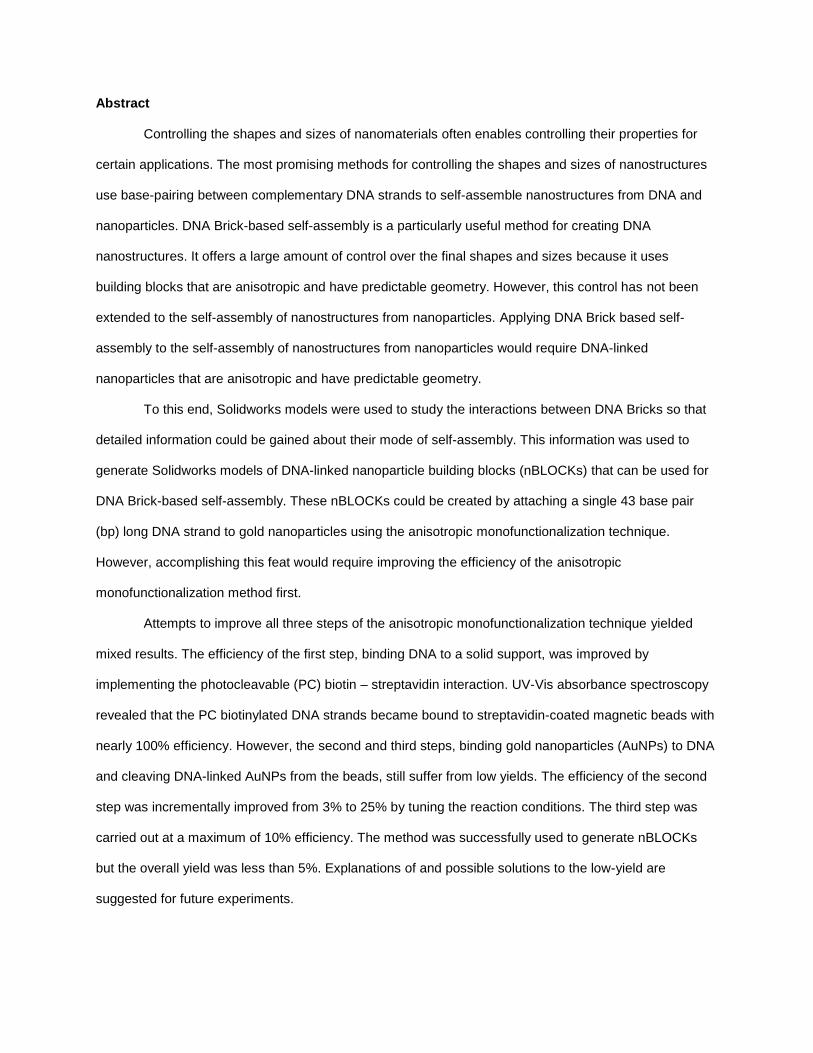
Abstract
Controlling the shapes and sizes of nanomaterials often enables controlling their properties for
certain applications. The most promising methods for controlling the shapes and sizes of nanostructures
use base-pairing between complementary DNA strands to self-assemble nanostructures from DNA and
nanoparticles. DNA Brick-based self-assembly is a particularly useful method for creating DNA
nanostructures. It offers a large amount of control over the final shapes and sizes because it uses
building blocks that are anisotropic and have predictable geometry. However, this control has not been
extended to the self-assembly of nanostructures from nanoparticles. Applying DNA Brick based self-
assembly to the self-assembly of nanostructures from nanoparticles would require DNA-linked
nanoparticles that are anisotropic and have predictable geometry.
To this end, Solidworks models were used to study the interactions between DNA Bricks so that
detailed information could be gained about their mode of self-assembly. This information was used to
generate Solidworks models of DNA-linked nanoparticle building blocks (nBLOCKs) that can be used for
DNA Brick-based self-assembly. These nBLOCKs could be created by attaching a single 43 base pair
(bp) long DNA strand to gold nanoparticles using the anisotropic monofunctionalization technique.
However, accomplishing this feat would require improving the efficiency of the anisotropic
monofunctionalization method first.
Attempts to improve all three steps of the anisotropic monofunctionalization technique yielded
mixed results. The efficiency of the first step, binding DNA to a solid support, was improved by
implementing the photocleavable (PC) biotin – streptavidin interaction. UV-Vis absorbance spectroscopy
revealed that the PC biotinylated DNA strands became bound to streptavidin-coated magnetic beads with
nearly 100% efficiency. However, the second and third steps, binding gold nanoparticles (AuNPs) to DNA
and cleaving DNA-linked AuNPs from the beads, still suffer from low yields. The efficiency of the second
step was incrementally improved from 3% to 25% by tuning the reaction conditions. The third step was
carried out at a maximum of 10% efficiency. The method was successfully used to generate nBLOCKs
but the overall yield was less than 5%. Explanations of and possible solutions to the low-yield are
suggested for future experiments.
Acknowledgements
I would like to thank the University of Arkansas Graduate School for their guidance in creating this
document. I would also like to thank Dr. Rhoads, the director of the Cell and Molecular Biology program,
for helping me find all of the information needed to complete this document.
I would like to thank my adviser, Dr. Kim, and the members of my advisory committee for their
guidance and support. I would also like to thank the members of the BNTG group for all of their help with
this project. A special thanks goes to Jeffrey (Curran) Henson for editing this document. I would also like
to express my sincere gratitude towards Mahshid Iraniparast and Dr. Arvind Sinha – I am truly grateful for
all the hard work you put in to help me finish.
Finally, I would like to thank my family and friends for all of their heartfelt support.

Dedication
To Dad, Mom, Kasey and Luke.
Table of Contents
1. Introduction ............................................................................................................................................... 1
1.1 Structural DNA Nanotechnology ......................................................................................................... 2
1.2 Self-Assembling Gold Nanostructures ................................................................................................ 9
1.3 Anisotropic Monofunctionalization “One-At-A-Time” Method ............................................................ 12
1.4 Thesis Objectives .............................................................................................................................. 18
2. Materials and Methods ............................................................................................................................ 19
2.1 Materials. ........................................................................................................................................... 19
2.2 Computer Modelling. ......................................................................................................................... 19
2.3 DNA-Functionalization of AuNPs. ..................................................................................................... 19
2.4 Characterization ................................................................................................................................ 20
3. Results and Discussion ........................................................................................................................... 21
3.1 Modelling the Self-Assembly of DNA Bricks and nBLOCKs ............................................................. 21
3.2 Improving the Efficiency of the Anisotropic Monofunctionalization Technique ................................. 34
4. Conclusion .............................................................................................................................................. 46
5. Future Work ............................................................................................................................................ 47
6. References .............................................................................................................................................. 49
Appendix A: Strand Sequences for Small nBLOCK cube nanostructures .................................................. 52

List of Figures
Figure 1. Strategy of DNA Origami [16] .................................................................................................... 3
Figure 2. Nanostructures created using DNA Origami [16] .................................................................... 4
Figure 3. Strand displacement reaction leading to the opening of a DNA origami lockbox [19] ....... 5
Figure 4. Periodic DNA building block in the shape of tensegrity triangle [22] ................................... 5
Figure 5. DNA Brick method of self-assembly [23 ................................................................................... 7
Figure 6. Nanostructures created using DNA Bricks [23] ....................................................................... 8
Figure 7. DNA Origami scaffold used to self-assemble nanostructures of AuNPs [38] .................... 10
Figure 8. DNA Brick scaffold used to create nanostructures from AuNPs [39] ................................. 10
Figure 9. Isotropically functionalized AuNPs can be used to create nanostructures from the inside
out (modified from [40]) ............................................................................................................................ 11
Figure 10. Summary of Anisotropic Monofunctionalization Technique [32] ...................................... 13
Figure 11. TEM characterization of nBLOCK geometries (modified from [32]) .................................. 14
Figure 12. Current limitations of nBLOCKs (modified from [32])......................................................... 16
Figure 13. Adaptation of DNA Brick-based self-assembly for linear nBLOCKs (modified from [23])
.................................................................................................................................................................... 17
Figure 14. Formation of DNA Bricks from Linear ssDNA ..................................................................... 22
Figure 15. Rigidity of dsDNA.................................................................................................................... 23
Figure 16. Abstract model of DNA Bricks (adapted from [23]) ............................................................. 24
Figure 17. Modified DNA Bricks with cavity for nanoparticles............................................................. 26
Figure 18. Different possible geometries of nBLOCKs with one DNA strand attached .................... 27
Figure 19. Creation of nanostructures from the inside-out using linear nBLOCKs with one DNA
strand attached ......................................................................................................................................... 29
Figure 20. nBLOCKs with two DNA strands attached are not as rigid as dsDNA .............................. 31
Figure 21. Creation of nanostructures from linear nBLOCKs with two DNA strands attached ........ 32
Figure 22. The anisotropic monofunctionalization technique .............................................................. 35
Figure 23. DNA binding to streptavidin coated magnetic beads ......................................................... 37
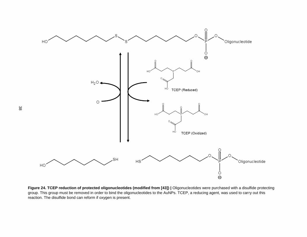
Figure 24. TCEP reduction of protected oligonucleotides (modified from [43]) ................................ 38
Figure 25. Preparing AuNPs and binding DNA ...................................................................................... 39
Figure 26. Summary of attempts to increase efficiency of AuNP ....................................................... 40
Figure 27. Photocleavage of PC biotin using UV light (adapted from [45]) ........................................ 42
Figure 28. Efficiency of Photocleavage in H2O ...................................................................................... 43
Figure 29. Efficiency of Photocleavage in Buffer .................................................................................. 45
1
1. Introduction
There is an overarching goal within the field of nanotechnology to control the size and shape of
nanostructures because many nanomaterials have size and shape dependent properties. Methods that
allow researchers to control the overall size and shape of nanostructures also allow them to tune their
material properties for specific applications.
For example, attempts to self-assemble structures from gold nanoparticles (AuNPs) are motivated in part
by gold’s size and shape dependent localized surface plasmon (LSP) [1-5]. LSP is the collective
oscillation of electrons around a nanoparticle in response to incident light. The phenomenon known as
plasmon coupling causes electrons within a certain distance of each other (< 5nm) to synchronize their
oscillations [6].
The LSP has a resonant frequency at which energy transmission is maximized. Changing the size and
shape of the nanoparticle changes the number and relative positions of the electrons in range of plasmon
coupling which in turn changes the LSP resonant frequency. LSP causes nanoparticles to vibrate which in
turn generates heat and pressure waves.
One specialized application of these size and shape dependent properties is in cancer theranostics
(therapy and diagnostics) [7-11]. By tuning the size and shape of AuNP nanostructures, their resonant
LSP frequency can be tuned to near-infrared (NIR) light, to which human tissues are maximally
transparent. Antibody-conjugated AuNPs injected into the bloodstream will seek out and bind to tumors
through specific antibody-antigen interactions. NIR light can then be shined through human tissues to
where the nanoparticles are bound on the tumor cells. The resulting mechanical vibrations generate
pressure waves that can be detected using an ultrasound device. At high enough concentrations, the
mechanical vibrations also generate enough heat to destroy the tumor cells.
2
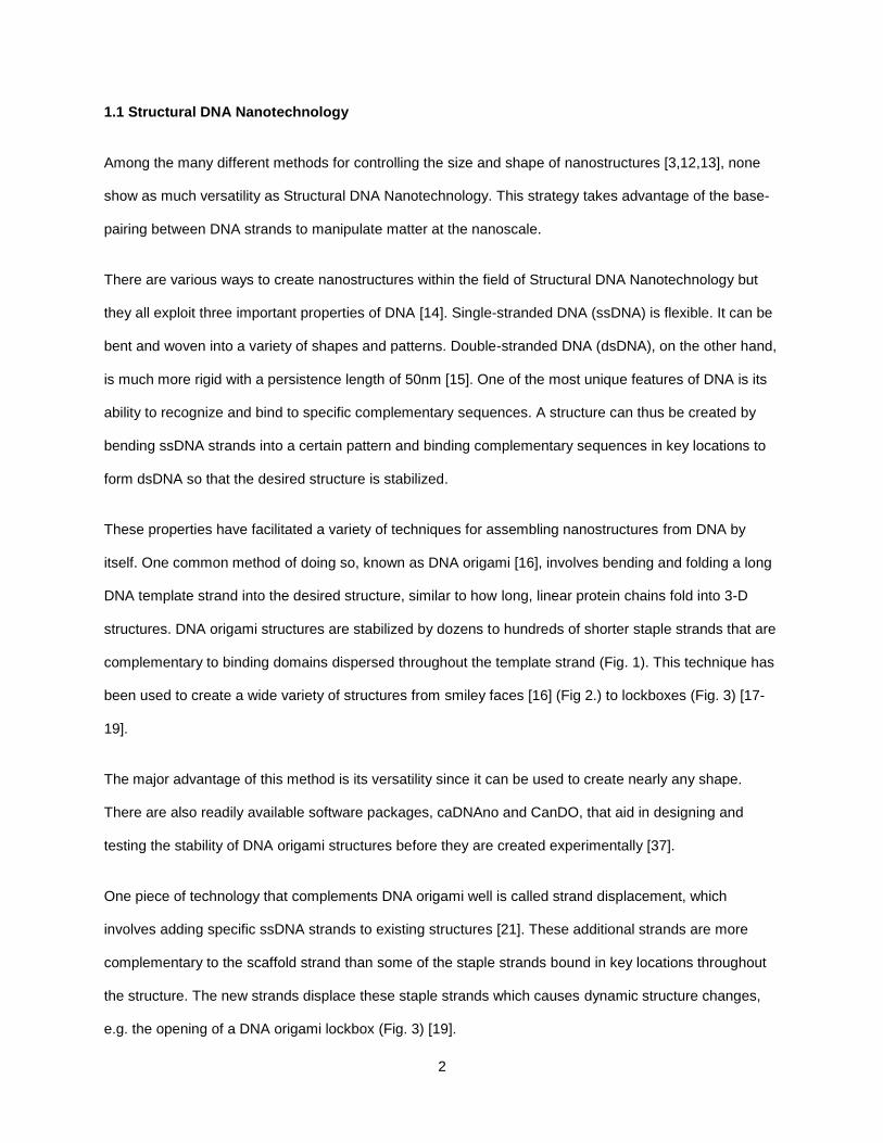
1.1 Structural DNA Nanotechnology
Among the many different methods for controlling the size and shape of nanostructures [3,12,13], none
show as much versatility as Structural DNA Nanotechnology. This strategy takes advantage of the base-
pairing between DNA strands to manipulate matter at the nanoscale.
There are various ways to create nanostructures within the field of Structural DNA Nanotechnology but
they all exploit three important properties of DNA [14]. Single-stranded DNA (ssDNA) is flexible. It can be
bent and woven into a variety of shapes and patterns. Double-stranded DNA (dsDNA), on the other hand,
is much more rigid with a persistence length of 50nm [15]. One of the most unique features of DNA is its
ability to recognize and bind to specific complementary sequences. A structure can thus be created by
bending ssDNA strands into a certain pattern and binding complementary sequences in key locations to
form dsDNA so that the desired structure is stabilized.
These properties have facilitated a variety of techniques for assembling nanostructures from DNA by
itself. One common method of doing so, known as DNA origami [16], involves bending and folding a long
DNA template strand into the desired structure, similar to how long, linear protein chains fold into 3-D
structures. DNA origami structures are stabilized by dozens to hundreds of shorter staple strands that are
complementary to binding domains dispersed throughout the template strand (Fig. 1). This technique has
been used to create a wide variety of structures from smiley faces [16] (Fig 2.) to lockboxes (Fig. 3) [17-
19].
The major advantage of this method is its versatility since it can be used to create nearly any shape.
There are also readily available software packages, caDNAno and CanDO, that aid in designing and
testing the stability of DNA origami structures before they are created experimentally [37].
One piece of technology that complements DNA origami well is called strand displacement, which
involves adding specific ssDNA strands to existing structures [21]. These additional strands are more
complementary to the scaffold strand than some of the staple strands bound in key locations throughout
the structure. The new strands displace these staple strands which causes dynamic structure changes,
e.g. the opening of a DNA origami lockbox (Fig. 3) [19].

3
Figure 1. Strategy of DNA Origami [16] | DNA origami involves folding a long circular DNA molecule (template strand) into shapes using dozens to hundreds of staple strands. The staple strands bring together distant regions of the molecule and stabilize them in specific positions.
4
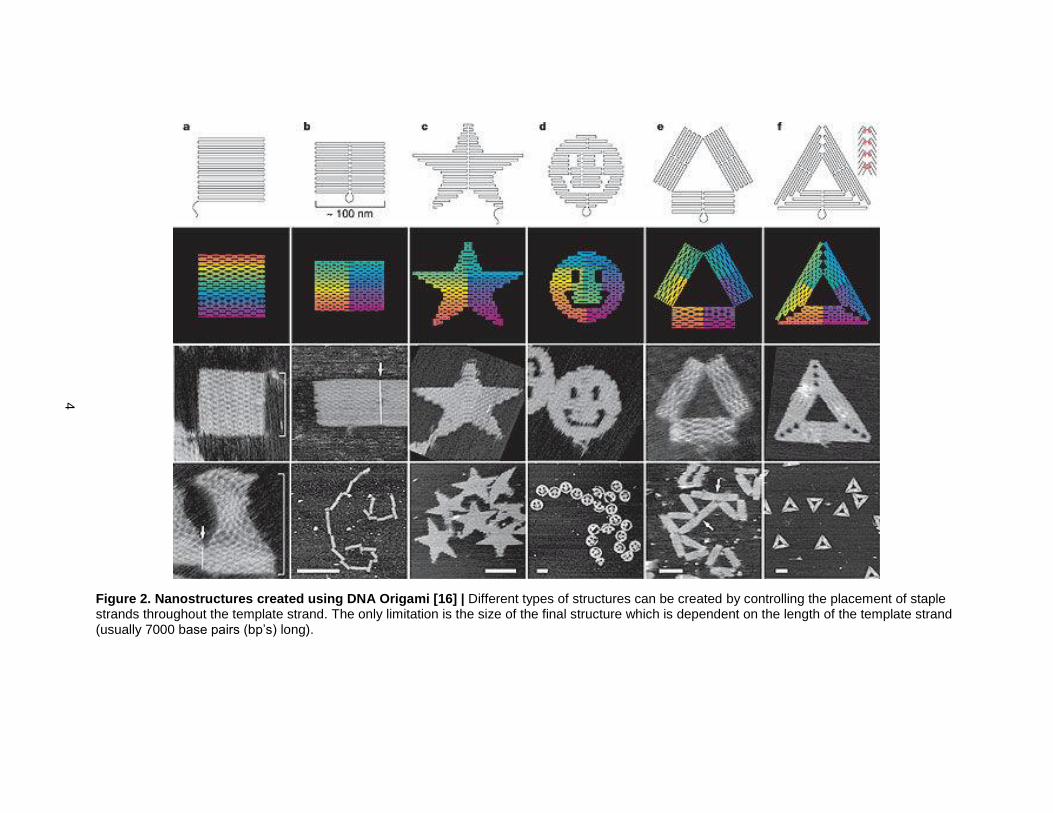
Figure 2. Nanostructures created using DNA Origami [16] | Different types of structures can be created by controlling the placement of staple strands throughout the template strand. The only limitation is the size of the final structure which is dependent on the length of the template strand (usually 7000 base pairs (bp’s) long).

5
Figure 3. Strand displacement reaction leading to the opening of a DNA origami lockbox [19] | A
box with a controllable lid was created using DNA origami and strand displacement reactions. DNA
origami was used to create the geometry of the box itself. A strand displacement reaction involving
ssDNA “keys” resulted in the displacement of the strands holding the box closed, which caused the lid to
open.
Figure 4. Periodic DNA building block in the shape of tensegrity triangle [22] | A. Schematic of the strand sequences used to form a tensegrity triangle. Sticky ends (red) interact with one another in a repetitive manner to build up a crystal lattice. B. 3-dimensional model of interactions between tensegrity triangles that lead to crystallization. C. Macroscopic DNA crystals made from these tensegrity triangles
measuring .25 mm.
6
Another method of creating DNA nanostructures involves creating building blocks that stack on top of one
other to form larger structures. This strategy can be further subdivided based on the interactions between
building blocks. One strategy uses multiple identical DNA building blocks that interact periodically to
create lattices. For example, a tensegrity triangle building block with self-complementary sticky ends was
successfully used to create a 3-dimensional DNA crystal that could be seen with the naked eye (Fig. 4)
[22]. The benefits of this strategy are its simplicity and scalability – only a few building blocks are needed
to create structures that can be expanded to nearly any scale. The major limitation is that there is little
control over the final shape of the resulting nanostructures since the building blocks stack uncontrollably.
A different method of assembling nanostructures from DNA involves designing unique interactions for
every DNA building block in an assembly. An excellent example of this “hard-coding” approach is the self-
assembly of DNA Bricks [23,24]. Each DNA Brick is a linear 32 base pair (bp) long ssDNA strand that
folds back on itself in between bp’s 16 and 17, creating two parallel helices (Fig. 5). These parallel helices
interact with four others through four 8 bp binding domains. Each 8bp domain causes a 2700 turn of the
DNA helix. This helical turning causes every binding partner of the parallel helices to be oriented at 2700
angles from each other. Each ssDNA strand is effectively a “brick” that stacks with other bricks in a
specific orientation. When hundreds to thousands of these building blocks come together, they pack
together very tightly and form nanostructures (Fig. 6)
The keys to this technology are anisotropy and predictable geometry. Each building block is anisotropic
which means that they all have unique interactions with their neighbors. Anisotropy is extremely powerful
in building nanostructures since only the desired interactions between building blocks take place, which
creates a way to control the final shapes and sizes of the structures. Predictable geometry allows for
consistent interactions to occur between building blocks so that they stack up on top of one another in a
predictable manner. This predictability aids in designing structures since the relative orientations of all the
building blocks are known. The only limitation to this method is the large number of unique building blocks
required to create each structure. Many of the structures require hundreds to thousands of unique DNA
strands. Designing their interactions can be complicated so there are software packages (e.g. 3DNA [43])
that automatically design the DNA Brick sequences to form the desired structures.

7
Figure 5. DNA Brick method of self-assembly [23] | A. DNA Bricks are formed from 32 bp ssDNA strands with a fold in between the 16th and 17th base pairs. B. Each Brick has 4 binding domains, each consisting of 8 bps. These domains can be abstractly represented as pegs and holes in “Bricks”. C. Each 8 bp binding domain causes a 2700 turn of the helix. Each 2700 binding domain orients its binding partners at a 900 angle from all of its other binding partners. D. This system allows the Bricks to pack together very tightly and self-assemble into predetermined shapes. E. Interactions can be customized so that each set of Bricks forms a unique structure. F. A cube can be created from a specific set of Bricks. By
leaving out some of these bricks, new structures can be created without having to design new interactions or purchase new DNA strands.

8
Figure 6. Nanostructures created using DNA Bricks [23] | A. Researchers created a set of sequences that form a 10x10x10 cube structure. B. By leaving out key bricks, certain types of geometries could be formed. C. These strand sequences were selected using the help of a software program and added together in the lab using an automated robot. D. The correct structures were separated using gel electrophoresis and characterized using a TEM microscope. E. Various structures were created using this
method, from letters to emojis.

9
One final approach that attempts to merge these two methods is called algorithmic self-assembly.
Algorithmic self-assembly involves creating building blocks that adhere to a certain set of rules [25,26] so
that they stack up on top of each other in a predictable manner. These building blocks also require
anisotropy and predictable geometry. However, one additional variable is the strength of binding between
building blocks. Tuning this strength allows for the building blocks to be reused in very specific locations
throughout the assembly as determined by an algorithm contained in the DNA building blocks and the
temperature of the system. This method is extremely powerful in that it matches the versatility of the hard-
coding approach with the smaller number of building blocks championed by the periodic approach.
However, it is generally much more difficult to create these building blocks which is why they are more
limited in use.
1.2 Self-Assembling Gold Nanostructures
Any structures created using one of the above methods can be functionalized with sticky ends on which
external DNA strands can bind. AuNPs can then be attached to these structures by attaching to them to
complementary DNA strands and binding them to the sticky ends. These DNA-linked AuNPs can also
serve as building blocks themselves if they can interact with one another in one of the manners described
above. Thus, many methods have emerged to create different types of DNA-linked AuNPs depending on
the desired applications.
One such method, known as isotropic functionalization, involves directly adding nanoparticles to a
solution of free floating DNA strands so that many different copies of the same strand coats the surface of
each nanoparticle. These DNA-linked nanoparticles can then be used to pattern the surface of DNA
origami (Fig. 7) and DNA Brick (Fig. 8) structures [27-29]. The major advantage of creating AuNP
nanostructures this way is that nearly any structure that can be built using DNA origami or DNA Bricks
can be used to pattern AuNPs. However, the primary limitation of these strategies is that they can only be
used to pattern nanoparticles on the surface of the structures. It would be difficult to create structures of
AuNPs from the inside-out using either of these two methods.

10
Figure 7. DNA Origami scaffold used to self-assemble nanostructures of AuNPs [38] | A. Illustration
showing how the DNA scaffold interacts with the DNA-bound AuNPs through complementary sticky ends.
B. TEM images of nanostructures with precise placement of the nanoparticles on the surface of DNA
scaffolds.
Figure 8. DNA Brick scaffold used to create nanostructures from AuNPs [39] | Illustration showing
how DNA Brick scaffolds can be used to pattern AuNPs. It is possible to precisely place AuNPs on the
surface of these structures.

11
Figure 9. Isotropically functionalized AuNPs can be used to create nanostructures from the inside out (modified from [40] | Sets of
nanoparticles with different complementary DNA strands or self-complementary DNA strands can be used to self-assemble nanostructures with
different lattice structures.

12
To create structure made entirely of DNA-linked AuNPs, many researchers have begun using isotropically
functionalized AuNPs as periodic DNA-linked building blocks (Fig. 9). To date, face-centered cubic and
body-centered cubic lattices are the only structures to have been created using this method [30-31]. The
major limitation of these building blocks is that it is difficult to control their interactions so that they self-
assemble into arbitrary shapes – there is no way to control the overall size and shape of the
nanostructures that they form.
1.3 Anisotropic Monofunctionalization “One-At-A-Time” Method
To overcome these limitations, it would be necessary to create building blocks with the anisotropy and
predictable geometry needed for the hard-coded self-assembly method. Creating these building blocks
requires a different method of functionalization.
A more powerful method of attaching DNA to AuNPs is the anisotropic monofunctionalization “one-at-a-
time” technique [32,41] (Fig. 10). This method involves controlling the number, composition, and
orientation of each DNA strand that binds to the surface of an AuNP. These building blocks have DNA
strands that are oriented symmetrically in one (linear geometry), two (square planar geometry), or three
dimensions (octahedral geometry). Each DNA strand is also unique since they are attached one at a time.
Thus, the 3-dimensional nBLOCKs appear to have both predictable geometry and anisotropy which would
make them ideal for creating hard-coding nanostructures. However, to date, these building blocks have
not been used to create 3-dimensional structures due to the related problems of complexity and
inefficiency.
The overall efficiency of the anisotropic monofunctionalization method is determined by the combined
efficiencies of three cyclic steps. The first step is to bind DNA strands to a solid-support (e.g. magnetic
beads). The solid support has specific locations on which the DNA molecules can bind so that the strands
are spaced apart. The second step is to bind the AuNPs to the DNA. Because the DNA strands are
spaced apart on the surface of the solid support, each AuNP binds to only one DNA strand at a time. The
third step is to cleave the DNA-linked AuNPs from the beads and collect them.

13
Figure 10. Summary of Anisotropic Monofunctionalization Technique [32] | DNA is spaced apart on the surface of a solid support. AuNPs are added and the space between the DNA strands prevents more than one of them from binding to each AuNP. The DNA-linked AuNPs are cleaved from the beads and collected. This process can be repeated up to six times to create nBLOCKs with different geometries.

14
Figure 11. TEM characterization of nBLOCK geometries (modified from [32]) | (Left) TEM images of the nBLOCK geometries. (Right) 3-
dimensional analysis showing the ability to create nBLOCKs with specific geometries.
15
Repeating the monofunctionalization steps a second time binds a second DNA strand to the particle at a
different location. Electrostatic repulsion and steric hindrance between the two negatively charged DNA
molecules causes the new strand to bind as far away from the first as possible, i.e. on the opposite face
of the particle (Fig. 11). An nBLOCK with two DNA strands attached thus has linear geometry. The third
DNA strand will attach in between the previous two at 900 angles to both. The fourth DNA strand will bind
at 1800 from the third strand and at 900 angles from the other two, creating a square planar geometry.
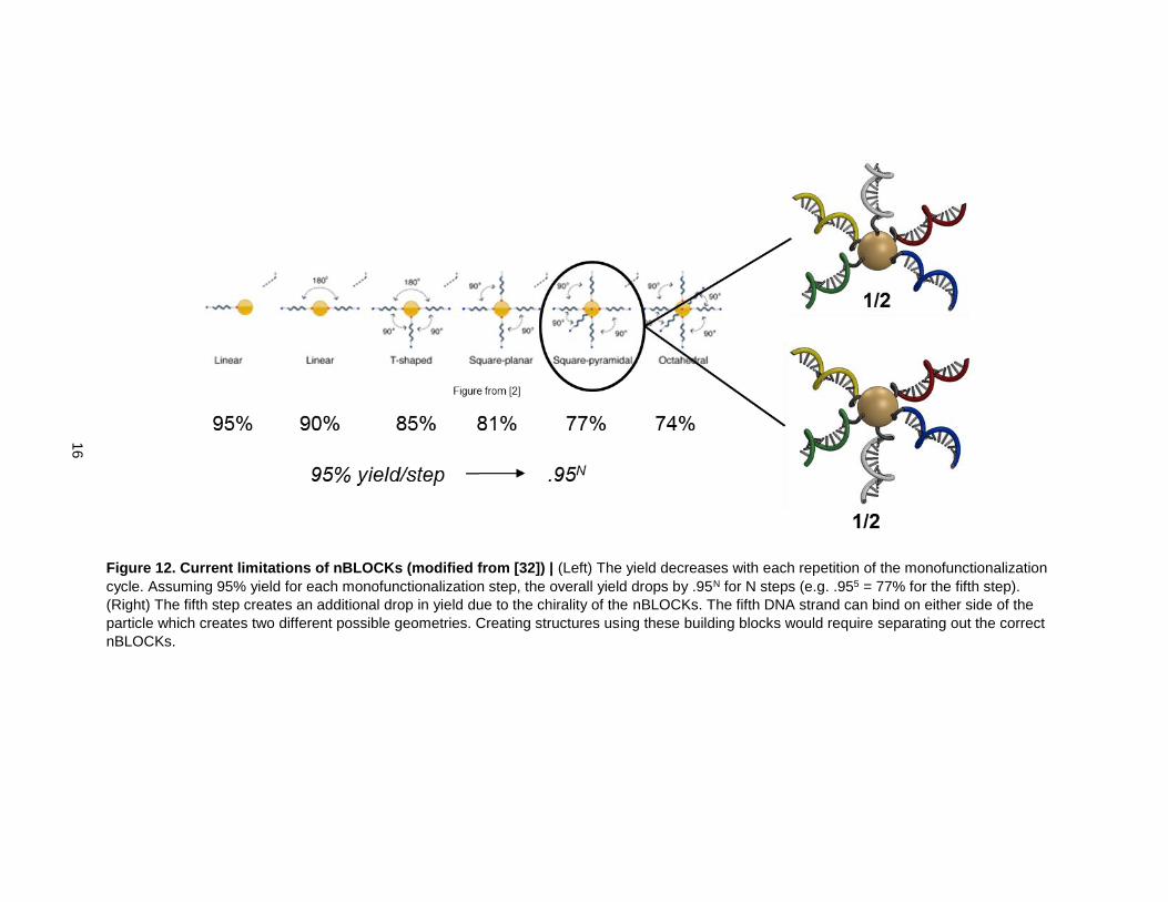
The 5th DNA strand can attach on either side of the plane created by the four other DNA strands. Because
of this, there is a 50% chance of the fifth and sixth strands attaching in an undesired orientation on the
AuNP, which cuts the yield for creating these 3-dimensional nBLOCKs in half (Fig. 12). Creating
structures using these nBLOCKs would require isolating the correctly formed nBLOCKs, which would be
difficult.
The overall yield of the method also drops with each repetition of the cycle (Fig. 12). Assuming there is a
high yield for attaching AuNPs to the DNA (e.g. 95%), each repetition of the steps causes a further drop
in yield (.955 for 5 steps, or 77%). Thus, creating structures using more complex building blocks results in
lower yields.
To summarize, the two primary limitations of using 3-dimensional nBLOCKs to build modular
nanostructures are: (1) the yield decreases with each repetition of the monofunctionalization steps and (2)
the chirality of 3-dimensionally symmetric nBLOCKs makes it more difficult to create structures without
separating out the desired nBLOCKs. To overcome these issues, it would be useful to create structures
using one of the simpler building blocks (i.e. linear nBLOCKs).
Accomplishing this task will require a new strategy for designing the interactions between nBLOCKs.
DNA Brick-based self-assembly offers a strategy for creating complex nanostructures using linear building
blocks (Fig 13). By applying DNA Brick-based self-assembly to nBLOCKs, it would be theoretically
possible to create modular nanostructures from the inside out using DNA-linked AuNPs.
16
Figure 12. Current limitations of nBLOCKs (modified from [32]) | (Left) The yield decreases with each repetition of the monofunctionalization
cycle. Assuming 95% yield for each monofunctionalization step, the overall yield drops by .95N for N steps (e.g. .955 = 77% for the fifth step).
(Right) The fifth step creates an additional drop in yield due to the chirality of the nBLOCKs. The fifth DNA strand can bind on either side of the
particle which creates two different possible geometries. Creating structures using these building blocks would require separating out the correct
nBLOCKs.

17
Figure 13. Adaptation of DNA Brick-based self-assembly for linear nBLOCKs (modified from [23]) | Because of the similarities between the
two linear building blocks, it is theoretically possible to adapt DNA Brick-based self-assembly to the self-assembly of linear nBLOCKs. This would
allow for the creation of AuNP nanostructures from the inside out with precise control over their final size and shape.

18
1.4 Thesis Objectives
The goal of this thesis is to reduce the complexity and improve the efficiency creating modular
nanostructures from nBLOCKs. In order to accomplish this goal, it will be necessary to complete two
objectives.
The first objective is to use computer models to study the self-assembly of DNA Bricks and nBLOCKs.
DNA Brick-based self-assembly will be studied in some detail so that its unique features can be applied to
the self-assembly of nanostructures from linear nBLOCKs. The information gained will be used to design
interactions between linear nBLOCKs so that they self-assemble into nanostructures in a similar manner.
The second objective is to improve the three steps of the anisotropic monofunctionalization method so
that the linear nBLOCKs required for structure building can be reliably produced.
19
2. Materials and Methods
2.1 Materials.
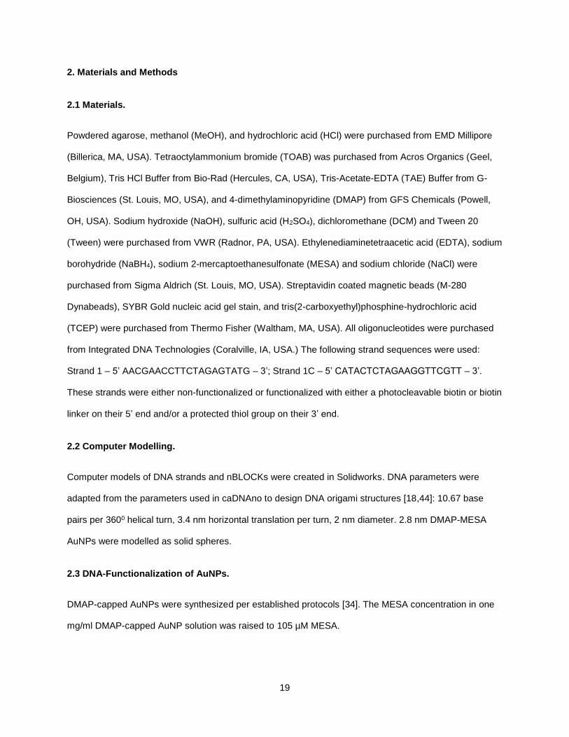
Powdered agarose, methanol (MeOH), and hydrochloric acid (HCl) were purchased from EMD Millipore
(Billerica, MA, USA). Tetraoctylammonium bromide (TOAB) was purchased from Acros Organics (Geel,
Belgium), Tris HCl Buffer from Bio-Rad (Hercules, CA, USA), Tris-Acetate-EDTA (TAE) Buffer from G-
Biosciences (St. Louis, MO, USA), and 4-dimethylaminopyridine (DMAP) from GFS Chemicals (Powell,
OH, USA). Sodium hydroxide (NaOH), sulfuric acid (H2SO4), dichloromethane (DCM) and Tween 20
(Tween) were purchased from VWR (Radnor, PA, USA). Ethylenediaminetetraacetic acid (EDTA), sodium
borohydride (NaBH4), sodium 2-mercaptoethanesulfonate (MESA) and sodium chloride (NaCl) were
purchased from Sigma Aldrich (St. Louis, MO, USA). Streptavidin coated magnetic beads (M-280
Dynabeads), SYBR Gold nucleic acid gel stain, and tris(2-carboxyethyl)phosphine-hydrochloric acid
(TCEP) were purchased from Thermo Fisher (Waltham, MA, USA). All oligonucleotides were purchased
from Integrated DNA Technologies (Coralville, IA, USA.) The following strand sequences were used:
Strand 1 – 5’ AACGAACCTTCTAGAGTATG – 3’; Strand 1C – 5’ CATACTCTAGAAGGTTCGTT – 3’.
These strands were either non-functionalized or functionalized with either a photocleavable biotin or biotin
linker on their 5’ end and/or a protected thiol group on their 3’ end.
2.2 Computer Modelling.
Computer models of DNA strands and nBLOCKs were created in Solidworks. DNA parameters were
adapted from the parameters used in caDNAno to design DNA origami structures [18,44]: 10.67 base
pairs per 3600 helical turn, 3.4 nm horizontal translation per turn, 2 nm diameter. 2.8 nm DMAP-MESA
AuNPs were modelled as solid spheres.
2.3 DNA-Functionalization of AuNPs.
DMAP-capped AuNPs were synthesized per established protocols [34]. The MESA concentration in one
mg/ml DMAP-capped AuNP solution was raised to 105 µM MESA.

20
To bind DNA to the solid support, 10 µl of streptavidin-coated magnetic beads (.01 mg) were washed
twice with 1.5 ml of DNA Binding Buffer containing Tween (5 mM Tris HCl, 1 M NaCl, .05% Tween, pH
7.4) and once with 1.5 ml DNA Binding Buffer (5 mM Tris HCl, 1 M NaCl, pH 7.4) with five minutes of
gentle mixing during each washing step. Two hundred µl of 500 nM oligonucleotide in DNA Binding Buffer
was added to the beads and left to incubate for 1 hr.
To bind AuNPs, the resulting DNA-conjugated beads were washed twice with 1.5 ml of 1x TE Buffer
containing Tween (10 mM Tris HCl, 1 mM EDTA, .05% Tween, pH 7.4) and once with 1x TE Buffer (10
mM Tris HCl, 1 mM EDTA, pH 7.4) under nitrogen. One ml of 3.5 µM TCEP in 1x TE Buffer was added
and the mixture was incubated at 37oC. After 1 hr of incubation, the TCEP solution was replaced with
fresh 3.5 µM TCEP solution under nitrogen and allowed to incubate for an additional 1 hr at the same
temperature. After TCEP reduction, the beads were washed twice with 1.5 ml ddH2O containing Tween
(.05% Tween) and twice with ddH2O under nitrogen. 450 µl of .2 µM DMAP-MESA AuNPs in ddH2O were
added and the solution was left to incubate overnight.
To cleave the DNA-bound AuNPs, the AuNP-bound-beads were washed 2x more in 1.5 ml of ddH2O
containing Tween, 2x in 1.5 ml of ddH2O and finally resuspended in 200 µl of ddH2O. The sample was
irradiated with UV light (Luxo UV-Inspection Lamp) for 15 minutes. After magnetic separation, the
supernatants of the samples were collected and characterized.
2.4 Characterization
UV-Visible absorbance spectra were collected using a Thermo Fisher Nanodrop 2000C. Extinction
coefficients obtained from Integrated DNA Technologies were used to calculate DNA concentrations
using the A260 value. The diameter of the AuNPs was calculated using the Apeak/A450 ratio [42]. This value
was used to calculate the extinction coefficient using the logarithmic relationship between diameter and ε
[35]. For data analysis, the concentration drops in the supernatants after DNA binding or AuNP binding
were compared against control samples (non-functionalized DNA for DNA Binding and non-TCEP-
activated DNA strands for AuNP binding).
21
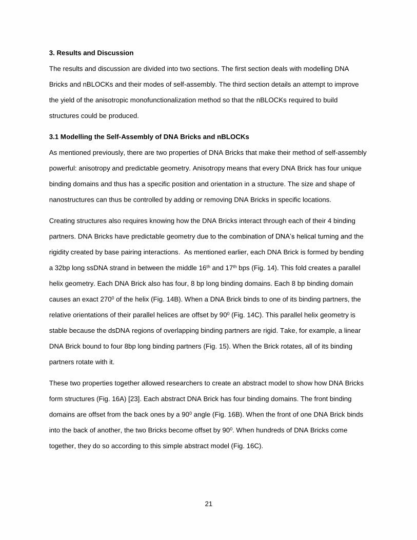
3. Results and Discussion
The results and discussion are divided into two sections. The first section deals with modelling DNA
Bricks and nBLOCKs and their modes of self-assembly. The third section details an attempt to improve
the yield of the anisotropic monofunctionalization method so that the nBLOCKs required to build
structures could be produced.
3.1 Modelling the Self-Assembly of DNA Bricks and nBLOCKs
As mentioned previously, there are two properties of DNA Bricks that make their method of self-assembly
powerful: anisotropy and predictable geometry. Anisotropy means that every DNA Brick has four unique
binding domains and thus has a specific position and orientation in a structure. The size and shape of
nanostructures can thus be controlled by adding or removing DNA Bricks in specific locations.
Creating structures also requires knowing how the DNA Bricks interact through each of their 4 binding
partners. DNA Bricks have predictable geometry due to the combination of DNA’s helical turning and the
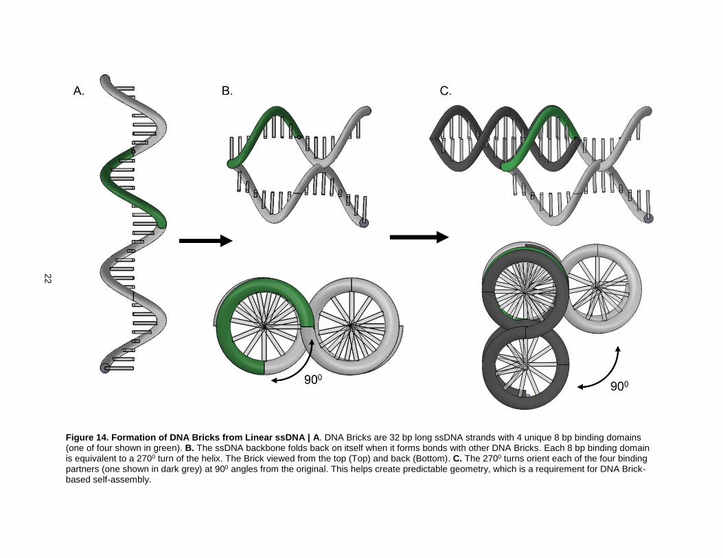
rigidity created by base pairing interactions. As mentioned earlier, each DNA Brick is formed by bending
a 32bp long ssDNA strand in between the middle 16th and 17th bps (Fig. 14). This fold creates a parallel
helix geometry. Each DNA Brick also has four, 8 bp long binding domains. Each 8 bp binding domain
causes an exact 2700 of the helix (Fig. 14B). When a DNA Brick binds to one of its binding partners, the
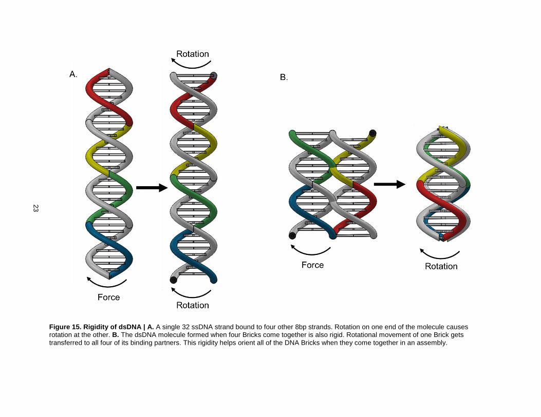
relative orientations of their parallel helices are offset by 900 (Fig. 14C). This parallel helix geometry is
stable because the dsDNA regions of overlapping binding partners are rigid. Take, for example, a linear
DNA Brick bound to four 8bp long binding partners (Fig. 15). When the Brick rotates, all of its binding
partners rotate with it.
These two properties together allowed researchers to create an abstract model to show how DNA Bricks
form structures (Fig. 16A) [23]. Each abstract DNA Brick has four binding domains. The front binding
domains are offset from the back ones by a 900 angle (Fig. 16B). When the front of one DNA Brick binds
into the back of another, the two Bricks become offset by 900. When hundreds of DNA Bricks come
together, they do so according to this simple abstract model (Fig. 16C).
22
Figure 14. Formation of DNA Bricks from Linear ssDNA | A. DNA Bricks are 32 bp long ssDNA strands with 4 unique 8 bp binding domains (one of four shown in green). B. The ssDNA backbone folds back on itself when it forms bonds with other DNA Bricks. Each 8 bp binding domain is equivalent to a 2700 turn of the helix. The Brick viewed from the top (Top) and back (Bottom). C. The 2700 turns orient each of the four binding partners (one shown in dark grey) at 900 angles from the original. This helps create predictable geometry, which is a requirement for DNA Brick-based self-assembly.
23
Figure 15. Rigidity of dsDNA | A. A single 32 ssDNA strand bound to four other 8bp strands. Rotation on one end of the molecule causes rotation at the other. B. The dsDNA molecule formed when four Bricks come together is also rigid. Rotational movement of one Brick gets transferred to all four of its binding partners. This rigidity helps orient all of the DNA Bricks when they come together in an assembly.

24
Figure 16. Abstract model of DNA Bricks (adapted from [23]) | A. Each DNA Brick can be abstractly modelled as a brick with four binding
domains (2 pegs and 2 holes). Each peg is oriented at 900 angles from their complementary holes on the other side. B. Self-assembly of a small
number of DNA Bricks. Each abstract Brick is oriented at 900 from all of its binding partners. C. DNA Bricks can be stacked on top of one another
in a predictable manner to create well-defined structures.
25
Designing structures using the abstract model is relatively simple. The only source of complexity comes
from designing the base pairing sequences of the hundreds to thousands of DNA Bricks required to make
a structure. To help in this task, there are computer aided design tools that can be used to create the
necessary strand sequences (e.g. 3DNA [43]).
To summarize, DNA Brick-based self-assembly requires building blocks that are anisotropic and have
predictable interactions. If these two conditions are met, designing and building structures is made simple
by software programs that design the sequences of all the necessary DNA strands.
Creating structures from nanoparticles would require DNA-linked nanoparticles that are anisotropic and
interact predictably. An nBLOCK can be created with multiple unique DNA strands attached at specific
locations on the surface of the AuNP using the anisotropic monofunctionalization technique. Thus, the
condition for anisotropy is met due to the capabilities of the method used to create nBLOCKs.
Linear nBLOCKs are also geometrically similar to DNA Bricks. Because of this, it was hypothesized that
32 bp long ssDNA strands attached to AuNPs would be capable of DNA Brick-based self-assembly.
However, this hypothesis was proven wrong since DNA Brick structures are packed together too tightly to
incorporate nanoparticles (Fig. 16).
However, a slight modification to the DNA Brick geometry allows for the incorporation of nanoparticles
(Fig. 17). By extending the 32 bp ssDNA strand to 43 bp and creating a rigid 11bp dsDNA region in the
middle of the molecule, it is possible to extend the distance between the parallel helices by ~3.5 nm. The
nanoparticles would fit in the created cavities since they are only 2.8 nm in diameter. This 11bp dsDNA
region causes a ~3600 turn of the helix (3710 exactly) and thus would not influence the parallel helix
geometry. Because the parallel helix geometry is maintained, these building blocks would still interact like
DNA Bricks.
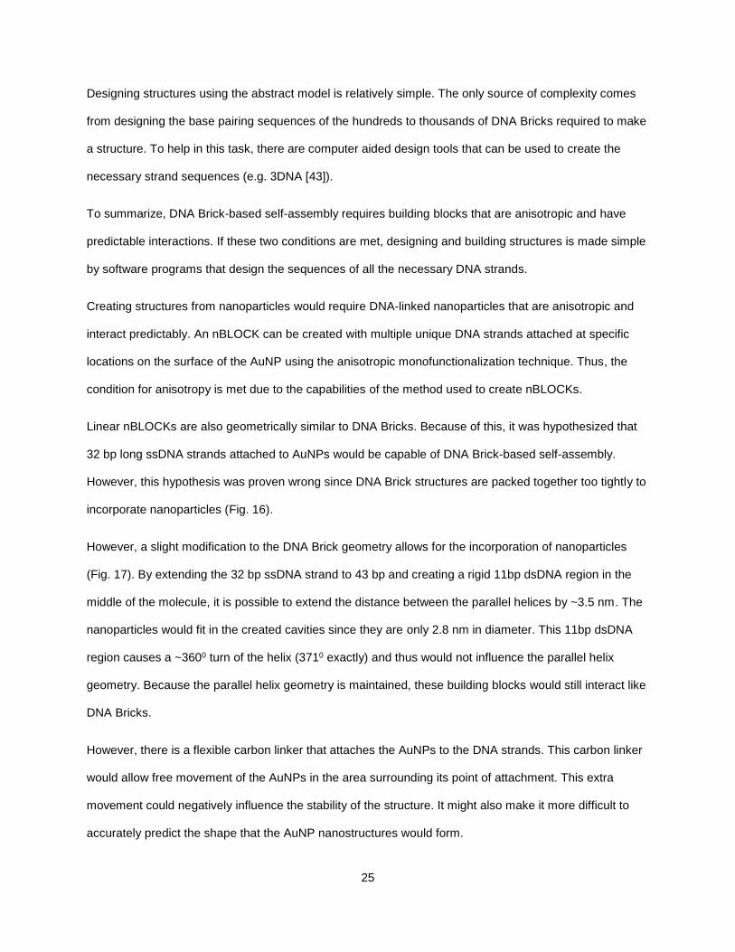
However, there is a flexible carbon linker that attaches the AuNPs to the DNA strands. This carbon linker
would allow free movement of the AuNPs in the area surrounding its point of attachment. This extra
movement could negatively influence the stability of the structure. It might also make it more difficult to
accurately predict the shape that the AuNP nanostructures would form.

26
Figure 17. Modified DNA Bricks with cavity for nanoparticles | The modified Bricks are created by extending a 32 bp long DNA Brick by 11 bp.
The middle 11bp becomes double-stranded and gives some rigidity to the created cavity. The 11bp region causes a ~3600 turn of the helix so that
when the ends of the DNA strand fold, they create a parallel helix geometry nearly identical to that of unmodified DNA Bricks. These modified DNA
Bricks create enough space for a nanoparticle to reside in the center.
27
Figure 18. Different possible geometries of nBLOCKs with one DNA strand attached | The flexible carbon linker binding the AuNP to the
DNA strand allows free movement. Tuning the length of this linker would help stabilize certain geometries.

28
Nevertheless, according to these models, nBLOCKs with 43bp DNA strands attached could be used to
create nanostructures (Fig. 19). There are three assumptions on which this conclusion is based. The first
is that the 3710 turn created by the 11bp dsDNA region does not change the relative orientations of the
parallel helices. According to the caDNAno software used to design DNA origami structures, there is ±
120 of angle forgiveness in helical turns [18,44]. This means that any helical turns between the angles of
3480 and 3720 will have properties nearly identical to those of an exact 3600 turn. The 3710 turn used in
this model is within this zone of forgiveness and thus will create a geometry similar to that of a DNA Brick
without the extra 11bp backbone.
The second assumption is that the AuNPs will occupy the spaces left by the 11bp backbones without any
problems. The carbon linker between the AuNPs and DNA strands is flexible which would allow the
AuNPs to move freely in the vicinity of their attached DNA strand. This freedom of movement would be
emphasized at the boundaries where there are no DNA backbones to provide specific cavities. One way
to overcome this problem at the boundaries is to replace the nBLOCKs with 43 bp ssDNA strands without
any AuNPs attached. The length of the carbon linker could be also changed to give the AuNPs more or
less freedom of movement throughout the rest of the structure. The size and shape of the AuNPs could
also be modified to tune the freedom of movement. The structures’ tolerances to movement of the AuNPs
will be determined by applications of interest.
One final assumption is that the electrostatic repulsion between the AuNPs’ negatively charged capping
ligands and the phosphate backbones of the DNA strands will not prevent structure building. Electrostatic
repulsion could make the structures less stable than DNA Brick structures. To overcome this, it would be
possible to use stronger bonds between the DNA strands by increasing the number of overlapping base
pairs. For example, 19 bp binding domains could be used instead of 8 bp binding domains since they
both cause ~2700 turns of the helix. Additionally, lowering the concentration of capping ligand on the
surface of the particles could decrease the electrostatic repulsion between the AuNPs and DNA strands if
it became a problem. Tuning these variables and creating the optimal conditions for creating structures
using nBLOCKs with one DNA strand attached will be the subject of future experiments.

29
Figure 19. Creation of nanostructures from the inside-out using linear nBLOCKs with one DNA strand attached | By creating strand
sequences that self-assemble in a manner identical to DNA Bricks, it would be possible to create the desired structures from linear nBLOCKs.
30
There is another nBLOCK geometry that could theoretically be used for DNA Brick-based self-assembly.
It is possible to attach two 16 bp ssDNA strands on either side of an AuNP using the anisotropic
monofunctionalization technique. Because the AuNPs are in the middle of two halves of a DNA Brick, it
would be unnecessary to change the DNA Brick geometry to create space for the nanoparticles. The
positions of the nanoparticles would also be better defined since there are two points of attachment to the
DNA structure rather than one. Thus, this geometry of nBLOCK could provide several key benefits for
creating structures compared to nBLOCKs with only one DNA strand attached.
However, having two points of attachment to the DNA Brick also creates a problem. As mentioned
previously, predictable geometry is a key requirement for DNA Brick-based self-assembly. The rigidity of
dsDNA ensured that all of the DNA Bricks became oriented and positioned in specific locations when they
came together. This was possible because rotational movement of one DNA Brick became transferred to
all of its binding partners.
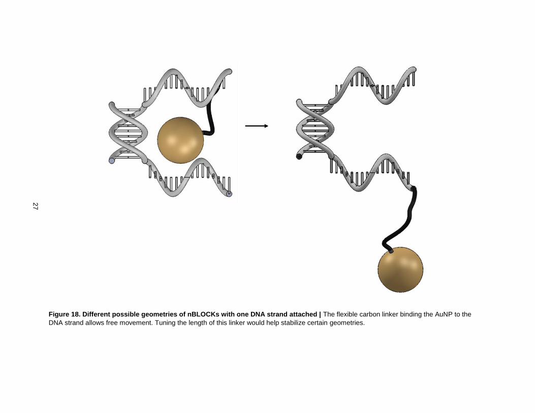
The same cannot be said for nBLOCKs with two DNA strands attached (Fig. 20). The AuNPs are
attached in the middle of the two halves of a DNA Brick through carbon linkers. These linkers are made
up of σ bonds that all allow free, independent rotation of the DNA molecules. Because of this, nBLOCKs
and their binding partners are also free to rotate independently.
An abstract model of these nBLOCKs were created to reflect their differences with DNA Bricks (Fig. 21).
The abstract nBLOCKs have four binding domains like DNA Bricks. However, these binding domains are
smooth rather than rigidly shaped. Additionally, there is no 900 offset between the binding domains since
the added flexibility makes it impossible to control their relative orientations.
A structure consisting of four nBLOCKs was created using this model. Because of the added flexibility,
there is no way to accurately predict the structure that a group of these nBLOCKs will form (Fig. 21C-D).
There would be mixtures of structure-types, each slightly different from the rest. It might be possible to
separate out the correct structures from incorrect ones. However, this separation step would add an
additional level of complexity to building structures.
31
Figure 20. nBLOCKs with two DNA strands attached are not as rigid as dsDNA | When a rotational
force is applied to one end of the structure (green), that rotational movement is not transferred to the
nBLOCKs on the other side (red). This makes it difficult to predict the relative geometries of the
nBLOCKs and their binding partners.

32
Figure 21. Creation of nanostructures from linear nBLOCKs with two DNA strands attached | A. Abstract model of nBLOCK with two DNA
strands attached. Each of the four binding domains are smooth rather than rigid. There is no control over the relative orientation of the building
blocks. B. Linear chain of nBLOCKs. The front of the top red binding domain (black peg) is complementary to the back of the bottom grey binding
domain (black hole). When these binding domains interact, they can drive the formation of two different structures. C. The order of the binding
domains starting from red (R) is RYGB in the counter clockwise direction. D. The same building blocks forming a different structure with the
binding domains ordered RYGB in the clockwise direction.
33
Because of these complications, it would be worthwhile to focus on using nBLOCKs with one DNA strand
attached to create structures. These nBLOCKs form structures more reliably than those with two DNA
strands attached. In fact, these nBLOCKs are extremely promising candidates for self-assembling AuNP
nanostructures from the inside out with precise control over their final size and shape. Nevertheless, it will
be necessary to test the key assumptions using a more detailed modelling software in the future. These
tests will be discussed in the Future Works section.
34
3.2 Improving the Efficiency of the Anisotropic Monofunctionalization Technique
The anisotropic monofunctionalization technique [32] is capable of producing nBLOCKs that are capable
of DNA Brick-based self-assembly. However, recent experiments have shown that the method suffers
from low yield. Thus, improving the method’s efficiency is a key step towards realizing the goal of building
structures from nBLOCKs.
The anisotropic monofunctionalization strategy involves three steps (Fig. 22). The first step is to bind DNA
to a solid support. The solid support spaces out the DNA strands so that when AuNPs bind, only one
DNA strand can bind to each particle. The second step is to bind AuNPs to the thiol groups on the DNA
strands. The third step is to cleave the linkage between the DNA strands and solid support and collect the
nBLOCKs.
The original protocol used an electrostatic interaction between a positively charged amine group bound to
the oligonucleotides and negatively charged carboxyl groups bound to the solid support to carry out the
first step [32]. This strategy resulted in a large amount of nonspecific binding between the DNA strands
and solid support which lowered the yield of the method. Additionally, the DNA strands on the
nanoparticles were still attached to the amine group after the cleavage step (Fig. 22B). There are two
limitations to leaving the amine group attached. The first is that a positively charged molecule could
interfere with the close-packing of DNA strands during DNA Brick-based self-assembly. The second
limitation is that certain downstream molecular biology applications, e.g. polymerase chain reaction or
DNA ligation, require an unmodified DNA end.
Overcoming the limitations of the original protocol would require a new linkage reaction. The
photocleavable (PC) biotin-streptavidin interaction is one potential alternative. Biotin and streptavidin
have an extremely high affinity for one another with a dissociation constant of 4x10-14 M [36]. It is one of
the most specific and reliable reactions currently known. A photocleavable nitrobenzene linker ensures
that the DNA strands are left with an unmodified end after cleavage (Fig. 22C). Based on this information,
it was hypothesized that the PC biotin-streptavidin interaction could be used to overcome the limitations
of the anisotropic monofunctionalization method.

35
Figure 22. The anisotropic monofunctionalization technique | A. The first step of the method involves binding DNA strands to a solid support
through a reversible reaction. The second step is to bind AuNPs to the beads through a thiol linker on the DNA strands. The third step is to reverse
the binding reaction and collect the DNA-linked AuNPs. B. The original protocol left an amine group on attached to the DNA strands. C. A
photocleavage reaction would leave an unmodified end for downstream molecular biology applications.
36
To test this hypothesis, DNA strands with a PC biotin modification were added to streptavidin coated
magnetic beads. The absorbance of the DNA solutions at 260nm were measured before and after binding
and the extinction coefficient provided by the manufacturer was used to calculate the amount of DNA
bound to the beads (Fig. 23). The 25.3 and 22.0 pmols of DNA binding for biotinylated and PC
biotinylated oligonucleotides respectively were slightly higher than the amount predicted by the
manufacturer. However, both values were within a single standard deviation. On the other hand, only 1.7
pmols of the non-biotinylated DNA strands bound to the beads. These results suggested that the PC
biotin-streptavidin interaction is much more specific and reliable than the electrostatic interaction.
The second step of the anisotropic monofunctionalization method is to bind AuNPs to the DNA strands on
the beads. The DNA strands were purchased with a dithiol protecting group on their 3’ ends (Fig. 24).
This protecting group had to be cleaved using a reducing agent, e.g. TCEP, before the DNA could bind to
the AuNPs. It is important to note here that oxygen can convert the free thiols back to dithiols if it is
present (Fig. 24).
After deprotecting the DNA strands, AuNPs were added and the mixture was incubated overnight. After
12 hours of incubation, only 3% of the DNA strands became attached to AuNPs (Fig. 26). Two primary
factors were identified as likely causes of this low efficiency. The first was electrostatic repulsion between
the DNA strands and AuNPs. The AuNPs have a negatively charged capping ligand (MESA) and the
DNA strands have negatively charged phosphate backbones. Electrostatic repulsion between the like-
charges could have prevented the AuNPs from getting close enough to the DNA strands to attach (Fig.
25). The second factor was that the thiol linkages could have reformed into disulfides after reduction due
to the presence of oxygen (Fig. 24)
Numerous experiments were carried out to test these various factors and their influence on the efficiency
of ligand exchange (Fig. 26). It is important to note here that there were not enough repetitions of each
experiment to prove statistical significance. Conditions that improved the yield were accepted and
implemented but the experiments themselves were not repeated so that ligand exchange could be
improved further.

37
Figure 23. DNA binding to streptavidin coated magnetic beads | Concentration decreases were
calculated using the absorbance value at 260 nm and an extinction coefficient provided by the
manufacturer. Theoretical maximum was ~ 20 pmols as provided by the manufacturer of streptavidin-
coated magnetic beads. Biotinylated and PC-Biotinylated DNA strands became bound within one
standard deviation of the theoretical max. Only 1.7 pmols of non-biotinylated DNA strands became
bound. There was a statistically significant difference between biotinylated and bon-biotinylated DNA
strands as well as between PC biotinylated and non-biotinylated DNA strands (indicated by *), but not
between biotinylated and PC biotinylated DNA strands.
1.7
25.3
22.8
0.0
5.0
10.0
15.0
20.0
25.0
30.0
Non-Biotinylated Biotinylated PC Biotinylated
DN
A B
ou
nd
(pm
ols
)DNA Binding to Beads
Theoretical Max
*
38
Figure 24. TCEP reduction of protected oligonucleotides (modified from [43]) | Oligonucleotides were purchased with a disulfide protecting
group. This group must be removed in order to bind the oligonucleotides to the AuNPs. TCEP, a reducing agent, was used to carry out this
reaction. The disulfide bond can reform if oxygen is present.

39
Figure 25. Preparing AuNPs and binding DNA | AuNPs are prepared with a DMAP capping ligand (Top). MESA molecules bind to the AuNPs
through covalent thiol bonds and thus replace the weaker DMAP molecules. The DMAP-MESA AuNPs are added to the DNA-bound beads. They
attach through a similar ligand exchange reaction involving DMAP molecules and covalent thiol bonds. Negative charges from the MESA capping
ligands (red circles) and phosphate backbone (blue circles) could potentially repel each other (bottom right).
40
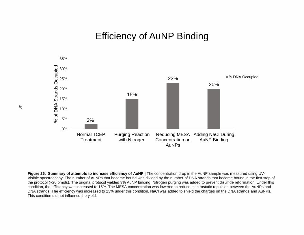
Figure 26. Summary of attempts to increase efficiency of AuNP | The concentration drop in the AuNP sample was measured using UV-Visible spectroscopy. The number of AuNPs that became bound was divided by the number of DNA strands that became bound in the first step of the protocol (~20 pmols). The original protocol yielded 3% AuNP binding. Nitrogen purging was added to prevent disulfide reformation. Under this condition, the efficiency was increased to 15%. The MESA concentration was lowered to reduce electrostatic repulsion between the AuNPs and DNA strands. The efficiency was increased to 23% under this condition. NaCl was added to shield the charges on the DNA strands and AuNPs. This condition did not influence the yield.
3%
15%
23%
20%
0%
5%
10%
15%
20%
25%
30%
35%
Normal TCEPTreatment
Purging Reactionwith Nitrogen
Reducing MESAConcentration on
AuNPs
Adding NaCl DuringAuNP Binding
% o
f D
NA
Str
an
ds O
ccu
pie
d
Efficiency of AuNP Binding
% DNA Occupied
41
The first step was to purge the buffers with N2 to reduce the amount of O2 present and thus reduce the
amount of disulfide reformation. This condition improved the efficiency to 15% so N2 purging was
implemented during follow-up experiments. The next step was to reduce the concentration of the
negatively charged MESA capping ligand to reduce electrostatic repulsion between the AuNPs and DNA
strands. The MESA concentration was reduced until a minimum concentration was reached (3x lower
than original protocol), below which the AuNPs became unstable due to uncontrolled aggregation. This
condition improved the efficiency of AuNP binding to 23%. It was hypothesized that the counter ions in
NaCl solution could be used to shield the electrostatic repulsion further. However, adding NaCl did not
improve the efficiency of AuNP binding.
These results together suggested that both electrostatic repulsion and disulfide reformation could have
affected the efficiency of AuNP binding. However, the maximum yield of 25% suggested that there are
other variables that have not been considered. Since lowering the MESA concentration slightly improved
the yield while adding NaCl to shield the charge repulsion did not, it is possible that the increased yield
was caused by something other than reduced electrostatic repulsion. MESA binds to the surface of the
AuNPs through a thiol interaction which replaces some of the DMAP molecules (Fig. 25). This reaction is
identical to the ligand exchange reaction that takes place when DNA strands bind to the AuNPs. Thus, it
is possible that the MESA molecules themselves prevented the DNA strands from binding to the AuNPs
via steric hindrance. To test this, NaCl was added to reactions involving AuNPs with the original amount
of MESA (3x more). The efficiency of AuNP binding was 12% (data not shown). This result suggested
that MESA itself is the cause of low ligand exchange efficiency and not electrostatic repulsion. Testing
this hypothesis further will be the subject of future experiments.
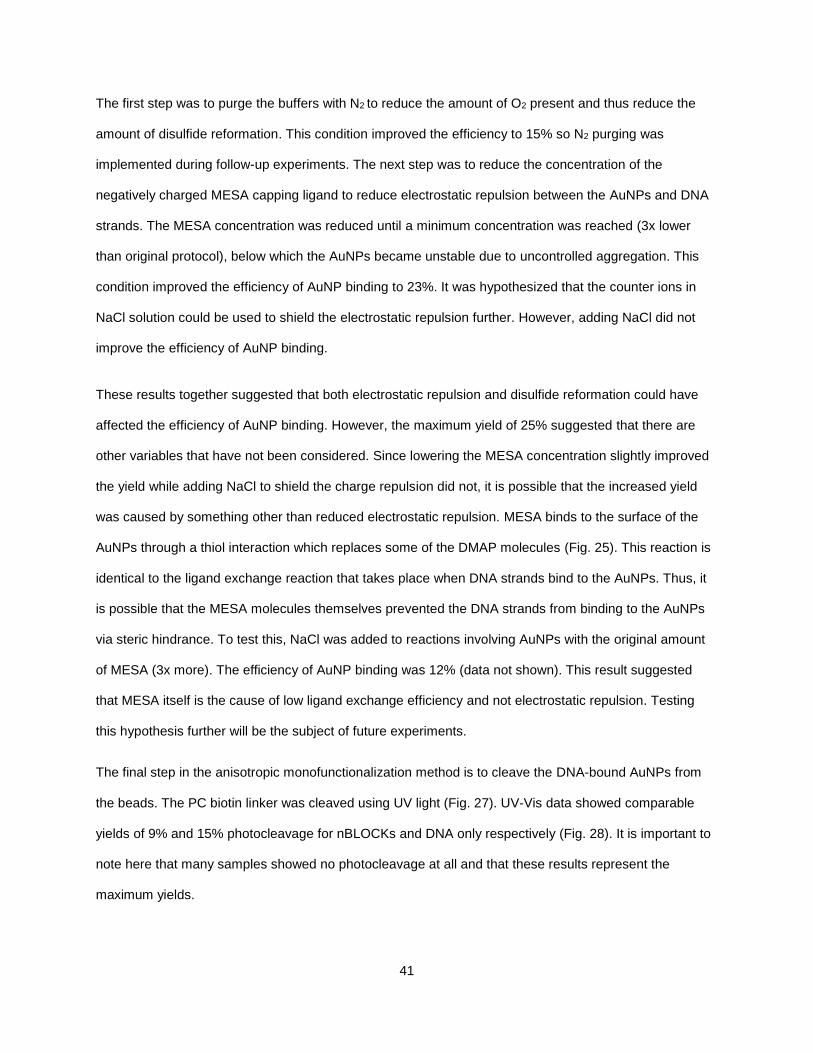
The final step in the anisotropic monofunctionalization method is to cleave the DNA-bound AuNPs from
the beads. The PC biotin linker was cleaved using UV light (Fig. 27). UV-Vis data showed comparable
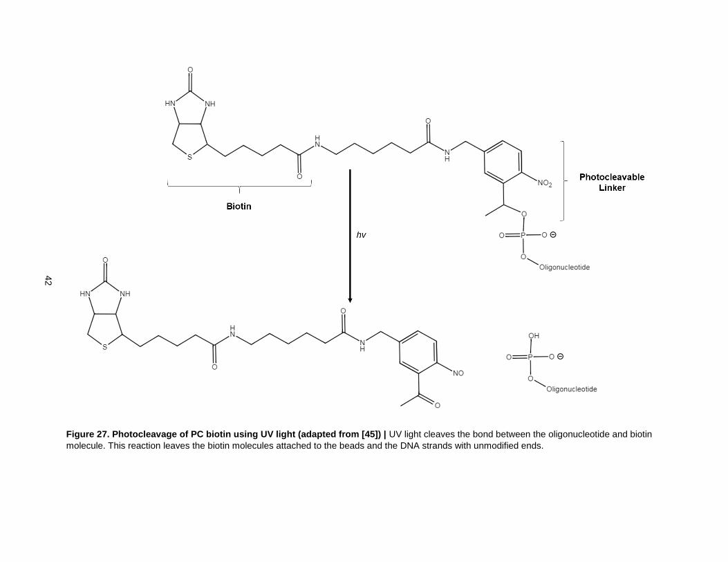
yields of 9% and 15% photocleavage for nBLOCKs and DNA only respectively (Fig. 28). It is important to
note here that many samples showed no photocleavage at all and that these results represent the
maximum yields.
42
Figure 27. Photocleavage of PC biotin using UV light (adapted from [45]) | UV light cleaves the bond between the oligonucleotide and biotin
molecule. This reaction leaves the biotin molecules attached to the beads and the DNA strands with unmodified ends.
43
Figure 28. Efficiency of Photocleavage in H2O | Photocleavage was carried out on DNA only and on
DNA-bound AuNPs. The efficiency was determined by calculating the concentration of DNA or nBLOCKs
released into solution and dividing them by the number of DNA strands or AuNPs that became bound
during previous steps. The overall yields of both were similar at around ~10-15% efficiency.
15%
9%
0%
5%
10%
15%
20%
25%
30%
H2O
Eff
icie
ncy o
f P
ho
tocle
ava
ge
Efficiency of Photocleavage
DNA nBLOCKs

44
It was hypothesized that the efficiency of photocleavage was influenced by the buffer conditions of the
photocleavage reaction. In buffer, ssDNA takes on a more linear form whereas in water, it is much more
agglomerated. If the DNA strands agglomerated around the photocleavable linkers in water, it is possible
that they prevented the UV light from reaching the nitrobenzene ring. To test this hypothesis,
photocleavage was carried out in 10 mM Tris HCl buffer. The efficiency of photocleavage improved to
60% photocleavage for DNA only (Fig. 29). However, this improvement has not yet been replicated for
nBLOCKs. Tuning the buffer condition will be the subject of future experiments.
To summarize, the PC biotin – streptavidin interaction can be used to overcome the limitations of the
previous nBLOCK protocol. The first step of the reaction was carried out with maximum efficiency and
specificity. Additionally, the nBLOCKs created using this method had unmodified DNA strands attached.
This unmodified DNA strand is key for downstream molecular biology techniques and is also theoretically
important for the close packing of nBLOCKs during DNA Brick-based self-assembly. Thus, some of the
limitations of the previous nBLOCK protocol have been successfully overcome.
Nevertheless, the overall efficiency of the reaction is still low (25% [Step 2] x 9% [Step 3] ≈ 2% total yield).
Several attempts were made to improve the efficiency of the second step but the maximum efficiency
achieved was around 25%. The efficiency of the photocleavage step peaked at around 10% yield for
nBLOCKs, though the yield was improved to 60% for DNA only. Further improving the yields of these two
steps will be the focus of future experiments.
One way to improve the yield of the second step would be to change the capping ligand on the AuNPs to
something weaker than MESA. Bis(p-sulfonatophenyl)phenylphosphine dihydrate dipotassium (BSPP)
has been used to cap AuNPs for similar ligand exchange reactions. These AuNPs bound to DNA strands
with much higher efficiency than DMAP-MESA AuNPs [36]. It might also be possible to use a disulfide
functional group to bind the DNA strands to the AuNPs since it forms a stronger bond than the thiol
linkage. The combination of these two changes would likely significantly improve the yield of AuNP
binding. The efficiency of the third step could be improved by tuning the buffer conditions during
photocleavage.

45
Figure 29. Efficiency of Photocleavage in Buffer | It was hypothesized that the efficiency of
photocleavage could be improved by changing the reaction solution from water to buffer. Doing so raised
the efficiency of photocleavage to 60% for DNA only. Tuning the buffer during photocleavage of
nBLOCKs will be the subject of future experiments.
60%
15%
0%
10%
20%
30%
40%
50%
60%
70%
10mM Tris HCl H2O
Eff
icie
ncy o
f P
ho
tocle
ava
ge
Efficiency of Photocleavage
DNA
46
4. Conclusion
The goal of this project was to create nanostructures from the inside out using linear nBLOCKs. While this
goal was not fully accomplished, several steps were taken towards realizing it.
Computer modelling revealed that anisotropy and predictable geometry were key components of DNA
Brick-based self-assembly. This information was used to design linear nBLOCKs that are capable of DNA
Brick-based self-assembly. These nBLOCKs consist of an AuNP attached to a single 43 bp long DNA
Brick. The DNA Brick geometry was modified by adding an additional 11bp backbone region to create
space for AuNPs. One key assumption for these building blocks was that the 3710 turn created by the
11bp region would not significantly influence the parallel helix geometry of the DNA strands. This
assumption was based on previous experimental validations of modelled DNA origami structures [18,44].
Additionally, it was assumed that the freely floating nanoparticles would populate specific cavities created
by the dsDNA backbones. However, the AuNPs are free to move because they are attached to the DNA
structure through flexible carbon linkers. There are several variables that can be tuned to increase or
decrease the freedom of movement depending on the desired applications. Nevertheless, the modelling
results showed that it would be possible to create nanostructures from the inside out using linear
nBLOCKs.
Additionally, the modelling results revealed that it would be difficult to create structures using nBLOCKs
with two DNA strands attached. The free, independent rotation of the DNA strands on either side of the
particle make it difficult to create structures with specific geometries. Future efforts should be focused on
using nBLOCKs with a single DNA strand attached to build structures.
The experimental work itself showed that the photocleavable biotin – streptavidin interaction can be used
to improve the capabilities of the anisotropic monofunctionalization method. This new method was
successfully used to create and recover nBLOCKs. However, the maximum overall yield was only 2%.
The major limitation at this stage is the inefficiencies of AuNP binding and photocleavage. The yields
have not yet reached the level necessary for structure building. Overcoming these roadblocks will
eventually allow for the creation of nanostructures from linear nBLOCKs.
47
5. Future Work
Solidworks models are inherently limited because they can only simulate rigid objects. In reality, ssDNA is
very flexible. Additionally, the strength of binding between DNA strands is dependent on such variables
as temperature and salt concentration. Neither of these variables can be incorporated into the Solidworks
models.
The Solidworks models showed that nBLOCKs with a single DNA strand are capable of DNA Brick-based
self-assembly. Nevertheless, it is possible that the addition of an 11bp dsDNA backbone and the free
floating AuNPs would negatively influence the structures’ stability in a way that the Solidworks models
could not predict. The structures’ stability will also be influenced by the size and shape of the AuNPs, the
length of the carbon linker attaching the AuNPs to the DNA strands, the concentration of the AuNPs’
capping ligand and the strength of binding between building blocks (e.g. the length of overlapping
complementary regions).
Simulating these variables will require a more powerful modelling program. The OxDNA molecular
dynamics simulator is capable of simulating both DNA and nBLOCKs [33]. The program was recently
limited by the time required to simulate large numbers of nBLOCKs but this limitation has since been
overcome. Thus, it is likely that this model would help fill in knowledge gaps left by the Solidworks
models. A set of strand sequences that can be used to study the self-assembly of nBLOCKs in OxDNA is
given in Appendix A.
The Solidworks models themselves could also be used to design dynamic structure changes involving
strand displacement reactions. This has not yet been tried for either DNA Brick or AuNP-based structures
but would likely improve their versatility for specific applications.
Successfully implementing the modelling results will require improving the efficiency of the anisotropic
monofunctionalization method as well. Based on the results of this thesis, there are three options to
further improve the efficiency of the protocol. The first is to change the AuNP capping ligand. One
capping ligand that binds more weakly than MESA and has been successfully used for a similar ligand
exchange reaction is bis(p-sulfonatophenyl)phenylphosphine dihydrate dipotassium (BSPP) [36]. The
48
second option is to use a disulfide modified oligonucleotide instead of a thiol modified DNA strand. The
dithiol moiety would allow the DNA strands to bind more tightly to the particles and push the equilibrium of
the reaction further towards AuNP binding. The third option is to optimize the buffer conditions and
maximize the efficiency of photocleavage. The combination of these three conditions will likely provide the
best results.

49
6. References
[1]H. Yockell-Lelièvre, F. Lussier and J. Masson, "Influence of the Particle Shape and Density of Self-
Assembled Gold Nanoparticle Sensors on LSPR and SERS", The Journal of Physical Chemistry C, vol.
119, no. 51, pp. 28577-28585, 2015.
[2]H. Chen, X. Kou, Z. Yang, W. Ni and J. Wang, "Shape- and Size-Dependent Refractive Index
Sensitivity of Gold Nanoparticles", Langmuir, vol. 24, no. 10, pp. 5233-5237, 2008.
[3]A. Abbas, R. Kattumenu, L. Tian and S. Singamaneni, "Molecular Linker-Mediated Self-Assembly of
Gold Nanoparticles: Understanding and Controlling the Dynamics", Langmuir, vol. 29, no. 1, pp. 56-64,
2013.
[4]S. Sinha, D. Paul, R. Kanchanapally, A. Pramanik, S. Chavva, B. Viraka Nellore, S. Jones and P. Ray,
"Long-range two-photon scattering spectroscopy ruler for screening prostate cancer cells", Chem. Sci.,
vol. 6, no. 4, pp. 2411-2418, 2015.
[5]J.-W. Kim, H. Moon, M. Benamara, J. Sakon, G. Salamo and V. Zharov, "Aqueous-phase synthesis of
monodisperse plasmonic gold nanocrystals using shortened single-walled carbon nanotubes", Chemical
Communications, vol. 46, no. 38, p. 7142, 2010.
[6]P. Jain and M. El-Sayed, "Plasmonic coupling in noble metal nanostructures", Chemical Physics
Letters, vol. 487, no. 4-6, pp. 153-164, 2010.
[7]E. Galanzha, J.-W. Kim and V. Zharov, "Nanotechnology-based molecular photoacoustic and
photothermal flow cytometry platform forin-vivodetection and killing of circulating cancer stem cells",
Journal of Biophotonics, vol. 2, no. 12, pp. 725-735, 2009.
[8]E. Galanzha, E. Shashkov, T. Kelly, J.-W. Kim, L. Yang and V. Zharov, "In vivo magnetic enrichment
and multiplex photoacoustic detection of circulating tumour cells", Nature Nanotechnology, vol. 4, no. 12,
pp. 855-860, 2009.
[9] J.-W. Kim, E. Galanzha, E. Shashkov, H. Moon and V. Zharov, "Golden carbon nanotubes as
multimodal photoacoustic and photothermal high-contrast molecular agents", Nature Nanotechnology,
vol. 4, no. 10, pp. 688-694, 2009.
[10]E. Galanzha, M. Kokoska, E. Shashkov, J.-W. Kim, V. Tuchin and V. Zharov, "In vivofiber-based
multicolor photoacoustic detection and photothermal purging of metastasis in sentinel lymph nodes
targeted by nanoparticles", Journal of Biophotonics, vol. 2, no. 8-9, pp. 528-539, 2009.
[11]N. Abadeer and C. Murphy, "Recent Progress in Cancer Thermal Therapy Using Gold Nanoparticles",
The Journal of Physical Chemistry C, vol. 120, no. 9, pp. 4691-4716, 2016.
[12]G. Yang and D. Hallinan, "Gold Nanoparticle Monolayers from Sequential Interfacial Ligand Exchange
and Migration in a Three-Phase System", Scientific Reports, vol. 6, no. 1, 2016.
[13]S. Sun, P. Mendes, K. Critchley, S. Diegoli, M. Hanwell, S. Evans, G. Leggett, J. Preece and T.
Richardson, "Fabrication of Gold Micro- and Nanostructures by Photolithographic Exposure of Thiol-
Stabilized Gold Nanoparticles", Nano Letters, vol. 6, no. 3, pp. 345-350, 2006.
[14]N. Seeman, "An Overview of Structural DNA Nanotechnology", Molecular Biotechnology, vol. 37, no.
3, pp. 246-257, 2007.
[15]G. Manning, "The Persistence Length of DNA Is Reached from the Persistence Length of Its Null
Isomer through an Internal Electrostatic Stretching Force", Biophysical Journal, vol. 91, no. 10, pp. 3607-
3616, 2006.
50
[16]P. Rothemund, "Folding DNA to create nanoscale shapes and patterns", Nature, vol. 440, no. 7082,
pp. 297-302, 2006.
[17]D. Han, S. Pal, J. Nangreave, Z. Deng, Y. Liu and H. Yan, "DNA Origami with Complex Curvatures in
Three-Dimensional Space", Science, vol. 332, no. 6027, pp. 342-346, 2011.
[18]C. Castro, F. Kilchherr, D. Kim, E. Shiao, T. Wauer, P. Wortmann, M. Bathe and H. Dietz, "A primer to
scaffolded DNA origami", Nature Methods, vol. 8, no. 3, pp. 221-229, 2011.
[19]E. Andersen, M. Dong, M. Nielsen, K. Jahn, R. Subramani, W. Mamdouh, M. Golas, B. Sander, H.
Stark, C. Oliveira, J. Pedersen, V. Birkedal, F. Besenbacher, K. Gothelf and J. Kjems, "Self-assembly of a
nanoscale DNA box with a controllable lid", Nature, vol. 459, no. 7243, pp. 73-76, 2009.
[20]A. Marchi, I. Saaem, B. Vogen, S. Brown and T. LaBean, "Toward Larger DNA Origami", Nano
Letters, vol. 14, no. 10, pp. 5740-5747, 2014.
[21] D. Zhang and G. Seelig, "Dynamic DNA nanotechnology using strand-displacement reactions",
Nature Chemistry, vol. 3, no. 2, pp. 103-113, 2011.
[22]J. Zheng, J. Birktoft, Y. Chen, T. Wang, R. Sha, P. Constantinou, S. Ginell, C. Mao and N. Seeman,
"From molecular to macroscopic via the rational design of a self-assembled 3D DNA crystal", Nature, vol.
461, no. 7260, pp. 74-77, 2009.
[23]Y. Ke, L. Ong, W. Shih and P. Yin, "Three-Dimensional Structures Self-Assembled from DNA Bricks",
Science, vol. 338, no. 6111, pp. 1177-1183, 2012.
[24]Y. Ke, L. Ong, W. Sun, J. Song, M. Dong, W. Shih and P. Yin, "DNA brick crystals with prescribed
depths", Nature Chemistry, vol. 6, no. 11, pp. 994-1002, 2014.
[25]M. Patitz, "An introduction to tile-based self-assembly and a survey of recent results", Natural
Computing, vol. 13, no. 2, pp. 195-224, 2013.
[26]D. Doty, "Theory of algorithmic self-assembly", Communications of the ACM, vol. 55, no. 12, p. 78,
2012.
[27]B. Ding, H. Wu, W. Xu, Z. Zhao, Y. Liu, H. Yu and H. Yan, "Interconnecting Gold Islands with DNA
Origami Nanotubes", Nano Letters, vol. 10, no. 12, pp. 5065-5069, 2010.
[28]W. Liu, M. Tagawa, H. Xin, T. Wang, H. Emamy, H. Li, K. Yager, F. Starr, A. Tkachenko and O. Gang,
"Diamond family of nanoparticle superlattices", Science, vol. 351, no. 6273, pp. 582-586, 2016.
[29]A. Kuzyk, R. Schreiber, Z. Fan, G. Pardatscher, E. Roller, A. Högele, F. Simmel, A. Govorov and T.
Liedl, "DNA-based self-assembly of chiral plasmonic nanostructures with tailored optical response",
Nature, vol. 483, no. 7389, pp. 311-314, 2012.
[30]S. Park, A. Lytton-Jean, B. Lee, S. Weigand, G. Schatz and C. Mirkin, "DNA-programmable
nanoparticle crystallization", Nature, vol. 451, no. 7178, pp. 553-556, 2008.
[31]D. Nykypanchuk, M. Maye, D. van der Lelie and O. Gang, "DNA-guided crystallization of colloidal
nanoparticles", Nature, vol. 451, no. 7178, pp. 549-552, 2008.
[32] J.-W. Kim, J.-H. Kim and R. Deaton, "DNA-Linked Nanoparticle Building Blocks for Programmable
Matter", Angewandte Chemie, vol. 123, no. 39, pp. 9351-9356, 2011
[33]C. Armistead, J. Hendricks, T. Fochtman, J. Batta-Mpouma, M. Patitz, R. Deaton and J. Kim,
"Coarse-Grained Simulation of DNA-Linked Nanoparticle Building Blocks", IEEE Conference
Proceedings, 2015.
51
[34] J.-W. Kim and J.-H. Kim, "Sequential Solid-Phase Fabrication of Bifunctional Anchors on Gold
Nanoparticles for Controllable and Scalable Nanoscale Structure Assembly", Langmuir, vol. 24, no. 11,
pp. 5667-5671, 2008.
[35]X. Liu, M. Atwater, J. Wang and Q. Huo, "Extinction coefficient of gold nanoparticles with different
sizes and different capping ligands", Colloids and Surfaces B: Biointerfaces, vol. 58, no. 1, pp. 3-7, 2007.
[36]X. Ma, J. Huh, W. Park, L. Lee, Y. Kwon and S. Sim, "Gold nanocrystals with DNA-directed
morphologies", Nature Communications, vol. 7, p. 12873, 2016.
[37] S. Douglas, H. Dietz, T. Liedl, B. Högberg, F. Graf and W. Shih, "Self-assembly of DNA into
nanoscale three-dimensional shapes", Nature, vol. 459, no. 7250, pp. 1154-1154, 2009.
[38] A. Kuzyk, R. Schreiber, Z. Fan, G. Pardatscher, E. Roller, A. Högele, F. Simmel, A. Govorov and T.
Liedl, "DNA-based self-assembly of chiral plasmonic nanostructures with tailored optical
response", Nature, vol. 483, no. 7389, pp. 311-314, 2012.
[39] Y. Ke, L. Ong, W. Sun, J. Song, M. Dong, W. Shih and P. Yin, "DNA brick crystals with prescribed
depths", Nature Chemistry, vol. 6, no. 11, pp. 994-1002, 2014.
[40] P. Cigler, A. Lytton-Jean, D. Anderson, M. Finn and S. Park, "DNA-controlled assembly of a NaTl
lattice structure from gold nanoparticles and protein nanoparticles", Nature Materials, vol. 9, no. 11, pp.
918-922, 2010.
[41] J.-W. Kim, R Deaton, and J.-H. Kim. “DNA-linked nanoparticle building blocks for nanostructure
assembly and methods of producing the same”, US patent No 9,371,354 (June 21, 2016).
[42] W. Haiss, N. Thanh, J. Aveyard and D. Fernig, "Determination of Size and Concentration of Gold
Nanoparticles from UV−Vis Spectra", Analytical Chemistry, vol. 79, no. 11, pp. 4215-4221, 2007.
[43] S. Gupta, F. Joshi, D. Limbachiya and M. Gupta, “3DNA : A Tool for DNA Sculpting”, FNANO 14
Conference 2014, Snowbird, Utah, USA, 2014.
[43] "Thiol-modified oligonucleotides", Atdbio.com, 2017. [Online]. Available:
http://www.atdbio.com/content/50/Thiol-modified-oligonucleotides. [Accessed: 19- Jul- 2017].
[44] D. Kim, F. Kilchherr, H. Dietz and M. Bathe, "Quantitative prediction of 3D solution shape and
flexibility of nucleic acid nanostructures", Nucleic Acids Research, vol. 40, no. 7, pp. 2862-2868, 2011.
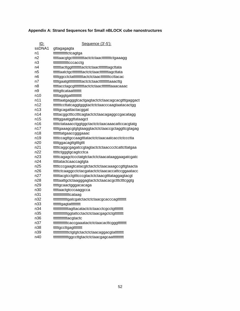
52
Appendix A: Strand Sequences for Small nBLOCK cube nanostructures
ID: Sequence (3'-5'):
ssDNA1 gttagagagta
n1 tttttttttttttctcagtga
n2 tttttaacgtgctttttttttttactctctaacttttttttctgaaagg
n3 ttttttttttttttcccacctg
n4 tttttttacttggtttttttttactctctaacttttttttagcttata
n5 ttttttaatctgctttttttttactctctaacttttttttagcttata
n6 tttttggcctctatttttttttactctctaacttttttttccttacac
n7 tttttgaatgttttttttttttactctctaactttttttttaaacttg
n8 tttttacctagcgtttttttttactctctaacttttttttaaacaaac
n9 tttttgttcataatttttttt
n10 tttttaggtgatttttttttt
n11 ttttttaatgagggtcactgagtactctctaacagcacgtttgaggact
n12 tttttttccttatcaggtgggtactctctaacccaagtaatacactgg
n13 tttttgcagattactacggat
n14 tttttacggctttcctttcagtactctctaacagaggccgacatagg
n15 tttttggaatggttataagct
n16 tttttctataaacctggtggctactctctaacaaacattccacgtatg
n17 tttttgaaagcgtgtgtaaggtactctctaaccgctaggttcgtagag
n18 tttttttatgaaccgggaaac
n19 tttttccagttgccaagtttatactctctaacaatcacctctccctta
n20 tttttggacagttgtttgttt
n21 tttttcaggcgagatccgtagtactctctaacccctcattcttatgaa
n22 tttttctgggtgcagtcctca
n23 tttttcagagctccctatgtctactctctaacataaggaagatcgatc
n24 tttttatactcaaccagtgta
n25 tttttcccgaagtcatacgtctactctctaacaaagccgttgtaacta
n26 tttttctcaaggcctctacgatactctctaacaccattccggaatacc
n27 ttttttacgtcctgtttcccgtactctctaacgtttataggagtacgt
n28 tttttaattgctctaagggagtactctctaacacgctttctttcggtg
n29 tttttgcaactgggacacaga
n30 tttttaactgtcccaaggcca
n31 tttttttttttttttcataag
n32 tttttttttttttgatcgatctactctctaacgcacccagtttttttt
n33 tttttttgagtattttttttt
n34 ttttttttttttttagttacatactctctaacctcgcctgtttttttt
n35 tttttttttttttggtattcctactctctaacgagctctgtttttttt
n36 tttttttttttttacgtactc
n37 tttttttttttttcaccgaaatactctctaacacttcgggtttttttt
n38 tttttgccttgagtttttttt
n39 ttttttttttttttctgtgtctactctctaacaggacgtatttttttt
n40 ttttttttttttttggccttgtactctctaacgagcaatttttttttt