Embed Size (px)
Citation preview

Catalog 8092/USALinear Servo Motor Driven High Speed Precision
www.parkermotion.com Parker Hannifin CorporationElectromechanical Automation Division
Irwin, Pennsylvania
A1
A3
A5
A7
A9
A11
A13
A14
A15
A16
A17
A18
A19
A20
A21
A22
A23
A23
A27
A27
High Speed Precision Systems
Linear Servo Motor Solutions
About Linear Motor Tables...400LXR Series Features
Cable Management Options
Digital Drive Options
Cooling Options
Cleanroom Preparation
404LXR Dimensions
404LXR How to Order
406LXR Dimensions
406LXR How to Order
412LXR (12 Pole) Dimensions
412LXR (12 Pole) How to Order
412LXR (24 Pole) Dimensions
412LXR (24 Pole) How to Order
Dual Carriage TablesDXL Series
Rotary Servo Motor TablesDM1004 Series
Contents(click on desired subject)

Catalog 8092/USALinear Servo Motor Driven High Speed Precision
www.parkermotion.com Parker Hannifin CorporationElectromechanical Automation Division
Irwin, Pennsylvania
Linear Servo Motors Linear Motor Tables• Sizing and selection software
• CAD drawings – download from web
• CD with complete product informationincluding FAQs
• Factory application engineers
• Regional field engineers
• Local automation technology centers
• Complete product testingand documentation
Application Tools and Support• Complete size range
• Fastest response and settling time
• Single-row slotless design ordouble row ironless
• Lower cost and weight(compared to ironless design)
• Excellent heat dissipation
• Custom cables, connectors,windings, etc. for specialrequirements
• Pre-engineered “plug and play” module
• Certified accuracy and repeatability
• Slotless or Iron Core linear motor drives
• Velocity to 4.5 m/sec.
• Acceleration to 5 Gs
• Encoder resolution to 0.1 microns
• Long life cable management system
• Proven protective strip seal
• Quick delivery
Parker Linear Motor Solutions
SystemsMachine builders and OEMs often choose to integratea complete electromechanical system into the machine.They have confidence in knowing that our knowledge,experience, and support will ensure that theirautomation goals are met.
• Minimal design engineering• Ensured component compatibility• Single source supply
SubsystemsOur mechanical subsystems are often utilized by OEMsand Integrators who want a completely assembled multi-axis unit ready for direct hookup to an existing or a newParker motor/drive/control system.
• Reduced engineering effort• Straightforward integration• Modular compatibility
Linear Motor Solutions at “Selectable Levels of Integration”
Component ProductsIf you have the capability and experience to developyour own systems, our broad range of innovative,easy-to-use products will help you get the job done.
• Short leadtime• Large selection• Proven reliability
A3
™

Catalog 8092/USALinear Servo Motor Driven High Speed Precision
www.parkermotion.com Parker Hannifin CorporationElectromechanical Automation Division
Irwin, Pennsylvania
Digital Servo Drives Modular Linear Motor Systems Custom Engineered Systems• Optimized parameters
for linear motors
• Pre-configured motor filesfor easy setup
• Sinusoidal commutation withencoder feedback
• Connectorized cabling foreasy hookup
• Drive/controller models fordirect motion programmingand storage
• Cost-effective multi-axis systems easilydeveloped from standard 400LXRmodules
• Multi-axis cable management
• Seamless integration with other Parkermotion components including ballscrewtables and actuators
• Selectable Levels of Integration
• Single or multi-axis solutionsdesigned “from the ground up”to precisely meet customerrequirements
• Systematic process to convertinitial concepts into final solutionsin the shortest time
• Total system reliability
• CAD generated approval drawings
• Special testing and certificationof final performance andspecifications
A4
™

Catalog 8092/USALinear Servo Motor Driven High Speed Precision
www.parkermotion.com Parker Hannifin CorporationElectromechanical Automation Division
Irwin, Pennsylvania
High speeds
High stiffness
Low maintenance
High precision
Zero backlash
Fast settling time
4 5
7
4. Magnet Rail
Single rail of high en-ergy rare earth mag-nets offers lowerweight and lowercost than doublemagnet type.
1. “Pass-Through” CablingPre-wired, plug-inconnection of themoving payload foreasy hookup ofuser instrumentsor end effectors.
3. High StrengthAluminum BodyExtruded aluminumhousing is precisionmachined to provideoutstanding straight-ness and flatness.
The idea is simple enough. Take a conventional rotaryservo motor and unwrap it. What was the stator is now aforcer and the rotor becomes a magnet bar. With thisdesign, the motor is connected directly to the load. Linearmotion is achieved without any rotary to linear transmis-sion. The forcer is a set of windings that conducts cur-rent, while the stator is a linear path of rare earth magnetsmounted in alternating polarity. Commutation is electron-ic, either with hall effect sensors or sinusoidal drives.
About Linear Motors...
2. Connector Panel
Electrically shieldedpanel provides “plug-in”connectivity andquick disconnectfor all signal andpower requirements.
2 3
1
The brushless linear servo motor offers the speedof a belt drive with the precision of a ground ballscrewdrive. With only two primary elements, it is considerablyless complicated than the ballscrew which has more thana dozen components in the drive train. The result is aresponse rate that can be 10 times faster, translating intoquicker acceleration and settling times for higher through-put. There are three main types of brushless linear motors:iron core, ironless, and slotless. Each offers certain per-formance advantages. The slotless design exhibits thebest combination of attributes for the majority of applica-tions. These include good linear force, smooth transla-tion, thermal stability and low cost. The iron core designprovides significantly higher continuous and peak thruststo handle applications involving heavy payloads with highacceleration.
A5

Catalog 8092/USALinear Servo Motor Driven High Speed Precision
www.parkermotion.com Parker Hannifin CorporationElectromechanical Automation Division
Irwin, Pennsylvania
8 109
6
5. Slotless or Iron CoreLinear Motor
Provides a highly respon-sive, zero backlash drivesystem. Both motors of-fer excellent heat man-agement, durability,andhave built-in thermal sen-sor and hall sensors.
6. LinearGuidance System
The highly engineeredcarriage and bearingsystem effectivelycounters the combinedproblematic effects ofheat,high speed andhigh acceleration.
7. Integral LinearEncoderProtected non-contactfeedback with selectableresolutions to 0.1 micron.Z channel is factoryaligned to home sensorfor precise homing.
8. Limit/Home Sensors
Proximity sensorsestablish end oftravel and “home”location and are easilyadjustable over entirelength to restrict thetravel envelope.
9. “Quick Change” CablingInnovative CableTransport Module offersextended life (30 millioncycles) and a simplecable changing systemfor preventativemaintenance.
Protective Seals
Hard Shell aluminumcover combined withstainless steel stripseals provide IP30protection to interiorcomponents as wellas enhance overallappearance.
Linear motors cannot function on their own. Before motioncan occur, a platform must be engineered to provide sup-port, direction, and feedback for the linear motor. Bearings,cables, connectors, encoder, travel stops, homing sensorand other components must be performance matched andintegrated to achieve desired motion and control.
Parker linear motor tables provide all this and more in apre-engineered, easily mounted, ready to run package. Thelinear motor magnet rail is mounted to a stationary base andthe forcer is mounted to the moveable carriage. The onlycontact between the moving carriage and the stationary baseis through the linear support bearings. High precision squarerail bearings provide load support, low-friction translation,and a precise linear path. A high resolution linear encoderprovides the required velocity and positional information tothe motor controller, and a unique cable management sys-tem enables high performance motion with a life of 30 mil-lion inches and beyond. Parker tables, with the slotless lin-ear motor, are offered in three sizes (404LXR, 406LXR,412LXR). The largest (412LXR) is also available with aniron core linear motor for heavy duty, high performance ap-plications.
About Linear Motor Tables...
10.
Pre-engineered package
Performance matched components
Protection from environment
Certified precision
A6
Catalog 8092/USALinear Servo Motor Driven High Speed Precision
www.parkermotion.com Parker Hannifin CorporationElectromechanical Automation Division
Irwin, Pennsylvania
400LXR Series Linear Motor Tables
FeaturesVelocity to 4.5 m/sec
Acceleration to 5 Gs
Encoder resolution to 0.1 micron
Cleanroom compatible
Easy multi-axis mounting
Cable management system
Proven strip seal
Performance Matched Components
The 400LXR Series linear servo motor tablesachieve optimum performance by combining slotless orironcore motor technology with performance matchedmechanical elements and feedback devices. Fastresponse, high acceleration, smooth translation,high velocity, and quick settling time describe theperformance characteristics found in the 400LXRwhile high repeatability, precise accuracy, and sub-micron resolution define the positioning attributes.
Sized to fit
The 400LXR Tables areoffered in three widths(100, 150, and 300 mm),and travel lengths up to3 meters to accommodatethe size and performance
requirements of many industries including life sciences,photonics, semiconductor and general automation.
“Designer Friendly” Features and Options
A vast assortment of “designer friendly” featuresand options simplify the engineering challenges oftenconfronted with “base model”positioning devices. Featureslike the IP30 protective stripseal and long life cable man-agement system, exemplifythe built-in value found in the400LXR units. Other select-able enhancements like cleanroom compatibility, travellimit sensors, motor drives, encoder resolution, andpinning holes for tooling location, simplify machinedesign and integration efforts.
Flexibility and Multi-Axis Compatibility
The 400LXR’s selectionflexibility and mountingcompatibility with the400XR ballscrew driventables enables single axisor complex multi-axis unitsto be configured in astraightforward manner. Parker’s matching servodrives and motion controllers can be included tocomplete the motion system.
Customs and Systems
For specialized applications requiring customization,Parker design engineers can easily modify thesetables to suit, or engineer complete interactive linearmotion systems to desired specifications. Parker’s400LXR series tables have taken the mystery, diffi-culty and cost out of integrating linear motor tablesinto high throughput precision positioning applications.
A7
zt01
Catalog 8092/USALinear Servo Motor Driven High Speed Precision
www.parkermotion.com Parker Hannifin CorporationElectromechanical Automation Division
Irwin, Pennsylvania
2D & 3DCADfiles parkermotion.com
Download from
* Accuracy stated is at 20 degrees C, utilizing slope correction factorprovided
Travel Dependent Specifications Encoder Specifications
Limit and Home Sensor Specifications
Hall Effect Specifications
5 VDC +/- 5% 150 mA
Output(Incremental)
Input Power
Square wave differential line driver(EIA RS422) 2 channels A and Bin quadrature (90) phase shift.
Reference(Z channel)
Synchronized pulse, duration equal toone resolution bit. Repeatability ofposition is unidirectional movingtoward positive direction.
+5 to +24 VDC, 30 mAInput Power
Output Open Collector,Current Sinking,20 mA Max
+5 to +24 VDC 60 mA (20 mA per sensor)Input Power
Output Output form is selectable with product:Normally Closed Current SinkingNormally Open Current SinkingNormally Closed Current SourcingNormally Open Current SourcingAll types Sink or Source maximum of 50 mA
Limits: +/- 10 microns (unidirectional)Home: See Z channel specifications
Repeatability
Description Specification
SpecificationDescription
SpecificationDescription
Model 404LXR 406LXR 406LXR 412LXR 412LXR 412LXR 412LXRMotor 8 Pole 8 Pole 12 Pole 12 Pole 24 Pole 24 Pole 24 Pole
(no cooling) (forced air) (watercooled)
Travel(mm)
0.1,0.5,1.0 5.0resolution resolution
(µm) (µm)
Straightness& FlatnessAccuracy*
(µm)
Unit Weight (Kg)
404LXR 406LXR 406LXR 412LXR 412LXR 8 Pole 8 Pole 12 Pole 12 Pole 24 Pole
Accuracy* (µm)Positional
50 6 16 6 4.4 8.7 11.1 - -100 7 17 6 4.8 - - - -150 8 18 9 5.2 10.3 13.4 41 -200 10 20 10 5.6 - - - 49250 12 22 12 6.0 12.6 14.1 45 -300 14 24 13 6.4 - - - -350 16 26 15 6.8 13.3 15.7 49 -400 18 28 16 7.2 - - - -450 20 30 18 - 14.8 17.2 - -500 21 31 19 8.0 - - - 61550 23 33 21 - 16.4 18.7 - -600 25 35 22 8.9 - - - -650 26 36 24 - 17.9 20.2 61 67700 28 38 25 9.7 - - -750 29 39 27 - 19.4 21.8 - -800 31 41 29 10.6 - - 67 -850 32 43 30 - 20.9 23.3 - 75900 33 44 32 11.5 - - - -950 34 44 33 - 22.5 - - -
1000 35 45 35 12.4 - 27.1 75 -1050 37 47 36 - - - - 831200 39 49 41 - 26.3 - 83 -1350 42 52 45 - - 30.9 - 951450 43 53 48 - 30.1 - - -1500 44 54 50 - - - 95 -1600 45 55 53 - - 34.7 - 1051700 46 56 56 - 33.9 - - -1750 46 56 57 - - - 105 -1850 47 57 60 - - 38.6 - 1131950 48 58 63 - 37.7 - - -2000 48 58 65 - - - 113 -2350 49 59 76 - - - - 1332500 50 60 80 - - - 133 -2850 50 60 84 - - - - 1533000 50 60 84 - - - 153 -
Rated Load kg (lb) 45(99) 180(396) 180(396) 950(2090) 1148(2526) 1148(2526) 1148(2526)Maximum Acceleration 5 GsMaximum Velocity (m/sec.)
Encoder Resolution: 0.1 µm 0.3 0.3 0.3 0.3 0.3 [0.3]* 0.3 [0.3]* 0.3 [0.3]*0.5 µm 1.5 1.5 1.5 1.5 1.5 [1.5]* 1.5 [1.5]* 1.5 [1.5]*1.0 µm 3.0 3.0 3.0 3.0 2.0 [3.0]* 2.0 [3.0]* 2.0 [3.0]*
5.0 µm 3.0 3.0 3.0 3.0 2.0 [4.5]* 2.0 [4.5]* 2.0 [4.5]*Sine Output 3.0 3.0 3.0 3.0 2.0 [4.5]* 2.0 [4.5]* 2.0 [4.5]*
Positional Repeatability Encoder Resolution: 0.1 µm +- 1.0 µm
0.5 µm +- 1.0 µm1.0 µm +- 2.0 µm5.0 µm +-10.0 µm
Sine Output (interpolation dependent)Peak Force 180 225 330 1000 2650 2650 2650 N (lb) (40) (50) (75) (225) (595) (595) (595)
Continuous Force 50 75 110 355 750 970 1720 N (lb) (11) (17) (25) (80) (169) (218) (387)Carriage Mass (kg) 1.4 3.2 4.1 12.3 23 23 23
Specifications
* Bracketed velocity values [ ]apply to 675VDC bus(480 VAC drive input).
A8
Linear Motor Sizing and Selection Softwarecall: 800-245-6903
Catalog 8092/USALinear Servo Motor Driven High Speed Precision
www.parkermotion.com Parker Hannifin CorporationElectromechanical Automation Division
Irwin, Pennsylvania
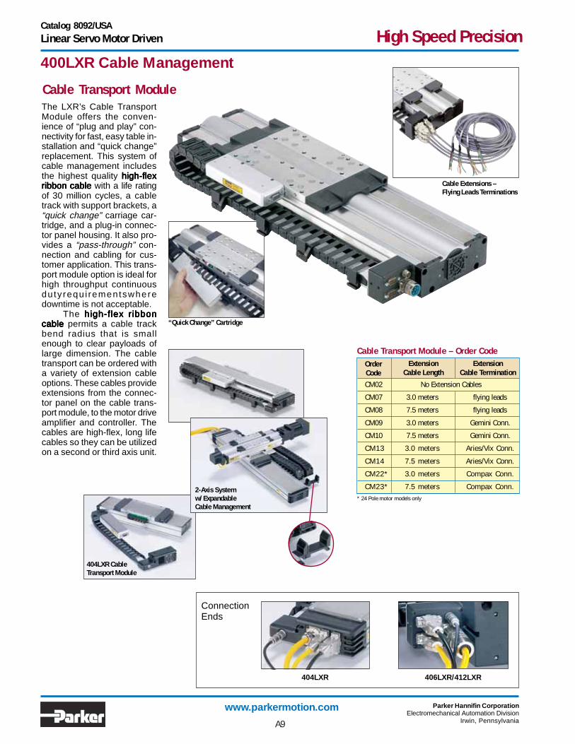
400LXR Cable Management
The LXR’s Cable TransportModule offers the conven-ience of “plug and play” con-nectivity for fast, easy table in-stallation and “quick change”replacement. This system ofcable management includesthe highest quality high-flexhigh-flexhigh-flexhigh-flexhigh-flexribbon cableribbon cableribbon cableribbon cableribbon cable with a life ratingof 30 million cycles, a cabletrack with support brackets, a“quick change” carriage car-tridge, and a plug-in connec-tor panel housing. It also pro-vides a “pass-through” con-nection and cabling for cus-tomer application. This trans-port module option is ideal forhigh throughput continuousduty requ i rementswheredowntime is not acceptable. The high-flex ribbonhigh-flex ribbonhigh-flex ribbonhigh-flex ribbonhigh-flex ribboncable cable cable cable cable permits a cable trackbend radius that is smallenough to clear payloads oflarge dimension. The cabletransport can be ordered witha variety of extension cableoptions. These cables provideextensions from the connec-tor panel on the cable trans-port module, to the motor driveamplifier and controller. Thecables are high-flex, long lifecables so they can be utilizedon a second or third axis unit.
“Quick Change” Cartridge
Cable Extensions –Flying Leads Terminations
ConnectionEnds
404LXR 406LXR/412LXR
404LXR Cleanroom Version
404LXR CableTransport Module
Cable Transport Module – Order CodeOrderCode
ExtensionCable Length
ExtensionCable Termination
* 24 Pole motor models only
CM02 No Extension Cables
CM07 3.0 meters flying leads
CM08 7.5 meters flying leads
CM09 3.0 meters Gemini Conn.
CM10 7.5 meters Gemini Conn.
CM13 3.0 meters Aries/Vix Conn.
CM14 7.5 meters Aries/Vix Conn.
CM22* 3.0 meters Compax Conn.
CM23* 7.5 meters Compax Conn.
A9
Cable Transport Module
2-Axis Systemw/ ExpandableCable Management
Catalog 8092/USALinear Servo Motor Driven High Speed Precision
www.parkermotion.com Parker Hannifin CorporationElectromechanical Automation Division
Irwin, Pennsylvania
CM03 3.0 meters flying leads
CM04 7.5 meters flying leads
CM05 3.0 meters Gemini Conn.
CM06 7.5 meters Gemini Conn.
CM11 3.0 meters Aries/Vix Conn.
CM12 7.5 meters Aries/Vix Conn.
CM20* 3.0 meters Compax Conn.
CM21* 7.5 meters Compax Conn.
400LXR Cable Management
OEM Cable SystemThe LXR’s unharnessedcable system is offered forOEMs and others who haveindependent methods ofrouting and managingcables. These systems offerthe “quick change” cartridge,“pass-through” connectionand round high-flex cables inlengths of 3.0 or 7.5 meters.They are available with fly-ing lead end terminations,Gemini, Aries, or Compax3Connectors.
User “Pass-Through” Cabling Feature• Pre-wired plug-in connection to the moving payload
• Nine user conductors for end-effectors or instruments
• High-Flex long life cables:Ribbon Cable – Transport Module SystemRound Cable – OEM System
Cable concerns regardingrouting and durability for pay-load or instrument signalsare addressed by the pass-through connectivity featureincluded with both of the LXRcable management systems.Nine pin D-connectors pro-
vided on the carriage (with thetransport module units) andthe cable connecting blockcombine with high-flex, longlife cables for easy setup anddependable performance.
406LXR with OEMcables and flying leads
Note: Extension Cables are available and can be ordered seperately:006-1743-01 (3 meters); 006-1743-02 (7.5 meters).
OEM Cable System – Order CodeOrderCode
ExtensionCable Length
ExtensionCable Termination
* 24 Pole motor models only
A10

Catalog 8092/USALinear Servo Motor Driven High Speed Precision
www.parkermotion.com Parker Hannifin CorporationElectromechanical Automation Division
Irwin, Pennsylvania
Digital Drive Options
Pre-configured for the LXR
Optimized for linear servo motors
Convenient connectorized cabling
Stable power-up operation
Input power: 95–480 VAC
Gemini Series
Simple Configuration:All digital drives shipped with the LXR product family come preconfigured with a motor file which includes electricalparameters to set continuous and peak currents, current loop compensation values, and default gain settings.Users will have the ability to override these parameters for special application requirements. Tuning is easy to useand intuitive for users and is available via a variety of methods. The motor and loading information must be knownby the drive to determine the baseline tuning gains. These are simple parameter entries the user can complete withthe help of standard Parker supplied front-end software tools.
The Gemini family offers a drive solution forevery LXR, from the 404LXR to the 412LXRwith iron core motor. Drives are offered sothat power levels are available to match thecontinuous and peak current requirementsof each LXR. The drive is easily configuredusing RS232/485 with a PC.
GV Digital Servo Drive:
• Sinusoidal commutation with hallsensors ensure proper phaseshifting
• Integrated encoder feedbackensures precise positioning
• Approvals: UL Recognition, cUL,CE for LVD, CE for EMC
• Torque, velocity, step & direction,and encoder tracking modesavailable
• 120/240VAC input
• Digital notch filters provide thetools to eliminate mechanicalresonance
• Simplified tuning and configuration
• Variable resolution for the encoderout as well as the command input
• PWM frequencies optimized forlinear motor support
• Stand-alone servo controller and drivein one small package
• Control features such as registration,motion profiles, S-curve velocityprofiling, electronic gearing, andconditional statements
• Program storage: Up to 32 programsor 190 lines of program code,expanded to 300KB for the GV6K
• Daisy chain up to 99 units
• Simplified configuration and tuning
• 8 programmable inputs and 6programmable outputs
• Compatibility with RS 232 /485
• Ethernet available as an option
GV Digital Controller/Servo Drive:A6A5A40A7A4 A42A41A9A8
A11

Catalog 8092/USALinear Servo Motor Driven High Speed Precision
www.parkermotion.com Parker Hannifin CorporationElectromechanical Automation Division
Irwin, Pennsylvania
Compax3 Series
The Aries family offers a robust and cost-effec-tive servo drive by power matching the drivewith the application requirements. Unlike thecompetition, the Aries family is designed with anopen architecture in mind, so it can also beconfigured for use with any manufacturer’smotion controller. Offered solely in a drive onlyconfiguration, the Aries provides a great value.
Aries Series
• 4 power levels available, matchedfor 404LXR, 406LXR, and 412LXRrequirements
• 120/240VAC input
• 20 MHz (post-quadrature) encoderinput
• Sinusoidal commutation with hallsensors ensure proper phase shifting
• Integrated encoder feedbackensures precise positioning
• Approvals: UL compliant, CE forLVD, CE for EMC
• +/-10 V torque control for use withany controller with a standard analogcommand output. Step and directioninput available as an option.
• Standard high-density D-subconnectors for easy connectivity inany system
• Simplified tuning and configurationwith easy to use front-end software
• Compact Design
• Status/fault LED indicators to confirmproper operation
Aries Digital Drive: A63A62
With its high-performance and modular design,the Compax3 family of industrial servo drivesand drive/controllers offers a new level of servoperformance and flexibility. The modular ca-pacity of the Compax3 family allows optionssuch as intelligent motion controllers, fieldbusinterfaces and industry standard motor feed-back. In addition, numerous expansion optionscan be added to the standard product in order tooptimize the capabilities required for today’sdemanding servo applications.
• 480VAC optimized for the 412LXRiron core design
• Available in 120/240VAC forslotless LXR designs
• Family of drives is power matchedto offer a solution for every400LXR table
• Easy-to-use wizards-basedconfiguration and programmingvia C3 ServoManager softwarepackage
• Full diagnostic, tuning, and 4-channel oscilloscope toolsprovided in the standard C3ServoManager softare
• Approvals: UL, cUL, CE for LVD,CE for EMC approval
• Configurable via RS232/485
• Status/fault LED indicators toconfirmproper operation
• Base servo drive
• +/- 10 V analog
• Step and direction
• Torque/velocity control
• Position control
• Encoder tracking
Drive Features: A50
• Full-featured programmable drive/controller
• IEC61131-3 programming flexibility
• PLCopen, Parker motion functionblocks
• Complex motion
• Profibus or CANopen optionsavailable
Indexer Features: A51
• Base indexer drive
• Up to 31 stored profiles
• Profile selected via digital inputs
• Multi-profile sequences
• Profibus or CANopen optionsavailable
Controller/Drive Features: A52
A12

Catalog 8092/USALinear Servo Motor Driven High Speed Precision
www.parkermotion.com Parker Hannifin CorporationElectromechanical Automation Division
Irwin, Pennsylvania
412LXR models with 24 pole iron core motors are offeredwith forced air or water cooling options to provide highercontinuous force values than standard convection cool-ing. Maximum continuous force is increased from 750Nto 970N with the forced air option and to 1720N with thewatercooled option.The CL1 convection cooling option utilizes conductionand convection to remove heat from the system. TheCL2 forced air cooling option forces air movement insidethe table body which enhances heat removal from themotor and critical electronic components. The CL3 andCL4 water cooling options circulate chilled water insidethe motor to rapidly and efficiently remove heat. The CL3option includes a motor prepared for water cooling with
412LXR Cooling Options
675 VDC Speed/Force Chart*
CL4 water cooled option showingwater line management
0.375" water line quick disconnect termination points onthe carriage. The CL4 option includes a motor prepared forwater cooling with 0.375" water lines routed through acarrier system from the moving carriage to a fixedconnection point on the base. This water coolingmanagement system is a pre-engineered solution thateliminates the headaches associated with designing,procuring and installing water line management. Bothwater cooling options utilize Parker 0.375" tubing quickdisconnects for easy connection. The minimum flowrecommendation is 1.0 GPM with a water pressure not toexceed 50 psi. For closed loop cooling systems, a 2000watt “chiller” is recommended.
CL2 forced air option
CL2CL1
CL3 option - water coolingcarriage connections
A13
340VDC
Peak force - all cooling methods
Continuous force - water cooled
Continuous force - forced air cooled
Continuous force - convection cooled
0 0.5 1.0 1.5 2.0 2.5 3.0 3.5 4.0 4.5 5.0
500
1000
1500
2000
2500
3000
Speed (m/sec)
For
ce (N
)
0
* Note: dashed lines indicate the maximum values when using a 340 VDC input to the motor.
CL3 CL4
CL3 CL4
CL2
CL1

Catalog 8092/USALinear Servo Motor Driven High Speed Precision
www.parkermotion.com Parker Hannifin CorporationElectromechanical Automation Division
Irwin, Pennsylvania
Two locating dowelholes ( P1 option)shown in 404LXRcarriage
Cleanroom compatible linear tables are often required forlaboratory and production applications in industries suchas semiconductor, life science, electronics, and pharma-ceuticals. 400LXR tables with cleanroom preparation, were tested inParker’s vertical laminar flow work station, which utilizesULPA filters to produce an environment having a cleanli-ness of class 1 prior to testing. Tables were tested in avariety of orientations with sampling both below the tableand at the carriage mounting surface. Laminar flow rate is0.65 inches W.C.Special cleanroom testing can be provided upon request.For more information on cleanroom testing, contact aParker Applications Engineer at 800-245-6903.
400LXR Cleanroom Preparation
Standard Cleanroom Preparation
400LXR Cleanroom Compatibility
250 mm/sec 10 1
500 mm/sec 25 1
1000 mm/sec 50 5
2000 mm/sec 250 25
3000 mm/sec 500 100
ClassTableVelocity 4.5” below table At carriage surface
A room in which the concentration of airborne particlesis controlled within defined limits. Federal Standard209E statistically defines the allowable number of parti-cles per cubic foot of air. The chart (right) describes the conditions that must bemaintained for the cleanroom to have a specific “class”rating.
About Cleanrooms
404LXR with cleanroomclass 10 modification
Testing at 4.5 inches below table
Testing at carriage mounting surface
1 3 5 7.5 3 1 0
1 0 350 7 5 3 0 1 0 0
100 n/a 750 300 100 0
1000 n/a n/a n/a 1000 7
10000 n/a n/a n/a 10000 7 0
100000 n/a n/a n/a 100000 700
Number of Allowable ParticlesClass 0.1 0.2 0.3 0.5 5
(Measured particle size in microns [µm])
R2
P_Dowel Pinning
• Stringent cleaning and handling measures• Cleanroom rated lubrication• Strip seal replaced with hard shell cover
A14
Standard dowel pin locating holes P1 are offered onall 400LXR units to facilitate repeatable mounting oftooling or payload. In addition, pinning options P2 & P3 are offeredfor precise orthogonal mounting of the second axis in amulti-axis system. In this case, the bottom side of thetable base is match drilled and reamed to the first axisto provide exact orthogonal location. This convenientoption eliminates concerns regarding contamination ordamage often associated with machining for locatingpins in an assembled unit.

Catalog 8092/USALinear Servo Motor Driven High Speed Precision
www.parkermotion.com Parker Hannifin CorporationElectromechanical Automation Division
Irwin, Pennsylvania
18.0
110.0M6
C'boreCentersof ToeClamps
"E"�18.0
110.0
Qty (2) 4.0 Dia.Pin Holes
Qty (4) Mounting Holes (top)M6 x 1.0 Thd.
50.0
18.0 40.0
70.0
60.0 70.0
152.0
60.0
P/N 003-3123-01 AUXILLARYP/N 003-2969-01 ENCODER-HALLS
P/N 003-3122-01 LIMIT-HOMEP/N 006-1720-01 MOTOR CABLE
LIM
ITS
MO
TOR
AUX.
ENC.
/HAL
L
88.0(Mounting Holes)
85.0(Pin Holes)
0.020
+ 0.012- 0.000
150.0
220.0
Z4-Negative Z3-Center Z2-Positive
A
A
72.5
98.050.0
15.085.0
100.015.0
75.0
M5 x 0.8 TappedHoles Qty "D" Holes
"B" Spaces @ 100.0 mm = "C" "B" Spaces @ 100.0 mm = "C"
18.0
"A"
40.0
Recommended Clearancefor Cable Carrier
Minimum Clearance Required for Extension Cable Connector Clearance
40.0
1/2 Travel - 10.0 mm 1/2 Travel - 10.0 mm
LIM
ITS
MO
TOR
AUX.
ENC.
/HAL
L
OEM Cables (Strip Seal/Hardcover)
Cable Module (Strip Seal/Hardcover)
Cable Module/Strip Seal Cable Module/Hardcover
OEM Cables/Strip Seal OEM Cables/Hardcover
"A"
Top View(With Cable Transport Module)
Front ViewZ-Channel Location
Bottom View
152.0
148.0 148.0
Qty (2) 4.0 Dia. Pin Holes0.020
+ 0.012- 0.000
End Views A-A
2D & 3DCADfiles parkermotion.com
Download from
404LXR Series Dimensions (mm)
B C D ETravel (mm)Model
404T00LXR 50 368.0 1 100.0 12 346.0
404T01LXR 100 418.0 1 100.0 12 396.0
404T02LXR 150 468.0 1 100.0 12 446.0
404T03LXR 200 518.0 1 100.0 12 496.0
404T04LXR 250 568.0 1 100.0 12 546.0
404T05LXR 300 618.0 2 200.0 16 596.0
404T06LXR 350 668.0 2 200.0 16 646.0
404T07LXR 400 718.0 2 200.0 16 696.0
404T09LXR 500 818.0 3 300.0 20 796.0
404T11LXR 600 918.0 3 300.0 20 896.0
404T13LXR 700 1018.0 4 400.0 24 996.0
404T15LXR 800 1118.0 4 400.0 24 1096.0
404T17LXR 900 1218.0 5 500.0 28 1196.0
404T19LXR 1000 1318.0 5 500.0 28 1296.0
Dim A
A15

Catalog 8092/USALinear Servo Motor Driven High Speed Precision
www.parkermotion.com Parker Hannifin CorporationElectromechanical Automation Division
Irwin, Pennsylvania
Pinning Option
No multi-axis pinning
X axis transfer pinning toY or Z axis - 30 arc secondsY axis transfer pinning toX axis - 30 arc seconds
Digital Drive
No Drive
Gemini Drive GV-U6E
Gemini Controller/Drive GV6-U6E
Gemini Controller/Drive GV6K-U6E
Aries Drive AR-04AE
Environmental
Strip Seal
Hard Cover w/ Class 10 Cleanroom Prep
Hard Cover without Cleanroom Prep
Encoder Option
None .......
1.0 µm Resolution
0.5 µm Resolution
0.1 µm Resolution
5.0 µm Resolution
Sine Output Encoder
Z Channel Location*
None .......
Positive End Position
Center Position
Negative End Position
P1
P2
*Refer to dimension drawing on page A15.
E1
E5
Z1
Z2
Z3
Z4
E2
E3
E4
E7
Cable Trans Mod. w/3.0 m-Gemini*
Cable Trans Mod. w/7.5 m-Gemini*
3.0 m OEM Cable Set-Aries/Vix
7.5 m OEM Cable Set-Aries/Vix
Cable Trans Mod. w/3.0 m-Aries/Vix*
Cable Trans Mod. w/7.5 m-Aries/Vix*
Cable Management
No Cables - Free Travel
Cable Transport Module (only)
3.0 m OEM Cable Set-FL
7.5 m OEM Cable Set-FL
3.0 m OEM Cable Set-Gemini
7.5 m OEM Cable Set-Gemini
Cable Trans Mod. w/3.0 m-FL*
Cable Trans Mod. w/7.5 m-FL*
Series ...........
Travel (mm) 8 PoleMotor
50 ........................
100........................
150........................
200........................
250........................
300........................
350........................
400........................
500........................
600........................
700........................
800........................
900........................
1000........................
Model ..............................
Mounting (metric)..........
Grade
Precision ............................
Drive TypeFree Travel (No Motor) .......
8 Pole Motor ......................
Home SensorNone-Free Travel (only) .....
N.C. Current Sinking .........
N.O. Current Sinking .........
N.C. Current Sourcing .......
N.O. Current Sourcing .......
Limit Sensor
None-Free Travel (only) .....
N.C. Current Sinking .........
N.O. Current Sinking .........
N.C. Current Sourcing .......
N.O. Current Sourcing .......
T04 LXR M P H3D13404
LXR
M
P
D3
D13
H2
H3
H4
H5
L1
L4
L5
E2 R1Z2 A4 P1L2
H1
L3
L2
Order Example
404LXR - How to Order
404
T00
T01
T02
T03
T04
T05
T06
T07
T09
T11
T13
T15
T17
T19
* Extension Cable for pass throughconnection is available and can beordered seperately:006-1743-01 (3 meters)006-1743-02 (7.5 meters)
CM09
CM01
CM03
CM04
CM05
CM06
CM07
CM02
CM08
CM10
CM11
CM12
CM13
CM14
CM09-
P3
A16
A1
A4
A5
A6
A62
R1
R2
R3

Catalog 8092/USALinear Servo Motor Driven High Speed Precision
www.parkermotion.com Parker Hannifin CorporationElectromechanical Automation Division
Irwin, Pennsylvania
168.0 Ctr'd
M6 x 1.0 Thd.Carriage Mtg. Holes Qty 20
Top View(with Cable Transport Module)
Front View(Z-Channel Location)
110.0 Ctr'd80.0 Ctr'd
Z4*Negative
1/2 "A"
50.0Ctr'd
Bottom View
100.0Ctr'd136.0Ctr'd
6.5
"C" Spaces @ 100.0 = "D" "C" Spaces @ 100.0 = "D"
"F" Spaces @ 100.0 = "G"
15.0
65.0 150.0215.0
232.5
150.0
55.0
200.0
69.9
84.0 Toe Clamp MountingOptional
75.0
6.5
50.0Ctr'd
80.0Ctr'd
116.0�Ctr'd
"B" Mtg. HolesM6 x 1.0 Th'd
"E" C'bored Mtg.Holes - (Farside)for M6 Cap Screws
"A"
Z2*Positive
Z3*Center
1/2 Travel - 10 mm
*Z2, Z3, Z4 shows Carriage Center-line Location for Selected Z-Channel Position
End View(with OEM Cable System)
Top View(with OEM Cable System)
1/2 Travel - 10 mm
8 Pole Carriage = 288 mm12 Pole Carriage = 373 mm
46.0Ctr'd
50.0Ctr'd
130.0Ctr'd
136.0Ctr'd
25.0
"F" Spaces @ 100.0 = "G"
Qty (2) 5.0 Dia.Pin Holes+ 0.012- 0.000
Qty (2) 5.0 �Dia.Pin Holes
+ 0.012- 0.000
A B C D E F GTravel (mm)
8 PoleModel
406T01LXR406T01LXR406T01LXR406T01LXR406T01LXR 50 408 8 1 100.0 12 1 100.0406T02LXR406T02LXR406T02LXR406T02LXR406T02LXR 150 508 8 1 100.0 12 1 100.0406T03LXR406T03LXR406T03LXR406T03LXR406T03LXR 250 608 12 2 200.0 16 2 200.0406T04LXR406T04LXR406T04LXR406T04LXR406T04LXR 350 708 12 2 200.0 16 2 200.0
406T05LXR406T05LXR406T05LXR406T05LXR406T05LXR 450 808 16 3 300.0 20 3 300.0
406T06LXR406T06LXR406T06LXR406T06LXR406T06LXR 550 908 16 3 300.0 20 3 300.0
406T07LXR406T07LXR406T07LXR406T07LXR406T07LXR 650 1008 20 4 400.0 24 4 400.0
406T08LXR406T08LXR406T08LXR406T08LXR406T08LXR 750 1108 20 4 400.0 24 4 400.0
406T09LXR406T09LXR406T09LXR406T09LXR406T09LXR 850 1208 24 5 500.0 28 5 500.0
406T10LXR406T10LXR406T10LXR406T10LXR406T10LXR 950 1308 24 5 500.0 28 5 500.0
406T11LXR406T11LXR406T11LXR406T11LXR406T11LXR 1200 1558 32 7 700.0 32 6 600.0
406T12LXR406T12LXR406T12LXR406T12LXR406T12LXR 1450 1808 36 8 800.0 40 8 800.0406T13LXR406T13LXR406T13LXR406T13LXR406T13LXR 1700 2058 40 9 900.0 44 9 900.0
406T14LXR406T14LXR406T14LXR406T14LXR406T14LXR 1950 2308 44 10 1000.0 48 10 1000.0
Travel (mm)12 Pole
N/A50
150250350
450
550
650
750
850
1100
13501600
1850
406LXR Series Dimensions (mm)12 Pole Slotless Motor
A17
2D & 3DCADfiles parkermotion.com
Download from

Catalog 8092/USALinear Servo Motor Driven High Speed Precision
www.parkermotion.com Parker Hannifin CorporationElectromechanical Automation Division
Irwin, Pennsylvania
Pinning Option
No multi-axis pinning
X axis transfer pinning toY or Z axis - 30 arc secondsY axis transfer pinning toX axis - 30 arc seconds
Digital Drive
No Drive
Gemini Drive GV-U6E
Gemini Controller/Drive GV6-U6E
Gemini Controller/Drive GV6K-U6E
Aries Drive AR-04AE
Environmental
Strip Seal
Hard Cover w/ Class 10 Cleanroom Prep
Encoder Option
None .......
1.0 µm Resolution
0.5 µm Resolution
0.1 µm Resolution
5.0 µm Resolution
Sine Output Encoder
Z Channel Location*
None .......
Positive End Position
Center Position
Negative End Position
Series ...........
Travel (mm)8 Pole 12 PoleMotor Motor
50 .......... n/a ........
150 ........... 50 ........
250 ......... 150 ........
350 ......... 250 ........
450 ......... 350 ........
550 ......... 450 ........
650 ......... 550 ........
750 ......... 650 ........
850 ......... 750 ........
950 ......... 850 ........
1200 ....... 1100 ........
1450 ....... 1350 ........
1700 ....... 1600 ........
1950 ....... 1850 ........
Model ..............................
Mounting (metric)..........
GradePrecision ............................
Drive TypeFree Travel (No Motor)
8 Pole Carriage (no mtr.) ...
12 Pole Carriage (no mtr.) ...
Linear Motor
8 Pole Motor Carriage .....
12 Pole Motor Carriage .....
Home SensorNone - Free Travel (only) ...
N.C. Current Sinking .........
N.O. Current Sinking .........
N.C. Current Sourcing .......
N.O. Current Sourcing .......
Limit SensorNone - Free Travel (only) ...
N.C. Current Sinking .........
N.O. Current Sinking .........
N.C. Current Sourcing .......
N.O. Current Sourcing .......
T09 LXR H2406
LXR
M
P
D3
D5
H2
H3
H4
H5
L1
L4
L5
E2 R1Z2 A4 P1
H1
L3
D13
D15
L2
Order Example
406LXR - How to Order
406
T01
T02
T03
T04
T05
T06
T07
T08
T09
T10
T11
T12
T13
T14
* Extension Cable for pass through connection isavailable and can be ordered seperately:#006-1743-01 (3 meters); #006-1743-02 (7.5 meters).
Cable Trans Mod. w/ 3.0 m-Gemini*
Cable Trans Mod. w/ 7.5 m-Gemini*
3.0 m OEM Cable Set-Aries
7.5 m OEM Cable Set-Aries
Cable Trans Mod. w/ 3.0 m-Aries*
Cable Trans Mod. w/ 7.5 m-Aries*
CM01
CM03
CM04
CM05
CM06
CM07
CM02
CM08
CM10
CM11
CM12
CM13
CM14
CM09
Cable Management
No Cables - Free Travel
Cable Transport Module (only)
3.0 m OEM Cable Set-FL
7.5 m OEM Cable Set-FL
3.0 m OEM Cable Set-Gemini
7.5 m OEM Cable Set-Gemini
Cable Trans Mod. w/ 3.0 m-FL*
Cable Trans Mod. w/ 7.5 m-FL*
M P D13 CM09
P1
P2
*Refer to dimension drawing on page A17
P3
A18
A1
A4
A5
R1
R2
A6
A62
E1
E5
Z1
Z2
Z3
Z4
E2
E3
E4
E7
L2

Catalog 8092/USALinear Servo Motor Driven High Speed Precision
www.parkermotion.com Parker Hannifin CorporationElectromechanical Automation Division
Irwin, Pennsylvania
300.0
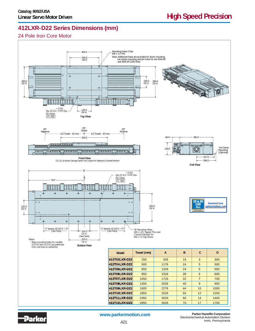
Note: Additional holes are provided for direct mounting, toe clamp mounting and pin holes for the 404LXR and 406LXR (CAD files)
250.0Ctr'd
Qty 8 Mounting Holes (Top)M6 x 1.0 Thd.
100.0Ctr'd.
266.0Ctr'd.
64.8 285.0
157.0
Toe ClampMounting (Optional)
105.0
404.0
120.0Ctr'd
"A"
"A/2"C
L
CL
240.0Ctr'd
"B" Mounting HolesM8 x 1.25 Tapped Thru and C'bored (farside) for �M6 x 1.0 Cap Screw
"C" Spaces @ 100.0 = "D"(See Notes)
"C" Spaces @ 100.0 = "D"(See Notes) 100.0
Ctr'd(See Note)
260.0Ctr'd
Top View
Front View
End View
Bottom View
Notes:Base mounting holes for models412T10 and 412T12 are patternedfrom one hole on centerline
168.0
260.0�Ctr'd
120.0�Ctr'd
Z4*Negative
Z2*Positive
Z3*Center
1/2 Travel - 10 mm 1/2 Travel - 10 mm
*Z2, Z3, Z4 shows Carriage Center-line Location for Selected Z-Channel Position
.022
Qty (2) 8.0 Dia.Pin Holes
+ 0.016- 0.000
.022
Qty (2) 8.0 Dia.Pin Holes
+ 0.016- 0.000
B C DTravel (mm)Model
412T01LXRD-15 412T01LXRD-15 412T01LXRD-15 412T01LXRD-15 412T01LXRD-15 150 764 12 2 200
412T02LXRD-15 412T02LXRD-15 412T02LXRD-15 412T02LXRD-15 412T02LXRD-15 250 864 16 3 300
412T03LXRD-15 412T03LXRD-15 412T03LXRD-15 412T03LXRD-15 412T03LXRD-15 350 964 16 3 300
412T04LXRD-15 412T04LXRD-15 412T04LXRD-15 412T04LXRD-15 412T04LXRD-15 650 1264 24 5 500
412T05LXRD-15 412T05LXRD-15 412T05LXRD-15 412T05LXRD-15 412T05LXRD-15 800 1414 24 5 500
412T06LXRD-15412T06LXRD-15412T06LXRD-15412T06LXRD-15412T06LXRD-15 1000 1614 28 6 600
412T07LXRD-15 412T07LXRD-15 412T07LXRD-15 412T07LXRD-15 412T07LXRD-15 1200 1814 32 7 700
412T08LXRD-15 412T08LXRD-15 412T08LXRD-15 412T08LXRD-15 412T08LXRD-15 1500 2114 40 9 900
412T09LXRD-15 412T09LXRD-15 412T09LXRD-15 412T09LXRD-15 412T09LXRD-15 1750 2364 44 10 1000
412T10LXRD-15412T10LXRD-15412T10LXRD-15412T10LXRD-15412T10LXRD-15 2000 2614 50 12 1200
412T11LXRD-15 412T11LXRD-15 412T11LXRD-15 412T11LXRD-15 412T11LXRD-15 2500 3114 60 14 1400
412T12LXRD-15 412T12LXRD-15 412T12LXRD-15 412T12LXRD-15 412T12LXRD-15 3000 3614 70 17 1700
A
412LXR-D15 Series Dimensions (mm)12 Pole Slotless Motor
A19
2D & 3DCADfiles parkermotion.com
Download from

Catalog 8092/USALinear Servo Motor Driven High Speed Precision
www.parkermotion.com Parker Hannifin CorporationElectromechanical Automation Division
Irwin, Pennsylvania
Pinning Option
No multi-axis pinningX axis transfer pinning toY or Z axis - 30 arc secondsY axis transfer pinning toX axis - 30 arc seconds*
Digital Drive
No Drive
Gemini Drive GV-U12E
Gemini Controller/Drive GV6-U12E
Gemini Controller/Drive GV6K-U12E
Aries Drive AR-08AE
Environmental
Class 1000, Strip Seals
Class 10 Cleanroom Prep
EncoderNone
1.0 µm Resolution Linear
0.5 µm Resolution Linear
0.1 µm Resolution Linear
5.0 µm Resolution Linear
Sine Output Encoder
Z Channel Location*
None
Positive End Position
Center Position
Negative End Position
412LXR - How to Order12 Pole Slotless Linear Motor
Series ...........
Travel (mm) 12 Pole Motor
1200 ...
1500 ...
1750 ...
2000 ...
2500 ...
3000 ...
Model ...............................
Mounting (metric) ...........
GradePrecision ............................
Drive TypeFree Travel (No Motor) .......
12 Pole Motor ....................
Home SensorNone-Free Travel (only) .....
N.C. Current Sinking .........
N.O. Current Sinking .........
N.C. Current Sourcing .......
N.O. Current Sourcing .......
Limit SensorNone-Free Travel (only) .....
N.C. Current Sinking .........
N.O. Current Sinking .........
N.C. Current Sourcing .......
N.O. Current Sourcing .......
LXR
M
D5
H1
H4
H5
P1
P2
A1
D15
H3
H2
Order Example
A7
A8
T07
T08
T09
T10
T11
T12
P
L1
L4
L5
L3
L2
P3
*Refer to dimension drawing on page A19.
412
T01
T02
T03
T04
T05
T06
150 ...
250 ...
350 ...
650 ...
800 ...
1000 ...
412
Refer to page A22 for 24 pole iron coremotor drive.
T09 LXR P D15 H3M L3 CM09 Z2 E2 R1 A7 P1
A9
A63
R1
R2
CM01
CM03
CM04
CM02
Cable ManagementNo Cables - Free Travel
Cable Transport Module (only)
3.0 m OEM Cable Set-FL
7.5 m OEM Cable Set-FL
3.0 m OEM Cable Set-Gemini
7.5 m OEM Cable Set-Gemini
Cable Trans Mod. w/ 3.0 m-FL*
Cable Trans Mod. w/ 7.5 m-FL*
Cable Trans Mod. w/ 3.0 m-Gemini*
Cable Trans Mod. w/ 7.5 m-Gemini*
3.0 m OEM Cable Set-Aries
7.5 m OEM Cable Set-Aries
Cable Trans Mod. w/ 3.0 m-Aries*
Cable Trans Mod. w/ 7.5 m-Aries*
CM05
CM06
CM07
CM08
CM09
CM10
CM11
CM12
CM13
CM14
A20
* Extension Cable for pass through connection isavailable and can be ordered seperately:#006-1743-01 (3 meters); #006-1743-02 (7.5 meters).
E1
E5
Z1
Z2
Z3
Z4
E2
E3
E4
E7
*P3 Option includes a required15 mm thick adapter.
Catalog 8092/USALinear Servo Motor Driven High Speed Precision
www.parkermotion.com Parker Hannifin CorporationElectromechanical Automation Division
Irwin, Pennsylvania
400.0
Note: Additional holes are provided for direct mounting, toe clamp mounting and pin holes for the 404LXR and 406LXR (CAD files)
250.0Ctr'd
Mounting Holes (Top)M6 x 1.0 Thd.
100.0Ctr'd.
266.0Ctr'd.
66.5 285.0
157.0
Toe ClampMounting (Optional)
130.0
504.0
120.0Ctr'd.
"A"
"A/2"C
240.0Ctr'd.
"C" Spaces @ 100.0 = "D"(See Note)
"C" Spaces @ 100.0 = "D"(See Note) 100.0
Ctr'd.(See Note)
260.0Ctr'd.
Top View
Front View
End View
Bottom View
Notes:Base mounting holes for models412T10 and 412T12 are patternedfrom one hole on centerline
168.0
260.0Ctr'd.
120.0Ctr'd.
Z4*Negative
Z2*Positive
Z3*Center
1/2 Travel - 10 mm 1/2 Travel - 10 mm
*Z2, Z3, Z4 shows Carriage Center-line Location for Selected Z-Channel Position
.022
Qty (2) 8.0 Dia.Pin Holes
+ 0.016- 0.000
.022
Qty (2) 8.0 Dia.Pin Holes
+ 0.016- 0.000
L
"B" Mounting HolesM8 x 1.25 Tapped Thru and C'bored (farside) for �M6 x 1.0 Cap Screw
412LXR-D22 Series Dimensions (mm)24 Pole Iron Core Motor
B C DTravel (mm)Model
412T03LXR-D22412T03LXR-D22412T03LXR-D22412T03LXR-D22412T03LXR-D22 200 926 16 3 300
412T04LXR-D22412T04LXR-D22412T04LXR-D22412T04LXR-D22412T04LXR-D22 500 1176 24 5 500
412T05LXR-D22412T05LXR-D22412T05LXR-D22412T05LXR-D22412T05LXR-D22 650 1326 24 5 500
412T06LXR-D22412T06LXR-D22412T06LXR-D22412T06LXR-D22412T06LXR-D22 850 1526 28 6 600
412T07LXR-D22412T07LXR-D22412T07LXR-D22412T07LXR-D22412T07LXR-D22 1050 1726 32 7 700
412T08LXR-D22412T08LXR-D22412T08LXR-D22412T08LXR-D22412T08LXR-D22 1350 2026 40 9 900
412T09LXR-D22412T09LXR-D22412T09LXR-D22412T09LXR-D22412T09LXR-D22 1600 2276 44 10 1000
412T10LXR-D22412T10LXR-D22412T10LXR-D22412T10LXR-D22412T10LXR-D22 1850 2526 50 12 1200
412T11LXR-D22412T11LXR-D22412T11LXR-D22412T11LXR-D22412T11LXR-D22 2350 3026 60 14 1400
412T12LXR-D22412T12LXR-D22412T12LXR-D22412T12LXR-D22412T12LXR-D22 2850 3526 70 17 1700
A
A21
2D & 3DCADfiles parkermotion.com
Download from

Catalog 8092/USALinear Servo Motor Driven High Speed Precision
www.parkermotion.com Parker Hannifin CorporationElectromechanical Automation Division
Irwin, Pennsylvania
CoolingConvection cooling
Forced air cooling
Water cooling
Water cooling with external ass’y.
Environmental
Class 1000, Strip Seals
Class 10 Cleanroom Prep
CM01
CM05
CM06
412LXR - How to Order - 24 Pole Iron Core Motor
Series ...........
Travel (mm) 24 Pole Motor
1600 ...
1850 ...
2350 ...
2850 ...
...
Model ...............................
Mounting (metric) ...........
GradePrecision ............................
Drive TypeFree Travel (No Motor)
24 Pole Motor ....................
Home SensorNone-Free Travel (only) .....
N.C. Current Sinking .........
N.O. Current Sinking .........
N.C. Current Sourcing .......
N.O. Current Sourcing .......
Limit SensorNone-Free Travel (only) .....
N.C. Current Sinking .........
N.O. Current Sinking .........
N.C. Current Sourcing .......
N.O. Current Sourcing .......
P1
P2
Order Example
200 ...
500 ...
650 ...
850 ...
1050 ...
1350 ...
P3
*Refer to dimension drawing on page A21.
P1 CL1T09 LXR M P D22 H3 L3 CM02 Z3 E2 R1 A40
A42
A50
412
T03
T04
T05
T06
T07
T08
T09
T10
T11
T12
Cable ManagementNo Cables - Free Travel .................
Cable Transport Module (only) ........
3.0 m OEM Cable Set-FL ................
7.5 m OEM Cable Set-FL ................
3.0 m OEM Cable Set-Gemini...........
7.5 m OEM Cable Set-Gemini..........
Cable Trans Mod. w/3.0 m-FL*.......
Cable Trans Mod. w/7.5 m-FL*.......
Cable Trans Mod. w/3.0 m-Gemini*...
Cable Trans Mod. w/7.5 m-Gemini*...
3.0 m OEM Cable Set-Compax .......
7.5 m OEM Cable Set-Compax .......
Cable Trans Mod. w/3.0 m-Compax*
Cable Trans Mod. w/7.5 m-Compax*
Refer to page A20 for 12 pole slotless motor drive.
412
CM07
CM04
CM03
CM02
CM08
CM09
CM10
CM20
CM21
CM22
CM23
LXR
M
P
D6
D22
H1
H4
H5
H3
H2
L1
L4
L5
L3
L2
R1
E4
R2
Z1
Z2
A41
A40
A1
Pinning OptionNo multi-axis pinning
X axis transfer pinning toY or Z axis - 30 arc seconds
Y axis transfer pinning toX axis - 30 arc seconds*
Digital Drive
No Drive
Gemini Drive GV-H20E
Gemini Controller/Drive GV6-H20E
Gemini Controller/Drive GV6K-H20E
Compax Drive S150-V4-F12-I10-T10
Compax Indexer S150-V4-F12-I11-T11
Compax Controller /Drive S150-V4-F12-I10-T30
A51
A52
Encoder Option
None
1.0 µm Resolution - Optical
0.5 µm Resolution - Optical
0.1 µm Resolution - Optical
5.0 µm Resolution - Optical
Sine Output - Optical
Z Channel Location*
None
Positive End Position
Center Position
Negative End Position
E1
E2
E3
E5
E7
Z3
Z4
CL1
CL4
CL2
CL3
A22
* Extension Cable for pass through connection isavailable and can be ordered seperately:#006-1743-01 (3 meters); #006-1743-02 (7.5 meters).
*P3 Option includes a required15 mm thick adapter.

Catalog 8092/USALinear Servo Motor Driven High Speed Precision
www.parkermotion.com Parker Hannifin CorporationElectromechanical Automation Division
Irwin, Pennsylvania
DXL Series Dual Carriage Linear Motor Table
FeaturesIndependently driven dual carriages
Outstanding carriage to carriageco-planar motion
Ultra precise velocity controland responsiveness
Selectable encoder resolutionsdown to 20 nanometers
Tooling reference surface anddowel holes on each carriage
The DXL dual carriage positioning table provides a pre-cision platform for controlled translation and positioningof two independent carriages on the same linear travelpath. The DXL ensures superior carriage to carriage flat-ness and coplanar motion by providing a common preci-sion ground base and bearing ways for both carriages.Each carriage is independently driven by a cogfree,ironless linear motor to minimize velocity ripple and opti-mize responsiveness to match a complex motion profile(refer to chart on page A25). Extremely high resolutionlinear encoders provide the critical position data that al-lows superior velocity control and responsiveness nec-essary to optimize the precision control of the movingcarriages. The twin carriages can be programmed to movein tandem, in opposing directions or independently withor without any ratio between the carriages. The DXL can be used in many precision motion ap-plications but is especially effective for fiber optic indus-try applications where smooth, highly controlled velocityand motion path is employed for fusing fibers. Other ap-plications include medical device manufacturing andimaging applications where focal distancemust be precisely controlled. Loaded with “ease of use” features, the DXL is de-signed to save time and effort. The DXL base includesa tooling edge parallel to the travel path.User tooling can be precisely located within 25 micronsof the actual travel path of the positioner using the tool-ing reference features. A unique cover design preventscontamination (such as small fiber strands) from enter-ing the positioner. The DXL is available with preconfigureddigital servo drives that are compatible with all industrystandard motion controllers. All DXL units ship completewith performance certification and laser interferometertest reports.
• Cogfree linear motors with no moving cables
• One base and bearing way sets - common to bothcarriages
• Extremely high resolution optical encoderswith digital output
• Hardshell cover protects internal components (IP30)
• Home sensor aligned to encoder referencemarker for precise homing
• Adjustable end of travel sensors
• Tooling reference surface is aligned within25 microns of the actual travel path
• Cleanroom compatible
Key Attributes
Hard Shell CoverHard Shell CoverHard Shell CoverHard Shell CoverHard Shell Cover
Dowel Pin HolesDowel Pin HolesDowel Pin HolesDowel Pin HolesDowel Pin Holes
Carriage ToolingCarriage ToolingCarriage ToolingCarriage ToolingCarriage ToolingRef. SurfacesRef. SurfacesRef. SurfacesRef. SurfacesRef. Surfaces
Base ToolingBase ToolingBase ToolingBase ToolingBase ToolingRef. SurfaceRef. SurfaceRef. SurfaceRef. SurfaceRef. Surface
Motor and HallMotor and HallMotor and HallMotor and HallMotor and Halleffect cable witheffect cable witheffect cable witheffect cable witheffect cable withflying leadsflying leadsflying leadsflying leadsflying leadsterminationterminationterminationterminationtermination
EncoderEncoderEncoderEncoderEncoderCableCableCableCableCable
Limit andLimit andLimit andLimit andLimit andHome CableHome CableHome CableHome CableHome Cable
A23
zt02

Catalog 8092/USALinear Servo Motor Driven High Speed Precision
www.parkermotion.com Parker Hannifin CorporationElectromechanical Automation Division
Irwin, Pennsylvania
Travel (Z-axis) 35 mm (per carriage – limit to limit)Rated Load Capacity 150 KgMaximum Acceleration 2 GsPeak Force 44 NContinuous Force 19 NResolution
E2 1.0 µm digital encoderE3 0.5 µm digital encoderE4 0.1 µm digital encoderE5 5.0 µm digital encoderE7 Sine Output encoderE8 0.02 µm digital encoder
Positional Accuracy(1,2,4) 3 µmPositional Repeatability(1,2)
1.0 µm digital encoder +/-2 µm0.5 µm digital encoder +/-1 µm0.1 µm digital encoder +/-0.5 µm5.0 µm digital encoder +/-10 µmSine Output encoder (interpolation dependent)0.02 µm digital encoder +/-0.3 µm
Maximum Velocity1.0 µm digital encoder 500 mm/sec(3)
0.5 µm digital encoder 500 mm/sec(3)
0.1 µm digital encoder 300 mm/sec5 µm digital encoder 500 mm/secSine Output encoder 500 mm/sec(3)
0.02 µm digital encoder 100 mm/secDuty Cycle 100%Linear Bearing – Coeff. of Friction 0.01Flatness +/-2 µmStraightness +/-2 µmUnit Weight 7.1 KgCarriage Weight 1.6 KgLimit/Home Sensors Refer to page B15
1 Measured at the carriage center, 35 mm off mounting surface.
2 With slope correction value provided.
3 Speed is limited due to acceleration limit (2g’s) and total travel of stage (35 mm).Higher speeds can be commanded but constant velocity will not be reached due to required acceleration distance.
4 Based on 0.1 micron or finer encoder resolution.
Table Life/Load ChartCompression (normal load)
The graphs provide a preliminary evaluationof the support bearing life/load characteristics.The curves show the life/load relationship whenthe applied load is centered on the carriage,normal (perpendicular) to the carriage mountingsurface. For final evaluation of life vs load,including off center, tension, and side loadsrefer to the charts and formulas found onpages B13 and B14.
Specifications
A24
Life vs Compression Load
1,0000 200 400 600 800 1000 1200 1400 1600 1800 2000
Load (N)
100,000
10,000Km

Catalog 8092/USALinear Servo Motor Driven High Speed Precision
www.parkermotion.com Parker Hannifin CorporationElectromechanical Automation Division
Irwin, Pennsylvania
-0.000+0.012
ENCODERENCODERMOTORMOTOR HALLSHALLS
LIMIT/HOMELIMIT/HOME
M6 x 1.0 x 8.0 DPQty (8) per Carriage
40.0
20.0
40.0
30.0
25.0 125.0
40.0(Pin Holes)
50.0(Pin Holes)
125.0150.0
450.0
Top View
Front View End View
50.0�Nominal
17.5 1/2 Travel17.5 1/2 Travel 17.5 1/2 Travel
55.5
All Cable Ends are Flying LeadsMotor, Hall, & Limit Home Cables 3 M Length
Encoder Cable 1 M Length
17.5 1/2 Travel
2.1
40.0 140.0 152.4
C'bores for M6180.0E" 4.00
Ref. H7 Tol.Pin Holes
Qty 4 per Carriage
10.0
M4 x 0.8 x 8.0 DPQty. (8) per Carriage
Overall length increases by 30 mm for minimum cable clearance
DXL Series Dimensions (mm)
Time/Distance ChartDistance against time (linear)
The linearity of this plot illustratesthe precision constant velocity ofthe DXL150. Moving at a velocityof only 10 mm/second, themaximum position error does notexceed 40 nanometers. This plotshows displacement of 1 mm witha data capture rate of 1000 hz.
0.1
0
0.2
0.3
0.4
0.5
0.6
0.7
0.8
0.9
1.0
0 0.01 0.02 0.03 0.04 0.05 0.06 0.07 0.08 0.09 0.1
Time (seconds)
Dis
tanc
e (m
icro
ns)
Distance vs. Time Plot 10 micron/sec
A25
2D & 3DCADfiles parkermotion.com
Download from

Catalog 8092/USALinear Servo Motor Driven High Speed Precision
www.parkermotion.com Parker Hannifin CorporationElectromechanical Automation Division
Irwin, Pennsylvania
Model ............................
Series (150 mm wide) ...
Travel (35 mm) ..............
MountingMetric .............................
GradePrecision .........................
Drive TypeFree Travel (no motor) ....
4 pole slotless-ironless ...
Home SensorNone - free travel only ....
N.C. current sinking ........
N.O. current sinking .......
N.C. current sourcing .....
N.O. current sourcing .....
Travel Limit SensorsNone - free travel only ....
N.C. current sinking ........
N.O. current sinking .......
N.C. current sourcing .....
N.O. current sourcing .....
Digital Drives*None ...............................
GV-L3E Drive ..................
GV6-L3E Drive ................
EnvironmentClass 1000 - standard ....
Class 10 cleanroom .........
Encoder OptionNone - free travel only ....
1.0 µm Resolution Linear
0.5 µm Resolution Linear
0.1 µm Resolution Linear
5.0 µm Resolution Linear
Sine Output Encoder ......
0.02 µm Resolution Linear
Z Channel LocationNone - free travel only ....
Center Position ...............
Cable ManagementNone - free travel only ....
3 m cable set w/ flying lead
150 T01 M D20 L3P R1
Z1
Z3
E1
R1
A2
A3H3
Order ExampleDXL Series How to Order
E2
E3
R2
A1
150
T01
M
D01
D20
H1
H2
H3
L1
L2
L3
L4
L5
E4
A3
DXL
DXL
P
E5
E7
CM1
CM2
H4
H5
E3 Z3 CM2
E8
*2 drives/table
A26

Catalog 8092/USALinear Servo Motor Driven High Speed Precision
www.parkermotion.com Parker Hannifin CorporationElectromechanical Automation Division
Irwin, Pennsylvania
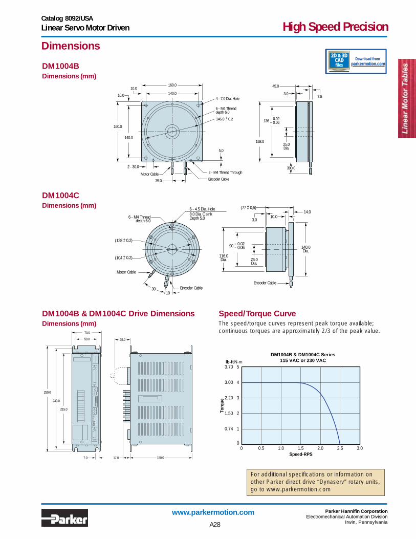
DM 1004 Direct Drive Rotary Tables
Maximum velocity: 2.5 revs per secondAxial and radial run-out of 0.01 mmLoad capacity of 350 kg (770 lb.)Positional repeatability of 3 arc-sec.Faster settling time than a traditionalservo motor and speed reducer systemSmooth rotation at slow speedsAbility to operate in a position, speed or torquecontrol modeBuilt-in test mode simplifies optimum tuningClass 10 cleanroom option
Options:• Line filter for CE installations
• Interface cable for use withParker motion controllers.
• Class 10 CleanroomPreparation
Parker’s DM 1004 is a high performance direct drive rotaryservo system which provides high accuracy and torque withoutthe need of speed reducers. It consists of a brushless directdrive motor, a cross roller support bearing system, an integraloptical encoder, a microprocessor-based drive, power supply,and a 10-foot motor-to-drive cable.
*Drive weight is 4 lb (1.8 kg). **Static loads should be derated as shown
under the following conditions:smooth rotary motion:1/3intermittent press loading:1/5repetitive shock loads:1/10
The highly efficient direct drive brushless motor designeliminates the need for a gear drive or other mechanical drivetrain. The result is long life, maintenance free operation. Thecross roller bearing design can support up to 350 kg (770 lb) ofcompression load and 3,3 kg-m (24.4 ft-lb) of overhung load.
Features
SpecificationsUnits
PerformancePeak torque ft-lbs (N-M) 3 (4) 3 (4)Rated speed 115 VAC rps 2.5 2.5
230 VAC rps 2.5 2.5Static axial load**(max)
Compression lbs (kg) 440 (200) 770 (350)Tension lbs (kg) 154 (70) 770 (350)
Static overhung load** ft-lb (kg-m) 20 (2.7) 24.4 (3.3)Rotor inertia oz-in2 x 102 (kgm2 x 10-3) 3.01 (5.5) 1.37 (2.5)Steps/rev (max) 655,360 655,360Motor weight* lbs (kg) 6.6 (3) 6.6 (3)Repeatability 3 arc-sec (0.00139°)Accuracy ±60 arc-sec (0.0167°) standard
±20 arc-sec (0.00556°) (version available)Max. stepping rate 1,572,000 steps/secPowerVolts 115 VAC 1-phase, or 230 VAC 1-phase, 50/60HzRange +10% to -15%Current 5 amps max.Encoder output 400 kHz max.InputsCommand interface Low going low pulse,
Step input 8.5Direction Logic high = CW rotation
Logic high = CCW rotationAnalog input ±10V velocity signal;
±8V torque signalOutputs A/B encoder output 393 kHz max.Encoder output Z-channel – 124 pulses/rev
DM1004B DM1004C
A27
Catalog 8092/USALinear Servo Motor Driven High Speed Precision
www.parkermotion.com Parker Hannifin CorporationElectromechanical Automation Division
Irwin, Pennsylvania
0
1
DM1004B & DM1004C Series115 VAC or 230 VAC
Speed-RPS
Torq
ue
0
0.74
lb-ftN-m
21.50
32.20
43.00
53.70
0.5 1.0 1.5 2.0 2.5 3.0
35.0
70.0
50.0
215.0
239.0
250.0
150.017.07.0
25.0Dia.
116.0Dia.
140.0Dia.
14.0(77 0,5)+-
10.03.0
Encoder Cable
Motor Cable
30 10
8.0 Dia. C'sinkDepth 5.06 - M4 Thread
depth 6.0
(128 0.2)+-
(104 0.2)+-
6 - 4.5 Dia. Hole
90 - 0.02- 0.06
Encoder Cable
160.0
140.0
140.0
160.0
3.07.5
45.0
25.0Dia.
35.0
5,0
10.0
4 - 7.0 Dia. Hole
6 - M4 Threaddepth 6.0
Motor Cable
10.0
2 - 30.02 - M4 Thread Through
300.0
136 - 0.02- 0.06
158.0
146.0 0.2+-
Encoder Cable
Dimensions
DM1004BDimensions (mm)
DM1004CDimensions (mm)
DM1004B & DM1004C Drive DimensionsDimensions (mm)
Speed/Torque CurveThe speed/torque curves represent peak torque available;continuous torques are approximately 2/3 of the peak value.
For additional specifications or information onother Parker direct drive “Dynaserv” rotary units,go to www.parkermotion.com
A28
2D & 3DCADfiles parkermotion.com
Download from