Embed Size (px)
Citation preview

64

65
Linear Systems
Fran
ke P
ower
FrankeRobust
LinearTables/Modules
Page
Acc
esso
ries
Fran
ke D
ynam
icTechnicalInformation
Franke DynamicTypeFDA Standard 78–79TypeFDB Lowcost 80–81TypeFDC Non-corrosive 82–83TypeFDD Non-magnetic 84–85TypeFDE Lubricant-free 86–87TypeFDG Non-corrosivelowcost 88–89TypeFDH Highdynamic 90–91
Franke Power TypeFPA Standard 92–93
Franke Robust TypeFRA Standard 94–95
Linear Tables/Modules FTB SpindleDrive 96–97FTC Spindle/BeltDrive 98–99FTD BeltDrive 100–101FTH LinearMotorDrive 102–105
Accessories Guides 106–107Modules 108–109
Technical InformationFranke Dynamic 110 – 112Franke Power 113 – 114FrankeRobust 115–116LinearTables/Modules 117–119
Overview, Examples of Use, Advantages/Characteristics 66 – 77

66
Linear Systems at a Glance
Components
RollerGuide Franke Dynamic
•Steelraceways
•Needlebearing
rollers
More on page
FDA Standard
Type
Sizes (mm)Standard
Special
12 – 45
Rail length (mm)one-piece
Travelling speedVmax(m/s)
Acceleration(m/s2)
Use • Forhighloads
in all applications
Advantages
Options
•Steelraceways
•Ballbearingrollers
FDB Lowcost
12 – 45
•Forlowloads
in all applications
•Non-corrosive
raceways
•Needlebearingnon-
corrosiverollers
FDC Non-corrosive
15 – 45
• Formedium
loads in moist
oraggressive
environment
•Non-magnetic
raceways
•Needlebearing
rollers
FDD Non-magnetic
25
•Forlightloadsin
magnetic fields or
radiation rooms
•Steelraceways
•Lubricant-free
rollers
FDE Lubricant-free
12 – 45
•Formediumloads
underextremely
hygienic
conditions
• Aluminiumbodymaterialforcassettes,rollershoesandguideraceways
•Plasticwiperwithfeltinsertonbothfrontsidesofthecassettesorrollershoes
10
40
10
40
10
40
2
10
1
10
4000
4000 4000 4000 4000
• Easierandquieterrunningthankstolarge-sizerollers
•Fastresponsebehaviour
• Nostick-slipeffect
•Slideresistancecanbeadjustedupanddown
•Aluminiumbodymaterialsharmoniseperfectlywithaluminiumcarrierprofilesandfacilitatedesign
of lighter constructions
•Highprecision
•Highloadcapacity
•Reasonableprice •Corrosion-
resistant
•Non-magnetic
materials
•Lubricant-free
and clean
•Specialguideprofiles
•Surfacecoatingoftheracewaysandcassettes
•Customer-specificconnectionborings
•Metalwipers
•Bellowcovers
•Extendedcassettesandrollershoesforhigherloads
•Connectionsforcentrallubrication
•Individualdesignofthecassettes(e.g.withspindleacceptanceorconnectionofmeasuringsystems)
•High-loadracewaysforusewithlinearmotors
•Sizesandspecialshapesforseriesproductionatcustomer’srequest
•Canbecontinuouslycoupledforlongerstroke
78 – 79 80 – 81 82 – 83 84 – 85 86 – 87

67
FDH Highdynamic
RecirculatingRollers Franke Power
•Aluminiumbodymaterial
•Steelraceways
•2rowsofrecirculatingrollers,
arrangedat90°angles
•Plasticwiper
•Lubricatingnipple
FPA Standard
FRA Standard
•Aluminiumbodymaterial
•Steelraceways
•1rowofrecirculatingballs,
ballswithdividers
•Feltwiper
25 06 – 13
4000
continuously coupled
4000
continuously coupled
3
40
3
30
•Forhighloadsand
moment loading in
heavyloadoperation
•Forapplicationswiththe
highest loads in harsh
environments
•Highstiffness
•Highloadcapacity
•Highmomentloadrating
•All-roundsealing
•Relubricationpossiblevia
funnel-typelubricatingnipple
•Lubricationconnection
possible on 4 sides
•Highloadrating
•Highlifetime
•Robustalsoundersevere
conditions
•Shockandimpact-
resistant
•Highstiffness
•Non-corrosiveornon-
magnetic raceways
•Boreshapeto
specifications
FTB, FTC, FTD, FTH
• Lineartables/modules
with spindle, belt or
linearmotordrive,motors,
CNCcontrols
•IntegratedFrankeLinear
Systems
15 – 35
7000
–
10
100
•Forautomation,measuring
and testing applications,
recirculating, processing,
mounting
•Freechoiceof
motorisation
• Highestdynamic
•Compactdimensions
•Linearmotormodulewith
wear-freedrive
•Completemulti-axle
systems
•Mountingangle
•Measuringsystems
•Specialsizingandbore
shapesavailableforseries
production
• Niroversion
SystemsRecirculatingBallGuide Franke Robust
•Non-corrosive
raceways
•Ballbearingnon-
corrosiverollers
FDG Non-corrosivelow cost
12 – 45
•Forlowloadsin
moistoraggressive
environment
•Steelraceways
•2-rowbearing
rollers
25 – 45
•Forhighloads
and high
accelerations
•Slideresistancesetex
works
•Cassetteprefittedon
raceway
10
40
10
40
4000 4000
• Easierandquieterrunningthankstolarge-sizerollers
•Fastresponsebehaviour
• Nostick-slipeffect
•Slideresistancecanbeadjustedupanddown
•Aluminiumbodymaterialsharmoniseperfectlywithaluminiumcarrierprofilesandfacilitatedesign
of lighter constructions
•Corrosion-resistant
•Reasonableprice
•Fastresponse
behaviour
92 – 93 94 – 95 96 – 10588 – 89 90 – 91
NEWNEW

68
Precisex-raysneedthemovementofthelightunittobecompletelyvibration-free.Therefore,therollerguideusedmusthavesmoothandsilentrunning.TheFrankeDynamicAluminiumRollerGuidefulfilsthisdemandperfectly.
Linear Systems in Practice
The Franke principle of the guided roller guarantees easy and silent running, even at high speeds. These factors are essential for smooth production in many industries. Therefore, Franke Linear Systems are also used in the most diverse industrial sectors – for example in medical technology, the food industry, for machine and plant engineering or in the handling sector.
In Medical Technology: Dental X-Ray Equipment
The Features:• TheFrankeDynamicAluminiumRollerGuidehaslifetime
lubrication.•Sealedrollerspreventthelubricantescaping.•Theguide’srunningissilent,smoothandeven.•Preloadingthecassetteensuresvibration-freemovement
of the secondary light.
In the Packing Industry: Bakery Machinery
Afast,cleanandmaintenance-freelinearsystemisrequired inapackingmachineforbakingmixes.Tworetractableaxlesmust be able to run simultaneously on the longitudinal module. The high dynamic of the guide results in correspondingly high cycle times when packing.
The Features:• Thesystemofembeddedracewaysfacilitatestheuseoflight-weight,extrudedaluminiumprofilesfortheguiderails,themagnetsofthestatoraredirectlyintegrated; the motor rests in an aluminum housing.
• Thedirectdrivefacilitatesfastpositioningthatisfree from clearance.
• Theguideachievesmovementspeedsof6m/sandacceleration of up to 100 m/s².
• Sealedrollerspreventthelubricantescaping.

69
In the Food Industry: Cheese Production
Incheeseproductionthefood-safeFrankeDynamicAluminiumRollerGuideprovidestheverticalmovement ofagripperforwheelsofcheese.Inthisapplicationitisimportantthattherollerguideisinsensitivetowheyandaggressivecleaningagents.
The Features:• Theguideisinsensitivetomoisture.•Itsrunningiseasyandsilent,thedrivepowerislow.•Nomaintenanceandlubricationforthewholelifetime
are guaranteed.•Anintegratedwiperfulfilsthespecifichygiene
requirements for food production. •Theproductisavailableinalubricant-freeversion
on request.
A bag forming, filling and sealing machine works at high speeds.Ithasstrokelengthsof1500to2100mm,theaverageserviceperformanceis30000kilometersayear.TheFrankeDynamicAluminiumRollerGuideusedmustberesistanttotheaggressiveenvironmentalconditions,suchassalt,sugarand splash water.
In the Packing Industry: Bag Former/Filler
The Features:• TheFrankeDynamicAluminiumRollerGuideisina
position to realise speeds up to 10 m/s.•Severalguidescanbecoupledforanylengthofstroke
desired.•Agoodlifetimeandserviceperformanceareachieved
through central lubrication of the cassette.

70
Linear Systems in Practice
In the Handling Sector: High Speed Camera Guiding
TheFrankeDynamicAluminiumRollerGuidemovesthehighspeed camera for a film printing machine. A results check is performedduringtheprintingprocessbycameraorvideo.As films of different widths are printed, the camera must be easy to position.
The Features:• TheFrankeDynamicAluminiumRollerGuidehassmooth,evenrunning.
•Itweighsverylittleasthebodymaterialoftherailisaluminium.
•Specialboringsguaranteeconnectiontothepathmeasuring system.
In Plant Engineering: Packaging Machines
TheFrankeDynamicAluminiumRollerGuideisalsoused onpackagingmachineryformattresses.Inadditiontocleanliness, the mobile function of the guide unit must be ensured,toavoidsoilingthemattresses.
The Features:• TheFrankeDynamicAluminiumRollerGuideis maintenance-freeandrequiresnorelubrication.
•Nolubricantcanescapefromtheencapsulatedrollers.•Theguideisavailableinacompletelylubricant-free
design on request.

71
TheFrankePowerAluminiumRecirculatingRollerGuideisusedformachinesthatprocessandpackcoiledgoods.Itensures that cables, hoses or steel ropes are coiled on rings or empty spools, measured to length and cut.
In Machinery: Ring and Drum Coilers
The Features:• TheFrankePowerAluminiumRollerGuidehashighload-capacityandstiffness.
•Thecassettesarecompletelysealedandarealsosuitablefor harsh conditions.
•Integratedmetalwiperskeeptheracewaysclean.
In Machinery: Handling System
Different processing centres are coupled together in this machinethroughlargeportals.Workpiecesareprocessedwithhighacceleration.TheFrankeRobustAluminiumRecirculatingBallGuideisusedinthetransferline.TherecirculatingballsystemoftypeFRA10andFRA13harmon-ises perfectly with the substructure of aluminium profiles.
The Features:•Transferspeedsofupto3m/sandaccelerationsofupto30m/s²areachieved.
•TheFrankeRobustAluminiumRecirculatingBallGuidesusedhaveahighlifetime,eveninharshandverydirtyconditions.
•Tolerancesandunevennessinthesubstructurecanbeequalisedtoacertainextent.

72
The Characteristics:
Cassettes and Roller ShoesThecassetteoftheFrankeDynamicAluminiumRollerGuidehasaluminium body material with needle or ball bearing rollers of steelorstainlesssteel.Specialcoverdiscsontherollersealthebearing to the outside.
EightrollersinO-formationguaranteeanequallyhighloadcapacity from all directions. The rollers are equipped with a groove,whichisadjustedtotheprofileoftheraceway.Thanksto this patented system of guided rollers, the rollers are guided laterally and equally smooth and silent running is guaranteed.
The cassette plate has mounting holes in accordance with international standards. The slide resistance can be adjusted upanddownindividuallyusingasettingscrewontheside. Fivestandardsizesareavailablefromsize12to45.
Inthepairofsinglerailswithrollershoesversionthereisnocassette plate. As a result, the guide width can be selected freely. The roller shoes are screwed directly to the mating structureandfacilitateextremelycompactassemblies.
Threadpiecesforone-sidedadjustabilityoftheslideresistanceare supplied and can be integrated.
Aluminium body material for cassettes and guide rails
Profiled raceways
Guidedrollerswith grooveinO-formation
Franke Dynamic Aluminium Roller Guide – Advantages and CharacteristicsType FDA – FDH

73
Wipers Thebearingsoftherollersaresealedandhavelifetime lubrication. Thanks to the standard felt wiper, lasting protection of the guide system from soiling is guaranteed.
Metalwipersareincludedasaccessories,whichare particularly recommended for coarse dirt such as chippings orsawdustandkeeptheracewayclean(seeaccessories page 106).
Lubricant-freecassettesandrollershoesareavailableastypeFDE.Theyarealsosuitableforhygienicallysensitivesectors, forexamplethefoodindustryormedicaltechnology.
Guide RailsTheracewaysofspringsteel,non-corrosiveornon-magneticsteelareintegratedinthealuminiumprofile.TheO-formationguarantees high load capacity from all directions. The profile of the rollers is adjusted to the raceway and guarantees permanently precise and smooth running.
Theguiderailsareavailableinonepieceuptoalengthoffourmeters. They can be continuously coupled for longer strokes. we can supply rail profiles specially tailored to your design on request.
Frankeprecisionracewaysofspringsteel,non-corrosiveornon-magneticsteelcanbeintegratedintoavarietyofaluminiumprofiles.Wecansupplyyourchosenprofilecompletewithintegrated raceways in series production.
Wealsoofferspeciallyhardenedracewaysfortheheaviestloads.
The Advantages:
• Lowweightthankstoaluminiumbodymaterial•SilentandeasyrunningthankstothepatentedGuided Roller®
•Maintenance-freeandclean•O-formationforequalloadsfromalldirections•Hightraversespeedandacceleration•Numerousvariationsforalmostanyapplication•Customer-specificsolutionsifseriesneeded

74
Franke DynamicAluminium Roller Guide – Numerous Possibilities
Further Possibilities:
DesignFor series production it is possible to adjust the shape and design of the cassettes, roller shoes and guide profiles to your individualapplication.Youwillgettheperfectsolutiontailoredto your requirements.
Adjustment options are:•Shortenedorextendedrollershoes/cassettes•Specialshapes,e.g.forintegrationofdrives•Specialprofilesofguiderailsaccordingtoyourneeds•Individualboreshapesontheguiderails•Fixingfromunderneath
Vacuum/High TemperatureWealsoofferspecialcassettesandrollershoesforapplications invacuums.Theyaredesignedwithfreeboringsandequippedwithlubricantssuitedtohighvacuumsonrequest.
Youcanchoosefromaselectionofspecial,heat-resistantcassettes and roller shoes for applications with radiant heat in thevicinityofheatsources.
Temperaturerangesupto200°Carepossible.
The Different Types:
Type FDA Standard
Type FDB Low cost
Type FDC Non-corrosive
Type FDD Non-magnetic
Type FDE Lubricant-free
Type FDG Non-corrosive low cost
Type FDH High dynamic
Wecanalsosupplyspecialcassettesinspecificdimensions,heat-resistantversionsandvacuum-fitforseriesproduction. Please call us.

75
Clean RoomTheFrankeDynamicAluminiumRollerGuidewasappraised andevaluatedattheInstitutfürProduktionstechnikundAutomatisierung(IPA)attheFraunhoferGesellschaft(FhG) inStuttgartwithregardtoitsoperationinroomswithhigh air purity rates.
Theresult:theFrankeDynamicAluminiumRollerGuideoftypeFDAissuitableforcleanroom-typicalmovementspeedsforuseincleanroomswithairpurityclasses“Class1000”.
Complete Systems TheFrankeDynamicAluminiumRollerGuidesarealsoused inourcompletesystemsoflinearaxis,drive,motorisation andcontrol.FrankeLinearModulesandLinearTablesusetheassetsofLinearSystemstobuild-upcompletemovingunits.
ToothedbeltgearLinearModulesareavailableuptoastrokelength of 7000 mm. The integrated Franke Dynamic Aluminium RollerGuideprovideshighdynamicmovementsandeasyandsilent running.
Itisextremelysuitableforthelistedloadingconditions.Thetrendsoftheresults(e.g.particleemissionsonincreaseofthemovedmass)allowustostatethatasuitabilityfor“Class1000”isalsoachievedforhigherloads.

76
The Advantages:
•Highloadcapacityandstiffness•Connectingdimensionscompatible
with international standards•Integratedmetalwipers•All-roundsealing
Integratedwiperandlubricating nipple
Aluminium body material for the cassette and rail
RollersinO-formation
Profiled raceways
Franke PowerAluminium Recirculating Roller GuideType FPA
The Characteristics:
CassetteThecassetteoftheFrankePowerAluminiumRecirculatingRollerGuideismadefromspecialaluminiumwithfixingbores in accordance with international standards and, therefore, is interchangeable with products from many manufacturers. Wear-resistantplasticsealsprovideall-roundsealingforthecassette. The additional frontal metal wipers are adjusted to the rail contour and protect the guide system from coarse impurities.
Therecirculatingrollersin90°-formationguaranteeeven, highloadcapacityandloadingfromeverydirection.Eachcassette has a lubrication nipple, which can be attached to one of the four front ends. A defined slide resistance ensures alignmentontheguiderails.Itissuppliedwithapreloadclasswith light preload. The guides can be mounted on unprocessed surfaces without impairing the lifetime. The inner elasticity of theRecirculatingRollerGuideisensuredbyasystempatented by Franke.
Guide Rails Racewaysofspringsteel,non-corrosiveornon-magnetic steelareintegratedinthealuminiumprofile.HighloadcapacityfromalldirectionsisguaranteedbytheO-formation.Theprofileof the rollers is adjusted to the raceway and ensures precise and easy running permanently.
The guide rails can be supplied as one piece up to a length of four meters and can be coupled together endlessly for longer strokes.Wecansupplyboreshapesspeciallytailoredtoyourdesign on request.

77
FTH 25 FTH 35
FTH DriveAluminium Linear Motor ModuleType FTH
The Advantages:
• Lowspacerequirement(height)•Greaterclosenessofthesystem (nodouble-trackrailset-up), so simpler to clean and less risk of contamination
•Reducedcomponents
The Characteristics:
Roller Shoes and Guide Rails BuildingontheprovenFrankeAluminiumRollerGuide,theLinearMotorModuleFTHimpresseswithitslowweightandcompactdimensions.Therollershoeshavebeenspeciallydesigned for high loads. The rail profile was designed so that thestatorcouldbeintegrated.Thissavesheightandweight.The modular design of the system enables numerous adjust-mentsaccordingtotheindividualuse.
Multi-Module SystemsInadditiontocustomer-specificmatingandprofiledimensions,severalslidescanbemovedindependentlyofoneanotherpermodule.Completemulti-modulesystemsusinganglesandadapterplatesisalsopossible.WecansupplytheLinearMotorModulewithallwiringandtailoredtoyourdesiredcontrolmodeon request.
Conventional linear motor module
Slideelement
Magnetictrack
Guidesystem
Aluminium profile
Motor
Franke FTH Drive
Slideelement
Motor
Magnetictrack
Guidesystem
Aluminium profile
The Franke FTH Drive in comparison to conventional products
Aluminium slide to house the motor
Inlaidsteelraceways
Magnetictrack,integratedin the rail profile
Covertoprotectthe magnetic track
Rollershoeswithcrosswise rollers for the highest dynamic
Motor
Integrated measuring system
Aluminium profile to house the raceway and magnetic track
NEWNEW

78
Fran
ke D
ynam
ic
Dimensions
Franke DynamicType FDA
AluminiumRollerGuideStandard
Size Dimensions mm A L H B1 B2 D D1 D2 E1 E2 H1 H2 H3 H4 L2 L3 T T1
12 37 64 19 12.0 12.50 3.4 6 M 4 25 30 14.7 4.0 1.4 5.5 10 40 5.5 8
15 47 78 24 15.5 15.75 4.5 8 M 5 30 38 18.7 5.0 2.0 8.0 10 60 6.0 10
20 63 92 30 21.0 21.00 5.5 10 M 6 40 53 22.6 7.0 2.0 11.0 10 60 8.0 12
25 70 98 36 23.0 23.50 6.6 11 M 8 45 57 27.0 8.5 2.5 13.0 10 60 10.0 16
35 100 135 48 32.0 34.00 9.0 15 M10 62 82 37.0 10.5 3.5 20.0 12 80 11.5 20
45 120 165 60 45.0 37.50 11.0 18 M12 80 100 46.0 13.5 4.0 22.0 16 105 14.5 24
Size Load ratings Moment load ratings* cassette Weight N Nm kg C Co Mocx Mcx Mocy/Mocz Mcy/Mcz Cassette rail/m
12 2800 3000 27 25 43 40 0.1 0.4
15 4200 3400 37 45 58 72 0.2 0.8
20 5400 5400 76 76 111 111 0.4 0.9
25 9000 10100 158 142 222 198 0.5 1.8
35 12500 18000 423 294 559 388 1.4 3.2
45 21200 25900 827 678 983 806 2.5 5.5
Load ratings, weight
*There is more information on moment load ratings on page 110/111.
Order no. Order key
Cassette Double rail
84494A 84396A 84441A 84363A 84364A 84365A
Order numbers
**Guiderailsupto4000mmononepiece.Longerstrokesarecoupled.
e.g. FDA 25 D 1500
Type
Size
Lengthinmm**
Double rail
Cassette + double rail

79
Fran
ke D
ynam
ic
Dimensions
Size Dimensions mm B5 H5 B3 B4 D3 D4 D5 E3 E4 E5 E6 E7 E8 E9 H6 T3 a b
12 24.4 15.0 12.00 11.9 M3 8 3 3.4 29 57 9.7 3.4 5.5 4.9 4 6.0 4.5 9.5
15 30.9 19.0 15.25 15.2 M4 10 4 4.4 34 68 12.4 4.9 7.0 5.9 5 7.5 5.0 12.5
20 40.9 23.0 20.00 20.4 M5 10 4 4.9 42 80 16.9 5.9 9.5 5.9 5 8.0 7.5 16.0
25 48.4 27.5 25.00 22.9 M5 14 6 6.4 48 84 19.4 7.4 12.0 8.9 7 5.0 10.5 17.5
35 68.9 37.5 35.00 32.9 M6 14 6 8.9 67 117 28.4 8.9 17.0 8.9 7 7.5 12.5 26.0
45 82.4 46.5 45.00 36.4 M8 14 6 9.9 83 146 30.9 9.9 22.0 8.9 7 9.5 15.5 31.0
Size Load ratings Moment load ratings* RSP Weight N Nm kg C Co Mocx Mcx Mocy/Mocz Mcy/Mcz RSP rail/m
12 2800 3000 1.5(B+30.3) 1.4(B+ 30.3) 43 40 0.07 0.4
15 4200 3400 1.7(B+36.5) 2.1(B+ 36.5) 58 72 0.12 0.8
20 5400 5400 2.7(B+47.0) 2.7(B+ 47.0) 111 111 0.23 1.0
25 9000 10100 5.0(B+58.4) 4.5(B+ 58.4) 222 198 0.34 1.9
35 12500 18000 9.0(B+85.0) 6.3(B+ 85.0) 559 388 0.99 3.5
45 21200 25900 12.9(B+109.0) 10.6(B+109.0) 983 806 1.79 5.6
Load ratings, weight
*There is more information on moment load ratings on page 110/111. **Guiderailsupto4000mmononepiece.Longerstrokesarecoupled.
Order no. Order key
RSP Singlerailpair
84495A 84395A 84442A 84367A 84368A 84369A
Order numbers
e.g. FDA 25 E 1500
Pair of roller shoes + single rail pairs
Materials
Body material Rollers Wipers
Standard High-strength, Antifriction Plasticplate anodized bearingsteel withfeltwiper aluminium
Type
Size
Lengthinmm**
Singlerail

80
Franke DynamicType FDB
AluminiumRollerGuideLowcost
Fran
ke D
ynam
ic
Size Dimensions mm A L H B1 B2 D D1 D2 E1 E2 H1 H2 H3 H4 L2 L3 T T1
12 37 64 19 12.0 12.50 3.4 6 M 4 25 30 14.7 4.0 1.4 5.5 10 40 5.5 8
15 47 78 24 15.5 15.75 4.5 8 M 5 30 38 18.7 5.0 2.0 8.0 10 60 6.0 10
20 63 92 30 21.0 21.00 5.5 10 M 6 40 53 22.6 7.0 2.0 11.0 10 60 8.0 12
25 70 98 36 23.0 23.50 6.6 11 M 8 45 57 27.0 8.5 2.5 13.0 10 60 10.0 16
35 100 135 48 32.0 34.00 9.0 15 M10 62 82 37.0 10.5 3.5 20.0 12 80 11.5 20
45 120 165 60 45.0 37.50 11.0 18 M12 80 100 46.0 13.5 4.0 22.0 16 105 14.5 24
Size Load ratings Moment load ratings* cassette Weight N Nm kg C Co Mocx Mcx Mocy/Mocz Mcy/Mcz Cassette rail/m
12 620 170 1.6 5.7 2.4 8.9 0.1 0.4
15 700 230 2.5 7.5 4.0 12.0 0.2 0.8
20 940 300 4.0 13.0 6.0 19.0 0.4 0.9
25 1500 700 11.0 23.0 15.0 32.0 0.5 1.8
35 3100 1400 32.0 72.0 42.0 95.0 1.4 3.2
45 6300 2700 86.0 200.0 103.0 238.0 2.5 5.5
*There is more information on moment load ratings on page 110/111.
Order no. Order key
Cassette Double rail
84494L 84396L 84441L 84363L 84364L 84365L
**Guiderailsupto4000mmononepiece.Longerstrokesarecoupled.
e.g. FDA 25 D 1500
Dimensions
Load ratings, weight Order numbers
Cassette + double rail
Type
Size
Lengthinmm**
Double rail

81
Fran
ke D
ynam
ic
Size Dimensions mm B5 H5 B3 B4 D3 D4 D5 E3 E4 E5 E6 E7 E8 E9 H6 T3 a b
12 24.4 15.0 12.00 11.9 M3 8 3 3.4 29 57 9.7 3.4 5.5 4.9 4 6.0 4.5 9.5
15 30.9 19.0 15.25 15.2 M4 10 4 4.4 34 68 12.4 4.9 7.0 5.9 5 7.5 5.0 12.5
20 40.9 23.0 20.00 20.4 M5 10 4 4.9 42 80 16.9 5.9 9.5 5.9 5 8.0 7.5 16.0
25 48.4 27.5 25.00 22.9 M5 14 6 6.4 48 84 19.4 7.4 12.0 8.9 7 5.0 10.5 17.5
35 68.9 37.5 35.00 32.9 M6 14 6 8.9 67 117 28.4 8.9 17.0 8.9 7 7.5 12.5 26.0
45 82.4 46.5 45.00 36.4 M8 14 6 9.9 83 146 30.9 9.9 22.0 8.9 7 9.5 15.5 31.0
Size Load ratings Moment load ratings* RSP Weight N Nm kg C Co Mocx Mcx Mocy/Mocz Mcy/Mcz RSP rail/m
12 620 170 0.08(B+30.3) 0.30(B+ 30.3) 2.4 8.9 0.07 0.4
15 700 230 0.10(B+36.5) 0.35(B+ 36.5) 4.0 12.0 0.12 0.8
20 940 300 0.15(B+47.0) 0.50(B+ 47.0) 6.0 19.0 0.23 1.0
25 1500 700 0.35(B+58.4) 0.70(B+ 58.4) 15.0 32.0 0.34 1.9
35 3100 1400 0.70(B+85.0) 1.50(B+ 85.0) 42.0 95.0 0.99 3.5
45 6300 2700 1.40(B+109.0) 3.10(B+109.0) 103.0 238.0 1.79 5.6
*There is more information on moment load ratings on page 110/111. **Guiderailsupto4000mmononepiece.Longerstrokesarecoupled.
Order no. Order key
RSP Singlerailpair
84495L 84395L 84442L 84367L 84368L 84369L
e.g. FDA 25 E 1500
Dimensions
Load ratings, weight Order numbers
Pair of roller shoes + single rail pairs
Materials
Body material Rollers Wipers
Standard High-strength, Antifriction Plasticplate anodized bearingsteel withfeltwiper aluminium
Type
Size
Lengthinmm**
Singlerail

82
Franke DynamicType FDC
AluminiumRollerGuideNon-corrosive
Fran
ke D
ynam
ic
Size Dimensions mm A L H B1 B2 D D1 D2 E1 E2 H1 H2 H3 H4 L2 L3 T T1
12 37 64 19 12.0 12.50 3.4 6 M 4 25 30 14.7 4.0 1.4 5.5 10 40 5.5 8
15 47 78 24 15.5 15.75 4.5 8 M 5 30 38 18.7 5.0 2.0 8.0 10 60 6.0 10
20 63 92 30 21.0 21.00 5.5 10 M 6 40 53 22.6 7.0 2.0 11.0 10 60 8.0 12
25 70 98 36 23.0 23.50 6.6 11 M 8 45 57 27.0 8.5 2.5 13.0 10 60 10.0 16
35 100 135 48 32.0 34.00 9.0 15 M10 62 82 37.0 10.5 3.5 20.0 12 80 11.5 20
45 120 165 60 45.0 37.50 11.0 18 M12 80 100 46.0 13.5 4.0 22.0 16 105 14.5 24
Size Load ratings Moment load ratings* cassette Weight N Nm kg C Co Mocx Mcx Mocy/Mocz Mcy/Mcz Cassette rail/m
12 1100 1200 11 10 17 16 0.1 0.4
15 2700 3000 33 29 52 46 0.2 0.8
20 4300 5000 71 61 103 89 0.4 0.9
25 5800 8300 132 92 184 128 0.5 1.8
35 10000 14500 343 237 452 312 1.4 3.2
45 17000 20400 651 542 774 645 2.5 5.5
*There is more information on moment load ratings on page 110/111.
Order no. Order key
Cassette Double rail
84494AN 84396AN 84441AN 84363AN 84364AN 84365AN
**Guiderailsupto4000mmononepiece.Longerstrokesarecoupled.
e.g. FDC 25 D 1500
Dimensions
Load ratings, weight Order numbers
Cassette + double rail
Type
Size
Lengthinmm**
Double rail

83
Fran
ke D
ynam
ic
Size Dimensions mm B5 H5 B3 B4 D3 D4 D5 E3 E4 E5 E6 E7 E8 E9 H6 T3 a b
12 24.4 15.0 12.00 11.9 M3 8 3 3.4 29 57 9.7 3.4 5.5 4.9 4 6.0 4.5 9.5
15 30.9 19.0 15.25 15.2 M4 10 4 4.4 34 68 12.4 4.9 7.0 5.9 5 7.5 5.0 12.5
20 40.9 23.0 20.00 20.4 M5 10 4 4.9 42 80 16.9 5.9 9.5 5.9 5 8.0 7.5 16.0
25 48.4 27.5 25.00 22.9 M5 14 6 6.4 48 84 19.4 7.4 12.0 8.9 7 5.0 10.5 17.5
35 68.9 37.5 35.00 32.9 M6 14 6 8.9 67 117 28.4 8.9 17.0 8.9 7 7.5 12.5 26.0
45 82.4 46.5 45.00 36.4 M8 14 6 9.9 83 146 30.9 9.9 22.0 8.9 7 9.5 15.5 31.0
Size Load ratings Moment load ratings* RSP Weight N Nm kg C Co Mocx Mcx Mocy/Mocz Mcy/Mcz RSP rail/m
12 1100 1200 0.6(B+30.3) 0.6(B+ 30.3) 17 16 0.07 0.4
15 2700 3000 1.5(B+36.5) 1.4(B+ 36.5) 52 46 0.12 0.8
20 4300 5000 2.5(B+47.0) 2.2(B+ 47.0) 103 89 0.23 1.0
25 5800 8300 4.2(B+58.4) 2.9(B+ 58.4) 184 128 0.34 1.9
35 10000 14500 7.3(B+85.0) 5.0(B+ 85.0) 452 312 0.99 3.5
45 17000 20400 10.2(B+109.0) 8.5(B+109.0) 774 645 1.79 5.6
*There is more information on moment load ratings on page 110/111. **Guiderailsupto4000mmononepiece.Longerstrokesarecoupled.
Order no. Order key
RSP Singlerailpair
84495AN 84395AN 84442AN 84367AN 84368AN 84369AN
e.g. FDC 25 E 1500
Materials
Body material Rollers Wipers
Standard High-strength, Antifriction Plasticplate anodized bearingsteel withfeltwiper aluminium
Dimensions
Load ratings, weight Order numbers
Pair of roller shoes + single rail pairs
Type
Size
Lengthinmm**
Singlerail

84
Franke DynamicType FDD
AluminiumRollerGuideNon-magnetic
Fran
ke D
ynam
ic
Dimensions
Size Dimensions mm A L H B1 B2 D D1 D2 E1 E2 H1 H2 H3 H4 L2 L3 T T1
25 70 98 36 23.0 23.50 6.6 11 M 8 45 57 27.0 8.5 2.5 13.0 10 60 10.0 16
Size Load ratings Moment load ratings* cassette Weight N Nm kg C Co Mocx Mcx Mocy/Mocz Mcy/Mcz Cassette rail/m
25 1200 1600 25 18 35 25 0.5 1.8
Order no. Order key
Cassette Double rail
84363P e.g. FDD 25 D 1500
Cassette + double rail
Load ratings, weight Order numbers
*There is more information on moment load ratings on page 110/111. **Guiderailsupto4000mmononepiece.Longerstrokesarecoupled.
Type
Size
Lengthinmm**
Double rail

85
Fran
ke D
ynam
ic
Dimensions
Size Dimensions mm B5 H5 B3 B4 D3 D4 D5 E3 E4 E5 E6 E7 E8 E9 H6 T3 a b
25 48.4 27.5 25.00 22.9 M5 14 6 6.4 48 84 19.4 7.4 12.0 8.9 7 5.0 10.5 17.5
Size Load ratings Moment load ratings* RSP Weight N Nm kg C Co Mocx Mcx Mocy/Mocz Mcy/Mcz RSP rail/m
25 1200 1600 0.8(B+58.4) 0.6(B+58.4) 35 25 0.34 1.9
Order no. Order key
RSP Singlerailpair
84367P e.g. FDD 25 E 1500
Materials
Body material Rollers Wipers
Standard High-strength, Antifriction Plasticplate anodized bearingsteel withfeltwiper aluminium
Pair of roller shoes + single rail pairs
Load ratings, weight Order numbers
*There is more information on moment load ratings on page 110/111. **Guiderailsupto4000mmononepiece.Longerstrokesarecoupled.
Type
Size
Lengthinmm**
Singlerail

86
Franke DynamicType FDE
AluminiumRollerGuideLubricant-free
Fran
ke D
ynam
ic
Size Dimensions mm A L H B1 B2 D D1 D2 E1 E2 H1 H2 H3 H4 L2 L3 T T1
12 37 64 19 12.0 12.50 3.4 6 M 4 25 30 14.7 4.0 1.4 5.5 10 40 5.5 8
15 47 78 24 15.5 15.75 4.5 8 M 5 30 38 18.7 5.0 2.0 8.0 10 60 6.0 10
20 63 92 30 21.0 21.00 5.5 10 M 6 40 53 22.6 7.0 2.0 11.0 10 60 8.0 12
25 70 98 36 23.0 23.50 6.6 11 M 8 45 57 27.0 8.5 2.5 13.0 10 60 10.0 16
35 100 135 48 32.0 34.00 9.0 15 M10 62 82 37.0 10.5 3.5 20.0 12 80 11.5 20
45 120 165 60 45.0 37.50 11.0 18 M12 80 100 46.0 13.5 4.0 22.0 16 105 14.5 24
Size Load ratings Moment load ratings* cassette Weight N Nm kg C Co Mocx Mcx Mocy/Mocz Mcy/Mcz Cassette rail/m
12 350 400 4 3 6 5 0.1 0.4
15 600 700 8 6 12 10 0.2 0.8
20 700 900 12 9 17 14 0.4 0.9
25 1200 1600 25 18 35 25 0.5 1.8
35 2000 2500 58 44 76 58 1.4 3.2
45 4400 5500 180 140 210 170 2.5 5.5
Order no. Order key
Cassette Double rail
84494T 84396T 84441T 84363T 84364T 84365T
e.g. FDA 25 D 1500
Cassette + double rail
Dimensions
Load ratings, weight Order numbers
*There is more information on moment load ratings on page 110/111. **Guiderailsupto4000mmononepiece.Longerstrokesarecoupled.
Type
Size
Lengthinmm**
Double rail

87
Fran
ke D
ynam
ic
Size Dimensions mm B5 H5 B3 B4 D3 D4 D5 E3 E4 E5 E6 E7 E8 E9 H6 T3 a b
12 24.4 15.0 12.00 11.9 M3 8 3 3.4 29 57 9.7 3.4 5.5 4.9 4 6.0 4.5 9.5
15 30.9 19.0 15.25 15.2 M4 10 4 4.4 34 68 12.4 4.9 7.0 5.9 5 7.5 5.0 12.5
20 40.9 23.0 20.00 20.4 M5 10 4 4.9 42 80 16.9 5.9 9.5 5.9 5 8.0 7.5 16.0
25 48.4 27.5 25.00 22.9 M5 14 6 6.4 48 84 19.4 7.4 12.0 8.9 7 5.0 10.5 17.5
35 68.9 37.5 35.00 32.9 M6 14 6 8.9 67 117 28.4 8.9 17.0 8.9 7 7.5 12.5 26.0
45 82.4 46.5 45.00 36.4 M8 14 6 9.9 83 146 30.9 9.9 22.0 8.9 7 9.5 15.5 31.0
Size Load ratings Moment load ratings* RSP Weight N Nm kg C Co Mocx Mcx Mocy/Mocz Mcy/Mcz RSP rail/m
12 350 400 0.20(B+ 30.3) 0.20(B+ 30.3) 6 5 0.07 0.4
15 600 700 0.35(B+ 36.5) 0.30(B+ 36.5) 12 10 0.12 0.8
20 700 900 0.40(B+ 47.0) 0.33(B+ 47.0) 17 14 0.23 1.0
25 1200 1600 0.80(B+ 58.4) 0.60(B+ 58.4) 35 25 0.34 1.9
35 2000 2500 1.20(B+ 85.0) 0.90(B+ 85.0) 76 58 0.99 3.5
45 4400 5500 2.70(B+109.0) 2.20(B+109.0) 210 170 1.79 5.6
Order no. Order key
RSP Singlerailpair
84495T 84395T 84442T 84367T 84368T 84369T
e.g. FDA 25 E 1500
Materials
Body material Rollers Wipers
Standard High-strength, Antifriction Plasticplate anodized bearingsteel withfeltwiper aluminium
Pair of roller shoes + single rail pairs
Dimensions
Load ratings, weight Order numbers
*There is more information on moment load ratings on page 110/111. **Guiderailsupto4000mmononepiece.Longerstrokesarecoupled.
Type
Size
Lengthinmm**
Singlerail

88
Franke DynamicType FDG
AluminiumRollerGuideNon-corrosivelowcost
Fran
ke D
ynam
ic
Size Dimensions mm A L H B1 B2 D D1 D2 E1 E2 H1 H2 H3 H4 L2 L3 T T1
12 37 64 19 12.0 12.50 3.4 6 M 4 25 30 14.7 4.0 1.4 5.5 10 40 5.5 8
15 47 78 24 15.5 15.75 4.5 8 M 5 30 38 18.7 5.0 2.0 8.0 10 60 6.0 10
20 63 92 30 21.0 21.00 5.5 10 M 6 40 53 22.6 7.0 2.0 11.0 10 60 8.0 12
25 70 98 36 23.0 23.50 6.6 11 M 8 45 57 27.0 8.5 2.5 13.0 10 60 10.0 16
35 100 135 48 32.0 34.00 9.0 15 M10 62 82 37.0 10.5 3.5 20.0 12 80 11.5 20
45 120 165 60 45.0 37.50 11.0 18 M12 80 100 46.0 13.5 4.0 22.0 16 105 14.5 24
Size Load ratings Moment load ratings* cassette Weight N Nm kg C Co Mocx Mcx Mocy/Mocz Mcy/Mcz Cassette rail/m
12 620 170 1.6 5.7 2.4 8.9 0.1 0.4
15 700 230 2.5 7.5 4.0 12.0 0.2 0.8
20 940 300 4.0 13.0 6.0 19.0 0.4 0.9
25 1500 700 11.0 23.0 15.0 32.0 0.5 1.8
35 3100 1400 32.0 72.0 42.0 95.0 1.4 3.2
45 6300 2700 86.0 200.0 103.0 238.0 2.5 5.5
Order no. Order key
Cassette Double rail
84494LN 84396LN 84441LN 84363LN 84364LN 84365LN
e.g. FDC 25 D 1500
Cassette + double rail
Dimensions
Load ratings, weight Order numbers
*There is more information on moment load ratings on page 110/111. **Guiderailsupto4000mmononepiece.Longerstrokesarecoupled.
Type
Size
Lengthinmm**
Double rail

89
Fran
ke D
ynam
ic
Size Dimensions mm B5 H5 B3 B4 D3 D4 D5 E3 E4 E5 E6 E7 E8 E9 H6 T3 a b
12 24.4 15.0 12.00 11.9 M3 8 3 3.4 29 57 9.7 3.4 5.5 4.9 4 6.0 4.5 9.5
15 30.9 19.0 15.25 15.2 M4 10 4 4.4 34 68 12.4 4.9 7.0 5.9 5 7.5 5.0 12.5
20 40.9 23.0 20.00 20.4 M5 10 4 4.9 42 80 16.9 5.9 9.5 5.9 5 8.0 7.5 16.0
25 48.4 27.5 25.00 22.9 M5 14 6 6.4 48 84 19.4 7.4 12.0 8.9 7 5.0 10.5 17.5
35 68.9 37.5 35.00 32.9 M6 14 6 8.9 67 117 28.4 8.9 17.0 8.9 7 7.5 12.5 26.0
45 82.4 46.5 45.00 36.4 M8 14 6 9.9 83 146 30.9 9.9 22.0 8.9 7 9.5 15.5 31.0
Size Load ratings Moment load ratings* RSP Weight N Nm kg C Co Mocx Mcx Mocy/Mocz Mcy/Mcz RSP rail/m
12 620 170 0.08(B+ 30.3) 0.30(B+ 30.3) 2.4 8.9 0.07 0.4
15 700 230 0.10(B+ 36.5) 0.35(B+ 36.5) 4.0 12.0 0.12 0.8
20 940 300 0.15(B+ 47.0) 0.50(B+ 47.0) 6.0 19.0 0.23 1.0
25 1500 700 0.35(B+ 58.4) 0.70(B+ 58.4) 15.0 32.0 0.34 1.9
35 3100 1400 0.70(B+ 85.0) 1.50(B+ 85.0) 42.0 95.0 0.99 3.5
45 6300 2700 1.40(B+109.0) 3.10(B+109.0) 103.0 238.0 1.79 5.6
Order no. Order key
RSP Singlerailpair
84495LN 84395LN 84442LN 84367LN 84368LN 84369LN
e.g. FDC 25 E 1500
Materials
Body material Rollers Wipers
Standard High-strength, Antifriction Plasticplate anodized bearingsteel withfeltwiper aluminium
Pair of roller shoes + single rail pairs
Dimensions
Load ratings, weight Order numbers
*There is more information on moment load ratings on page 110/111. **Guiderailsupto4000mmononepiece.Longerstrokesarecoupled.
Type
Size
Lengthinmm**
Singlerail

90
Franke DynamicType FDH
AluminiumRollerGuideHighdynamic
Fran
ke D
ynam
ic
Dimensions
Size Dimensions mm A L H B1 B2 D D1 D2 E1 E2 H1 H2 H3 H4 L2 L3 T T1
25 70 98 36 23.0 23.50 6.6 11 M 8 45 57 27.0 8.5 2.5 13.0 10 60 10.0 16
35 100 135 48 32.0 34.00 9.0 15 M10 62 82 37.0 10.5 3.5 20.0 12 80 11.5 20
45 120 165 60 45.0 37.50 11.0 18 M12 80 100 46.0 13.5 4.0 22.0 16 105 14.5 24
Size Load ratings Moment load ratings* cassette Weight N Nm kg C Co Mocx Mcx Mocy/Mocz Mcy/Mcz Cassette rail/m
25 7500 3700 58 118 81 165 0.5 1.8
35 13400 8100 189 315 250 416 1.4 3.2
45 24300 14400 461 777 548 924 2.5 5.5
Order no. Order key
Cassette Double rail
84363S 84364S 84365S
e.g. FDA 25 D 1500
Cassette + double rail
Load ratings, weight Order numbers
*There is more information on moment load ratings on page 110/111. **Guiderailsupto4000mmononepiece.Longerstrokesarecoupled.
Type
Size
Lengthinmm**
Double rail

91
Fran
ke D
ynam
ic
Dimensions
Size Dimensions mm B5 H5 B3 B4 D3 D4 D5 E3 E4 E5 E6 E7 E8 E9 H6 T3 a b
25 48.4 27.5 25.00 22.9 M5 14 6 6.4 48 84 19.4 7.4 12.0 8.9 7 5.0 10.5 17.5
35 68.9 37.5 35.00 32.9 M6 14 6 8.9 67 117 28.4 8.9 17.0 8.9 7 7.5 12.5 26.0
45 82.4 46.5 45.00 36.4 M8 14 6 9.9 83 146 30.9 9.9 22.0 8.9 7 9.5 15.5 31.0
Size Load ratings Moment load ratings* RSP Weight N Nm kg C Co Mocx Mcx Mocy/Mocz Mcy/Mcz RSP rail/m
25 7500 3700 1.8(B+ 58.4) 3.7(B+ 58.4) 81 165 0.34 1.9
35 13400 8100 4.0(B+ 85.0) 6.7(B+ 85.0) 250 416 0.99 3.5
45 24300 14400 7.2(B+109.0) 12.2(B+109.0) 548 924 1.79 5.6
Order no. Order key
RSP Singlerailpair
84367S 84368S 84369S
e.g. FDA 25 E 1500
Materials
Body material Rollers Wipers
Standard High-strength, Antifriction Plasticplate anodized bearingsteel withfeltwiper aluminium
Pair of roller shoes + single rail pairs
Load ratings, weight Order numbers
*There is more information on moment load ratings on page 110/111. **Guiderailsupto4000mmononepiece.Longerstrokesarecoupled.
Type
Size
Lengthinmm**
Singlerail

92
Fran
ke P
ower
Franke PowerType FPA
AluminiumRecirculatingRollerGuideStandard
Cassette + double rail

93
Fran
ke P
ower
Dimensions
Size Dimensions mm A L H B1 B2 D D1 D2 D3 E1 E2 E3 H1 H3 H4 L2 L3 L4 T T1 T2 T3 S1 S2
25 70 70 36 23 23.5 6.6 11 M8 M6 45 57 40 27 2.5 10 10 60 102 10 16 8 6 9 6
Size Load ratings Moment load ratings* cassette Weight N Nm kg C Co Mocx Mcx Mocy/Mocz Mcy/Mcz Cassette rail/m
25 23400 25000 392 368 245 230 0.39 1.8
Load ratings, weight
*There is more information on moment load ratings on page 110/111.
Order no. Order key
Cassette Double rail
84042A
Order numbers
**Guiderailsupto4000mmononepiece.Longerstrokesarecoupled.
e.g. FDA 25 D 1500
Type
Size
Lengthinmm**
Double rail
Materials
Body material Rollers Wipers
Standard High-strength, Antifriction Plasticplate anodized bearingsteel withTEEE aluminium wipers

94
Franke RobustType FRA
AluminiumRecirculatingBallGuideStandard
FrankeRobust
Recirculating element + single rail
Type FRA06E / FRA08E Type FRA10E / FRA13E
Lubrication borings
FRA06U / FRA08U with through boring
FRA06U / FRA13U with thread boring
FRA10U / FRA13U with through boring

95
FrankeRobust
Materials
Body material Balls Wipers
Standard High-strength, Antifriction Integrated anodized bearingsteel feltwiper aluminium Steel Zinc diecasting
Dimensions single rail
Size Dimensions mm H B1 B3 B4 B6 B7 D D1 E4 E5 E7 H1 H3 H6 L2 L3 T
FRA06E 16.0 20.0 36.5 44.5 38.0 44.5 5.5 10 24.5 7.0 20.7 16.7 1.0 27.7 25 50 7.0
FRA08E 21.0 26.3 47.3 57.3 48.8 57.3 6.6 11 31.8 8.5 26.0 22.2 1.0 32.5 50 100 8.5
FRA10E 23.8 24.4 51.4 63.0 51.4 62.9 9.0 – 31.4 10.0 29.4 25.0 1.0 39.4 50 100 –
FRA13E 31.2 31.6 65.1 89.5 65.1 80.1 12.0 – 41.1 12.0 37.2 33.0 1.2 48.7 50 100 –
Size Load ratings Weight N kg C Co Recirculatingelement/unit rail/m
FRA06UD 24200 37300 0.2 0.7 withthroughboring
FRA06UM 24200 37300 0.2 0.7 withthreadboring
FRA08UD 38200 58300 0.4 1.2 withthroughboring
FRA08UM 38200 58300 0.4 1.2 withthreadboring
FRA10UD 62000 85400 0.8 1.9 withthroughboring
FRA10UM 62000 85400 0.8 1.9 withthreadboring
FRA13UD 103100 137700 1.7 2.9 withthroughboring
FRA13UM 103100 137700 1.7 2.9 withthreadboring
Load ratings, weight
Order no. Order key
Recircl. element Singlerail
80587A 80545A 80588A 80546A 80589A 80547A 80590A 80548A
Order numbers
**Guiderailsupto4000mmononepiece.Longerstrokesarecoupled.
e.g. FRA 06 E 1500
Dimensions recirculating element
Size Dimensions mm B2 B5 B8 D2 D3 D4 D5 E1 E2 E6 H2 H4 H5 L L4 L5 S1 S2 T1 T2 T3
FRA06UD 15.0 23.1 8.0 6.0 M05 – – 25 70 5 15.0 3.0 14.0 82.0 82 124 – 5.0 4.0 – –
FRA06UM 15.0 23.1 8.0 M06 M05 – – 25 70 5 15.0 3.0 14.0 82.0 82 124 50 7.0 4.0 – –
FRA08UD 19.5 29.5 10.0 6.6 M06 – – 32 84 7 20.0 5.0 15.5 100.0 104 153 – 7.0 4.8 – –
FRA08UM 19.5 29.5 10.0 M08 M06 – – 32 84 7 20.0 5.0 15.5 100.0 104 153 58 9.5 4.8 – –
FRA10UD 24.4 36.0 11.5 9.0 M06 M06 M06 50 110 10 22.8 5.4 20.0 134.2 155 194 – 10.0 6.0 9.0 9.0
FRA10UM 24.4 36.0 11.5 M10 M06 – – 50 110 10 22.8 5.4 20.0 134.2 155 194 80 11.0 6.0 – –
FRA13UD 31.6 56.0 15.0 11.0 M08 M05 G1/8 60 140 12 30.0 7.6 23.0 169.0 178 242 – 12.0 8.0 8.0 12.0
FRA13UM 31.6 56.0 15.0 M12 M08 – – 60 140 12 30.0 7.6 23.0 169.0 178 242 100 15.0 8.0 – –
Type
Size
Lengthinmm**
Singlerail

96
LinearTables/Modules
Linear TablesType FTB
FTB06A / FTB06B

97
LinearTables/Modules
Materials
Body material Balls Wipers
Standard High-strength, Antifriction Plasticplate anodized bearingsteel withfeltwiper aluminium 100Cr6
Special Non-corrosive steel X12CrNi177
Dimensions
Stroke Load Torque Dimensions Spindle Traverse Spindle Fixing Weight Order no. rating speed rotary speed screws N Nm mm m/min-1 kg C Mcx Mcy,Mcz A B LS LF L1 Xx110 Ø pitch Stand. Max. Stand.Max. Numberxsize
FTB06A 100 15000 670 220 30.0 72.5 165 315 365 1x110 16 5 8 15 1600 3000 8xM6 6.4 92621A 200 15000 670 220 42.5 165 415 465 3x110 16 5 8 15 1600 3000 8xM6 7.5 92622A 300 15000 670 220 92.5 165 515 565 3x110 16 5 8 15 1600 3000 8xM6 8.6 92623A 400 15000 670 220 32.5 165 615 665 5x110 16 5 8 15 1600 3000 12xM6 9.7 92624A 500 15000 670 220 82.5 165 715 765 5x110 16 5 8 15 1600 3000 12xM6 10.8 92625A 700 15000 670 220 72.5 165 915 965 7x110 16 5 6 14 1200 2800 16xM6 13.0 92626A1000 15000 670 220 30.0 82.5 165 1215 1265 9x110 16 10 12 25 1200 2500 24xM6 16.3 92627A1200 15000 670 220 30.0 72.5 165 1415 1465 11x110 16 10 8 12 800 1200 28xM6 18.5 92628A1500 15000 670 220 32.5 165 1715 1765 15x110 16 10 6 8 600 800 32xM6 21.8 92629A
FTB06B 100 30000 1380 1930 50 280 430 480 3x110 16 5 8 15 1600 3000 8xM6 7.5 92630A 200 30000 1380 1930 100 280 530 580 3x110 16 5 8 15 1600 3000 8xM6 8.6 92631A 300 30000 1380 1930 40 280 630 680 5x110 16 5 8 15 1600 3000 12xM6 9.7 92632A 400 30000 1380 1930 90 280 730 780 5x110 16 5 8 15 1600 3000 12xM6 10.8 92633A 500 30000 1380 1930 30 280 830 880 7x110 16 5 8 15 1600 3000 16xM6 11.9 92634A 700 30000 1380 1930 20 280 1030 1080 9x110 16 5 6 14 1200 2800 20xM6 14.1 92635A1000 30000 1380 1930 60 280 1330 1380 11x110 16 10 12 25 1200 2500 24xM6 17.4 92636A1200 30000 1380 1930 50 280 1530 1580 13x110 16 10 8 12 800 1200 28xM6 19.6 92637A1500 30000 1380 1930 30 280 1830 1880 15x110 16 10 6 8 600 800 32xM6 22.9 92638A

98
LinearTables/Modules
Linear ModulesType FTC
Size Dimensions mm AA AZ BB DD CF EC EE EG FB FF FH FT GG JJ KB KB1 KC KE KF KG KH KL KL1 KM KN KP ZZ
15 154 10 144 60 72.5 32.5 53 39 40 64 39.5 73.5 50 120 10j6 6 15 22.0 37.0 57 30 24 17 2 13 M5 12
20 197 11 187 80 91.0 42.0 62 48 52 84 51.7 88.0 64 160 10j6 10 18 17.5 36.5 61 38 26 31 2 20 M6 12
25 276 24 266 120 117.0 63.0 75 57 76 110 77.0 118.5 90 240 16j6 15 32 23.5 48.5 85 50 34 43 3 28 M8 16
FTC 15-25
Dimensions
Size Dimensions mm A A1 B B1 C E G H J K M Z
15 125 100 22 22.0 41 27 M5 10 117 21.5 40.5 M6
20 150 125 25 25.5 52 36 M6 12 152 28.5 49.0 M6
25 200 175 25 33.0 87 70 M6 12 200 43.0 62.0 M6

99
LinearTables/Modules
Stroke Order no. mm FTC 15 FTC 20 FTC 25 with:Toothedbelt Spindle Toothedbelt Spindle Toothedbelt Spindle
100 92700A 92700S 92734A 92734S 92768A 92768S 200 92701A 92701S 92735A 92735S 92769A 92769S 300 92702A 92702S 92736A 92736S 92770A 92770S 400 92703A 92703S 92737A 92737S 92771A 92771S 500 92704A 92704S 92738A 92738S 92772A 92772S 600 92705A 92705S 92739A 92739S 92773A 92773S 700 92706A 92706S 92740A 92740S 92774A 92774S 800 92707A 92707S 92741A 92741S 92775A 92775S 900 92708A 92708S 92742A 92742S 92776A 92776S 1000 92709A 92709S 92743A 92743S 92777A 92777S 1100 92710A 92710S 92744A 92744S 92778A 92778S 1200 92711A 92745A 92745S 92779A 92779S 1300 92712A 92746A 92746S 92780A 92780S 1400 92713A 92747A 92747S 92781A 92781S 1500 92714A 92748A 92748S 92782A 92782S 1600 92715A 92749A 92749S 92783A 92783S 1700 92716A 92750A 92750S 92784A 92784S 1800 92717A 92751A 92751S 92785A 92785S 1900 92718A 92752A 92752S 92786A 92786S 2000 92719A 92753A 92753S 92787A 92787S 2200 92721A 92755A 92789A 92789S 2400 92723A 92757A 92791A 92791S 2600 92725A 92759A 92793A 92793S 2800 92727A 92761A 92795A 92795S 3000 92729A 92763A 92797A 92797S 3200 92731A 92765A 92799A 92799S 3400 92733A 92767A
Loadrating:stat./dyn.Co/C N 3400/4200 5400/5400 15100/13500
Max.torque(MCX/MCY,MCZ) Nm 81/190 133/338 483/922
Max.speed m/s 2 0.25 3 0.25/0.5 5 0.25/0.5/1.25/2.5
Linearroutepermotorrevolution mm 60 5 60 5/10 100 5/10/25
Mass:basicweight/permstroke/moved kg 1.8/0.43/0.75 1.9/0.36/0.75 3.7/0.7/1.18 3.6/0.59/1.18 8.2/1.32/2.5 8.8/1.01/2.5
Max.rotaryspeedofthedriveaxle min –1 2000 3000 3000
Max.effectivepowerFX<1m/s N 55 250 150 600 425 1500
atspeed1-2m/s N 50 250 120 600 375 1500
at speed > 2 m/s N 100 300
Basictorque(withoutload) Nm 0.4 0.2 0.2 0.2/0.3 0.6 0.3/0.4/0.5
Max.permissibledrivetorque<1m/s Nm 0.9 2.3 1.5/2.8 10 4.2/7.5/20
atspeed1-2m/s Nm 0.9 0.6 2 9.5
at speed > 2 m/s Nm 1.8 7.5
Max.acceleration/deceleration m/s² 10 10 10 10 10 10
Repeataccuracy mm/m ±0.05 ±0.05 ±0.05
Positioning accuracy* mm/m ±0.15 ±0.15 ±0.15
Runaccuracy mm ±0.03/300 ±0.03/300 ±0.03/300
*dependsonvariousfactors
Performance overview
Materials
Body material Balls Wipers
Standard High-strength, Antifriction Plasticplate anodized bearingsteel withfeltwiper aluminium 100Cr6
Special Non-corrosive steel
X12CrNi177

100
LinearTables/Modules
Linear ModulesType FTD
FTD 15-35
*othersizesforKSandKBonrequest
Size Dimensions mm CE CF EC EF FB FH KF KB* KC KL KJ KN KO KP KR KS* KT KU ZZ
15 42 52.5 79 27 92 39.5 49.0 16H7 18.3 5 8 34 21.7 30 16h7 16H7 82 M 8 8
20 56 66.5 100 36 116 51.7 62.0 22H7 24.8 6 12 53 30.0 30 22h7 22H7 106 M10 10
35 87 92.5 158 70 164 77.0 79.5 32H7 35.3 10 19 75 41.0 35 32h7 32H7 144 M12 10
Dimensions
Size Dimensions mm A B C E G H J K M S V X Y
15 218 88 93 25 M5 10 178 21.5 31 85 64 40 M6
20 262 112 116 28 M6 12 218 28.5 38 100 64 40 M6
35 347 147 175 18 M6 12 263 43.0 49 124 90 60 M6

101
LinearTables/Modules
Stroke Order no. mm FTD 15 FTD 20 FTD 35 without motorisation without motorisation without motorisation
100 92900A 92925A 92950A 200 92901A 92926A 92951A 300 92902A 92927A 92952A 400 92903A 92928A 92953A 500 92904A 92929A 92954A 600 92905A 92930A 92955A 700 92906A 92931A 92956A 800 92907A 92932A 92957A 900 92908A 92933A 92958A 1000 92909A 92934A 92959A 1200 92910A 92935A 92960A 1400 92911A 92936A 92961A 1600 92912A 92937A 92962A 1800 92913A 92938A 92963A 2000 92914A 92939A 92964A 2500 92915A 92940A 92965A 3000 92916A 92941A 92966A 3500 92917A 92942A 92967A 4000 92918A 92943A 92968A 4500 92919A 92944A 92969A 5000 92920A 92945A 92970A 5500 92921A 92946A 92971A 6000 92922A 92947A 92972A 6500 92923A 92948A 92973A 7000 92924A 92949A 92974A
Loadrating:stat./dyn.Co/C N 3400/4200 5400/5400 18000/12500
Max.torque(MCX/MCY,MCZ) Nm 45/274 76/460 294/1233
Max.speed m/s 10 10 10
Max.acceleration/deceleration m/s² 40 40 40
Max.effectivepowerFX<1m/s N 1070 1870 3120
atspeed1-3m/s N 890 1560 2660
at speed > 3 m/s N 550 1030 1940
Basictorque(withoutload) Nm 1.2 2.2 3.2
Mass:basicweight/permstroke/moved kg 3.8/4.3/1.0 7.7/6.7/1.9 22.6/15.2/4.7
Max.permissibledrivetorque<1m/s Nm 31 71 174
atspeed1-3m/s Nm 25 60 148
at speed > 3 m/s Nm 16 39 108
Linearroutepermotorrevolution mm 180 240 350
Max.rotaryspeedofthedriveaxle min –1 3000 2500 1700
Repeataccuracy mm/m +/–0.05 +/–0.05 +/–0.05
Positioning accuracy* mm/m +/–0.15 +/–0.15 +/–0.15
Runaccuracy mm +/–0.03/300 +/–0.03/300 +/–0.03/300
Performance overview
*dependsonvariousfactors
Materials
Body material Balls Wipers
Standard High-strength, Antifriction Plasticplate anodized bearingsteel withfeltwiper aluminium 100Cr6
Special Non-corrosive steel
X12CrNi177

102
FTH25A FTH25B Optional
Max.speed m/s 9 4.5
Max.acceleration m/s2 100 100
Max.traversepath mm 3625 3530 longertraversepathsonrequest
Weightrail kg/m 6 6
Weightslidebed kg 3 5 second slide bed
Power continuous N 61 115
Power peak N 162 323
Positioning accuracy* mm/m 0.02 0.02
Runaccuracy mm/m 0.04 0.04
Repeataccuracy(resolution) mm 0.02 0.02
InputvoltageUdc V 310 310
ContinuouscurrentInc A 2.1 2.1
PeakcurrentIpeak A 6 6
CoilresistanceRu-v 3.8 7.6
CoilinductanceLu-v mH 20.4 40.7
Widthofpolepair mm 24 24
Temperaturesensor KTY81(2000Ohm/25°C)
Measuringsystem 1Vpp(Auflösung1µm,Teilung1mm)
Endswitch – 2endpositions/1reference(PNP-Ö,PNP-S)
Brakes – pneumatic
Cover – bellows
Cable drag chain – plastic / metal
Specialdesigns(e.g.watercooling,extendedslidebedsforgreaterloads,2slidebedsetc.)onrequest.
Performance overview / designs
FTH25A / FTH25B
*dependsonvariousfactors
Linear Motor ModulesType FTH
LinearTables/Modules
NEWNEW

103
Dimensions
LinearTables/Modules
Materials
Body material Balls Wipers Cable
Standard High-strength, Antifriction Plasticplate anodized bearingsteel withfeltwiper aluminium, 100Cr6 steel raceways
Special Corrosion- Corrosion- Servoflex, resistant resistant dragchain-suitable raceways rollers up to 100 m/s2, highlyflexible
Stroke Load ratings Torque Dimensions Order no. N Nm mm
C Co Mcx Mcy,Mcz Mox Moy,Moz L1 LS DD EE FF
FTH25A 265 7500 3700 293 165 145 82 506 165 75 150 – 93220A 505 7500 3700 293 165 145 82 746 165 75 150 – 93221A 745 7500 3700 293 165 145 82 986 165 75 150 – 93222A 985 7500 3700 293 165 145 82 1226 165 75 150 – 93223A 1225 7500 3700 293 165 145 82 1466 165 75 150 – 93224A 1465 7500 3700 293 165 145 82 1706 165 75 150 – 93225A 1705 7500 3700 293 165 145 82 1946 165 75 150 – 93226A 1945 7500 3700 293 165 145 82 2186 165 75 150 – 93227A 2185 7500 3700 293 165 145 82 2426 165 75 150 – 93228A 2425 7500 3700 293 165 145 82 2666 165 75 150 – 93229A 2665 7500 3700 293 165 145 82 2906 165 75 150 – 93230A 2905 7500 3700 293 165 145 82 3146 165 75 150 – 93231A 3145 7500 3700 293 165 145 82 3386 165 75 150 – 93232A 3385 7500 3700 293 165 145 82 3626 165 75 150 – 93233A 3625 7500 3700 293 165 145 82 3866 165 75 150 – 93234A FTH25B 170 15000 7400 293 461 145 228 506 260 75 150 225 93235A 410 15000 7400 293 461 145 228 746 260 75 150 225 93236A 650 15000 7400 293 461 145 228 986 260 75 150 225 93237A 890 15000 7400 293 461 145 228 1226 260 75 150 225 93238A 1130 15000 7400 293 461 145 228 1466 260 75 150 225 93239A 1370 15000 7400 293 461 145 228 1706 260 75 150 225 93240A 1610 15000 7400 293 461 145 228 1946 260 75 150 225 93241A 1850 15000 7400 293 461 145 228 2186 260 75 150 225 93242A 2090 15000 7400 293 461 145 228 2426 260 75 150 225 93243A 2330 15000 7400 293 461 145 228 2666 260 75 150 225 93244A 2570 15000 7400 293 461 145 228 2906 260 75 150 225 93245A 2810 15000 7400 293 461 145 228 3146 260 75 150 225 93246A 3050 15000 7400 293 461 145 228 3386 260 75 150 225 93247A 3290 15000 7400 293 461 145 228 3626 260 75 150 225 93248A 3530 15000 7400 293 461 145 228 3866 260 75 150 225 93249A

104
FTH35A FTH35B Optional
Max.speed m/s 6 6
Max.acceleration m/s2 100 100
Max.traversepath mm 3536 3361 longertraversepathsonrequest
Weightrail kg/m 10 10
Weightslidebed kg 9 16 second slide bed
Power continuous N 280 560
Power peak N 650 1300
Positioning accuracy* mm/m 0.02 0.02
Runaccuracy mm/m 0.04 0.04
Repeataccuracy(resolution) mm 0.02 0.02
InputvoltageUdc V 560 560
ContinuouscurrentInc A 2.8 5.7
PeakcurrentIpeak A 8.0 16.0
CoilresistanceRu-v Ω 7.4 3.7
CoilinductanceLu-v mH 55 27
Widthofpolepair mm 32 32
Temperaturesensor KTY81(2,000Ohm/25°C)
Measuringsystem 1Vpp(Resolution1µm,pitch1mm) absolutemeasuringsystem
Endswitch – 2endpositions/1reference(PNP-Ö,PNP-S)
Brakes – pneumatic
Cover – bellows
Cable drag chain – plastic / metal
Specialdesigns(e.g.watercooling,extendedslidebedsforgreaterloads,2slidebedsetc.)onrequest.
Performance overview / designs
FTH35A / FTH35B
Linear Motor ModulesType FTH
*dependsonvariousfactors
LinearTables/Modules
NEWNEW

105
Materials
Body material Balls Wipers Cable
Standard High-strength, Antifriction Plasticplate anodized bearingsteel withfeltwiper aluminium, 100Cr6 steel raceways
Special Corrosion- Corrosion- Servoflex, resistant resistant dragchain-suitable raceways rollers up to 100 m/s2, highlyflexible
Dimensions
Stroke Load ratings Torque Dimensions Order no. N Nm mm
C Co Mcx Mcy,Mcz Mox Moy,Moz L1 LS DD EE FF GG
FTH35A 208 29900 34500 1100 1000 1250 1150 544 240 100 200 – – 92870A 464 29900 34500 1100 1000 1250 1150 800 240 100 200 – – 92871A 720 29900 34500 1100 1000 1250 1150 1056 240 100 200 – – 92872A 976 29900 34500 1100 1000 1250 1150 1312 240 100 200 – – 92873A 1232 29900 34500 1100 1000 1250 1150 1568 240 100 200 – – 92874A 1488 29900 34500 1100 1000 1250 1150 1824 240 100 200 – – 92875A 1744 29900 34500 1100 1000 1250 1150 2080 240 100 200 – – 92876A 2000 29900 34500 1100 1000 1250 1150 2336 240 100 200 – – 92877A 2256 29900 34500 1100 1000 1250 1150 2592 240 100 200 – – 92878A 2512 29900 34500 1100 1000 1250 1150 2848 240 100 200 – – 92879A 2768 29900 34500 1100 1000 1250 1150 3104 240 100 200 – – 92880A 3024 29900 34500 1100 1000 1250 1150 3360 240 100 200 – – 92881A 3280 29900 34500 1100 1000 1250 1150 3616 240 100 200 – – 92882A 3536 29900 34500 1100 1000 1250 1150 3872 240 100 200 – – 92883A
FTH35B 289 29900 34500 2150 3000 2500 3450 800 415 100 200 300 400 92884A 545 29900 34500 2150 3000 2500 3450 1056 415 100 200 300 400 92885A 801 29900 34500 2150 3000 2500 3450 1312 415 100 200 300 400 92886A 1057 29900 34500 2150 3000 2500 3450 1568 415 100 200 300 400 92887A 1313 29900 34500 2150 3000 2500 3450 1824 415 100 200 300 400 92888A 1569 29900 34500 2150 3000 2500 3450 2080 415 100 200 300 400 92889A 1825 29900 34500 2150 3000 2500 3450 2336 415 100 200 300 400 92890A 2081 29900 34500 2150 3000 2500 3450 2592 415 100 200 300 400 92891A 2337 29900 34500 2150 3000 2500 3450 2848 415 100 200 300 400 92892A 2593 29900 34500 2150 3000 2500 3450 3104 415 100 200 300 400 92893A 2849 29900 34500 2150 3000 2500 3450 3360 415 100 200 300 400 92894A 3105 29900 34500 2150 3000 2500 3450 3616 415 100 200 300 400 92895A 3361 29900 34500 2150 3000 2500 3450 3872 415 100 200 300 400 92896A
FTH35Bisalsoavailableasaheavydutyversionwithdoubleloadrating.LinearTables/Modules

106
Acc
esso
ries
Accessories
Clamping
Size Dimensions Order no. mm N Non-
Øa b h Holdingforce Standard corrosive
15 25 41 19.0 200 84396AK 84396NK 20 25 49 23.0 250 84441AK 84441NK 25 32 56 28.0 250 84363AK 84363NK 35 50 83 38.5 350 84364AK 84364NK 45 63 101 48.0 750 84365AK 84365NK
Cassettewithstargriporclampingleverforfixingtoanyposition on the guide section. The clamping does not apply any force to the
with star grip
withclampinglever
Metal Wipers
The metal wipers are inserted in the wiper plate in addition to the feltwipersandclipped.Theyassistremovalofcoarsedirt,suchasmetal chips, welding chips or sawdust.
Size Dimensions Order no. mm N Non-
l Wt. b h Holdingforce Standard corrosive
15 45 M 5 59.5 64.0 200 84396AH 84396NH 20 45 M 5 67.5 68.0 250 84441AH 84441NH 25 45 M 6 71.0 73.0 250 84363AH 84363NH 35 63 M 8 96.0 101.5 350 84364AH 84364NH 45 78 M10 116.0 126.0 750 84365AH 84365NH
Size Order no.
12 69126A 15 69127A 20 69128A 25 69129A 35 69130A 45 69131A
guidesystem.Itisusedformanualdevices,clampingandholdingstops,infeedoftoolsandmachiningparts.Letusadviseyou.

107
Acc
esso
ries
Bellows
ThebellowsforAluminiumRollerGuidesprotecttheguidesystemfromcoarsedirt.Theyareavailableinanylength.FixingtothecassetteandendplateiseffectedusinggluedVelcro®. The
Caps
The borings of the guide rails should be closed with plastic caps forbestfunctionofthewipers.Thesecapsareincludedinevery
Stop Screws
Thestopscrewsarescrewedtotheguiderailsinthread(option). Afittedrubbercapcushionsimpact.Theboreshapeisdelivered
Size Dimensions Order no. mm b h h1 k
15 42 31.0 7.0 2.8 on request 20 47 35.0 5.0 2.8
25 55 42.5 6.5 2.8
35 68 55.0 7.0 3.5
45 87 67.0 7.0 3.5
Size Dimensions Order no. mm CylinderscrewDIN912 D
12 M 3 6 87752A 15 M 4 8 87753A 20 M 5 10 87754A 25 M 6 11 87755A 35 M 8 15 87756A 45 M10 18 87757A
delivery.Theycanalsobeorderedseparatelyasreplacements.Material:POMwear-resistantplastic,oilandageing-resistant.
offset by a half bore jump for rail lengths with initial bore dimensions lessthanL11min.Material:Chloroprenerubber(Cr),colourblack.
cassettewipersarenotneeded.Material:syntheticclothwithone-sidedpolyurethanecoating,temperature:contactheat+80°C,radiantheat+120°C.
Size Dimensions Order no. mm d D K L11min. P
12 M 5 12 8 15.0 6.0 63504A 15 M 5 12 8 16.0 6.0 63504A 20 M 5 12 8 17.0 6.0 63504A 25 M 6 15 10 20.5 7.5 63505A 35 M 8 19 13 26.5 9.5 63506A 45 M10 24 16 33.0 12.0 63507A

108
Acc
esso
ries
Accessories
Profile Fixings
Size Dimensions Order no. mm MAE R U AF DF DH DK DM DN DO DP DQ DR DT EF EM EN EQ RE
15 M5 5.5 22 27 38 26 40 47.5 40 92 34.5 8 10 41.5 28.5 49 36 26 92981A 20 M5 5.5 30 33 46 27 46 54.5 40 92 40.5 10 10 48.5 35.5 57 43 32 92982A 25/35 M6 7.0 48 40 71 34 59 67.0 45 112 52.0 10 11 64.0 45.0 72 57 44 92983A
Size Dimensions Order no. mm R U UU AF DF DH DK DM DN DO DP DQ DR DS DT EF EM EN EQ RE
E1
15 M5 5.5 10 22 27 38 26 40 47.5 36 50 34.5 8 5.7 10 41.5 28.5 49 36 26 92821A 20 M5 5.5 10 30 33 46 27 46 54.5 36 50 40.5 10 5.7 10 48.5 35.5 57 43 32 92826A 25/35 M6 7.0 – 48 40 71 34 59 67.0 45 60 52.0 10 – 11 64.0 45.0 72 57 44 92831A
D1
15 M5 5.5 10 22 27 38 26 40 47.5 36 50 34.5 8 5.7 10 41.5 28.5 49 36 26 92820A 20 M5 5.5 10 30 33 46 27 46 54.5 36 50 40.5 10 5.7 10 48.5 35.5 57 43 32 92825A 25/35 M6 7.0 – 48 40 71 34 59 67.0 45 60 52.0 10 – 11 64.0 45.0 72 57 44 92830A
Linear Modules Type FTC/FTD
E1 D1
Size Dimensions Order no. mm T RE TA TB TC TD TE TF TG TH TL
15 26 5.0 11.5 16 32 1.8 6.4 14.5 34.5 50 92835A 20 32 5.0 11.5 16 32 1.8 6.4 14.5 40.5 50 92836A 25/35 44 8.2 20.0 20 43 4.5 12.3 20.0 58.0 80 92837A
MAE T-assembly rail

109
Acc
esso
ries
Intermediate Drive Shaft
End Switch
Cover Fixings
Size Dimensions Order no. mm A1 E ØU AB AC AD AE AF DG
15 27 5.8 27 16 22 18 22 39 92810A 20 36 6.6 36 18 26 20 30 50 92813A
Size Max. Dimensions Order no. torque Nm mm DH Kbmax. LD LR1 LZR dR
15 60 55 16h7 5 <3000 LR1+112 30x4.0 92997A 20 60 55 22h7 5 <3000 LR1+126 30x4.0 92998A 35 160 65 32h7 5 <3000 LR1+167 35x4.0 92999A
Size Dimensions Order no. mm C1 E ØU AB AC AD AE AF AG DG
15 27 6.6 52 16.0 25 25 22 – 91 92978A 20 36 9.0 64 18.0 25 25 30 – 114 92979A 25/35 70 9.0 48 12.5 30 30 48 128 174 92980A
RS RS ES ES Order no. Reedcloser Reedopener PNPcloser NPNcloser
Type: Type: Type: Type:
RS-K RS-K ES-S ES-S
92841A 92842A 92844A 92845A RS-S RS-S
92847A 92843A
Connection cable 5 m with coupling and open end
SignaltransmittertypeES-S/RS-S 92846A

110
Technical Information
Type FD – Franke Dynamic
1 Designs and System Description
AluminiumRollerGuidesfromFrankeareavailableasdouble rails with cassette or as a pair of single rails with a pair of roller shoes:
Double rail with cassette: ThedoublerailwithcassettedesignisaLinearGuide ready-alignedasstandard.Cassetteandrailhavestandard connection borings.
Illustration1:PairofSingleRailswithPairofRollerShoes
Illustration2:MeasuringSlideResistance
Pair of single rails with pair of roller shoes (illustration 1): Singlerailswithrollershoesarepartoftheconstructionwith theadvantageofavariableguidewidth.Thematingplateisspecified by the customer.
The cassette or the pair of roller shoes of standard type FDA run on 4 crosswise needle bearing rollers on rails of tough springsteel.Othertypesareavailableforindividualcaseswithspecialrequirements,e.g.non-corrosiverailsoralsocustomer-specific special designs.
TheAluminiumRollerGuideshavelifetimelubrication.Traversespeeds of 10 m/s and accelerations of 40 m/s² can be realised. Theoperatingtemperatureoftheguidesliesbetween–20°Cand+100°C.Frankeishappytoadvisewhensolutionsarerequested that are suitable for temperatures outside of this range.
Cassettesmountedonrailsareadjustedexworksfreefromclearance.ItispossibletoadjusttheAluminiumRollerGuidestotheindividualloadsituationretrospectivelyusinganintegratedadjusting screw. The adjustment setting is best determined bymeasuringtheslideresistanceintheunloadedstate(seeillustration 2).
The screwing of the cassette plate to the adjusting side is loosened slightly to adjust. Afterwards, the headless pin integrated in the cassette long side is readjusted. Turning the headlesspinmovestherollershoeand,thus,increasesorreduces the preload.
Theadjustmentvaluesfortheindividualtypesareshownintable3.6SlideResistances.Furtherdetailsonfittingandadjustingtheguidearegivenintheinstructionmanualfor theAluminiumRollerGuides. 2 Dimensioning the Guides
The following parameters are needed for correct dimensioning of the guide:•Selectionofformation•Allinvasiveoremergingforces/torques(dynamic/static),(seeillustration3)
•Typeofload(stationary,swelling,changing)•Environmentalinfluences(e.g.temperature,moisture)orspecialoperationconditions(e.g.cleanroom,vacuum)
•Traversespeedandacceleration•Strokelength•Targetlifetimeinkm
All forces and torques must be within the permissible limits. Therelevantdataareonthepagesforthetypes.
TechnicalInformation
Illustration3:Arrangementofforcesandmoments
111
Recommendedsafeties(forscrewquality8.8):•Pressureload:s>1.2•Tensionload:s>2.5•Momentload:s>4.0
3 Notes for Mating Structure
3.1 Mating Plate for Type FD
Amatingplate(bridgingtherollershoes)mustalsobeusedwhen using single rails and roller shoes. The roller shoes and the mating plate together form the carriage.
Noteonlayoutofthematingplateofthecarriage:therollershoeshavecenteringgroovesforbetteralignmentduring assembly. You apply a centering bar to the mating plate forthispurpose(illustration4).Thedimensionsforproducingthe centering bar are in table 1. All other dimensions, tolerances andaccuraciesfortheguidesaregivenontherelevantpages of the catalogue.
Size a b mm mm
12 4.5 9.6
15 5.0 12.6
20 7.5 16.1
25 10.5 17.6
35 12.5 26.1
45 15.5 31.1
Table1:DimensionsCenteringBar
3.3 Mounting Surfaces
Contact and support surfaces essentially determine the function andprecisionoftheguide.Inaccuraciescanbeaddedfor runningaccuracyoftheguidesystem.Forexample,double-trackformations require precise parallelism and height alignment. The accuracies for the mounting and contact surfaces of the guides from table 2 must be maintained to guarantee running accuracy of the guide:
Illustration4:CenteringShoulder
Size 12–20 25–45 mm mm
Max.toleranceforparallelism 0.03 0.05
Max.evennessmountingsurface 0.10 0.20
Table2:AccuraciesContactandSupportSurfaces
TechnicalInformation
3.2 Multi-Track Formations
Itisrecommendedtodefineafixedandmovablebearingsite onthecarriageplateformulti-trackformations.Thisisthebestway to equalise tolerances between the rails.
Forexample,themovablebearingsidecanbedesignedwith acarrierandastrokesafety.Thefixedbearingsidetakesontheguidefunction,themovablebearingsideequalisesparallelismandheighttolerances.Itisrecommendedtolocatethedriveindirectproximitytotheguideside,asthedrivetorqueistakenfrom this.
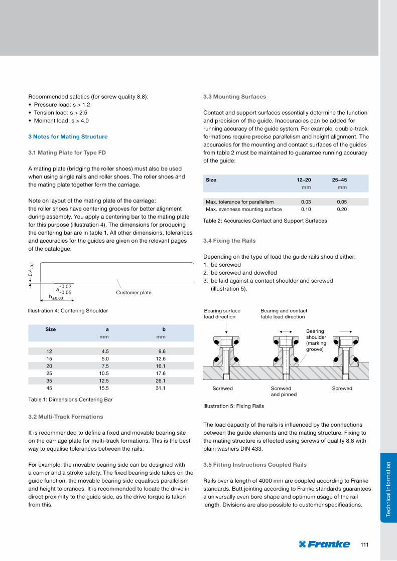
3.4 Fixing the Rails
Depending on the type of load the guide rails should either:1. be screwed2. be screwed and dowelled3. be laid against a contact shoulder and screwed (illustration5).
The load capacity of the rails is influenced by the connections betweentheguideelementsandthematingstructure.Fixingtothe mating structure is effected using screws of quality 8.8 with plainwashersDIN433.
3.5 Fitting Instructions Coupled Rails
Railsoveralengthof4000mmarecoupledaccordingtoFrankestandards.ButtjointingaccordingtoFrankestandardsguaranteesauniversallyevenboreshapeandoptimumusageoftheraillength.Divisionsarealsopossibletocustomerspecifications.
Illustration5:FixingRails

112
Size Auxiliary Cylinder mm
12 11
15 11
20 14
25 16
35 27
45 35
Table3:DimensionsAuxiliaryCylinder
Illustration6:CoupledRails/AuxiliaryCylinders
Technical Information
Therelevanttighteningtorquesfortheindividualscrewsaregivenintable4.
Screws Tightening Torque
M 3 1.1
M 4 2.5
M 5 5.0
M 6 8.5
M 8 21.0
M10 41.0
M12 71.0
Table4:TighteningTorquesScrews
3.6 Slide Resistances
Size Slide Resistance N FDA FDB FDC FDD FDE FDG FDH
12 Min. 0.2 0.2 0.5 – 0.5 0.6 –
Max. 0.4 0.4 1.0 – 3.0 0.9 –
15 Min. 0.5 0.5 0.5 – 1.0 0.5 –
Max. 2.0 1.0 2.0 – 3.0 1.5 –
20 Min. 1.0 0.5 1.0 – 1.0 1.0 –
Max. 2.5 1.5 2.5 – 3.0 3.0 –
25 Min. 1.5 0.5 1.5 1.5 1.5 0.5 2.5
Max. 3.0 2.0 3.0 3.0 3.0 2.0 5.0
35 Min. 2.0 1.0 2.0 – 2.0 1.0 4.0
Max. 4.0 2.5 4.0 – 4.0 2.5 7.0
45 Min. 2.5 2.0 2.5 – 2.5 2.0 5.0
Max. 5.0 4.0 5.0 – 5.0 4.0 8.0
Therailsarealsomarkedwithagrooveontherailunderside,which must always be on the same side. The rails must be arrangedfreeofplay.Thecorrespondingauxiliarycylinders(illustration6)areusedforthis.Thedimensionsforthedesign oftheauxiliarycylindersareintable3.Thecylindersareinserted at the joints of the rails in the raceway and preloaded usingadevice.
Coupled rails are specially aligned with one another. Therefore, therailshavesequentialnumberingfortherightfitting(e.g.A/1-1/1-2/2-2/E).
TechnicalInformation
µm
100
90
80
70
60
50
40
30
20
10
0 12 15 20 25 35 45 Size
Franke Dynamic running accuracy over 1 m
FDB,FDGFDA, FDC, FDD, FDE
FDH
3.7 Running Accuracy and Stiffness
Degree
1.0
0.9
0.8
0.7
0.6
0.5
0.4
0.3
0.2
0.1
0 100 200 300 400 500 600 700 800 Nm
Stiffness on the X-axis: FDA, FDC, FDD, FDE, FDH
12
1520
45
2535
Degree
0.150
0.135
0.120
0.105
0.090
0.075
0.060
0.045
0.030
0.015
0 10 20 30 40 50 60 70 80 Nm
Stiffness on the X-axis: FDB, FDG
25
35
20
45
12
15

113
FrankeRecirculatingRollerGuidesareavailableinonepreloadclass.Traversespeedsof3m/sandaccelerationsof30m/s²are possible. The operating temperature of the guides lies between–20°Cand+80°C. 2 Dimensioning the Guides
The following parameters are needed for correct dimensioning of the guide:•Selectionofformation•Allinvasiveoremergingforces/torques(dynamic/static),(seeillustration1)
•Typeofload(stationary,swelling,changing)•Environmentalinfluences(e.g.temperature,moisture)orspecialoperatingconditions(e.g.cleanroom,vacuum)
•Traversespeedandacceleration•Strokelength•Targetlifetimeinkm
All forces and torques must be within the permissible limits. Therelevantdataareonthepagesfortheindividualtypes.
Recommendedsafeties(forscrewquality8.8):•Pressureload:s>1.2•Tensionload:s>2.5•Momentload:s>4.0
Calculations can be performed by Franke.
3 Notes for Mating Structure
3.1 Multi-Track Formations
Itisrecommendedtodefineafixedandmovablebearingsite onthecarriageplateformulti-trackformations.Thisisthebestway to equalise tolerances between the rails.
Type FP – Franke Power
1 Designs and System Description
FrankeLinearGuidesofthetypeFPAcomprisedoublerails with cassette. The cassette has integrated recirculating rollers for high load ratings and stiffness. The rails of the type FPA are interchangeablewiththerailsoftheFrankeAluminiumRollerGuide.
TechnicalInformation
Forexample,themovablebearingsidecanbedesignedwith acarrierandastrokesafety.Thefixedbearingsidetakesontheguidefunction,themovablebearingsideequalisesparallelismandheighttolerances.Itisrecommendedtolocatethedriveindirectproximitytotheguideside,asthedrivetorqueistakenfrom this.
3.2 Mounting Surfaces
Contact and support surfaces essentially determine the function andprecisionoftheguide.Inaccuraciescanbeaddedfor runningaccuracyoftheguidesystem.Forexample,double-track formations require precise parallelism and height alignment. The accuracies for the mounting and contact surfaces of the guides from table 1 must be maintained to guarantee running accuracy of the guide:
Size 25 mm
Max.toleranceforparallelism 0.05
Max.evennessmountingsurface 0.20
Table1:AccuraciesBearingandContactSurfaces
All other dimensions, tolerances and accuracies for the guides aregivenontherelevantpagesofthecatalogue.
3.3 Fixing the Rails
Depending on the type of load the guide rails should either:1. be screwed2. be screwed and dowelled3. be laid against a contact shoulder and screwed (illustration2).
Illustration2:FixingRails
Illustration1:Arrangementofforcesandmoments

114
Technical Information
The load capacity of the rails is influenced by the connections betweentheguideelementsandthematingstructure.Fixingtothe mating structure is effected using screws of quality 8.8 with plainwashersDIN433.
3.4 Fitting Instructions Coupled Rails
Railsoveralengthof4000mmarecoupledaccordingtoFrankestandards.ButtjointingaccordingtoFrankestandardsguarantees auniversallyevenboreshapeandoptimumusageoftheraillength.Divisionsarealsopossibletocustomerspecifications.
Coupled rails are specially aligned with one another. Therefore, therailshavesequentialproductionnumberingfortherightfitting(e.g.A/1-1/1-2/2-2/E).
Therailsarealsomarkedwithagrooveontherailunderside,which must always be on the same side. The rails must be arrangedfreeofplay.Thecorrespondingauxiliarycylinders(illustration3)areusedforthis.Thedimensionsforthedesign oftheauxiliarycylindersareintable2.Thecylindersare inserted at the joints of the rails in the raceway and preloaded usingadevice.
TechnicalInformation
Therelevanttighteningtorquesfortheindividualscrewsaregivenintable3.
Size Auxiliary Cylinder mm
25 16
Table2:DimensionsAuxiliaryCylinder
Screws Tightening Torque
M6 8.5
M8 21.0
Table3:TighteningTorquesScrews
4 Lubrication
TheRecirculatingRollerGuidesareinitiallylubricatedexworks.Afterapprox.2000kmofrunningperformance,theguidesmustbe relubricated with 1 to 2 grams of lubricant.
5 Slide Resistances
Illustration3:CoupledRails/AuxiliaryCylinders
Size Slide resistance N FP
25 Min. 17.5
Max. 30.0
6 Running Accuracy and Stiffness
µm
50
45
40
35
30
25
20
15
10
5
0 12 15 20 25 35 45 Size
Franke Power running accuracy over 1 m
FP
Degree
1.0
0.9
0.8
0.7
0.6
0.5
0.4
0.3
0.2
0.1
0 40 80 120 160 200 240 280 Nm
Stiffness Franke Power
Size25bytheX-axis
Size25bytheY/Z-axis

115
TechnicalInformation
Illustration2:FixingRails
Type FR – Franke Robust
1 Designs and System Description
AluminiumRecirculatingBallGuidesoftypeFRAcomprisetwoindividualrailsandrecirculatingelements.Therecirculatingelements are mounted on the mating plate and together form the carriage. The construction of the mating plate is specified by the customer.
GuidesofthetypeFRAareparticularlyrobustandhavehighloadcapacity.Themax.traversespeedis3m/s,the max.accelerationis30m/s².Useispossibleinatemperaturerangeof–10°Cto+80°C.
TheslideresistancecanbeadjustedforLinearGuidesofthetypeFRA.Thefixingscrewsonthesliderplateontheadjustmentsidemustbeloosened.Usinganoptionaltooltherecirculatingelementcanbemovedtowardsthecarriageplateand the adjustment is altered. The adjustment setting is best determined by measuring the slide resistance in the unloaded state.
Theadjustmentvaluesareshownintable5SlideResistances.Furtherdetailsonfittingandadjustingtheguidearegivenin theinstructionmanualfortheAluminiumRecirculatingBallGuides.
2 Dimensioning the Guides
The following parameters are needed for correct dimensioning of the guide:•Selectionofformation•Allinvasiveoremergingforces/torques(dynamic/static),(seeillustration1)
•Typeofload(stationary,swelling,changing)•Environmentalinfluences(e.g.temperature,moisture)orspecialoperatingconditions(e.g.cleanroom,vacuum)
•Traversespeedandacceleration•Strokelength•Targetlifetimeinkm
All forces and torques must be within the permissible limits. Therelevantdataareonthepagesfortheindividualtypes.
Recommendedsafeties(forscrewquality8.8):•Pressureload:s>1.2•Tensionload:s>2.5•Momentload:s>4.0
Calculations can be performed by Franke.
3 Notes for Mating Structure
3.1 Mounting Surfaces Contact and support surfaces essentially determine the function andprecisionoftheguide.Inaccuraciescanbeaddedfor running accuracy of the guide system. Therefore, the linearity and parallelism of the mating structure must be considered. Themaximumpermissibledeviationacrossthewholestrokeis0.04 mm.
3.2 Fixing the Rails Therailsarefixedagainstabearingshoulderandscrewed(seeillustration 2). The two guide rails must be fitted parallel to one another. This is how you control the linearity and parallelism of therails.Themaximumtotalerrormustbelessthan0.06mm.
The load capacity of the rails is influenced by the connections betweentheguideelementsandthematingstructure.Fixingtothe mating structure is effected using screws of quality 8.8 with plainwashersDIN433.
Illustration1:Arrangementofforcesandmoments

116
Technical Information
TechnicalInformation
Note:theracewaysofthetypeFRA08-13canbeexchangedintheeventofwear.Arail’sracewaysmustalwaysbecompletelyexchanged.Thenewracewaysareorderedaccordingtotheoriginal order or the item number of the rail.
3.3 Fitting Instructions Coupled Rails Railsoveralengthof4000mmarecoupledaccordingtoFrankestandards.ButtjointingaccordingtoFrankestandardsguarantees auniversallyevenboreshapeandoptimumusageoftheraillength.Divisionsarealsopossibletocustomerspecifications.
Coupled rails are specially aligned with one another. Therefore, therailshavesequentialproductionnumberingfortherightfitting(e.g.A/1-1/1-2/2-2/E).Thetopsideoftherailsis consistentlymarkedwithabevel.
Therailsmustbeevenlyalignedduringfitting.Theremustbe a fitting gap between the rails. The rails should be fitted at a temperatureofapprox.20°C.Thescrewtighteningtorques from table 1 apply in this instance:
5 Slide Resistances
Screw Tightening Torque
M 5 6.0
M 6 10.0
M 8 25.0
M10 49.0
Table1:TighteningTorquesScrewsFRA
Size Slide Resistance per Pair of Recirculating Elements N FR
6 35 – 45
8 60 – 80
10 90 – 120
13 150 – 200
6 Running Accuracy
µm
100
90
80
70
60
50
40
30
20
10
0 6 8 10 13 Size
Franke Robust running accuracy over 1 m
FR
There are more detailed instructions on fitting the rails in the instructionmanualforFrankeLinearGuideswithRecirculatingBalls.
4 Lubrication
TheAluminiumRecirculatingBallGuidesmustalwaysbecoatedwithafilmoflubricant.Thesystemneedstobelubricatedevery500 to 700 operating hours or 1 to 2 times a year.
Recirculatingelementsareconnectedtocentrallubricationasstandard.Thisprovidesrelubricationviatheboringonthemounting surface.

117
TechnicalInformation
Linear Tables/Modules
1 Design
FrankeLinearSystemsaresuitableforexampleforautomationtasks in measuring and testing processes or for rationalisation in the handling and fitting sector. The selection ranges from strokesfrom100mmto7000mm,driveiseffectedviaaspindleorbeltdrive.Thelightaluminiumconstructioncombinedwith the integrated Franke guide system allows high load ratings and torqueloads.Precisetechnicaldetailsareontherelevantpagesin the catalogue.
2 Area of Use
WerecommenduseofFrankeLinearSystemswithsafetys≥ 3 for simple loads or acceleration and moment loads. A safety of s ≥ 6 should be used for dynamic torques. You can choose any installationposition.Werecommendabedstoporabrakeforverticaloperation.
ThepositionaccuracyofthetypeFTBLinearSystemsis±0.025/300mm(IT7)inaccordancewiththespindlestiffnessaccuracy. Other accuracies are possible on request. The repeat accuracy is ≤0.01mm.TherunaccuracyoftheFTBLinearTablesis0.02/300mm.FrankeLinearTablescanbe usedinatemperaturerangeof–20°Cto+80°C.TheFTD15–35LinearSystemsaresuitableforpermanentoperation attemperaturesof–30°Cto+80°C.Pleasecontactus concerning use in other temperature ranges.
3 End Switches and Reference Switches
• Referenceswitches:FrankeLinearSystemsoftypeFTBhaveinductiveproximityswitches,whicharesettothefinalstrokeposition.Afurtherproximityswitchcanbeprovidedasareferenceswitchifdesired.WiththetypeFTCandFTDLinearModulesthereisthepossibilityofattachingafreelyadjust-ableendswitchtotheoutside.FrankeLinearSystems areequippedwithinductiveendandreferenceswitchesPNP-nc10-30VDCasstandard.PNP-no,NPN-noandNPN-ncswitchesareavailableonrequest.Theaddition or integration of a length measuring system with sinus or squarewavesignalispossibleonrequest.Shaftencoderscan be mounted on the motor.
•Multiaxisunits:FrankeLinearSystemscanbecombined toformmulti-axleunits.Thenecessaryanglesandadaptorplatesareselectedaccordingtoyourneeds.Wesupplycompletely fitted units, ready cabled and aligned, with other accessories on request.
•Motorisation:AnarrayofsteporservomotorscanbeconnectedtotheLinearSystems.Connectionflangesandcouplings are modified accordingly. The customer’s own motors can also be considered.
•MotorRedirection,Gears:themotorismountedintheextensionofthestrokeaxleasstandard.Forspecial applications, e.g. in limited space, a motor redirection can be integratedonrequestusingatoothedbeltorreversinggears.
Please call us.
4 Maintenance and Lubrication
FrankeLinearSystemsarelow-maintenanceandhavelifetimelubricationexworks.Norelubricationisrequireduptotheballscrew.Intheeventofgreaseescapingthroughthespindle,relubrication–dependingontheindividualcase–isrequired.Werecommendrelubricationatintervalsofapprox.700workinghourswithapprox.1–2ggrease.Ifnecessarycleantheinnerareas and the guide tracks and coat these with grease.
Fullysyntheticlubricantsarepreferredforlong-termlubrication.FrankeusesthefullysyntheticspeciallubricantISOFLEXTOPASNCA52atthefactory(manuf.Klüber).Werecommendhigh-qualitylithium-saponificategreasebasedonmineraloil.Whenmixinglubricants,thecompatibilityofthevariantsmustbe considered with regard to type of base oil, thickening agent, baseoilviscosityandNLGIclass.Forextremeconditions orextraordinaryoperatingconditions(vacuum,radiation, high temperature), you should speak to us or the lubricant manufacturer.
5 Definitions
• Therunningaccuracyisthegreatestpossibledeviationof anyoneplaceonthemovedtablesurfacefromtheidealstraightlineswhentheentirestroketrackpasses(subject totheunevennessofthesubconstruction).
•Thepositionaccuracyisthegreatestpossibledeviationfromtheachievementofapreselectedpoint,whichispassedfroma predefined point of origin.
•Therepeataccuracyisthegreatestpossibledeviation fromthemultipleachievementofapreselectedpoint.Themeasuringsystemusediscrucialforthelevelofaccuracy.
•Theresolutionisthesmallestpossibletraversepath.Itdepends on the spindle pitch, the ratio, the step angle and the classification of the measuring system. Errors in the positioning or repeat can be neutralised using the resolution. Therefore,itshouldalwaysbegreaterthanthedeviationfromthe permissible position accuracy.
Please follow assembly and maintenance instructions. They are included with every delivery.

118
w
d
h
Technical Information
TechnicalInformation
Type FTH
1 Design
FrankeLinearMotorModulesFTHDrivearesuitableforexamplefortasksinmeasuringandtestingprocessesaswellasinthehandlingandfittingsector.Strokesfrom200mm to5,300mmareavailable.Driveiseffectedviaanintegratedlinear motor. The light aluminum construction oft he integrated Franke guide system allows high load ratings and torque loads.
2 Area of Use
WerecommendusewithsafetyS≥ 3 for simple loads or accelerationandmomentloads.AsafetyofS≥ 6 should be used for dynamic torques. You can choose any installation position.Werecommendabedstoporabrakeforvertical operation.
FrankeLinearMotorModulesFTHDrivecanbeusedinatemperaturerangeof–20°Cto+80°C.Pleasespeaktousabout use in other temperature ranges.
3 Accuracy
The positioning accuracy is ±0.01 mm/m and depends on the measuring system used. Other accuracies and measuring systems are possible. The repeat accuracy is ≤ 0.02mm. The running accuracy is 0.04 mm/m.
4 Dynamic
Theperformancegiveninthediagrams(page119)canberealizedwithFrankeLinearMotorModulesFTHDrive.These areguidevaluesthatrelatetothehorizontalfeedmotionin thetrapezeandtrianglepositioning.Wearehappytodesign the perfect linear motor for your application.
5 Motorization
TheLinearMotorModulesFTHDrivearepoweredbylinearservomotorswithoutmechanicaldrivecomponents.Thelinearmotor consists of a slide element and guide element. The slide element houses the coils, the position acquisition and temperaturemonitoring.Thedrivemagnetsarelocatedintheguide element.
Thelinearmotorsusedarecharacterizedbyextremelyhighpowerdensity(highestdynamicwithsmallestsize),thus,facilitating acceleration up to 100 m/s2andmovementspeedsup to 9 m/s.
6 Control
WerecommendtheS700amplifierfromKollmorgentopowertheLinearMotorModulesFTHDrive.TheS700offersmanyspecialfeatures,e.g.thefreegraphicWindows® software to operatetheamplifier.TheAuto-Tuningfunctionalsosimplifiesoperation.ASafeTorqueOffisincludedasstandard.TheS700canmemorizemanydifferentreturnsystemsandcanevaluateup to three lots of position information in parallel.
Youcangetmoreinformationfromourserviceteamorinthe internet at www.kollmorgen.com.
7 Measuring System and End and Reference Switches
FrankeLinearMotorModulesareequippedwithanintegrated,magnetic length measuring system as standard. The positioning accuracyis±10µmwitharesolutionof±1µm.Absolutemeasuring systems can also be fitted.
Inductiveproximityswitchesareavailabletorecordendorreference positions, which can be freely positioned in the guide profile.
8 Multi-Module Units
LinearMotorModulesoftypeFTHDrivecanbecombinedintomulti-moduleunits.Thenecessaryanglesandadaptorplatesareselectedaccordingtoyourneeds.Wesupplycompletelyfitted units, ready cabled and aligned, with other accessories on request.
Please follow assembly and maintenance instructions.They are included with every delivery.
Dimensions mmh(incl.ventilator) w d(incl.connector)
345 70 243

119
TechnicalInformation
mm
3000
2500
2000
1500
1000
500
0 300 400 500 600 700 800 900 1000 ms
1 kg
10 kg40 kg
20 kg
30 kg
triangular operation TypeFTH35B
mm
3000
2500
2000
1500
1000
500
0 300 400 500 600 700 800 900 1000 ms
1 kg5 kg
20 kg
10 kg
15 kg
triangular operation TypeFTH35A
m/s
7
6
5
4
3
2
1
0 0.68 0.926 1.19 1.471 1.667 m
1 kg 5 kg 20 kg10 kg 15 kg
acceleration to Vmax 6 m/s TypeFTH35A
38 m/s2 27 m/s2 15 m/s221 m/s2 17 m/s2
m/s
7
6
5
4
3
2
1
0 0.625 0.833 1.111 1.389 1.613 m
1 kg 10 kg 40 kg20 kg 30 kg
acceleration to Vmax 6 m/s TypeFTH35B
40 m/s2 30 m/s2 15.5 m/s222.5 m/s2 18 m/s2
m/s
10
9
8
7
6
5
4
3
2
1
0 1.185 2.192 3.42 4.68 m
1 kg 5 kg 10 kg 15 kg
acceleration to Vmax 9 m/sTypeFTH25A
34 m/s2 18.5 m/s2 11.8 m/s2 8.7 m/s2
mm
3000
2500
2000
1500
1000
500
0 300 400 500 600 700 800 900 1000 ms
1 kg
5 kg
10 kg15 kg
triangular operation TypeFTH25A
mm
3000
2500
2000
1500
1000
500
0 300 400 500 600 700 800 900 1000 ms
triangular operation TypeFTH25B
1 kg
5 kg
10 kg
15 kg
acceleration to Vmax 4.5 m/sTypeFTH25Bm/s
5
4.5
4
3.5
3
2.5
2
1.5
1
0.5
0 0.232 0.673 0.985 1.293 m
1 kg 5 kg 10 kg 15 kg
43.7 m/s2 15.1 m/s2 10.3 m/s2 7.8 m/s2