Embed Size (px)
Citation preview
DRAFT
Copyright (c) 2005 SISO Inc. All rights reserved. This is an unapproved SISO draft document, subject to change.
LINK 16 SIMULATION STANDARD SISO-STD-002-V2.9.6 DRAFT 29 March 2005 Tactical Digital Information Link-Technical Advice and Lexicon for Enabling Simulation (TADIL-TALES) Adin Burroughs, Northrop Grumman Information Technology Graham Shanks, AMS Robert Butterfield, ASTi Joe Sorroche, DMOC/ASRCC Neil Barrett, JITC Robert Byers, Northrop Grumman Information Technology James Nutaro, JITC, Northrop Grumman Information Technology Mary Christopher, AFRL/SNZW, CACI Technologies Bill Hinkle, Lockheed-Martin
DRAFT SISO-STD-002-V2.9.6
29 March 2005
ii Copyright (c) 2005 SISO Inc. All rights reserved.
This is an unapproved SISO draft document, subject to change.
TABLE OF CONTENTS Page
ACKNOWLEDGMENT .........................................................................................V
INTRODUCTION..................................................................................................VI
1. SCOPE............................................................................................................1
2. REFERENCES................................................................................................1
3. TERMS, DEFINITIONS AND CONVENTION..................................................2
3.1 CONVENTIONS......................................................................................2 3.2 TERMS AND DEFINITIONS ...................................................................2
4. ACRONYMS ...................................................................................................7
5. REQUIREMENTS ...........................................................................................8
5.1 JTIDS OPERATING CHARACTERISTICS .............................................8 5.1.1 General Requirements .................................................................8 5.1.2 Levels of Fidelity...........................................................................11 5.1.3 Communication between JUs with different fidelity levels ............13 5.1.4 Time Synchronization ...................................................................14
5.2 JTIDS IMPLEMENTATION UNDER DIS.................................................17 5.2.1 Transmitter PDU Description........................................................17 5.2.2 Signal PDU Description ................................................................20
5.3 IMPLEMENTATION OF LINK 16 UNDER THE HLA...............................30 5.3.1 The Link 16 BOM .........................................................................31 5.3.2 Levels of Fidelity...........................................................................31 5.3.3 Time Synchronization ...................................................................31 5.3.4 Protocol Implementation Details ...................................................31 5.3.5 BOM Implementation....................................................................33 5.3.6 Adding the Link 16 BOM to the RPR FOM ...................................33
ANNEX A: LINK 16 BASE OBJECT MODEL (BOM) OMT 1.3 TABLES........A-1
A.1 OBJECT MODEL IDENTIFICATION TABLE...........................................A-1 A.2 OBJECT INTERACTION TABLE ............................................................A-1
DRAFT SISO-STD-002-V2.9.6
29 March 2005
iii Copyright (c) 2005 SISO Inc. All rights reserved.
This is an unapproved SISO draft document, subject to change.
TABLE OF CONTENTS Page
A.3 PARAMETER TABLE .............................................................................A-2 A.4 ENUMERATED DATATYPES TABLE ....................................................A-3 A.5 COMPLEX DATATYPES TABLE............................................................A-3 A.6 NOTES TABLE .......................................................................................A-4
ANNEX B: EXAMPLE LINK 16 TRANSMITTER/SIGNAL PDUS ...................B-1
B.1 TSA LEVEL 0 TRANSMITTER PDU .......................................................B-1 B.2 TSA LEVEL 0 SIGNAL PDU ...................................................................B-2 B.3 TSA LEVEL 1 TRANSMITTER PDU .......................................................B-3 B.4 TSA LEVEL 1 SIGNAL PDU ...................................................................B-4 B.5 TSA LEVEL 2 TRANSMITTER PDU .......................................................B-5 B.6 TSA LEVEL 2 SIGNAL PDU ...................................................................B-6 B.7 TSA LEVEL 3 TRANSMITTER PDU .......................................................B-7 B.8 TSA LEVEL 3 SIGNAL PDU ...................................................................B-8
LIST OF TABLES Page
Table 5.1.1. JTIDS Communication Modes .........................................................10
Table 5.1.2: JTIDS Levels of Fidelity ....................................................................11
Table 5-1-2: JTIDS Levels of Fidelity (Continued) ................................................12
Table 5.2.1: Transmitter PDU for TADIL J ..........................................................18
Table 5.2.1: Transmitter PDU for TADIL J (Continued) .......................................19
Table 5.2.2: Message Type Identifiers..................................................................21
Table 5.2.2: Message Type Identifiers (Continued) ..............................................22
Table 5.2.3: TADIL J Message Bit Orientation......................................................23

DRAFT SISO-STD-002-V2.9.6
29 March 2005
iv Copyright (c) 2005 SISO Inc. All rights reserved.
This is an unapproved SISO draft document, subject to change.
LIST OF TABLES (CONTINUED) Page
Table 5.2.4: SIGNAL PDU for TADIL J.................................................................24
Table 5.2.4: SIGNAL PDU for TADIL J (Continued) .............................................25
Table 5.2.5: Message Type = 0, JTIDS Header/Message....................................26
Table 5.2.6 Message Type = 1, RTT A/B .............................................................26
Table 5.2.7: Message Type = 2, RTT Reply .........................................................27
Table 5.2.8: Message Type = 3, JTIDS Voice CVSD ...........................................27
Table 5.2.9: Message Type = 4, JTIDS Voice LPC10 ..........................................28
Table 5.2.10: Message Type = 5, JTIDS Voice LPC12 ........................................28
Table 5.2.11: Message Type = 6, JTIDS LET Header/Message ..........................29
Table 5.2.12: Message type = 7, VMF Header/Messages....................................30
Table 5.3.1: Link 16 BOM Interactions in the RPR-FOM ......................................33

DRAFT SISO-STD-002-V2.9.6
29 March 2005
v Copyright (c) 2005 SISO Inc. All rights reserved.
This is an unapproved SISO draft document, subject to change.
ACKNOWLEDGMENT This protocol is the result of the efforts of the SISO Link 16 Product Development Group. This group is the successor to the SISO Tactical Data Link Study Group, which began as a “grass roots” response to informal community inquiries by TACCSF. The Study Group presented a DIS implementation of Tactical Data Link at the Fall 2003 SIW. This protocol would not have been possible without the contributions and hard work of each of its members.
DRAFT SISO-STD-002-V2.9.6
29 March 2005
vi Copyright (c) 2005 SISO Inc. All rights reserved.
This is an unapproved SISO draft document, subject to change.
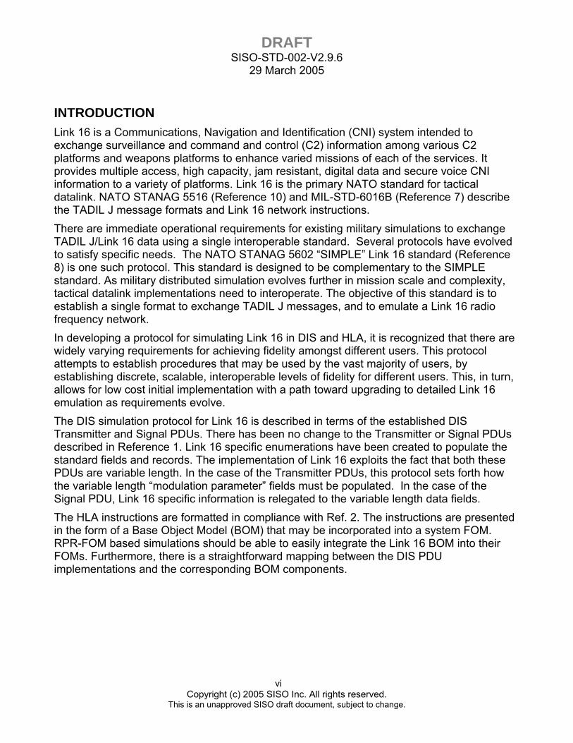
INTRODUCTION Link 16 is a Communications, Navigation and Identification (CNI) system intended to exchange surveillance and command and control (C2) information among various C2 platforms and weapons platforms to enhance varied missions of each of the services. It provides multiple access, high capacity, jam resistant, digital data and secure voice CNI information to a variety of platforms. Link 16 is the primary NATO standard for tactical datalink. NATO STANAG 5516 (Reference 10) and MIL-STD-6016B (Reference 7) describe the TADIL J message formats and Link 16 network instructions. There are immediate operational requirements for existing military simulations to exchange TADIL J/Link 16 data using a single interoperable standard. Several protocols have evolved to satisfy specific needs. The NATO STANAG 5602 “SIMPLE” Link 16 standard (Reference 8) is one such protocol. This standard is designed to be complementary to the SIMPLE standard. As military distributed simulation evolves further in mission scale and complexity, tactical datalink implementations need to interoperate. The objective of this standard is to establish a single format to exchange TADIL J messages, and to emulate a Link 16 radio frequency network. In developing a protocol for simulating Link 16 in DIS and HLA, it is recognized that there are widely varying requirements for achieving fidelity amongst different users. This protocol attempts to establish procedures that may be used by the vast majority of users, by establishing discrete, scalable, interoperable levels of fidelity for different users. This, in turn, allows for low cost initial implementation with a path toward upgrading to detailed Link 16 emulation as requirements evolve. The DIS simulation protocol for Link 16 is described in terms of the established DIS Transmitter and Signal PDUs. There has been no change to the Transmitter or Signal PDUs described in Reference 1. Link 16 specific enumerations have been created to populate the standard fields and records. The implementation of Link 16 exploits the fact that both these PDUs are variable length. In the case of the Transmitter PDUs, this protocol sets forth how the variable length “modulation parameter” fields must be populated. In the case of the Signal PDU, Link 16 specific information is relegated to the variable length data fields. The HLA instructions are formatted in compliance with Ref. 2. The instructions are presented in the form of a Base Object Model (BOM) that may be incorporated into a system FOM. RPR-FOM based simulations should be able to easily integrate the Link 16 BOM into their FOMs. Furthermore, there is a straightforward mapping between the DIS PDU implementations and the corresponding BOM components.
DRAFT SISO-STD-002-V2.9.6
29 March 2005
1 Copyright (c) 2005 SISO Inc. All rights reserved.
This is an unapproved SISO draft document, subject to change.
1. SCOPE It is the objective of this protocol to establish a standard for TADIL J message exchange and LINK 16 network simulation in the DIS and HLA interoperability frameworks. The intent is to prescribe the content of the standard fields of the Transmitter and Signal PDUs and establish procedures for their use. Compliance with these procedures will facilitate interoperability among LINK 16 simulation systems.
2. REFERENCES 1. IEEE 1278.1a–1998 IEEE Standard for Distributed Interactive Simulation – Application
Protocols 2. IEEE 1516 –2000 IEEE Standard for Modeling and Simulation (M&S) High Level
Architecture (HLA) 3. High Level Architecture Object Model Template Specification v1.3, 5 February 1998 4. IST-CF-03-01—5 May 2003: Enumeration and Bit Encoded Values for Use with
Protocols for Distributed Interactive Simulation Applications 5. SISO-STD-001--1999: Real-time Platform Reference Federation Object Model,
Version 1.0, 14 September, 1999 6. RPR-FOM 2.0 Draft 17, Real-time Platform Reference Federation Object Model,
Version 2.0, Draft 17, 10 September 2003. 7. MIL-STD-6016B, Tactical Digital Information Link (TADIL) J Message Standard
(DRAFT) 15 March 2002 8. NATO STANAG 5602, edition 1, Standard Interface for Multiple Platform Link
Evaluation (SIMPLE) 20 Feb 2001 9. System Segment Specification for Joint Tactical Information Distribution System Class
2 Terminal, 15 April 1999 10. NATO STANAG 5516, Edition 1, Tactical Data Exchange - LINK 16, Ratified 15
January 1997. 11. LINK 16 Enhanced Throughput Standard, August 11, 1998 Doc # VSD-618255-97-
339-02 12. Joint Interoperability of Tactical Command and Control Systems Variable Message
Format (VMF) Technical Interface Design Plan (Test Edition) Reissue 2, August 1996. 13. RFC 1305, Network Time Protocol (v3) Specifications, Implementation & Analysis,
March 1992 14. Time Synchronization Server, http://www.ntp.org
DRAFT SISO-STD-002-V2.9.6
29 March 2005
2 Copyright (c) 2005 SISO Inc. All rights reserved.
This is an unapproved SISO draft document, subject to change.
3. TERMS, DEFINITIONS AND CONVENTION
3.1 CONVENTIONS The following terms and conventions are used for the purpose of this standard:
• SHALL indicates a procedure or capability is mandatory.
• SHOULD indicates a recommended procedure or capability.
• MAY indicates a procedure or capability is optional.
• WILL/IS/ARE are generally used descriptively for information purposes.
3.2 TERMS AND DEFINITIONS Automatic Acknowledgement: A machine verification function whereby a terminal that receives a message addressed to it retransmits a copy of that message back to the source during a later time slot, verifying the receipt of the original message. Epoch: A 12.8-minute time interval consisting of 98,304 time slot intervals, each of 7.8125 milliseconds duration. The time slots in each epoch are organized into three sets (A, B, or C) of 32,768 time slots each. There are 112.5 epochs in a 24-hour period. Free Text Message: Bit-oriented messages whose information bits may be used to represent digitized voice, teletype and other forms of free text information. This does not refer to the fixed word format message, J28.2 “AWACS free text message.” Fidelity Level: In terms of this standard, a fidelity level is a measure of the level of functionality of the implementation of the Link 16 Simulation Standard. This allows for a standard nomenclature to be used within the community to describe the functionality of implementations of this standard. See section 5.1.2 for additional information and table 5.1.2 for definitions of fidelity levels in this standard. Fixed Word Format (FWF): A 70-bit structure consisting of a formalized arrangement of predefined fields of fixed length and sequence. Fixed Word Format Message: A J Series message utilizing Fixed Word Format (FWF). An FWF message is started by an initial word that may be then followed by one or more extension and/or continuation words.
Geodetic Position Quality: A measure of the quality of a JTIDS/MIDS terminal's geodetic position reported in the terminal's Position and Status Reports. Geodetic Position Quality is reported as an integer from 0-15 where the higher numbers correspond to the higher qualities, i.e., lower errors in position. Initial Entry: The procedure by which a subscriber terminal becomes a system participant initially and may achieve coarse synchronization with system time. Initial Entry JTIDS Unit (IEJU): Any JTIDS/MIDS unit that transmits the Initial Entry message in the appropriate time slot.
DRAFT SISO-STD-002-V2.9.6
29 March 2005
3 Copyright (c) 2005 SISO Inc. All rights reserved.
This is an unapproved SISO draft document, subject to change.
Joint Tactical Information Distribution System (JTIDS): The JTIDS/MIDS is a joint-service system which provides an Integrated Communications, Navigation, and Identification (ICNI) capability. The JTIDS/MIDS provides a reliable, secure, jam resistant, high-capacity, ICNI capability through the use of direct-sequence, spread- spectrum, frequency-hopping, and error detection and correction techniques. JTIDS Header (Message): The leading bits of each message are coded as a Reed-Solomon code word that provides 35 bits of information. JTIDS/MIDS Net: One of 128 time-division structures comprising a JTIDS/MIDS network. Each net consists of a continuous stream of time intervals (time slots) with 98,304 time slots per 12.8-minute epoch, during which digital data whose signal characteristics are determined by a cryptographic variable in conjunction with a unique net number are distributed. JTIDS/MIDS Network: The JTIDS/MIDS structure (usable only with Mode 1 communications) having a total usable capacity of 98,304 time slots per epoch per net and 128 nets. All nets are synchronized so that each time slot of each net is time-coincident with the corresponding time slot (same set and number) of every other net. The signal characteristics of all data distributed within a specified multi-netted structure are determined by a cryptographic variable in conjunction with a set of net numbers that define the structure. JTIDS/MIDS Unit (JU): A unit communicating directly on Link 16. JU is used within the context of this standard to indicate a simulated TADIL J terminal. J-Word: JTIDS Word. Link 16 Message: See TADIL J. Machine Receipt: See Automatic Acknowledgement. Mode 1 Communications: Mode 1 JTIDS/MIDS transmissions consist of a sequence of wide-band transmission symbol packets (single pulse, 13-microsecond packets and double-pulse, 26-microsecond packets), the pulses of which are formed by continuous phase shift modulation (CPSM) of the carrier frequency. The signal processing required to transform base-band data to the JTIDS signal waveforms for transmission includes base-band data encryption, forward error correction encoding, error detection encoding, cyclic code shift keying (CCSK) encoding, data symbol interleaving, and the selection of a variable start time. Mode 2 Communications: Mode 2 JTIDS/MIDS transmissions are identical to Mode 1, except that Mode 2 operates in the narrow-band mode. Mode 4 Communications: Mode 4 JTIDS/MIDS transmissions have signal waveform characteristics identical to Mode 2, except that Mode 4 does not employ base-band data encryption signal processing. Navigation Controller: The Navigation Controller establishes the origin and North orientation of the U, V relative grid for the Relative Navigation function.
Needline/Network Participation Group (NPG): The Needline Participation Group is a unique list of netted subscribers compiled without regard to the specific messages they
DRAFT SISO-STD-002-V2.9.6
29 March 2005
4 Copyright (c) 2005 SISO Inc. All rights reserved.
This is an unapproved SISO draft document, subject to change.
exchange with each other. This list is a means of transmitting any message to a common set of users. The Network Participation Group is a unique list of applicable messages used to support an agreed upon technical function without regard to subscriber identities. This list is a means of transmitting a common set of messages to all interested users. For the purposes of simulation in this standard, the NPG number creates virtual networks of participants to segregate information within a JTIDS/MIDS network. Net: See "JTIDS/MIDS Net." Net Number: A 7-bit code that identifies each net as a decimal number (0 through 127). Network: See "JTIDS/MIDS Network." Network Time Reference (NTR): A subscriber terminal that is assigned as the reference for system time for each synchronized netted system. The NTR terminal's clock time is never updated by system information and is the reference to which all other terminals synchronize their own clocks. There is only one NTR. Position Reference: One or more JUs designated as a network reference. Such a JU has maintained a geodetic position accuracy of 50 feet, one sigma (standard deviation) over a long period of time. Pulse (JTIDS): A 6.4-microsecond burst of carrier frequency continuous phase shift modulated at a 5-megabit-per-second rate by the transmission symbol. Precise Participant Location & Identification (PPLI): The PPLI function provides network participation status, identification, and position of JUs on the Link 16 interface. Radio Silence Mode: A mode of terminal operation where the terminal receives but does not transmit fixed word format or variable message format messages. Recurrence Rate: The total number of time slots per epoch assigned (or deleted) in a single time block assignment, specified as an integer, R = 0 to 15 where 2R = the number of time slots. Recurrence Rate Number (RRN): An integer R, 0 ≤ R ≤ 15, where 2R
is the recurrence rate of the block assignment. Reed-Solomon (R-S) Code: As applied to JTIDS/MIDS, a forward error correction encoding scheme. In this protocol, indicating Reed-Solomon encoding in the Signal PDU, the data area is still comprised of 75 bit non Reed-Solomon encoded TADIL J messages. Relative Navigation (Relnav): A procedure used by a terminal to determine its position and velocity in a common reference coordinate system by passive observations of Position and Status messages transmitted by other terminals. To make use of Relnav, the simulation system must achieve medium fidelity synchronization (paragraph 5.4.2). Relative Position Quality: A measure of the quality of a terminal's relative position with respect to the U, V relative grid. Relative Position Quality is reported in the terminal's Position and Status Reports as an integer from 0-15, where higher numbers correspond to higher quality.
DRAFT SISO-STD-002-V2.9.6
29 March 2005
5 Copyright (c) 2005 SISO Inc. All rights reserved.
This is an unapproved SISO draft document, subject to change.
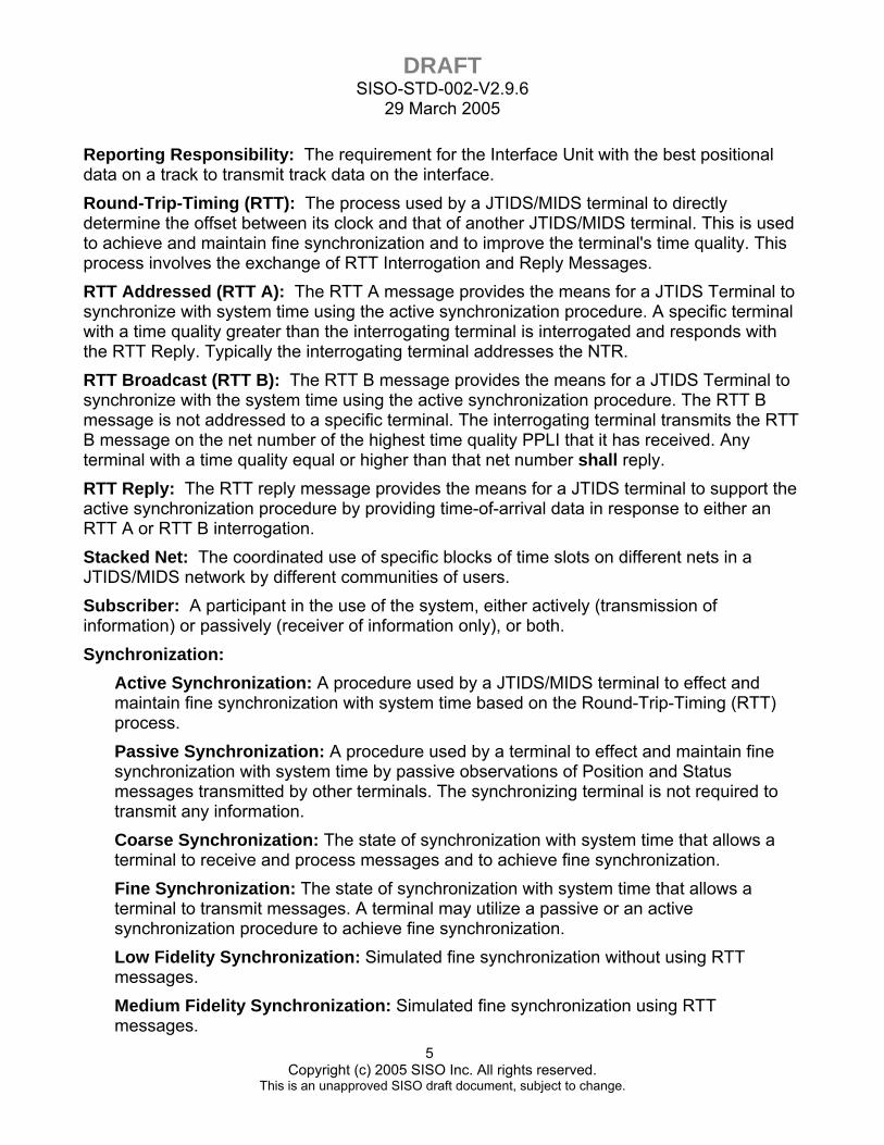
Reporting Responsibility: The requirement for the Interface Unit with the best positional data on a track to transmit track data on the interface. Round-Trip-Timing (RTT): The process used by a JTIDS/MIDS terminal to directly determine the offset between its clock and that of another JTIDS/MIDS terminal. This is used to achieve and maintain fine synchronization and to improve the terminal's time quality. This process involves the exchange of RTT Interrogation and Reply Messages. RTT Addressed (RTT A): The RTT A message provides the means for a JTIDS Terminal to synchronize with system time using the active synchronization procedure. A specific terminal with a time quality greater than the interrogating terminal is interrogated and responds with the RTT Reply. Typically the interrogating terminal addresses the NTR. RTT Broadcast (RTT B): The RTT B message provides the means for a JTIDS Terminal to synchronize with the system time using the active synchronization procedure. The RTT B message is not addressed to a specific terminal. The interrogating terminal transmits the RTT B message on the net number of the highest time quality PPLI that it has received. Any terminal with a time quality equal or higher than that net number shall reply. RTT Reply: The RTT reply message provides the means for a JTIDS terminal to support the active synchronization procedure by providing time-of-arrival data in response to either an RTT A or RTT B interrogation. Stacked Net: The coordinated use of specific blocks of time slots on different nets in a JTIDS/MIDS network by different communities of users. Subscriber: A participant in the use of the system, either actively (transmission of information) or passively (receiver of information only), or both. Synchronization:
Active Synchronization: A procedure used by a JTIDS/MIDS terminal to effect and maintain fine synchronization with system time based on the Round-Trip-Timing (RTT) process. Passive Synchronization: A procedure used by a terminal to effect and maintain fine synchronization with system time by passive observations of Position and Status messages transmitted by other terminals. The synchronizing terminal is not required to transmit any information. Coarse Synchronization: The state of synchronization with system time that allows a terminal to receive and process messages and to achieve fine synchronization. Fine Synchronization: The state of synchronization with system time that allows a terminal to transmit messages. A terminal may utilize a passive or an active synchronization procedure to achieve fine synchronization. Low Fidelity Synchronization: Simulated fine synchronization without using RTT messages. Medium Fidelity Synchronization: Simulated fine synchronization using RTT messages.
DRAFT SISO-STD-002-V2.9.6
29 March 2005
6 Copyright (c) 2005 SISO Inc. All rights reserved.
This is an unapproved SISO draft document, subject to change.
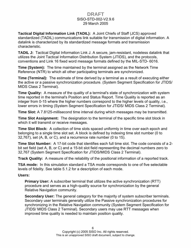
Tactical Digital Information Link (TADIL): A Joint Chiefs of Staff (JCS) approved standardized (TADIL) communications link suitable for transmission of digital information. A datalink is characterized by its standardized message formats and transmission characteristic. TADIL J: Tactical Digital Information Link J. A secure, jam-resistant, nodeless datalink that utilizes the Joint Tactical Information Distribution System (JTIDS), and the protocols, conventions and Link 16 fixed word message formats defined by the MIL-STD- 6016. Time (System): The time maintained by the terminal assigned as the Network Time Reference (NTR) to which all other participating terminals are synchronized. Time (Terminal): The estimate of time derived by a terminal as a result of executing either the active or a passive synchronization procedure. (System Segment Specification for JTIDS/ MIDS Class 2 Terminal). Time Quality: A measure of the quality of a terminal's state of synchronization with system time reported in the terminal's Position and Status Report. Time Quality is reported as an integer from 0-15 where the higher numbers correspond to the higher levels of quality, i.e., lower errors in timing (System Segment Specification for JTIDS/ MIDS Class 2 Terminal). Time Slot: A 7.8125-millisecond time interval during which messages may be transmitted. Time Slot Assignment: The designation to the terminal of the specific time slot block in which it will transmit or receive messages. Time Slot Block: A collection of time slots spaced uniformly in time over each epoch and belonging to a single time slot set. A block is defined by indexing time slot number (0 to 32,767), set (A, B, or C), and a recurrence rate number (0 to 15). Time Slot Number: A 17-bit code that identifies each full time slot. The code consists of a 2-bit set field (set A, B, or C) and a 15-bit slot field representing the decimal numbers zero to 32,767 (System Segment Specification for JTIDS/MIDS Class 2 Terminal). Track Quality: A measure of the reliability of the positional information of a reported track. TSA mode: In this simulation standard a TSA mode corresponds to one of five selectable levels of fidelity. See table 5.1.2 for a description of each mode. Users:
Primary User: A subscriber terminal that utilizes the active synchronization (RTT) procedure and serves as a high-quality source for synchronization by the general Relative Navigation community. Secondary User: The general category for the majority of system subscriber terminals. Secondary user terminals generally utilize the Passive synchronization procedures for synchronizing in the Relative Navigation community (System Segment Specification for JTIDS/ MIDS Class 2 Terminal). Secondary users may use RTT messages when improved time quality is needed to maintain position quality.

DRAFT SISO-STD-002-V2.9.6
29 March 2005
7 Copyright (c) 2005 SISO Inc. All rights reserved.
This is an unapproved SISO draft document, subject to change.
Variable Message Format (VMF): A message structure using predefined fields of fixed length employing internal syntax and a header extension. The internal syntax specifies the presence, absence, and recurrence of fields as selected by the user.
4. ACRONYMS BOM Base Object Model CNI Communication, Navigation, and Identification CPSM Continuous Phase Shift Modulation CVSD Continuous Variable Slope Delta (modulation) CVLL Crypto Variable Logic Label DIS Distributed Interactive Simulation DMOC Distributed Mission Operations Center EDAC Error Detection and Correction FOM Federation Object Model HLA High Level Architecture IEJU Initial Entry JTIDS unit JCS Joint Chiefs of Staff JTIDS Joint Tactical Information Distribution System JU JTIDS Unit LET Link 16 Enhanced Throughput LPC Linear Predictive Coding MIDS Multi-Function Information Distribution System MIL STD Military Standard MSEC Message Security Encryption Code NATO North Atlantic Treaty Organization NDL Network Data Load NPG Needline/Network Participation Group NTR Network Time Reference PDU Protocol Data Unit PPLI Precise Participant Location & Identification RelNav Relative Navigation R-S Encoding Reed-Solomon encoding
DRAFT SISO-STD-002-V2.9.6
29 March 2005
8 Copyright (c) 2005 SISO Inc. All rights reserved.
This is an unapproved SISO draft document, subject to change.
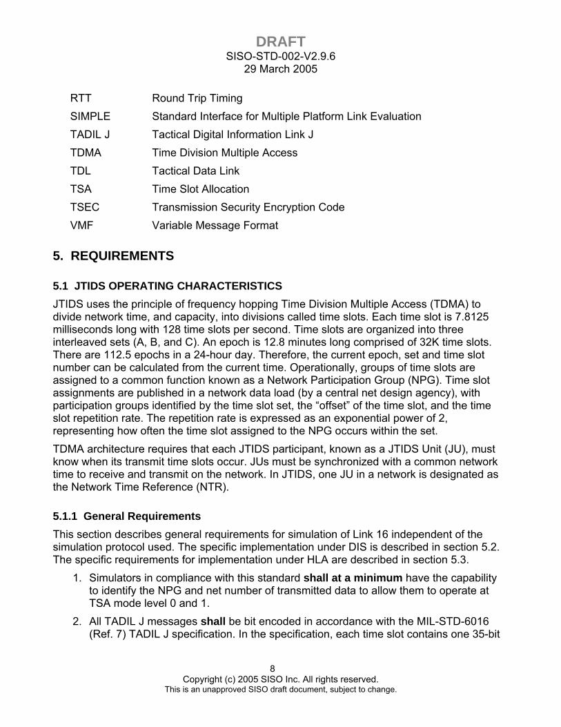
RTT Round Trip Timing SIMPLE Standard Interface for Multiple Platform Link Evaluation TADIL J Tactical Digital Information Link J TDMA Time Division Multiple Access TDL Tactical Data Link TSA Time Slot Allocation TSEC Transmission Security Encryption Code VMF Variable Message Format
5. REQUIREMENTS
5.1 JTIDS OPERATING CHARACTERISTICS JTIDS uses the principle of frequency hopping Time Division Multiple Access (TDMA) to divide network time, and capacity, into divisions called time slots. Each time slot is 7.8125 milliseconds long with 128 time slots per second. Time slots are organized into three interleaved sets (A, B, and C). An epoch is 12.8 minutes long comprised of 32K time slots. There are 112.5 epochs in a 24-hour day. Therefore, the current epoch, set and time slot number can be calculated from the current time. Operationally, groups of time slots are assigned to a common function known as a Network Participation Group (NPG). Time slot assignments are published in a network data load (by a central net design agency), with participation groups identified by the time slot set, the “offset” of the time slot, and the time slot repetition rate. The repetition rate is expressed as an exponential power of 2, representing how often the time slot assigned to the NPG occurs within the set. TDMA architecture requires that each JTIDS participant, known as a JTIDS Unit (JU), must know when its transmit time slots occur. JUs must be synchronized with a common network time to receive and transmit on the network. In JTIDS, one JU in a network is designated as the Network Time Reference (NTR).
5.1.1 General Requirements This section describes general requirements for simulation of Link 16 independent of the simulation protocol used. The specific implementation under DIS is described in section 5.2. The specific requirements for implementation under HLA are described in section 5.3.
1. Simulators in compliance with this standard shall at a minimum have the capability to identify the NPG and net number of transmitted data to allow them to operate at TSA mode level 0 and 1.
2. All TADIL J messages shall be bit encoded in accordance with the MIL-STD-6016 (Ref. 7) TADIL J specification. In the specification, each time slot contains one 35-bit
DRAFT SISO-STD-002-V2.9.6
29 March 2005
9 Copyright (c) 2005 SISO Inc. All rights reserved.
This is an unapproved SISO draft document, subject to change.
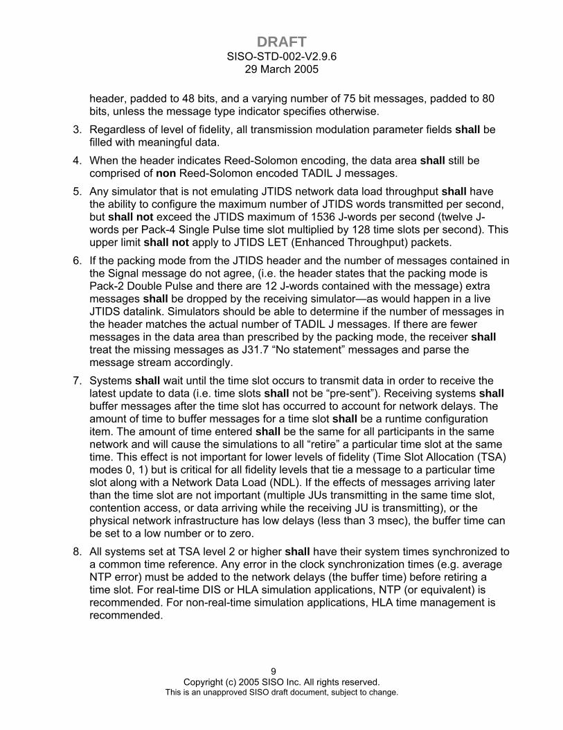
header, padded to 48 bits, and a varying number of 75 bit messages, padded to 80 bits, unless the message type indicator specifies otherwise.
3. Regardless of level of fidelity, all transmission modulation parameter fields shall be filled with meaningful data.
4. When the header indicates Reed-Solomon encoding, the data area shall still be comprised of non Reed-Solomon encoded TADIL J messages.
5. Any simulator that is not emulating JTIDS network data load throughput shall have the ability to configure the maximum number of JTIDS words transmitted per second, but shall not exceed the JTIDS maximum of 1536 J-words per second (twelve J-words per Pack-4 Single Pulse time slot multiplied by 128 time slots per second). This upper limit shall not apply to JTIDS LET (Enhanced Throughput) packets.
6. If the packing mode from the JTIDS header and the number of messages contained in the Signal message do not agree, (i.e. the header states that the packing mode is Pack-2 Double Pulse and there are 12 J-words contained with the message) extra messages shall be dropped by the receiving simulator—as would happen in a live JTIDS datalink. Simulators should be able to determine if the number of messages in the header matches the actual number of TADIL J messages. If there are fewer messages in the data area than prescribed by the packing mode, the receiver shall treat the missing messages as J31.7 “No statement” messages and parse the message stream accordingly.
7. Systems shall wait until the time slot occurs to transmit data in order to receive the latest update to data (i.e. time slots shall not be “pre-sent”). Receiving systems shall buffer messages after the time slot has occurred to account for network delays. The amount of time to buffer messages for a time slot shall be a runtime configuration item. The amount of time entered shall be the same for all participants in the same network and will cause the simulations to all “retire” a particular time slot at the same time. This effect is not important for lower levels of fidelity (Time Slot Allocation (TSA) modes 0, 1) but is critical for all fidelity levels that tie a message to a particular time slot along with a Network Data Load (NDL). If the effects of messages arriving later than the time slot are not important (multiple JUs transmitting in the same time slot, contention access, or data arriving while the receiving JU is transmitting), or the physical network infrastructure has low delays (less than 3 msec), the buffer time can be set to a low number or to zero.
8. All systems set at TSA level 2 or higher shall have their system times synchronized to a common time reference. Any error in the clock synchronization times (e.g. average NTP error) must be added to the network delays (the buffer time) before retiring a time slot. For real-time DIS or HLA simulation applications, NTP (or equivalent) is recommended. For non-real-time simulation applications, HLA time management is recommended.
DRAFT SISO-STD-002-V2.9.6
29 March 2005
10 Copyright (c) 2005 SISO Inc. All rights reserved.
This is an unapproved SISO draft document, subject to change.
9. All systems should have some representation of a terminal clock time. If medium fidelity synchronization is to be accomplished, the system shall model a terminal clock (and its associated drift).
10. At TSA level 2 or greater, if multiple messages are received with identical TSEC, net number and timeslot number, receivers shall not process messages except from the closest transmitting entity (in the simulation space).
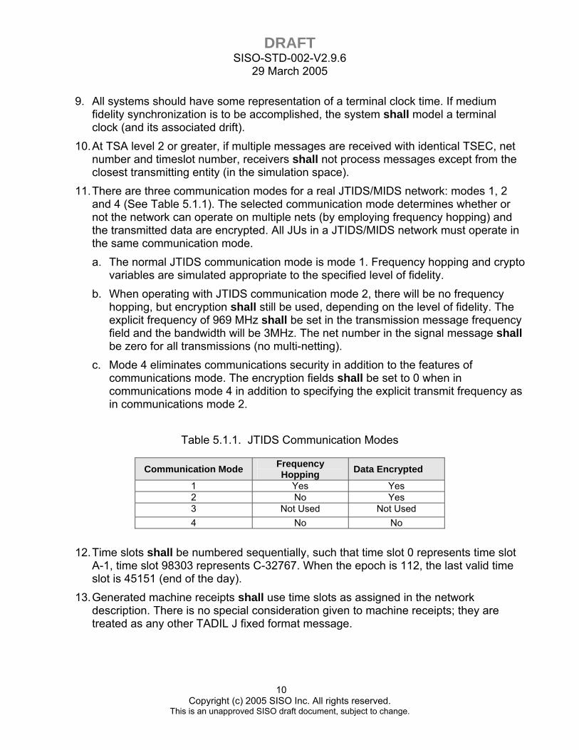
11. There are three communication modes for a real JTIDS/MIDS network: modes 1, 2 and 4 (See Table 5.1.1). The selected communication mode determines whether or not the network can operate on multiple nets (by employing frequency hopping) and the transmitted data are encrypted. All JUs in a JTIDS/MIDS network must operate in the same communication mode. a. The normal JTIDS communication mode is mode 1. Frequency hopping and crypto
variables are simulated appropriate to the specified level of fidelity. b. When operating with JTIDS communication mode 2, there will be no frequency
hopping, but encryption shall still be used, depending on the level of fidelity. The explicit frequency of 969 MHz shall be set in the transmission message frequency field and the bandwidth will be 3MHz. The net number in the signal message shall be zero for all transmissions (no multi-netting).
c. Mode 4 eliminates communications security in addition to the features of communications mode. The encryption fields shall be set to 0 when in communications mode 4 in addition to specifying the explicit transmit frequency as in communications mode 2.
Table 5.1.1. JTIDS Communication Modes
Communication Mode Frequency Hopping Data Encrypted
1 Yes Yes 2 No Yes 3 Not Used Not Used 4 No No
12. Time slots shall be numbered sequentially, such that time slot 0 represents time slot A-1, time slot 98303 represents C-32767. When the epoch is 112, the last valid time slot is 45151 (end of the day).
13. Generated machine receipts shall use time slots as assigned in the network description. There is no special consideration given to machine receipts; they are treated as any other TADIL J fixed format message.
DRAFT SISO-STD-002-V2.9.6
29 March 2005
11 Copyright (c) 2005 SISO Inc. All rights reserved.
This is an unapproved SISO draft document, subject to change.
14. Relay is accomplished by transmitting relay information in assigned time slots. There is no special mechanism necessary to simulate relay transmissions.
15. Transmission messages shall only be sent with signal messages in conjunction with the following events: entering the Link 16 network, exiting the Link 16 network, during synchronization state changes, with PPLI messages, and with initial net entry messages.
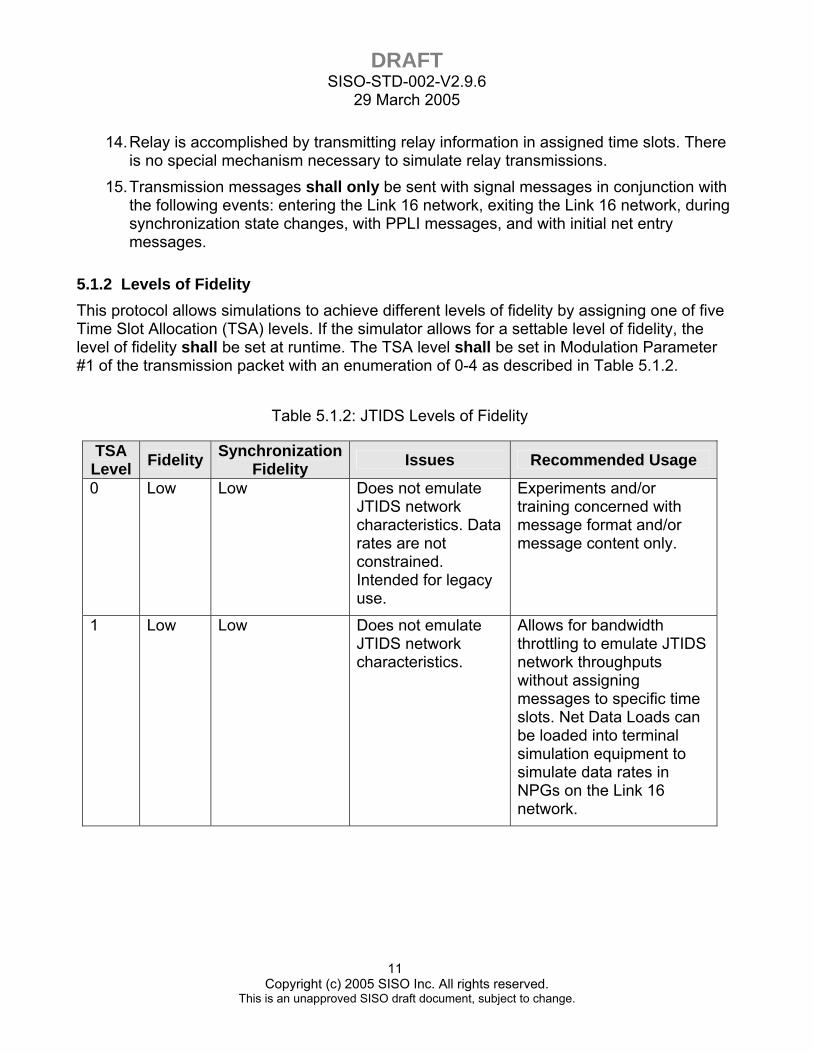
5.1.2 Levels of Fidelity This protocol allows simulations to achieve different levels of fidelity by assigning one of five Time Slot Allocation (TSA) levels. If the simulator allows for a settable level of fidelity, the level of fidelity shall be set at runtime. The TSA level shall be set in Modulation Parameter #1 of the transmission packet with an enumeration of 0-4 as described in Table 5.1.2.
Table 5.1.2: JTIDS Levels of Fidelity
TSA Level Fidelity Synchronization
Fidelity Issues Recommended Usage
0 Low Low Does not emulate JTIDS network characteristics. Data rates are not constrained. Intended for legacy use.
Experiments and/or training concerned with message format and/or message content only.
1 Low Low Does not emulate JTIDS network characteristics.
Allows for bandwidth throttling to emulate JTIDS network throughputs without assigning messages to specific time slots. Net Data Loads can be loaded into terminal simulation equipment to simulate data rates in NPGs on the Link 16 network.

DRAFT SISO-STD-002-V2.9.6
29 March 2005
12 Copyright (c) 2005 SISO Inc. All rights reserved.
This is an unapproved SISO draft document, subject to change.
Table 5-1-2: JTIDS Levels of Fidelity (Continued)
TSA Level Fidelity Synchronization
Fidelity Issues Recommended Usage
2 Medium Low Network delay must be sufficiently small if time slot sensitive conversations are required to duplicate live Link 16 networks (e.g. relay emulation, RELNAV, messages requiring responses).
Experiments and/or training concerned with throughput limits of the Link 16 network. Also suitable for experiments/training emulating message traffic and timing of JTIDS networks without emulating effects of RTTs, RELNAV, or stacked/multi-nets.
3 Medium Low Same as TSA Level 2.
Experiments and/or training concerned with emulating stacked-, multi-, and crypto- net emulation.
4 High Medium Extremely sensitive to network latency.
Experiments and/or training concerned with effects deriving from emulation of network entry and synchronization maintenance.
5.1.2.1 TSA Level 0, Low Fidelity 1. TSA level 0 is the lowest level of fidelity. The NPG and net fields are filled in the signal
message, but all other data in the JTIDS transmission header is set to zero. Multiple messages are permitted in a single Signal message. All messages within the signal message are assumed to be for the same NPG and Net with the same assumed packing. There is no TSA or metering with up to the maximum number of messages (as specified in the DIS standard) packed into the data area of a single signal message.
2. Low fidelity synchronization is achieved in accordance with paragraph 5.1.4.1 of this protocol.
DRAFT SISO-STD-002-V2.9.6
29 March 2005
13 Copyright (c) 2005 SISO Inc. All rights reserved.
This is an unapproved SISO draft document, subject to change.
5.1.2.2 TSA Level 1, Low Fidelity TSA Level 1 is similar to TSA Level 0 except that there is minimal metered data. When the TSA level is set to one, one time slot worth of information shall be in one Signal message. As in TSA level 0, the NPG and net fields are filled in, and the rest of the transmission information is set to zero. Low fidelity synchronization is achieved in accordance with paragraph 5.1.4.1.
5.1.2.3 TSA Level 2, Medium Fidelity TSA Level 2 allows for metered data with no encryption. When the TSA level is set to 2, messages shall be assigned to individual time slots. The NPG, net, and time slot identification fields are filled in. The TSEC and MSEC are set to zero. Low fidelity synchronization is achieved in accordance with paragraph 5.1.4.1.
5.1.2.4 TSA Level 3, Medium Fidelity This level enables full TSA to include Encryption. When TSA mode is set to 3, stacked nets, multi-nets, and crypto-nets can be emulated. All transmission information fields are filled in. Low fidelity synchronization is achieved in accordance with paragraph 5.1.4.1.
5.1.2.5 TSA Level 4, High Fidelity If the TSA mode is set to 4, everything from TSA 3 is emulated, with the addition of the medium fidelity synchronization procedures. All JTIDS header fields in the signal message shall be filled with non-default meaningful values. Medium fidelity synchronization is achieved in accordance with paragraph 5.1.4.2.
5.1.3 Communication between JUs with different fidelity levels In the event that participants in a simulated JTIDS network cannot set their respective simulations to operate at a common level of fidelity (i.e. TSA Level) the following procedures apply:
1. If a low fidelity network participant is in a simulated JTIDS network with a higher fidelity NTR, the network participant shall follow the low fidelity synchronization procedures in paragraph 5.1.4.1 by skipping the RTT synchronization process and changing directly to the fine synchronization state once it receives a J0.0 Initial Entry message from the NTR or any IEJU.
2. If a higher fidelity network participant is in a simulated JTIDS network with a lower fidelity NTR, the higher fidelity participant shall either follow the low fidelity synchronization procedures in paragraph 5.1.4.1 or achieve fine sync with other high fidelity simulators. This can be accomplished by exchanging RTT B messages or by passively synchronizing with other available high fidelity simulators. If no other high fidelity simulators are available to synchronize with, the high fidelity participant shall
DRAFT SISO-STD-002-V2.9.6
29 March 2005
14 Copyright (c) 2005 SISO Inc. All rights reserved.
This is an unapproved SISO draft document, subject to change.
skip the RTT exchange, and directly enter fine synchronization once the J0.0 is received.
3. If the NTR is a lower fidelity simulation and unable to simulate full NTR duties, the NTR shall still have the ability to transmit net entry messages. The signal message shall be filled in with a J0.0 with zeroed time slot information. RTT emulation will not be required of low fidelity NTRs.
4. A lower fidelity JU entering the net shall use the network synchronization ID received from the NTR/IEJU in its Transmitter messages. It will then issue PPLIs at the assigned rate. This is nominally once every 12 seconds (equivalent to the A-0-6 time slot block), though this can occur at times of up to 24 seconds. All simulators, regardless of fidelity, shall accept another terminal’s statement of synchronization capability if the network synchronization ID matches its own network synchronization ID.
5. In a lower fidelity synchronization simulation, non-reception of a PPLI message pair for 60 seconds shall indicate that the unit has fallen out of the datalink. Synchronization procedures shall be re-accomplished—reception of a PPLI message stating fine synchronization must occur before data from the JU will be accepted.
5.1.4 Time Synchronization 1. For TSA Level 0-2, the Network Synchronization shall be set to zero. For TSA Level
3-4, the Network Synchronization IDs shall be a 32 bit unsigned integer uniquely generated by the NTR. The NTR shall use either a non-deterministic random number generator or a pseudo-random number generator using the timestamp of the time they begin to simulate a NTR as the random key seed. If using a seed based pseudo-random number generator, use the NTR selection time with precision equivalent to Network Time Protocol (NTP) as the seed. Seedless random number generators are encouraged; the goal is to make sure that all NTRs have unique synchronization IDs in the transmitter PDU.
2. If a system in the real world is capable of acting as NTR, any corresponding simulator shall also be capable, at a minimum, of acting as a low fidelity NTR.
3. If no simulators in a simulated JTIDS net are capable of acting as a NTR, participants shall be able to set the network synchronization ID to zero and transmit the synchronization state of fine synchronization. A zero in the network synchronization ID field shall be accepted as a wildcard matching any network synchronization ID.
4. If a network synchronization ID accompanying received data does not match a JU’s own network synchronization ID, the data shall be considered as having not been received.
5. Simulated terminals shall accept net entry messages (J0.0) from any simulated transmitting terminal within reception range. When medium fidelity synchronization is applicable (TSA Mode level 4), and the net entry message has a network synchronization ID different than the local network synchronization ID, the JU shall
DRAFT SISO-STD-002-V2.9.6
29 March 2005
15 Copyright (c) 2005 SISO Inc. All rights reserved.
This is an unapproved SISO draft document, subject to change.
revert back to coarse synchronization, use the new network synchronization ID, cease sending TADIL J data and attempt re-synchronization with the new network in accordance with the JTIDS terminal specification. If the network synchronization ID (i.e. during changeover of NTR or multiple IEJUs) is the same as the locally held key, the JU will not revert to coarse synchronization status and will not stop transmitting TADIL J data.
6. If an initial net entry message is received from a unit that does not have a Transmitting Terminal Primary Mode of IEJU or NTR, it shall still be accepted. Depending upon implementation, the simulation operator may be notified so that the sending simulator can correct this error condition.
7. All simulators shall have at least a low fidelity simulation of a terminal clock, potentially independent of the simulator’s (or live equipment’s) clock. Since whatever time an NTR has set is considered correct, an NTR may transmit a time that significantly varies from the actual simulated wall clock. In high fidelity simulation systems the terminal clock may model the clock drift of an actual JTIDS terminal. It is not expected that terminal clocks will be modeled at a high level of fidelity and the actual level of emulation is left to the implementer.
5.1.4.1 Low Fidelity Synchronization 1. Low fidelity synchronization is applicable to simulation systems interested primarily in
providing tactical datalink information as part of an operational scenario. The low fidelity synchronization procedure allows such systems to exchange Link 16 messages without being encumbered by actual JTIDS transmission and message security requirements.
2. The NTR shall begin by issuing Net Entry message pairs at a rate in accordance with the JTIDS terminal specification (typically in time slot A-0-6 at a rate of every 12 seconds). A unique randomly generated key shall be filled into the network synchronization ID field. The primary JTIDS duty field shall contain a NTR enumeration.
3. Modulation Parameter 4 (Synchronization State) in the transmission message shall be set to “fine synchronization” after reception of the J0.0 Initial Net Entry message from the IEJU or NTR. The first data message that will be sent by a JU entering the network shall be the JU’s PPLI.
5.1.4.2 Medium Fidelity Synchronization 1. Medium Fidelity Synchronization corresponds to only the high fidelity TSA level 4. It is
applicable to those systems for which simulation of the fine synchronization methodology is paramount, potentially for high fidelity training, network testing and network experimentation. Because the latency of WANs (latencies up to hundreds of milliseconds) is orders of magnitude higher than in a real Link 16 network (latencies up to 3ms), this methodology will not meet the needs of sub-millisecond accuracy.
DRAFT SISO-STD-002-V2.9.6
29 March 2005
16 Copyright (c) 2005 SISO Inc. All rights reserved.
This is an unapproved SISO draft document, subject to change.
Communities with the need for sub-millisecond accuracy will need to use a centralized server on a real-time operating system to simulate the microsecond intricacies of the JTIDS network. The term “High Fidelity Synchronization” will be reserved for synchronization mechanisms that are able to model the sub-millisecond accuracy of the Link 16 network.
2. The accuracy of the synchronization mechanism shall have an error less than the simulated time of propagation. The accuracy of the synchronization mechanism must be taken into account when modeling fine synchronization.
3. The Medium Fidelity Synchronization procedure is as follows: First, the NTR shall begin by issuing Net Entry message pairs at a rate in accordance with the JTIDS terminal specification (typically in time slot A-0-6 at a rate of every 12 seconds). A unique randomly generated key shall be filled into the network synchronization ID field. The primary JTIDS duty field shall contain a NTR enumeration. At this point, the JU is considered to have achieved “coarse synchronization.”
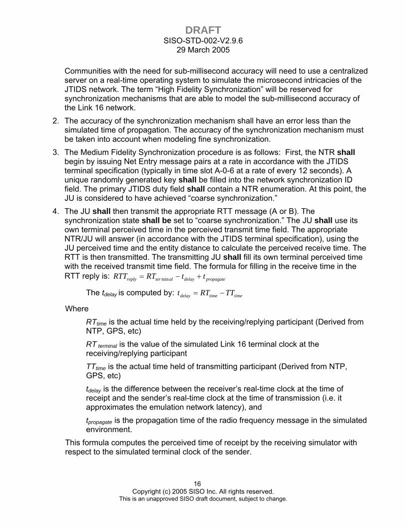
4. The JU shall then transmit the appropriate RTT message (A or B). The synchronization state shall be set to “coarse synchronization.” The JU shall use its own terminal perceived time in the perceived transmit time field. The appropriate NTR/JU will answer (in accordance with the JTIDS terminal specification), using the JU perceived time and the entity distance to calculate the perceived receive time. The RTT is then transmitted. The transmitting JU shall fill its own terminal perceived time with the received transmit time field. The formula for filling in the receive time in the RTT reply is: propagatedelayalterreply ttRTRTT +−= min
The tdelay is computed by: timetimedelay TTRTt −=
Where RTtime is the actual time held by the receiving/replying participant (Derived from NTP, GPS, etc) RT terminal is the value of the simulated Link 16 terminal clock at the receiving/replying participant TTtime is the actual time held of transmitting participant (Derived from NTP, GPS, etc) tdelay is the difference between the receiver’s real-time clock at the time of receipt and the sender’s real-time clock at the time of transmission (i.e. it approximates the emulation network latency), and tpropagate is the propagation time of the radio frequency message in the simulated environment.
This formula computes the perceived time of receipt by the receiving simulator with respect to the simulated terminal clock of the sender.

DRAFT SISO-STD-002-V2.9.6
29 March 2005
17 Copyright (c) 2005 SISO Inc. All rights reserved.
This is an unapproved SISO draft document, subject to change.
5. The originating JU shall then update its own terminal time in accordance with the simulator model and the Link 16 fine synchronization procedures. After the appropriate number of RTT exchanges have occurred (depending whether the RTT A or RTT B method of synchronization was used and the internal terminal simulation model), the JU shall consider itself to be in fine synchronization and shall continually issue RTT message pairs to maintain synchronization at rates specified within the JTIDS terminal specification. Once the terminal emulator model has met the requirements for fine synchronization, normal message transmissions occur in accordance with Ref. 7 and Ref. 10.
5.2 JTIDS IMPLEMENTATION UNDER DIS This section contains the requirements for simulation of JTIDS using the DIS Signal and Transmitter PDU. For the DIS Protocol Profiles, transmission and receipt of PDUs, and general service requirements, refer to Reference 1. In implementing the Signal PDU, perceived data should be able to be sent on a configurable port separate from all other DIS data. This allows datalinks to be selectively routed without additional hardware. This also allows for gateways to forward data between legacy DIS datalink formats and the new standardized format.
5.2.1 Transmitter PDU Description Table 5.2.1 shows the format for the Transmitter PDU for JTIDS simulation. Examples of the Transmitter PDU for TSA Levels 0-3 are found in Annex B. Transmitter PDUs used in Link 16 simulation shall include all of the standard information, as well as the information described in the modulation fields. The Transmitter PDU shall contain the following fields:
1. The Radio Entity Type Category field shall be set to 21 for Link 16 terminal. 2. The Input Source field shall be set to 8 for Digital Data Device. 3. Frequency. This field shall specify the JTIDS center frequency of 1131000000 for
communications mode 1. For communications mode 2 or 4, a frequency of 969000000 shall be used.
4. Transmit Frequency Bandwidth. This field shall contain the bandwidth of the JTIDS signal, simulating the use of the entire frequency band as an average over time. The field shall be represented by a 32-bit float value of 240000000, unless operating in communications mode 2 or 4, and then a value of 3000000 shall be used.
5. Modulation Type. The Modulation Type fields contain enumerations for the major and detail modulation fields: a. The Spread Spectrum field is a 16-bit Boolean array, and shall be set to 1 for
frequency hopping only for JTIDS communications mode 1. For modes 2 or 4, the Spread Spectrum field shall be set to 0.
DRAFT SISO-STD-002-V2.9.6
29 March 2005
18 Copyright (c) 2005 SISO Inc. All rights reserved.
This is an unapproved SISO draft document, subject to change.
b. The Major modulation field is a 16-bit enumeration, and shall be set to 7 for Carrier Phase Shift Modulation.
c. The Detail modulation field is a 16-bit enumeration, and shall contain a 0. d. The System field is a 16-bit enumeration, and shall be set to 8 for JTIDS/MIDS
6. Crypto System. For Link 16 simulation under this standard this field shall be set to zero.
7. Crypto Key ID. For Link 16 simulation under this standard this field shall be set to zero.
8. Length of Modulation Parameters. These fields shall specify the length in octets of the modulation parameters that follow this field. This length shall be set to 8, representing 8 octets for the DIS J Transmitter PDU.
9. Modulation Parameters. These fields shall specify the modulation type specific characteristics of the Transmitter PDU. a. Modulation Parameter 1 shall contain the TSA mode with an enumeration of 0-4
for TSA level 0-4 as described in section 5.1.2. b. Modulation Parameter 2 shall contain the transmitting terminal’s primary mode.
Setting the enumeration to 1 shall indicate that the entity is the NTR. Setting it to 2 shall indicate that the entity is a JU participant.
c. Modulation Parameter 3 shall contain the transmitting terminal’s secondary mode, with the following enumerations: 0=None, 1=Net Position Reference, 2=Primary Navigation Controller, 3=Secondary Navigation Controller.
d. Modulation Parameter 4 shall contain the synchronization state. For TSA mode level 0-3 this shall be set to 3 for “fine” synchronization. For TSA level 4, it is initially set to 2 for “coarse” synchronization and the procedures in section 5.1.4.2 for medium-level synchronization are followed.
e. Modulation Parameter 5 shall contain the Network Synchronization ID. For TSA modes 0-2, it shall be set to zero. For TSA modes 3-4, it shall be a 32-bit random integer. Only an NTR can generate a Network Synchronization ID; all other participants shall use the ID obtained from the NTR to which they are synchronized.
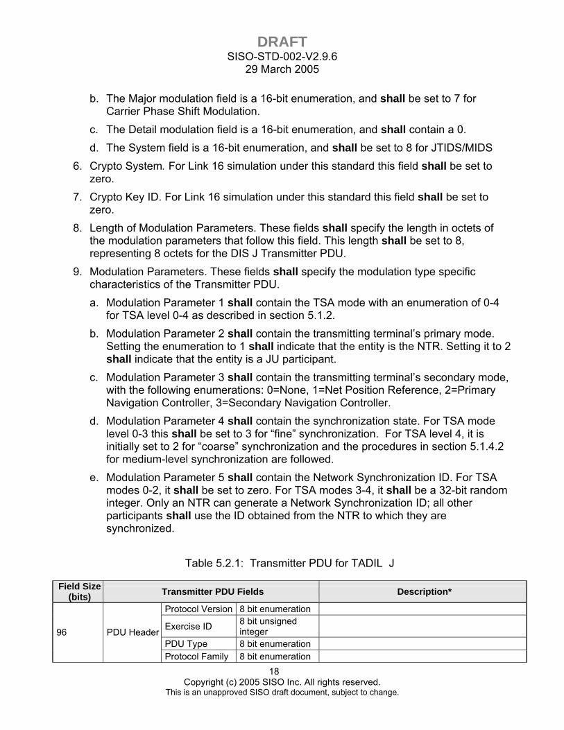
Table 5.2.1: Transmitter PDU for TADIL J
Field Size (bits) Transmitter PDU Fields Description*
Protocol Version 8 bit enumeration
Exercise ID 8 bit unsigned integer
PDU Type 8 bit enumeration 96 PDU Header
Protocol Family 8 bit enumeration
DRAFT SISO-STD-002-V2.9.6
29 March 2005
19 Copyright (c) 2005 SISO Inc. All rights reserved.
This is an unapproved SISO draft document, subject to change.
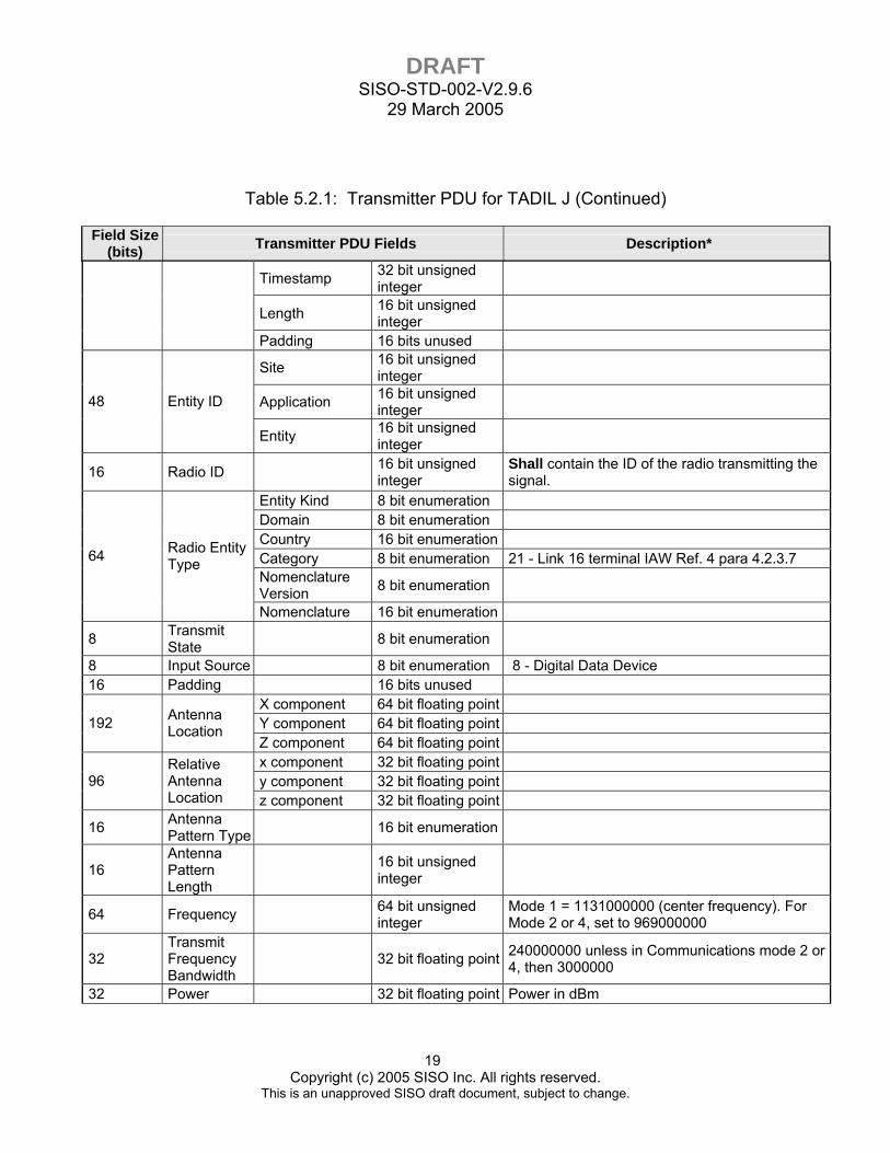
Table 5.2.1: Transmitter PDU for TADIL J (Continued)
Field Size (bits) Transmitter PDU Fields Description*
Timestamp 32 bit unsigned integer
Length 16 bit unsigned integer
Padding 16 bits unused
Site 16 bit unsigned integer
Application 16 bit unsigned integer 48 Entity ID
Entity 16 bit unsigned integer
16 Radio ID 16 bit unsigned integer
Shall contain the ID of the radio transmitting the signal.
Entity Kind 8 bit enumeration Domain 8 bit enumeration Country 16 bit enumeration Category 8 bit enumeration 21 - Link 16 terminal IAW Ref. 4 para 4.2.3.7 Nomenclature Version 8 bit enumeration
64 Radio Entity Type
Nomenclature 16 bit enumeration
8 Transmit State 8 bit enumeration
8 Input Source 8 bit enumeration 8 - Digital Data Device 16 Padding 16 bits unused
X component 64 bit floating point Y component 64 bit floating point 192 Antenna
Location Z component 64 bit floating point x component 32 bit floating point y component 32 bit floating point 96
Relative Antenna Location z component 32 bit floating point
16 Antenna Pattern Type 16 bit enumeration
16 Antenna Pattern Length
16 bit unsigned integer
64 Frequency 64 bit unsigned integer
Mode 1 = 1131000000 (center frequency). For Mode 2 or 4, set to 969000000
32 Transmit Frequency Bandwidth
32 bit floating point 240000000 unless in Communications mode 2 or 4, then 3000000
32 Power 32 bit floating point Power in dBm
DRAFT SISO-STD-002-V2.9.6
29 March 2005
20 Copyright (c) 2005 SISO Inc. All rights reserved.
This is an unapproved SISO draft document, subject to change.
Table 5.2.1: Transmitter PDU for TADIL J (Continued)
Field Size (bits) Transmitter PDU Fields Description*
Spread Spectrum
16 bit Boolean array
Bit 1 set to 1: Frequency Hopping for JTIDS communications mode 1. All bits set to 0: For JTIDS communications modes 2 or 4
Major 16 bit enumeration 7 - Carrier Phase Shift Modulation (CPSM)
Detail 16 bit enumeration 0 - Other
64 Modulation Type
System 16 bit enumeration 8 - JTIDS/MIDS
16 Crypto System 16 bit enumeration 0 - Other
16 Crypto Key ID 16 bit unsigned
integer
8 Length of Modulation Parameters
8 bit unsigned integer 8= 8 octets
24 Padding 24 bits unused
8 Modulation Parameter #1
Time Slot Allocation Mode 8 bit enumeration Integer enumeration 0-4
8 Modulation Parameter #2
Transmitting Terminal Primary Mode
8 bit enumeration Integer Enumeration: 1 - NTR 2 - JTIDS Unit Participant
8 Modulation Parameter #3
Transmitting Terminal Secondary Mode
8 bit enumeration
Integer Enumeration: 0 - None 1 - Net Position Reference 2 - Primary Navigation Controller 3 - Secondary Navigation Controller
8 Modulation Parameter #4
Synchronization State 8 bit enumeration
Integer Enumeration: 2 - Coarse Synchronization 3 - Fine Synchronization
32 Modulation Parameter #5
Network Synchronization ID
32 bit unsigned integer
TSA Level 0-2, set to 0 TSA Level 3,4, set to 32 bit random number
*If blank, IAW Ref. 1 and Ref. 4
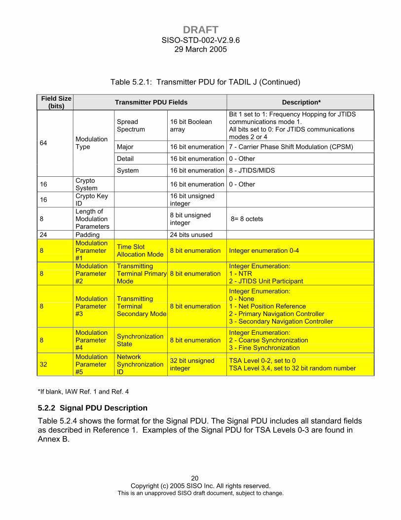
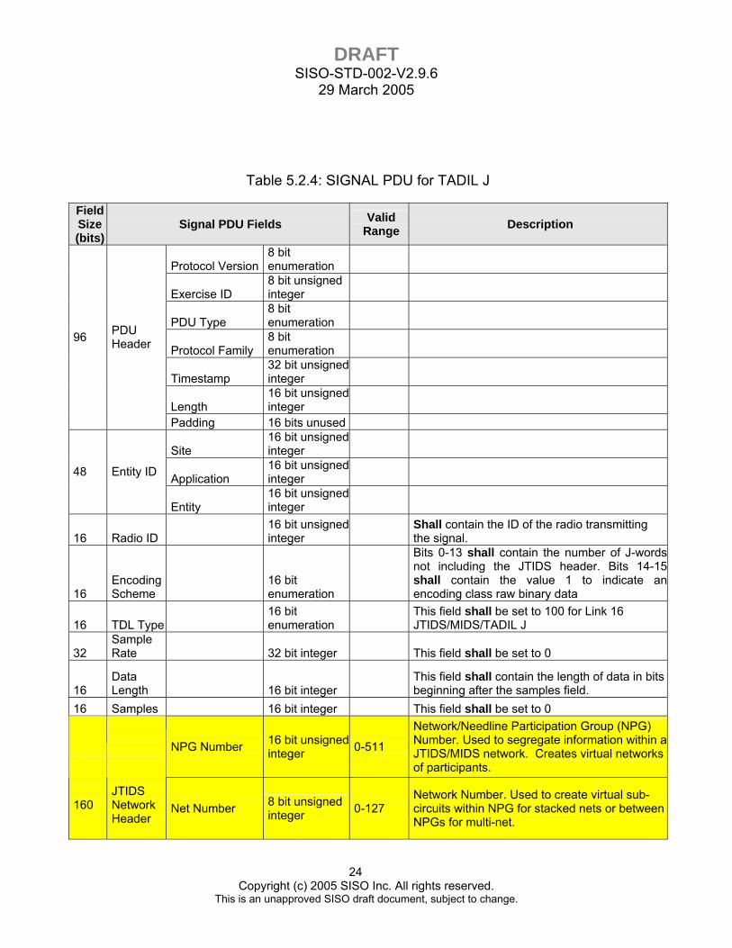
5.2.2 Signal PDU Description Table 5.2.4 shows the format for the Signal PDU. The Signal PDU includes all standard fields as described in Reference 1. Examples of the Signal PDU for TSA Levels 0-3 are found in Annex B.
DRAFT SISO-STD-002-V2.9.6
29 March 2005
21 Copyright (c) 2005 SISO Inc. All rights reserved.
This is an unapproved SISO draft document, subject to change.
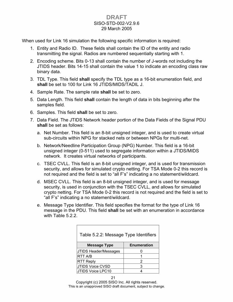
When used for Link 16 simulation the following specific information is required: 1. Entity and Radio ID. These fields shall contain the ID of the entity and radio
transmitting the signal. Radios are numbered sequentially starting with 1. 2. Encoding scheme. Bits 0-13 shall contain the number of J-words not including the
JTIDS header. Bits 14-15 shall contain the value 1 to indicate an encoding class raw binary data.
3. TDL Type. This field shall specify the TDL type as a 16-bit enumeration field, and shall be set to 100 for Link 16 JTIDS/MIDS/TADIL J.
4. Sample Rate. The sample rate shall be set to zero. 5. Data Length. This field shall contain the length of data in bits beginning after the
samples field. 6. Samples. This field shall be set to zero. 7. Data Field. The JTIDS Network header portion of the Data Fields of the Signal PDU
shall be set as follows: a. Net Number. This field is an 8-bit unsigned integer, and is used to create virtual
sub-circuits within NPG for stacked nets or between NPGs for multi-net. b. Network/Needline Participation Group (NPG) Number. This field is a 16-bit
unsigned integer (0-511) used to segregate information within a JTIDS/MIDS network. It creates virtual networks of participants.
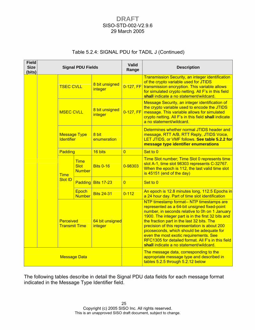
c. TSEC CVLL. This field is an 8-bit unsigned integer, and is used for transmission security, and allows for simulated crypto netting. For TSA Mode 0-2 this record is not required and the field is set to “all F’s” indicating a no statement/wildcard.
d. MSEC CVLL. This field is an 8-bit unsigned integer, and is used for message security, is used in conjunction with the TSEC CVLL, and allows for simulated crypto netting. For TSA Mode 0-2 this record is not required and the field is set to “all F’s” indicating a no statement/wildcard.
e. Message Type Identifier. This field specifies the format for the type of Link 16 message in the PDU. This field shall be set with an enumeration in accordance with Table 5.2.2.
Table 5.2.2: Message Type Identifiers
Message Type Enumeration JTIDS Header/Messages 0 RTT A/B 1 RTT Reply 2 JTIDS Voice CVSD 3 JTIDS Voice LPC10 4
DRAFT SISO-STD-002-V2.9.6
29 March 2005
22 Copyright (c) 2005 SISO Inc. All rights reserved.
This is an unapproved SISO draft document, subject to change.
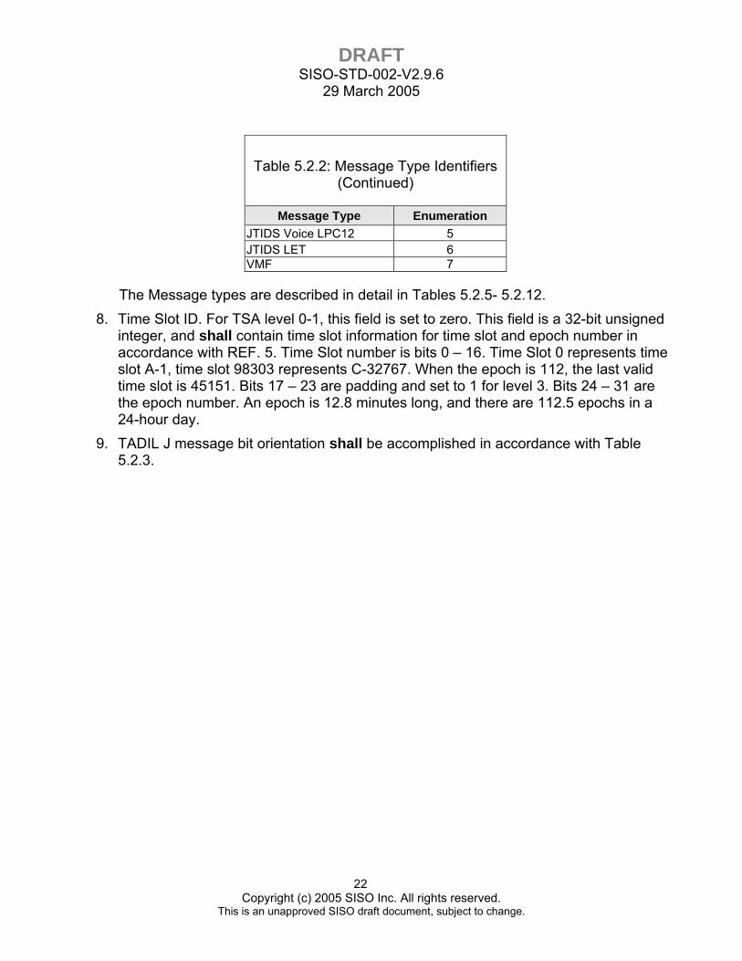
Table 5.2.2: Message Type Identifiers (Continued)
Message Type Enumeration JTIDS Voice LPC12 5 JTIDS LET 6 VMF 7
The Message types are described in detail in Tables 5.2.5- 5.2.12. 8. Time Slot ID. For TSA level 0-1, this field is set to zero. This field is a 32-bit unsigned
integer, and shall contain time slot information for time slot and epoch number in accordance with REF. 5. Time Slot number is bits 0 – 16. Time Slot 0 represents time slot A-1, time slot 98303 represents C-32767. When the epoch is 112, the last valid time slot is 45151. Bits 17 – 23 are padding and set to 1 for level 3. Bits 24 – 31 are the epoch number. An epoch is 12.8 minutes long, and there are 112.5 epochs in a 24-hour day.
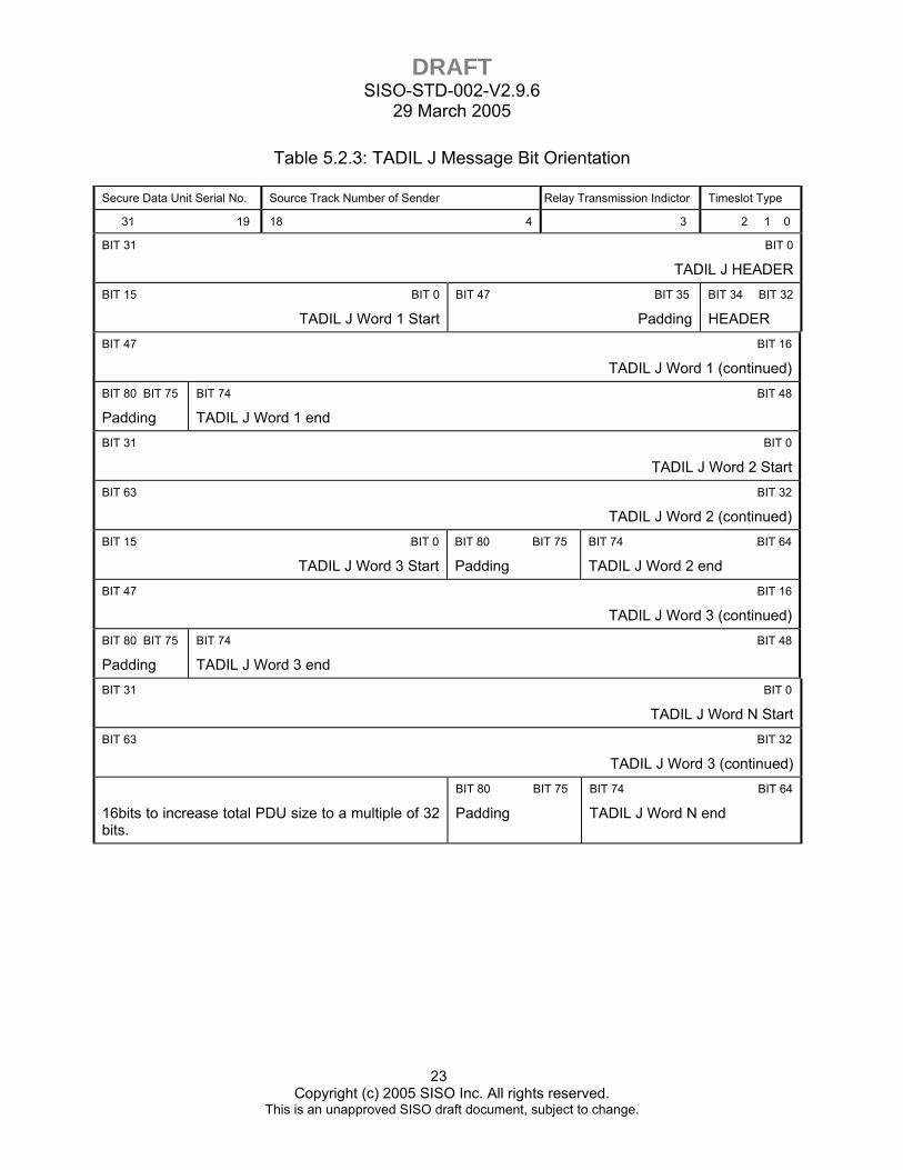
9. TADIL J message bit orientation shall be accomplished in accordance with Table 5.2.3.
DRAFT SISO-STD-002-V2.9.6
29 March 2005
23 Copyright (c) 2005 SISO Inc. All rights reserved.
This is an unapproved SISO draft document, subject to change.
Table 5.2.3: TADIL J Message Bit Orientation
Secure Data Unit Serial No. Source Track Number of Sender Relay Transmission Indictor Timeslot Type
31 19 18 4 3 2 1 0
BIT 31 BIT 0
TADIL J HEADERBIT 15 BIT 0
TADIL J Word 1 Start
BIT 47 BIT 35
Padding
BIT 34 BIT 32
HEADER BIT 47 BIT 16
TADIL J Word 1 (continued)BIT 80 BIT 75
Padding
BIT 74 BIT 48
TADIL J Word 1 end BIT 31 BIT 0
TADIL J Word 2 StartBIT 63 BIT 32
TADIL J Word 2 (continued)BIT 15 BIT 0
TADIL J Word 3 Start
BIT 80 BIT 75
Padding
BIT 74 BIT 64
TADIL J Word 2 end BIT 47 BIT 16
TADIL J Word 3 (continued)BIT 80 BIT 75
Padding
BIT 74 BIT 48
TADIL J Word 3 end BIT 31 BIT 0
TADIL J Word N Start BIT 63 BIT 32
TADIL J Word 3 (continued)
16bits to increase total PDU size to a multiple of 32 bits.
BIT 80 BIT 75
Padding
BIT 74 BIT 64
TADIL J Word N end
DRAFT SISO-STD-002-V2.9.6
29 March 2005
24 Copyright (c) 2005 SISO Inc. All rights reserved.
This is an unapproved SISO draft document, subject to change.
Table 5.2.4: SIGNAL PDU for TADIL J
Field Size (bits)
Signal PDU Fields Valid Range Description
Protocol Version 8 bit enumeration
Exercise ID 8 bit unsigned integer
PDU Type 8 bit enumeration
Protocol Family 8 bit enumeration
Timestamp 32 bit unsigned integer
Length 16 bit unsigned integer
96 PDU Header
Padding 16 bits unused
Site 16 bit unsigned integer
Application 16 bit unsigned integer 48 Entity ID
Entity 16 bit unsigned integer
16 Radio ID 16 bit unsigned integer
Shall contain the ID of the radio transmitting the signal.
16 Encoding Scheme
16 bit enumeration
Bits 0-13 shall contain the number of J-words not including the JTIDS header. Bits 14-15 shall contain the value 1 to indicate an encoding class raw binary data
16 TDL Type 16 bit enumeration
This field shall be set to 100 for Link 16 JTIDS/MIDS/TADIL J
32 Sample Rate 32 bit integer This field shall be set to 0
16 Data Length 16 bit integer
This field shall contain the length of data in bits beginning after the samples field.
16 Samples 16 bit integer This field shall be set to 0
NPG Number 16 bit unsigned integer 0-511
Network/Needline Participation Group (NPG) Number. Used to segregate information within a JTIDS/MIDS network. Creates virtual networks of participants.
160
JTIDS Network Header
Net Number 8 bit unsigned integer 0-127
Network Number. Used to create virtual sub-circuits within NPG for stacked nets or between NPGs for multi-net.
DRAFT SISO-STD-002-V2.9.6
29 March 2005
25 Copyright (c) 2005 SISO Inc. All rights reserved.
This is an unapproved SISO draft document, subject to change.
Table 5.2.4: SIGNAL PDU for TADIL J (Continued)
Field Size (bits)
Signal PDU Fields Valid Range Description
TSEC CVLL 8 bit unsigned integer 0-127, FF
Transmission Security, an integer identification of the crypto variable used for JTIDS transmission encryption. This variable allows for simulated crypto netting. All F’s in this field shall indicate a no statement/wildcard.
MSEC CVLL 8 bit unsigned integer 0-127, FF
Message Security, an integer identification of the crypto variable used to encode the JTIDS message. This variable allows for simulated crypto netting. All F’s in this field shall indicate a no statement/wildcard.
Message Type Identifier
8 bit enumeration
Determines whether normal JTIDS header and message, RTT A/B, RTT Reply, JTIDS Voice, LET JTIDS, or VMF follows. See table 5.2.2 for message type identifier enumerations
Padding 16 bits 0 Set to 0
Time Slot Number
Bits 0-16 0-98303
Time Slot number; Time Slot 0 represents time slot A-1, time slot 98303 represents C-32767. When the epoch is 112, the last valid time slot is 45151 (end of the day)
Padding Bits 17-23 0 Set to 0
Time Slot ID
Epoch Number Bits 24-31 0-112 An epoch is 12.8 minutes long, 112.5 Epochs in
a 24 hour day. Part of time slot identification
Perceived Transmit Time
64 bit unsigned integer
NTP timestamp format-- NTP timestamps are represented as a 64-bit unsigned fixed-point number, in seconds relative to 0h on 1 January 1900. The integer part is in the first 32 bits and the fraction part in the last 32 bits. The precision of this representation is about 200 picoseconds, which should be adequate for even the most exotic requirements. See RFC1305 for detailed format. All F’s in this field shall indicate a no statement/wildcard.
Message Data The message data, corresponding to the appropriate message type and described in tables 5.2.5 through 5.2.12 below
The following tables describe in detail the Signal PDU data fields for each message format indicated in the Message Type Identifier field.

DRAFT SISO-STD-002-V2.9.6
29 March 2005
26 Copyright (c) 2005 SISO Inc. All rights reserved.
This is an unapproved SISO draft document, subject to change.
Table 5.2.5: Message Type = 0, JTIDS Header/Message
Field Size (bits) Signal PDU Fields Bits Description
Time Slot Type Bits 0-2 Ref. 7, Table 3.3-7
Relay Transmission Indicator
Bit 3 Ref. 7, Table 3.3-6
Source Track Number of Sender
Bits 4-18 Ref. 7, Table 3.3-6
Secure Data Unit Serial Number Bits 19-34 Ref. 7, Table 3.3-6
48 JTIDS Header
Padding Bits 35-47
TADIL J Word 75 Bits Ref. 7 80 TADIL J
Word #1 Padding 5 Bits TADIL J Word 75 Bits Ref. 7
80
TADIL J Word #N (to maximum number of messages)
Padding 5 Bits
Signal PDU C2 Padding to doubleword boundary IAW Ref. 1 Padding (if needed) to increase total PDU size to a
multiple of 32 bits..
Table 5.2.6: Message Type = 1, RTT A/B
Field Size (bits) Signal PDU Fields Bits Description
48 RTT A/B RTT A/B Bits 0-34 Ref. 5, Table 3.3-8
(Used in place of JTIDS header during RTT transmission)
Padding Bits 35-47
16 Signal PDU C2 Padding to doubleword boundary IAW Ref. 1
16bits to increase total PDU size to a multiple of 32 bits.
DRAFT SISO-STD-002-V2.9.6
29 March 2005
27 Copyright (c) 2005 SISO Inc. All rights reserved.
This is an unapproved SISO draft document, subject to change.
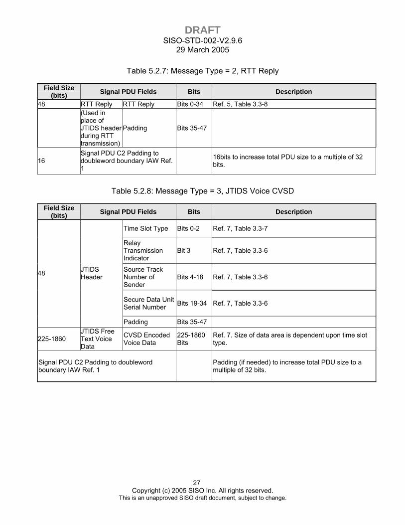
Table 5.2.7: Message Type = 2, RTT Reply
Field Size (bits) Signal PDU Fields Bits Description
48 RTT Reply RTT Reply Bits 0-34 Ref. 5, Table 3.3-8
(Used in place of JTIDS header during RTT transmission)
Padding Bits 35-47
16 Signal PDU C2 Padding to doubleword boundary IAW Ref. 1
16bits to increase total PDU size to a multiple of 32 bits.
Table 5.2.8: Message Type = 3, JTIDS Voice CVSD
Field Size (bits) Signal PDU Fields Bits Description
Time Slot Type Bits 0-2 Ref. 7, Table 3.3-7
Relay Transmission Indicator
Bit 3 Ref. 7, Table 3.3-6
Source Track Number of Sender
Bits 4-18 Ref. 7, Table 3.3-6
Secure Data Unit Serial Number Bits 19-34 Ref. 7, Table 3.3-6
48 JTIDS Header
Padding Bits 35-47
225-1860 JTIDS Free Text Voice Data
CVSD Encoded Voice Data
225-1860 Bits
Ref. 7. Size of data area is dependent upon time slot type.
Signal PDU C2 Padding to doubleword boundary IAW Ref. 1 Padding (if needed) to increase total PDU size to a
multiple of 32 bits.
DRAFT SISO-STD-002-V2.9.6
29 March 2005
28 Copyright (c) 2005 SISO Inc. All rights reserved.
This is an unapproved SISO draft document, subject to change.
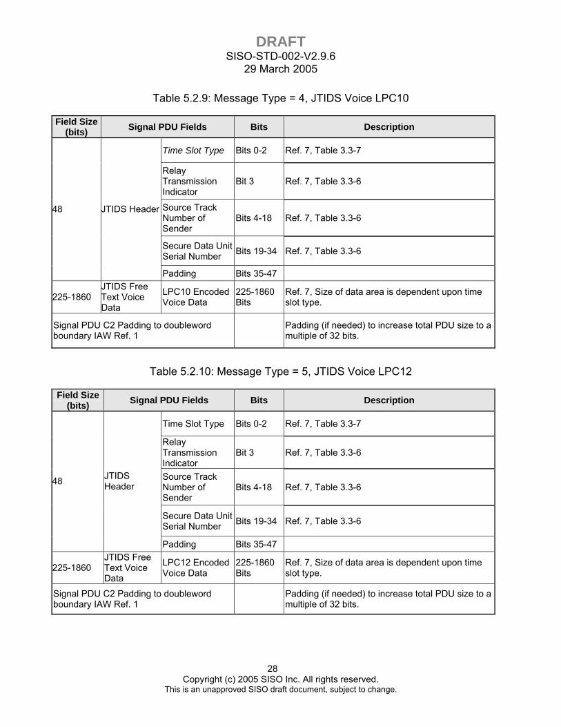
Table 5.2.9: Message Type = 4, JTIDS Voice LPC10
Field Size (bits) Signal PDU Fields Bits Description
Time Slot Type Bits 0-2 Ref. 7, Table 3.3-7
Relay Transmission Indicator
Bit 3 Ref. 7, Table 3.3-6
Source Track Number of Sender
Bits 4-18 Ref. 7, Table 3.3-6
Secure Data Unit Serial Number Bits 19-34 Ref. 7, Table 3.3-6
48 JTIDS Header
Padding Bits 35-47
225-1860 JTIDS Free Text Voice Data
LPC10 Encoded Voice Data
225-1860 Bits
Ref. 7, Size of data area is dependent upon time slot type.
Signal PDU C2 Padding to doubleword boundary IAW Ref. 1 Padding (if needed) to increase total PDU size to a
multiple of 32 bits.
Table 5.2.10: Message Type = 5, JTIDS Voice LPC12
Field Size (bits) Signal PDU Fields Bits Description
Time Slot Type Bits 0-2 Ref. 7, Table 3.3-7
Relay Transmission Indicator
Bit 3 Ref. 7, Table 3.3-6
Source Track Number of Sender
Bits 4-18 Ref. 7, Table 3.3-6
Secure Data Unit Serial Number Bits 19-34 Ref. 7, Table 3.3-6
48 JTIDS Header
Padding Bits 35-47
225-1860 JTIDS Free Text Voice Data
LPC12 Encoded Voice Data
225-1860 Bits
Ref. 7, Size of data area is dependent upon time slot type.
Signal PDU C2 Padding to doubleword boundary IAW Ref. 1 Padding (if needed) to increase total PDU size to a
multiple of 32 bits.
DRAFT SISO-STD-002-V2.9.6
29 March 2005
29 Copyright (c) 2005 SISO Inc. All rights reserved.
This is an unapproved SISO draft document, subject to change.
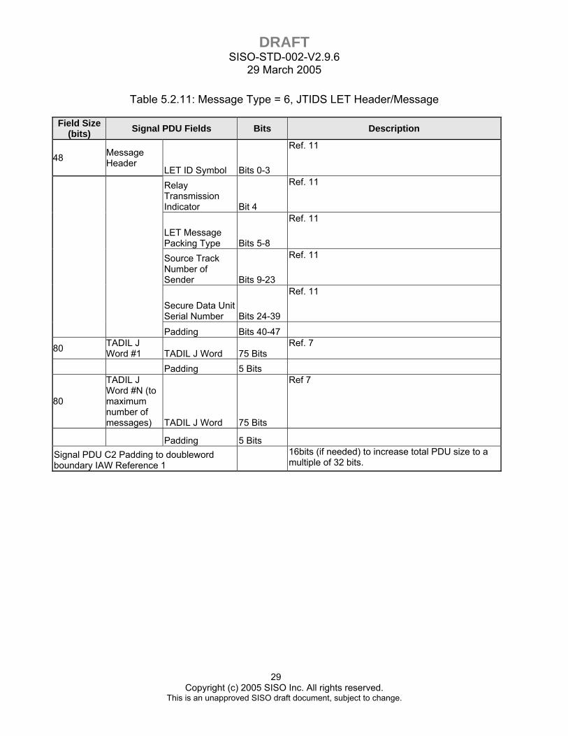
Table 5.2.11: Message Type = 6, JTIDS LET Header/Message
Field Size (bits) Signal PDU Fields Bits Description
48 Message Header
LET ID Symbol Bits 0-3
Ref. 11
Relay Transmission Indicator Bit 4
Ref. 11
LET Message Packing Type Bits 5-8
Ref. 11
Source Track Number of Sender Bits 9-23
Ref. 11
Secure Data Unit Serial Number Bits 24-39
Ref. 11
Padding Bits 40-47
80 TADIL J Word #1 TADIL J Word 75 Bits
Ref. 7
Padding 5 Bits
80
TADIL J Word #N (to maximum number of messages) TADIL J Word 75 Bits
Ref 7
Padding 5 Bits
Signal PDU C2 Padding to doubleword boundary IAW Reference 1
16bits (if needed) to increase total PDU size to a multiple of 32 bits.
DRAFT SISO-STD-002-V2.9.6
29 March 2005
30 Copyright (c) 2005 SISO Inc. All rights reserved.
This is an unapproved SISO draft document, subject to change.
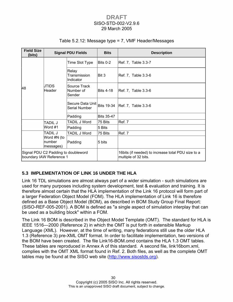
Table 5.2.12: Message type = 7, VMF Header/Messages
Field Size (bits) Signal PDU Fields Bits Description
Time Slot Type Bits 0-2 Ref. 7, Table 3.3-7
Relay Transmission Indicator
Bit 3 Ref. 7, Table 3.3-6
Source Track Number of Sender
Bits 4-18 Ref. 7, Table 3.3-6
Secure Data Unit Serial Number Bits 19-34 Ref. 7, Table 3.3-6
48 JTIDS Header
Padding Bits 35-47 TADIL J Word 75 Bits Ref. 7
TADIL J Word #1 Padding 5 Bits
TADIL J Word 75 Bits Ref. 7
TADIL J Word #N (to number messages)
Padding 5 bits
Signal PDU C2 Padding to doubleword boundary IAW Reference 1 16bits (if needed) to increase total PDU size to a
multiple of 32 bits.
5.3 IMPLEMENTATION OF LINK 16 UNDER THE HLA Link 16 TDL simulations are almost always part of a wider simulation - such simulations are used for many purposes including system development, test & evaluation and training. It is therefore almost certain that the HLA implementation of the Link 16 protocol will form part of a larger Federation Object Model (FOM). The HLA implementation of Link 16 is therefore defined as a Base Object Model (BOM), as described in BOM Study Group Final Report: (SISO-REF-005-2001). A BOM is defined as "a single aspect of simulation interplay that can be used as a building block" within a FOM. The Link 16 BOM is described in the Object Model Template (OMT). The standard for HLA is IEEE 1516—2000 (Reference 2) in which the OMT is put forth in extensible Markup Language (XML). However, at the time of writing, many federations still use the older HLA 1.3 (Reference 3) pre-XML OMT format. In order to facilitate implementation, two versions of the BOM have been created. The file Link16-BOM.omd contains the HLA 1.3 OMT tables. These tables are reproduced in Annex A of this standard. A second file, link16bom.xml, complies with the OMT XML format found in Ref. 2. Both files, as well as the complete OMT tables may be found at the SISO web site (http://www.sisostds.org).
DRAFT SISO-STD-002-V2.9.6
29 March 2005
31 Copyright (c) 2005 SISO Inc. All rights reserved.
This is an unapproved SISO draft document, subject to change.
5.3.1 The Link 16 BOM The Link 16 BOM is intended to describe how to implement a simulation of the Link 16 Tactical Data Link (TDL) and its associated message set, TADIL J, within a High Level Architecture (HLA) simulation. The Link 16 BOM is designed for integration within the Federation Object Model (FOM) of the HLA federation.
5.3.1.1 Assumptions The Link 16 BOM assumes that:
1. The parent FOM contains all current DIS Transmitter PDU parameters as part of its object class hierarchy.
2. The parent FOM contains all current DIS Signal PDU parameters as part of its interaction class hierarchy.
5.3.1.2 Naming Convention Conventions within the Link 16 BOM in OMT 1.3 format follow those adopted by the RPR FOM. These conventions are intended to address some of the OMT 1.3 format shortcomings, which have been addressed in the IEEE 1516.2 specification. These include:
1. All names have the initial letter of each word capitalized. 2. All enumeration names end in the text "Enum" followed by a number. The number
indicates the number of bits in the enumerated value. 3. All complex data type names end in the text "Struct".
5.3.2 Levels of Fidelity The HLA levels of fidelity are directly equivalent to the corresponding DIS levels of fidelity as defined in section 5.1.2.
5.3.3 Time Synchronization The HLA time synchronization mechanism is directly equivalent to the corresponding mechanism for DIS as defined in section 5.1.
5.3.4 Protocol Implementation Details This section defines how Link 16 BOM compliant federates are to implement the Link 16 protocol. The HLA protocol implementation details are directly equivalent to the corresponding details for DIS as defined in section 5.2.
DRAFT SISO-STD-002-V2.9.6
29 March 2005
32 Copyright (c) 2005 SISO Inc. All rights reserved.
This is an unapproved SISO draft document, subject to change.
5.3.4.1 Object Class Data The Link 16 BOM defines no new object classes. Instead the BOM defines a single complex data type (JTIDSTransmitterStruct) that corresponds to the modulation parameters in the DIS Transmitter PDU defined in section 5.2.1. An attribute of this complex data type should be added to the object class in the parent FOM corresponding to the DIS Transmitter PDU (see assumption 1 in section 5.3.1) Modulation parameters of the Transmitter PDU shown in section 5.2, table 5.2.1, map to the fields of the JTIDSTransmitterStruct complex data type attribute, shown in Annex A.5.
Parent object class fields are also modified such that they refer to the corresponding Transmitter PDU fields (see Assumption 1 in section 5.3.1).
NOTE: For a RPR FOM implementation, an attribute of the JTIDSTransmitterStruct complex data type should be added to the RadioTransmitter object class.
5.3.4.2 Interaction Class Data The Link 16 BOM adds a family of interactions that will support future TDL implementation of other datalinks. The family of interactions is a hierarchy in which the BOM’s base class for this interaction is a generic class - the TDLBinaryRadioSignal interaction. This class is an empty class, contains no parameters, and is neither publishable nor subscribable. The specific parameters are properties of the various subclasses of this generic base class, and it is these subclasses that are published and subscribed to.
The Link16RadioSignal interaction, shown in Annex A.3, which is a subclass of the TDLBinaryRadioSignal interaction, contains the JTIDS Network Header Parameters as shown in table 5.2.4. The JTIDSMessageRadioSignal interaction contains the Link 16 message data. Additional interactions shown in Annex A.3 define the other types of Link 16 messages. Parent object class fields are also modified such that they refer to the corresponding Signal PDU fields (see Assumption 1 in section 5.3.1).
The Link 16 BOM design is such that the TDLBinaryRadioSignal interaction becomes a subclass of the parent FOM's equivalent of the DIS Signal PDU (see Assumption 2 in section 5.3.1). Modulation parameters of the Signal PDU map to the fields of the JTIDSTransmitterStruct complex data type attribute (see section 5.2). Parent object class fields are also modified such that they refer to the corresponding Signal PDU fields (see Assumption 1 in section 5.3.1).
NOTE: For a RPR FOM implementation, the TDLBinaryRadioSignal class becomes a subclass of the RPR FOM RawBinaryRadioSignal interaction class; this is done in order to allow access to the HostRadioIndex parameter in the RawBinaryRadioSignal interaction class. The HostRadioIndex parameter ties the Link 16 message to a specific Host and Radio Transmitter.
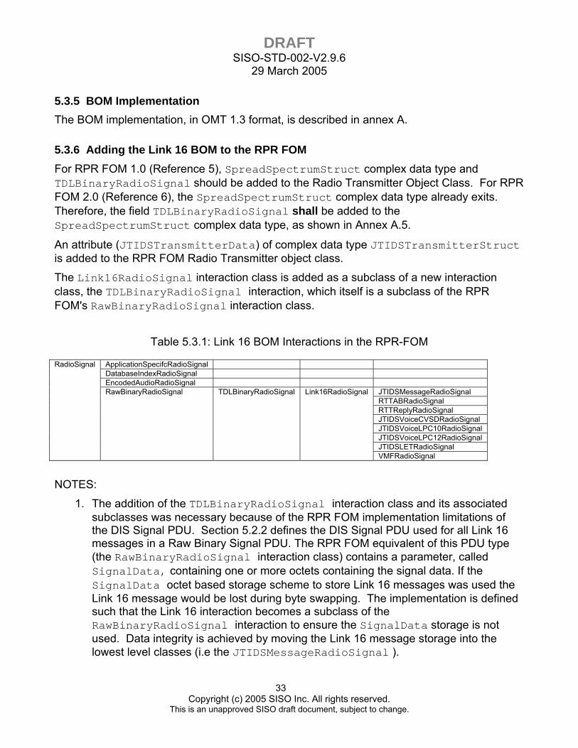
DRAFT SISO-STD-002-V2.9.6
29 March 2005
33 Copyright (c) 2005 SISO Inc. All rights reserved.
This is an unapproved SISO draft document, subject to change.
5.3.5 BOM Implementation The BOM implementation, in OMT 1.3 format, is described in annex A.
5.3.6 Adding the Link 16 BOM to the RPR FOM For RPR FOM 1.0 (Reference 5), SpreadSpectrumStruct complex data type and TDLBinaryRadioSignal should be added to the Radio Transmitter Object Class. For RPR FOM 2.0 (Reference 6), the SpreadSpectrumStruct complex data type already exits. Therefore, the field TDLBinaryRadioSignal shall be added to the SpreadSpectrumStruct complex data type, as shown in Annex A.5.
An attribute (JTIDSTransmitterData) of complex data type JTIDSTransmitterStruct is added to the RPR FOM Radio Transmitter object class.
The Link16RadioSignal interaction class is added as a subclass of a new interaction class, the TDLBinaryRadioSignal interaction, which itself is a subclass of the RPR FOM's RawBinaryRadioSignal interaction class.
Table 5.3.1: Link 16 BOM Interactions in the RPR-FOM
ApplicationSpecifcRadioSignal DatabaseIndexRadioSignal EncodedAudioRadioSignal
JTIDSMessageRadioSignal RTTABRadioSignal RTTReplyRadioSignal JTIDSVoiceCVSDRadioSignal JTIDSVoiceLPC10RadioSignal JTIDSVoiceLPC12RadioSignal JTIDSLETRadioSignal
RadioSignal
RawBinaryRadioSignal TDLBinaryRadioSignal Link16RadioSignal
VMFRadioSignal
NOTES:
1. The addition of the TDLBinaryRadioSignal interaction class and its associated subclasses was necessary because of the RPR FOM implementation limitations of the DIS Signal PDU. Section 5.2.2 defines the DIS Signal PDU used for all Link 16 messages in a Raw Binary Signal PDU. The RPR FOM equivalent of this PDU type (the RawBinaryRadioSignal interaction class) contains a parameter, called SignalData, containing one or more octets containing the signal data. If the SignalData octet based storage scheme to store Link 16 messages was used the Link 16 message would be lost during byte swapping. The implementation is defined such that the Link 16 interaction becomes a subclass of the RawBinaryRadioSignal interaction to ensure the SignalData storage is not used. Data integrity is achieved by moving the Link 16 message storage into the lowest level classes (i.e the JTIDSMessageRadioSignal ).

DRAFT SISO-STD-002-V2.9.6
29 March 2005
34 Copyright (c) 2005 SISO Inc. All rights reserved.
This is an unapproved SISO draft document, subject to change.
2. DIS to HLA gateways will require modification, but the modifications are well defined. DIS Raw Binary Signal PDUs need to be split into a RawBinaryRadioSignal interaction or the appropriate Link 16 interaction class, depending on the TDL type. Conversely, a HLA to DIS gateway must merge both interaction types into a single DIS Signal PDU.
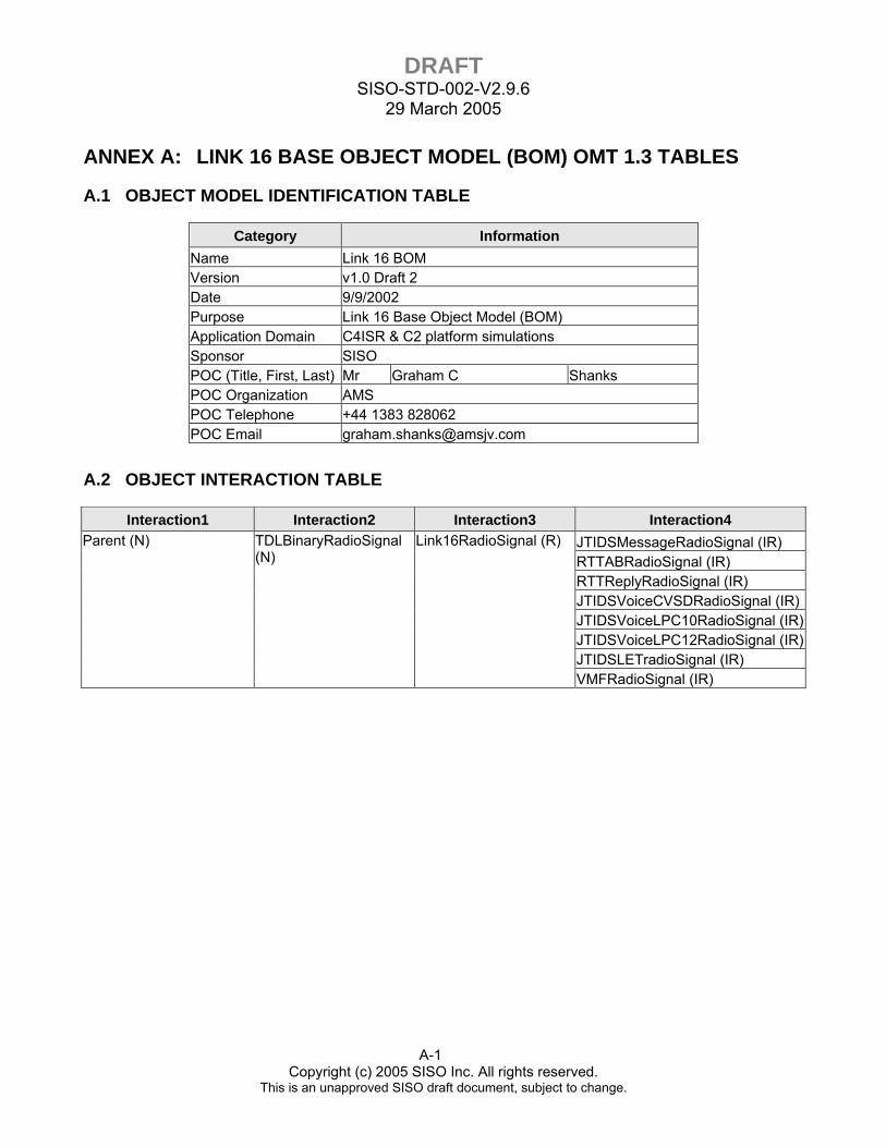
DRAFT SISO-STD-002-V2.9.6
29 March 2005
A-1 Copyright (c) 2005 SISO Inc. All rights reserved.
This is an unapproved SISO draft document, subject to change.
ANNEX A: LINK 16 BASE OBJECT MODEL (BOM) OMT 1.3 TABLES
A.1 OBJECT MODEL IDENTIFICATION TABLE
Category Information Name Link 16 BOM Version v1.0 Draft 2 Date 9/9/2002 Purpose Link 16 Base Object Model (BOM) Application Domain C4ISR & C2 platform simulations Sponsor SISO POC (Title, First, Last) Mr Graham C Shanks POC Organization AMS POC Telephone +44 1383 828062 POC Email [email protected]
A.2 OBJECT INTERACTION TABLE
Interaction1 Interaction2 Interaction3 Interaction4 JTIDSMessageRadioSignal (IR) RTTABRadioSignal (IR) RTTReplyRadioSignal (IR) JTIDSVoiceCVSDRadioSignal (IR)JTIDSVoiceLPC10RadioSignal (IR)JTIDSVoiceLPC12RadioSignal (IR)JTIDSLETradioSignal (IR)
Parent (N)
TDLBinaryRadioSignal (N)
Link16RadioSignal (R)
VMFRadioSignal (IR)
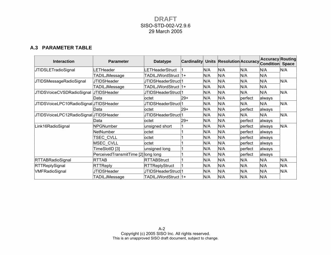
DRAFT SISO-STD-002-V2.9.6
29 March 2005
A-2 Copyright (c) 2005 SISO Inc. All rights reserved.
This is an unapproved SISO draft document, subject to change.
A.3 PARAMETER TABLE
Interaction Parameter Datatype Cardinality Units Resolution Accuracy Accuracy Condition
Routing Space
JTIDSLETradioSignal LETHeader LETHeaderStruct 1 N/A N/A N/A N/A N/A TADILJMessage TADILJWordStruct 1+ N/A N/A N/A N/A JTIDSMessageRadioSignal JTIDSHeader JTIDSHeaderStruct 1 N/A N/A N/A N/A N/A TADILJMessage TADILJWordStruct 1+ N/A N/A N/A N/A JTIDSVoiceCVSDRadioSignal JTIDSHeader JTIDSHeaderStruct 1 N/A N/A N/A N/A N/A Data octet 29+ N/A N/A perfect always JTIDSVoiceLPC10RadioSignal JTIDSHeader JTIDSHeaderStruct 1 N/A N/A N/A N/A N/A Data octet 29+ N/A N/A perfect always JTIDSVoiceLPC12RadioSignal JTIDSHeader JTIDSHeaderStruct 1 N/A N/A N/A N/A N/A Data octet 29+ N/A N/A perfect always Link16RadioSignal NPGNumber unsigned short 1 N/A N/A perfect always N/A NetNumber octet 1 N/A N/A perfect always TSEC_CVLL octet 1 N/A N/A perfect always MSEC_CVLL octet 1 N/A N/A perfect always TimeSlotID [3] unsigned long 1 N/A N/A perfect always PerceivedTransmitTime [2] long long 1 N/A N/A perfect always RTTABRadioSignal RTTAB RTTABStruct 1 N/A N/A N/A N/A N/A RTTReplySignal RTTReply RTTReplyStruct 1 N/A N/A N/A N/A N/A VMFRadioSignal JTIDSHeader JTIDSHeaderStruct 1 N/A N/A N/A N/A N/A TADILJMessage TADILJWordStruct 1+ N/A N/A N/A N/A
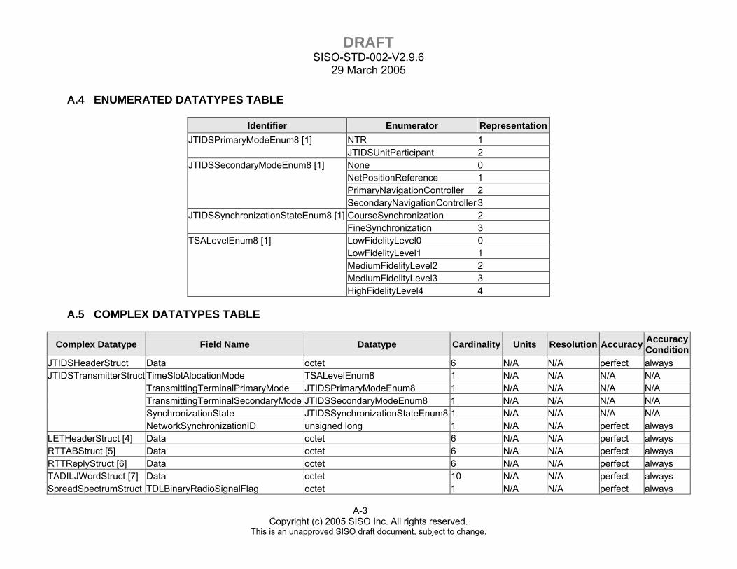
DRAFT SISO-STD-002-V2.9.6
29 March 2005
A-3 Copyright (c) 2005 SISO Inc. All rights reserved.
This is an unapproved SISO draft document, subject to change.
A.4 ENUMERATED DATATYPES TABLE
Identifier Enumerator RepresentationJTIDSPrimaryModeEnum8 [1] NTR 1 JTIDSUnitParticipant 2 JTIDSSecondaryModeEnum8 [1] None 0 NetPositionReference 1 PrimaryNavigationController 2 SecondaryNavigationController 3 JTIDSSynchronizationStateEnum8 [1] CourseSynchronization 2 FineSynchronization 3 TSALevelEnum8 [1] LowFidelityLevel0 0 LowFidelityLevel1 1 MediumFidelityLevel2 2 MediumFidelityLevel3 3 HighFidelityLevel4 4
A.5 COMPLEX DATATYPES TABLE
Complex Datatype Field Name Datatype Cardinality Units Resolution Accuracy Accuracy Condition
JTIDSHeaderStruct Data octet 6 N/A N/A perfect always JTIDSTransmitterStruct TimeSlotAlocationMode TSALevelEnum8 1 N/A N/A N/A N/A TransmittingTerminalPrimaryMode JTIDSPrimaryModeEnum8 1 N/A N/A N/A N/A TransmittingTerminalSecondaryMode JTIDSSecondaryModeEnum8 1 N/A N/A N/A N/A SynchronizationState JTIDSSynchronizationStateEnum8 1 N/A N/A N/A N/A NetworkSynchronizationID unsigned long 1 N/A N/A perfect always LETHeaderStruct [4] Data octet 6 N/A N/A perfect always RTTABStruct [5] Data octet 6 N/A N/A perfect always RTTReplyStruct [6] Data octet 6 N/A N/A perfect always TADILJWordStruct [7] Data octet 10 N/A N/A perfect always SpreadSpectrumStruct TDLBinaryRadioSignalFlag octet 1 N/A N/A perfect always

DRAFT SISO-STD-002-V2.9.6
29 March 2005
A-4 Copyright (c) 2005 SISO Inc. All rights reserved.
This is an unapproved SISO draft document, subject to change.
A.6 NOTES TABLE
ID Text 1 This is an 8-bit enumeration
2
NTP timestamp format-- NTP timestamps are represented as a 64-bit unsigned fixed-point number, in seconds relative to 0h on 1 January 1900. The integer part is in the first 32 bits and the fraction part in the last 32 bits. The precision of this representation is about 200 picoseconds, which should be adequate for even the most exotic requirements. See RFC1305 for detailed format. All F's in this field shall indicate a no statement/wildcard
3 See TimeSlot ID structure in Table 5.2.4 4 See LET Message Header structure in Table 5.2.11
5 See RTT A/B Message structure in Table 5.2.6 6 See RTT Reply Message structure in Table 5.2.7
7 See TADIL J Message Bit Orientation in Table 5.2.3
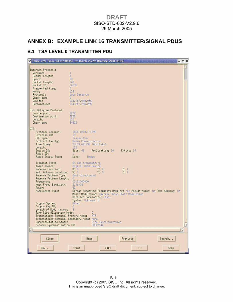
DRAFT SISO-STD-002-V2.9.6
29 March 2005
B-1 Copyright (c) 2005 SISO Inc. All rights reserved.
This is an unapproved SISO draft document, subject to change.
ANNEX B: EXAMPLE LINK 16 TRANSMITTER/SIGNAL PDUS
B.1 TSA LEVEL 0 TRANSMITTER PDU
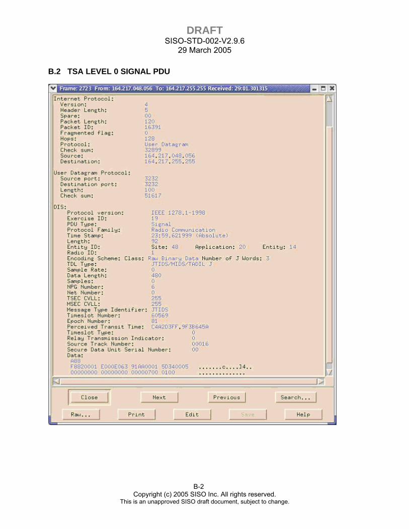
DRAFT SISO-STD-002-V2.9.6
29 March 2005
B-2 Copyright (c) 2005 SISO Inc. All rights reserved.
This is an unapproved SISO draft document, subject to change.
B.2 TSA LEVEL 0 SIGNAL PDU

DRAFT SISO-STD-002-V2.9.6
29 March 2005
B-3 Copyright (c) 2005 SISO Inc. All rights reserved.
This is an unapproved SISO draft document, subject to change.
B.3 TSA LEVEL 1 TRANSMITTER PDU
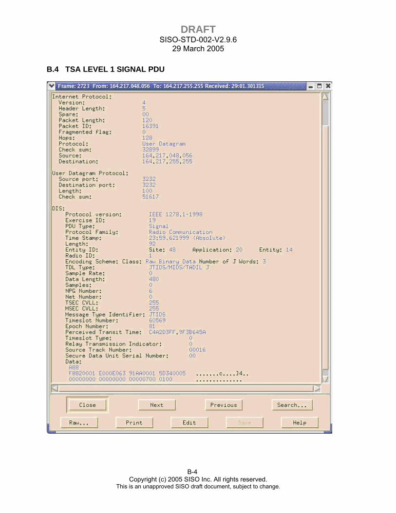
DRAFT SISO-STD-002-V2.9.6
29 March 2005
B-4 Copyright (c) 2005 SISO Inc. All rights reserved.
This is an unapproved SISO draft document, subject to change.
B.4 TSA LEVEL 1 SIGNAL PDU

DRAFT SISO-STD-002-V2.9.6
29 March 2005
B-5 Copyright (c) 2005 SISO Inc. All rights reserved.
This is an unapproved SISO draft document, subject to change.
B.5 TSA LEVEL 2 TRANSMITTER PDU
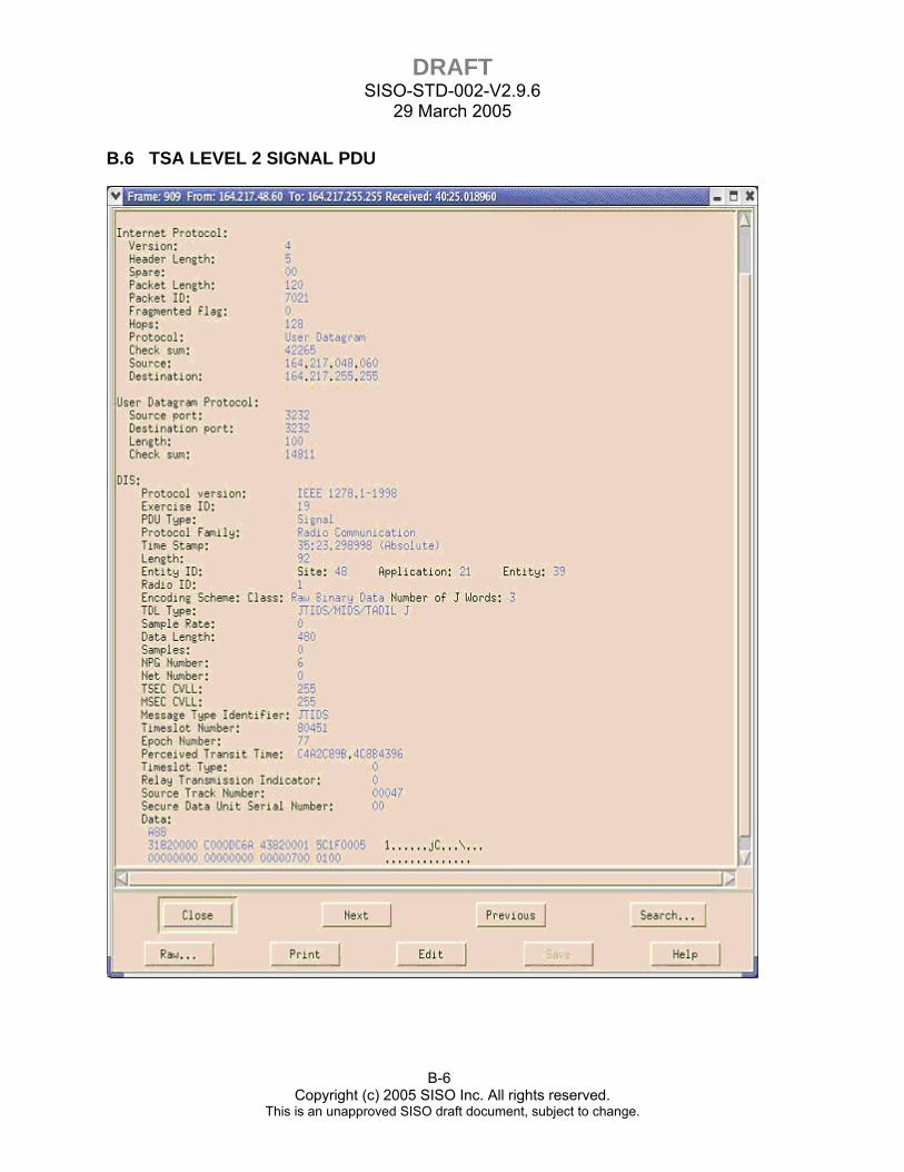
DRAFT SISO-STD-002-V2.9.6
29 March 2005
B-6 Copyright (c) 2005 SISO Inc. All rights reserved.
This is an unapproved SISO draft document, subject to change.
B.6 TSA LEVEL 2 SIGNAL PDU

DRAFT SISO-STD-002-V2.9.6
29 March 2005
B-7 Copyright (c) 2005 SISO Inc. All rights reserved.
This is an unapproved SISO draft document, subject to change.
B.7 TSA LEVEL 3 TRANSMITTER PDU
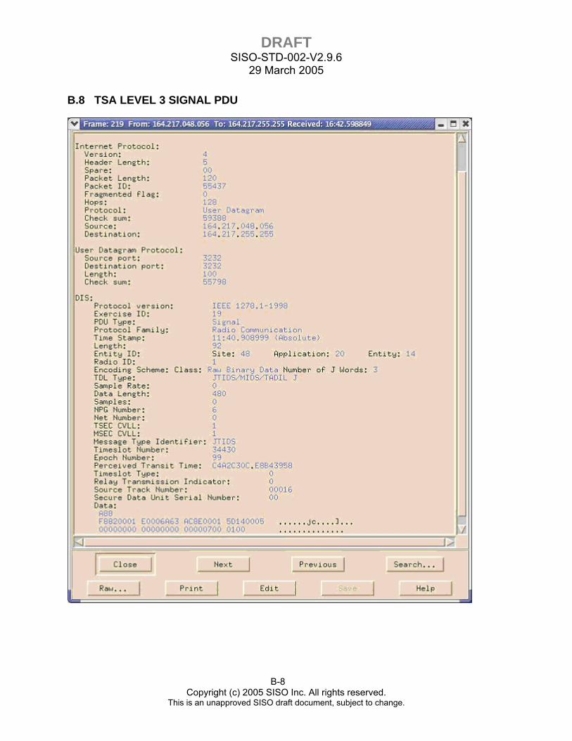
DRAFT SISO-STD-002-V2.9.6
29 March 2005
B-8 Copyright (c) 2005 SISO Inc. All rights reserved.
This is an unapproved SISO draft document, subject to change.
B.8 TSA LEVEL 3 SIGNAL PDU


![System-Level Impact of Multi-User Diversity in SISO and ...output (SISO) channels can be created, which greatly enhances link capacity of the MIMO channel [1], [2], [7]–[13]. A tradeoff](https://img.pdfslide.net/doc/110x75/6021949bc098aa318b2b0578/system-level-impact-of-multi-user-diversity-in-siso-and-output-siso-channels.jpg)


![Test case documentation and development for integration ... · Federates subscribing to a RPR 2 compliant Federation architecture. SISO-STD-001-2015 GRIM RPR FOM V2 ([1]) and SISO-REF-010-2015](https://img.pdfslide.net/doc/110x75/5f971926932735650a549ab5/test-case-documentation-and-development-for-integration-federates-subscribing.jpg)